EP3291015A1 - Photo interrupter unit, sheet conveyance apparatus and image forming apparatus - Google Patents
Photo interrupter unit, sheet conveyance apparatus and image forming apparatus Download PDFInfo
- Publication number
- EP3291015A1 EP3291015A1 EP17185226.2A EP17185226A EP3291015A1 EP 3291015 A1 EP3291015 A1 EP 3291015A1 EP 17185226 A EP17185226 A EP 17185226A EP 3291015 A1 EP3291015 A1 EP 3291015A1
- Authority
- EP
- European Patent Office
- Prior art keywords
- photo interrupter
- claw
- projection
- photo
- state
- Prior art date
- Legal status (The legal status is an assumption and is not a legal conclusion. Google has not performed a legal analysis and makes no representation as to the accuracy of the status listed.)
- Granted
Links
Images





Classifications
-
- H—ELECTRICITY
- H10—SEMICONDUCTOR DEVICES; ELECTRIC SOLID-STATE DEVICES NOT OTHERWISE PROVIDED FOR
- H10F—INORGANIC SEMICONDUCTOR DEVICES SENSITIVE TO INFRARED RADIATION, LIGHT, ELECTROMAGNETIC RADIATION OF SHORTER WAVELENGTH OR CORPUSCULAR RADIATION
- H10F55/00—Radiation-sensitive semiconductor devices covered by groups H10F10/00, H10F19/00 or H10F30/00 being structurally associated with electric light sources and electrically or optically coupled thereto
-
- G—PHYSICS
- G03—PHOTOGRAPHY; CINEMATOGRAPHY; ANALOGOUS TECHNIQUES USING WAVES OTHER THAN OPTICAL WAVES; ELECTROGRAPHY; HOLOGRAPHY
- G03G—ELECTROGRAPHY; ELECTROPHOTOGRAPHY; MAGNETOGRAPHY
- G03G15/00—Apparatus for electrographic processes using a charge pattern
- G03G15/50—Machine control of apparatus for electrographic processes using a charge pattern, e.g. regulating differents parts of the machine, multimode copiers, microprocessor control
-
- B—PERFORMING OPERATIONS; TRANSPORTING
- B65—CONVEYING; PACKING; STORING; HANDLING THIN OR FILAMENTARY MATERIAL
- B65H—HANDLING THIN OR FILAMENTARY MATERIAL, e.g. SHEETS, WEBS, CABLES
- B65H3/00—Separating articles from piles
- B65H3/02—Separating articles from piles using friction forces between articles and separator
- B65H3/06—Rollers or like rotary separators
-
- B—PERFORMING OPERATIONS; TRANSPORTING
- B65—CONVEYING; PACKING; STORING; HANDLING THIN OR FILAMENTARY MATERIAL
- B65H—HANDLING THIN OR FILAMENTARY MATERIAL, e.g. SHEETS, WEBS, CABLES
- B65H5/00—Feeding articles separated from piles; Feeding articles to machines
- B65H5/06—Feeding articles separated from piles; Feeding articles to machines by rollers or balls, e.g. between rollers
- B65H5/062—Feeding articles separated from piles; Feeding articles to machines by rollers or balls, e.g. between rollers between rollers or balls
-
- B—PERFORMING OPERATIONS; TRANSPORTING
- B65—CONVEYING; PACKING; STORING; HANDLING THIN OR FILAMENTARY MATERIAL
- B65H—HANDLING THIN OR FILAMENTARY MATERIAL, e.g. SHEETS, WEBS, CABLES
- B65H7/00—Controlling article feeding, separating, pile-advancing, or associated apparatus, to take account of incorrect feeding, absence of articles, or presence of faulty articles
- B65H7/02—Controlling article feeding, separating, pile-advancing, or associated apparatus, to take account of incorrect feeding, absence of articles, or presence of faulty articles by feelers or detectors
- B65H7/14—Controlling article feeding, separating, pile-advancing, or associated apparatus, to take account of incorrect feeding, absence of articles, or presence of faulty articles by feelers or detectors by photoelectric feelers or detectors
-
- G—PHYSICS
- G03—PHOTOGRAPHY; CINEMATOGRAPHY; ANALOGOUS TECHNIQUES USING WAVES OTHER THAN OPTICAL WAVES; ELECTROGRAPHY; HOLOGRAPHY
- G03G—ELECTROGRAPHY; ELECTROPHOTOGRAPHY; MAGNETOGRAPHY
- G03G15/00—Apparatus for electrographic processes using a charge pattern
- G03G15/50—Machine control of apparatus for electrographic processes using a charge pattern, e.g. regulating differents parts of the machine, multimode copiers, microprocessor control
- G03G15/5029—Machine control of apparatus for electrographic processes using a charge pattern, e.g. regulating differents parts of the machine, multimode copiers, microprocessor control by measuring the copy material characteristics, e.g. weight, thickness
-
- G—PHYSICS
- G03—PHOTOGRAPHY; CINEMATOGRAPHY; ANALOGOUS TECHNIQUES USING WAVES OTHER THAN OPTICAL WAVES; ELECTROGRAPHY; HOLOGRAPHY
- G03G—ELECTROGRAPHY; ELECTROPHOTOGRAPHY; MAGNETOGRAPHY
- G03G21/00—Arrangements not provided for by groups G03G13/00 - G03G19/00, e.g. cleaning, elimination of residual charge
- G03G21/16—Mechanical means for facilitating the maintenance of the apparatus, e.g. modular arrangements
-
- G—PHYSICS
- G03—PHOTOGRAPHY; CINEMATOGRAPHY; ANALOGOUS TECHNIQUES USING WAVES OTHER THAN OPTICAL WAVES; ELECTROGRAPHY; HOLOGRAPHY
- G03G—ELECTROGRAPHY; ELECTROPHOTOGRAPHY; MAGNETOGRAPHY
- G03G21/00—Arrangements not provided for by groups G03G13/00 - G03G19/00, e.g. cleaning, elimination of residual charge
- G03G21/16—Mechanical means for facilitating the maintenance of the apparatus, e.g. modular arrangements
- G03G21/1642—Mechanical means for facilitating the maintenance of the apparatus, e.g. modular arrangements for connecting the different parts of the apparatus
- G03G21/1647—Mechanical connection means
-
- H—ELECTRICITY
- H05—ELECTRIC TECHNIQUES NOT OTHERWISE PROVIDED FOR
- H05K—PRINTED CIRCUITS; CASINGS OR CONSTRUCTIONAL DETAILS OF ELECTRIC APPARATUS; MANUFACTURE OF ASSEMBLAGES OF ELECTRICAL COMPONENTS
- H05K7/00—Constructional details common to different types of electric apparatus
- H05K7/02—Arrangements of circuit components or wiring on supporting structure
- H05K7/12—Resilient or clamping means for holding component to structure
-
- B—PERFORMING OPERATIONS; TRANSPORTING
- B65—CONVEYING; PACKING; STORING; HANDLING THIN OR FILAMENTARY MATERIAL
- B65H—HANDLING THIN OR FILAMENTARY MATERIAL, e.g. SHEETS, WEBS, CABLES
- B65H2402/00—Constructional details of the handling apparatus
- B65H2402/30—Supports; Subassemblies; Mountings thereof
-
- B—PERFORMING OPERATIONS; TRANSPORTING
- B65—CONVEYING; PACKING; STORING; HANDLING THIN OR FILAMENTARY MATERIAL
- B65H—HANDLING THIN OR FILAMENTARY MATERIAL, e.g. SHEETS, WEBS, CABLES
- B65H2402/00—Constructional details of the handling apparatus
- B65H2402/60—Coupling, adapter or locking means
-
- B—PERFORMING OPERATIONS; TRANSPORTING
- B65—CONVEYING; PACKING; STORING; HANDLING THIN OR FILAMENTARY MATERIAL
- B65H—HANDLING THIN OR FILAMENTARY MATERIAL, e.g. SHEETS, WEBS, CABLES
- B65H2553/00—Sensing or detecting means
- B65H2553/40—Sensing or detecting means using optical, e.g. photographic, elements
- B65H2553/41—Photoelectric detectors
- B65H2553/412—Photoelectric detectors in barrier arrangements, i.e. emitter facing a receptor element
-
- B—PERFORMING OPERATIONS; TRANSPORTING
- B65—CONVEYING; PACKING; STORING; HANDLING THIN OR FILAMENTARY MATERIAL
- B65H—HANDLING THIN OR FILAMENTARY MATERIAL, e.g. SHEETS, WEBS, CABLES
- B65H2553/00—Sensing or detecting means
- B65H2553/60—Details of intermediate means between the sensing means and the element to be sensed
- B65H2553/61—Mechanical means, e.g. contact arms
-
- B—PERFORMING OPERATIONS; TRANSPORTING
- B65—CONVEYING; PACKING; STORING; HANDLING THIN OR FILAMENTARY MATERIAL
- B65H—HANDLING THIN OR FILAMENTARY MATERIAL, e.g. SHEETS, WEBS, CABLES
- B65H2701/00—Handled material; Storage means
- B65H2701/10—Handled articles or webs
- B65H2701/11—Dimensional aspect of article or web
- B65H2701/113—Size
- B65H2701/1131—Size of sheets
-
- B—PERFORMING OPERATIONS; TRANSPORTING
- B65—CONVEYING; PACKING; STORING; HANDLING THIN OR FILAMENTARY MATERIAL
- B65H—HANDLING THIN OR FILAMENTARY MATERIAL, e.g. SHEETS, WEBS, CABLES
- B65H2801/00—Application field
- B65H2801/03—Image reproduction devices
-
- B—PERFORMING OPERATIONS; TRANSPORTING
- B65—CONVEYING; PACKING; STORING; HANDLING THIN OR FILAMENTARY MATERIAL
- B65H—HANDLING THIN OR FILAMENTARY MATERIAL, e.g. SHEETS, WEBS, CABLES
- B65H2801/00—Application field
- B65H2801/03—Image reproduction devices
- B65H2801/06—Office-type machines, e.g. photocopiers
-
- G—PHYSICS
- G03—PHOTOGRAPHY; CINEMATOGRAPHY; ANALOGOUS TECHNIQUES USING WAVES OTHER THAN OPTICAL WAVES; ELECTROGRAPHY; HOLOGRAPHY
- G03G—ELECTROGRAPHY; ELECTROPHOTOGRAPHY; MAGNETOGRAPHY
- G03G21/00—Arrangements not provided for by groups G03G13/00 - G03G19/00, e.g. cleaning, elimination of residual charge
- G03G21/16—Mechanical means for facilitating the maintenance of the apparatus, e.g. modular arrangements
- G03G21/1661—Mechanical means for facilitating the maintenance of the apparatus, e.g. modular arrangements means for handling parts of the apparatus in the apparatus
- G03G21/1695—Mechanical means for facilitating the maintenance of the apparatus, e.g. modular arrangements means for handling parts of the apparatus in the apparatus for paper transport
-
- G—PHYSICS
- G03—PHOTOGRAPHY; CINEMATOGRAPHY; ANALOGOUS TECHNIQUES USING WAVES OTHER THAN OPTICAL WAVES; ELECTROGRAPHY; HOLOGRAPHY
- G03G—ELECTROGRAPHY; ELECTROPHOTOGRAPHY; MAGNETOGRAPHY
- G03G2215/00—Apparatus for electrophotographic processes
- G03G2215/00362—Apparatus for electrophotographic processes relating to the copy medium handling
- G03G2215/00535—Stable handling of copy medium
- G03G2215/00717—Detection of physical properties
- G03G2215/00721—Detection of physical properties of sheet position
-
- G—PHYSICS
- G03—PHOTOGRAPHY; CINEMATOGRAPHY; ANALOGOUS TECHNIQUES USING WAVES OTHER THAN OPTICAL WAVES; ELECTROGRAPHY; HOLOGRAPHY
- G03G—ELECTROGRAPHY; ELECTROPHOTOGRAPHY; MAGNETOGRAPHY
- G03G2221/00—Processes not provided for by group G03G2215/00, e.g. cleaning or residual charge elimination
- G03G2221/16—Mechanical means for facilitating the maintenance of the apparatus, e.g. modular arrangements and complete machine concepts
- G03G2221/1606—Mechanical means for facilitating the maintenance of the apparatus, e.g. modular arrangements and complete machine concepts for the photosensitive element
Definitions
- the present invention relates to a photo interrupter unit including a photo interrupter, and a sheet conveyance apparatus and an image forming apparatus comprising the same.
- a photo interrupter provided on a slot machine, a camera, a printer and the like is known to detect presence of a detection target object by switching between a state in which light irradiated from a light emitting portion reaches a photo sensing portion and in which light does not reach the photo sensing portion.
- a photo interrupter disposed on a printer is a photo interrupter in which light irradiated from the light emitting portion to the photo sensing portion is blocked by a flag that moves when being pressed by a sheet being conveyed, based on which the presence of a sheet is detected.
- the photo interrupter is fixed by a so-called snap fit structure in which an elastically deformable claw portion is fit into a locking hole.
- a locking failure may occur in which the snap fit is disengaged or is half-locked. If the locking failure is discovered after the assembling of related components has been completed, the unit including the photo interrupter must be discarded as a defective product, or the unit must be disassembled and then reassembled, according to which a large amount of loss or deterioration of productivity has been caused.
- a photo interrupter unit has been proposed in which a fall-preventing cover 90 is provided in addition to a photo interrupter 70 and a sensor support member 80, as illustrated in FIG. 14A .
- the operator mounts the photo interrupter 70 to the sensor support member 80, and thereafter, as illustrated in FIG. 14B , locks a connecting piece 96 of the fall-preventing cover 90 to a locking claw 82 of the sensor support member 80, by which the fall-preventing cover 90 is mounted to the sensor support member 80.
- the fall-preventing cover 90 prevents the photo interrupter 70 from dropping from the sensor support member 80 even if external force is applied to the photo interrupter unit.
- the photo interrupter unit disclosed in the above-mentioned Japanese Unexamined Patent Application Publication No. 2009-66077 has a drawback in that both size and cost of the apparatus are increased by providing the fall-preventing cover. Further, the additional step of assembling the fall-preventing cover deteriorates productivity.
- the present invention in its first aspect provides a photo interrupter unit as specified in claims 1 to 12.
- the present invention in its second aspect provides a sheet conveyance apparatus as specified in claim 13.
- the present invention in its third aspect provides an image forming apparatus as specified in claim 14.
- FIG. 1 is an entire schematic diagram illustrating a printer according to a first embodiment.
- FIG. 2A is a perspective view illustrating a conveyance guide and a sensor flag.
- FIG. 2B is a perspective view illustrating the sensor flag from a rear side.
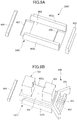
- FIG. 3A is a perspective view illustrating a state in which a photo interrupter is attached to a mounting portion.
- FIG. 3B is a perspective view illustrating a mounting portion in a state where the photo interrupter is removed.
- FIG. 3C is a perspective view illustrating the mounting portion from a rear surface.
- FIG. 4A is a cross-sectional view illustrating a photo interrupter unit.
- FIG. 4B is a side view illustrating a photo interrupter unit.
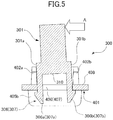
- FIG. 5 is a cross-sectional view illustrating a photo interrupter in a state where external force is applied.
- FIG. 6A is a cross-sectional view illustrating a method of mounting the photo interrupter vertically.
- FIG. 6B is a cross-sectional view illustrating a method of mounting the photo interrupter in an inclined manner.
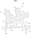
- FIG. 7 is a cross-sectional view illustrating a photo interrupter unit as a comparative example.
- FIG. 8A is a perspective view illustrating a state in which the photo interrupter is mounted to the mounting portion in a reversed state.
- FIG. 8B is a cross-sectional view illustrating a state in which the photo interrupter is mounted to the mounting portion in a reversed state.
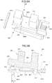
- FIG. 9A is a perspective view illustrating a comparative example of a mounting portion in a state where the photo interrupter is removed.
- FIG. 9B is a perspective view illustrating a comparative example of a mounting portion in a state where the photo interrupter is attached.
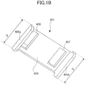
- FIG. 10 is a perspective view illustrating a dimension of a rear surface rib.
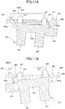
- FIG. 11A is a cross-sectional view illustrating a state in which the photo interrupter is mounted from a rear surface side.
- FIG. 11B is a cross-sectional view illustrating a state in which the photo interrupter in a reversed state is mounted from the rear surface side.
- FIG. 12A is a cross-sectional view illustrating a photo interrupter and a mounting portion according to a second embodiment.
- FIG. 12B is a cross-sectional view illustrating a method for mounting the photo interrupter.
- FIG. 13A is a cross-sectional view illustrating a photo interrupter and a mounting portion.
- FIG. 13B is a cross-sectional view illustrating a photo interrupter in a state where external force is applied thereto.
- FIG. 14A is an exploded perspective view illustrating a conventional photo interrupter and fall-preventing cover.
- FIG. 14B is a perspective view illustrating the conventional photo interrupter and fall-preventing cover.
- FIG. 1 is an entire schematic diagram illustrating a configuration of a printer adopting an electro-photographic system according to the first embodiment.
- a printer 900 serving as an image forming apparatus comprises, as illustrated in FIG. 1 , a printer body (hereinafter referred to as apparatus body) 900A having an image forming portion 900B, serving as an image forming means, configured to form an image on a sheet, and an image reading apparatus 950 having a document conveyance apparatus 950A.
- the image forming portion 900B includes photosensitive drums 18a through 18d configured to form toner images of four colors, which are yellow, magenta, cyan and black, and an exposing unit 906 configured to irradiate laser beams based on image information to form an electrostatic latent image on the photosensitive drum.
- the photosensitive drums 18a through 18d are driven by a motor not shown, and in the circumference of the drums are respectively arranged a primary charging device, a developing unit and a transfer charging device not shown, the devices formed into units as process cartridges 901a through 901d.
- the image forming portion 900B includes an intermediate transfer belt 902 driven to rotate in the direction of the arrow in the drawing, and a secondary transfer portion 903 configured to transfer a full color image sequentially formed on the intermediate transfer belt 902 to a sheet P. Then, a transfer bias is applied from the transfer charging devices 902a through 902d to the intermediate transfer belt 902, and the toner images of respective colors on the photosensitive drum are sequentially transferred in multilayers to the intermediate transfer belt 902. Thereby, a full color image is formed on the intermediate transfer belt 902.
- the secondary transfer portion 903 is composed of a secondary transfer counter roller 903b configured to support the intermediate transfer belt 902, and a secondary transfer roller 903a abutted against the secondary transfer counter roller 903b via the intermediate transfer belt 902. Further, a sheet feed cassette 904 is arranged below the image forming portion 900B, and sheets P supported on the sheet feed cassette 904 are fed by a pickup roller 908 serving as a conveyance means. A registration roller 909 is disposed downstream of the pickup roller 908 in a conveyance direction. A control unit 200 is provided on the apparatus body 900A.
- the exposing unit 906 irradiates laser beams based on image information transmitted from a personal computer or the like not shown, and the photosensitive drums 18a through 18d whose surfaces are charged uniformly are exposed sequentially, by which electrostatic latent images are formed on the photosensitive drums 18a through 18d. Thereafter, the electrostatic latent images are developed by toner and visualized.
- a laser beam based on an image signal corresponding to a yellow component color of the document is irradiated via a polygon mirror of the exposing unit 906, and a yellow electrostatic latent image is formed on the photosensitive drum 18a.
- the yellow electrostatic latent image is developed using yellow toner from the developing unit, and visualized as a yellow toner image.
- the toner image reaches a primary transfer portion where the photosensitive drum 18a and the intermediate transfer belt 902 abut against one another.
- the yellow toner image on the photosensitive drum 18a is transferred to the intermediate transfer belt 902 by a primary transfer bias applied to a transfer charging device 902a.
- magenta, cyan and black toner images formed on the photosensitive drums 18b through 18d are transferred onto the yellow toner image borne on the intermediate transfer belt 902 by a similar method as described above. Thereby, a full-color toner image is formed on the intermediate transfer belt 902.
- the sheet P stored in the sheet feed cassette 904 is sent out one by one at a time by the pickup roller 908.
- the sheet P is passed between conveyance guides 910 and 911 and reaches the registration roller 909, where a skew of the sheet P is corrected by the registration roller 909, and the sheet P is conveyed to the secondary transfer portion 903.
- the secondary transfer portion 903 the four-color toner images on the intermediate transfer belt 902 are collectively transferred onto the sheet P by a secondary transfer bias applied to the secondary transfer roller 903a.
- the sheet P to which the toner image has been transferred is guided from the secondary transfer portion 903 to a conveyance guide 920 and conveyed to a fixing portion 905, and while the sheet passes the fixing portion 905, heat and pressure is applied and the toner image is fixed. Thereafter, the sheet P to which the toner image has been fixed passes a sheet discharge conveyance guide 921 arranged downstream in the conveyance direction of the fixing portion 905, and the sheet P is discharged via a sheet discharge roller pair 918 to a sheet discharge tray 922.
- FIG. 2A is a perspective view illustrating a conveyance guide 910, the registration roller 909 and a pressing portion 912. For sake of description, the opposing registration roller and other components are not shown.
- FIG. 2B is a view illustrating a flag unit 916 from a rear side.
- a mounting portion 401 serving as a supporting means is formed integrally to the conveyance guide 910, and a photo interrupter 301 is removably mounted to the mounting portion 401.
- the photo interrupter 301 includes a light emitting portion 302, serving as a light emitting means, having a light emitting element arranged on an interior thereof, and a photo sensing portion 303, serving as a photo sensing means, retaining a light receiving element in an interior thereof.
- the flag unit 916 serving as a moving means is mounted to the conveyance guide 910.
- the flag unit 916 includes a pivot shaft 913 pivotably supported on the conveyance guide 910, and a pressing portion 912 and a flag portion 914 respectively uniformly fixed to the pivot shaft 913.
- the pressing portion 912 is projected through a long hole 910a formed on the conveyance guide 910 to a conveyance path CP defined by the conveyance guides 910 and 911 (refer to FIG. 1 ).
- the flag portion 914 is configured to enter between the light emitting portion 302 and the photo sensing portion 303, and blocks light emitted from the light emitting portion 302.
- the flag unit 916 is urged by a torsion spring 915 mounted on the pivot shaft 913 such that the pressing portion 912 is projected to the conveyance path CP and such that the flag portion 914 is arranged at a rotation angle that does not block light emitted from the light emitting portion 302.
- the photo interrupter 301 in a state where there is no sheet on the conveyance path CP, the photo interrupter 301 is in at a light reception state in which the light emitted from the light emitting portion 302 is received by the photo sensing portion 303.
- the flag portion 914 pivots together with the pivot shaft 913 against the urging force of the torsion spring 915. Then, the light emitted from the light emitting portion 302 to the photo sensing portion 303 is blocked by the flag portion 914. That is, if a sheet exists in the conveyance path CP, the photo interrupter 301 will be in a light blocked state in which the light emitted from the light emitting portion 302 to the photo sensing portion 303 is blocked.
- the photo interrupter 301 outputs detection signals that differ between the light reception state and the light blocked state to the control unit 200. Then, in a state where the photo interrupter 301 is changed from the light reception state to the light blocked state, the control unit 200 detects that a tip of the sheet P has reached a position of the pressing portion 912. In a state where a trailing edge of the sheet P being conveyed passes the pressing portion 912, the flag portion 914 pivots together with the pivot shaft 913 by the urging force of the torsion spring 915, and the photo interrupter 301 shifts from the light blocked state to the light reception state. Thereby, it is detected that the trailing edge of the sheet P has passed the position of the pressing portion 912.
- the pickup roller 908, the flag unit 916 and a photo interrupter unit 300 described later constitute a sheet conveyance apparatus through which the sheet is conveyed.
- FIG. 3A is a perspective view illustrating the photo interrupter unit 300 in which the photo interrupter 301 is mounted to the mounting portion 401.
- FIG. 3B is a perspective view in which the mounting portion 401 to which the photo interrupter 301 is mounted is viewed from a mounting surface 408 side.
- FIG. 3C is a perspective view in which the mounting portion 401 is viewed from a rear surface 409 side. In FIGs. 3A through 3C , a portion of the mounting portion 401 is removed.
- a connector portion 304 serving as a connector means, electrically connected to the control unit 200 via a wiring is provided on the photo interrupter 301, and the connector portion 304, the light emitting portion 302 and the photo sensing portion 303 are arranged in alignment in a longitudinal direction, that is, in an orthogonal direction.
- a plurality of connector pins 305 are arranged on an inner side of the connector portion 304.
- An exterior of the photo interrupter 301 including the connector portion 304, the light emitting portion 302, the photo sensing portion 303, and first and second claw portions 306 and 307 described later is formed of a resin having elasticity, such as a polycarbonate.
- the mounting portion 401 includes the mounting surface 408 to which the photo interrupter 301 is mounted, and a first engagement hole portion 406 serving as an insertion hole means and a second engagement hole portion 407 serving as a hole means arranged in a longitudinal direction are formed to the mounting surface 408.
- the first engagement hole portion 406 forms an insertion hole through which the first claw portion 306 is inserted
- the second engagement hole portion 407 forms a hole through which the second claw portion 307 is inserted.
- a pair of support ribs 402a and 402b, a reverse prevention rib 403 and a connector support rib 404 are projected vertically with respect to the mounting surface 408 from the mounting surface 408.
- the pair of support ribs 402a and 402b serving as a projection and a first projection are extended along a longitudinal direction, and arranged with a clearance in a short-length direction, that is, deforming direction, orthogonal to the longitudinal direction.
- the pair of support ribs 402a and 402b is respectively opposed to side surfaces 301a and 301b of the photo interrupter 301 with a slight gap formed therebetween.
- the reverse prevention rib 403 serving as a second projection portion is formed to extend in the short-length direction so as to connect a first end portion of each of the pair of support ribs 402a and 402b.
- the connector support rib 404 is arranged on an opposite side from the reverse prevention rib 403 in the longitudinal direction interposing the first engagement hole portion 406 and the second engagement hole portion 407.
- the connector support rib 404 is set to a height such that a slight gap is formed with respect to the connector portion 304 in a state where the photo interrupter 301 is attached to the mounting portion 401, and supports the connector portion 304 in a state where the connector portion 304 is pressed from above and bent.
- a pair of rear surface ribs 405a and 405b serving as opposite surface side ribs are projected vertically from the rear surface 409 serving as an opposite surface from the mounting surface 408 of the mounting portion 401.
- the first engagement hole portion 406 and the second engagement hole portion 407 are formed to pass through the mounting surface 408 to the rear surface 409 between the pair of rear surface ribs 405a and 405b.
- FIG. 4A is a cross-sectional view illustrating a state in which the photo interrupter 301 is attached to the mounting portion 401.
- FIG. 4B is a side view illustrating a state in which the photo interrupter 301 is attached to the mounting portion 401.
- the photo interrupter 301 includes the first claw portion 306 serving as a leg means and the second claw portion 307 serving as a claw means that can be respectively engaged with the first engagement hole portion 406 and the second engagement hole portion 407.
- the first claw portion 306 and the second claw portion 307 have claw shaped portions formed at a tip portion thereof, and the photo interrupter 301 is attached to the mounting portion 401 by the first claw portion 306 and the second claw portion 307 being engaged with the first engagement hole portion 406 and the second engagement hole portion 407.
- the first claw portion 306 and the second claw portion 307 are connected to the first engagement hole portion 406 and the second engagement hole portion 407 via a so-called snap fit structure.
- the first claw portion 306 and the second claw portion 307 have identical shapes.
- the first claw portion 306 has a pair of claws 306a and 306b, and the pair of claws 306a and 306b are formed of resin such that the claws are elastically deformable in the short-length direction, that is, in left and right direction of FIG. 4A .
- the second claw portion 307 has a pair of claws 307a and 307b, and the pair of claws 307a and 307b are formed of resin such that the claws are elastically deformable in the short-length direction.
- the pair of claws 306a and 306b and the pair of claws 307a and 307b have tapered portions provided at an outer side in the short-length direction.
- the pair of claws 306a and 306b and the pair of claws 307a and 307b are inserted to a depth such that the claw shapes of the tips of the pair of claws 306a and 306b and the pair of claws 307a and 307b enter the first engagement hole portion 406 and the second engagement hole portion 407. Then, the pair of claws 306a and 306b and the pair of claws 307a and 307b are restored to their original shapes, and as illustrated in FIGs. 4A and 4B , the photo interrupter 301 will be in a mounted state to the mounting portion 401.
- FIG. 5 is a cross-sectional view illustrating the photo interrupter 301 in a state where external force A is applied to a direction parallel to the mounting surface 408, that is, in the short-length direction.
- the photo interrupter 301 attempts to rotate in a direction parallel to the short-length direction.
- a slight gap of approximately 0.2 mm is respectively formed between the side surfaces 301a and 301b of the photo interrupter 301 and the pair of support ribs 402a and 402b, by which the mounting property of the photo interrupter 301 is improved.
- the short-length direction is a direction that intersects the direction of insertion of the first and second claw portions 306 and 307 of the photo interrupter 301.
- a height B from the mounting surface 408 to a tip of the pair of support ribs 402a and 402b is set higher than a height C from the mounting surface 408 to a base portion 310, serving as a base means, of the first and second claw portions 306 and 307. Therefore, the pair of support ribs 402a and 402b can support the photo interrupter 301 near a top board 309 of the photo interrupter 301 where bend is relatively unlikely to occur, enabling the photo interrupter to endure greater external force.
- the pair of support ribs 402a and 402b is formed integrally to the mounting portion 401, there is no need to provide a separate member for preventing fall of the photo interrupter 301, and the increase in size and cost of the photo interrupter unit 300 can be prevented.
- FIG. 6A is a view illustrating a method for mounting the photo interrupter 301 vertically to the mounting portion 401
- FIG. 6B is a view illustrating a method for mounting the photo interrupter 301 obliquely to the mounting portion 401.
- the photo interrupter 301 is mounted to the mounting surface 408 of the mounting portion 401 from a vertical direction D vertical with respect to the mounting surface 408. That is, the first claw portion 306 and the second claw portion 307 of the photo interrupter 301 are simultaneously inserted to the first engagement hole portion 406 and the second engagement hole portion 407 of the mounting portion 401, and engagement is completed simultaneously.
- the photo interrupter 301 can be mounted to the mounting portion 401 by rotating the photo interrupter 301 in an arrow E direction in a state where the first claw portion 306 is engaged with the first engagement hole portion 406.
- the reverse prevention rib 403 is disposed at a position where the first claw portion 306 is not abutted against the photo interrupter 301 in a state engaged with the first engagement hole portion 406. That is, the reverse prevention rib 403 is arranged such that it does not interfere with the photo interrupter 301 even if the second claw portion 307 enters the second engagement hole portion 407 in a state where the first claw portion 306 is inserted to the first engagement hole portion 406.
- FIG. 7 is a cross-sectional view illustrating a the photo interrupter unit 1300 as a comparative example in which the reverse prevention rib 403 of the mounting portion 401 illustrated in FIG. 6B is arranged close to the first engagement hole portion 406.
- a mounting portion 1401 includes a reverse prevention rib 1403 arranged at a position close to the first engagement hole portion 406.
- the photo interrupter 301 and the reverse prevention rib 1403 abut against one another before the engagement of the first claw portion 306 and the first engagement hole portion 406 is completed. That is, as illustrated in FIG. 7 , a state may occur in which the photo interrupter 301 abuts against the reverse prevention rib 1403 and the first claw portion 306 contacts an edge of the first engagement hole portion 406, that is, the edge of the first engagement hole portion 406 on a side facing the reverse prevention rib 1403.
- first claw portion 306 If the first claw portion 306 is pushed with force from above and engaged to the first engagement hole portion 406 in this state, plastic deformation of the first claw portion 306 will occur, and mounting failure is caused. If the first claw portion 306 experiences plastic deformation once, the photo interrupter 301 can no longer be mounted, such that the photo interrupter 301 having experienced plastic deformation must be discarded.
- the photo interrupter unit 300 illustrated in FIG. 6B has the reverse prevention rib 403 arranged at a predetermined distance from the first engagement hole portion 406. Therefore, the abutment of the photo interrupter 301 and the reverse prevention rib 403 will not occur simultaneously as the abutment of the first claw portion 306 and the edge of the first engagement hole portion 406. Therefore, even if the first claw portion 306 is engaged with the first engagement hole portion 406 first, plastic deformation of the first claw portion 306 as described with reference to FIG. 7 will not occur. Therefore, according to the first embodiment illustrated in FIG.
- the photo interrupter 301 will not be discarded due to an erroneous mounting method, such that the mounting workability will be improved and costs can be reduced. Since there is no need to carry out a step of assembling an independent component other than the photo interrupter 301 to the mounting portion 401, the productivity can be improved.
- FIG. 8A is a perspective view illustrating a state in which the photo interrupter 301 is mounted to the mounting portion 401 in a state where the photo interrupter 301 is rotated for 180 degrees
- FIG. 8B is a cross-sectional view thereof.
- the pair of support ribs 402a and 402b and the reverse prevention rib 403 is formed in a continuous manner and higher than a height D from the mounting surface 408 to the connector portion 304, as illustrated in FIGs. 8A and 8B .
- a length L from the first engagement hole portion 406 to the reverse prevention rib 403 is set shorter than a length K (refer to FIG.
- FIG. 9A illustrates a perspective view illustrating a mounting portion 2401 as a comparative example in which the pair of the support ribs 402a and 402b and the reverse prevention rib 403 are formed in a separated manner
- FIG. 9B is a perspective view illustrating a state in which the photo interrupter 301 is mounted. If the photo interrupter 301 is attached to the mounting portion 2401 in a state where the photo interrupter 301 is reversed, the connector portion 304 abuts against the reverse prevention rib 403 as described earlier.
- the connector portion 304 may be deformed and the photo interrupter 301 may be mounted to the mounting portion 2401, as illustrated in FIG. 9B .
- the reverse prevention rib 403 abuts against the connector pins 305, and the connector pins 305 may be damaged.
- the pair of support ribs 402a and 402b and the reverse prevention rib 403 are formed continuously, such that even if the connector portion 304 is bent, the photo interrupter 301 will not be mounted to the mounting portion 401 in the reversed state.
- FIG. 10 is a perspective view illustrating the dimension of the rear surface ribs 405a and 405b.
- FIG. 11A is a cross-sectional view illustrating a state in which the photo interrupter 301 is mounted from the rear surface 409 side of the mounting portion 401.
- FIG. 11B is a cross-sectional view illustrating a state in which the photo interrupter 301 is mounted in a reversed state from the state illustrated in FIG. 11A .
- a length G of the pair of rear surface ribs 405a and 405b in the short-length direction is set greater than a length N (refer to FIG. 4A ) of the reverse prevention rib 403. Further, as illustrated in FIG. 4B , a height P of the rear surface ribs 405a and 405b is set even greater than the greater one of the height D from the mounting surface 408 to the connector portion 304 or a length M from the mounting surface 408 to the tip of the first and second claw portions 306 and 307.
- the connector portion 304 will abut against a rear surface rib 405b, and the photo interrupter 301 is prevented from being mounted to the rear surface 409.
- the rear surface ribs 405a and 405b interfere with the photo interrupter 301 before the photo interrupter 301 is mounted to the mounting portion 401 from the rear surface 409 side.
- the second embodiment adopts a configuration in which the first claw portion 306 of the photo interrupter 301 according to the first embodiment is replaced with a hook portion 321. Therefore, configurations similar to the first embodiment are either omitted from the drawing or denoted with the same reference numbers for description.
- FIGs. 12A and 13A are cross-sectional views illustrating a state in which the photo interrupter 320 according to the second embodiment is attached to a mounting portion 421.
- FIG. 12B is a cross-sectional view illustrating a method for mounting the photo interrupter 320.
- FIG. 13B is a cross-sectional view illustrating a state in which an external force A is applied on the photo interrupter 320.
- the photo interrupter 320 includes the light emitting portion 302, the photo sensing portion 303, the connector portion 304, the hook portion 321 and the second claw portion 307.
- the hook portion 321 serving as a leg portion is shaped like a hook in which the tip is bent in the longitudinal direction.
- the mounting portion 421 includes the mounting surface 408, the first engagement hole portion 406, the second engagement hole portion 407, and respective ribs described in the first embodiment.
- the operator engages the hook portion 321 to the first engagement hole portion 406. Thereafter, the photo interrupter 320 is rotated in an arrow J direction while maintaining the engaged state of the hook portion 321 and the first engagement hole portion 406. Thereby, the second claw portion 307 is engaged with the second engagement hole portion 407, and the attachment of the photo interrupter 320 to the mounting portion 421 is completed.
- the first engagement hole portion 406 and the second engagement hole portion 407 are designed to have a size corresponding to the photo interrupter 320, and are formed greater than the first engagement hole portion 406 and the second engagement hole portion 407 according to the first embodiment. Therefore, the photo interrupter 301 according to the first embodiment cannot be attached to the mounting portion 421 according to the second embodiment, and the photo interrupter 320 cannot be attached to the mounting portion 401.
- the gap between the side surface 301b and the support rib 402b is widened, and the side surface 301a abuts against the support rib 401a. That is, the pair of support ribs 402a and 402b receives a portion of the external force A, and the position of the photo interrupter 320 in the short-length direction is regulated.
- a gap is formed between the side surfaces 301a and 301b and the pair of support ribs 402a and 402b, but the gap can be omitted.
- the photo interrupter unit 300 is applicable not only to detection of sheets but also to other types of detection, such as detection of opening and closing of a door member. Further, the arrangement of the photo interrupter unit 300 is not restricted to the apparatus body 900A, and it can be arranged on the document conveyance apparatus 950A, or a finisher connected to the apparatus body 900A and configured to provide various processes to the printed sheets.
- the present invention is applicable to an image forming apparatus adopting an inkjet system in which an image is formed on a sheet by discharging liquid ink through a nozzle.
- a photo interrupter unit (300) includes a photo interrupter (301) and a supporting means (401) configured to support the photo interrupter (301) detachably.
- the photo interrupter (301) includes a light emitting means (302), a photo sensing means (303), and a claw means (307) configured to be elastically deformable.
- the supporting means (401) includes a mounting surface (408) on which the photo interrupter (301) is mounted, a hole means (407) defining a hole into which the claw means (307) is inserted, provided in the mounting surface (408) and configured to engage with the claw means (307), and a projection (402a, 402b) projecting from the mounting surface (408), and configured to regulate a position of the photo interrupter (301) in a deforming direction in which the claw means (307) is elastically deformable in a state where the claw means (307) and the hole means (407) are engaged.
Landscapes
- Physics & Mathematics (AREA)
- General Physics & Mathematics (AREA)
- Engineering & Computer Science (AREA)
- Microelectronics & Electronic Packaging (AREA)
- Mechanical Engineering (AREA)
- Electrophotography Configuration And Component (AREA)
- Controlling Sheets Or Webs (AREA)
- Mounting Components In General For Electric Apparatus (AREA)
- Photo Coupler, Interrupter, Optical-To-Optical Conversion Devices (AREA)
- Breakers (AREA)
Abstract
Description
- The present invention relates to a photo interrupter unit including a photo interrupter, and a sheet conveyance apparatus and an image forming apparatus comprising the same.
- In general, a photo interrupter provided on a slot machine, a camera, a printer and the like is known to detect presence of a detection target object by switching between a state in which light irradiated from a light emitting portion reaches a photo sensing portion and in which light does not reach the photo sensing portion. One example of a photo interrupter disposed on a printer is a photo interrupter in which light irradiated from the light emitting portion to the photo sensing portion is blocked by a flag that moves when being pressed by a sheet being conveyed, based on which the presence of a sheet is detected. The photo interrupter is fixed by a so-called snap fit structure in which an elastically deformable claw portion is fit into a locking hole.
- During a mass-production step of performing fitting operation of the snap fit structure, if an operator applies an external force unintentionally to an already correctly-locked photo interrupter, a locking failure may occur in which the snap fit is disengaged or is half-locked. If the locking failure is discovered after the assembling of related components has been completed, the unit including the photo interrupter must be discarded as a defective product, or the unit must be disassembled and then reassembled, according to which a large amount of loss or deterioration of productivity has been caused.
- Hitherto, as disclosed in Japanese Unexamined Patent Application Publication No.
2009-66077 cover 90 is provided in addition to aphoto interrupter 70 and asensor support member 80, as illustrated inFIG. 14A . The operator mounts thephoto interrupter 70 to thesensor support member 80, and thereafter, as illustrated inFIG. 14B , locks a connectingpiece 96 of the fall-preventingcover 90 to alocking claw 82 of thesensor support member 80, by which the fall-preventingcover 90 is mounted to thesensor support member 80. The fall-preventingcover 90 prevents thephoto interrupter 70 from dropping from thesensor support member 80 even if external force is applied to the photo interrupter unit. - The photo interrupter unit disclosed in the above-mentioned Japanese Unexamined Patent Application Publication No.
2009-66077 - The present invention in its first aspect provides a photo interrupter unit as specified in
claims 1 to 12. - The present invention in its second aspect provides a sheet conveyance apparatus as specified in claim 13.
- The present invention in its third aspect provides an image forming apparatus as specified in claim 14.
- Further features of the present invention will become apparent from the following description of exemplary embodiments with reference to the attached drawings.
-
FIG. 1 is an entire schematic diagram illustrating a printer according to a first embodiment. -
FIG. 2A is a perspective view illustrating a conveyance guide and a sensor flag. -
FIG. 2B is a perspective view illustrating the sensor flag from a rear side. -
FIG. 3A is a perspective view illustrating a state in which a photo interrupter is attached to a mounting portion. -
FIG. 3B is a perspective view illustrating a mounting portion in a state where the photo interrupter is removed. -
FIG. 3C is a perspective view illustrating the mounting portion from a rear surface. -
FIG. 4A is a cross-sectional view illustrating a photo interrupter unit. -
FIG. 4B is a side view illustrating a photo interrupter unit. -
FIG. 5 is a cross-sectional view illustrating a photo interrupter in a state where external force is applied. -
FIG. 6A is a cross-sectional view illustrating a method of mounting the photo interrupter vertically. -
FIG. 6B is a cross-sectional view illustrating a method of mounting the photo interrupter in an inclined manner. -
FIG. 7 is a cross-sectional view illustrating a photo interrupter unit as a comparative example. -
FIG. 8A is a perspective view illustrating a state in which the photo interrupter is mounted to the mounting portion in a reversed state. -
FIG. 8B is a cross-sectional view illustrating a state in which the photo interrupter is mounted to the mounting portion in a reversed state. -
FIG. 9A is a perspective view illustrating a comparative example of a mounting portion in a state where the photo interrupter is removed. -
FIG. 9B is a perspective view illustrating a comparative example of a mounting portion in a state where the photo interrupter is attached. -
FIG. 10 is a perspective view illustrating a dimension of a rear surface rib. -
FIG. 11A is a cross-sectional view illustrating a state in which the photo interrupter is mounted from a rear surface side. -
FIG. 11B is a cross-sectional view illustrating a state in which the photo interrupter in a reversed state is mounted from the rear surface side. -
FIG. 12A is a cross-sectional view illustrating a photo interrupter and a mounting portion according to a second embodiment. -
FIG. 12B is a cross-sectional view illustrating a method for mounting the photo interrupter. -
FIG. 13A is a cross-sectional view illustrating a photo interrupter and a mounting portion. -
FIG. 13B is a cross-sectional view illustrating a photo interrupter in a state where external force is applied thereto. -
FIG. 14A is an exploded perspective view illustrating a conventional photo interrupter and fall-preventing cover. -
FIG. 14B is a perspective view illustrating the conventional photo interrupter and fall-preventing cover. - Now, a first embodiment of the present invention will be described.
FIG. 1 is an entire schematic diagram illustrating a configuration of a printer adopting an electro-photographic system according to the first embodiment. As illustrated inFIG. 1 , aprinter 900 serving as an image forming apparatus comprises, as illustrated inFIG. 1 , a printer body (hereinafter referred to as apparatus body) 900A having animage forming portion 900B, serving as an image forming means, configured to form an image on a sheet, and animage reading apparatus 950 having adocument conveyance apparatus 950A. - Now, the
image forming portion 900B includesphotosensitive drums 18a through 18d configured to form toner images of four colors, which are yellow, magenta, cyan and black, and an exposingunit 906 configured to irradiate laser beams based on image information to form an electrostatic latent image on the photosensitive drum. Thephotosensitive drums 18a through 18d are driven by a motor not shown, and in the circumference of the drums are respectively arranged a primary charging device, a developing unit and a transfer charging device not shown, the devices formed into units asprocess cartridges 901a through 901d. - Further, the
image forming portion 900B includes anintermediate transfer belt 902 driven to rotate in the direction of the arrow in the drawing, and asecondary transfer portion 903 configured to transfer a full color image sequentially formed on theintermediate transfer belt 902 to a sheet P. Then, a transfer bias is applied from thetransfer charging devices 902a through 902d to theintermediate transfer belt 902, and the toner images of respective colors on the photosensitive drum are sequentially transferred in multilayers to theintermediate transfer belt 902. Thereby, a full color image is formed on theintermediate transfer belt 902. - The
secondary transfer portion 903 is composed of a secondarytransfer counter roller 903b configured to support theintermediate transfer belt 902, and asecondary transfer roller 903a abutted against the secondarytransfer counter roller 903b via theintermediate transfer belt 902. Further, asheet feed cassette 904 is arranged below theimage forming portion 900B, and sheets P supported on thesheet feed cassette 904 are fed by apickup roller 908 serving as a conveyance means. Aregistration roller 909 is disposed downstream of thepickup roller 908 in a conveyance direction. Acontrol unit 200 is provided on theapparatus body 900A. - Next, an image forming operation of the
printer 900 configured in the above manner will be described. In a state where the image forming operation is started, at first, the exposingunit 906 irradiates laser beams based on image information transmitted from a personal computer or the like not shown, and thephotosensitive drums 18a through 18d whose surfaces are charged uniformly are exposed sequentially, by which electrostatic latent images are formed on thephotosensitive drums 18a through 18d. Thereafter, the electrostatic latent images are developed by toner and visualized. - For example, a laser beam based on an image signal corresponding to a yellow component color of the document is irradiated via a polygon mirror of the exposing
unit 906, and a yellow electrostatic latent image is formed on thephotosensitive drum 18a. Then, the yellow electrostatic latent image is developed using yellow toner from the developing unit, and visualized as a yellow toner image. Thereafter, along with the rotation of thephotosensitive drum 18a, the toner image reaches a primary transfer portion where thephotosensitive drum 18a and theintermediate transfer belt 902 abut against one another. In a state where the toner image reaches the primary transfer portion, the yellow toner image on thephotosensitive drum 18a is transferred to theintermediate transfer belt 902 by a primary transfer bias applied to atransfer charging device 902a. - Next, magenta, cyan and black toner images formed on the
photosensitive drums 18b through 18d are transferred onto the yellow toner image borne on theintermediate transfer belt 902 by a similar method as described above. Thereby, a full-color toner image is formed on theintermediate transfer belt 902. - Simultaneously as the toner image forming operation, the sheet P stored in the
sheet feed cassette 904 is sent out one by one at a time by thepickup roller 908. The sheet P is passed between conveyance guides 910 and 911 and reaches theregistration roller 909, where a skew of the sheet P is corrected by theregistration roller 909, and the sheet P is conveyed to thesecondary transfer portion 903. Thereafter, in thesecondary transfer portion 903, the four-color toner images on theintermediate transfer belt 902 are collectively transferred onto the sheet P by a secondary transfer bias applied to thesecondary transfer roller 903a. - Next, the sheet P to which the toner image has been transferred is guided from the
secondary transfer portion 903 to aconveyance guide 920 and conveyed to a fixingportion 905, and while the sheet passes the fixingportion 905, heat and pressure is applied and the toner image is fixed. Thereafter, the sheet P to which the toner image has been fixed passes a sheetdischarge conveyance guide 921 arranged downstream in the conveyance direction of the fixingportion 905, and the sheet P is discharged via a sheetdischarge roller pair 918 to asheet discharge tray 922. -
FIG. 2A is a perspective view illustrating aconveyance guide 910, theregistration roller 909 and apressing portion 912. For sake of description, the opposing registration roller and other components are not shown.FIG. 2B is a view illustrating aflag unit 916 from a rear side. - As illustrated in
FIGs. 2A and 2B , a mountingportion 401 serving as a supporting means is formed integrally to theconveyance guide 910, and aphoto interrupter 301 is removably mounted to the mountingportion 401. Thephoto interrupter 301 includes alight emitting portion 302, serving as a light emitting means, having a light emitting element arranged on an interior thereof, and aphoto sensing portion 303, serving as a photo sensing means, retaining a light receiving element in an interior thereof. - Further, the
flag unit 916 serving as a moving means is mounted to theconveyance guide 910. Theflag unit 916 includes apivot shaft 913 pivotably supported on theconveyance guide 910, and apressing portion 912 and aflag portion 914 respectively uniformly fixed to thepivot shaft 913. Thepressing portion 912 is projected through along hole 910a formed on theconveyance guide 910 to a conveyance path CP defined by the conveyance guides 910 and 911 (refer toFIG. 1 ). Theflag portion 914 is configured to enter between thelight emitting portion 302 and thephoto sensing portion 303, and blocks light emitted from thelight emitting portion 302. Theflag unit 916 is urged by atorsion spring 915 mounted on thepivot shaft 913 such that thepressing portion 912 is projected to the conveyance path CP and such that theflag portion 914 is arranged at a rotation angle that does not block light emitted from thelight emitting portion 302. In other words, in a state where there is no sheet on the conveyance path CP, thephoto interrupter 301 is in at a light reception state in which the light emitted from thelight emitting portion 302 is received by thephoto sensing portion 303. - When the
pressing portion 912 is pressed by the sheet conveyed by thepickup roller 908 and passing the conveyance path CP, theflag portion 914 pivots together with thepivot shaft 913 against the urging force of thetorsion spring 915. Then, the light emitted from thelight emitting portion 302 to thephoto sensing portion 303 is blocked by theflag portion 914. That is, if a sheet exists in the conveyance path CP, thephoto interrupter 301 will be in a light blocked state in which the light emitted from thelight emitting portion 302 to thephoto sensing portion 303 is blocked. - As described, the
photo interrupter 301 outputs detection signals that differ between the light reception state and the light blocked state to thecontrol unit 200. Then, in a state where thephoto interrupter 301 is changed from the light reception state to the light blocked state, thecontrol unit 200 detects that a tip of the sheet P has reached a position of thepressing portion 912. In a state where a trailing edge of the sheet P being conveyed passes thepressing portion 912, theflag portion 914 pivots together with thepivot shaft 913 by the urging force of thetorsion spring 915, and thephoto interrupter 301 shifts from the light blocked state to the light reception state. Thereby, it is detected that the trailing edge of the sheet P has passed the position of thepressing portion 912. Thepickup roller 908, theflag unit 916 and aphoto interrupter unit 300 described later constitute a sheet conveyance apparatus through which the sheet is conveyed. -
FIG. 3A is a perspective view illustrating thephoto interrupter unit 300 in which thephoto interrupter 301 is mounted to the mountingportion 401.FIG. 3B is a perspective view in which the mountingportion 401 to which thephoto interrupter 301 is mounted is viewed from a mountingsurface 408 side.FIG. 3C is a perspective view in which the mountingportion 401 is viewed from arear surface 409 side. InFIGs. 3A through 3C , a portion of the mountingportion 401 is removed. - As illustrated in
FIG. 3A , aconnector portion 304, serving as a connector means, electrically connected to thecontrol unit 200 via a wiring is provided on thephoto interrupter 301, and theconnector portion 304, thelight emitting portion 302 and thephoto sensing portion 303 are arranged in alignment in a longitudinal direction, that is, in an orthogonal direction. A plurality of connector pins 305 are arranged on an inner side of theconnector portion 304. An exterior of thephoto interrupter 301 including theconnector portion 304, thelight emitting portion 302, thephoto sensing portion 303, and first andsecond claw portions - As illustrated in
FIGs. 3A and 3B , the mountingportion 401 includes the mountingsurface 408 to which thephoto interrupter 301 is mounted, and a firstengagement hole portion 406 serving as an insertion hole means and a secondengagement hole portion 407 serving as a hole means arranged in a longitudinal direction are formed to the mountingsurface 408. The firstengagement hole portion 406 forms an insertion hole through which thefirst claw portion 306 is inserted, and the secondengagement hole portion 407 forms a hole through which thesecond claw portion 307 is inserted. A pair ofsupport ribs reverse prevention rib 403 and aconnector support rib 404 are projected vertically with respect to the mountingsurface 408 from the mountingsurface 408. The pair ofsupport ribs photo interrupter 301 is attached to the clearance, the pair ofsupport ribs side surfaces photo interrupter 301 with a slight gap formed therebetween. - The
reverse prevention rib 403 serving as a second projection portion is formed to extend in the short-length direction so as to connect a first end portion of each of the pair ofsupport ribs connector support rib 404 is arranged on an opposite side from thereverse prevention rib 403 in the longitudinal direction interposing the firstengagement hole portion 406 and the secondengagement hole portion 407. Theconnector support rib 404 is set to a height such that a slight gap is formed with respect to theconnector portion 304 in a state where thephoto interrupter 301 is attached to the mountingportion 401, and supports theconnector portion 304 in a state where theconnector portion 304 is pressed from above and bent. - As illustrated in
FIG. 3C , a pair ofrear surface ribs rear surface 409 serving as an opposite surface from the mountingsurface 408 of the mountingportion 401. The firstengagement hole portion 406 and the secondengagement hole portion 407 are formed to pass through the mountingsurface 408 to therear surface 409 between the pair ofrear surface ribs -
FIG. 4A is a cross-sectional view illustrating a state in which thephoto interrupter 301 is attached to the mountingportion 401.FIG. 4B is a side view illustrating a state in which thephoto interrupter 301 is attached to the mountingportion 401. As illustrated inFIGs. 4A and 4B , thephoto interrupter 301 includes thefirst claw portion 306 serving as a leg means and thesecond claw portion 307 serving as a claw means that can be respectively engaged with the firstengagement hole portion 406 and the secondengagement hole portion 407. Thefirst claw portion 306 and thesecond claw portion 307 have claw shaped portions formed at a tip portion thereof, and thephoto interrupter 301 is attached to the mountingportion 401 by thefirst claw portion 306 and thesecond claw portion 307 being engaged with the firstengagement hole portion 406 and the secondengagement hole portion 407. Thefirst claw portion 306 and thesecond claw portion 307 are connected to the firstengagement hole portion 406 and the secondengagement hole portion 407 via a so-called snap fit structure. Thefirst claw portion 306 and thesecond claw portion 307 have identical shapes. - The
first claw portion 306 has a pair ofclaws claws FIG. 4A . Similarly, thesecond claw portion 307 has a pair ofclaws claws claws claws photo interrupter 301 is attached to the mountingportion 401, the tapered portions of the pair ofclaws claws engagement hole portion 406 and the secondengagement hole portion 407 of the mountingportion 401, and theclaws claws claws claws claws claws engagement hole portion 406 and the secondengagement hole portion 407. Then, the pair ofclaws claws FIGs. 4A and 4B , thephoto interrupter 301 will be in a mounted state to the mountingportion 401. -
FIG. 5 is a cross-sectional view illustrating thephoto interrupter 301 in a state where external force A is applied to a direction parallel to the mountingsurface 408, that is, in the short-length direction. In a state where external force A is applied to thephoto interrupter 301 attached to the mountingportion 401, as illustrated inFIG. 5 , thephoto interrupter 301 attempts to rotate in a direction parallel to the short-length direction. In the present embodiment, a slight gap of approximately 0.2 mm is respectively formed between theside surfaces photo interrupter 301 and the pair ofsupport ribs photo interrupter 301 is improved. - For example, if external force A is applied to the
photo interrupter 301 from theside surface 301b side, the gap between theside surface 301b and thesupport rib 402b is widened, and theside surface 301a abuts against the support rib 401a. In other words, the pair ofsupport ribs photo interrupter 301 in the short-length direction is regulated. Thereby, even if external force A is applied unintentionally to thephoto interrupter 301, it becomes possible to prevent the state of engagement between the first andsecond claw portions engagement hole portions second claw portions photo interrupter 301. - As illustrated in
FIG. 4B , a height B from the mountingsurface 408 to a tip of the pair ofsupport ribs surface 408 to abase portion 310, serving as a base means, of the first andsecond claw portions support ribs photo interrupter 301 near atop board 309 of thephoto interrupter 301 where bend is relatively unlikely to occur, enabling the photo interrupter to endure greater external force. Further, since the pair ofsupport ribs portion 401, there is no need to provide a separate member for preventing fall of thephoto interrupter 301, and the increase in size and cost of thephoto interrupter unit 300 can be prevented. - Next, a method for mounting the
photo interrupter 301 to the mountingportion 401 will be described.FIG. 6A is a view illustrating a method for mounting thephoto interrupter 301 vertically to the mountingportion 401, andFIG. 6B is a view illustrating a method for mounting thephoto interrupter 301 obliquely to the mountingportion 401. Normally, as illustrated inFIG. 6A , thephoto interrupter 301 is mounted to the mountingsurface 408 of the mountingportion 401 from a vertical direction D vertical with respect to the mountingsurface 408. That is, thefirst claw portion 306 and thesecond claw portion 307 of thephoto interrupter 301 are simultaneously inserted to the firstengagement hole portion 406 and the secondengagement hole portion 407 of the mountingportion 401, and engagement is completed simultaneously. - Meanwhile, as illustrated in
FIG. 6B , thephoto interrupter 301 can be mounted to the mountingportion 401 by rotating thephoto interrupter 301 in an arrow E direction in a state where thefirst claw portion 306 is engaged with the firstengagement hole portion 406. In order to enable such mounting method, thereverse prevention rib 403 is disposed at a position where thefirst claw portion 306 is not abutted against thephoto interrupter 301 in a state engaged with the firstengagement hole portion 406. That is, thereverse prevention rib 403 is arranged such that it does not interfere with thephoto interrupter 301 even if thesecond claw portion 307 enters the secondengagement hole portion 407 in a state where thefirst claw portion 306 is inserted to the firstengagement hole portion 406. In other words, even if thephoto interrupter 301 is inclined toward thereverse prevention rib 403 in the longitudinal direction in a state where abase portion 306c, serving as a base means, of thefirst claw portion 306 is inserted to the insertion hole of the firstengagement hole portion 406, thereverse prevention rib 403 will not interfere with thephoto interrupter 301. Thus, a mounting method similar to aphoto interrupter 320 according to a second embodiment described later is enabled. Therefore, even an operator who is familiar with the mounting method of thephoto interrupter 320 according to the second embodiment can mount thephoto interrupter 301 according to the first embodiment without discomfort. -
FIG. 7 is a cross-sectional view illustrating a thephoto interrupter unit 1300 as a comparative example in which thereverse prevention rib 403 of the mountingportion 401 illustrated inFIG. 6B is arranged close to the firstengagement hole portion 406. As illustrated inFIG. 7 , a mountingportion 1401 includes areverse prevention rib 1403 arranged at a position close to the firstengagement hole portion 406. - In this case, if the operator attempts to engage the
first claw portion 306 to the firstengagement hole portion 406 in a state where thesecond claw portion 307 is not engaged with the secondengagement hole portion 407, thephoto interrupter 301 and thereverse prevention rib 1403 abut against one another before the engagement of thefirst claw portion 306 and the firstengagement hole portion 406 is completed. That is, as illustrated inFIG. 7 , a state may occur in which thephoto interrupter 301 abuts against thereverse prevention rib 1403 and thefirst claw portion 306 contacts an edge of the firstengagement hole portion 406, that is, the edge of the firstengagement hole portion 406 on a side facing thereverse prevention rib 1403. If thefirst claw portion 306 is pushed with force from above and engaged to the firstengagement hole portion 406 in this state, plastic deformation of thefirst claw portion 306 will occur, and mounting failure is caused. If thefirst claw portion 306 experiences plastic deformation once, thephoto interrupter 301 can no longer be mounted, such that thephoto interrupter 301 having experienced plastic deformation must be discarded. - In contrast to the
photo interrupter unit 1300 illustrated inFIG. 7 , thephoto interrupter unit 300 illustrated inFIG. 6B has thereverse prevention rib 403 arranged at a predetermined distance from the firstengagement hole portion 406. Therefore, the abutment of thephoto interrupter 301 and thereverse prevention rib 403 will not occur simultaneously as the abutment of thefirst claw portion 306 and the edge of the firstengagement hole portion 406. Therefore, even if thefirst claw portion 306 is engaged with the firstengagement hole portion 406 first, plastic deformation of thefirst claw portion 306 as described with reference toFIG. 7 will not occur. Therefore, according to the first embodiment illustrated inFIG. 6B , thephoto interrupter 301 will not be discarded due to an erroneous mounting method, such that the mounting workability will be improved and costs can be reduced. Since there is no need to carry out a step of assembling an independent component other than thephoto interrupter 301 to the mountingportion 401, the productivity can be improved. -
FIG. 8A is a perspective view illustrating a state in which thephoto interrupter 301 is mounted to the mountingportion 401 in a state where thephoto interrupter 301 is rotated for 180 degrees, andFIG. 8B is a cross-sectional view thereof. As illustrated inFIGs. 8A and 8B , the pair ofsupport ribs reverse prevention rib 403 is formed in a continuous manner and higher than a height D from the mountingsurface 408 to theconnector portion 304, as illustrated inFIGs. 8A and 8B . Further, a length L from the firstengagement hole portion 406 to thereverse prevention rib 403 is set shorter than a length K (refer toFIG. 4B ) from thesecond claw portion 307 to a tip of theconnector portion 304. Therefore, if thephoto interrupter 301 is rotated for 180 degrees from the state illustrated inFIG. 4B and attempted to be mounted to the mountingportion 401, theconnector portion 304 abuts against thereverse prevention rib 403, by which the mounting of thephoto interrupter 301 in the reversed state is prevented. -
FIG. 9A illustrates a perspective view illustrating a mountingportion 2401 as a comparative example in which the pair of thesupport ribs reverse prevention rib 403 are formed in a separated manner, andFIG. 9B is a perspective view illustrating a state in which thephoto interrupter 301 is mounted. If thephoto interrupter 301 is attached to the mountingportion 2401 in a state where thephoto interrupter 301 is reversed, theconnector portion 304 abuts against thereverse prevention rib 403 as described earlier. However, if the operator does not notice the abutment and pushes thephoto interrupter 301 into the mountingportion 2401 by force, theconnector portion 304 may be deformed and thephoto interrupter 301 may be mounted to the mountingportion 2401, as illustrated inFIG. 9B . In that case, thereverse prevention rib 403 abuts against the connector pins 305, and the connector pins 305 may be damaged. - In contrast, according to the present embodiment, the pair of
support ribs reverse prevention rib 403 are formed continuously, such that even if theconnector portion 304 is bent, thephoto interrupter 301 will not be mounted to the mountingportion 401 in the reversed state. -
FIG. 10 is a perspective view illustrating the dimension of therear surface ribs FIG. 11A is a cross-sectional view illustrating a state in which thephoto interrupter 301 is mounted from therear surface 409 side of the mountingportion 401.FIG. 11B is a cross-sectional view illustrating a state in which thephoto interrupter 301 is mounted in a reversed state from the state illustrated inFIG. 11A . - A length G of the pair of
rear surface ribs FIG. 4A ) of thereverse prevention rib 403. Further, as illustrated inFIG. 4B , a height P of therear surface ribs surface 408 to theconnector portion 304 or a length M from the mountingsurface 408 to the tip of the first andsecond claw portions - Therefore, as illustrated in
FIG. 11A , if the operator attempts to mount thephoto interrupter 301 from therear surface 409 side, theconnector portion 304 will abut against arear surface rib 405b, and thephoto interrupter 301 is prevented from being mounted to therear surface 409. In other words, therear surface ribs photo interrupter 301 before thephoto interrupter 301 is mounted to the mountingportion 401 from therear surface 409 side. Further, as illustrated inFIG. 11B , in a state where thephoto interrupter 301 in the reversed state is mounted from therear surface 409 side, theconnector portion 304 abuts against therear surface rib 405a, and the mounting of thephoto interrupter 301 on therear surface 409 is prevented. Even if thephoto interrupter 301 is pushed in with force in a state where theconnector portion 304 is abutted against therear surface ribs rear surface ribs photo interrupter 301 will not be attached. - Next, a second embodiment of the present invention will be described. The second embodiment adopts a configuration in which the
first claw portion 306 of thephoto interrupter 301 according to the first embodiment is replaced with ahook portion 321. Therefore, configurations similar to the first embodiment are either omitted from the drawing or denoted with the same reference numbers for description. -
FIGs. 12A and13A are cross-sectional views illustrating a state in which thephoto interrupter 320 according to the second embodiment is attached to a mountingportion 421.FIG. 12B is a cross-sectional view illustrating a method for mounting thephoto interrupter 320.FIG. 13B is a cross-sectional view illustrating a state in which an external force A is applied on thephoto interrupter 320. - As illustrated in
FIGs. 12A and13A , thephoto interrupter 320 includes thelight emitting portion 302, thephoto sensing portion 303, theconnector portion 304, thehook portion 321 and thesecond claw portion 307. Thehook portion 321 serving as a leg portion is shaped like a hook in which the tip is bent in the longitudinal direction. The mountingportion 421 includes the mountingsurface 408, the firstengagement hole portion 406, the secondengagement hole portion 407, and respective ribs described in the first embodiment. - As illustrated in
FIG. 12B , when attaching thephoto interrupter 320 to the mountingportion 421, at first, the operator engages thehook portion 321 to the firstengagement hole portion 406. Thereafter, thephoto interrupter 320 is rotated in an arrow J direction while maintaining the engaged state of thehook portion 321 and the firstengagement hole portion 406. Thereby, thesecond claw portion 307 is engaged with the secondengagement hole portion 407, and the attachment of thephoto interrupter 320 to the mountingportion 421 is completed. - The first
engagement hole portion 406 and the secondengagement hole portion 407 are designed to have a size corresponding to thephoto interrupter 320, and are formed greater than the firstengagement hole portion 406 and the secondengagement hole portion 407 according to the first embodiment. Therefore, thephoto interrupter 301 according to the first embodiment cannot be attached to the mountingportion 421 according to the second embodiment, and thephoto interrupter 320 cannot be attached to the mountingportion 401. - Then, as illustrated in
FIG. 13B , in a state where the external force A is applied to thephoto interrupter 320 from theside surface 301b side, the gap between theside surface 301b and thesupport rib 402b is widened, and theside surface 301a abuts against the support rib 401a. That is, the pair ofsupport ribs photo interrupter 320 in the short-length direction is regulated. Thereby, even if external force A is applied unintentionally to thephoto interrupter 320, it becomes possible to prevent the engaged state of thehook portion 321 and thesecond claw portion 307 and the firstengagement hole portion 406 and the secondengagement hole portion 407 from being released and causing lock failure. - According to the first and second embodiments described above, a gap is formed between the
side surfaces support ribs - Further, the
photo interrupter unit 300 is applicable not only to detection of sheets but also to other types of detection, such as detection of opening and closing of a door member. Further, the arrangement of thephoto interrupter unit 300 is not restricted to theapparatus body 900A, and it can be arranged on thedocument conveyance apparatus 950A, or a finisher connected to theapparatus body 900A and configured to provide various processes to the printed sheets. - The embodiments described earlier have been illustrated based on the
printer 900 adopting an electro-photographic system, but the present invention is not restricted thereto. For example, the present invention is applicable to an image forming apparatus adopting an inkjet system in which an image is formed on a sheet by discharging liquid ink through a nozzle. - While the present invention has been described with reference to exemplary embodiments, it is to be understood that the invention is not limited to the disclosed exemplary embodiments. The scope of the following claims is to be accorded the broadest interpretation so as to encompass all such modifications and equivalent structures and functions.
A photo interrupter unit (300) includes a photo interrupter (301) and a supporting means (401) configured to support the photo interrupter (301) detachably. The photo interrupter (301) includes a light emitting means (302), a photo sensing means (303), and a claw means (307) configured to be elastically deformable. The supporting means (401) includes a mounting surface (408) on which the photo interrupter (301) is mounted, a hole means (407) defining a hole into which the claw means (307) is inserted, provided in the mounting surface (408) and configured to engage with the claw means (307), and a projection (402a, 402b) projecting from the mounting surface (408), and configured to regulate a position of the photo interrupter (301) in a deforming direction in which the claw means (307) is elastically deformable in a state where the claw means (307) and the hole means (407) are engaged.
Claims (14)
- A photo interrupter unit (300) comprising:a photo interrupter (301) comprising:a light emitting means (302) configured to emit light;a photo sensing means (303) configured to receive the light emitted from the light emitting means (302); anda claw means (307) configured to be elastically deformable, anda supporting means (401) configured to support the photo interrupter (301) detachably and comprising:a mounting surface (408) on which the photo interrupter (301) is mounted;a hole means (407) defining a hole into which the claw means (307) is inserted, provided in the mounting surface (408) and configured to engage with the claw means (307); anda projection (402a, 402b) projecting from the mounting surface (408), and configured to regulate a position of the photo interrupter (301) in a deforming direction in which the claw means (307) is elastically deformable in a state where the claw means (307) and the hole means (407) are engaged.
- The photo interrupter unit (300) according to claim 1, wherein the claw means (307) extends from a base means (310), and
a height (B) from the mounting surface (408) to a tip of the projection (402a, 402b) is higher than a height (C) from the mounting surface (408) to the base means (310) in a state where the photo interrupter (301) is attached to the supporting means (401). - The photo interrupter unit (300) according to claim 2, wherein the projection is a first projection (402a, 402b),
the photo interrupter (301) comprises a connector means (304) arranged in alignment with the light emitting means (302) and the photo sensing means (303) in an orthogonal direction orthogonal to the deforming direction, the connector means (304) being connected to a wiring,
the supporting means (401) comprises a second projection (403) arranged on an opposite side from the connector means (304) in the orthogonal direction interposing the light emitting means (302) and the photo sensing means (303) in a state where the photo interrupter (301) is attached to the supporting means (401), the second projection (403) projecting from the mounting surface (408), and
a height (B) of the second projection (403) from the mounting surface (408) is higher than a height (D) from the mounting surface (408) to the connector means (304) in a state where the photo interrupter (301) is attached to the supporting means (401). - The photo interrupter unit (300) according to claim 3, wherein the photo interrupter (301) comprises a leg means (306) arranged distant from the connector means (304) than the claw means (307) in the orthogonal direction,
the supporting means (401) comprises an insertion hole means (406) defining an insertion hole through which the leg means (306) is inserted, and
the second projection (403) is arranged distant from the insertion hole such that in a state where the leg means (306) is inserted as deep as a base means (306c) of the leg means (306) to the insertion hole, even if the photo interrupter (301) is tilted toward the second projection (403) in the orthogonal direction, the second projection (403) does not interfere with the photo interrupter (301). - The photo interrupter unit (300) according to claim 4, wherein the leg means (306) comprises a claw (306a, 306b) configured to be elastically deformable in the deforming direction and to engage with the insertion hole means (406).
- The photo interrupter unit (300) according to claim 4, wherein the leg means (306) comprises a hook (321) configured to engage with the insertion hole means (406) in the orthogonal direction.
- The photo interrupter unit (300) according to any one of claims 4 through 6, wherein a length (L) from the insertion hole means (307) to the second projection (403) in the orthogonal direction is shorter than a length (K) from the claw means (307) to the tip of the connector means (304) in the orthogonal direction.
- The photo interrupter unit (300) according to any one of claims 3 through 7, wherein the first projection (402a, 402b) comprises a pair of ribs opposed to each other in the deforming direction.
- The photo interrupter unit (300) according to claim 8, wherein the second projection (403) extends in the deforming direction and connects the pair of ribs (402a, 402b), and
the pair of ribs (402a, 402b) and the second projection (403) is formed continuously in a U-shape. - The photo interrupter unit (300) according to any one of claims 1 through 9, wherein the supporting means (401) comprises an opposite surface side rib (405a, 405b) projected from an opposite surface (409) on an opposite side from the mounting surface (408) of the supporting means (401), and
if the photo interrupter (301) is being attached to the supporting means (401) from the opposite surface (409), the opposite surface side rib (405a, 405b) interferes with the photo interrupter (301) and regulates attachment of the photo interrupter (301). - The photo interrupter unit (300) according to claim 10, wherein the opposite surface side rib (405a, 405b) is arranged in alignment with the hole means (407) in an orthogonal direction orthogonal to the deforming direction.
- The photo interrupter unit (300) according to any one of claims 1 through 11, wherein the deforming direction is a direction orthogonal to a direction of insertion of the claw means (307).
- A sheet conveyance apparatus comprising:a conveyance means (908) configured to convey a sheet (P);a moving means (912) configured to move by being pressed by the sheet (P) conveyed from the conveyance means (908) and configured to block light emitted from the light emitting means (302) to the photo sensing means (303); andthe photo interrupter unit (300) according to any one of claims 1 through 12, configured to output a detection signal in accordance with a light reception state of light emitted from the light emitting means (302) in the photo sensing means (301).
- An image forming apparatus (900) comprising:an image forming means (900B) configured to form an image on a sheet (P); andthe sheet conveyance apparatus according to claim 13.
Applications Claiming Priority (1)
| Application Number | Priority Date | Filing Date | Title |
|---|---|---|---|
| JP2016168562A JP6794183B2 (en) | 2016-08-30 | 2016-08-30 | Photo interrupter unit, sheet transfer device and image forming device |
Publications (2)
| Publication Number | Publication Date |
|---|---|
| EP3291015A1 true EP3291015A1 (en) | 2018-03-07 |
| EP3291015B1 EP3291015B1 (en) | 2021-06-02 |
Family
ID=59745149
Family Applications (1)
| Application Number | Title | Priority Date | Filing Date |
|---|---|---|---|
| EP17185226.2A Active EP3291015B1 (en) | 2016-08-30 | 2017-08-08 | Photo interrupter unit, sheet conveyance apparatus and image forming apparatus |
Country Status (4)
| Country | Link |
|---|---|
| US (1) | US10139761B2 (en) |
| EP (1) | EP3291015B1 (en) |
| JP (1) | JP6794183B2 (en) |
| CN (1) | CN107799625B (en) |
Families Citing this family (4)
| Publication number | Priority date | Publication date | Assignee | Title |
|---|---|---|---|---|
| JP7309440B2 (en) | 2019-05-10 | 2023-07-18 | キヤノン株式会社 | Photo interrupter unit, sheet conveying device and image forming device |
| JP7360620B2 (en) * | 2019-11-19 | 2023-10-13 | 株式会社リコー | Parts, cooling equipment and image forming equipment |
| JP7774983B2 (en) | 2021-06-16 | 2025-11-25 | キヤノン株式会社 | Image forming device |
| US11829101B2 (en) | 2021-07-20 | 2023-11-28 | Canon Kabushiki Kaisha | Image forming apparatus with separately controllable airflow for exhaust of ozone and toner particles |
Citations (5)
| Publication number | Priority date | Publication date | Assignee | Title |
|---|---|---|---|---|
| JPH0397947U (en) * | 1990-01-25 | 1991-10-09 | ||
| JPH08133527A (en) * | 1994-11-14 | 1996-05-28 | Nippon Arefu:Kk | Photosensor |
| US20060065818A1 (en) * | 2004-09-30 | 2006-03-30 | Omron Corporation | Multi-beam photoelectric sensor |
| JP2009066077A (en) | 2007-09-11 | 2009-04-02 | Kyoraku Sangyo Kk | Photo sensor unit, photo sensor dropout prevention cover, game board, and pachinko machine |
| JP5549878B2 (en) * | 2010-10-13 | 2014-07-16 | 株式会社日本アレフ | Photo-interrupter |
Family Cites Families (6)
| Publication number | Priority date | Publication date | Assignee | Title |
|---|---|---|---|---|
| JPH07165350A (en) * | 1993-12-13 | 1995-06-27 | Koudenshi Kogyo Kenkyusho:Kk | Photo-interruptor and its installation mechanism |
| JP4680830B2 (en) * | 2006-05-12 | 2011-05-11 | 京セラミタ株式会社 | Electronic component mounting structure and image forming apparatus using the same |
| JP2008135683A (en) * | 2006-10-24 | 2008-06-12 | Sharp Corp | OPTICAL COUPLING DEVICE, ITS MANUFACTURING METHOD, AND ELECTRONIC DEVICE USING OPTICAL COUPLING DEVICE |
| CN102530602A (en) * | 2010-12-16 | 2012-07-04 | 致伸科技股份有限公司 | Automatic paper feeder |
| US9651913B2 (en) * | 2012-11-26 | 2017-05-16 | Canon Kabushiki Kaisha | Image forming apparatus having a holder that moves relative to an opening/closing door |
| CN205504387U (en) * | 2016-03-21 | 2016-08-24 | 优威派克信息科技(安徽)有限公司 | Base and computer all -in -one machine |
-
2016
- 2016-08-30 JP JP2016168562A patent/JP6794183B2/en active Active
-
2017
- 2017-08-08 EP EP17185226.2A patent/EP3291015B1/en active Active
- 2017-08-23 US US15/683,926 patent/US10139761B2/en active Active
- 2017-08-29 CN CN201710752947.1A patent/CN107799625B/en active Active
Patent Citations (5)
| Publication number | Priority date | Publication date | Assignee | Title |
|---|---|---|---|---|
| JPH0397947U (en) * | 1990-01-25 | 1991-10-09 | ||
| JPH08133527A (en) * | 1994-11-14 | 1996-05-28 | Nippon Arefu:Kk | Photosensor |
| US20060065818A1 (en) * | 2004-09-30 | 2006-03-30 | Omron Corporation | Multi-beam photoelectric sensor |
| JP2009066077A (en) | 2007-09-11 | 2009-04-02 | Kyoraku Sangyo Kk | Photo sensor unit, photo sensor dropout prevention cover, game board, and pachinko machine |
| JP5549878B2 (en) * | 2010-10-13 | 2014-07-16 | 株式会社日本アレフ | Photo-interrupter |
Also Published As
| Publication number | Publication date |
|---|---|
| JP6794183B2 (en) | 2020-12-02 |
| EP3291015B1 (en) | 2021-06-02 |
| CN107799625A (en) | 2018-03-13 |
| US10139761B2 (en) | 2018-11-27 |
| US20180059601A1 (en) | 2018-03-01 |
| JP2018034935A (en) | 2018-03-08 |
| CN107799625B (en) | 2022-03-18 |
Similar Documents
| Publication | Publication Date | Title |
|---|---|---|
| EP3291015B1 (en) | Photo interrupter unit, sheet conveyance apparatus and image forming apparatus | |
| US20230315008A1 (en) | Cartridge, process cartridge, and image forming apparatus | |
| US9002217B2 (en) | Image forming apparatus with cartridge moving member having detection unit for adjacent cartridge | |
| US10928746B2 (en) | Image forming apparatus including optical print head | |
| US9052686B2 (en) | Process cartridge | |
| US20160154348A1 (en) | Image forming apparatus | |
| JP5888122B2 (en) | Image forming apparatus | |
| KR102254352B1 (en) | Sheet feeding apparatus and image forming apparatus | |
| US11579553B2 (en) | Photo-interruptor unit, sheet conveyance apparatus and image forming apparatus | |
| US20070048007A1 (en) | Image forming apparatus, process unit, and developing cartridge | |
| US7761032B2 (en) | Drum unit with photosensitive drums for attachment with an image forming apparatus main body | |
| US20040057764A1 (en) | Electrophotographic printer having detector to detect OHP paper | |
| JP2017210315A (en) | Sheet feeding cassette and image formation apparatus | |
| JP2017193387A (en) | Image formation apparatus |
Legal Events
| Date | Code | Title | Description |
|---|---|---|---|
| PUAI | Public reference made under article 153(3) epc to a published international application that has entered the european phase |
Free format text: ORIGINAL CODE: 0009012 |
|
| STAA | Information on the status of an ep patent application or granted ep patent |
Free format text: STATUS: THE APPLICATION HAS BEEN PUBLISHED |
|
| AK | Designated contracting states |
Kind code of ref document: A1 Designated state(s): AL AT BE BG CH CY CZ DE DK EE ES FI FR GB GR HR HU IE IS IT LI LT LU LV MC MK MT NL NO PL PT RO RS SE SI SK SM TR |
|
| AX | Request for extension of the european patent |
Extension state: BA ME |
|
| STAA | Information on the status of an ep patent application or granted ep patent |
Free format text: STATUS: REQUEST FOR EXAMINATION WAS MADE |
|
| 17P | Request for examination filed |
Effective date: 20180907 |
|
| RBV | Designated contracting states (corrected) |
Designated state(s): AL AT BE BG CH CY CZ DE DK EE ES FI FR GB GR HR HU IE IS IT LI LT LU LV MC MK MT NL NO PL PT RO RS SE SI SK SM TR |
|
| STAA | Information on the status of an ep patent application or granted ep patent |
Free format text: STATUS: EXAMINATION IS IN PROGRESS |
|
| 17Q | First examination report despatched |
Effective date: 20181203 |
|
| GRAP | Despatch of communication of intention to grant a patent |
Free format text: ORIGINAL CODE: EPIDOSNIGR1 |
|
| STAA | Information on the status of an ep patent application or granted ep patent |
Free format text: STATUS: GRANT OF PATENT IS INTENDED |
|
| INTG | Intention to grant announced |
Effective date: 20201221 |
|
| GRAS | Grant fee paid |
Free format text: ORIGINAL CODE: EPIDOSNIGR3 |
|
| GRAA | (expected) grant |
Free format text: ORIGINAL CODE: 0009210 |
|
| STAA | Information on the status of an ep patent application or granted ep patent |
Free format text: STATUS: THE PATENT HAS BEEN GRANTED |
|
| REG | Reference to a national code |
Ref country code: CH Ref legal event code: EP |
|
| AK | Designated contracting states |
Kind code of ref document: B1 Designated state(s): AL AT BE BG CH CY CZ DE DK EE ES FI FR GB GR HR HU IE IS IT LI LT LU LV MC MK MT NL NO PL PT RO RS SE SI SK SM TR |
|
| REG | Reference to a national code |
Ref country code: GB Ref legal event code: FG4D |
|
| REG | Reference to a national code |
Ref country code: AT Ref legal event code: REF Ref document number: 1399027 Country of ref document: AT Kind code of ref document: T Effective date: 20210615 |
|
| REG | Reference to a national code |
Ref country code: IE Ref legal event code: FG4D |
|
| REG | Reference to a national code |
Ref country code: DE Ref legal event code: R096 Ref document number: 602017039572 Country of ref document: DE |
|
| REG | Reference to a national code |
Ref country code: LT Ref legal event code: MG9D |
|
| PG25 | Lapsed in a contracting state [announced via postgrant information from national office to epo] |
Ref country code: HR Free format text: LAPSE BECAUSE OF FAILURE TO SUBMIT A TRANSLATION OF THE DESCRIPTION OR TO PAY THE FEE WITHIN THE PRESCRIBED TIME-LIMIT Effective date: 20210602 Ref country code: BG Free format text: LAPSE BECAUSE OF FAILURE TO SUBMIT A TRANSLATION OF THE DESCRIPTION OR TO PAY THE FEE WITHIN THE PRESCRIBED TIME-LIMIT Effective date: 20210902 Ref country code: FI Free format text: LAPSE BECAUSE OF FAILURE TO SUBMIT A TRANSLATION OF THE DESCRIPTION OR TO PAY THE FEE WITHIN THE PRESCRIBED TIME-LIMIT Effective date: 20210602 Ref country code: LT Free format text: LAPSE BECAUSE OF FAILURE TO SUBMIT A TRANSLATION OF THE DESCRIPTION OR TO PAY THE FEE WITHIN THE PRESCRIBED TIME-LIMIT Effective date: 20210602 |
|
| REG | Reference to a national code |
Ref country code: NL Ref legal event code: MP Effective date: 20210602 |
|
| REG | Reference to a national code |
Ref country code: AT Ref legal event code: MK05 Ref document number: 1399027 Country of ref document: AT Kind code of ref document: T Effective date: 20210602 |
|
| PG25 | Lapsed in a contracting state [announced via postgrant information from national office to epo] |
Ref country code: PL Free format text: LAPSE BECAUSE OF FAILURE TO SUBMIT A TRANSLATION OF THE DESCRIPTION OR TO PAY THE FEE WITHIN THE PRESCRIBED TIME-LIMIT Effective date: 20210602 Ref country code: NO Free format text: LAPSE BECAUSE OF FAILURE TO SUBMIT A TRANSLATION OF THE DESCRIPTION OR TO PAY THE FEE WITHIN THE PRESCRIBED TIME-LIMIT Effective date: 20210902 Ref country code: RS Free format text: LAPSE BECAUSE OF FAILURE TO SUBMIT A TRANSLATION OF THE DESCRIPTION OR TO PAY THE FEE WITHIN THE PRESCRIBED TIME-LIMIT Effective date: 20210602 Ref country code: SE Free format text: LAPSE BECAUSE OF FAILURE TO SUBMIT A TRANSLATION OF THE DESCRIPTION OR TO PAY THE FEE WITHIN THE PRESCRIBED TIME-LIMIT Effective date: 20210602 Ref country code: LV Free format text: LAPSE BECAUSE OF FAILURE TO SUBMIT A TRANSLATION OF THE DESCRIPTION OR TO PAY THE FEE WITHIN THE PRESCRIBED TIME-LIMIT Effective date: 20210602 Ref country code: GR Free format text: LAPSE BECAUSE OF FAILURE TO SUBMIT A TRANSLATION OF THE DESCRIPTION OR TO PAY THE FEE WITHIN THE PRESCRIBED TIME-LIMIT Effective date: 20210903 |
|
| PG25 | Lapsed in a contracting state [announced via postgrant information from national office to epo] |
Ref country code: CZ Free format text: LAPSE BECAUSE OF FAILURE TO SUBMIT A TRANSLATION OF THE DESCRIPTION OR TO PAY THE FEE WITHIN THE PRESCRIBED TIME-LIMIT Effective date: 20210602 Ref country code: EE Free format text: LAPSE BECAUSE OF FAILURE TO SUBMIT A TRANSLATION OF THE DESCRIPTION OR TO PAY THE FEE WITHIN THE PRESCRIBED TIME-LIMIT Effective date: 20210602 Ref country code: AT Free format text: LAPSE BECAUSE OF FAILURE TO SUBMIT A TRANSLATION OF THE DESCRIPTION OR TO PAY THE FEE WITHIN THE PRESCRIBED TIME-LIMIT Effective date: 20210602 Ref country code: RO Free format text: LAPSE BECAUSE OF FAILURE TO SUBMIT A TRANSLATION OF THE DESCRIPTION OR TO PAY THE FEE WITHIN THE PRESCRIBED TIME-LIMIT Effective date: 20210602 Ref country code: NL Free format text: LAPSE BECAUSE OF FAILURE TO SUBMIT A TRANSLATION OF THE DESCRIPTION OR TO PAY THE FEE WITHIN THE PRESCRIBED TIME-LIMIT Effective date: 20210602 Ref country code: PT Free format text: LAPSE BECAUSE OF FAILURE TO SUBMIT A TRANSLATION OF THE DESCRIPTION OR TO PAY THE FEE WITHIN THE PRESCRIBED TIME-LIMIT Effective date: 20211004 Ref country code: ES Free format text: LAPSE BECAUSE OF FAILURE TO SUBMIT A TRANSLATION OF THE DESCRIPTION OR TO PAY THE FEE WITHIN THE PRESCRIBED TIME-LIMIT Effective date: 20210602 Ref country code: SM Free format text: LAPSE BECAUSE OF FAILURE TO SUBMIT A TRANSLATION OF THE DESCRIPTION OR TO PAY THE FEE WITHIN THE PRESCRIBED TIME-LIMIT Effective date: 20210602 Ref country code: SK Free format text: LAPSE BECAUSE OF FAILURE TO SUBMIT A TRANSLATION OF THE DESCRIPTION OR TO PAY THE FEE WITHIN THE PRESCRIBED TIME-LIMIT Effective date: 20210602 |
|
| REG | Reference to a national code |
Ref country code: DE Ref legal event code: R097 Ref document number: 602017039572 Country of ref document: DE |
|
| REG | Reference to a national code |
Ref country code: CH Ref legal event code: PL |
|
| PG25 | Lapsed in a contracting state [announced via postgrant information from national office to epo] |
Ref country code: MC Free format text: LAPSE BECAUSE OF FAILURE TO SUBMIT A TRANSLATION OF THE DESCRIPTION OR TO PAY THE FEE WITHIN THE PRESCRIBED TIME-LIMIT Effective date: 20210602 |
|
| PLBE | No opposition filed within time limit |
Free format text: ORIGINAL CODE: 0009261 |
|
| STAA | Information on the status of an ep patent application or granted ep patent |
Free format text: STATUS: NO OPPOSITION FILED WITHIN TIME LIMIT |
|
| REG | Reference to a national code |
Ref country code: BE Ref legal event code: MM Effective date: 20210831 |
|
| PG25 | Lapsed in a contracting state [announced via postgrant information from national office to epo] |
Ref country code: LI Free format text: LAPSE BECAUSE OF NON-PAYMENT OF DUE FEES Effective date: 20210831 Ref country code: DK Free format text: LAPSE BECAUSE OF FAILURE TO SUBMIT A TRANSLATION OF THE DESCRIPTION OR TO PAY THE FEE WITHIN THE PRESCRIBED TIME-LIMIT Effective date: 20210602 Ref country code: CH Free format text: LAPSE BECAUSE OF NON-PAYMENT OF DUE FEES Effective date: 20210831 |
|
| 26N | No opposition filed |
Effective date: 20220303 |
|
| PG25 | Lapsed in a contracting state [announced via postgrant information from national office to epo] |
Ref country code: LU Free format text: LAPSE BECAUSE OF NON-PAYMENT OF DUE FEES Effective date: 20210808 Ref country code: AL Free format text: LAPSE BECAUSE OF FAILURE TO SUBMIT A TRANSLATION OF THE DESCRIPTION OR TO PAY THE FEE WITHIN THE PRESCRIBED TIME-LIMIT Effective date: 20210602 |
|
| PG25 | Lapsed in a contracting state [announced via postgrant information from national office to epo] |
Ref country code: IT Free format text: LAPSE BECAUSE OF FAILURE TO SUBMIT A TRANSLATION OF THE DESCRIPTION OR TO PAY THE FEE WITHIN THE PRESCRIBED TIME-LIMIT Effective date: 20210602 Ref country code: IE Free format text: LAPSE BECAUSE OF NON-PAYMENT OF DUE FEES Effective date: 20210808 Ref country code: FR Free format text: LAPSE BECAUSE OF NON-PAYMENT OF DUE FEES Effective date: 20210831 Ref country code: BE Free format text: LAPSE BECAUSE OF NON-PAYMENT OF DUE FEES Effective date: 20210831 |
|
| PG25 | Lapsed in a contracting state [announced via postgrant information from national office to epo] |
Ref country code: HU Free format text: LAPSE BECAUSE OF FAILURE TO SUBMIT A TRANSLATION OF THE DESCRIPTION OR TO PAY THE FEE WITHIN THE PRESCRIBED TIME-LIMIT; INVALID AB INITIO Effective date: 20170808 |
|
| PG25 | Lapsed in a contracting state [announced via postgrant information from national office to epo] |
Ref country code: CY Free format text: LAPSE BECAUSE OF FAILURE TO SUBMIT A TRANSLATION OF THE DESCRIPTION OR TO PAY THE FEE WITHIN THE PRESCRIBED TIME-LIMIT Effective date: 20210602 |
|
| PG25 | Lapsed in a contracting state [announced via postgrant information from national office to epo] |
Ref country code: MK Free format text: LAPSE BECAUSE OF FAILURE TO SUBMIT A TRANSLATION OF THE DESCRIPTION OR TO PAY THE FEE WITHIN THE PRESCRIBED TIME-LIMIT Effective date: 20210602 |
|
| PG25 | Lapsed in a contracting state [announced via postgrant information from national office to epo] |
Ref country code: TR Free format text: LAPSE BECAUSE OF FAILURE TO SUBMIT A TRANSLATION OF THE DESCRIPTION OR TO PAY THE FEE WITHIN THE PRESCRIBED TIME-LIMIT Effective date: 20210602 |
|
| PG25 | Lapsed in a contracting state [announced via postgrant information from national office to epo] |
Ref country code: MT Free format text: LAPSE BECAUSE OF FAILURE TO SUBMIT A TRANSLATION OF THE DESCRIPTION OR TO PAY THE FEE WITHIN THE PRESCRIBED TIME-LIMIT Effective date: 20210602 |
|
| PGFP | Annual fee paid to national office [announced via postgrant information from national office to epo] |
Ref country code: DE Payment date: 20250724 Year of fee payment: 9 |
|
| PGFP | Annual fee paid to national office [announced via postgrant information from national office to epo] |
Ref country code: GB Payment date: 20250724 Year of fee payment: 9 |