EP3290961A1 - Separation of flexural and extensional modes in multi modal acoustic signals - Google Patents
Separation of flexural and extensional modes in multi modal acoustic signals Download PDFInfo
- Publication number
- EP3290961A1 EP3290961A1 EP16306114.6A EP16306114A EP3290961A1 EP 3290961 A1 EP3290961 A1 EP 3290961A1 EP 16306114 A EP16306114 A EP 16306114A EP 3290961 A1 EP3290961 A1 EP 3290961A1
- Authority
- EP
- European Patent Office
- Prior art keywords
- flexural
- extensional
- acoustic
- mode
- acoustic signals
- Prior art date
- Legal status (The legal status is an assumption and is not a legal conclusion. Google has not performed a legal analysis and makes no representation as to the accuracy of the status listed.)
- Withdrawn
Links
Images





Classifications
-
- G—PHYSICS
- G01—MEASURING; TESTING
- G01V—GEOPHYSICS; GRAVITATIONAL MEASUREMENTS; DETECTING MASSES OR OBJECTS; TAGS
- G01V1/00—Seismology; Seismic or acoustic prospecting or detecting
- G01V1/40—Seismology; Seismic or acoustic prospecting or detecting specially adapted for well-logging
- G01V1/44—Seismology; Seismic or acoustic prospecting or detecting specially adapted for well-logging using generators and receivers in the same well
- G01V1/48—Processing data
-
- G—PHYSICS
- G01—MEASURING; TESTING
- G01V—GEOPHYSICS; GRAVITATIONAL MEASUREMENTS; DETECTING MASSES OR OBJECTS; TAGS
- G01V1/00—Seismology; Seismic or acoustic prospecting or detecting
- G01V1/40—Seismology; Seismic or acoustic prospecting or detecting specially adapted for well-logging
-
- E—FIXED CONSTRUCTIONS
- E21—EARTH OR ROCK DRILLING; MINING
- E21B—EARTH OR ROCK DRILLING; OBTAINING OIL, GAS, WATER, SOLUBLE OR MELTABLE MATERIALS OR A SLURRY OF MINERALS FROM WELLS
- E21B47/00—Survey of boreholes or wells
- E21B47/005—Monitoring or checking of cementation quality or level
Definitions
- Wells are generally drilled into subsurface rocks to access fluids, such as hydrocarbons, stored in subterranean formations.
- the formations penetrated by a well can be evaluated for various purposes, including for identifying hydrocarbon reservoirs within the formations.
- one or more drilling tools in a drill string may be used to test or sample the formations.
- a wireline tool may also be run into the well to test or sample the formations.
- drilling tools and wireline tools as well as other wellbore tools conveyed on coiled tubing, slickline, drill pipe, casing or other means of conveyance, are also referred to herein as "downhole tools.”
- a downhole tool may be employed alone or in combination with other downhole tools in a downhole tool string.
- casing may be run into the well for structural support and for isolating fluids within the wellbore from certain formations (e.g., freshwater reservoirs) penetrated by the well.
- the casing can be cemented into place within the well.
- a cement job includes the design and the pumping of a cement slurry inside the well, with the objective of the right cement slurry placement.
- the cement slurry can be pumped down a casing string in a well, out the bottom of the casing string, and then up the annular space surrounding the casing string. The cement is then allowed to set in the annular space.
- a downhole tool e.g., an acoustic logging tool
- a downhole tool may be run into the cased well for evaluating the quality of the cement around the casing.
- a method includes emitting an ultrasonic pulse toward a casing within a well so as to excite a multi-modal Lamb wave within the casing, the multi-modal Lamb wave having flexural and extensional modes.
- the method also includes detecting acoustic signals generated by the multi-modal Lamb wave within the casing, and processing the detected acoustic signals to separate acoustic signals generated by the extensional mode from acoustic signals generated by the flexural mode.
- This processing includes filtering the detected acoustic signals with a first filter bank that filters the detected acoustic signals based on an estimated quality factor for the extensional mode and on dispersion characteristics of the extensional mode to produce a first set of coefficients.
- the processing also includes filtering the detected acoustic signals with a second filter bank that filters the detected acoustic signals based on an estimated quality factor for the flexural mode and on dispersion characteristics of the flexural mode to produce a second set of coefficients. Additionally, the processing includes selecting subsets of the first and second sets of coefficients and using the selected subsets of coefficients to predict an extensional mode waveform and a flexural mode waveform based on the estimated quality factors for the extensional and flexural modes.
- a method in another embodiment, includes emitting an ultrasonic pulse so as to excite a multi-modal Lamb wave having flexural and extensional modes within a pipe and receiving acoustic signals generated by the multi-modal Lamb wave.
- the method also includes calculating phase velocity and group velocity curves for each of the flexural and extensional modes, as well as calculating a group delay time for each of the flexural and extensional modes.
- the method includes defining filters based on estimated quality factors for the flexural and extensional modes, decomposing the received acoustic signals via the defined filters, and reconstructing estimates of flexural and extensional wave components of the multi-modal Lamb wave based on the decomposition of the received acoustic signals.
- an apparatus in an additional embodiment, includes a downhole tool for acquiring data within a well.
- the downhole tool includes an acoustic transmitter and an acoustic receiver, which are positioned to allow the acoustic transmitter to emit acoustic signals outwardly from the downhole tool to generate a Lamb wave having flexural and extensional modes in a casing in the well and to allow the acoustic receiver to detect the Lamb wave when the downhole tool is positioned inside the casing.
- the apparatus also includes an analysis system for receiving data from the downhole tool and separating concurrent flexural and extensional mode components of the detected Lamb wave using quality factors for the flexural and extensional modes.
- the present disclosure generally relates to acoustic tools, such as acoustic logging tools that may be used to evaluate cement about a casing in a well. More particularly, at least some embodiments relate to a technique for processing signals acquired by ultrasonic cement evaluation tools.
- the signals are ultrasonic multi-modal guided waves and the signals are separated into a sum of individual signals of zeroth-order symmetric and antisymmetric Lamb modes to improve the quantitative interpretation of measurements.
- FIG. 1 an apparatus 10 for evaluating cement quality in a well is depicted in FIG. 1 in accordance with one embodiment.
- a downhole tool 12 is suspended in a well 14 on a cable 16.
- the cable 16 may be a wireline cable with at least one conductor that enables data transmission between the downhole tool 12 and a monitoring and control system 18.
- the cable 16 may be raised and lowered within the well 14 in any suitable manner.
- the cable 16 can be reeled from a drum in a service truck, which may be a logging truck having the monitoring and control system 18.
- the downhole tool 12 is depicted in FIG. 1 as being deployed via a cable, the downhole tool 12 could be deployed within the well 14 in any other suitable manner.
- the apparatus 10 is shown in FIG. 1 at an onshore well 14, it will be appreciated that the apparatus 10 could be used with an offshore well in full accordance with the present techniques.
- the monitoring and control system 18 controls movement of the downhole tool 12 within the well 14 and receives data from the downhole tool 12.
- the monitoring and control system 18 can include one or more computer systems or devices.
- the system 18 can receive data from the downhole tool 12, and this data can be stored, communicated to an operator, or processed.
- FIG. 1 it is noted that the system 18 could be positioned elsewhere, and that the system 18 could be a distributed system with elements provided at different places near or remote from the well 14.
- a local component of the system 18 may be located at the wellsite for controlling operation of the downhole tool 12 and receiving data from the tool 12, but the received data could be processed by a different portion of the system 18 at another location.
- the downhole tool 12 can take various forms, one example of which is depicted in FIG. 2 as an acoustic logging tool lowered within a casing 24 in the well 14.
- Cement 26 is provided in an annular space between the casing 24 (which may also be referred to as pipe 24) and a formation 28 penetrated by the well 14.
- the acoustic logging tool includes transducers 32, 34, and 36, which are provided in the form of ultrasonic transducers in at least some instances. In the particular arrangement depicted in FIG.
- the transducer 32 operates as an emitter (and may accordingly be referred to as an acoustic transmitter or an ultrasonic transmitter), while the transducers 34 and 36 operate as receivers (which may be referred to as acoustic or ultrasonic receivers). Based on their location relative to the transducer 32, the transducer 34 may also be referred to as the "near" receiver and the transducer 36 may be referred to as the "far" receiver.
- the transducer 32 can emit an ultrasonic pulse toward the casing 24 so as to excite a multi-modal Lamb wave within the casing 24, while transducers 34 and 36 can measure the resulting signals.
- the transducers 32, 34, and 36 may be arranged obliquely to facilitate this Lamb wave excitation and measurement.
- the transducer 32 may be angled toward the transducers 34 and 36 at an angle of incidence (with respect to the normal of the casing 24), and the transducers 34 and 36 can also be oriented toward the transducer 32 at that angle of incidence.
- the angle of incidence is selected so as to optimize the excitation and detection of a particular mode (e.g., a flexural mode) of the Lamb wave in the casing 24.
- the signals measured with the transducers 34 and 36 can be analyzed through various techniques, such as those described below, to facilitate cement evaluation by providing insight into the presence and condition of the cement 26 about the casing 24. Consequently, the acoustic logging tool of FIG. 2 may also be referred to as a cement evaluation tool.
- Data acquired with the transducers 34 and 36 can be communicated (e.g., in real time) to the monitoring and control system 18 at the surface via a wireline cable 16 in at least some embodiments. The data could also or instead be stored in a local memory device within the tool 12 for later collection.
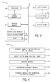
- the control and monitoring system 18 may be provided as a processor-based system, an example of which is depicted in FIG. 3 .
- the processor-based system 40 includes at least one processor 42 connected by a bus 44 to volatile memory 46 (e.g., random-access memory) and non-volatile memory 48 (e.g., flash memory).
- volatile memory 46 e.g., random-access memory
- non-volatile memory 48 e.g., flash memory
- Coded application instructions 50 and data 52 are stored in the non-volatile memory 48.
- the instructions 50 and the data 52 may also be loaded into the volatile memory 46 (or in a local memory 54 of the processor) as desired, such as to reduce latency and increase operating efficiency of the system 40.
- the coded application instructions 50 can be provided as software that may be executed by the processor 42 to enable various functionalities described herein, including analysis of signals received via the transducers 34 and 36 for casing cement evaluation.
- the system 18 may also be referred to as an analysis system.
- the application instructions 50 are encoded in a non-transitory, computer-readable storage medium, such as the volatile memory 46, the non-volatile memory 48, the local memory 54, or a portable storage device (e.g., a flash drive or a compact disc).
- An interface 56 of the system 40 enables communication between the processor 42 and various input devices 58 and output devices 60.
- the interface 56 can include any suitable device that enables such communication, such as a modem or a serial port.
- the input devices 58 include one or more sensing components of the downhole tool 12 (e.g., the transducers 34 and 36) and the output devices 60 include displays, printers, and storage devices that allow output of data received or generated by the system 40.
- the emitter i.e., transducer 32
- the emitter can send an oblique incident pulse exciting predominantly a zeroth-order anti-symmetric mode A0, also called the flexural mode, according to the way the energy propagates inside the wall of the pipe 24.
- A0 also called the flexural mode
- the acoustic wave leaks energy into both sides of the pipe wall and the amount of leakage depends on the material properties outside the pipe.
- an analysis of the recorded signals may provide valuable information to evaluate the cement quality.
- 2 t , t 0 ... T Strictly speaking, the terminology of symmetric SO and anti-symmetric AO modes refers just to attenuation-free plate waves (Lamb waves) in vacuum, but the present disclosure adopts the convention of labeling those waves whose real wavenumbers follow the corresponding classical Lamb plate waves by the same mode names (SO and AO).
- the tool 12 excites predominantly the zeroth-order symmetric mode S0, also called the extensional mode.
- This extensional mode is typically excited with a pulse center frequency lower that that used for exciting the AO mode.
- the choice of mode, AO versus S0 may be governed by considerations of spatial resolution, attenuation in the fluid, and sensitivity to the elastic properties of the cement.
- the measured signal can be represented again in the form of the weighted sum of equation (2).
- the results of dispersion relations for fluid-coupled plate waves can be used as approximations for the analysis of tube modes with a fluid- or solid-coupled external interface.
- the tool 12 emits an incident pulse from the transducer 32 toward the pipe 24 and concurrently excites both the zeroth-order anti-symmetric (flexural) mode AO and the zeroth-order symmetric (extensional) mode SO in the pipe 24.
- the emitted pulse is centered on a frequency of 20 kHz to 400 kHz (and is centered on a frequency of 250 kHz in at least one embodiment).
- the configuration of the tool 12 can be adjusted to favor one mode over the other, but in some cases the adjustment cannot completely annihilate one of the two modes because of the tool operational range.
- the signal may be processed in any suitable manner to separate these two modes.
- a quality factor Q-factor
- quality factor is estimated (block 72) for each of the AO (flexural) and SO (extensional) modes.
- quality factor is defined as the center-frequency-to-bandwidth ratio.
- the Q-factor for each mode can be computed from the dispersion characteristics of the individual modes and the ultrasonic transducer pulse spectrum.
- a filter bank is then created for each individual mode (block 74), with the design of the filter banks taking into account the quality factors and the dispersion characteristics of the individual modes.
- Signals may then be acquired (block 76), such as by either or both of transducers 34 and 36, and then decomposed (block 78) into series of coefficients using analysis filters of the filter banks.
- the separation of the signals into individual AO and SO signals (block 80) is then obtained by minimizing the error between the original signals and the sum of reconstructed individual signals, where the reconstructed individual signals can be provided as output of the synthesis filters applied to the optimized coefficients.
- the separation technique includes selecting a subset of coefficients produced by filtering via the first filter bank and a subset of coefficients produced by filtering via the second filter bank, such as by applying a threshold to discard lower-level coefficients.
- the selected subsets of coefficients can then be used to predict extensional mode and flexural mode waveforms that are based on the estimated quality factors for the individual modes. This prediction can include fitting a sum of reconstructed extensional mode and flexural mode waveforms to the acquired acoustic signal. Additional details regarding such processing are provided below.
- the frames F 1 and F 2 are respectively adapted to the Q-factor of AO and S0, as the Q-factor is a discriminant factor of zeroth-order Lamb modes signals.
- the Q-factor can be estimated by the signal bandwidth evaluated at - 6 dB below the maximum spectrum amplitude.
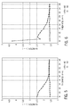
- FIGS. 5 and 6 show AO and SO mode Q-factors for the near ( FIG. 5 ) and far ( FIG. 6 ) receivers at one particular incident angle (28 degrees) in the tool configuration of FIG. 2 . While the Q-factors are given in FIGS. 5 and 6 for one particular incident angle, other incident angles may be used by the tool 12 and the Q-factors may differ in other embodiments. In general, the difference of Q-factor is more than 0.1 below 18 mm and close to 0 above 18 mm.
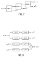
- FIG. 8 One example of a perfect reconstruction oversampled filter bank is generally represented in FIG. 8 , while iterative filtering using the filter bank is generally represented in FIG. 7 .
- the filter 8 includes an analysis filter bank (with analysis filters H 0 and H 1 ) shown in the top half of the figure and a synthesis filter bank (with synthesis filters H 0 * and H 1 *) shown in the bottom half.
- the filters H 0 and H 1 are also functions of the parameters ⁇ and ⁇ , such that ⁇ + ⁇ > 1, hence the oversampled characteristic.
- the blocks LPS and HPS are low-pass and high-pass scaling, and the subband signals v 0 and v 1 have sampling rates of ⁇ f s and ⁇ f s , respectively.
- Iterated filter bank decomposition is generally depicted in FIG. 7 , in which each stage includes the analysis filter bank depicted in FIG. 8 . It will be appreciated that iterated filter bank reconstruction may be generally represented as the reverse of the iterated decomposition.
- the first term (l 2 norm) is a fidelity term, ensuring that the decomposition has a small residual.
- the two other terms (l 1 norms) ensure that the components have a sparse representation in their respective frames.
- tiling of the time-frequency plane is depicted in FIG. 9 for a Q-factor of 2.8 and an oversampling rate r of 3.1. For clarity, just some of the tiles are shown. With zero-phase filters H 0 and H 1 in FIG. 8 , the main axes of the tiles are either vertical or horizontal, as generally shown by the arrows in the detail view of FIG. 10 . This regular tiling is not well suited to decompose dispersive signals.
- l pipe is the propagation distance in the pipe (e.g., casing 24)
- ⁇ mud is the propagation time
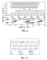
- the parameter ⁇ rotates the main axes of the tiles by a certain angle.
- the decomposition will locally match the slope of the group delay curve. Examples of theoretical group delay curves for both AO and SO modes for a particular pipe thickness of 16 mm are depicted in FIG. 13 . While both filters can be adapted to a group delay curve, in one implementation it is just the filter H 1 that is adapted to the group delay curve.
- the AO and SO signals may be separated in any suitable manner.
- Another example of a method for separating such signals is generally represented by flowchart 90 in FIG. 14 .
- the presently represented method includes various inputs, such as a waveform y of N samples (block 92), which may be detected via transducer 34 or 36 as a result of the excitation of a multi-modal Lamb wave excited in the pipe 24, as described above.
- Inputs may also include estimated quality factors Q 1 and Q 2 (block 94) for AO and SO waves, respectively; oversampling rates r 1 and r 2 (block 96) for AO and SO waves, respectively; and a desired number of iterations N it for signal decomposition (block 98).
- the method can also include computing phase and group velocity curves (via equations (9) and (10), for instance), as represented in block 106, as well as computing travel time ( ⁇ mud ) of an acoustic signal in a drilling mud or other logging fluid in the pipe 24, as represented in block 108.
- the filters may be defined based on estimated Q-factors for the AO and SO waves, as described above.
- a comparison of synthetic A0 and SO waves (i.e., simulated single-mode signals) with AO and SO waves reconstructed in accordance with the present techniques is depicted in the lower two plots of FIG. 15 , while the uppermost plot in FIG. 15 compares synthetic and reconstructed composites of the AO and SO waves.
Landscapes
- Life Sciences & Earth Sciences (AREA)
- Physics & Mathematics (AREA)
- Engineering & Computer Science (AREA)
- Geology (AREA)
- General Life Sciences & Earth Sciences (AREA)
- Environmental & Geological Engineering (AREA)
- Geophysics (AREA)
- Mining & Mineral Resources (AREA)
- Acoustics & Sound (AREA)
- Remote Sensing (AREA)
- General Physics & Mathematics (AREA)
- Fluid Mechanics (AREA)
- Quality & Reliability (AREA)
- Geochemistry & Mineralogy (AREA)
- Investigating Or Analyzing Materials By The Use Of Ultrasonic Waves (AREA)
Abstract
Methods for separating flexural and extensional mode signals from a multi-modal signal are provided. In one embodiment, a method includes emitting an ultrasonic pulse to excite a multi-modal Lamb wave in a pipe and then detecting acoustic signals generated from the Lamb wave. The detected acoustic signals are processed to separate the extensional and flexural mode signals. This processing can include filtering the detected acoustic signals with filters that are based on quality factors and dispersion characteristics for the individual modes to produce sets of coefficients, selecting subsets of the coefficients, and using the selected subsets to predict extensional and flexural mode waveforms that are based on the estimated quality factors for the individual modes. Additional methods, systems, and devices are also disclosed.
Description
- Wells are generally drilled into subsurface rocks to access fluids, such as hydrocarbons, stored in subterranean formations. The formations penetrated by a well can be evaluated for various purposes, including for identifying hydrocarbon reservoirs within the formations. During drilling operations, one or more drilling tools in a drill string may be used to test or sample the formations. Following removal of the drill string, a wireline tool may also be run into the well to test or sample the formations. These drilling tools and wireline tools, as well as other wellbore tools conveyed on coiled tubing, slickline, drill pipe, casing or other means of conveyance, are also referred to herein as "downhole tools." A downhole tool may be employed alone or in combination with other downhole tools in a downhole tool string.
- As will be appreciated, casing may be run into the well for structural support and for isolating fluids within the wellbore from certain formations (e.g., freshwater reservoirs) penetrated by the well. The casing can be cemented into place within the well. A cement job includes the design and the pumping of a cement slurry inside the well, with the objective of the right cement slurry placement. During a cement job, the cement slurry can be pumped down a casing string in a well, out the bottom of the casing string, and then up the annular space surrounding the casing string. The cement is then allowed to set in the annular space. Various parameters can have a negative impact on the success of a cement job, such as contamination of the cement slurry by drilling mud or poor centralization of the casing within the well. After the cement slurry is pumped into the annulus between the casing and the formation, a downhole tool (e.g., an acoustic logging tool) may be run into the cased well for evaluating the quality of the cement around the casing.
- Certain aspects of some embodiments disclosed herein are set forth below. It should be understood that these aspects are presented merely to provide the reader with a brief summary of certain forms the invention might take and that these aspects are not intended to limit the scope of the invention. Indeed, the invention may encompass a variety of aspects that may not be set forth below.
- As described in greater detail below, at least some embodiments of the present disclosure relate to separation of flexural and extensional mode components of a multi-modal acoustic signal, such as may be received by an acoustic logging tool performing cement evaluation. In one embodiment, a method includes emitting an ultrasonic pulse toward a casing within a well so as to excite a multi-modal Lamb wave within the casing, the multi-modal Lamb wave having flexural and extensional modes. The method also includes detecting acoustic signals generated by the multi-modal Lamb wave within the casing, and processing the detected acoustic signals to separate acoustic signals generated by the extensional mode from acoustic signals generated by the flexural mode. This processing includes filtering the detected acoustic signals with a first filter bank that filters the detected acoustic signals based on an estimated quality factor for the extensional mode and on dispersion characteristics of the extensional mode to produce a first set of coefficients. The processing also includes filtering the detected acoustic signals with a second filter bank that filters the detected acoustic signals based on an estimated quality factor for the flexural mode and on dispersion characteristics of the flexural mode to produce a second set of coefficients. Additionally, the processing includes selecting subsets of the first and second sets of coefficients and using the selected subsets of coefficients to predict an extensional mode waveform and a flexural mode waveform based on the estimated quality factors for the extensional and flexural modes.
- In another embodiment, a method includes emitting an ultrasonic pulse so as to excite a multi-modal Lamb wave having flexural and extensional modes within a pipe and receiving acoustic signals generated by the multi-modal Lamb wave. The method also includes calculating phase velocity and group velocity curves for each of the flexural and extensional modes, as well as calculating a group delay time for each of the flexural and extensional modes. Further, the method includes defining filters based on estimated quality factors for the flexural and extensional modes, decomposing the received acoustic signals via the defined filters, and reconstructing estimates of flexural and extensional wave components of the multi-modal Lamb wave based on the decomposition of the received acoustic signals.
- In an additional embodiment, an apparatus includes a downhole tool for acquiring data within a well. The downhole tool includes an acoustic transmitter and an acoustic receiver, which are positioned to allow the acoustic transmitter to emit acoustic signals outwardly from the downhole tool to generate a Lamb wave having flexural and extensional modes in a casing in the well and to allow the acoustic receiver to detect the Lamb wave when the downhole tool is positioned inside the casing. The apparatus also includes an analysis system for receiving data from the downhole tool and separating concurrent flexural and extensional mode components of the detected Lamb wave using quality factors for the flexural and extensional modes.
- Various refinements of the features noted above may exist in relation to various aspects of the present embodiments. Further features may also be incorporated in these various aspects. These refinements and additional features may exist individually or in any combination. For instance, various features discussed below in relation to the illustrated embodiments may be incorporated into any of the above-described aspects of the present disclosure alone or in any combination. Again, the brief summary presented above is intended just to familiarize the reader with certain aspects and contexts of some embodiments without limitation to the claimed subject matter.
- These and other features, aspects, and advantages of certain embodiments will become better understood when the following detailed description is read with reference to the accompanying drawings in which like characters represent like parts throughout the drawings, wherein:
-
FIG. 1 generally depicts a downhole tool deployed within a well on a wireline in accordance with one embodiment of the present disclosure; -
FIG. 2 represents the downhole tool ofFIG. 1 as an acoustic logging tool having obliquely arranged transducers for inducing a Lamb wave within a casing and measuring resulting acoustic signals in accordance with one embodiment; -
FIG. 3 is a block diagram of components of a processor-based system that can be used to perform certain monitoring or control operations, such as analysis of data acquired via the acoustic logging tool ofFIG. 2 , in accordance with one embodiment; -
FIG. 4 is a flowchart representing a process for separating concurrent flexural and extensional modes in an acoustic signal in accordance with one embodiment; -
FIGS. 5 and 6 are graphs showing quality factors for flexural and extensional modes in accordance with one embodiment; -
FIG. 7 generally depicts an iterative filtering of an acoustic signal in accordance with one embodiment; -
FIG. 8 depicts an oversampled filter bank having analysis filters and synthesis filters in accordance with one embodiment; -
FIGS. 9 and 10 depict tiling of a time-frequency plane for a given quality factor and oversampling rate in accordance with one embodiment; -
FIGS. 11 and 12 depict tiling of the time-frequency plane for the given quality factor and oversampling rate ofFIGS. 9 and 10 , but with the axes of the tiles rotated based on a group delay derivative in accordance with one embodiment; -
FIG. 13 depicts theoretical group delay curves for extensional and flexural modes for a pipe in accordance with one embodiment; -
FIG. 14 is a flowchart representing another process for separating concurrent flexural and extensional modes in a signal in accordance with one embodiment; and -
FIG. 15 is a comparison of reconstructed single-mode extensional and flexural waves and a composite multi-modal wave to synthetic waves in accordance with one embodiment. - It is to be understood that the present disclosure provides many different embodiments, or examples, for implementing different features of various embodiments. Specific examples of components and arrangements are described below for purposes of explanation and to simplify the present disclosure. These are, of course, merely examples and are not intended to be limiting.
- When introducing elements of various embodiments, the articles "a," "an," "the," and "said" are intended to mean that there are one or more of the elements. The terms "comprising," "including," and "having" are intended to be inclusive and mean that there may be additional elements other than the listed elements. Moreover, any use of "top," "bottom," "above," "below," other directional terms, and variations of these terms is made for convenience, but does not mandate any particular orientation of the components.
- The present disclosure generally relates to acoustic tools, such as acoustic logging tools that may be used to evaluate cement about a casing in a well. More particularly, at least some embodiments relate to a technique for processing signals acquired by ultrasonic cement evaluation tools. In certain embodiments, the signals are ultrasonic multi-modal guided waves and the signals are separated into a sum of individual signals of zeroth-order symmetric and antisymmetric Lamb modes to improve the quantitative interpretation of measurements.
- Turning now to the drawings, an
apparatus 10 for evaluating cement quality in a well is depicted inFIG. 1 in accordance with one embodiment. In this depicted embodiment, adownhole tool 12 is suspended in awell 14 on acable 16. Thecable 16 may be a wireline cable with at least one conductor that enables data transmission between thedownhole tool 12 and a monitoring andcontrol system 18. Thecable 16 may be raised and lowered within thewell 14 in any suitable manner. For instance, thecable 16 can be reeled from a drum in a service truck, which may be a logging truck having the monitoring andcontrol system 18. Although thedownhole tool 12 is depicted inFIG. 1 as being deployed via a cable, thedownhole tool 12 could be deployed within thewell 14 in any other suitable manner. Further, while theapparatus 10 is shown inFIG. 1 at anonshore well 14, it will be appreciated that theapparatus 10 could be used with an offshore well in full accordance with the present techniques. - The monitoring and
control system 18 controls movement of thedownhole tool 12 within the well 14 and receives data from thedownhole tool 12. The monitoring andcontrol system 18 can include one or more computer systems or devices. Thesystem 18 can receive data from thedownhole tool 12, and this data can be stored, communicated to an operator, or processed. Although generally depicted inFIG. 1 at a wellsite, it is noted that thesystem 18 could be positioned elsewhere, and that thesystem 18 could be a distributed system with elements provided at different places near or remote from thewell 14. For example, a local component of thesystem 18 may be located at the wellsite for controlling operation of thedownhole tool 12 and receiving data from thetool 12, but the received data could be processed by a different portion of thesystem 18 at another location. - The
downhole tool 12 can take various forms, one example of which is depicted inFIG. 2 as an acoustic logging tool lowered within acasing 24 in thewell 14.Cement 26 is provided in an annular space between the casing 24 (which may also be referred to as pipe 24) and aformation 28 penetrated by thewell 14. The acoustic logging tool includestransducers FIG. 2 , thetransducer 32 operates as an emitter (and may accordingly be referred to as an acoustic transmitter or an ultrasonic transmitter), while thetransducers transducer 32, thetransducer 34 may also be referred to as the "near" receiver and thetransducer 36 may be referred to as the "far" receiver. - As described in greater detail below, the
transducer 32 can emit an ultrasonic pulse toward thecasing 24 so as to excite a multi-modal Lamb wave within thecasing 24, whiletransducers transducers transducer 32 may be angled toward thetransducers transducers transducer 32 at that angle of incidence. In at least one embodiment, the angle of incidence is selected so as to optimize the excitation and detection of a particular mode (e.g., a flexural mode) of the Lamb wave in thecasing 24. The signals measured with thetransducers cement 26 about thecasing 24. Consequently, the acoustic logging tool ofFIG. 2 may also be referred to as a cement evaluation tool. Data acquired with thetransducers control system 18 at the surface via awireline cable 16 in at least some embodiments. The data could also or instead be stored in a local memory device within thetool 12 for later collection. - The control and
monitoring system 18 may be provided as a processor-based system, an example of which is depicted inFIG. 3 . As presently shown, the processor-basedsystem 40 includes at least oneprocessor 42 connected by abus 44 to volatile memory 46 (e.g., random-access memory) and non-volatile memory 48 (e.g., flash memory).Coded application instructions 50 anddata 52 are stored in thenon-volatile memory 48. Theinstructions 50 and thedata 52 may also be loaded into the volatile memory 46 (or in alocal memory 54 of the processor) as desired, such as to reduce latency and increase operating efficiency of thesystem 40. Thecoded application instructions 50 can be provided as software that may be executed by theprocessor 42 to enable various functionalities described herein, including analysis of signals received via thetransducers system 18 may also be referred to as an analysis system. In at least some embodiments, theapplication instructions 50 are encoded in a non-transitory, computer-readable storage medium, such as thevolatile memory 46, thenon-volatile memory 48, thelocal memory 54, or a portable storage device (e.g., a flash drive or a compact disc). - An
interface 56 of thesystem 40 enables communication between theprocessor 42 andvarious input devices 58 andoutput devices 60. Theinterface 56 can include any suitable device that enables such communication, such as a modem or a serial port. In some embodiments, theinput devices 58 include one or more sensing components of the downhole tool 12 (e.g., thetransducers 34 and 36) and theoutput devices 60 include displays, printers, and storage devices that allow output of data received or generated by thesystem 40. - As generally noted above, various approaches can be used for cement evaluation using Lamb waves. By way of example, in the tool configuration depicted in
FIG. 2 , the emitter (i.e., transducer 32) can send an oblique incident pulse exciting predominantly a zeroth-order anti-symmetric mode A0, also called the flexural mode, according to the way the energy propagates inside the wall of thepipe 24. When propagating along thepipe 24, the acoustic wave leaks energy into both sides of the pipe wall and the amount of leakage depends on the material properties outside the pipe. Hence an analysis of the recorded signals may provide valuable information to evaluate the cement quality. One example of the analyzed quantities is the flexural attenuation (expressed in dB/m), defined as the ratio of signal amplitudes on both receivers (i.e.,transducers 34 and 36)

- In another approach, the
tool 12 excites predominantly the zeroth-order symmetric mode S0, also called the extensional mode. This extensional mode is typically excited with a pulse center frequency lower that that used for exciting the AO mode. The choice of mode, AO versus S0, may be governed by considerations of spatial resolution, attenuation in the fluid, and sensitivity to the elastic properties of the cement. In analogy to the flexural mode approach, the measured signal can be represented again in the form of the weighted sum of equation (2). The results of dispersion relations for fluid-coupled plate waves can be used as approximations for the analysis of tube modes with a fluid- or solid-coupled external interface. This allows for the use of asymptotic wave mode solutions for each of the modes, AO and S0, separately. The neglect of the shear-wave degree of freedom in the solid can yield results for the leaky tube modes with effective attenuation coefficients that lump together the shear- and compressional-wave attenuation pathways. - In another approach, the
tool 12 emits an incident pulse from thetransducer 32 toward thepipe 24 and concurrently excites both the zeroth-order anti-symmetric (flexural) mode AO and the zeroth-order symmetric (extensional) mode SO in thepipe 24. In at least some embodiments, the emitted pulse is centered on a frequency of 20 kHz to 400 kHz (and is centered on a frequency of 250 kHz in at least one embodiment). The configuration of thetool 12 can be adjusted to favor one mode over the other, but in some cases the adjustment cannot completely annihilate one of the two modes because of the tool operational range. Although thetool 12 is depicted inFIG. 2 as having two receivingtransducers transducers tool 12 could be operated with a single receiving transducer for detecting acoustic signals resulting from the pulse emitted by thetransducer 32. Further, while certain embodiments are described herein with respect to a multi-modal signal excited in acasing 24 and a downhole tool within a well, it will be appreciated that in other embodiments the presently disclosed analysis techniques may also or instead be used in other pipes that are not within a well and with other tools that are not downhole tools. - In embodiments in which the detected signal is a composite of two distinct Lamb mode signals (e.g., concurrent flexural and extensional modes), the signal may be processed in any suitable manner to separate these two modes. One example of such processing is generally represented by
flowchart 70 inFIG. 4 . In this embodiment, a quality factor (Q-factor) is estimated (block 72) for each of the AO (flexural) and SO (extensional) modes. As will be appreciated, quality factor is defined as the center-frequency-to-bandwidth ratio. The Q-factor for each mode can be computed from the dispersion characteristics of the individual modes and the ultrasonic transducer pulse spectrum. - A filter bank is then created for each individual mode (block 74), with the design of the filter banks taking into account the quality factors and the dispersion characteristics of the individual modes. Signals may then be acquired (block 76), such as by either or both of
transducers - By way of explanation, it may be assumed, as a first approximation, that the acquired signal is the sum of two distinct, zeroth-order Lamb modes signals


FIGS. 5 and 6 show AO and SO mode Q-factors for the near (FIG. 5 ) and far (FIG. 6 ) receivers at one particular incident angle (28 degrees) in the tool configuration ofFIG. 2 . While the Q-factors are given inFIGS. 5 and 6 for one particular incident angle, other incident angles may be used by thetool 12 and the Q-factors may differ in other embodiments. In general, the difference of Q-factor is more than 0.1 below 18 mm and close to 0 above 18 mm. - Given the Q-factors of AO and S0, the frames F 1 and F 2 can be given by an iterated perfect reconstruction oversampled filter bank, which can include analysis and synthesis filter banks. Both the analysis and the synthesis filters can be defined using the Q-factor and the oversampling rate r

FIG. 8 , while iterative filtering using the filter bank is generally represented inFIG. 7 . The filter bank ofFIG. 8 includes an analysis filter bank (with analysis filters H0 and H1) shown in the top half of the figure and a synthesis filter bank (with synthesis filters H0* and H1*) shown in the bottom half. The filters H0 and H1 are also functions of the parameters α and β, such that α + β > 1, hence the oversampled characteristic. The blocks LPS and HPS are low-pass and high-pass scaling, and the subband signals v 0 and v 1 have sampling rates of αfs and βfs , respectively. Iterated filter bank decomposition is generally depicted inFIG. 7 , in which each stage includes the analysis filter bank depicted inFIG. 8 . It will be appreciated that iterated filter bank reconstruction may be generally represented as the reverse of the iterated decomposition. - The two components can be estimated by solving the following
minimization problem 


- The problem (6) can be rewritten as an optimization problem under constraints



- By way of example, tiling of the time-frequency plane is depicted in
FIG. 9 for a Q-factor of 2.8 and an oversampling rate r of 3.1. For clarity, just some of the tiles are shown. With zero-phase filters H 0 and H 1 inFIG. 8 , the main axes of the tiles are either vertical or horizontal, as generally shown by the arrows in the detail view ofFIG. 10 . This regular tiling is not well suited to decompose dispersive signals. Indeed, both Lamb modes exhibit dispersion which means that the phase and group velocities depend on the frequency


FIGS. 11 and 12 using a fixed γ = 35, with the Q-factor remaining 2.8 and the oversampling rate r remaining 3.1. (Again, just some of the tiles are shown here for clarity.) As a consequence, the decomposition will locally match the slope of the group delay curve. Examples of theoretical group delay curves for both AO and SO modes for a particular pipe thickness of 16 mm are depicted inFIG. 13 . While both filters can be adapted to a group delay curve, in one implementation it is just the filter H 1 that is adapted to the group delay curve. - As noted above, the AO and SO signals may be separated in any suitable manner. Another example of a method for separating such signals is generally represented by
flowchart 90 inFIG. 14 . The presently represented method includes various inputs, such as a waveform y of N samples (block 92), which may be detected viatransducer pipe 24, as described above. Inputs may also include estimated quality factors Q 1 and Q 2 (block 94) for AO and SO waves, respectively; oversampling rates r 1 and r 2 (block 96) for AO and SO waves, respectively; and a desired number of iterations Nit for signal decomposition (block 98). - The method can include computing αi and βi , i = 1,2 (e.g., using equation (5)), as represented in
block 102, and solving Rayleigh-Lamb equations using asymptotic code, as represented inblock 104. The method can also include computing phase and group velocity curves (via equations (9) and (10), for instance), as represented inblock 106, as well as computing travel time (δmud ) of an acoustic signal in a drilling mud or other logging fluid in thepipe 24, as represented inblock 108. Additionally, the method represented byflowchart 90 includes computing group delay (δm ) over a distance l pipe (e.g., using equation (13)) and computing a derivative of the group delay (e.g., ∂δm (ω)/∂ω, m = A0,S0), as represented inblocks - Further, the method can include defining filters H̃ 1,i (ω), i = 1,2 with parameter γ (e.g., using equation (11)), as represented in
block 114. It will be appreciated that the filters may be defined based on estimated Q-factors for the AO and SO waves, as described above. Further still, the method can include decomposing the acquired waveform via the defined filters, which can include solving an optimization problem (block 116), such as equation (8), in Nit iterations. Then, from the final


FIG. 15 , while the uppermost plot inFIG. 15 compares synthetic and reconstructed composites of the AO and SO waves. - The foregoing outlines features of several embodiments so that those skilled in the art may better understand aspects of the present disclosure. Those skilled in the art should appreciate that they may readily use the present disclosure as a basis for designing or modifying other processes and structures for carrying out the same purposes or achieving the same advantages of the embodiments introduced herein. Those skilled in the art should also realize that such equivalent constructions do not depart from the spirit and scope of the present disclosure, and that they may make various changes, substitutions and alterations herein without departing from the spirit and scope of the present disclosure.
Claims (15)
- A method comprising:emitting an ultrasonic pulse, from an acoustic logging tool within a well, toward a casing within the well so as to excite a multi-modal Lamb wave within the casing, the multi-modal Lamb wave having flexural and extensional modes;detecting, with the acoustic logging tool, acoustic signals generated by the multi-modal Lamb wave within the casing; andprocessing the detected acoustic signals to separate acoustic signals generated by the extensional mode from acoustic signals generated by the flexural mode, wherein processing the detected acoustic signals to separate the acoustic signals generated by the extensional mode from the acoustic signals generated by the flexural mode includes:filtering the detected acoustic signals with a first filter bank having one or more filters that filter the detected acoustic signals based on an estimated quality factor for the extensional mode and on dispersion characteristics of the extensional mode to produce a first set of coefficients;filtering the detected acoustic signals with a second filter bank having one or more filters that filter the detected acoustic signals based on an estimated quality factor for the flexural mode and on dispersion characteristics of the flexural mode to produce a second set of coefficients;selecting a subset of the first set of coefficients and a subset of the second set of coefficients; andusing the selected subsets of coefficients to predict an extensional mode waveform and a flexural mode waveform based on the estimated quality factors for the extensional and flexural modes.
- The method of claim 1, comprising:computing the estimated quality factor for the extensional mode based on dispersion characteristics of the extensional mode and on the spectrum of the ultrasonic pulse; andcomputing the estimated quality factor for the flexural mode based on dispersion characteristics of the flexural mode and on the spectrum of the ultrasonic pulse.
- The method of claim 1 or claim 2, wherein filtering the detected acoustic signals with the first filter bank and filtering the detected acoustic signals with the second filter bank include filtering the detected acoustic signals with decomposition filters.
- The method of claim 3, wherein at least one of the decomposition filters of the first filter bank includes a group delay parameter for the extensional mode.
- The method of claim 4, wherein at least one of the decomposition filters of the second filter bank includes a group delay parameter for the flexural mode.
- The method of any of claims 1 to 5, wherein using the selected subsets of coefficients to predict the extensional mode waveform and the flexural mode waveform includes fitting a sum of a reconstructed extensional mode waveform and a reconstructed flexural mode waveform to the detected acoustic signal.
- The method of any of claims 1 to 6, wherein selecting the subsets of the first and second sets of coefficients includes applying a threshold to discard lower-level coefficients.
- The method of any of claims 1 to 7, wherein emitting the ultrasonic pulse toward the casing includes emitting an ultrasonic pulse with a central frequency between 20 kHz and 400 kHz.
- The method of any of claims 1 to 8, comprising using the predicted flexural mode waveform to evaluate cement provided about an exterior of the casing.
- An apparatus comprising:a downhole tool that facilitates data acquisition within a well, the downhole tool including an acoustic transmitter and an acoustic receiver, wherein the acoustic transmitter and the acoustic receiver are positioned with respect to one another so as to enable the acoustic transmitter to emit acoustic signals outwardly from the downhole tool toward a casing within the well to generate a Lamb wave having flexural and extensional modes in the casing and to enable the acoustic receiver to detect the Lamb wave when the downhole tool is positioned inside the casing;an analysis system configured to receive data from the downhole tool and to separate concurrent flexural and extensional mode components of the detected Lamb wave using quality factors for the flexural and extensional modes.
- The apparatus of claim 10, wherein the acoustic transmitter and the acoustic receiver are angled toward one another at a shared angle of incidence.
- The apparatus of claim 10 or claim 11, wherein the acoustic transmitter includes an ultrasonic transmitter and the acoustic receiver includes an ultrasonic receiver.
- The apparatus of any of claims 10 to 12, wherein the downhole tool is positioned inside the casing.
- The apparatus of any of claims 10 to 13, wherein the downhole tool includes at least one additional acoustic receiver positioned to enable the additional acoustic receiver to detect the Lamb wave when the downhole tool is positioned inside the casing.
- The apparatus of any of claims 10 to 14, wherein the downhole tool is a wireline tool.
Priority Applications (2)
| Application Number | Priority Date | Filing Date | Title |
|---|---|---|---|
| EP16306114.6A EP3290961A1 (en) | 2016-09-06 | 2016-09-06 | Separation of flexural and extensional modes in multi modal acoustic signals |
| US15/691,808 US20180067223A1 (en) | 2016-09-06 | 2017-08-31 | Separation of flexural and extensional modes in multi modal acoustic signals |
Applications Claiming Priority (1)
| Application Number | Priority Date | Filing Date | Title |
|---|---|---|---|
| EP16306114.6A EP3290961A1 (en) | 2016-09-06 | 2016-09-06 | Separation of flexural and extensional modes in multi modal acoustic signals |
Publications (1)
| Publication Number | Publication Date |
|---|---|
| EP3290961A1 true EP3290961A1 (en) | 2018-03-07 |
Family
ID=56939983
Family Applications (1)
| Application Number | Title | Priority Date | Filing Date |
|---|---|---|---|
| EP16306114.6A Withdrawn EP3290961A1 (en) | 2016-09-06 | 2016-09-06 | Separation of flexural and extensional modes in multi modal acoustic signals |
Country Status (2)
| Country | Link |
|---|---|
| US (1) | US20180067223A1 (en) |
| EP (1) | EP3290961A1 (en) |
Cited By (3)
| Publication number | Priority date | Publication date | Assignee | Title |
|---|---|---|---|---|
| CN109409194A (en) * | 2018-08-30 | 2019-03-01 | 中国航发湖南动力机械研究所 | Multi-modal time-domain signal modal separation, damping parameter discrimination method and storage medium |
| EP3995865A1 (en) * | 2020-11-06 | 2022-05-11 | Services Pétroliers Schlumberger | Automatic recognition of environmental parameters with azimuthally distributed transducers |
| CN116399960A (en) * | 2023-04-20 | 2023-07-07 | 江苏大学 | Actual measurement method of broadband laser ultrasonic Lamb wave attenuation coefficient in metal sheet |
Families Citing this family (8)
| Publication number | Priority date | Publication date | Assignee | Title |
|---|---|---|---|---|
| CN108921113A (en) * | 2018-07-10 | 2018-11-30 | 南京信息工程大学 | Multi-mode Lamb wave signal separating method based on fractional order differential |
| CN110333285B (en) * | 2019-07-04 | 2021-07-27 | 大连海洋大学 | Ultrasonic Lamb Wave Defect Signal Identification Method Based on Variational Mode Decomposition |
| GB2592974A (en) * | 2020-03-12 | 2021-09-15 | Equanostic As | Method for differentiating materials on a remote side of a partition based on the attenuation of the ultrasonic extensional zero mode |
| GB2609627A (en) | 2021-08-09 | 2023-02-15 | Equanostic As | Method for determining if a wellbore consists of micro annulus, free pipe or solid bonding between the wellbore and a casing |
| CN115992690B (en) * | 2023-03-24 | 2023-06-06 | 中海油田服务股份有限公司 | Ultrasonic lamb wave imaging logging device while drilling and logging method |
| US12270296B2 (en) * | 2023-08-03 | 2025-04-08 | Halliburton Energy Services, Inc. | Cement evaluation |
| US20250179916A1 (en) * | 2023-11-30 | 2025-06-05 | Halliburton Energy Services, Inc. | Computing A0 Mode Attenuation For Cement Evaluation In Cased Wells |
| US20250305406A1 (en) * | 2024-03-26 | 2025-10-02 | Halliburton Energy Services, Inc. | Cement Evaluation With Coated Pipe |
Citations (3)
| Publication number | Priority date | Publication date | Assignee | Title |
|---|---|---|---|---|
| US20090067286A1 (en) * | 2007-09-12 | 2009-03-12 | Schlumberger Technology Corporation | Dispersion extraction for acoustic data using time frequency analysis |
| US20120069705A1 (en) * | 2008-11-10 | 2012-03-22 | Baker Hughes Incorporated | EMAT Acoustic Signal Measurement Using Modulated Gaussian Wavelet and Hilbert Demodulation |
| US20160209539A1 (en) * | 2014-11-14 | 2016-07-21 | Schlumberger Technology Corporation | Method for Separating Multi-Modal Acoustic Measurements for Evaluating Multilayer Structures |
Family Cites Families (5)
| Publication number | Priority date | Publication date | Assignee | Title |
|---|---|---|---|---|
| DE60301734D1 (en) * | 2003-08-08 | 2006-02-09 | Schlumberger Technology Bv | Multimodal acoustic imaging in cased boreholes |
| DE602004011678D1 (en) * | 2004-12-20 | 2008-03-20 | Schlumberger Technology Bv | Determine the impedance of a material behind a casing by combining two sets of ultrasonic measurements |
| US9115568B2 (en) * | 2009-09-29 | 2015-08-25 | Schlumberger Technology Corporation | Reduction of tool mode and drilling noise in acoustic LWD |
| US9927541B2 (en) * | 2014-04-15 | 2018-03-27 | Schlumberger Technology Corporation | Apparatus for monopole and multipole sonic logging of a downhole formation |
| US9732607B2 (en) * | 2014-08-18 | 2017-08-15 | Schlumberger Technology Corporation | Methods and apparatus for evaluating properties of cement utilizing ultrasonic signal testing |
-
2016
- 2016-09-06 EP EP16306114.6A patent/EP3290961A1/en not_active Withdrawn
-
2017
- 2017-08-31 US US15/691,808 patent/US20180067223A1/en not_active Abandoned
Patent Citations (3)
| Publication number | Priority date | Publication date | Assignee | Title |
|---|---|---|---|---|
| US20090067286A1 (en) * | 2007-09-12 | 2009-03-12 | Schlumberger Technology Corporation | Dispersion extraction for acoustic data using time frequency analysis |
| US20120069705A1 (en) * | 2008-11-10 | 2012-03-22 | Baker Hughes Incorporated | EMAT Acoustic Signal Measurement Using Modulated Gaussian Wavelet and Hilbert Demodulation |
| US20160209539A1 (en) * | 2014-11-14 | 2016-07-21 | Schlumberger Technology Corporation | Method for Separating Multi-Modal Acoustic Measurements for Evaluating Multilayer Structures |
Non-Patent Citations (2)
| Title |
|---|
| RICCARDO BERNARDINI ET AL: "Arbitrary Tilings of the Time-Frequency Plane Using Local Bases", IEEE TRANSACTIONS ON SIGNAL PROCESSING, IEEE SERVICE CENTER, NEW YORK, NY, US, vol. 47, no. 8, 1 August 1999 (1999-08-01), XP011058646, ISSN: 1053-587X * |
| ROBERT VAN KUIJK ET AL: "A Novel Ultrasonic Cased-Hole Imager for Enhanced Cement Evaluation", PROCEEDINGS OF INTERNATIONAL PETROLEUM TECHNOLOGY CONFERENCE, 1 January 2005 (2005-01-01), XP055064256, ISBN: 978-1-55-563991-4, DOI: 10.2523/10546-MS * |
Cited By (5)
| Publication number | Priority date | Publication date | Assignee | Title |
|---|---|---|---|---|
| CN109409194A (en) * | 2018-08-30 | 2019-03-01 | 中国航发湖南动力机械研究所 | Multi-modal time-domain signal modal separation, damping parameter discrimination method and storage medium |
| CN109409194B (en) * | 2018-08-30 | 2020-12-01 | 中国航发湖南动力机械研究所 | Multimode time domain signal modal separation and damping parameter identification method and storage medium |
| EP3995865A1 (en) * | 2020-11-06 | 2022-05-11 | Services Pétroliers Schlumberger | Automatic recognition of environmental parameters with azimuthally distributed transducers |
| US11947064B2 (en) | 2020-11-06 | 2024-04-02 | Schlumberger Technology Corporation | Automatic recognition of environmental parameters with azimuthally distributed transducers |
| CN116399960A (en) * | 2023-04-20 | 2023-07-07 | 江苏大学 | Actual measurement method of broadband laser ultrasonic Lamb wave attenuation coefficient in metal sheet |
Also Published As
| Publication number | Publication date |
|---|---|
| US20180067223A1 (en) | 2018-03-08 |
Similar Documents
| Publication | Publication Date | Title |
|---|---|---|
| EP3290961A1 (en) | Separation of flexural and extensional modes in multi modal acoustic signals | |
| US20220351037A1 (en) | Method and system for spectroscopic prediction of subsurface properties using machine learning | |
| EP3179277B1 (en) | Resonance-based inversion of acoustic impedance of annulus behind casing | |
| US8243549B2 (en) | Estimating seismic anisotropy of shales | |
| GB2560228A (en) | Improved method of and apparatus for carrying out acoustic well logging | |
| US20160109603A1 (en) | Method and apparatus for characterizing elastic anisotropy for transversely isotropic unconventional shale | |
| US20110083844A1 (en) | Seismic Fluid Prediction Via Expanded AVO Anomalies | |
| WO2016187240A1 (en) | Method for analyzing cement integrity in cased wells using sonic logging | |
| US11163082B2 (en) | Real-time pattern recognition and automatic interpretation of acoustic reflection images | |
| CN106460507A (en) | Guided wave downhole fluid sensor | |
| US20190242221A1 (en) | Method to predict reservoir formation permeability using combined acoustic and multi-frequency dielectric measurements | |
| US10094945B2 (en) | Formation measurements using nonlinear guided waves | |
| US12523791B2 (en) | Randomly quantized seismic data reconstruction using LSTM network | |
| CA2946427A1 (en) | Determining shear slowness based on a higher order formation flexural acoustic mode | |
| US20180045845A1 (en) | Method and system for processing sonic data acquired with a downhole tool | |
| US20250003325A1 (en) | Method and system for predicting hydrocarbon data for unconventional reservoirs using machine learning | |
| US20180031722A1 (en) | Systems and methods employing a menu-based graphical user interface (gui) to derive a shear slowness log | |
| US20240376812A1 (en) | Enhancing Borehole Resonance Signal For Through Tubing Cement Evaluation | |
| US20250305406A1 (en) | Cement Evaluation With Coated Pipe | |
| US20250179916A1 (en) | Computing A0 Mode Attenuation For Cement Evaluation In Cased Wells | |
| US20260093055A1 (en) | Sequential residual symbolic regression for modeling formation evaluation and reservoir fluid parameters | |
| US20250223900A1 (en) | Borehole resonance mode for cement evaluation using machine learning | |
| US20260086258A1 (en) | Blue-Shift Of Resonance Frequency To Detect Fluid Channel Behind Cemented Casing | |
| US20250217631A1 (en) | Deep Learning System for Casing Centralization Estimation Through Pulse-Echo TIE Interference | |
| US20250243747A1 (en) | Ultra-Sonic Acoustic Method For Through Casing Cement Evaluation |
Legal Events
| Date | Code | Title | Description |
|---|---|---|---|
| PUAI | Public reference made under article 153(3) epc to a published international application that has entered the european phase |
Free format text: ORIGINAL CODE: 0009012 |
|
| AK | Designated contracting states |
Kind code of ref document: A1 Designated state(s): AL AT BE BG CH CY CZ DE DK EE ES FI FR GB GR HR HU IE IS IT LI LT LU LV MC MK MT NL NO PL PT RO RS SE SI SK SM TR |
|
| AX | Request for extension of the european patent |
Extension state: BA ME |
|
| STAA | Information on the status of an ep patent application or granted ep patent |
Free format text: STATUS: THE APPLICATION IS DEEMED TO BE WITHDRAWN |
|
| 18D | Application deemed to be withdrawn |
Effective date: 20180908 |