EP3290868A1 - Aircraft pilot display system and method of use - Google Patents
Aircraft pilot display system and method of use Download PDFInfo
- Publication number
- EP3290868A1 EP3290868A1 EP17177594.3A EP17177594A EP3290868A1 EP 3290868 A1 EP3290868 A1 EP 3290868A1 EP 17177594 A EP17177594 A EP 17177594A EP 3290868 A1 EP3290868 A1 EP 3290868A1
- Authority
- EP
- European Patent Office
- Prior art keywords
- yaw
- pilot
- aircraft
- indicator
- input
- Prior art date
- Legal status (The legal status is an assumption and is not a legal conclusion. Google has not performed a legal analysis and makes no representation as to the accuracy of the status listed.)
- Granted
Links
Images



Classifications
-
- B—PERFORMING OPERATIONS; TRANSPORTING
- B64—AIRCRAFT; AVIATION; COSMONAUTICS
- B64D—EQUIPMENT FOR FITTING IN OR TO AIRCRAFT; FLIGHT SUITS; PARACHUTES; ARRANGEMENT OR MOUNTING OF POWER PLANTS OR PROPULSION TRANSMISSIONS IN AIRCRAFT
- B64D43/00—Arrangements or adaptations of instruments
-
- B—PERFORMING OPERATIONS; TRANSPORTING
- B64—AIRCRAFT; AVIATION; COSMONAUTICS
- B64C—AEROPLANES; HELICOPTERS
- B64C13/00—Control systems or transmitting systems for actuating flying-control surfaces, lift-increasing flaps, air brakes, or spoilers
- B64C13/02—Initiating means
- B64C13/04—Initiating means actuated personally
-
- B—PERFORMING OPERATIONS; TRANSPORTING
- B64—AIRCRAFT; AVIATION; COSMONAUTICS
- B64C—AEROPLANES; HELICOPTERS
- B64C13/00—Control systems or transmitting systems for actuating flying-control surfaces, lift-increasing flaps, air brakes, or spoilers
- B64C13/02—Initiating means
- B64C13/04—Initiating means actuated personally
- B64C13/042—Initiating means actuated personally operated by hand
-
- B—PERFORMING OPERATIONS; TRANSPORTING
- B64—AIRCRAFT; AVIATION; COSMONAUTICS
- B64D—EQUIPMENT FOR FITTING IN OR TO AIRCRAFT; FLIGHT SUITS; PARACHUTES; ARRANGEMENT OR MOUNTING OF POWER PLANTS OR PROPULSION TRANSMISSIONS IN AIRCRAFT
- B64D45/00—Aircraft indicators or protectors not otherwise provided for
- B64D45/0005—Devices specially adapted to indicate the position of a movable element of the aircraft, e.g. landing gear
-
- G—PHYSICS
- G01—MEASURING; TESTING
- G01C—MEASURING DISTANCES, LEVELS OR BEARINGS; SURVEYING; NAVIGATION; GYROSCOPIC INSTRUMENTS; PHOTOGRAMMETRY OR VIDEOGRAMMETRY
- G01C23/00—Combined instruments indicating more than one navigational value, e.g. for aircraft; Combined measuring devices for measuring two or more variables of movement, e.g. distance, speed or acceleration
-
- G—PHYSICS
- G08—SIGNALLING
- G08G—TRAFFIC CONTROL SYSTEMS
- G08G5/00—Traffic control systems for aircraft
- G08G5/20—Arrangements for acquiring, generating, sharing or displaying traffic information
- G08G5/21—Arrangements for acquiring, generating, sharing or displaying traffic information located onboard the aircraft
-
- G—PHYSICS
- G08—SIGNALLING
- G08G—TRAFFIC CONTROL SYSTEMS
- G08G5/00—Traffic control systems for aircraft
- G08G5/50—Navigation or guidance aids
- G08G5/52—Navigation or guidance aids for take-off
-
- G—PHYSICS
- G08—SIGNALLING
- G08G—TRAFFIC CONTROL SYSTEMS
- G08G5/00—Traffic control systems for aircraft
- G08G5/50—Navigation or guidance aids
- G08G5/55—Navigation or guidance aids for a single aircraft
Definitions
- the field of the disclosure relates generally to pilot displays for aircraft and, more specifically, to a pilot display for use during takeoff maneuvers.
- V1 velocity value above which a takeoff cannot be abandoned without significant danger to the aircraft, crew, and passengers.
- the V1 value sometimes referred to as a go/no go value, is defined for a particular aircraft such that risk in continuing with takeoff and flight is lower than risk to the aircraft, crew, and passengers in aborting the takeoff above V1.
- the V1 value is followed by a VR velocity value at which the aircraft should rotate, i.e., pitch up, to take off.
- V1 cut The time elapsed between the V1 and VR values is often brief, but long enough for a number of failures to occur, under which the pilot will continue the takeoff and flight.
- One such failure is an engine failure.
- a side engine fails between the V1 and VR values referred to as a V1 cut
- Takeoff procedures call for immediate correction before rotation to ensure stable flight after rotation.
- Such corrections include, among other actions, a yaw correction using the aircraft's rudder to achieve a proper track before rotation.
- Certain aircraft utilize automated flight control systems to carry out the V1 cut maneuver, while others rely on pilots and their training. A successful V1 cut maneuver is challenging for pilots, particularly in aircraft with limited visuals and attenuated "feel.”
- a yaw feedback system for use by an aircraft.
- the yaw feedback system includes a processor, a runway centerline indicator, and a yaw feedback indicator.
- the processor is configured to determine a yaw difference between a current track of the aircraft and a runway centerline.
- the runway centerline indicator is configured to virtually extend a runway visual range (RVR) for a pilot of the aircraft.
- the yaw feedback indicator is coupled to the processor and configured to prompt the pilot for yaw input to compensate for the yaw difference.
- a method of prompting a pilot of an aircraft during takeoff includes receiving, by a processor, a plurality of runway centerline positions defining a runway centerline.
- the method further includes computing, by the processor, a yaw difference between a current track of the aircraft and the runway centerline.
- the method further includes displaying a runway centerline indicator to virtually extend a runway visual range (RVR) for the pilot.
- the method further includes displaying a yaw feedback indicator to prompt the pilot for yaw input to compensate for the yaw difference.
- a pilot display system for an aircraft.
- the pilot display system includes a display controller and a pilot display.
- the display controller is configured to receive a plurality of runway centerline positions defining a runway centerline.
- the display controller is further configured to receive a yaw difference between a current track of the aircraft and the runway centerline.
- the pilot display is coupled to the display controller.
- the pilot display includes a runway centerline indicator displayed according to the plurality of centerline positions.
- the pilot display further includes a yaw feedback indicator configured to prompt a pilot of the aircraft for yaw input to compensate for the yaw difference.
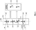
- FIG. 1 is a perspective diagram of an exemplary aircraft 100 on a runway 102 during a V1 cut.
- aircraft 100 moves along runway 102 with a velocity V and generally tracks along a runway centerline 106.
- Velocity V reaches V1 velocity at a point on runway 102 depicted as a solid line 108 near the bottom of runway 102 in FIG. 1 .
- Aircraft 100 experiences a V1 cut at a point on runway 102 depicted as a dashed line 104 near the bottom of runway 102. More specifically, in the exemplary example aircraft 100 experiences a port engine failure, resulting in at least some amount of yaw towards the port, or left, side of aircraft 100 as illustrated at aircraft position 110.
- Rudder actuation 112 provides corrective yaw, and results in a partially corrected track for aircraft 100, as illustrated at aircraft position 114.
- Aircraft position 114 also illustrates that initial rudder actuation 112, in certain circumstances, does not fully correct for the port yaw caused by the port engine failure. Consequently, the pilot applies additional starboard rudder, as illustrated by rudder actuation 116 to produce further corrective yaw.
- Rudder actuation 116 results in a more corrected track for aircraft 100, relative to runway centerline 106, as illustrated by aircraft position 118.
- VR velocity is defined as the velocity of aircraft 100 at which the pilot should pitch aircraft 100 up for takeoff.
- FIG. 1 illustrates this process using discrete aircraft positions 110, 114, and 118, and discrete rudder actuations 112 and 116, by way of example.
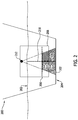
- FIG. 2 is an illustration of an exemplary pilot field-of-view 200 from aircraft 100 during a V1 cut.
- Field-of-view 200 includes a horizon 202, and at least a portion of runway 102 and runway centerline 106 (shown in FIG. 1 ).
- Runway 102 enters pilot field-of-view 200 just above a glare shield boundary 204, and runway 102 extends to an edge 206, within field-of-view 200.
- Runway 102 and runway centerline 106 in field-of-view 200 illustrate the runway visual range (RVR) for the pilot during takeoff.
- RVR runway visual range
- Field-of-view 200 includes a pilot display 208.
- Pilot display 208 is depicted as a heads-up-display (HUD).
- pilot display 208 may be any other suitable pilot display, including, for example, and without limitation, an LED display, an LCD, a projection display, visor display, or any other suitable pilot mountable or aircraft mountable displays.
- Pilot display 208 displays a runway centerline indicator 210 that virtually extends the pilot's RVR during a V1 cut, as if to extend runway 102 out to a pilot focal point 212.
- Runway centerline indicator 210 is displayed according to a plurality of runway centerline positions 214 that define runway centerline 106.
- FIG. 3 is a cross-sectional diagram of pilot field-of-view 200 from aircraft 100 during a V1 cut.
- Field-of-view 200 is further illustrated by a pilot 310 and pilot focal point 212 (shown in FIG. 2 ).
- Field-of-view 200 is bounded by glare shield 204 (shown in FIG. 2 ) and pilot visuals through a windshield 320 for aircraft 100.
- FIG. 3 also illustrates positioning of pilot display 208 relative to pilot 310 and windshield 320.
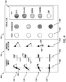
- FIG. 4 is a table of exemplary rudder inputs 400, rudder actuations 402, and visual cues 404 for aircraft 100 during the V1 cut illustrated in FIG. 1 .
- FIG. 4 illustrates rudder inputs 400, rudder actuations 402, and visual cues 404 for aircraft positions 110, 114, and 118, as well as an aircraft position 406 illustrating an over-correction in yaw.
- Zero rudder input is initially illustrated for a rotary rudder input mechanism 408, and subsequently for a linear rudder input mechanism 410.
- Zero rudder input corresponds to zero rudder actuation 412.
- FIG. 4 illustrates only rudder input 400 and rudder actuation 402 from the pilot during the V1 cut.
- additional rudder input and rudder actuation may be present through other mechanisms, such as, for example, through trim.
- Visual cues 404 include colored yaw feedback indicators 414 and 416 that indicate whether port or starboard rudder is needed to correct for yaw induced by the engine failure.
- FIG. 4 includes a key 418 defining color representations for visual cues 404.
- aircraft 100 experiences port yaw, zero rudder input, and zero rudder actuation from the pilot.
- the port yaw calls for starboard rudder for correction.
- port yaw feedback indicator 414 is off, or not illuminated, and starboard yaw feedback indicator 416 is illuminated in red.
- the pilot has commanded some rudder input, illustrated by counter-clockwise movement of a rotary pedal 420 caused by rotary input mechanism 408, upward linear translation of starboard pedal 422 and downward linear translation of port pedal 424 caused by linear rudder input mechanism 410.
- the rudder input corresponds to rudder actuation 412, illustrated by a counter-clockwise rotation of a rudder 426 relative to an aircraft centerline 428.
- Rudder actuation 412 at aircraft position 114 partially corrects the port yaw induced by the V1 cut.
- Yaw feedback indicators 414 and 416 respond accordingly: port yaw feedback indicator 414 remaining off, and starboard yaw feedback indicator 416 changing from red to yellow, indicating additional rudder input is needed.
- the pilot has commanded additional rudder input, illustrated by further counter-clockwise rotation of rotary pedal 420 caused by rotary rudder input mechanism 408.
- the additional rudder input is also illustrated by further upward linear translation of starboard pedal 422 caused by linear rudder input mechanism 410 and further downward linear translation of port pedal 424 caused by linear rudder input mechanism 410.
- the rudder input corresponds to further rudder actuation 412, illustrated by further counter-clockwise rotation of rudder 426 relative to aircraft centerline 428.
- Rudder actuation 412 at aircraft position 118 fully corrects the port yaw induced by the V1 cut.
- Yaw feedback indicators 414 and 416 respond accordingly: port yaw feedback indicator 414 remaining off, and starboard yaw feedback indicator 416 changing from yellow to green, indicating no additional rudder input is needed.
- the pilot has commanded additional rudder input, illustrated by further counter-clockwise rotation of rotary pedal 420.
- the additional rudder input is also illustrated by further upward linear translation of starboard pedal 422 of linear rudder input mechanism 410 and further downward linear translation of port pedal 424 caused by linear rudder input mechanism 410.
- the rudder input corresponds to further rudder actuation 412, illustrated by further counter-clockwise rotation of rudder 426 relative to aircraft centerline 428.
- Rudder actuation 412 at aircraft position 406 over-corrects the port yaw induced by the V1 cut.
- Yaw feedback indicators 414 and 416 respond accordingly: port yaw feedback indicator 414 remaining off, and starboard yaw feedback indicator 416 changing from green to flashing green, yellow, or red, depending on the degree of over-correction. Yaw feedback indicators 414 and 416 at aircraft position 406 indicate starboard rudder input should be reduced.
- FIG. 5 is another table of exemplary rudder inputs 400, rudder actuations 402, and visual cues 500 for aircraft 100 during a V1 cut.
- FIG. 5 illustrates alternative visual cues 500 for aircraft positions 110, 114, 118, and 406, shown in FIGs. 1 and 4 .
- Visual cues 500 include a yaw feedback indicator 502 indicating yaw feedback using a dial 508 having an indicator element 504 relative to a track line 506.
- dial 508 indicates starboard rudder is needed by indicator element 504 positioned orthogonal to track line 506, and toward the starboard side of aircraft 100.
- dial 508 indicates additional starboard rudder is needed by indicator element 504 still positioned in the starboard quadrant, but nearer track line 506 as compared to indicator element 504's position at aircraft position 110.
- rudder input is illustrated for rotary rudder input mechanism 408 and for linear rudder input mechanism 410 correspond to a fully corrective rudder actuation 412.
- Dial 508 indicates full yaw correction with indicator element 504 overlapping track line 506.
- rudder input is illustrated for rotary rudder input mechanism 408 and for linear rudder input mechanism 410 correspond to over-correcting rudder actuation 412.
- Dial 508 indicates the over-correction with indicator element 504 positioned in the port quadrant relative to track line 506.
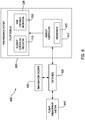
- FIG. 6 is a block diagram of an exemplary pilot display system 600 for aircraft 100 (shown in FIG. 1 ).
- Pilot display system 600 includes a yaw feedback system 605.
- Yaw feedback system 605 includes pilot display 208 (shown in FIGs. 2 and 3 ) and a display controller 610.
- Display controller 610 includes a processor 615 and is coupled to a data bus 620.
- Data bus 620 includes any suitable aircraft communication link, such as, for example, an ARINC-429 bus.
- the ARINC-429 bus is a standardized two wire differential bus that communicatively couples a transmitter to one or more receivers.
- Data bus 620 communicatively couples display controller 610 to various aircraft systems, such as, for example, a navigation system 630 and a flight management system 640.
- processor 615 determines a yaw difference between a current track of aircraft 100 and runway centerline 106 (shown in FIGs. 1 and 2 ).
- Display controller 610 controls pilot display 208 to display runway centerline indicator 210, virtually extending RVR for the pilot.
- Display controller 610 further controls, using the processor, pilot display 208 to display a yaw feedback indicator 650, such as port and starboard yaw feedback indicators 414 and 416 or dial 508 (shown in FIGs. 4 and 5 ).
- Yaw feedback indicator 650 is operable to prompt the pilot for yaw input to compensate for the determined yaw difference between the current track and runway centerline 106.
- yaw feedback indicator 650 includes indicator lights that illuminate in a plurality of colors, such as, for example, port and starboard yaw feedback indicators 414 and 416, otherwise referred to as port indicator light 414 and starboard indicator light 416.
- Display controller 610 selects which of the plurality of colors to illuminate based on an estimated magnitude of yaw input necessary to compensate for the yaw difference determined based on the current track of aircraft 100 and runway centerline 106.
- Display controller 610 illuminates port indicator light 414 when prompting for port yaw input, and illuminates starboard indicator light 416 when prompting starboard yaw input.
- yaw feedback indicator 650 includes dial 508 that defines a range of rudder input over which indicator element 504 operates. Indicator element 504 moves relative to track line 506 based on the determined yaw difference.
- flight management system 640 includes a processor configured to determine the yaw difference between the current track of aircraft 100 and runway centerline 106. Flight management system 640 communicates with display controller 610 over data bus 620 to control display of runway centerline indicator 210 and yaw feedback indicator 650. Flight management system 640 is further configured to compute a yaw input necessary to compensate for the determine yaw difference based on an airspeed of aircraft 100.
- display controller 610 receives plurality of runway centerline positions 214, which define runway centerline 106. Display controller 610 also receives the yaw difference between the current track of aircraft 100 and runway centerline 106. Display controller 610 then controls pilot display 208 to display runway centerline indicator 210 according to plurality of centerline positions 214, and to display yaw feedback indicator 650 to prompt the pilot for yaw input to compensate for the determined yaw difference. In such an example, display controller 610 receives plurality of runway centerline positions 214 and the yaw difference over data bus 620. In certain examples, flight management system 640 computes the yaw difference based on plurality of runway centerline positions 214 and the current track. In certain examples, navigation system 630 is configured to store plurality of runway centerline positions 214 and transmit those positions to display controller 610 over data bus 620 for display on pilot display 208. In certain examples, pilot display 208 includes a HUD for aircraft 100.
- FIG. 7 is a flow diagram of an exemplary method 700 of prompting a pilot of aircraft 100 during takeoff using pilot display system 600 (shown in FIG. 6 ), for example.
- Method 700 is initiated 710 and the processor of display controller 610 receives 720 plurality of runway centerline positions 214 that define runway centerline 106.
- the processor computes 730 a yaw difference between a current track of aircraft 100 and runway centerline 106.
- the current track of aircraft 100 is received over data bus 620 from flight management system 640.
- display controller 610 receives the determined yaw difference over data bus 620.
- the yaw difference is computed by another processor located in flight management system 640, for example.
- Runway centerline indicator 210 is displayed 740 on pilot display 208 to virtually extend the RVR for the pilot of aircraft 100.
- Pilot display 208 is further configured to display 750 yaw feedback indicator 650 to prompt the pilot for yaw input to compensate for the yaw difference.
- method 700 includes extrapolating, by the processor of display controller 610, plurality of runway centerline positions 214 to render runway centerline indicator 210 on pilot display 208.
- method 700 also includes computing, by the processor, a yaw input necessary to compensate for the determined yaw difference. Such computing includes selecting port yaw input when the yaw difference indicates a current starboard yaw and selecting a starboard yaw input when the yaw difference indicates a current port yaw.
- Such computing also includes computing a magnitude of yaw input based on the airspeed of aircraft 100, for example. The computed magnitude of yaw input, in certain examples, may be incorporated into yaw feedback indicator 650. The method terminates at an end step 760.
- the above described examples of yaw feedback systems for use by aircraft during takeoff provide pilots visual indicators of yaw in the event of a V1 cut. More specifically, the present disclosure describes a runway centerline indicator that virtually extends runway visual range (RVR) for the pilot, giving the pilot sufficient visual depth-of-field to apply appropriate yaw compensation during the V1 cut. The present disclosure further describes a yaw feedback indicator that prompts the pilot for an appropriate yaw input to compensate for yaw induced by the V1 cut. Such yaw feedback indicators may include dials, indicator lights, or a combination of both, for example.
- the yaw feedback systems described herein utilize data from a navigation system to ascertain the position of the runway centerline.
- the yaw feedback systems described herein further utilize data from a flight management system to compute the appropriate yaw compensation.
- the yaw feedback systems may be implemented, for example, within a HUD system for the aircraft.
- Exemplary examples of methods, systems, and apparatus for yaw feedback systems are not limited to the specific examples described herein, but rather, components of systems and/or steps of the methods may be utilized independently and separately from other components and/or steps described herein.
- the methods may also be used in combination with other non-conventional yaw feedback systems, and are not limited to practice with only the systems and methods as described herein. Rather, the exemplary example can be implemented and utilized in connection with many other applications, equipment, and systems that may benefit from increased efficiency, reduced operational cost, and reduced capital expenditure.
Landscapes
- Engineering & Computer Science (AREA)
- Aviation & Aerospace Engineering (AREA)
- Physics & Mathematics (AREA)
- General Physics & Mathematics (AREA)
- Automation & Control Theory (AREA)
- Radar, Positioning & Navigation (AREA)
- Remote Sensing (AREA)
- Traffic Control Systems (AREA)
Abstract
Description
- The field of the disclosure relates generally to pilot displays for aircraft and, more specifically, to a pilot display for use during takeoff maneuvers.
- Most fixed wing aircraft have well-established performance targets, thresholds, limits, and procedures for various maneuvers. Each aircraft has several defined velocity thresholds during takeoff that guide pilots in making decisions and carrying out maneuvers. These velocity thresholds include a V1 velocity value, above which a takeoff cannot be abandoned without significant danger to the aircraft, crew, and passengers. The V1 value, sometimes referred to as a go/no go value, is defined for a particular aircraft such that risk in continuing with takeoff and flight is lower than risk to the aircraft, crew, and passengers in aborting the takeoff above V1. The V1 value is followed by a VR velocity value at which the aircraft should rotate, i.e., pitch up, to take off.
- The time elapsed between the V1 and VR values is often brief, but long enough for a number of failures to occur, under which the pilot will continue the takeoff and flight. One such failure is an engine failure. When a side engine fails between the V1 and VR values, referred to as a V1 cut, the aircraft experiences a loss of port or starboard power and a subsequent corresponding yaw towards the side of the aircraft with the failed engine. Takeoff procedures call for immediate correction before rotation to ensure stable flight after rotation. Such corrections include, among other actions, a yaw correction using the aircraft's rudder to achieve a proper track before rotation. Certain aircraft utilize automated flight control systems to carry out the V1 cut maneuver, while others rely on pilots and their training. A successful V1 cut maneuver is challenging for pilots, particularly in aircraft with limited visuals and attenuated "feel."
- According to one aspect of the present disclosure, a yaw feedback system for use by an aircraft is provided. The yaw feedback system includes a processor, a runway centerline indicator, and a yaw feedback indicator. The processor is configured to determine a yaw difference between a current track of the aircraft and a runway centerline. The runway centerline indicator is configured to virtually extend a runway visual range (RVR) for a pilot of the aircraft. The yaw feedback indicator is coupled to the processor and configured to prompt the pilot for yaw input to compensate for the yaw difference.
- According to another aspect of the present disclosure, a method of prompting a pilot of an aircraft during takeoff is provided. The method includes receiving, by a processor, a plurality of runway centerline positions defining a runway centerline. The method further includes computing, by the processor, a yaw difference between a current track of the aircraft and the runway centerline. The method further includes displaying a runway centerline indicator to virtually extend a runway visual range (RVR) for the pilot. The method further includes displaying a yaw feedback indicator to prompt the pilot for yaw input to compensate for the yaw difference.
- According to yet another aspect of the present disclosure, a pilot display system for an aircraft is provided. The pilot display system includes a display controller and a pilot display. The display controller is configured to receive a plurality of runway centerline positions defining a runway centerline. The display controller is further configured to receive a yaw difference between a current track of the aircraft and the runway centerline. The pilot display is coupled to the display controller. The pilot display includes a runway centerline indicator displayed according to the plurality of centerline positions. The pilot display further includes a yaw feedback indicator configured to prompt a pilot of the aircraft for yaw input to compensate for the yaw difference.
- The features, functions, and advantages that have been discussed can be achieved independently in various examples or may be combined in yet other examples further details of which can be seen with reference to the following description and drawings.
-
-
FIG. 1 is a perspective diagram of an exemplary aircraft on a runway during a V1 cut; -
FIG. 2 is an illustration of an exemplary pilot field-of-view from an aircraft during a V1 cut; -
FIG. 3 is a cross-sectional diagram of an exemplary pilot field-of-view from an aircraft during a V1 cut; -
FIG. 4 is a table of rudder commands, rudder actuations, and visual cues for an aircraft during a V1 cut; -
FIG. 5 is another table of rudder commands, rudder actuations, and visual cues for an aircraft during a V1 cut; -
FIG. 6 is a block diagram of an exemplary pilot display system; and -
FIG. 7 is a flow diagram of an exemplary method of prompting a pilot of an aircraft during takeoff. - As used herein, an element or step recited in the singular and proceeded with the word "a" or "an" should be understood as not excluding plural elements or steps unless such exclusion is explicitly recited. Furthermore, references to "one example" of the present invention or the "exemplary example" are not intended to be interpreted as excluding the existence of additional examples that also incorporate the recited features.
-
FIG. 1 is a perspective diagram of anexemplary aircraft 100 on arunway 102 during a V1 cut. During takeoff,aircraft 100 moves alongrunway 102 with a velocity V and generally tracks along arunway centerline 106. Velocity V reaches V1 velocity at a point onrunway 102 depicted as asolid line 108 near the bottom ofrunway 102 inFIG. 1 .Aircraft 100 experiences a V1 cut at a point onrunway 102 depicted as adashed line 104 near the bottom ofrunway 102. More specifically, in theexemplary example aircraft 100 experiences a port engine failure, resulting in at least some amount of yaw towards the port, or left, side ofaircraft 100 as illustrated ataircraft position 110. - In response to the yaw induced by the port engine failure, the pilot applies starboard rudder, as illustrated by
rudder actuation 112.Rudder actuation 112 provides corrective yaw, and results in a partially corrected track foraircraft 100, as illustrated ataircraft position 114.Aircraft position 114 also illustrates thatinitial rudder actuation 112, in certain circumstances, does not fully correct for the port yaw caused by the port engine failure. Consequently, the pilot applies additional starboard rudder, as illustrated byrudder actuation 116 to produce further corrective yaw. Rudderactuation 116 results in a more corrected track foraircraft 100, relative torunway centerline 106, as illustrated byaircraft position 118. - Generally, during a V1 cut, the pilot continuously applies rudder and receives visual feedback as to
aircraft 100's track, ultimately in an effort to stabilizeaircraft 100's track prior to rotation, at VR velocity, illustrated bysolid line 120 near the top ofrunway 102. VR velocity is defined as the velocity ofaircraft 100 at which the pilot should pitchaircraft 100 up for takeoff.FIG. 1 illustrates this process usingdiscrete aircraft positions discrete rudder actuations -
FIG. 2 is an illustration of an exemplary pilot field-of-view 200 fromaircraft 100 during a V1 cut. Field-of-view 200 includes ahorizon 202, and at least a portion ofrunway 102 and runway centerline 106 (shown inFIG. 1 ). Runway 102 enters pilot field-of-view 200 just above aglare shield boundary 204, andrunway 102 extends to anedge 206, within field-of-view 200. Runway 102 andrunway centerline 106 in field-of-view 200 illustrate the runway visual range (RVR) for the pilot during takeoff. - Field-of-
view 200 includes apilot display 208.Pilot display 208 is depicted as a heads-up-display (HUD). In alternative examples,pilot display 208 may be any other suitable pilot display, including, for example, and without limitation, an LED display, an LCD, a projection display, visor display, or any other suitable pilot mountable or aircraft mountable displays.Pilot display 208 displays arunway centerline indicator 210 that virtually extends the pilot's RVR during a V1 cut, as if to extendrunway 102 out to a pilotfocal point 212.Runway centerline indicator 210 is displayed according to a plurality of runway centerline positions 214 that definerunway centerline 106. -
FIG. 3 is a cross-sectional diagram of pilot field-of-view 200 fromaircraft 100 during a V1 cut. Field-of-view 200 is further illustrated by apilot 310 and pilot focal point 212 (shown inFIG. 2 ). Field-of-view 200 is bounded by glare shield 204 (shown inFIG. 2 ) and pilot visuals through awindshield 320 foraircraft 100.FIG. 3 also illustrates positioning ofpilot display 208 relative to pilot 310 andwindshield 320. -
FIG. 4 is a table ofexemplary rudder inputs 400,rudder actuations 402, andvisual cues 404 foraircraft 100 during the V1 cut illustrated inFIG. 1 .FIG. 4 illustratesrudder inputs 400,rudder actuations 402, andvisual cues 404 foraircraft positions aircraft position 406 illustrating an over-correction in yaw. - At
aircraft position 110, the port engine failure has occurred andaircraft 100 experiences port yaw before the pilot responds. The pilot provides zero rudder input. Zero rudder input is initially illustrated for a rotaryrudder input mechanism 408, and subsequently for a linearrudder input mechanism 410. Zero rudder input corresponds to zerorudder actuation 412.FIG. 4 illustratesonly rudder input 400 andrudder actuation 402 from the pilot during the V1 cut. During takeoff and flight, additional rudder input and rudder actuation may be present through other mechanisms, such as, for example, through trim. -
Visual cues 404 include coloredyaw feedback indicators FIG. 4 includes a key 418 defining color representations forvisual cues 404. Ataircraft position 110,aircraft 100 experiences port yaw, zero rudder input, and zero rudder actuation from the pilot. The port yaw calls for starboard rudder for correction. Ataircraft position 110, portyaw feedback indicator 414 is off, or not illuminated, and starboardyaw feedback indicator 416 is illuminated in red. - At
aircraft position 114, the pilot has commanded some rudder input, illustrated by counter-clockwise movement of arotary pedal 420 caused byrotary input mechanism 408, upward linear translation ofstarboard pedal 422 and downward linear translation ofport pedal 424 caused by linearrudder input mechanism 410. Ataircraft position 114, the rudder input corresponds torudder actuation 412, illustrated by a counter-clockwise rotation of arudder 426 relative to anaircraft centerline 428. Rudder actuation 412 ataircraft position 114 partially corrects the port yaw induced by the V1 cut. Yawfeedback indicators yaw feedback indicator 414 remaining off, and starboardyaw feedback indicator 416 changing from red to yellow, indicating additional rudder input is needed. - At
aircraft position 118, the pilot has commanded additional rudder input, illustrated by further counter-clockwise rotation ofrotary pedal 420 caused by rotaryrudder input mechanism 408. The additional rudder input is also illustrated by further upward linear translation ofstarboard pedal 422 caused by linearrudder input mechanism 410 and further downward linear translation ofport pedal 424 caused by linearrudder input mechanism 410. Ataircraft position 118, the rudder input corresponds to furtherrudder actuation 412, illustrated by further counter-clockwise rotation ofrudder 426 relative toaircraft centerline 428. Rudder actuation 412 ataircraft position 118 fully corrects the port yaw induced by the V1 cut. Yawfeedback indicators yaw feedback indicator 414 remaining off, and starboardyaw feedback indicator 416 changing from yellow to green, indicating no additional rudder input is needed. - At
aircraft position 406, the pilot has commanded additional rudder input, illustrated by further counter-clockwise rotation ofrotary pedal 420. The additional rudder input is also illustrated by further upward linear translation ofstarboard pedal 422 of linearrudder input mechanism 410 and further downward linear translation ofport pedal 424 caused by linearrudder input mechanism 410. Ataircraft position 406, the rudder input corresponds to furtherrudder actuation 412, illustrated by further counter-clockwise rotation ofrudder 426 relative toaircraft centerline 428. Rudder actuation 412 ataircraft position 406 over-corrects the port yaw induced by the V1 cut. Yawfeedback indicators yaw feedback indicator 414 remaining off, and starboardyaw feedback indicator 416 changing from green to flashing green, yellow, or red, depending on the degree of over-correction. Yawfeedback indicators aircraft position 406 indicate starboard rudder input should be reduced. -
FIG. 5 is another table ofexemplary rudder inputs 400,rudder actuations 402, andvisual cues 500 foraircraft 100 during a V1 cut.FIG. 5 illustrates alternativevisual cues 500 foraircraft positions FIGs. 1 and4 .Visual cues 500 include ayaw feedback indicator 502 indicating yaw feedback using adial 508 having anindicator element 504 relative to atrack line 506. - At
aircraft position 110, whereaircraft 100 experiences port yaw induced by the V1 cut, zero rudder input is illustrated for rotaryrudder input mechanism 408 and for linearrudder input mechanism 410 from the pilot, and zerorudder actuation 412, dial 508 indicates starboard rudder is needed byindicator element 504 positioned orthogonal to trackline 506, and toward the starboard side ofaircraft 100. - Likewise, at
aircraft position 114, where rudder input is illustrated for rotaryrudder input mechanism 408 and for linearrudder input mechanism 410 correspond to somestarboard rudder actuation 412, dial 508 indicates additional starboard rudder is needed byindicator element 504 still positioned in the starboard quadrant, butnearer track line 506 as compared toindicator element 504's position ataircraft position 110. - At
aircraft position 118, rudder input is illustrated for rotaryrudder input mechanism 408 and for linearrudder input mechanism 410 correspond to a fullycorrective rudder actuation 412.Dial 508 indicates full yaw correction withindicator element 504 overlappingtrack line 506. - At
aircraft position 406, rudder input is illustrated for rotaryrudder input mechanism 408 and for linearrudder input mechanism 410 correspond toover-correcting rudder actuation 412.Dial 508 indicates the over-correction withindicator element 504 positioned in the port quadrant relative to trackline 506. -
FIG. 6 is a block diagram of an exemplarypilot display system 600 for aircraft 100 (shown inFIG. 1 ).Pilot display system 600 includes ayaw feedback system 605. Yawfeedback system 605 includes pilot display 208 (shown inFIGs. 2 and3 ) and adisplay controller 610.Display controller 610 includes aprocessor 615 and is coupled to adata bus 620.Data bus 620 includes any suitable aircraft communication link, such as, for example, an ARINC-429 bus. The ARINC-429 bus is a standardized two wire differential bus that communicatively couples a transmitter to one or more receivers.Data bus 620 communicatively couples displaycontroller 610 to various aircraft systems, such as, for example, anavigation system 630 and aflight management system 640. - In certain examples,
processor 615 determines a yaw difference between a current track ofaircraft 100 and runway centerline 106 (shown inFIGs. 1 and2 ).Display controller 610controls pilot display 208 to displayrunway centerline indicator 210, virtually extending RVR for the pilot.Display controller 610 further controls, using the processor,pilot display 208 to display ayaw feedback indicator 650, such as port and starboard yawfeedback indicators FIGs. 4 and5 ). Yawfeedback indicator 650 is operable to prompt the pilot for yaw input to compensate for the determined yaw difference between the current track andrunway centerline 106. - In one example,
yaw feedback indicator 650 includes indicator lights that illuminate in a plurality of colors, such as, for example, port and starboard yawfeedback indicators port indicator light 414 andstarboard indicator light 416.Display controller 610 selects which of the plurality of colors to illuminate based on an estimated magnitude of yaw input necessary to compensate for the yaw difference determined based on the current track ofaircraft 100 andrunway centerline 106.Display controller 610 illuminates port indicator light 414 when prompting for port yaw input, and illuminates starboard indicator light 416 when prompting starboard yaw input. - In another example,
yaw feedback indicator 650 includes dial 508 that defines a range of rudder input over whichindicator element 504 operates.Indicator element 504 moves relative to trackline 506 based on the determined yaw difference. - In certain examples,
flight management system 640 includes a processor configured to determine the yaw difference between the current track ofaircraft 100 andrunway centerline 106.Flight management system 640 communicates withdisplay controller 610 overdata bus 620 to control display ofrunway centerline indicator 210 andyaw feedback indicator 650.Flight management system 640 is further configured to compute a yaw input necessary to compensate for the determine yaw difference based on an airspeed ofaircraft 100. - In one example,
display controller 610 receives plurality of runway centerline positions 214, which definerunway centerline 106.Display controller 610 also receives the yaw difference between the current track ofaircraft 100 andrunway centerline 106.Display controller 610 then controlspilot display 208 to displayrunway centerline indicator 210 according to plurality ofcenterline positions 214, and to displayyaw feedback indicator 650 to prompt the pilot for yaw input to compensate for the determined yaw difference. In such an example,display controller 610 receives plurality of runway centerline positions 214 and the yaw difference overdata bus 620. In certain examples,flight management system 640 computes the yaw difference based on plurality of runway centerline positions 214 and the current track. In certain examples,navigation system 630 is configured to store plurality of runway centerline positions 214 and transmit those positions to displaycontroller 610 overdata bus 620 for display onpilot display 208. In certain examples,pilot display 208 includes a HUD foraircraft 100. -
FIG. 7 is a flow diagram of anexemplary method 700 of prompting a pilot ofaircraft 100 during takeoff using pilot display system 600 (shown inFIG. 6 ), for example.Method 700 is initiated 710 and the processor ofdisplay controller 610 receives 720 plurality of runway centerline positions 214 that definerunway centerline 106. The processor computes 730 a yaw difference between a current track ofaircraft 100 andrunway centerline 106. In certain examples, the current track ofaircraft 100 is received overdata bus 620 fromflight management system 640. In alternative examples,display controller 610 receives the determined yaw difference overdata bus 620. In such examples, the yaw difference is computed by another processor located inflight management system 640, for example. -
Runway centerline indicator 210 is displayed 740 onpilot display 208 to virtually extend the RVR for the pilot ofaircraft 100.Pilot display 208 is further configured to display 750yaw feedback indicator 650 to prompt the pilot for yaw input to compensate for the yaw difference. - In certain examples,
method 700 includes extrapolating, by the processor ofdisplay controller 610, plurality of runway centerline positions 214 to renderrunway centerline indicator 210 onpilot display 208. In certain examples,method 700 also includes computing, by the processor, a yaw input necessary to compensate for the determined yaw difference. Such computing includes selecting port yaw input when the yaw difference indicates a current starboard yaw and selecting a starboard yaw input when the yaw difference indicates a current port yaw. Such computing also includes computing a magnitude of yaw input based on the airspeed ofaircraft 100, for example. The computed magnitude of yaw input, in certain examples, may be incorporated intoyaw feedback indicator 650. The method terminates at anend step 760. - The above described examples of yaw feedback systems for use by aircraft during takeoff provide pilots visual indicators of yaw in the event of a V1 cut. More specifically, the present disclosure describes a runway centerline indicator that virtually extends runway visual range (RVR) for the pilot, giving the pilot sufficient visual depth-of-field to apply appropriate yaw compensation during the V1 cut. The present disclosure further describes a yaw feedback indicator that prompts the pilot for an appropriate yaw input to compensate for yaw induced by the V1 cut. Such yaw feedback indicators may include dials, indicator lights, or a combination of both, for example. The yaw feedback systems described herein utilize data from a navigation system to ascertain the position of the runway centerline. The yaw feedback systems described herein further utilize data from a flight management system to compute the appropriate yaw compensation. The yaw feedback systems may be implemented, for example, within a HUD system for the aircraft.
- Exemplary examples of methods, systems, and apparatus for yaw feedback systems are not limited to the specific examples described herein, but rather, components of systems and/or steps of the methods may be utilized independently and separately from other components and/or steps described herein. For example, the methods may also be used in combination with other non-conventional yaw feedback systems, and are not limited to practice with only the systems and methods as described herein. Rather, the exemplary example can be implemented and utilized in connection with many other applications, equipment, and systems that may benefit from increased efficiency, reduced operational cost, and reduced capital expenditure.
- Further, the disclosure comprises examples according to the following clauses
- Clause 1. A yaw feedback system (605) for use by a pilot of an aircraft (100) during takeoff, comprising:
- a processor (615) configured to determine a yaw difference between a current track of the aircraft and a runway centerline (106);
- a runway centerline indicator (210) configured to virtually extend a runway visual range "RVR" for a pilot of the aircraft; and
- a yaw feedback indicator (650) coupled to the processor and configured to prompt the pilot for a yaw input to compensate for the yaw difference.
- Clause 2. The yaw feedback system (605) of Clause 1, wherein the yaw feedback indicator (650) comprises an indicator light (414,416) operable to illuminate in a plurality of colors, wherein an illuminated color of the indicator light is selected based on an estimated magnitude of yaw input necessary to compensate for the yaw difference.
- Clause 3. The yaw feedback system (605) of Clause 1, wherein the yaw feedback indicator (650) comprises a port indicator light (414) and a starboard indicator light (416), the port indicator light configured to illuminate when prompting the pilot for port yaw input, the starboard indicator light configured to illuminate when prompting the pilot for starboard yaw input.
- Clause 4. The yaw feedback system (605) of Clause 1, wherein the yaw feedback indicator (650) comprises a dial (508) defining a range of rudder input over which an indicator element (504) operates, the dial configured to move the indicator element based on the yaw difference.
- Clause 5. The yaw feedback system (605) of Clause 1, wherein the processor (615) is located within a display controller (610) for a pilot display (208) on which the runway centerline indicator (210) and the yaw feedback indicator (650) are displayed.
- Clause 6. The yaw feedback system (605) of Clause 1, wherein the processor (615) is located within a flight management system (640) coupled to the runway centerline indicator (210) and the yaw feedback indicator (650) through a data bus (620).
- Clause 7. The yaw feedback system (605) of Clause 1, wherein the processor (615) is further configured to compute a yaw input necessary to compensate for the yaw difference based at least on an airspeed of the aircraft (100).
- Clause 8. A method (700) of prompting a pilot of an aircraft (100) during takeoff, the method comprising:
- receiving (720), by a processor (615), a plurality of runway centerline positions (214) defining a runway centerline (106);
- computing (730), by the processor, a yaw difference between a current track of the aircraft and the runway centerline;
- displaying (740) a runway centerline indicator (210) to virtually extend a runway visual range "RVR" for the pilot; and
- displaying (750) a yaw feedback indicator (650) to prompt the pilot for a yaw input to compensate for the yaw difference.
- Clause 9. The method (700) of Clause 8 further comprising extrapolating, by the processor (615), the plurality of runway centerline positions (214) to render the runway centerline indicator (210) on a pilot display (208).
- Clause 10. The method (700) of Clause 8 further comprising receiving, by the processor (615), the current track of the aircraft from a flight management system (640).
- Clause 11. The method (700) of Clause 8 further comprising computing, by the processor (615), a yaw input necessary to compensate for the yaw difference.
- Clause 12. The method (700) of Clause 11, wherein computing the yaw input comprises:
- selecting port yaw input when the yaw difference indicates a current starboard yaw; and
- selecting starboard yaw input when the yaw difference indicates a current port yaw.
- Clause 13. The method (700) of Clause 11, wherein computing the yaw input comprises computing a magnitude of yaw input based at least on an airspeed of the aircraft (100).
-
Clause 14. The method (700) of Clause 13, wherein the yaw feedback indicator (650) includes a numeric indicator of the magnitude of yaw input. - Clause 15. A pilot display system (600) for an aircraft (100), the pilot display system comprising:
- a display controller (610) configured to:
- receive (720) a plurality of runway centerline positions (214) defining a runway centerline (106), and
- compute (730) a yaw difference between a current track of the aircraft and the runway centerline; and
- a pilot display (208) coupled to the display controller, the pilot display comprising:
- a runway centerline indicator (210) displayed according to the plurality of centerline positions, and
- a yaw feedback indicator (650) configured to prompt a pilot of the aircraft for a yaw input to compensate for the yaw difference.
- a display controller (610) configured to:
- Clause 16. The pilot display system (600) of Clause 15 further comprising a data bus (620) coupled to the display controller (610) and configured to deliver the runway centerline positions (214) and the yaw difference to the display controller.
- Clause 17. The pilot display system (600) of Clause 16 further comprising a flight management system (640) coupled to the data bus (620) and configured to compute the yaw difference based on the plurality of runway centerline positions (214) and the current track.
- Clause 18. The pilot display system (600) of Clause 16, wherein the data bus (620) is further coupled to a navigation system (630) configured to store the runway centerline positions (214).
- Clause 19. The pilot display system (600) of Clause 15, wherein the pilot display (208) comprises a heads-up-display "HUD" for the aircraft (100).
- Clause 20. The pilot display system (600) of Clause 15, wherein the yaw feedback indicator (650) comprises a dial (508) defining a range of rudder input over which an indicator element (504) operates, the dial configured to move the indicator element based on the yaw difference.
- This written description uses examples to disclose various examples, which include the best mode, to enable any person skilled in the art to practice those examples, including making and using any devices or systems and performing any incorporated methods. The patentable scope is defined by the claims, and may include other examples that occur to those skilled in the art. Such other examples are intended to be within the scope of the claims if they have structural elements that do not differ from the literal language of the claims, or if they include equivalent structural elements with insubstantial differences from the literal languages of the claims.
Claims (15)
- A yaw feedback system (605) for use by a pilot of an aircraft (100) during takeoff, comprising:a processor (615) configured to determine a yaw difference between a current track of the aircraft and a runway centerline (106);a runway centerline indicator (210) configured to virtually extend a runway visual range "RVR" for a pilot of the aircraft (100); anda yaw feedback indicator (650) coupled to the processor (615) and configured to prompt the pilot for a yaw input to compensate for the yaw difference.
- The yaw feedback system (605) of Claim 1, wherein the yaw feedback indicator (650) comprises an indicator light (414,416) operable to illuminate in a plurality of colors, wherein an illuminated color of the indicator light (414, 416) is selected based on an estimated magnitude of yaw input necessary to compensate for the yaw difference.
- The yaw feedback system (605) of Claim 1, wherein the yaw feedback indicator (650) comprises a port indicator light (414) and a starboard indicator light (416), the port indicator light (414) configured to illuminate when prompting the pilot for port yaw input, the starboard indicator light (416) configured to illuminate when prompting the pilot for starboard yaw input.
- The yaw feedback system (605) of Claim 1, wherein the yaw feedback indicator (650) comprises a dial (508) defining a range of rudder input over which an indicator element (504) operates, the dial (508) configured to move the indicator element (504) based on the yaw difference.
- The yaw feedback system (605) of any one of Claims 1-4, wherein the processor (615) is further configured to compute a yaw input necessary to compensate for the yaw difference based at least on an airspeed of the aircraft (100).
- A method (700) of prompting a pilot of an aircraft (100) during takeoff, the method comprising:receiving (720), by a processor (615), a plurality of runway centerline positions (214) defining a runway centerline (106);computing (730), by the processor, a yaw difference between a current track of the aircraft and the runway centerline;displaying (740) a runway centerline indicator (210) to virtually extend a runway visual range "RVR" for the pilot; anddisplaying (750) a yaw feedback indicator (650) to prompt the pilot for a yaw input to compensate for the yaw difference.
- The method (700) of Claim 6 further comprising extrapolating, by the processor (615), the plurality of runway centerline positions (214) to render the runway centerline indicator (210) on a pilot display (208).
- The method (700) of Claim 6 or 7 further comprising receiving, by the processor (615), the current track of the aircraft (100) from a flight management system (640).
- The method (700) of any one of Claims 6-8 further comprising computing, by the processor (615), a yaw input necessary to compensate for the yaw difference.
- The method (700) of Claim 9, wherein computing the yaw input comprises:selecting port yaw input when the yaw difference indicates a current starboard yaw; andselecting starboard yaw input when the yaw difference indicates a current port yaw.
- The method (700) of Claim 9, wherein computing the yaw input comprises computing a magnitude of yaw input based at least on an airspeed of the aircraft (100).
- A pilot display system (600) for an aircraft (100), the pilot display system (600) comprising:a display controller (610) configured to:receive (720) a plurality of runway centerline positions (214) defining a runway centerline (106), andcompute (730) a yaw difference between a current track of the aircraft (100) and the runway centerline; anda pilot display (208) coupled to the display controller, the pilot display (208) comprising:a runway centerline indicator (210) displayed according to the plurality of centerline positions, anda yaw feedback indicator (650) configured to prompt a pilot of the aircraft for a yaw input to compensate for the yaw difference.
- The pilot display system (600) of Claim 12 further comprising a data bus (620) coupled to the display controller (610) and configured to deliver the runway centerline positions (214) and the yaw difference to the display controller.
- The pilot display system (600) of Claim 13 further comprising a flight management system (640) coupled to the data bus (620) and configured to compute the yaw difference based on the plurality of runway centerline positions (214) and the current track.
- The pilot display system (600) of any one of Claims 12-14, wherein the yaw feedback indicator (650) comprises a dial (508) defining a range of rudder input over which an indicator element (504) operates, the dial (508) configured to move the indicator element (504) based on the yaw difference.
Applications Claiming Priority (1)
| Application Number | Priority Date | Filing Date | Title |
|---|---|---|---|
| US15/252,994 US10399696B2 (en) | 2016-08-31 | 2016-08-31 | Aircraft pilot display system and method of use |
Publications (2)
| Publication Number | Publication Date |
|---|---|
| EP3290868A1 true EP3290868A1 (en) | 2018-03-07 |
| EP3290868B1 EP3290868B1 (en) | 2021-05-05 |
Family
ID=59215592
Family Applications (1)
| Application Number | Title | Priority Date | Filing Date |
|---|---|---|---|
| EP17177594.3A Active EP3290868B1 (en) | 2016-08-31 | 2017-06-23 | Aircraft pilot display system and method of use |
Country Status (3)
| Country | Link |
|---|---|
| US (1) | US10399696B2 (en) |
| EP (1) | EP3290868B1 (en) |
| CN (1) | CN107776903B (en) |
Families Citing this family (2)
| Publication number | Priority date | Publication date | Assignee | Title |
|---|---|---|---|---|
| US20190283862A1 (en) * | 2018-03-16 | 2019-09-19 | Honeywell International Inc. | Flight control system |
| US11364992B2 (en) * | 2018-10-23 | 2022-06-21 | The Boeing Company | Aligning aircraft with runway centerline during takeoff |
Citations (2)
| Publication number | Priority date | Publication date | Assignee | Title |
|---|---|---|---|---|
| EP2600330A1 (en) * | 2011-11-30 | 2013-06-05 | Honeywell International Inc. | System and method for aligning aircraft and runway headings during takeoff roll |
| US8560149B1 (en) * | 2012-09-20 | 2013-10-15 | Honeywell International Inc. | Systems and methods for takeoff assistance and analysis |
Family Cites Families (29)
| Publication number | Priority date | Publication date | Assignee | Title |
|---|---|---|---|---|
| US3574283A (en) * | 1967-12-27 | 1971-04-13 | William R Albers | A numeric collimated display including means for projecting elevation, attitude and speed information |
| US3837603A (en) * | 1973-01-04 | 1974-09-24 | Collins Radio Co | Lateral axis rollout, go-around, takeoff control for aircraft |
| US4006632A (en) * | 1975-11-04 | 1977-02-08 | Aeritalia S.P.A. | Aircraft turn coordinator |
| US4172632A (en) * | 1976-01-21 | 1979-10-30 | Holmes Lawrence Jr | Method and apparatus producing three-dimensional shadow images |
| US4330212A (en) * | 1978-12-18 | 1982-05-18 | Grumman Aerospace Corporation | Triaxis laser alignment system and method |
| US4313726A (en) * | 1979-06-29 | 1982-02-02 | The United States Of America As Represented By The Administrator Of National Aeronautics And Space Administration | Environmental fog/rain visual display system for aircraft simulators |
| US5008825A (en) * | 1989-05-01 | 1991-04-16 | Nadkarni Arun A | Apparatus and methods for automatically maintaining aircraft track angle |
| FR2654856B1 (en) * | 1989-11-17 | 1992-03-20 | Aerospatiale | METHOD FOR VISUALIZING THE ATTITUDE OF AN AIRCRAFT, FOR AIDING PILOTAGE IN SPACE. |
| US6121999A (en) * | 1997-06-09 | 2000-09-19 | Schaack; David F. | Eliminating routine alignment calibrations in perspective dimensional measurements |
| US6236876B1 (en) * | 1996-08-30 | 2001-05-22 | The Whitaker Corporation | Navigable probe and motor control apparatus |
| WO1998008429A1 (en) * | 1996-08-30 | 1998-03-05 | The Whitaker Corporation | Apparatus to flex a bendable probe |
| US6702229B2 (en) | 2001-08-08 | 2004-03-09 | Norman G. Anderson | Method, apparatus and article to display flight information |
| FR2854962B1 (en) * | 2003-05-14 | 2005-08-05 | Airbus France | METHOD AND DEVICE FOR CONTROLLING AN AIRCRAFT |
| US7364121B2 (en) * | 2005-03-14 | 2008-04-29 | The Boeing Company | Methods and systems for automatically controlling aircraft takeoff rolls |
| FR2909461B1 (en) | 2006-12-05 | 2014-08-22 | Airbus France | METHOD AND DEVICE FOR AUTOMATICALLY REMOVING AN AIRCRAFT. |
| US8774986B1 (en) | 2007-05-31 | 2014-07-08 | Rockwell Collins, Inc | Method, system, and apparatus for takeoff rotation guidance |
| US8392039B2 (en) * | 2008-05-29 | 2013-03-05 | Honeywell International Inc. | Method and system displaying crosswind correction for approach to a runway |
| US20110040431A1 (en) * | 2009-08-11 | 2011-02-17 | Honeywell International Inc. | Automated take off control system and method |
| US8249806B1 (en) * | 2009-08-12 | 2012-08-21 | Rockwell Collins, Inc. | System, module, and method for varying the intensity of a visual aid depicted on an aircraft display unit |
| US8800912B2 (en) * | 2009-10-09 | 2014-08-12 | Oliver Vtol, Llc | Three wing, six-tilt propulsion unit, VTOL aircraft |
| US20110282580A1 (en) * | 2010-05-11 | 2011-11-17 | Honeywell International Inc. | Method of image based navigation for precision guidance and landing |
| US9315177B2 (en) * | 2012-03-14 | 2016-04-19 | Textron Innovations Inc. | Antilock braking system with directional control |
| JP5432313B2 (en) * | 2012-03-30 | 2014-03-05 | 日信工業株式会社 | Motion stabilization device for articulated vehicles |
| US9310222B1 (en) | 2014-06-16 | 2016-04-12 | Sean Patrick Suiter | Flight assistant with automatic configuration and landing site selection method and apparatus |
| US9126694B2 (en) * | 2013-07-15 | 2015-09-08 | Honeywell International Inc. | Display systems and methods for providing displays having an integrated autopilot functionality |
| US9542147B2 (en) * | 2013-12-16 | 2017-01-10 | Lockheed Martin Corporation | Peripheral vision hover drift cueing |
| US9555896B2 (en) * | 2014-03-11 | 2017-01-31 | Textron Innovations Inc. | Aircraft flight control |
| US9932110B2 (en) * | 2014-07-22 | 2018-04-03 | Jonathan McNally | Method for installing an object using an unmanned aerial vehicle |
| WO2016050099A1 (en) * | 2014-09-30 | 2016-04-07 | SZ DJI Technology Co., Ltd. | System and method for supporting simulated movement |
-
2016
- 2016-08-31 US US15/252,994 patent/US10399696B2/en active Active
-
2017
- 2017-06-23 EP EP17177594.3A patent/EP3290868B1/en active Active
- 2017-07-25 CN CN201710610097.1A patent/CN107776903B/en active Active
Patent Citations (2)
| Publication number | Priority date | Publication date | Assignee | Title |
|---|---|---|---|---|
| EP2600330A1 (en) * | 2011-11-30 | 2013-06-05 | Honeywell International Inc. | System and method for aligning aircraft and runway headings during takeoff roll |
| US8560149B1 (en) * | 2012-09-20 | 2013-10-15 | Honeywell International Inc. | Systems and methods for takeoff assistance and analysis |
Also Published As
| Publication number | Publication date |
|---|---|
| EP3290868B1 (en) | 2021-05-05 |
| CN107776903B (en) | 2023-01-10 |
| US20180057187A1 (en) | 2018-03-01 |
| CN107776903A (en) | 2018-03-09 |
| US10399696B2 (en) | 2019-09-03 |
Similar Documents
| Publication | Publication Date | Title |
|---|---|---|
| US8346412B2 (en) | Method and device for assisting an aircraft flight control during landing approach | |
| RU2597047C2 (en) | Unmanned aerial vehicle with built-in collision warning system | |
| US3574283A (en) | A numeric collimated display including means for projecting elevation, attitude and speed information | |
| US9870000B2 (en) | Methods and systems for translating an emergency system alert signal to an automated flight system maneuver | |
| US11054437B2 (en) | Method and system for aircraft sideslip guidance | |
| EP3540551B1 (en) | Flight control system | |
| CA2914392C (en) | Aircraft sidestick priority and dual input control logic | |
| US20130274965A1 (en) | Automated take off control system and method | |
| US11447272B2 (en) | Interactive electronic checklists for autonomous aircraft | |
| DE2638682A1 (en) | PROCEDURE AND ARRANGEMENT AGAINST WINDSHIP PROBLEMS IN AIRCRAFT CONTROL | |
| US20170291691A1 (en) | Assistance method for assisting flying of an aircraft with restriction of possibilities of adjusting the flying parameters depending on the context, and corresponding device | |
| JP2009526682A (en) | Aircraft control method and system | |
| US10399696B2 (en) | Aircraft pilot display system and method of use | |
| US9908636B2 (en) | Method and device for displaying at least one position indicator for an aircraft | |
| US20100152928A1 (en) | System for securing the display of instructions originating from air traffic control | |
| US20230415911A1 (en) | Maximum performance aviation instrument for engine failure operation of aircraft | |
| EP4075098B1 (en) | Unusual attitude recovery symbology | |
| US8731744B2 (en) | Method and device for aiding the control of guiding modes transitions of an aircraft | |
| US7397391B2 (en) | Method and system for aiding the piloting of an aircraft, during a maneuver bringing about an increase in the attitude of the aircraft | |
| US7761194B2 (en) | Method and device for assisting a pilot of a follower aircraft during a patrol flight | |
| CN103744289A (en) | Telex plane double-input selective execution control method | |
| US9558671B2 (en) | Method and a device for aiding the guidance of an aircraft | |
| CN112595321B (en) | Flight guidance system | |
| US20240409234A1 (en) | An alignment system | |
| US20150100186A1 (en) | Synchronous Drive Trim Alignment Device |
Legal Events
| Date | Code | Title | Description |
|---|---|---|---|
| PUAI | Public reference made under article 153(3) epc to a published international application that has entered the european phase |
Free format text: ORIGINAL CODE: 0009012 |
|
| STAA | Information on the status of an ep patent application or granted ep patent |
Free format text: STATUS: REQUEST FOR EXAMINATION WAS MADE |
|
| 17P | Request for examination filed |
Effective date: 20170623 |
|
| AK | Designated contracting states |
Kind code of ref document: A1 Designated state(s): AL AT BE BG CH CY CZ DE DK EE ES FI FR GB GR HR HU IE IS IT LI LT LU LV MC MK MT NL NO PL PT RO RS SE SI SK SM TR |
|
| AX | Request for extension of the european patent |
Extension state: BA ME |
|
| RBV | Designated contracting states (corrected) |
Designated state(s): AL AT BE BG CH CY CZ DE DK EE ES FI FR GB GR HR HU IE IS IT LI LT LU LV MC MK MT NL NO PL PT RO RS SE SI SK SM TR |
|
| STAA | Information on the status of an ep patent application or granted ep patent |
Free format text: STATUS: EXAMINATION IS IN PROGRESS |
|
| 17Q | First examination report despatched |
Effective date: 20181218 |
|
| GRAP | Despatch of communication of intention to grant a patent |
Free format text: ORIGINAL CODE: EPIDOSNIGR1 |
|
| STAA | Information on the status of an ep patent application or granted ep patent |
Free format text: STATUS: GRANT OF PATENT IS INTENDED |
|
| INTG | Intention to grant announced |
Effective date: 20200722 |
|
| GRAJ | Information related to disapproval of communication of intention to grant by the applicant or resumption of examination proceedings by the epo deleted |
Free format text: ORIGINAL CODE: EPIDOSDIGR1 |
|
| STAA | Information on the status of an ep patent application or granted ep patent |
Free format text: STATUS: EXAMINATION IS IN PROGRESS |
|
| GRAJ | Information related to disapproval of communication of intention to grant by the applicant or resumption of examination proceedings by the epo deleted |
Free format text: ORIGINAL CODE: EPIDOSDIGR1 |
|
| GRAL | Information related to payment of fee for publishing/printing deleted |
Free format text: ORIGINAL CODE: EPIDOSDIGR3 |
|
| GRAS | Grant fee paid |
Free format text: ORIGINAL CODE: EPIDOSNIGR3 |
|
| GRAP | Despatch of communication of intention to grant a patent |
Free format text: ORIGINAL CODE: EPIDOSNIGR1 |
|
| STAA | Information on the status of an ep patent application or granted ep patent |
Free format text: STATUS: GRANT OF PATENT IS INTENDED |
|
| INTC | Intention to grant announced (deleted) | ||
| INTG | Intention to grant announced |
Effective date: 20201208 |
|
| GRAA | (expected) grant |
Free format text: ORIGINAL CODE: 0009210 |
|
| STAA | Information on the status of an ep patent application or granted ep patent |
Free format text: STATUS: THE PATENT HAS BEEN GRANTED |
|
| AK | Designated contracting states |
Kind code of ref document: B1 Designated state(s): AL AT BE BG CH CY CZ DE DK EE ES FI FR GB GR HR HU IE IS IT LI LT LU LV MC MK MT NL NO PL PT RO RS SE SI SK SM TR |
|
| REG | Reference to a national code |
Ref country code: GB Ref legal event code: FG4D |
|
| REG | Reference to a national code |
Ref country code: CH Ref legal event code: EP |
|
| REG | Reference to a national code |
Ref country code: AT Ref legal event code: REF Ref document number: 1390357 Country of ref document: AT Kind code of ref document: T Effective date: 20210515 |
|
| REG | Reference to a national code |
Ref country code: IE Ref legal event code: FG4D |
|
| REG | Reference to a national code |
Ref country code: DE Ref legal event code: R096 Ref document number: 602017037936 Country of ref document: DE |
|
| REG | Reference to a national code |
Ref country code: LT Ref legal event code: MG9D |
|
| REG | Reference to a national code |
Ref country code: AT Ref legal event code: MK05 Ref document number: 1390357 Country of ref document: AT Kind code of ref document: T Effective date: 20210505 |
|
| PG25 | Lapsed in a contracting state [announced via postgrant information from national office to epo] |
Ref country code: LT Free format text: LAPSE BECAUSE OF FAILURE TO SUBMIT A TRANSLATION OF THE DESCRIPTION OR TO PAY THE FEE WITHIN THE PRESCRIBED TIME-LIMIT Effective date: 20210505 Ref country code: FI Free format text: LAPSE BECAUSE OF FAILURE TO SUBMIT A TRANSLATION OF THE DESCRIPTION OR TO PAY THE FEE WITHIN THE PRESCRIBED TIME-LIMIT Effective date: 20210505 Ref country code: HR Free format text: LAPSE BECAUSE OF FAILURE TO SUBMIT A TRANSLATION OF THE DESCRIPTION OR TO PAY THE FEE WITHIN THE PRESCRIBED TIME-LIMIT Effective date: 20210505 Ref country code: AT Free format text: LAPSE BECAUSE OF FAILURE TO SUBMIT A TRANSLATION OF THE DESCRIPTION OR TO PAY THE FEE WITHIN THE PRESCRIBED TIME-LIMIT Effective date: 20210505 Ref country code: BG Free format text: LAPSE BECAUSE OF FAILURE TO SUBMIT A TRANSLATION OF THE DESCRIPTION OR TO PAY THE FEE WITHIN THE PRESCRIBED TIME-LIMIT Effective date: 20210805 |
|
| PG25 | Lapsed in a contracting state [announced via postgrant information from national office to epo] |
Ref country code: GR Free format text: LAPSE BECAUSE OF FAILURE TO SUBMIT A TRANSLATION OF THE DESCRIPTION OR TO PAY THE FEE WITHIN THE PRESCRIBED TIME-LIMIT Effective date: 20210806 Ref country code: IS Free format text: LAPSE BECAUSE OF FAILURE TO SUBMIT A TRANSLATION OF THE DESCRIPTION OR TO PAY THE FEE WITHIN THE PRESCRIBED TIME-LIMIT Effective date: 20210905 Ref country code: LV Free format text: LAPSE BECAUSE OF FAILURE TO SUBMIT A TRANSLATION OF THE DESCRIPTION OR TO PAY THE FEE WITHIN THE PRESCRIBED TIME-LIMIT Effective date: 20210505 Ref country code: NO Free format text: LAPSE BECAUSE OF FAILURE TO SUBMIT A TRANSLATION OF THE DESCRIPTION OR TO PAY THE FEE WITHIN THE PRESCRIBED TIME-LIMIT Effective date: 20210805 Ref country code: PL Free format text: LAPSE BECAUSE OF FAILURE TO SUBMIT A TRANSLATION OF THE DESCRIPTION OR TO PAY THE FEE WITHIN THE PRESCRIBED TIME-LIMIT Effective date: 20210505 Ref country code: PT Free format text: LAPSE BECAUSE OF FAILURE TO SUBMIT A TRANSLATION OF THE DESCRIPTION OR TO PAY THE FEE WITHIN THE PRESCRIBED TIME-LIMIT Effective date: 20210906 Ref country code: SE Free format text: LAPSE BECAUSE OF FAILURE TO SUBMIT A TRANSLATION OF THE DESCRIPTION OR TO PAY THE FEE WITHIN THE PRESCRIBED TIME-LIMIT Effective date: 20210505 Ref country code: RS Free format text: LAPSE BECAUSE OF FAILURE TO SUBMIT A TRANSLATION OF THE DESCRIPTION OR TO PAY THE FEE WITHIN THE PRESCRIBED TIME-LIMIT Effective date: 20210505 |
|
| REG | Reference to a national code |
Ref country code: NL Ref legal event code: MP Effective date: 20210505 |
|
| PG25 | Lapsed in a contracting state [announced via postgrant information from national office to epo] |
Ref country code: NL Free format text: LAPSE BECAUSE OF FAILURE TO SUBMIT A TRANSLATION OF THE DESCRIPTION OR TO PAY THE FEE WITHIN THE PRESCRIBED TIME-LIMIT Effective date: 20210505 |
|
| PG25 | Lapsed in a contracting state [announced via postgrant information from national office to epo] |
Ref country code: SM Free format text: LAPSE BECAUSE OF FAILURE TO SUBMIT A TRANSLATION OF THE DESCRIPTION OR TO PAY THE FEE WITHIN THE PRESCRIBED TIME-LIMIT Effective date: 20210505 Ref country code: SK Free format text: LAPSE BECAUSE OF FAILURE TO SUBMIT A TRANSLATION OF THE DESCRIPTION OR TO PAY THE FEE WITHIN THE PRESCRIBED TIME-LIMIT Effective date: 20210505 Ref country code: RO Free format text: LAPSE BECAUSE OF FAILURE TO SUBMIT A TRANSLATION OF THE DESCRIPTION OR TO PAY THE FEE WITHIN THE PRESCRIBED TIME-LIMIT Effective date: 20210505 Ref country code: ES Free format text: LAPSE BECAUSE OF FAILURE TO SUBMIT A TRANSLATION OF THE DESCRIPTION OR TO PAY THE FEE WITHIN THE PRESCRIBED TIME-LIMIT Effective date: 20210505 Ref country code: DK Free format text: LAPSE BECAUSE OF FAILURE TO SUBMIT A TRANSLATION OF THE DESCRIPTION OR TO PAY THE FEE WITHIN THE PRESCRIBED TIME-LIMIT Effective date: 20210505 Ref country code: EE Free format text: LAPSE BECAUSE OF FAILURE TO SUBMIT A TRANSLATION OF THE DESCRIPTION OR TO PAY THE FEE WITHIN THE PRESCRIBED TIME-LIMIT Effective date: 20210505 Ref country code: CZ Free format text: LAPSE BECAUSE OF FAILURE TO SUBMIT A TRANSLATION OF THE DESCRIPTION OR TO PAY THE FEE WITHIN THE PRESCRIBED TIME-LIMIT Effective date: 20210505 |
|
| REG | Reference to a national code |
Ref country code: CH Ref legal event code: PL |
|
| REG | Reference to a national code |
Ref country code: DE Ref legal event code: R097 Ref document number: 602017037936 Country of ref document: DE |
|
| REG | Reference to a national code |
Ref country code: BE Ref legal event code: MM Effective date: 20210630 |
|
| PLBE | No opposition filed within time limit |
Free format text: ORIGINAL CODE: 0009261 |
|
| STAA | Information on the status of an ep patent application or granted ep patent |
Free format text: STATUS: NO OPPOSITION FILED WITHIN TIME LIMIT |
|
| PG25 | Lapsed in a contracting state [announced via postgrant information from national office to epo] |
Ref country code: MC Free format text: LAPSE BECAUSE OF FAILURE TO SUBMIT A TRANSLATION OF THE DESCRIPTION OR TO PAY THE FEE WITHIN THE PRESCRIBED TIME-LIMIT Effective date: 20210505 Ref country code: LU Free format text: LAPSE BECAUSE OF NON-PAYMENT OF DUE FEES Effective date: 20210623 |
|
| 26N | No opposition filed |
Effective date: 20220208 |
|
| PG25 | Lapsed in a contracting state [announced via postgrant information from national office to epo] |
Ref country code: LI Free format text: LAPSE BECAUSE OF NON-PAYMENT OF DUE FEES Effective date: 20210630 Ref country code: IE Free format text: LAPSE BECAUSE OF NON-PAYMENT OF DUE FEES Effective date: 20210623 Ref country code: CH Free format text: LAPSE BECAUSE OF NON-PAYMENT OF DUE FEES Effective date: 20210630 |
|
| PG25 | Lapsed in a contracting state [announced via postgrant information from national office to epo] |
Ref country code: IS Free format text: LAPSE BECAUSE OF FAILURE TO SUBMIT A TRANSLATION OF THE DESCRIPTION OR TO PAY THE FEE WITHIN THE PRESCRIBED TIME-LIMIT Effective date: 20210905 Ref country code: AL Free format text: LAPSE BECAUSE OF FAILURE TO SUBMIT A TRANSLATION OF THE DESCRIPTION OR TO PAY THE FEE WITHIN THE PRESCRIBED TIME-LIMIT Effective date: 20210505 |
|
| PG25 | Lapsed in a contracting state [announced via postgrant information from national office to epo] |
Ref country code: IT Free format text: LAPSE BECAUSE OF FAILURE TO SUBMIT A TRANSLATION OF THE DESCRIPTION OR TO PAY THE FEE WITHIN THE PRESCRIBED TIME-LIMIT Effective date: 20210505 Ref country code: BE Free format text: LAPSE BECAUSE OF NON-PAYMENT OF DUE FEES Effective date: 20210630 |
|
| PG25 | Lapsed in a contracting state [announced via postgrant information from national office to epo] |
Ref country code: HU Free format text: LAPSE BECAUSE OF FAILURE TO SUBMIT A TRANSLATION OF THE DESCRIPTION OR TO PAY THE FEE WITHIN THE PRESCRIBED TIME-LIMIT; INVALID AB INITIO Effective date: 20170623 |
|
| P01 | Opt-out of the competence of the unified patent court (upc) registered |
Effective date: 20230516 |
|
| PG25 | Lapsed in a contracting state [announced via postgrant information from national office to epo] |
Ref country code: CY Free format text: LAPSE BECAUSE OF FAILURE TO SUBMIT A TRANSLATION OF THE DESCRIPTION OR TO PAY THE FEE WITHIN THE PRESCRIBED TIME-LIMIT Effective date: 20210505 |
|
| PG25 | Lapsed in a contracting state [announced via postgrant information from national office to epo] |
Ref country code: MK Free format text: LAPSE BECAUSE OF FAILURE TO SUBMIT A TRANSLATION OF THE DESCRIPTION OR TO PAY THE FEE WITHIN THE PRESCRIBED TIME-LIMIT Effective date: 20210505 |
|
| PG25 | Lapsed in a contracting state [announced via postgrant information from national office to epo] |
Ref country code: MT Free format text: LAPSE BECAUSE OF FAILURE TO SUBMIT A TRANSLATION OF THE DESCRIPTION OR TO PAY THE FEE WITHIN THE PRESCRIBED TIME-LIMIT Effective date: 20210505 |
|
| PGFP | Annual fee paid to national office [announced via postgrant information from national office to epo] |
Ref country code: DE Payment date: 20250627 Year of fee payment: 9 |
|
| PGFP | Annual fee paid to national office [announced via postgrant information from national office to epo] |
Ref country code: GB Payment date: 20250627 Year of fee payment: 9 |
|
| PGFP | Annual fee paid to national office [announced via postgrant information from national office to epo] |
Ref country code: FR Payment date: 20250625 Year of fee payment: 9 |
|
| PG25 | Lapsed in a contracting state [announced via postgrant information from national office to epo] |
Ref country code: TR Free format text: LAPSE BECAUSE OF FAILURE TO SUBMIT A TRANSLATION OF THE DESCRIPTION OR TO PAY THE FEE WITHIN THE PRESCRIBED TIME-LIMIT Effective date: 20210505 |