EP3290727A1 - Thrust bearing for vehicle - Google Patents
Thrust bearing for vehicle Download PDFInfo
- Publication number
- EP3290727A1 EP3290727A1 EP16786318.2A EP16786318A EP3290727A1 EP 3290727 A1 EP3290727 A1 EP 3290727A1 EP 16786318 A EP16786318 A EP 16786318A EP 3290727 A1 EP3290727 A1 EP 3290727A1
- Authority
- EP
- European Patent Office
- Prior art keywords
- upper case
- annular
- vehicle
- case
- sliding bearing
- Prior art date
- Legal status (The legal status is an assumption and is not a legal conclusion. Google has not performed a legal analysis and makes no representation as to the accuracy of the status listed.)
- Withdrawn
Links
- 238000007789 sealing Methods 0.000 claims description 50
- 239000000725 suspension Substances 0.000 claims description 13
- 229920003002 synthetic resin Polymers 0.000 claims description 13
- 239000000057 synthetic resin Substances 0.000 claims description 13
- 239000006096 absorbing agent Substances 0.000 claims description 4
- 230000035939 shock Effects 0.000 claims description 4
- XLYOFNOQVPJJNP-UHFFFAOYSA-N water Substances O XLYOFNOQVPJJNP-UHFFFAOYSA-N 0.000 abstract description 13
- 230000002093 peripheral effect Effects 0.000 abstract 3
- 230000000694 effects Effects 0.000 description 13
- 241000283216 Phocidae Species 0.000 description 7
- 229920005989 resin Polymers 0.000 description 6
- 239000011347 resin Substances 0.000 description 6
- 241000283141 Pusa hispida Species 0.000 description 5
- 229930182556 Polyacetal Natural products 0.000 description 3
- 239000000463 material Substances 0.000 description 3
- 229920006122 polyamide resin Polymers 0.000 description 3
- -1 polybutylene terephthalate Polymers 0.000 description 3
- 229920001707 polybutylene terephthalate Polymers 0.000 description 3
- 229920006324 polyoxymethylene Polymers 0.000 description 3
- 229920001169 thermoplastic Polymers 0.000 description 3
- 239000004416 thermosoftening plastic Substances 0.000 description 3
- 239000013013 elastic material Substances 0.000 description 2
- 238000005096 rolling process Methods 0.000 description 2
- 229920000049 Carbon (fiber) Polymers 0.000 description 1
- 239000004917 carbon fiber Substances 0.000 description 1
- 229920001971 elastomer Polymers 0.000 description 1
- 239000011521 glass Substances 0.000 description 1
- 239000003365 glass fiber Substances 0.000 description 1
- VNWKTOKETHGBQD-UHFFFAOYSA-N methane Chemical compound C VNWKTOKETHGBQD-UHFFFAOYSA-N 0.000 description 1
- 229920013716 polyethylene resin Polymers 0.000 description 1
- 229920005672 polyolefin resin Polymers 0.000 description 1
- 239000000843 powder Substances 0.000 description 1
- 239000012763 reinforcing filler Substances 0.000 description 1
- 239000005060 rubber Substances 0.000 description 1
- 229920003051 synthetic elastomer Polymers 0.000 description 1
- 239000005061 synthetic rubber Substances 0.000 description 1
Images



Classifications
-
- F—MECHANICAL ENGINEERING; LIGHTING; HEATING; WEAPONS; BLASTING
- F16—ENGINEERING ELEMENTS AND UNITS; GENERAL MEASURES FOR PRODUCING AND MAINTAINING EFFECTIVE FUNCTIONING OF MACHINES OR INSTALLATIONS; THERMAL INSULATION IN GENERAL
- F16C—SHAFTS; FLEXIBLE SHAFTS; ELEMENTS OR CRANKSHAFT MECHANISMS; ROTARY BODIES OTHER THAN GEARING ELEMENTS; BEARINGS
- F16C33/00—Parts of bearings; Special methods for making bearings or parts thereof
- F16C33/72—Sealings
- F16C33/74—Sealings of sliding-contact bearings
-
- B—PERFORMING OPERATIONS; TRANSPORTING
- B60—VEHICLES IN GENERAL
- B60G—VEHICLE SUSPENSION ARRANGEMENTS
- B60G15/00—Resilient suspensions characterised by arrangement, location or type of combined spring and vibration damper, e.g. telescopic type
- B60G15/02—Resilient suspensions characterised by arrangement, location or type of combined spring and vibration damper, e.g. telescopic type having mechanical spring
- B60G15/06—Resilient suspensions characterised by arrangement, location or type of combined spring and vibration damper, e.g. telescopic type having mechanical spring and fluid damper
- B60G15/067—Resilient suspensions characterised by arrangement, location or type of combined spring and vibration damper, e.g. telescopic type having mechanical spring and fluid damper characterised by the mounting on the vehicle body or chassis of the spring and damper unit
- B60G15/068—Resilient suspensions characterised by arrangement, location or type of combined spring and vibration damper, e.g. telescopic type having mechanical spring and fluid damper characterised by the mounting on the vehicle body or chassis of the spring and damper unit specially adapted for MacPherson strut-type suspension
-
- F—MECHANICAL ENGINEERING; LIGHTING; HEATING; WEAPONS; BLASTING
- F16—ENGINEERING ELEMENTS AND UNITS; GENERAL MEASURES FOR PRODUCING AND MAINTAINING EFFECTIVE FUNCTIONING OF MACHINES OR INSTALLATIONS; THERMAL INSULATION IN GENERAL
- F16C—SHAFTS; FLEXIBLE SHAFTS; ELEMENTS OR CRANKSHAFT MECHANISMS; ROTARY BODIES OTHER THAN GEARING ELEMENTS; BEARINGS
- F16C33/00—Parts of bearings; Special methods for making bearings or parts thereof
- F16C33/30—Parts of ball or roller bearings
- F16C33/58—Raceways; Race rings
- F16C33/583—Details of specific parts of races
- F16C33/586—Details of specific parts of races outside the space between the races, e.g. end faces or bore of inner ring
-
- F—MECHANICAL ENGINEERING; LIGHTING; HEATING; WEAPONS; BLASTING
- F16—ENGINEERING ELEMENTS AND UNITS; GENERAL MEASURES FOR PRODUCING AND MAINTAINING EFFECTIVE FUNCTIONING OF MACHINES OR INSTALLATIONS; THERMAL INSULATION IN GENERAL
- F16C—SHAFTS; FLEXIBLE SHAFTS; ELEMENTS OR CRANKSHAFT MECHANISMS; ROTARY BODIES OTHER THAN GEARING ELEMENTS; BEARINGS
- F16C35/00—Rigid support of bearing units; Housings, e.g. caps, covers
- F16C35/02—Rigid support of bearing units; Housings, e.g. caps, covers in the case of sliding-contact bearings
-
- B—PERFORMING OPERATIONS; TRANSPORTING
- B60—VEHICLES IN GENERAL
- B60G—VEHICLE SUSPENSION ARRANGEMENTS
- B60G2204/00—Indexing codes related to suspensions per se or to auxiliary parts
- B60G2204/10—Mounting of suspension elements
- B60G2204/12—Mounting of springs or dampers
- B60G2204/128—Damper mount on vehicle body or chassis
-
- B—PERFORMING OPERATIONS; TRANSPORTING
- B60—VEHICLES IN GENERAL
- B60G—VEHICLE SUSPENSION ARRANGEMENTS
- B60G2204/00—Indexing codes related to suspensions per se or to auxiliary parts
- B60G2204/40—Auxiliary suspension parts; Adjustment of suspensions
- B60G2204/418—Bearings, e.g. ball or roller bearings
-
- B—PERFORMING OPERATIONS; TRANSPORTING
- B60—VEHICLES IN GENERAL
- B60G—VEHICLE SUSPENSION ARRANGEMENTS
- B60G2204/00—Indexing codes related to suspensions per se or to auxiliary parts
- B60G2204/40—Auxiliary suspension parts; Adjustment of suspensions
- B60G2204/45—Stops limiting travel
- B60G2204/4502—Stops limiting travel using resilient buffer
- B60G2204/45021—Stops limiting travel using resilient buffer for limiting upper mount movement of a McPherson strut
-
- F—MECHANICAL ENGINEERING; LIGHTING; HEATING; WEAPONS; BLASTING
- F16—ENGINEERING ELEMENTS AND UNITS; GENERAL MEASURES FOR PRODUCING AND MAINTAINING EFFECTIVE FUNCTIONING OF MACHINES OR INSTALLATIONS; THERMAL INSULATION IN GENERAL
- F16C—SHAFTS; FLEXIBLE SHAFTS; ELEMENTS OR CRANKSHAFT MECHANISMS; ROTARY BODIES OTHER THAN GEARING ELEMENTS; BEARINGS
- F16C17/00—Sliding-contact bearings for exclusively rotary movement
- F16C17/04—Sliding-contact bearings for exclusively rotary movement for axial load only
-
- F—MECHANICAL ENGINEERING; LIGHTING; HEATING; WEAPONS; BLASTING
- F16—ENGINEERING ELEMENTS AND UNITS; GENERAL MEASURES FOR PRODUCING AND MAINTAINING EFFECTIVE FUNCTIONING OF MACHINES OR INSTALLATIONS; THERMAL INSULATION IN GENERAL
- F16C—SHAFTS; FLEXIBLE SHAFTS; ELEMENTS OR CRANKSHAFT MECHANISMS; ROTARY BODIES OTHER THAN GEARING ELEMENTS; BEARINGS
- F16C2326/00—Articles relating to transporting
- F16C2326/01—Parts of vehicles in general
- F16C2326/05—Vehicle suspensions, e.g. bearings, pivots or connecting rods used therein
-
- F—MECHANICAL ENGINEERING; LIGHTING; HEATING; WEAPONS; BLASTING
- F16—ENGINEERING ELEMENTS AND UNITS; GENERAL MEASURES FOR PRODUCING AND MAINTAINING EFFECTIVE FUNCTIONING OF MACHINES OR INSTALLATIONS; THERMAL INSULATION IN GENERAL
- F16C—SHAFTS; FLEXIBLE SHAFTS; ELEMENTS OR CRANKSHAFT MECHANISMS; ROTARY BODIES OTHER THAN GEARING ELEMENTS; BEARINGS
- F16C33/00—Parts of bearings; Special methods for making bearings or parts thereof
- F16C33/02—Parts of sliding-contact bearings
- F16C33/04—Brasses; Bushes; Linings
- F16C33/20—Sliding surface consisting mainly of plastics
-
- F—MECHANICAL ENGINEERING; LIGHTING; HEATING; WEAPONS; BLASTING
- F16—ENGINEERING ELEMENTS AND UNITS; GENERAL MEASURES FOR PRODUCING AND MAINTAINING EFFECTIVE FUNCTIONING OF MACHINES OR INSTALLATIONS; THERMAL INSULATION IN GENERAL
- F16C—SHAFTS; FLEXIBLE SHAFTS; ELEMENTS OR CRANKSHAFT MECHANISMS; ROTARY BODIES OTHER THAN GEARING ELEMENTS; BEARINGS
- F16C33/00—Parts of bearings; Special methods for making bearings or parts thereof
- F16C33/72—Sealings
- F16C33/76—Sealings of ball or roller bearings
- F16C33/80—Labyrinth sealings
Definitions
- the present invention relates to a vehicle thrust bearing including an upper case and a lower case that are rotatable with respect to each other and more specifically, to a vehicle thrust bearing that is incorporated into a four-wheeled vehicle as a thrust bearing of a Strut type (MacPherson type) suspension or an air suspension of the vehicle.
- a Strut type MacPherson type
- a slide bearing including an upper case made of synthetic resin and forming a ringed bottom surface in an axial direction of a piston rod used in a Strut-type suspension in a front wheel of a four-wheeled vehicle, a lower case made of synthetic resin overlapped rotatably with the upper case around the axial center, and a sliding bearing piece made of synthetic resin, disposed between the ringed bottom surface of the upper case and a ringed top surface of the lower case, and coming into contact with the ringed bottom surface of the upper case by a ringed top surface thereof and into with the ringed top surface of the lower case by a ringed bottom surface thereof (see Patent Literature 1, for example).
- Patent Literature 1 Japanese Patent Laid-Open No. 2012-097904 (see particularly FIGs. 2 and 5 )
- the conventional sliding bearing described above has a problem that because an top surface of an upper ringed plate portion of the upper case in contact with a vehicle body-side mount portion is configured to be simply flat, there is a case when the upper case slightly deflects by an unbalanced load in the circumferential direction when a thrust load acts after when the sliding bearing is incorporated into the vehicle body-side mount portion. Then, a slight gap may be generated between the vehicle body-side mount portion and the top surface of the upper case, possibly allowing muddy water or the like to infiltrate into the case from a case inner circumferential side by turning around the case inner circumferential side from a case outer circumferential side by passing through the gap between the vehicle body-side mount portion and the upper case top surface.
- the present invention provides a vehicle thrust bearing configured to avoid the muddy water or the like to infiltrate into the case from the case inner circumferential side by turning around the case inner circumferential side from the case outer circumferential side by passing through the gap between the vehicle body-side mount portion and the upper case top surface.
- a vehicle thrust bearing including an annular upper case and an annular lower case overlapping with the upper case rotatably with respect to each other includes an annular seal projection thread formed on a top surface of the upper case upper case.
- annular sliding bearing piece made of synthetic resin and configured to bear a thrust load by being in contact with the upper case and the lower case is provided in an annular space created between the upper case and the lower case.
- the annular sealing projection thread portion is provided within a projection range of the annular sliding bearing piece viewed from a thrust direction on the upper case top surface.
- the annular sealing projection thread portion is provided at an inner circumferential end of the projection range of the annular sliding bearing piece viewed from the thrust direction on the upper case top surface.
- an outer circumferential projection thread surface of the annular sealing projection thread portion is provided vertically with respect to the upper case top surface.
- the upper case is disposed under a vehicle body-side mount portion and the annular sealing projection thread portion abuts on the vehicle body-side mount portion.
- the lower case overlaps with the upper case rotatably with respect to each other around an axial center of a piston rod used in a shock absorber of a vehicular suspension and bears a load from a damper coil spring of the suspension.
- the vehicle thrust bearing of the present invention includes the upper case and the lower case that overlaps with the upper case so as to be rotatable with respect to the upper case, the upper case and the lower case can rotate smoothly with respect to each other.
- the vehicle thrust bearing of the present invention can achieve the following unique effects.
- the annular sealing projection thread is formed on the upper case top surface of the upper case, the annular sealing projection thread portion is squashed corresponding to a distribution of a thrust load in a circumferential direction when the vehicle thrust bearing is incorporated into the vehicle body-side mount portion and the thrust load acts. Then, the gap between the vehicle body-side mount portion and the upper case top surface is sealed across a whole circumferential range.
- the annular sliding bearing piece made of synthetic resin and configured to bear a thrust load by being in contact with the upper case and the lower case is provided in the annular space created between the upper case and the lower case, a friction resistance between the upper case and the lower case becomes small. Accordingly, the relative rotation of the upper case and the lower case can be smoothed more.
- the annular sealing projection thread portion is provided within a projection range of the annular sliding bearing piece viewed from a thrust direction on the upper case top surface, the thrust load acting on the annular sliding bearing piece also acts rigidly on the annular sealing projection thread portion. Accordingly, the annular sealing projection thread portion is squashed more reliably, and the gap between the vehicle body-side mount portion and the upper case top surface can be sealed across the whole circumferential range.
- the annular sealing projection thread portion is provided at an inner circumferential end of the projection range of the annular sliding bearing piece viewed from the thrust direction on the upper case top surface, the torque becomes small as compared to a case where the annular sealing projection thread portion is provided at an outer circumferential side.
- the annular sealing projection thread portion is provided at an outer circumferential side.
- an outer circumferential projection thread surface of the annular sealing projection thread portion is provided vertically with respect to the upper case top surface, surface tension hardly acts on the muddy water or the like that try to infiltrate into the case as compared to a case where the outer circumferential projection thread surface is inclined with respect to the upper case top surface, and a capillary phenomenon hardly occurs. Accordingly, it is possible to enhance the sealing more.
- the annular sealing projection thread portion is positioned to be soft with respect to the vehicle body-side mount portion. Accordingly, the annular sealing projection thread portion is squashed more reliably, and the gap between the vehicle body-side mount portion and the upper case top surface can be sealed across the whole circumferential range.
- the lower case overlaps with the upper case rotatably with respect to each other around the axial center of the piston rod used in the shock absorber of the vehicular suspension and bears the load from the damper coil spring of the suspension. Accordingly, because the annular sealing projection thread portion is squashed corresponding to an unbalanced distribution of the thrust load, the gap between the vehicle body-side mount portion and the upper case top surface can be sealed across the whole circumferential range even in a case where the unbalanced load acts.
- Specific embodiments of the present invention may take any configuration as long as a vehicle thrust bearing including an annular upper case and an annular lower case overlapping with the upper case rotatably with respect to each other further includes an annular sealing projection thread portion formed on an upper case top surface of the upper case and avoids muddy water or the like from infiltrating into the case from a case inner circumferential side by turning around the case inner circumferential side from a case outer circumferential side by passing through a gap between a vehicle-side mount portion and the upper case top surface even if the muddy water or the like try to enter from the gap between the vehicle-side mount portion and the upper case top surface from the case outer circumferential side.
- the vehicle thrust bearing may include a bearing piece interposed in an annular space created between the upper case and the lower case and configured to bear a thrust load applied from a tire side, or may be configured such that the upper case slides directly with the lower case without including the bearing piece.
- the bearing piece may be a sliding bearing piece that slides with the upper case or the lower case or may be a rolling bearing piece that rollably keeps a rolling member such as a ball.
- a suspension of a vehicle may have any configuration as long as it has a configuration to which a thrust load is applied.
- the upper case may have any configuration as long as it abuts on the vehicle body-side mount portion.
- a strut type suspension i.e., an exemplary suspension, may be either a type in which an upper end portion of a piston rod of a shock absorber is fitted into the vehicle body-side mount portion or a type in which it is fitted into the upper case.
- the shape of the annular sealing projection thread portion may be any shape such as a perfect circle, elliptical or polygonal, or may be doubled or tripled as long as the projection threads are linked in a shape of loop.
- a material forming the upper case may be thermoplastic synthetic resin such as polyacetal resin, polyamide resin, and polybutylene terephthalate resin.
- a material forming the lower case may be reinforced thermoplastic synthetic resin such as polyacetal resin, polyamide resin, and polybutylene terephthalate resin containing a reinforcing filler such as glass fiber, glass powder, carbon fiber by 0 to 50 mass %.
- thermoplastic synthetic resin such as polyacetal resin, polyamide resin, and polybutylene terephthalate resin containing a reinforcing filler such as glass fiber, glass powder, carbon fiber by 0 to 50 mass %.
- a preferable exemplary material forming the sliding bearing piece is thermoplastic synthetic resin such as polyolefin resin containing polyacetal resin, polyamide resin, polybutylene terephthalate resin and polyethylene resin.
- a vehicle thrust sliding bearing 100 of a first embodiment of the present invention will be described below with reference to FIGs. 1 through 5B .
- FIG. 1 is a partially sectional perspective view of the vehicle thrust sliding bearing 100 of the first embodiment of the present invention
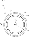
- FIG. 2 is a plan view seen from a reference numeral 2 in FIG. 1
- FIG. 3 is a section view taken along a reference numeral 3-3 indicated in FIG. 2
- FIG. 4 is an enlarged section view of a spot indicated by a reference numeral 4 in FIG. 3
- FIGs. 5A and 5B are section views of the vehicle thrust sliding bearing in a condition in which a load is unbalanced, wherein FIG. 5A is a section view of a side thereof on which the load acts largely more than that of FIG. 5B .
- the vehicle thrust sliding bearing 100 serving as a vehicle thrust bearing of the first embodiment of the invention includes an annular upper case 110 made of synthetic resin, an annular lower case 120 made of synthetic resin, and an annular sliding bearing piece 130 made of synthetic resin and serving as a bearing piece.
- the upper case 110 is configured to abut on a vehicle-side mount member VA serving as a vehicle body-side mount portion.
- the upper case 110 integrally includes an annular upper case base 111 forming an annular upper case top surface 111a and an annular upper case bottom surface 111b in an axial direction Y of a piston rod and mounted to a vehicle-side, an inner circumferential cylindrical portion 112 suspended from an inner circumferential end in a radial direction X of the upper case base 111, and an outer circumferential cylindrical portion 113 suspending from an outer circumferential end in the radial direction X of the upper case base 111.
- the lower case 120 is configured to overlap rotatably with respect to the upper case 110 around an axial center AX of the piston rod.
- the lower case 120 integrally includes an annular lower case base 121 rotatably overlapped with the upper case 110 around the axial center AX and an inner circumferential cylindrical portion 122 suspended from an inner radial direction of the lower case base 121.
- a base outer circumferential surface 121a is formed on a radial outer side of the lower case base 121.
- the base outer circumferential surface 121a and an outer annular step 121aa formed on the base outer circumferential surface 121a are provided with a ringed seal member 140 formed of synthetic rubber which is one example of an elastic material described later.
- an outer annular hook 113a is formed on the outer circumferential cylindrical portion 113 of the upper case 110.
- the outer annular hook 113a prevents the upper case 110 from disassembled from the lower case 120.
- an inner annular groove 122a is formed inside of the inner circumferential cylindrical portion 122 of the lower case 120.
- the inner annular groove 122a is provided such that it engages with an inner annular projection thread 112a formed at a lower end of the inner circumferential cylindrical portion 112 of the upper case 110 with a slight gap between them.
- the annular sliding bearing piece 130 is interposed within an annular space created between the upper case 110 and the lower case 120 and is configured to bear a thrust load applied.
- the annular sliding bearing piece 130 is provided in the annular space between the upper case bottom surface 111b of the upper case base 111 and a lower case top surface 121c of the lower case base 121.
- the annular sliding bearing piece 130 includes a bearing top surface 131 that comes into slidable contact with the upper case bottom surface 111b of the upper case base 111, and a bearing bottom surface 132 that comes into contact with the lower case top surface 121c of the lower case base 121 of the lower case 120.
- a sectional profile of the annular sliding bearing piece 130 viewed from a circumferential direction R can be formed into a shape of L for example so as to come into contact with both an outer circumferential surface of the inner circumferential cylindrical portion 112 of the upper case 110 and an inner circumferential surface of the inner circumferential cylindrical portion 122 of the lower case 120 to bear a radial load by the annular sliding bearing piece 130.
- a convex portion can be formed on one of the annular sliding bearing piece 130 and the lower case 120 and a concave portion engaging with the convex portion can be formed on the other one for example such that the annular sliding bearing piece 130 does not rotate with respect to the lower case 120.
- the ringed seal member 140 is formed of an elastic material and is provided between an inner circumferential surface 113b of the outer circumferential cylindrical portion 113 of the upper case 110 and the base outer circumferential surface 121a of the lower case base 121 of the lower case 120.
- the ringed seal member 140 includes an inner circumferential base 141 coming into contact with the base outer circumferential surface 121a of the lower case base 121 and an annular outer lip portion 142 extending to a radial outer side from the inner circumferential base 141 and coming into contact with an inner circumferential surface 113b of the outer circumferential cylindrical portion 113 of the upper case 110.
- the inner circumferential base 141 includes an inner micro-lip 141a coming into contact with an inner circumferential side of the outer annular step 121aa.
- the ringed seal member 140 is configured such that a contact part of the annular sliding bearing piece 130 with the upper case 110 and a contact part of the annular sliding bearing piece 130 with the lower case 120 are sealed at the case outer side to prevent muddy water or the like from infiltrating into a gap path RO between the upper case 110 and the lower case 120.
- a spring pad SP formed annularly of rubber is provided at a lower case bottom surface 121d of the lower case base 121.
- the vehicle thrust sliding bearing 100 is incorporated into a Strut type (MacPherson type) suspension by installing the vehicle thrust sliding bearing 100 between a vehicle-side seat surface VA1 of a vehicle-side mount member VA and a damper coil spring SS such that the upper case top surface 111a of the upper case 110 abuts on the vehicle-side seat surface VA1 of the vehicle-side mount member VA and the spring pad SP abuts on an upper end of the damper coil spring SS.
- a Strut type MacPherson type
- spring pad SP may be formed integrally with the lower case 120.
- annular sealing projection thread 111aa serving as an annular sealing projection thread portion configured abut on the vehicle-side mount member VA to seal a gap between the vehicle-side mount member VA and the upper case 110 is formed with dimensions of around 0.1 to 0.2 mm in height and 0.4 to 0.6 mm in width for example on the upper case top surface 111a of the upper case 110.
- the annular sealing projection thread 111aa is squashed corresponding to distribution of the thrust load in the circumferential direction R as illustrated in FIGs. 5A and 5B and seals the gap between the vehicle-side mount member VA and the upper case top surface 111a across a whole circumferential range.
- the annular sealing projection thread 111aa is provided within a projection range AR of the annular sliding bearing piece 130 in a view from the axial direction Y which is a thrust direction on the upper case top surface 111a.
- annular sealing projection thread 111aa is squashed more reliably and seals the gap between the vehicle-side mount member VA and the upper case top surface 111a across the whole circumferential range.
- the annular sealing projection thread 111aa is provided at the inner circumferential end within the projection range AR of the annular sliding bearing piece 130 in a view from the axial direction Y on the upper case top surface 111a.
- the thrust load received by the annular sliding bearing piece 130 becomes largest at the inner circumferential end of the annular sliding bearing piece 130, a torque radius becomes small and a rotation torque of the vehicle thrust sliding bearing 100 becomes small as compared to a case where the annular sealing projection thread 111aa is provided at an outer circumferential side.
- the vehicle thrust sliding bearing 100 serving as the vehicle thrust bearing of the first embodiment of the invention is configured such that the annular sealing projection thread 111aa serving as the annular sealing projection thread portion is formed on the upper case top surface 111a of the upper case 110, so that it is possible to avoid the muddy water or the like from infiltrating into the case from the case inner circumferential side by turning around the case inner circumferential side from the case outer circumferential side by passing through the gap between the vehicle-side mount member VA and the upper case top surface 111a even if the muddy water or the like try to enter from the gap between the vehicle-side mount member VA and the upper case top surface 111a from the case outer circumferential side.
- annular sliding bearing piece 130 serving as the sliding bearing piece made of synthetic resin and coming into contact with the upper case 110 and the lower case 120 to bear the thrust load is provided within the annular space created between the upper case 110 and the lower case 120 and the annular sealing projection thread 111aa is provided within the projection range AR of the annular sliding bearing piece 130 in a view from the axial direction Y which is the thrust direction on the upper case top surface 111a, the annular sealing projection thread 111aa is squashed more reliably and seals the gap between the vehicle-side mount member VA and the upper case top surface 111a around the whole circumferential range.
- annular sealing projection thread 111aa is provided at the inner circumferential end of the projection range AR of the annular sliding bearing piece 130 in the view from the axial direction Y on the upper case top surface 111a, a smooth steering operation can be assured.
- advantageous effects of the present embodiment are remarkable.
- FIG. 6A is an enlarged section view of a main part of the vehicle thrust sliding bearing 200 of a second embodiment of the present invention illustrating a condition in which a annular sealing projection thread 211aa is not yet squashed
- FIG. 6B is an enlarged section view of the main part illustrating a condition in which the annular sealing projection thread 211aa is squashed.
- the vehicle thrust sliding bearing 200 of the second embodiment is similar to the vehicle thrust sliding bearing 100 of the first embodiment except a sectional profile of the annular sealing projection thread 111aa viewed from the circumferential direction R is changed, and many components are common with those of the vehicle thrust sliding bearing 100 of the first embodiment.
- the common components will be simply denoted by reference numerals of 200s with common last two digits and the detailed description thereof will be omitted.
- the vehicle thrust sliding bearing 200 of the second embodiment of the invention is provided with an outer circumferential projection thread surface 211aaa of an annular sealing projection thread 211aa vertically to an upper case top surface 211a.
- the vehicle thrust sliding bearing 200 of the second embodiment of the invention is configured such that the outer circumferential projection thread surface 211aaa of the annular sealing projection thread 211aa is provided vertically with respect to the upper case top surface 211a, sealing can be enhanced more. Thus, the advantageous effect of the present embodiment is remarkable.
- FIG. 7 is a plan view of the vehicle thrust sliding bearing 300 of the third embodiment of the invention.
- the vehicle thrust sliding bearing 300 of the third embodiment is similar to the vehicle thrust sliding bearing 100 of the first embodiment except a profile of the annular sealing projection thread 111aa viewed from the axial direction Y is changed, and many components are common with those of the vehicle thrust sliding bearing 100 of the first embodiment.
- the common components will be denoted by reference numerals of 300s with common last two digits and the detailed description thereof will be omitted.
- annular sealing projection thread 311aa is formed into dodecagon as one example of the polygon in a view from the axial direction Y in the vehicle thrust sliding bearing 300 of the third embodiment of the invention.
- FIG. 8 is a plan view of the vehicle thrust sliding bearing 400 of the fourth embodiment of the invention.
- the vehicle thrust sliding bearing 400 of the fourth embodiment is similar to the vehicle thrust sliding bearing 100 of the first embodiment except a profile of the annular sealing projection thread 111aa viewed from the axial direction Y is changed twofold, and many components are common with those of the vehicle thrust sliding bearing 100 of the first embodiment.
- the common components will be denoted by reference numerals of 400s with common last two digits and the detailed description thereof will be omitted.
- an inner annular sealing projection thread 411Aaa and an outer annular sealing projection thread 411Baa are disposed so as to be twofold in a view from the axial direction Y.
Landscapes
- Engineering & Computer Science (AREA)
- General Engineering & Computer Science (AREA)
- Mechanical Engineering (AREA)
- Vehicle Body Suspensions (AREA)
- Sliding-Contact Bearings (AREA)
- Sealing Of Bearings (AREA)
- Fluid-Damping Devices (AREA)
Abstract
Description
- The present invention relates to a vehicle thrust bearing including an upper case and a lower case that are rotatable with respect to each other and more specifically, to a vehicle thrust bearing that is incorporated into a four-wheeled vehicle as a thrust bearing of a Strut type (MacPherson type) suspension or an air suspension of the vehicle.
- Hitherto, as a vehicle thrust bearing, there is known a slide bearing including an upper case made of synthetic resin and forming a ringed bottom surface in an axial direction of a piston rod used in a Strut-type suspension in a front wheel of a four-wheeled vehicle, a lower case made of synthetic resin overlapped rotatably with the upper case around the axial center, and a sliding bearing piece made of synthetic resin, disposed between the ringed bottom surface of the upper case and a ringed top surface of the lower case, and coming into contact with the ringed bottom surface of the upper case by a ringed top surface thereof and into with the ringed top surface of the lower case by a ringed bottom surface thereof (see Patent Literature 1, for example).
- [Patent Literature 1] Japanese Patent Laid-Open No.
2012-097904 FIGs. 2 and5 ) - However, the conventional sliding bearing described above has a problem that because an top surface of an upper ringed plate portion of the upper case in contact with a vehicle body-side mount portion is configured to be simply flat, there is a case when the upper case slightly deflects by an unbalanced load in the circumferential direction when a thrust load acts after when the sliding bearing is incorporated into the vehicle body-side mount portion. Then, a slight gap may be generated between the vehicle body-side mount portion and the top surface of the upper case, possibly allowing muddy water or the like to infiltrate into the case from a case inner circumferential side by turning around the case inner circumferential side from a case outer circumferential side by passing through the gap between the vehicle body-side mount portion and the upper case top surface.
- It is thus an object of the present invention to solve the above-described problem of the conventional art. The present invention provides a vehicle thrust bearing configured to avoid the muddy water or the like to infiltrate into the case from the case inner circumferential side by turning around the case inner circumferential side from the case outer circumferential side by passing through the gap between the vehicle body-side mount portion and the upper case top surface.
- In order to solve the abovementioned problem, according to a first aspect of the present invention, a vehicle thrust bearing including an annular upper case and an annular lower case overlapping with the upper case rotatably with respect to each other includes an annular seal projection thread formed on a top surface of the upper case upper case.
- In order to also solve the abovementioned problem, according to a second aspect of the present invention, in addition to the configuration of the vehicle thrust bearing as set forth in the first aspect, an annular sliding bearing piece made of synthetic resin and configured to bear a thrust load by being in contact with the upper case and the lower case is provided in an annular space created between the upper case and the lower case.
- In order to also solve the abovementioned problem, according to a third aspect of the present invention, in addition to the configuration of the vehicle thrust bearing as set forth in the second aspect, the annular sealing projection thread portion is provided within a projection range of the annular sliding bearing piece viewed from a thrust direction on the upper case top surface.
- In order to also solve the abovementioned problem, according to a fourth aspect of the present invention, in addition to the configuration of the vehicle thrust bearing as set forth in the third aspect, the annular sealing projection thread portion is provided at an inner circumferential end of the projection range of the annular sliding bearing piece viewed from the thrust direction on the upper case top surface.
- In order to also solve the abovementioned problem, according to a fifth aspect of the present invention, in addition to the configuration of the vehicle thrust bearing as set forth in any one of the first to fourth aspects, an outer circumferential projection thread surface of the annular sealing projection thread portion is provided vertically with respect to the upper case top surface.
- In order to also solve the abovementioned problem, according to a sixth aspect of the present invention, in addition to the configuration of the vehicle thrust bearing as set forth in any one of the first to fifth aspects, the upper case is disposed under a vehicle body-side mount portion and the annular sealing projection thread portion abuts on the vehicle body-side mount portion.
- In order to also solve the abovementioned problem, according to a seventh aspect of the present invention, in addition to the configuration of the vehicle thrust bearing as set forth in any one of the first to sixth aspects, the lower case overlaps with the upper case rotatably with respect to each other around an axial center of a piston rod used in a shock absorber of a vehicular suspension and bears a load from a damper coil spring of the suspension.
- Because the vehicle thrust bearing of the present invention includes the upper case and the lower case that overlaps with the upper case so as to be rotatable with respect to the upper case, the upper case and the lower case can rotate smoothly with respect to each other. In addition, the vehicle thrust bearing of the present invention can achieve the following unique effects.
- According to the vehicle thrust bearing of the invention of the first aspect, because the annular sealing projection thread is formed on the upper case top surface of the upper case, the annular sealing projection thread portion is squashed corresponding to a distribution of a thrust load in a circumferential direction when the vehicle thrust bearing is incorporated into the vehicle body-side mount portion and the thrust load acts. Then, the gap between the vehicle body-side mount portion and the upper case top surface is sealed across a whole circumferential range. Accordingly, it is possible to avoid muddy water or the like from infiltrating into the case from the case inner circumferential side by turning around the case inner circumferential side from the case outer circumferential side by passing through the gap between the vehicle-side mount member and the upper case top surface even if the muddy water or the like try to enter from the gap between the vehicle-side mount member and the upper case top surface from the case outer circumferential side.
- According to the vehicle thrust bearing of the invention of the second aspect in addition to the effect brought about by the invention of the first aspect, because the annular sliding bearing piece made of synthetic resin and configured to bear a thrust load by being in contact with the upper case and the lower case is provided in the annular space created between the upper case and the lower case, a friction resistance between the upper case and the lower case becomes small. Accordingly, the relative rotation of the upper case and the lower case can be smoothed more.
- According to the vehicle thrust bearing of the invention of the third aspect, in addition to the effect brought about by the invention of the second aspect, because the annular sealing projection thread portion is provided within a projection range of the annular sliding bearing piece viewed from a thrust direction on the upper case top surface, the thrust load acting on the annular sliding bearing piece also acts rigidly on the annular sealing projection thread portion. Accordingly, the annular sealing projection thread portion is squashed more reliably, and the gap between the vehicle body-side mount portion and the upper case top surface can be sealed across the whole circumferential range.
- According to the vehicle thrust bearing of the invention of the fourth aspect, in addition to the effect brought about by the invention of the third aspect, because the annular sealing projection thread portion is provided at an inner circumferential end of the projection range of the annular sliding bearing piece viewed from the thrust direction on the upper case top surface, the torque becomes small as compared to a case where the annular sealing projection thread portion is provided at an outer circumferential side. Thus, it is possible to reduce a burden of a vehicle body.
- According to the vehicle thrust bearing of the invention of the fifth aspect, in addition to the effect brought about by the invention of any one of the first to fourth aspects, because an outer circumferential projection thread surface of the annular sealing projection thread portion is provided vertically with respect to the upper case top surface, surface tension hardly acts on the muddy water or the like that try to infiltrate into the case as compared to a case where the outer circumferential projection thread surface is inclined with respect to the upper case top surface, and a capillary phenomenon hardly occurs. Accordingly, it is possible to enhance the sealing more.
- According to the vehicle thrust bearing of the invention of the sixth aspect, in addition to the effect brought about by the invention of any one of the first to fifth aspects, because the upper case is disposed under the vehicle body-side mount portion and the annular sealing projection thread portion abuts on the vehicle body-side mount portion, the annular sealing projection thread portion is positioned to be soft with respect to the vehicle body-side mount portion. Accordingly, the annular sealing projection thread portion is squashed more reliably, and the gap between the vehicle body-side mount portion and the upper case top surface can be sealed across the whole circumferential range.
- According to the vehicle thrust bearing of the invention of the seventh aspect, in addition to the effect brought about by the invention of any one of the first to sixth aspects, the lower case overlaps with the upper case rotatably with respect to each other around the axial center of the piston rod used in the shock absorber of the vehicular suspension and bears the load from the damper coil spring of the suspension. Accordingly, because the annular sealing projection thread portion is squashed corresponding to an unbalanced distribution of the thrust load, the gap between the vehicle body-side mount portion and the upper case top surface can be sealed across the whole circumferential range even in a case where the unbalanced load acts.
-
- FIG. 1
- is a partially sectional perspective view of a vehicle thrust sliding bearing of a first embodiment of the present invention.
- FIG. 2
- is a plan view seen from a
reference numeral 2 inFIG. 1 . - FIG. 3
- is a section view taken along a reference numeral 3-3 indicated in
FIG. 2 . - FIG. 4
- is an enlarged section view of a spot indicated by a reference numeral 4 in
FIG. 3 . - FIG. 5A
- is a section view of the vehicle thrust sliding bearing in a condition in which a load is unbalanced.
- FIG. 5B
- is a section view of the vehicle thrust sliding bearing in the condition in which the load is unbalanced.
- FIG. 6A
- is an enlarged section view of a main part of the vehicle thrust sliding bearing of a second embodiment of the present invention.
- FIG. 6B
- is an enlarged section view of the main part of the vehicle thrust sliding bearing of the second embodiment of the present invention.
- FIG. 7
- is a plan view of the vehicle thrust sliding bearing of a third embodiment of the present invention.
- FIG. 8
- is a plan view of the vehicle thrust sliding bearing of a fourth embodiment of the present invention.
- Specific embodiments of the present invention may take any configuration as long as a vehicle thrust bearing including an annular upper case and an annular lower case overlapping with the upper case rotatably with respect to each other further includes an annular sealing projection thread portion formed on an upper case top surface of the upper case and avoids muddy water or the like from infiltrating into the case from a case inner circumferential side by turning around the case inner circumferential side from a case outer circumferential side by passing through a gap between a vehicle-side mount portion and the upper case top surface even if the muddy water or the like try to enter from the gap between the vehicle-side mount portion and the upper case top surface from the case outer circumferential side.
- For example, the vehicle thrust bearing may include a bearing piece interposed in an annular space created between the upper case and the lower case and configured to bear a thrust load applied from a tire side, or may be configured such that the upper case slides directly with the lower case without including the bearing piece.
- In a case where the vehicle thrust bearing includes the bearing piece, the bearing piece may be a sliding bearing piece that slides with the upper case or the lower case or may be a rolling bearing piece that rollably keeps a rolling member such as a ball.
- A suspension of a vehicle may have any configuration as long as it has a configuration to which a thrust load is applied.
- The upper case may have any configuration as long as it abuts on the vehicle body-side mount portion. A strut type suspension, i.e., an exemplary suspension, may be either a type in which an upper end portion of a piston rod of a shock absorber is fitted into the vehicle body-side mount portion or a type in which it is fitted into the upper case.
- Still further, the shape of the annular sealing projection thread portion may be any shape such as a perfect circle, elliptical or polygonal, or may be doubled or tripled as long as the projection threads are linked in a shape of loop.
- A material forming the upper case may be thermoplastic synthetic resin such as polyacetal resin, polyamide resin, and polybutylene terephthalate resin.
- A material forming the lower case may be reinforced thermoplastic synthetic resin such as polyacetal resin, polyamide resin, and polybutylene terephthalate resin containing a reinforcing filler such as glass fiber, glass powder, carbon fiber by 0 to 50 mass %.
- A preferable exemplary material forming the sliding bearing piece is thermoplastic synthetic resin such as polyolefin resin containing polyacetal resin, polyamide resin, polybutylene terephthalate resin and polyethylene resin.
- A vehicle
thrust sliding bearing 100 of a first embodiment of the present invention will be described below with reference toFIGs. 1 through 5B . - Here,
FIG. 1 is a partially sectional perspective view of the vehiclethrust sliding bearing 100 of the first embodiment of the present invention,FIG. 2 is a plan view seen from areference numeral 2 inFIG. 1 ,FIG. 3 is a section view taken along a reference numeral 3-3 indicated inFIG. 2 ,FIG. 4 is an enlarged section view of a spot indicated by a reference numeral 4 inFIG. 3 ,andFIGs. 5A and 5B are section views of the vehicle thrust sliding bearing in a condition in which a load is unbalanced, whereinFIG. 5A is a section view of a side thereof on which the load acts largely more than that ofFIG. 5B . - As illustrated in
FIGs. 1 through 5B , the vehiclethrust sliding bearing 100 serving as a vehicle thrust bearing of the first embodiment of the invention includes an annularupper case 110 made of synthetic resin, an annularlower case 120 made of synthetic resin, and an annular slidingbearing piece 130 made of synthetic resin and serving as a bearing piece. - Among them, the
upper case 110 is configured to abut on a vehicle-side mount member VA serving as a vehicle body-side mount portion. - According to the present embodiment, the
upper case 110 integrally includes an annularupper case base 111 forming an annular upper casetop surface 111a and an annular upper casebottom surface 111b in an axial direction Y of a piston rod and mounted to a vehicle-side, an inner circumferentialcylindrical portion 112 suspended from an inner circumferential end in a radial direction X of theupper case base 111, and an outer circumferentialcylindrical portion 113 suspending from an outer circumferential end in the radial direction X of theupper case base 111. - The
lower case 120 is configured to overlap rotatably with respect to theupper case 110 around an axial center AX of the piston rod. - According to the present embodiment, the
lower case 120 integrally includes an annularlower case base 121 rotatably overlapped with theupper case 110 around the axial center AX and an inner circumferentialcylindrical portion 122 suspended from an inner radial direction of thelower case base 121. - A base outer
circumferential surface 121a is formed on a radial outer side of thelower case base 121. The base outercircumferential surface 121a and an outer annular step 121aa formed on the base outercircumferential surface 121a are provided with a ringedseal member 140 formed of synthetic rubber which is one example of an elastic material described later. - It is noted that an outer
annular hook 113a is formed on the outer circumferentialcylindrical portion 113 of theupper case 110. - Then, the relative move of the
upper case 110 and thelower case 120 in the axial direction Y is restricted by the outerannular hook 113a abutting on the ringedseal member 140. - That is, the outer
annular hook 113a prevents theupper case 110 from disassembled from thelower case 120. - Still further, an inner
annular groove 122a is formed inside of the inner circumferentialcylindrical portion 122 of thelower case 120. The innerannular groove 122a is provided such that it engages with an innerannular projection thread 112a formed at a lower end of the inner circumferentialcylindrical portion 112 of theupper case 110 with a slight gap between them. - The annular sliding
bearing piece 130 is interposed within an annular space created between theupper case 110 and thelower case 120 and is configured to bear a thrust load applied. - According to the present embodiment, the annular sliding
bearing piece 130 is provided in the annular space between the upper casebottom surface 111b of theupper case base 111 and a lower casetop surface 121c of thelower case base 121. - The annular sliding
bearing piece 130 includes a bearingtop surface 131 that comes into slidable contact with the upper casebottom surface 111b of theupper case base 111, and a bearingbottom surface 132 that comes into contact with the lower casetop surface 121c of thelower case base 121 of thelower case 120. - Note that it is needless to say that a sectional profile of the annular sliding
bearing piece 130 viewed from a circumferential direction R can be formed into a shape of L for example so as to come into contact with both an outer circumferential surface of the inner circumferentialcylindrical portion 112 of theupper case 110 and an inner circumferential surface of the inner circumferentialcylindrical portion 122 of thelower case 120 to bear a radial load by the annular slidingbearing piece 130. - Still further, a convex portion can be formed on one of the annular sliding
bearing piece 130 and thelower case 120 and a concave portion engaging with the convex portion can be formed on the other one for example such that the annular slidingbearing piece 130 does not rotate with respect to thelower case 120. Or, it is also possible to configure that the annular slidingbearing piece 130 rotates with respect to thelower case 120 without forming the convex and concave portions. - The ringed
seal member 140 is formed of an elastic material and is provided between an innercircumferential surface 113b of the outer circumferentialcylindrical portion 113 of theupper case 110 and the base outercircumferential surface 121a of thelower case base 121 of thelower case 120. - The ringed
seal member 140 includes an innercircumferential base 141 coming into contact with the base outercircumferential surface 121a of thelower case base 121 and an annularouter lip portion 142 extending to a radial outer side from the innercircumferential base 141 and coming into contact with an innercircumferential surface 113b of the outer circumferentialcylindrical portion 113 of theupper case 110. - Still further, the inner
circumferential base 141 includes aninner micro-lip 141a coming into contact with an inner circumferential side of the outer annular step 121aa. - Then, the ringed
seal member 140 is configured such that a contact part of the annular slidingbearing piece 130 with theupper case 110 and a contact part of the annular slidingbearing piece 130 with thelower case 120 are sealed at the case outer side to prevent muddy water or the like from infiltrating into a gap path RO between theupper case 110 and thelower case 120. - As illustrated in
FIGs. 3 and4 , a spring pad SP formed annularly of rubber is provided at a lower casebottom surface 121d of thelower case base 121. - The vehicle
thrust sliding bearing 100 is incorporated into a Strut type (MacPherson type) suspension by installing the vehiclethrust sliding bearing 100 between a vehicle-side seat surface VA1 of a vehicle-side mount member VA and a damper coil spring SS such that the upper casetop surface 111a of theupper case 110 abuts on the vehicle-side seat surface VA1 of the vehicle-side mount member VA and the spring pad SP abuts on an upper end of the damper coil spring SS. - It is noted that the spring pad SP may be formed integrally with the
lower case 120. - According to the present embodiment, as illustrated in
FIGs. 1 through 5B , an annular sealing projection thread 111aa serving as an annular sealing projection thread portion configured abut on the vehicle-side mount member VA to seal a gap between the vehicle-side mount member VA and theupper case 110 is formed with dimensions of around 0.1 to 0.2 mm in height and 0.4 to 0.6 mm in width for example on the upper casetop surface 111a of theupper case 110. - Thereby, when the vehicle
thrust sliding bearing 100 is incorporated into the vehicle-side mount member VA and a thrust load acts, the annular sealing projection thread 111aa is squashed corresponding to distribution of the thrust load in the circumferential direction R as illustrated inFIGs. 5A and 5B and seals the gap between the vehicle-side mount member VA and the upper casetop surface 111a across a whole circumferential range. - Still further, according to the present embodiment, the annular sealing projection thread 111aa is provided within a projection range AR of the annular sliding
bearing piece 130 in a view from the axial direction Y which is a thrust direction on the upper casetop surface 111a. - Thereby, the thrust load acting on the annular sliding
bearing piece 130 acts rigidly also on the annular sealing projection thread 111aa. - That is, the annular sealing projection thread 111aa is squashed more reliably and seals the gap between the vehicle-side mount member VA and the upper case
top surface 111a across the whole circumferential range. - Still further, according to the present embodiment, the annular sealing projection thread 111aa is provided at the inner circumferential end within the projection range AR of the annular sliding
bearing piece 130 in a view from the axial direction Y on the upper casetop surface 111a. - Thereby, the thrust load received by the annular sliding
bearing piece 130 becomes largest at the inner circumferential end of the annular slidingbearing piece 130, a torque radius becomes small and a rotation torque of the vehiclethrust sliding bearing 100 becomes small as compared to a case where the annular sealing projection thread 111aa is provided at an outer circumferential side. - The vehicle
thrust sliding bearing 100 serving as the vehicle thrust bearing of the first embodiment of the invention thus obtained is configured such that the annular sealing projection thread 111aa serving as the annular sealing projection thread portion is formed on the upper casetop surface 111a of theupper case 110, so that it is possible to avoid the muddy water or the like from infiltrating into the case from the case inner circumferential side by turning around the case inner circumferential side from the case outer circumferential side by passing through the gap between the vehicle-side mount member VA and the upper casetop surface 111a even if the muddy water or the like try to enter from the gap between the vehicle-side mount member VA and the upper casetop surface 111a from the case outer circumferential side. - Still further, because the annular sliding
bearing piece 130 serving as the sliding bearing piece made of synthetic resin and coming into contact with theupper case 110 and thelower case 120 to bear the thrust load is provided within the annular space created between theupper case 110 and thelower case 120 and the annular sealing projection thread 111aa is provided within the projection range AR of the annular slidingbearing piece 130 in a view from the axial direction Y which is the thrust direction on the upper casetop surface 111a, the annular sealing projection thread 111aa is squashed more reliably and seals the gap between the vehicle-side mount member VA and the upper casetop surface 111a around the whole circumferential range. - Still further, because the annular sealing projection thread 111aa is provided at the inner circumferential end of the projection range AR of the annular sliding
bearing piece 130 in the view from the axial direction Y on the upper casetop surface 111a, a smooth steering operation can be assured. Thus, advantageous effects of the present embodiment are remarkable. - Next, a vehicle
thrust sliding bearing 200 of a second embodiment of the present invention will be described with referenceFIGs. 6A and 6B . - Here,
FIG. 6A is an enlarged section view of a main part of the vehiclethrust sliding bearing 200 of a second embodiment of the present invention illustrating a condition in which a annular sealing projection thread 211aa is not yet squashed, andFIG. 6B is an enlarged section view of the main part illustrating a condition in which the annular sealing projection thread 211aa is squashed. - The vehicle
thrust sliding bearing 200 of the second embodiment is similar to the vehiclethrust sliding bearing 100 of the first embodiment except a sectional profile of the annular sealing projection thread 111aa viewed from the circumferential direction R is changed, and many components are common with those of the vehiclethrust sliding bearing 100 of the first embodiment. Thus, the common components will be simply denoted by reference numerals of 200s with common last two digits and the detailed description thereof will be omitted. - As illustrated in
FIG. 6A , the vehiclethrust sliding bearing 200 of the second embodiment of the invention is provided with an outer circumferential projection thread surface 211aaa of an annular sealing projection thread 211aa vertically to an upper casetop surface 211a. - Thereby, surface tension hardly acts on the muddy water or the like that try to infiltrate into the case as compared to a case where the outer circumferential projection thread surface 211aaa is inclined with respect to the upper case
top surface 211a, and a capillary phenomenon hardly occurs. - That is, almost no tension heading from the case outer circumferential side (right side in
FIG. 6A ) to the case inner circumferential side (left side inFIG. 6A ) acts on the muddy water or the like that try to infiltrate from the case outer circumferential side to the case inner circumferential side. - Still further, as illustrated in
FIG. 6B , the same effect is brought about also in a condition in which the annular sealing projection thread 211aa is squashed. - Because the vehicle
thrust sliding bearing 200 of the second embodiment of the invention thus obtained is configured such that the outer circumferential projection thread surface 211aaa of the annular sealing projection thread 211aa is provided vertically with respect to the upper casetop surface 211a, sealing can be enhanced more. Thus, the advantageous effect of the present embodiment is remarkable. - In succession, a vehicle
thrust sliding bearing 300 of a third embodiment of the invention will be described with reference toFIG. 7 . - Here,
FIG. 7 is a plan view of the vehiclethrust sliding bearing 300 of the third embodiment of the invention. - The vehicle
thrust sliding bearing 300 of the third embodiment is similar to the vehiclethrust sliding bearing 100 of the first embodiment except a profile of the annular sealing projection thread 111aa viewed from the axial direction Y is changed, and many components are common with those of the vehiclethrust sliding bearing 100 of the first embodiment. Thus, the common components will be denoted by reference numerals of 300s with common last two digits and the detailed description thereof will be omitted. - As illustrated in
FIG. 7 , an annular sealing projection thread 311aa is formed into dodecagon as one example of the polygon in a view from the axial direction Y in the vehiclethrust sliding bearing 300 of the third embodiment of the invention. - This arrangement makes it possible to obtain the same advantageous effects with the first embodiment described above.
- In succession, a vehicle
thrust sliding bearing 400 of a fourth embodiment of the invention will be described with reference toFIG. 8 . - Here,
FIG. 8 is a plan view of the vehiclethrust sliding bearing 400 of the fourth embodiment of the invention. - The vehicle
thrust sliding bearing 400 of the fourth embodiment is similar to the vehiclethrust sliding bearing 100 of the first embodiment except a profile of the annular sealing projection thread 111aa viewed from the axial direction Y is changed twofold, and many components are common with those of the vehiclethrust sliding bearing 100 of the first embodiment. Thus, the common components will be denoted by reference numerals of 400s with common last two digits and the detailed description thereof will be omitted. - As illustrated in
FIG. 8 , in the vehiclethrust sliding bearing 400 of the fourth embodiment of the invention, an inner annular sealing projection thread 411Aaa and an outer annular sealing projection thread 411Baa are disposed so as to be twofold in a view from the axial direction Y. - This arrangement makes it possible to obtain the same advantageous effects with the first embodiment described above.
-
- 100, 200, 300, 400
- vehicle thrust sliding bearing
- 110, 210,310, 410
- uppercase
- 111
- upper case base
- 111a, 211a, 311a, 411a
- upper case top surface
- 111aa 211aa, 311aa
- annular seal projection thread
- 411Aaa
- inner annular seal projection thread
- 411Baa
- outer annular seal projection thread
- 211aaa
- outer projection thread surface
- 111b
- upper case bottom surface
- 112
- inner circumference cylindrical portion
- 112a
- inner annular projection thread
- 113
- outer circumferential cylindrical portion
- 113a
- outer annular hook
- 113b
- inner circumferential surface
- 120
- lower case
- 121
- lower case base
- 121a
- base outer circumferential surface
- 121aa
- outer annular step
- 121c
- lower case top surface
- 121d
- lower case bottom surface
- 122
- inner circumferential cylindrical portion
- 122a
- inner annular groove
- 130
- annular sliding bearing piece (bearing piece)
- 131
- bearing top surface
- 132
- bearing bottom surface
- 140
- ringed sealing member
- 141
- inner circumferential base
- 141a
- inner micro-lip
- 142
- annular outer lip portion
- AX
- axial center of piston rod
- AR
- projection range of annular sliding bearing piece viewed from axial direction
- R
- circumferential direction
- RO
- gap path
- SS
- damper coil spring
- SP
- spring pad
- VA
- vehicle-side mount member (vehicle body-side mount portion)
- VA1
- vehicle-side seat surface
- X
- radial direction
- Y
- axial direction
Claims (7)
- A vehicle thrust bearing, comprising:an annular upper case that is in contact witha vehicle body-side mount portion; andan annular lower case overlapping with the upper case rotatably with respect to each other, the upper case being provided with an annular sealing projection thread portion formed on an upper case top surface of the upper case.
- The vehicle thrust bearing according to claim 1, wherein an annular sliding bearing piece made of synthetic resin and configured to bear a thrust load by being in contact with the upper case and the lower case is provided in an annular space created between the upper case and the lower case.
- The vehicle thrust bearing according to claim 2, wherein the annular sealing projection thread portion is provided within a projection range of the annular sliding bearing piece viewed from a thrust direction on the upper case top surface.
- The vehicle thrust bearing according to claim 3, wherein the annular sealing projection thread portion is provided at an inner circumferential end of the projection range of the annular sliding bearing piece viewed from the thrust direction on the upper case top surface.
- The vehicle thrust bearing according to any one of claims 1 through 4, wherein an outer circumferential projection thread surface of the annular sealing projection thread portion is provided vertically with respect to the upper case top surface.
- The vehicle thrust bearing according to any one of claims 1 through 5, wherein the upper case is disposed under a vehicle body-side mount portion and the annular sealing projection thread portion abuts on the vehicle body-side mount portion.
- The vehicle thrust bearing according to any one of claims 1 through 6, wherein the lower case overlaps with the upper case rotatably with respect to each other around an axial center of a piston rod used in a shock absorber of a vehicular suspension and bears a load from a damper coil spring of the suspension.
Applications Claiming Priority (2)
| Application Number | Priority Date | Filing Date | Title |
|---|---|---|---|
| JP2015091814A JP2016205600A (en) | 2015-04-28 | 2015-04-28 | Thrust bearing for vehicle |
| PCT/JP2016/062044 WO2016175041A1 (en) | 2015-04-28 | 2016-04-14 | Thrust bearing for vehicle |
Publications (2)
| Publication Number | Publication Date |
|---|---|
| EP3290727A1 true EP3290727A1 (en) | 2018-03-07 |
| EP3290727A4 EP3290727A4 (en) | 2019-01-16 |
Family
ID=57199692
Family Applications (1)
| Application Number | Title | Priority Date | Filing Date |
|---|---|---|---|
| EP16786318.2A Withdrawn EP3290727A4 (en) | 2015-04-28 | 2016-04-14 | Thrust bearing for vehicle |
Country Status (3)
| Country | Link |
|---|---|
| EP (1) | EP3290727A4 (en) |
| JP (1) | JP2016205600A (en) |
| WO (1) | WO2016175041A1 (en) |
Families Citing this family (1)
| Publication number | Priority date | Publication date | Assignee | Title |
|---|---|---|---|---|
| DE102020200586A1 (en) * | 2020-01-20 | 2021-07-22 | Aktiebolaget Skf | Suspension thrust bearing device |
Family Cites Families (6)
| Publication number | Priority date | Publication date | Assignee | Title |
|---|---|---|---|---|
| FR2899154B1 (en) * | 2006-03-31 | 2017-08-11 | Roulements Soc Nouvelle | VEHICLE SUSPENSION STOP DEVICE |
| JP2008014463A (en) * | 2006-07-07 | 2008-01-24 | Oiles Ind Co Ltd | Thrust sliding bearing, and thrust sliding bearing and piston rod combined mechanism |
| JP5299613B2 (en) * | 2008-09-16 | 2013-09-25 | 株式会社ジェイテクト | Thrust bearing |
| JP5704625B2 (en) * | 2009-12-11 | 2015-04-22 | オイレス工業株式会社 | Synthetic plastic thrust plain bearing |
| US9011009B2 (en) * | 2011-04-21 | 2015-04-21 | Illinois Tool Works Inc. | Direct acting endlink seal |
| FR2990252B1 (en) * | 2012-05-04 | 2015-01-02 | Skf Ab | METHOD FOR MANUFACTURING A SUSPENSION STOP DEVICE, DEVICE AND FORCE LEG COMPRISING SUCH A DEVICE |
-
2015
- 2015-04-28 JP JP2015091814A patent/JP2016205600A/en active Pending
-
2016
- 2016-04-14 WO PCT/JP2016/062044 patent/WO2016175041A1/en not_active Ceased
- 2016-04-14 EP EP16786318.2A patent/EP3290727A4/en not_active Withdrawn
Also Published As
| Publication number | Publication date |
|---|---|
| EP3290727A4 (en) | 2019-01-16 |
| WO2016175041A1 (en) | 2016-11-03 |
| JP2016205600A (en) | 2016-12-08 |
Similar Documents
| Publication | Publication Date | Title |
|---|---|---|
| KR102116286B1 (en) | Strut bearing | |
| US8684607B2 (en) | Thrust sliding bearing and combination mechanism of the thrust sliding bearing and piston rod with coil spring | |
| EP1365162B1 (en) | Synthetic resin sliding bearing | |
| US9964145B2 (en) | Suspension thrust bearing device | |
| US8066435B2 (en) | Strut sliding bearing | |
| EP2952762B1 (en) | Synthetic resin sliding bearing | |
| US8708568B2 (en) | Synthetic resin-made thrust sliding bearing | |
| EP2806177B1 (en) | Thrust sliding bearing | |
| US7273317B2 (en) | Thrust sliding bearing | |
| US8256965B2 (en) | Thrust sliding bearing and combination mechanism of the thrust sliding bearing and a piston rod | |
| US10029532B2 (en) | Strut bearing with a two-component cap | |
| US8596661B2 (en) | Thrust sliding bearing and combination mechanism of the thrust sliding bearing and a piston rod | |
| US20180370317A1 (en) | Slide bearing | |
| US9415656B2 (en) | Synthetic resin-made slide bearing | |
| US8876399B2 (en) | Suspension strut bearing | |
| US9062708B2 (en) | Thrust sliding bearing | |
| CN106958592B (en) | Synthetic resin sliding bearing | |
| JP2014202360A (en) | Suspension thrust bearing device and suspension strut equipped with such thrust bearing | |
| JP4325198B2 (en) | Synthetic resin sliding bearing and mounting structure of strut suspension using this sliding bearing | |
| US10060471B2 (en) | Thrust sliding bearing | |
| JP2016142308A (en) | Thrust bearing for vehicle | |
| US20180236837A1 (en) | Suspension Strut Bearing | |
| WO2016175041A1 (en) | Thrust bearing for vehicle | |
| US20200171905A1 (en) | Bearing and suspension | |
| EP3282140A1 (en) | Thrust bearing for vehicles |
Legal Events
| Date | Code | Title | Description |
|---|---|---|---|
| PUAI | Public reference made under article 153(3) epc to a published international application that has entered the european phase |
Free format text: ORIGINAL CODE: 0009012 |
|
| 17P | Request for examination filed |
Effective date: 20171109 |
|
| AK | Designated contracting states |
Kind code of ref document: A1 Designated state(s): AL AT BE BG CH CY CZ DE DK EE ES FI FR GB GR HR HU IE IS IT LI LT LU LV MC MK MT NL NO PL PT RO RS SE SI SK SM TR |
|
| AX | Request for extension of the european patent |
Extension state: BA ME |
|
| DAV | Request for validation of the european patent (deleted) | ||
| DAX | Request for extension of the european patent (deleted) | ||
| A4 | Supplementary search report drawn up and despatched |
Effective date: 20181213 |
|
| RIC1 | Information provided on ipc code assigned before grant |
Ipc: F16C 33/08 20060101AFI20181207BHEP Ipc: B60G 15/06 20060101ALI20181207BHEP Ipc: F16C 17/04 20060101ALI20181207BHEP Ipc: F16C 35/02 20060101ALI20181207BHEP Ipc: F16C 33/58 20060101ALI20181207BHEP Ipc: F16C 33/74 20060101ALI20181207BHEP |
|
| STAA | Information on the status of an ep patent application or granted ep patent |
Free format text: STATUS: THE APPLICATION IS DEEMED TO BE WITHDRAWN |
|
| 18D | Application deemed to be withdrawn |
Effective date: 20190719 |