EP3290714A1 - Ventilation fan having air bearing system - Google Patents
Ventilation fan having air bearing system Download PDFInfo
- Publication number
- EP3290714A1 EP3290714A1 EP17188731.8A EP17188731A EP3290714A1 EP 3290714 A1 EP3290714 A1 EP 3290714A1 EP 17188731 A EP17188731 A EP 17188731A EP 3290714 A1 EP3290714 A1 EP 3290714A1
- Authority
- EP
- European Patent Office
- Prior art keywords
- shaft
- housing
- rotor
- port
- bearing
- Prior art date
- Legal status (The legal status is an assumption and is not a legal conclusion. Google has not performed a legal analysis and makes no representation as to the accuracy of the status listed.)
- Granted
Links
Images


Classifications
-
- F—MECHANICAL ENGINEERING; LIGHTING; HEATING; WEAPONS; BLASTING
- F04—POSITIVE - DISPLACEMENT MACHINES FOR LIQUIDS; PUMPS FOR LIQUIDS OR ELASTIC FLUIDS
- F04D—NON-POSITIVE-DISPLACEMENT PUMPS
- F04D25/00—Pumping installations or systems
- F04D25/02—Units comprising pumps and their driving means
- F04D25/08—Units comprising pumps and their driving means the working fluid being air, e.g. for ventilation
-
- B—PERFORMING OPERATIONS; TRANSPORTING
- B64—AIRCRAFT; AVIATION; COSMONAUTICS
- B64D—EQUIPMENT FOR FITTING IN OR TO AIRCRAFT; FLIGHT SUITS; PARACHUTES; ARRANGEMENT OR MOUNTING OF POWER PLANTS OR PROPULSION TRANSMISSIONS IN AIRCRAFT
- B64D13/00—Arrangements or adaptations of air-treatment apparatus for aircraft crew or passengers, or freight space
- B64D13/06—Arrangements or adaptations of air-treatment apparatus for aircraft crew or passengers, or freight space the air being conditioned
-
- F—MECHANICAL ENGINEERING; LIGHTING; HEATING; WEAPONS; BLASTING
- F04—POSITIVE - DISPLACEMENT MACHINES FOR LIQUIDS; PUMPS FOR LIQUIDS OR ELASTIC FLUIDS
- F04D—NON-POSITIVE-DISPLACEMENT PUMPS
- F04D19/00—Axial-flow pumps
- F04D19/002—Axial flow fans
-
- F—MECHANICAL ENGINEERING; LIGHTING; HEATING; WEAPONS; BLASTING
- F04—POSITIVE - DISPLACEMENT MACHINES FOR LIQUIDS; PUMPS FOR LIQUIDS OR ELASTIC FLUIDS
- F04D—NON-POSITIVE-DISPLACEMENT PUMPS
- F04D25/00—Pumping installations or systems
- F04D25/02—Units comprising pumps and their driving means
- F04D25/06—Units comprising pumps and their driving means the pump being electrically driven
-
- F—MECHANICAL ENGINEERING; LIGHTING; HEATING; WEAPONS; BLASTING
- F04—POSITIVE - DISPLACEMENT MACHINES FOR LIQUIDS; PUMPS FOR LIQUIDS OR ELASTIC FLUIDS
- F04D—NON-POSITIVE-DISPLACEMENT PUMPS
- F04D25/00—Pumping installations or systems
- F04D25/02—Units comprising pumps and their driving means
- F04D25/08—Units comprising pumps and their driving means the working fluid being air, e.g. for ventilation
- F04D25/082—Units comprising pumps and their driving means the working fluid being air, e.g. for ventilation the unit having provision for cooling the motor
-
- F—MECHANICAL ENGINEERING; LIGHTING; HEATING; WEAPONS; BLASTING
- F04—POSITIVE - DISPLACEMENT MACHINES FOR LIQUIDS; PUMPS FOR LIQUIDS OR ELASTIC FLUIDS
- F04D—NON-POSITIVE-DISPLACEMENT PUMPS
- F04D29/00—Details, component parts, or accessories
- F04D29/04—Shafts or bearings, or assemblies thereof
-
- F—MECHANICAL ENGINEERING; LIGHTING; HEATING; WEAPONS; BLASTING
- F04—POSITIVE - DISPLACEMENT MACHINES FOR LIQUIDS; PUMPS FOR LIQUIDS OR ELASTIC FLUIDS
- F04D—NON-POSITIVE-DISPLACEMENT PUMPS
- F04D29/00—Details, component parts, or accessories
- F04D29/04—Shafts or bearings, or assemblies thereof
- F04D29/043—Shafts
-
- F—MECHANICAL ENGINEERING; LIGHTING; HEATING; WEAPONS; BLASTING
- F04—POSITIVE - DISPLACEMENT MACHINES FOR LIQUIDS; PUMPS FOR LIQUIDS OR ELASTIC FLUIDS
- F04D—NON-POSITIVE-DISPLACEMENT PUMPS
- F04D29/00—Details, component parts, or accessories
- F04D29/05—Shafts or bearings, or assemblies thereof, specially adapted for elastic fluid pumps
- F04D29/051—Axial thrust balancing
-
- F—MECHANICAL ENGINEERING; LIGHTING; HEATING; WEAPONS; BLASTING
- F04—POSITIVE - DISPLACEMENT MACHINES FOR LIQUIDS; PUMPS FOR LIQUIDS OR ELASTIC FLUIDS
- F04D—NON-POSITIVE-DISPLACEMENT PUMPS
- F04D29/00—Details, component parts, or accessories
- F04D29/05—Shafts or bearings, or assemblies thereof, specially adapted for elastic fluid pumps
- F04D29/051—Axial thrust balancing
- F04D29/0513—Axial thrust balancing hydrostatic; hydrodynamic thrust bearings
-
- F—MECHANICAL ENGINEERING; LIGHTING; HEATING; WEAPONS; BLASTING
- F04—POSITIVE - DISPLACEMENT MACHINES FOR LIQUIDS; PUMPS FOR LIQUIDS OR ELASTIC FLUIDS
- F04D—NON-POSITIVE-DISPLACEMENT PUMPS
- F04D29/00—Details, component parts, or accessories
- F04D29/05—Shafts or bearings, or assemblies thereof, specially adapted for elastic fluid pumps
- F04D29/056—Bearings
- F04D29/057—Bearings hydrostatic; hydrodynamic
-
- F—MECHANICAL ENGINEERING; LIGHTING; HEATING; WEAPONS; BLASTING
- F04—POSITIVE - DISPLACEMENT MACHINES FOR LIQUIDS; PUMPS FOR LIQUIDS OR ELASTIC FLUIDS
- F04D—NON-POSITIVE-DISPLACEMENT PUMPS
- F04D29/00—Details, component parts, or accessories
- F04D29/18—Rotors
- F04D29/181—Axial flow rotors
-
- F—MECHANICAL ENGINEERING; LIGHTING; HEATING; WEAPONS; BLASTING
- F04—POSITIVE - DISPLACEMENT MACHINES FOR LIQUIDS; PUMPS FOR LIQUIDS OR ELASTIC FLUIDS
- F04D—NON-POSITIVE-DISPLACEMENT PUMPS
- F04D29/00—Details, component parts, or accessories
- F04D29/26—Rotors specially for elastic fluids
- F04D29/32—Rotors specially for elastic fluids for axial flow pumps
- F04D29/325—Rotors specially for elastic fluids for axial flow pumps for axial flow fans
-
- F—MECHANICAL ENGINEERING; LIGHTING; HEATING; WEAPONS; BLASTING
- F04—POSITIVE - DISPLACEMENT MACHINES FOR LIQUIDS; PUMPS FOR LIQUIDS OR ELASTIC FLUIDS
- F04D—NON-POSITIVE-DISPLACEMENT PUMPS
- F04D29/00—Details, component parts, or accessories
- F04D29/40—Casings; Connections of working fluid
- F04D29/52—Casings; Connections of working fluid for axial pumps
- F04D29/522—Casings; Connections of working fluid for axial pumps especially adapted for elastic fluid pumps
-
- F—MECHANICAL ENGINEERING; LIGHTING; HEATING; WEAPONS; BLASTING
- F04—POSITIVE - DISPLACEMENT MACHINES FOR LIQUIDS; PUMPS FOR LIQUIDS OR ELASTIC FLUIDS
- F04D—NON-POSITIVE-DISPLACEMENT PUMPS
- F04D29/00—Details, component parts, or accessories
- F04D29/58—Cooling; Heating; Diminishing heat transfer
- F04D29/5806—Cooling the drive system
-
- F—MECHANICAL ENGINEERING; LIGHTING; HEATING; WEAPONS; BLASTING
- F16—ENGINEERING ELEMENTS AND UNITS; GENERAL MEASURES FOR PRODUCING AND MAINTAINING EFFECTIVE FUNCTIONING OF MACHINES OR INSTALLATIONS; THERMAL INSULATION IN GENERAL
- F16C—SHAFTS; FLEXIBLE SHAFTS; ELEMENTS OR CRANKSHAFT MECHANISMS; ROTARY BODIES OTHER THAN GEARING ELEMENTS; BEARINGS
- F16C17/00—Sliding-contact bearings for exclusively rotary movement
- F16C17/02—Sliding-contact bearings for exclusively rotary movement for radial load only
- F16C17/024—Sliding-contact bearings for exclusively rotary movement for radial load only with flexible leaves to create hydrodynamic wedge, e.g. radial foil bearings
-
- F—MECHANICAL ENGINEERING; LIGHTING; HEATING; WEAPONS; BLASTING
- F16—ENGINEERING ELEMENTS AND UNITS; GENERAL MEASURES FOR PRODUCING AND MAINTAINING EFFECTIVE FUNCTIONING OF MACHINES OR INSTALLATIONS; THERMAL INSULATION IN GENERAL
- F16C—SHAFTS; FLEXIBLE SHAFTS; ELEMENTS OR CRANKSHAFT MECHANISMS; ROTARY BODIES OTHER THAN GEARING ELEMENTS; BEARINGS
- F16C32/00—Bearings not otherwise provided for
- F16C32/06—Bearings not otherwise provided for with moving member supported by a fluid cushion formed, at least to a large extent, otherwise than by movement of the shaft, e.g. hydrostatic air-cushion bearings
- F16C32/0603—Bearings not otherwise provided for with moving member supported by a fluid cushion formed, at least to a large extent, otherwise than by movement of the shaft, e.g. hydrostatic air-cushion bearings supported by a gas cushion, e.g. an air cushion
- F16C32/0614—Bearings not otherwise provided for with moving member supported by a fluid cushion formed, at least to a large extent, otherwise than by movement of the shaft, e.g. hydrostatic air-cushion bearings supported by a gas cushion, e.g. an air cushion the gas being supplied under pressure, e.g. aerostatic bearings
-
- F—MECHANICAL ENGINEERING; LIGHTING; HEATING; WEAPONS; BLASTING
- F16—ENGINEERING ELEMENTS AND UNITS; GENERAL MEASURES FOR PRODUCING AND MAINTAINING EFFECTIVE FUNCTIONING OF MACHINES OR INSTALLATIONS; THERMAL INSULATION IN GENERAL
- F16C—SHAFTS; FLEXIBLE SHAFTS; ELEMENTS OR CRANKSHAFT MECHANISMS; ROTARY BODIES OTHER THAN GEARING ELEMENTS; BEARINGS
- F16C32/00—Bearings not otherwise provided for
- F16C32/06—Bearings not otherwise provided for with moving member supported by a fluid cushion formed, at least to a large extent, otherwise than by movement of the shaft, e.g. hydrostatic air-cushion bearings
- F16C32/0603—Bearings not otherwise provided for with moving member supported by a fluid cushion formed, at least to a large extent, otherwise than by movement of the shaft, e.g. hydrostatic air-cushion bearings supported by a gas cushion, e.g. an air cushion
- F16C32/0614—Bearings not otherwise provided for with moving member supported by a fluid cushion formed, at least to a large extent, otherwise than by movement of the shaft, e.g. hydrostatic air-cushion bearings supported by a gas cushion, e.g. an air cushion the gas being supplied under pressure, e.g. aerostatic bearings
- F16C32/0625—Bearings not otherwise provided for with moving member supported by a fluid cushion formed, at least to a large extent, otherwise than by movement of the shaft, e.g. hydrostatic air-cushion bearings supported by a gas cushion, e.g. an air cushion the gas being supplied under pressure, e.g. aerostatic bearings via supply slits
-
- H—ELECTRICITY
- H02—GENERATION; CONVERSION OR DISTRIBUTION OF ELECTRIC POWER
- H02K—DYNAMO-ELECTRIC MACHINES
- H02K5/00—Casings; Enclosures; Supports
- H02K5/04—Casings or enclosures characterised by the shape, form or construction thereof
- H02K5/16—Means for supporting bearings, e.g. insulating supports or means for fitting bearings in the bearing-shields
- H02K5/167—Means for supporting bearings, e.g. insulating supports or means for fitting bearings in the bearing-shields using sliding-contact or spherical cap bearings
- H02K5/1672—Means for supporting bearings, e.g. insulating supports or means for fitting bearings in the bearing-shields using sliding-contact or spherical cap bearings radially supporting the rotary shaft at both ends of the rotor
-
- H—ELECTRICITY
- H02—GENERATION; CONVERSION OR DISTRIBUTION OF ELECTRIC POWER
- H02K—DYNAMO-ELECTRIC MACHINES
- H02K7/00—Arrangements for handling mechanical energy structurally associated with dynamo-electric machines, e.g. structural association with mechanical driving motors or auxiliary dynamo-electric machines
- H02K7/14—Structural association with mechanical loads, e.g. with hand-held machine tools or fans
-
- B—PERFORMING OPERATIONS; TRANSPORTING
- B64—AIRCRAFT; AVIATION; COSMONAUTICS
- B64D—EQUIPMENT FOR FITTING IN OR TO AIRCRAFT; FLIGHT SUITS; PARACHUTES; ARRANGEMENT OR MOUNTING OF POWER PLANTS OR PROPULSION TRANSMISSIONS IN AIRCRAFT
- B64D13/00—Arrangements or adaptations of air-treatment apparatus for aircraft crew or passengers, or freight space
- B64D13/06—Arrangements or adaptations of air-treatment apparatus for aircraft crew or passengers, or freight space the air being conditioned
- B64D2013/0603—Environmental Control Systems
-
- F—MECHANICAL ENGINEERING; LIGHTING; HEATING; WEAPONS; BLASTING
- F16—ENGINEERING ELEMENTS AND UNITS; GENERAL MEASURES FOR PRODUCING AND MAINTAINING EFFECTIVE FUNCTIONING OF MACHINES OR INSTALLATIONS; THERMAL INSULATION IN GENERAL
- F16C—SHAFTS; FLEXIBLE SHAFTS; ELEMENTS OR CRANKSHAFT MECHANISMS; ROTARY BODIES OTHER THAN GEARING ELEMENTS; BEARINGS
- F16C2326/00—Articles relating to transporting
- F16C2326/43—Aeroplanes; Helicopters
-
- F—MECHANICAL ENGINEERING; LIGHTING; HEATING; WEAPONS; BLASTING
- F16—ENGINEERING ELEMENTS AND UNITS; GENERAL MEASURES FOR PRODUCING AND MAINTAINING EFFECTIVE FUNCTIONING OF MACHINES OR INSTALLATIONS; THERMAL INSULATION IN GENERAL
- F16C—SHAFTS; FLEXIBLE SHAFTS; ELEMENTS OR CRANKSHAFT MECHANISMS; ROTARY BODIES OTHER THAN GEARING ELEMENTS; BEARINGS
- F16C2360/00—Engines or pumps
- F16C2360/46—Fans, e.g. ventilators
-
- H—ELECTRICITY
- H02—GENERATION; CONVERSION OR DISTRIBUTION OF ELECTRIC POWER
- H02K—DYNAMO-ELECTRIC MACHINES
- H02K9/00—Arrangements for cooling or ventilating
- H02K9/02—Arrangements for cooling or ventilating by ambient air flowing through the machine
- H02K9/04—Arrangements for cooling or ventilating by ambient air flowing through the machine having means for generating a flow of cooling medium
- H02K9/06—Arrangements for cooling or ventilating by ambient air flowing through the machine having means for generating a flow of cooling medium with fans or impellers driven by the machine shaft
Definitions
- Aircraft ventilation fans are used to move conditioned air to various locations of the aircraft such as the cockpit or cabin.
- the aircraft ventilation fans may use ball bearings to rotatably support rotating components.
- a ventilation fan includes a shaft assembly, a rotor, a motor housing, a first opening, and a bearing housing.
- the shaft assembly extends along an axis and is disposed within a housing assembly.
- the shaft assembly includes a first shaft having a first shaft first portion that defines a first port, and a first shaft second portion that defines a second port.
- the first shaft is operatively connected to a second shaft having a second shaft first portion that defines a third port.
- the second shaft further having a second shaft second portion.
- the rotor has a rotor first portion disposed about the first shaft first portion and a rotor second portion that extends from the rotor first portion.
- the rotor first portion defines a rotor port.
- the motor housing is disposed about the first shaft second portion.
- the motor housing has a housing arm, a housing leg that extends from the housing arm, a housing extension that extends from the housing leg, and a vane platform that extends from the housing extension.
- the first opening is defined between respective ends of the rotor second portion and the vane platform.
- the bearing housing is operatively connected to the motor housing.
- the bearing housing is disposed about the second shaft second portion.
- the bearing housing has a bearing arm, a bearing leg that extends from the bearing arm, and a bearing extension that extends from the bearing leg.
- a first journal air bearing rotatably supports the shaft assembly.
- the first journal air bearing is positioned radially between the housing arm and the first shaft second portion and positioned axially between the first port and the second port.
- an inner surface of the first journal air bearing and an outer surface of the first shaft second portion define a first journal air bearing flow path.
- a thrust plate positioned radially between the first shaft second portion and the rotor second portion and positioned axially between the rotor first portion and the housing leg; a thrust runner positioned axially between the thrust plate and the housing leg; and a thrust air bearing disposed between the thrust runner and at least one of the thrust plate and the housing leg.
- the first shaft second portion defines a thrust runner positioned axially between the thrust plate and the housing leg.
- the thrust plate defines a thrust port.
- the first opening is in fluid communication with the thrust port, the first journal air bearing flow path, the second port, the first port, and the rotor port to define a first flow path.
- a second journal air bearing positioned radially between the bearing arm and the second shaft second portion.
- an inner surface of the second journal air bearing and an outer surface of the second shaft second portion define a second journal air bearing flow path.
- the bearing housing defines a second opening.
- the second opening is in fluid communication with the second journal air bearing flow path and the third port to define a second flow path.
- a ventilation fan includes a shaft assembly, a rotor, a motor housing, and a bearing housing.
- the shaft assembly includes a first shaft, a second shaft, and a third shaft.
- the first shaft has a first shaft first portion and a first shaft second portion.
- the first shaft second portion defines a first port.
- the first shaft is operatively connected to the second shaft.
- the second shaft defines a second port.
- the third shaft is operatively connected to the second shaft.
- the rotor has a rotor first portion disposed about the first shaft first portion and a rotor second portion that extends from the rotor first portion.
- the rotor first portion defines a rotor port.
- the motor housing is disposed about the first shaft second portion.
- the motor housing has a housing arm, a housing leg that extends from the housing arm, and a vane platform that extends from the housing extension.
- the vane platform defines a housing port.
- the bearing housing is operatively connected to the motor housing.
- the bearing housing is disposed about the third shaft.
- the bearing housing has a bearing arm and a bearing leg that extends from the bearing arm.
- a thrust plate positioned axially between the rotor second portion and the housing leg, wherein the thrust plate defines a thrust port.
- a first opening is defined between respective ends of the rotor second portion and the thrust plate.
- the first shaft second portion defines a thrust runner positioned axially between the thrust plate and the housing leg.
- a first journal air bearing positioned radially between the bearing arm and the second shaft second portion, wherein an inner surface of the first journal air bearing and an outer surface of the third shaft define a first journal air bearing flow path.
- the first opening is in fluid communication with the thrust port, the first journal air bearing flow path, the second port, the first port, and the rotor port to define a first flow path.
- a second journal air bearing positioned radially between the bearing arm and the third shaft, wherein an inner surface of the second journal air bearing and an outer surface of the third shaft define a second journal air bearing flow path.
- the bearing housing defines a second opening.
- the second opening is in fluid communication with the second journal air bearing flow path, the housing port, and the second port to define a second flow path.
- Aircraft may include a cockpit or cabin ventilation system.
- the cockpit or cabin ventilation system may be provided as part of a larger environmental control system.
- the environment control system is configured to receive ambient air, condition the ambient air, and provide the conditioned air to various systems such as the cockpit or cabin ventilation system.
- the conditioned air may be provided to the cockpit or cabin through a ventilation fan 10.
- the ventilation fan 10 includes a housing assembly 20, a shaft assembly 22, a rotor 24, a motor housing 26, a bearing housing 28, a thrust plate 30, and an air bearing system 32.
- the housing assembly 20 includes a first housing 40 that is operatively connected to a second housing 42 and a check valve assembly 44 that is operatively connected to the second housing 42.
- the first housing 40 and the second housing 42 cooperate to define a cavity 46 that may receive various components of the ventilation fan 10.
- the first housing 40 defines a fan section inlet at a first end 50 of the first housing 40 and a fan section outlet at a second end 52 of the first housing 40.
- the first end 50 may have a first diameter and the second end 52 may have a second diameter that is greater than the first diameter.
- the second housing 42 defines a rotor section inlet at a first end 54 of the second housing 42 and a rotor section outlet at a second end 56 of the second housing 42.
- the first end 54 may have a first diameter and the second end 56 may have a second diameter that is substantially equal to the first diameter.
- the first end 54 of the second housing 42 is operatively connected to the second end 52 of the first housing 40.
- the check valve assembly 44 is disposed proximate the second end 56 of the second housing 42.
- the check valve assembly 44 includes a mounting frame 60, a valve plate 62, and a valve mechanism 64.
- the mounting frame 60 is disposed on an interior surface of the second housing 42.
- the valve plate 62 is operatively connected to the second housing 42 via the mounting frame 60.
- the valve plate 62 defines an opening that is configured to receive the valve mechanism 64.
- the valve mechanism 64 is configured as a one-way valve to inhibit backflow through the ventilation fan 10.
- the shaft assembly 22 is disposed within the cavity 46 of the housing assembly 20.
- the shaft assembly 22 extends along an axis 70.
- the opening of the valve plate 62 is disposed about the axis 70.
- the shaft assembly 22 includes a first shaft 72, a second shaft 74, and a tie rod 76.
- the shaft assembly 22 is configured as a one-piece shaft.
- the first shaft 72 is disposed within the first housing 40 and extends axially along the axis 70.
- the first shaft 72 extends at least partially into the second housing 42.
- the first shaft 72 includes a first shaft first portion 80 and a first shaft second portion 82 that extends from the first shaft first portion 80.
- the first shaft first portion 80 is disposed proximate the first end 50 of the first housing 40.
- the first shaft first portion 80 defines a first port 90.
- the first port 90 is defined within a region that extends between the first shaft first portion 80 and the first shaft second portion 82.
- the first shaft second portion 82 extends towards the second end 52 of the first housing 40 along the axis 70.
- the first shaft second portion 82 defines a second port 92, a first cavity 94, and a thrust runner 96.
- the first port 90 and the second port 92 extend into the first cavity 94.
- the thrust runner 96 extends radially away from the axis 70 and the first shaft second portion 82.
- the second shaft 74 is operatively connected to the first shaft 72.
- the second shaft 74 is disposed within the second housing 42 and extends axially along the axis 70.
- the second shaft 74 includes a second shaft first portion 100 and a second shaft second portion 102.
- the second shaft first portion 100 is disposed proximate the first end 54 of the second housing 42.
- the second shaft first portion 100 is operatively connected to the first shaft second portion 82.
- the second shaft first portion 100 defines a third port 110 and a second cavity 112.
- the third port 110 extends into the second cavity 112.
- the second shaft second portion 102 extends towards the second end 56 of the second housing 42 along the axis 70.
- the tie rod 76 is operatively connected to the first shaft 72 and the second shaft 74.
- the tie rod 76 is operatively connected to the first shaft first portion 80 and the second shaft second portion 102.
- the tie rod 76 is disposed within and extends through the first cavity 94 and the second cavity 112.
- the rotor 24 is disposed within the first housing 40.
- the rotor 24 is rotatably connected to the shaft assembly 22 to define a rotative assembly.
- the rotor 24 includes a rotor first portion 120 and a rotor second portion 122.
- the rotor first portion 120 is disposed about the first shaft first portion 80.
- the rotor first portion 120 defines a rotor port 124 that extends completely through the rotor first portion 120.
- the rotor second portion 122 extends from the rotor first portion 120 towards the second end 52 of the first housing 40.
- the rotor second portion 122 includes a fan blade 126.
- the fan blade 126 extends towards an inner surface of the first housing 40.
- the rotor 24 includes a shroud 130.
- the shroud 130 is operatively connected to the rotor first portion 120 and the first shaft first portion 80.
- the shroud 130 defines at least one opening.
- the motor housing 26 is disposed within the cavity 46 and extends between the first housing 40 and the second housing 42 of the housing assembly 20.
- the motor housing 26 is configured to receive a motor that is configured to drive the rotor 24 to rotate the fan blade 126.
- the motor housing 26 is spaced apart from the rotor 24.
- the motor housing 26 includes a housing arm 140, a housing leg 142, a housing extension 144, and a vane platform 146.
- the housing arm 140 is disposed about the first shaft second portion 82.
- the housing arm 140 is disposed substantially parallel to the axis 70.
- the housing leg 142 extends from the housing arm 140.
- the housing leg 142 is disposed substantially perpendicular to the axis 70.
- the housing extension 144 extends from the housing leg 142.
- the housing extension 144 is disposed substantially parallel to the axis 70 and is disposed substantially parallel to the housing arm 140.
- the housing extension 144 is radially spaced apart from the housing arm 140.
- the vane platform 146 extends from the housing extension 144. At least a portion of the vane platform 146 is disposed substantially parallel to the axis 70 and is disposed substantially parallel to the housing extension 144 and the housing arm 140.
- the vane platform 146 includes a stator or a vane 150 that extends between the vane platform 146 and an inner surface of the second housing 42.
- a first opening 152 is defined between respective ends of the rotor second portion 122 and the vane platform 146.
- the bearing housing 28 is operatively connected to the motor housing 26.
- the bearing housing 28 includes a bearing arm 160, a bearing leg 162, and a bearing extension 164.
- the bearing arm 160 is disposed about the second shaft second portion 102.
- the bearing arm 160 is disposed substantially parallel to the axis 70.
- the bearing leg 162 extends from the bearing arm 160.
- the bearing leg 162 is disposed substantially perpendicular to the axis 70 and the bearing arm 160. At least a portion of the bearing leg 162 extends towards the axis 70.
- the bearing leg 162 of the bearing housing 28 defines a second opening 166.
- the bearing extension 164 extends from the bearing leg 162 towards the motor housing 26.
- the bearing extension 164 is operatively connected to at least one of the housing extension 144 and the vane platform 146.
- the bearing extension 164 is disposed substantially parallel to the axis 70.
- the thrust plate 30 is positioned axially between the rotor 24 and the motor housing 26. More specifically, the thrust plate 30 is positioned axially between the rotor first portion 120 and the housing leg 142. The thrust plate 30 is positioned radially between the shaft assembly 22 and the rotor 24. More specifically, the thrust plate is positioned radially between the first shaft second portion 82 and the rotor second portion 122. The thrust plate 30 defines a thrust port 170 that extends into a third cavity 172 that is defined between the thrust plate 30 and the housing leg 142 of the motor housing 26.
- the thrust runner 96 is at least partially received within the third cavity 172.
- the thrust runner 96 is positioned axially between the thrust plate 30 and the housing leg 142 of the motor housing 26.
- a thrust air bearing 174 is disposed within the third cavity 172.
- the thrust air bearing 174 is disposed between the thrust runner 96 and at least one of the thrust plate 30 and the housing leg 142 of the motor housing 26.
- the air bearing system 32 includes a first journal air bearing 180 and a second journal air bearing 182.
- the first journal air bearing 180 and the second journal air bearing 182 may be configured as thin-film hydrodynamic foil bearings that rotatably support rotating components of the ventilation fan 10 such as the shaft assembly 22.
- the first journal air bearing 180 is disposed about the first shaft second portion 82.
- the first journal air bearing 180 is positioned radially between the housing arm 140 and the first shaft second portion 82.
- the first journal air bearing 180 is positioned axially between the first port 90 and the second port 92.
- An inner surface of the first journal air bearing 180 and an outer surface of the first shaft second portion 82 define a first journal air bearing flow path 184.
- the first opening 152 is in fluid communication with the thrust port 170, the third cavity 172, the first journal air bearing flow path 184, the second port 92, the first cavity 94, the first port 90, and the rotor port 124 to define a first flow path 186.
- the first flow path 186 is illustrated by the solid block arrows shown in FIG. 2 . Airflow that flows through the first flow path 186 is exhausted through an opening of the shroud 130.
- the second journal air bearing 182 is disposed about the second shaft second portion 102.
- the second journal air bearing 182 is positioned radially between bearing arm 160 and the second shaft second portion 102.
- the second journal air bearing 182 is positioned axially between the third port 110 and an end of the second shaft second portion 102.
- An inner surface of the second journal air bearing 182 and an outer surface of the second shaft second portion 102 define a second journal air bearing flow path 190.
- the second opening 166 is in fluid communication with the second journal air bearing flow path 190, the third port 110, the second cavity 112, the first port 90, and the rotor port 124 to define a second flow path 192.
- the second flow path 192 is illustrated by the dashed block arrows shown in FIG. 2 . Airflow that flows through the second flow path 192 is exhausted through the opening of the shroud 130.
- the ventilation fan 200 includes a housing assembly 210, a shaft assembly 212, a rotor 214, a motor housing 216, a bearing housing 218, a thrust plate 220, and an air bearing system 222.
- the housing assembly 210 includes a housing body 230 and a check valve assembly 232 that is operatively connected to the housing body 230.
- the housing body 230 defines a cavity 234 that may receive various components of the ventilation fan 200.
- the housing body 230 defines a fan section inlet at a first end 240 of the housing body 230 and a fan section outlet at a second end 242 of the housing body 230.
- the first end 240 may have a first diameter and the second end 242 may have a second diameter that is substantially equal to the first diameter.
- the check valve assembly 232 is disposed proximate the second end 242 of the housing body 230.
- the check valve assembly 232 includes a mounting frame 250, a valve plate 252, and a valve mechanism 254.
- the mounting frame 250 is disposed on an interior surface of the housing body 230.
- the valve plate 252 is operatively connected to the housing body 230 via the mounting frame 250.
- the valve plate 252 defines an opening that is configured to receive the valve mechanism 254.
- the valve mechanism 254 is configured as a one-way valve to inhibit backflow through the ventilation fan 200.
- the shaft assembly 212 is disposed within the cavity 234 of the housing assembly 210.
- the shaft assembly 212 extends along an axis 260.
- the opening of the valve plate 252 is disposed about the axis 260.
- the shaft assembly 212 includes a first shaft 270, a second shaft 272, a third shaft 274, and a tie rod 276.
- the shaft assembly 212 is configured as a one-piece shaft.
- the first shaft 270 extends axially along the axis 260.
- the first shaft 270 includes a first shaft first portion 280 and a first shaft second portion 282 that extends from the first shaft first portion 280.
- the first shaft first portion 280 is disposed proximate the first end 240 of the housing body 230.
- the first shaft second portion 282 extends towards the second end 242 of the housing body 230 along the axis 260.
- the first shaft second portion 282 defines a first port 290, a first cavity 292, and a thrust runner 294.
- the first port 290 extends into the first cavity 292.
- the thrust runner 294 extends radially away from the axis 260 and the first shaft second portion 282.
- the second shaft 272 is operatively connected to the first shaft 270. An end of the second shaft 272 is received within an end of the first shaft 270. The second shaft 272 extends along the axis 260. The second shaft 272 defines a second port 300 and a second cavity 302. The second port 300 is disposed proximate an end of the first shaft 270. The second port 300 extends into the second cavity 302.
- the third shaft 274 is operatively connected to the second shaft 272.
- the third shaft 274 extends along the axis 260.
- An end of the third shaft 274 is disposed about an end of the second shaft 272.
- the tie rod 276 is operatively connected to the first shaft 270, the second shaft 272, and the third shaft 274.
- the tie rod 276 is operatively connected to the first shaft first portion 280 and the third shaft 274.
- the tie rod 276 is disposed within and extends through the first cavity 292 and the second cavity 302.
- the rotor 214 is disposed within the cavity 234 of the housing body 230.
- the rotor 214 is rotatably connected to the shaft assembly 212 to define a rotative assembly.
- the rotor 214 includes a rotor first portion 310 and a rotor second portion 312.
- the rotor first portion 310 is disposed about the first shaft first portion 280.
- the rotor first portion 310 defines a rotor port 314 that extends completely through the rotor first portion 310.
- the rotor second portion 312 extends from the rotor first portion 310 towards an inner surface of the housing body 230.
- the rotor second portion 312 includes a fan blade 316.
- the fan blade 316 extends towards the inner surface of the housing body 230.
- the motor housing 216 is disposed within the cavity 234 of the housing assembly 20.
- the motor housing 216 is configured to receive a motor that is configured to drive the rotor 214 to rotate the fan blade 316.
- the motor housing 216 is spaced apart from the rotor 214.
- the motor housing 216 includes a housing arm 320, a housing leg 322, and a vane platform 324.
- the housing arm 320 is disposed about the first shaft second portion 282.
- the housing arm 320 is disposed substantially parallel to the axis 260.
- the housing leg 322 extends from the housing arm 320.
- the housing leg 322 is disposed substantially perpendicular to the axis 260.
- the vane platform 324 extends from the housing leg 322. At least a portion of the vane platform 324 is disposed substantially parallel to the axis 260 and is disposed substantially parallel to the housing arm 320.
- the vane platform 324 includes a stator or a vane 330 that extends between the vane platform 324 and an inner surface of the housing body 230.
- a housing port 332 is defined by the vane platform 324.
- the housing port 332 is defined by a portion of the vane platform 324 that extends towards the motor and the axis 260.
- a first opening 334 is defined between respective ends of the rotor second portion 312 and at least one of the housing leg 322 and the vane platform 324.
- the bearing housing 218 is operatively connected to the motor housing 216.
- the bearing housing 218 includes a bearing arm 340 and a bearing leg 342.
- the bearing arm 340 is disposed about the third shaft 274.
- the bearing arm 340 is disposed substantially parallel to the axis 260.
- the bearing leg 342 extends from the bearing arm 340.
- the bearing leg 342 is disposed substantially perpendicular to the axis 260 and the bearing arm 340. At least a portion of the bearing leg 342 extends towards the axis 260.
- the bearing leg 342 of the bearing housing 218 defines a second opening 344.
- the bearing leg 342 is operatively connected to the vane platform 324.
- the thrust plate 220 is positioned axially between the rotor 214 and the motor housing 216. More specifically, the thrust plate 220 is positioned axially between the rotor second portion 312 and the housing leg 322. The thrust plate 220 is positioned radially between the shaft assembly 212 and housing body 230. The thrust plate 220 defines a thrust port 350 that extends into a third cavity 352 that is defined between the thrust plate 220 and the housing leg 322 of the motor housing 216. In at least one embodiment, the first opening 334 is defined between respective ends of the rotor second portion 312 and the thrust plate 220.
- the thrust runner 294 is at least partially received within the third cavity 352.
- the thrust runner 294 is positioned axially between the thrust plate 220 and the housing leg 322 of the motor housing 216.
- a thrust air bearing 354 is disposed within the third cavity 352.
- the thrust air bearing 354 is disposed between the thrust runner 294 and at least one of the thrust plate 220 and the housing leg 322 of the motor housing 216.
- the air bearing system 222 includes a first journal air bearing 360 and a second journal air bearing 362.
- the first journal air bearing 360 and the second journal air bearing 362 may be configured as thin-film hydrodynamic foil bearings that are configured to rotatably support rotating components of the ventilation fan 200 such as the shaft assembly 212.
- the first journal air bearing 360 is disposed about the first shaft second portion 282.
- the first journal air bearing 360 is positioned radially between the bearing arm 340 and the first shaft second portion 282.
- the first journal air bearing 360 is positioned axially between the first port 290 and the second port 300.
- An inner surface of the first journal air bearing 360 and an outer surface of the first shaft second portion 282 define a first journal air bearing flow path 364.
- the first opening 334 is in fluid communication with the thrust port 350, the third cavity 352, the first journal air bearing flow path 364, the second port 300, the first cavity 292, the first port 290, and the rotor port 314 to define a first flow path 366.
- the first flow path 366 is illustrated by the solid block arrows shown in FIG. 4 .
- the second journal air bearing 362 is disposed about the third shaft 274.
- the second journal air bearing 362 is positioned radially between bearing arm 340 and the third shaft 274.
- the second journal air bearing 362 is positioned axially between an end of the second shaft 272 and the bearing leg 342.
- An inner surface of the second journal air bearing 362 and an outer surface of the third shaft 274 define a second journal air bearing flow path 370.
- the second opening 344 is in fluid communication with the second journal air bearing flow path 370, the housing port 332, the second port 300, the first cavity 292, the first port 290, and the rotor port 314 to define a second flow path 372.
- the second flow path 372 is illustrated by the dashed block arrows shown in FIG. 4 .
- attachment shall be interpreted to mean that a structural component or element is in some manner connected to or contacts another element, either directly or indirectly through at least one intervening structural element, or is integrally formed with the other structural element.
Landscapes
- Engineering & Computer Science (AREA)
- General Engineering & Computer Science (AREA)
- Mechanical Engineering (AREA)
- Physics & Mathematics (AREA)
- Fluid Mechanics (AREA)
- Power Engineering (AREA)
- Health & Medical Sciences (AREA)
- General Health & Medical Sciences (AREA)
- Pulmonology (AREA)
- Aviation & Aerospace Engineering (AREA)
- Thermal Sciences (AREA)
- Structures Of Non-Positive Displacement Pumps (AREA)
Abstract
Description
- Aircraft ventilation fans are used to move conditioned air to various locations of the aircraft such as the cockpit or cabin. The aircraft ventilation fans may use ball bearings to rotatably support rotating components.
- According to an embodiment of the present disclosure, a ventilation fan is provided. The ventilation fan includes a shaft assembly, a rotor, a motor housing, a first opening, and a bearing housing. The shaft assembly extends along an axis and is disposed within a housing assembly. The shaft assembly includes a first shaft having a first shaft first portion that defines a first port, and a first shaft second portion that defines a second port. The first shaft is operatively connected to a second shaft having a second shaft first portion that defines a third port. The second shaft further having a second shaft second portion. The rotor has a rotor first portion disposed about the first shaft first portion and a rotor second portion that extends from the rotor first portion. The rotor first portion defines a rotor port. The motor housing is disposed about the first shaft second portion. The motor housing has a housing arm, a housing leg that extends from the housing arm, a housing extension that extends from the housing leg, and a vane platform that extends from the housing extension. The first opening is defined between respective ends of the rotor second portion and the vane platform. The bearing housing is operatively connected to the motor housing. The bearing housing is disposed about the second shaft second portion. The bearing housing has a bearing arm, a bearing leg that extends from the bearing arm, and a bearing extension that extends from the bearing leg.
- In addition to one or more of the features described herein, a first journal air bearing rotatably supports the shaft assembly. The first journal air bearing is positioned radially between the housing arm and the first shaft second portion and positioned axially between the first port and the second port.
- In addition to one or more of the features described herein, an inner surface of the first journal air bearing and an outer surface of the first shaft second portion define a first journal air bearing flow path.
- In addition to one or more of the features described herein, a thrust plate positioned radially between the first shaft second portion and the rotor second portion and positioned axially between the rotor first portion and the housing leg; a thrust runner positioned axially between the thrust plate and the housing leg; and a thrust air bearing disposed between the thrust runner and at least one of the thrust plate and the housing leg.
- In addition to one or more of the features described herein, the first shaft second portion defines a thrust runner positioned axially between the thrust plate and the housing leg.
- In addition to one or more of the features described herein, the thrust plate defines a thrust port.
- In addition to one or more of the features described herein, the first opening is in fluid communication with the thrust port, the first journal air bearing flow path, the second port, the first port, and the rotor port to define a first flow path.
- In addition to one or more of the features described herein, a second journal air bearing positioned radially between the bearing arm and the second shaft second portion.
- In addition to one or more of the features described herein, an inner surface of the second journal air bearing and an outer surface of the second shaft second portion define a second journal air bearing flow path.
- In addition to one or more of the features described herein, the bearing housing defines a second opening.
- In addition to one or more of the features described herein, the second opening is in fluid communication with the second journal air bearing flow path and the third port to define a second flow path.
- According to another embodiment of the present disclosure, a ventilation fan is provided. The ventilation fan includes a shaft assembly, a rotor, a motor housing, and a bearing housing. The shaft assembly includes a first shaft, a second shaft, and a third shaft. The first shaft has a first shaft first portion and a first shaft second portion. The first shaft second portion defines a first port. The first shaft is operatively connected to the second shaft. The second shaft defines a second port. The third shaft is operatively connected to the second shaft. The rotor has a rotor first portion disposed about the first shaft first portion and a rotor second portion that extends from the rotor first portion. The rotor first portion defines a rotor port. The motor housing is disposed about the first shaft second portion. The motor housing has a housing arm, a housing leg that extends from the housing arm, and a vane platform that extends from the housing extension. The vane platform defines a housing port. The bearing housing is operatively connected to the motor housing. The bearing housing is disposed about the third shaft. The bearing housing has a bearing arm and a bearing leg that extends from the bearing arm.
- In addition to one or more of the features described herein, a thrust plate positioned axially between the rotor second portion and the housing leg, wherein the thrust plate defines a thrust port.
- In addition to one or more of the features described herein, a first opening is defined between respective ends of the rotor second portion and the thrust plate.
- In addition to one or more of the features described herein, the first shaft second portion defines a thrust runner positioned axially between the thrust plate and the housing leg.
- In addition to one or more of the features described herein, a first journal air bearing positioned radially between the bearing arm and the second shaft second portion, wherein an inner surface of the first journal air bearing and an outer surface of the third shaft define a first journal air bearing flow path.
- In addition to one or more of the features described herein, the first opening is in fluid communication with the thrust port, the first journal air bearing flow path, the second port, the first port, and the rotor port to define a first flow path.
- In addition to one or more of the features described herein, a second journal air bearing positioned radially between the bearing arm and the third shaft, wherein an inner surface of the second journal air bearing and an outer surface of the third shaft define a second journal air bearing flow path.
- In addition to one or more of the features described herein, the bearing housing defines a second opening.
- In addition to one or more of the features described herein, the second opening is in fluid communication with the second journal air bearing flow path, the housing port, and the second port to define a second flow path.
- The subject matter which is regarded as the present disclosure is particularly pointed out and distinctly claimed in the claims at the conclusion of the specification. The foregoing and other features, and advantages of the present disclosure are apparent from the following detailed description taken in conjunction with the accompanying drawings in which:
-
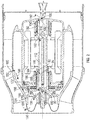
FIG. 1 is a sectional view of a first embodiment of a ventilation fan having an air bearing system; -
FIG. 2 is a sectional view of the first embodiment of the ventilation fan illustrating flow paths of the air bearing system; -
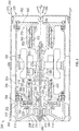
FIG. 3 is a sectional view of a second embodiment of a ventilation fan having an air bearing system; and -
FIG. 4 is a sectional view of the second embodiment of the ventilation fan illustrating flow paths of the air bearing system. - Referring now to the Figures, where the invention will be described with reference to specific embodiments, without limiting same, it is to be understood that the disclosed embodiments are merely illustrative and may be embodied in various and alternative forms. The Figures are not necessarily to scale; some features may be exaggerated or minimized to show details of particular components. Therefore, specific structural and functional details disclosed herein are not to be interpreted as limiting, but merely as a representative basis for teaching one skilled in the art to variously employ the present disclosure.
- Aircraft may include a cockpit or cabin ventilation system. The cockpit or cabin ventilation system may be provided as part of a larger environmental control system. The environment control system is configured to receive ambient air, condition the ambient air, and provide the conditioned air to various systems such as the cockpit or cabin ventilation system.
- Referring to
FIGS. 1 and2 , the conditioned air may be provided to the cockpit or cabin through aventilation fan 10. Theventilation fan 10 includes ahousing assembly 20, ashaft assembly 22, arotor 24, amotor housing 26, a bearinghousing 28, athrust plate 30, and anair bearing system 32. - The
housing assembly 20 includes afirst housing 40 that is operatively connected to asecond housing 42 and acheck valve assembly 44 that is operatively connected to thesecond housing 42. Thefirst housing 40 and thesecond housing 42 cooperate to define acavity 46 that may receive various components of theventilation fan 10. - The
first housing 40 defines a fan section inlet at afirst end 50 of thefirst housing 40 and a fan section outlet at asecond end 52 of thefirst housing 40. Thefirst end 50 may have a first diameter and thesecond end 52 may have a second diameter that is greater than the first diameter. - The
second housing 42 defines a rotor section inlet at afirst end 54 of thesecond housing 42 and a rotor section outlet at asecond end 56 of thesecond housing 42. Thefirst end 54 may have a first diameter and thesecond end 56 may have a second diameter that is substantially equal to the first diameter. Thefirst end 54 of thesecond housing 42 is operatively connected to thesecond end 52 of thefirst housing 40. - The
check valve assembly 44 is disposed proximate thesecond end 56 of thesecond housing 42. Thecheck valve assembly 44 includes a mountingframe 60, avalve plate 62, and avalve mechanism 64. The mountingframe 60 is disposed on an interior surface of thesecond housing 42. Thevalve plate 62 is operatively connected to thesecond housing 42 via the mountingframe 60. Thevalve plate 62 defines an opening that is configured to receive thevalve mechanism 64. Thevalve mechanism 64 is configured as a one-way valve to inhibit backflow through theventilation fan 10. - The
shaft assembly 22 is disposed within thecavity 46 of thehousing assembly 20. Theshaft assembly 22 extends along anaxis 70. The opening of thevalve plate 62 is disposed about theaxis 70. Theshaft assembly 22 includes afirst shaft 72, asecond shaft 74, and atie rod 76. In at least one embodiment, theshaft assembly 22 is configured as a one-piece shaft. - The
first shaft 72 is disposed within thefirst housing 40 and extends axially along theaxis 70. Thefirst shaft 72 extends at least partially into thesecond housing 42. Thefirst shaft 72 includes a first shaftfirst portion 80 and a first shaftsecond portion 82 that extends from the first shaftfirst portion 80. The first shaftfirst portion 80 is disposed proximate thefirst end 50 of thefirst housing 40. The first shaftfirst portion 80 defines afirst port 90. In at least one embodiment, thefirst port 90 is defined within a region that extends between the first shaftfirst portion 80 and the first shaftsecond portion 82. The first shaftsecond portion 82 extends towards thesecond end 52 of thefirst housing 40 along theaxis 70. The first shaftsecond portion 82 defines asecond port 92, afirst cavity 94, and athrust runner 96. Thefirst port 90 and thesecond port 92 extend into thefirst cavity 94. Thethrust runner 96 extends radially away from theaxis 70 and the first shaftsecond portion 82. - The
second shaft 74 is operatively connected to thefirst shaft 72. Thesecond shaft 74 is disposed within thesecond housing 42 and extends axially along theaxis 70. Thesecond shaft 74 includes a second shaftfirst portion 100 and a second shaft second portion 102. The second shaftfirst portion 100 is disposed proximate thefirst end 54 of thesecond housing 42. The second shaftfirst portion 100 is operatively connected to the first shaftsecond portion 82. The second shaftfirst portion 100 defines athird port 110 and asecond cavity 112. Thethird port 110 extends into thesecond cavity 112. The second shaft second portion 102 extends towards thesecond end 56 of thesecond housing 42 along theaxis 70. - The
tie rod 76 is operatively connected to thefirst shaft 72 and thesecond shaft 74. Thetie rod 76 is operatively connected to the first shaftfirst portion 80 and the second shaft second portion 102. Thetie rod 76 is disposed within and extends through thefirst cavity 94 and thesecond cavity 112. - The
rotor 24 is disposed within thefirst housing 40. Therotor 24 is rotatably connected to theshaft assembly 22 to define a rotative assembly. Therotor 24 includes a rotor first portion 120 and a rotorsecond portion 122. The rotor first portion 120 is disposed about the first shaftfirst portion 80. The rotor first portion 120 defines arotor port 124 that extends completely through the rotor first portion 120. The rotorsecond portion 122 extends from the rotor first portion 120 towards thesecond end 52 of thefirst housing 40. The rotorsecond portion 122 includes afan blade 126. Thefan blade 126 extends towards an inner surface of thefirst housing 40. - In at least one embodiment, the
rotor 24 includes ashroud 130. Theshroud 130 is operatively connected to the rotor first portion 120 and the first shaftfirst portion 80. Theshroud 130 defines at least one opening. - The
motor housing 26 is disposed within thecavity 46 and extends between thefirst housing 40 and thesecond housing 42 of thehousing assembly 20. Themotor housing 26 is configured to receive a motor that is configured to drive therotor 24 to rotate thefan blade 126. Themotor housing 26 is spaced apart from therotor 24. - The
motor housing 26 includes ahousing arm 140, ahousing leg 142, ahousing extension 144, and avane platform 146. Thehousing arm 140 is disposed about the first shaftsecond portion 82. Thehousing arm 140 is disposed substantially parallel to theaxis 70. Thehousing leg 142 extends from thehousing arm 140. Thehousing leg 142 is disposed substantially perpendicular to theaxis 70. Thehousing extension 144 extends from thehousing leg 142. Thehousing extension 144 is disposed substantially parallel to theaxis 70 and is disposed substantially parallel to thehousing arm 140. Thehousing extension 144 is radially spaced apart from thehousing arm 140. Thevane platform 146 extends from thehousing extension 144. At least a portion of thevane platform 146 is disposed substantially parallel to theaxis 70 and is disposed substantially parallel to thehousing extension 144 and thehousing arm 140. - The
vane platform 146 includes a stator or avane 150 that extends between thevane platform 146 and an inner surface of thesecond housing 42. Afirst opening 152 is defined between respective ends of the rotorsecond portion 122 and thevane platform 146. - The bearing
housing 28 is operatively connected to themotor housing 26. The bearinghousing 28 includes abearing arm 160, abearing leg 162, and abearing extension 164. Thebearing arm 160 is disposed about the second shaft second portion 102. Thebearing arm 160 is disposed substantially parallel to theaxis 70. Thebearing leg 162 extends from thebearing arm 160. Thebearing leg 162 is disposed substantially perpendicular to theaxis 70 and thebearing arm 160. At least a portion of thebearing leg 162 extends towards theaxis 70. Thebearing leg 162 of the bearinghousing 28 defines asecond opening 166. Thebearing extension 164 extends from thebearing leg 162 towards themotor housing 26. Thebearing extension 164 is operatively connected to at least one of thehousing extension 144 and thevane platform 146. Thebearing extension 164 is disposed substantially parallel to theaxis 70. - The
thrust plate 30 is positioned axially between therotor 24 and themotor housing 26. More specifically, thethrust plate 30 is positioned axially between the rotor first portion 120 and thehousing leg 142. Thethrust plate 30 is positioned radially between theshaft assembly 22 and therotor 24. More specifically, the thrust plate is positioned radially between the first shaftsecond portion 82 and the rotorsecond portion 122. Thethrust plate 30 defines athrust port 170 that extends into athird cavity 172 that is defined between thethrust plate 30 and thehousing leg 142 of themotor housing 26. - The
thrust runner 96 is at least partially received within thethird cavity 172. Thethrust runner 96 is positioned axially between thethrust plate 30 and thehousing leg 142 of themotor housing 26. In at least one embodiment, athrust air bearing 174 is disposed within thethird cavity 172. Thethrust air bearing 174 is disposed between thethrust runner 96 and at least one of thethrust plate 30 and thehousing leg 142 of themotor housing 26. - The
air bearing system 32 includes a first journal air bearing 180 and a secondjournal air bearing 182. The first journal air bearing 180 and the secondjournal air bearing 182 may be configured as thin-film hydrodynamic foil bearings that rotatably support rotating components of theventilation fan 10 such as theshaft assembly 22. - The first journal air bearing 180 is disposed about the first shaft
second portion 82. The first journal air bearing 180 is positioned radially between thehousing arm 140 and the first shaftsecond portion 82. The first journal air bearing 180 is positioned axially between thefirst port 90 and thesecond port 92. An inner surface of the first journal air bearing 180 and an outer surface of the first shaftsecond portion 82 define a first journal airbearing flow path 184. - The
first opening 152 is in fluid communication with thethrust port 170, thethird cavity 172, the first journal airbearing flow path 184, thesecond port 92, thefirst cavity 94, thefirst port 90, and therotor port 124 to define afirst flow path 186. Thefirst flow path 186 is illustrated by the solid block arrows shown inFIG. 2 . Airflow that flows through thefirst flow path 186 is exhausted through an opening of theshroud 130. - The second
journal air bearing 182 is disposed about the second shaft second portion 102. The secondjournal air bearing 182 is positioned radially between bearingarm 160 and the second shaft second portion 102. The secondjournal air bearing 182 is positioned axially between thethird port 110 and an end of the second shaft second portion 102. An inner surface of the secondjournal air bearing 182 and an outer surface of the second shaft second portion 102 define a second journal airbearing flow path 190. - The
second opening 166 is in fluid communication with the second journal airbearing flow path 190, thethird port 110, thesecond cavity 112, thefirst port 90, and therotor port 124 to define asecond flow path 192. Thesecond flow path 192 is illustrated by the dashed block arrows shown inFIG. 2 . Airflow that flows through thesecond flow path 192 is exhausted through the opening of theshroud 130. - Referring to
FIGS. 3 and4 , a second embodiment of aventilation fan 200 is illustrated. Theventilation fan 200 includes ahousing assembly 210, ashaft assembly 212, arotor 214, amotor housing 216, a bearinghousing 218, athrust plate 220, and anair bearing system 222. - The
housing assembly 210 includes ahousing body 230 and acheck valve assembly 232 that is operatively connected to thehousing body 230. Thehousing body 230 defines acavity 234 that may receive various components of theventilation fan 200. - The
housing body 230 defines a fan section inlet at afirst end 240 of thehousing body 230 and a fan section outlet at asecond end 242 of thehousing body 230. Thefirst end 240 may have a first diameter and thesecond end 242 may have a second diameter that is substantially equal to the first diameter. - The
check valve assembly 232 is disposed proximate thesecond end 242 of thehousing body 230. Thecheck valve assembly 232 includes a mountingframe 250, avalve plate 252, and avalve mechanism 254. The mountingframe 250 is disposed on an interior surface of thehousing body 230. Thevalve plate 252 is operatively connected to thehousing body 230 via the mountingframe 250. Thevalve plate 252 defines an opening that is configured to receive thevalve mechanism 254. Thevalve mechanism 254 is configured as a one-way valve to inhibit backflow through theventilation fan 200. - The
shaft assembly 212 is disposed within thecavity 234 of thehousing assembly 210. Theshaft assembly 212 extends along anaxis 260. The opening of thevalve plate 252 is disposed about theaxis 260. Theshaft assembly 212 includes a first shaft 270, asecond shaft 272, athird shaft 274, and atie rod 276. In at least one embodiment, theshaft assembly 212 is configured as a one-piece shaft. - The first shaft 270 extends axially along the
axis 260. The first shaft 270 includes a first shaftfirst portion 280 and a first shaftsecond portion 282 that extends from the first shaftfirst portion 280. The first shaftfirst portion 280 is disposed proximate thefirst end 240 of thehousing body 230. The first shaftsecond portion 282 extends towards thesecond end 242 of thehousing body 230 along theaxis 260. The first shaftsecond portion 282 defines afirst port 290, afirst cavity 292, and athrust runner 294. Thefirst port 290 extends into thefirst cavity 292. Thethrust runner 294 extends radially away from theaxis 260 and the first shaftsecond portion 282. - The
second shaft 272 is operatively connected to the first shaft 270. An end of thesecond shaft 272 is received within an end of the first shaft 270. Thesecond shaft 272 extends along theaxis 260. Thesecond shaft 272 defines asecond port 300 and asecond cavity 302. Thesecond port 300 is disposed proximate an end of the first shaft 270. Thesecond port 300 extends into thesecond cavity 302. - The
third shaft 274 is operatively connected to thesecond shaft 272. Thethird shaft 274 extends along theaxis 260. An end of thethird shaft 274 is disposed about an end of thesecond shaft 272. - The
tie rod 276 is operatively connected to the first shaft 270, thesecond shaft 272, and thethird shaft 274. Thetie rod 276 is operatively connected to the first shaftfirst portion 280 and thethird shaft 274. Thetie rod 276 is disposed within and extends through thefirst cavity 292 and thesecond cavity 302. - The
rotor 214 is disposed within thecavity 234 of thehousing body 230. Therotor 214 is rotatably connected to theshaft assembly 212 to define a rotative assembly. Therotor 214 includes a rotorfirst portion 310 and a rotorsecond portion 312. The rotorfirst portion 310 is disposed about the first shaftfirst portion 280. The rotorfirst portion 310 defines arotor port 314 that extends completely through the rotorfirst portion 310. The rotorsecond portion 312 extends from the rotorfirst portion 310 towards an inner surface of thehousing body 230. The rotorsecond portion 312 includes afan blade 316. Thefan blade 316 extends towards the inner surface of thehousing body 230. - The
motor housing 216 is disposed within thecavity 234 of thehousing assembly 20. Themotor housing 216 is configured to receive a motor that is configured to drive therotor 214 to rotate thefan blade 316. Themotor housing 216 is spaced apart from therotor 214. - The
motor housing 216 includes ahousing arm 320, ahousing leg 322, and avane platform 324. Thehousing arm 320 is disposed about the first shaftsecond portion 282. Thehousing arm 320 is disposed substantially parallel to theaxis 260. Thehousing leg 322 extends from thehousing arm 320. Thehousing leg 322 is disposed substantially perpendicular to theaxis 260. Thevane platform 324 extends from thehousing leg 322. At least a portion of thevane platform 324 is disposed substantially parallel to theaxis 260 and is disposed substantially parallel to thehousing arm 320. - The
vane platform 324 includes a stator or avane 330 that extends between thevane platform 324 and an inner surface of thehousing body 230. Ahousing port 332 is defined by thevane platform 324. Thehousing port 332 is defined by a portion of thevane platform 324 that extends towards the motor and theaxis 260. Afirst opening 334 is defined between respective ends of the rotorsecond portion 312 and at least one of thehousing leg 322 and thevane platform 324. - The bearing
housing 218 is operatively connected to themotor housing 216. The bearinghousing 218 includes abearing arm 340 and abearing leg 342. Thebearing arm 340 is disposed about thethird shaft 274. Thebearing arm 340 is disposed substantially parallel to theaxis 260. Thebearing leg 342 extends from thebearing arm 340. Thebearing leg 342 is disposed substantially perpendicular to theaxis 260 and thebearing arm 340. At least a portion of thebearing leg 342 extends towards theaxis 260. Thebearing leg 342 of the bearinghousing 218 defines asecond opening 344. Thebearing leg 342 is operatively connected to thevane platform 324. - The
thrust plate 220 is positioned axially between therotor 214 and themotor housing 216. More specifically, thethrust plate 220 is positioned axially between the rotorsecond portion 312 and thehousing leg 322. Thethrust plate 220 is positioned radially between theshaft assembly 212 andhousing body 230. Thethrust plate 220 defines athrust port 350 that extends into athird cavity 352 that is defined between thethrust plate 220 and thehousing leg 322 of themotor housing 216. In at least one embodiment, thefirst opening 334 is defined between respective ends of the rotorsecond portion 312 and thethrust plate 220. - The
thrust runner 294 is at least partially received within thethird cavity 352. Thethrust runner 294 is positioned axially between thethrust plate 220 and thehousing leg 322 of themotor housing 216. In at least one embodiment, athrust air bearing 354 is disposed within thethird cavity 352. Thethrust air bearing 354 is disposed between thethrust runner 294 and at least one of thethrust plate 220 and thehousing leg 322 of themotor housing 216. - The
air bearing system 222 includes a firstjournal air bearing 360 and a secondjournal air bearing 362. The firstjournal air bearing 360 and the secondjournal air bearing 362 may be configured as thin-film hydrodynamic foil bearings that are configured to rotatably support rotating components of theventilation fan 200 such as theshaft assembly 212. - The first
journal air bearing 360 is disposed about the first shaftsecond portion 282. The firstjournal air bearing 360 is positioned radially between thebearing arm 340 and the first shaftsecond portion 282. The firstjournal air bearing 360 is positioned axially between thefirst port 290 and thesecond port 300. An inner surface of the firstjournal air bearing 360 and an outer surface of the first shaftsecond portion 282 define a first journal airbearing flow path 364. - The
first opening 334 is in fluid communication with thethrust port 350, thethird cavity 352, the first journal airbearing flow path 364, thesecond port 300, thefirst cavity 292, thefirst port 290, and therotor port 314 to define afirst flow path 366. Thefirst flow path 366 is illustrated by the solid block arrows shown inFIG. 4 . - The second
journal air bearing 362 is disposed about thethird shaft 274. The secondjournal air bearing 362 is positioned radially between bearingarm 340 and thethird shaft 274. The secondjournal air bearing 362 is positioned axially between an end of thesecond shaft 272 and thebearing leg 342. An inner surface of the secondjournal air bearing 362 and an outer surface of thethird shaft 274 define a second journal airbearing flow path 370. - The
second opening 344 is in fluid communication with the second journal airbearing flow path 370, thehousing port 332, thesecond port 300, thefirst cavity 292, thefirst port 290, and therotor port 314 to define asecond flow path 372. Thesecond flow path 372 is illustrated by the dashed block arrows shown inFIG. 4 . - Throughout this specification, the term "attach," "attachment," "connected", "coupled," "coupling," "mount," or "mounting" shall be interpreted to mean that a structural component or element is in some manner connected to or contacts another element, either directly or indirectly through at least one intervening structural element, or is integrally formed with the other structural element.
- While the present disclosure has been described in detail in connection with only a limited number of embodiments, it should be readily understood that the present disclosure is not limited to such disclosed embodiments. Rather, the present disclosure can be modified to incorporate any number of variations, alterations, substitutions or equivalent arrangements not heretofore described, but which are commensurate with the scope of the present disclosure. Additionally, while various embodiments of the present disclosure have been described, it is to be understood that aspects of the present disclosure may include only some of the described embodiments or combinations of the described embodiments. Accordingly, the present disclosure is not to be seen as limited by the foregoing description, but is only limited by the scope of the appended claims.
Claims (11)
- A ventilation fan (10, 200), comprising:a shaft assembly (22, 212) extending along an axis and disposed within a housing assembly (20, 210), the shaft assembly (22, 212) including a first shaft (72, 270) having a first shaft first portion (80, 280), defining a first port (90, 290), and a first shaft second portion (82, 282), defining a second port (92, 300), operatively connected to a second shaft (272, 74) having a second shaft first portion (100), defining a third port, and a second shaft second portion (102);a rotor (24, 214) having a rotor first portion (120, 310) disposed about the first shaft first portion (80, 280) and a rotor second portion (122, 312) extending from the rotor first portion (120, 310), the rotor first portion (120, 310) defining a rotor port (124,314);a motor housing (26, 216) disposed about the first shaft second portion (82, 282), the motor housing (26, 216) having a housing arm (140, 320), a housing leg (142, 322) extending from the housing arm (140, 320), a housing extension (144) extending from the housing leg (142, 322), and a vane platform (146) extending from the housing extension (144);a first opening (152) being defined between respective ends of the rotor second portion (122) and the vane platform (146); anda bearing housing (28, 218) operatively connected to the motor housing (26, 216) and disposed about the second shaft second portion (102), the bearing housing (26, 216) having a bearing arm (160, 340), a bearing leg (162, 342) extending from the bearing arm (160, 340), and a bearing extension (164) extending from the bearing leg.
- The ventilation fan of claim 1, further comprising:a first journal air bearing (180, 360) that rotatably supports the shaft assembly (22, 212), the first journal air bearing being positioned radially between the housing arm (140, 320) and the first shaft second portion (82, 282) and positioned axially between the first port (90, 290) and the second port (92, 300).
- The ventilation fan of claim 2, wherein an inner surface of the first journal air bearing (180, 360) and an outer surface of the first shaft second portion (82, 282) define a first journal air bearing flow path.
- The ventilation fan of claim 3, further comprising:a thrust plate (30, 220) positioned radially between the first shaft second (82, 282) portion and the rotor second portion (122, 312) and positioned axially between the rotor first portion (120, 310) and the housing leg (142, 322);a thrust runner (96, 294) positioned axially between the thrust plate (30, 220) and the housing leg (142, 322); anda thrust air bearing (174, 354) disposed between the thrust runner (96, 294) and at least one of the thrust plate (30, 220) and the housing leg (142, 322).
- The ventilation fan of claim 4, wherein the first shaft second portion (82, 282) defines a thrust runner (96, 294) positioned axially between the thrust plate (30, 220) and the housing leg (142, 322).
- The ventilation fan of claim 5, wherein the thrust plate (30, 220) defines a thrust port (170, 350).
- The ventilation fan of claim 6, wherein the first opening (152) is in fluid communication with the thrust port (170, 350), the first journal air bearing flow path, the second port, the first port, and the rotor port to define a first flow path.
- The ventilation fan of any preceding claim, further comprising:a second journal air bearing (182, 362) positioned radially between the bearing arm and the second shaft second portion (102).
- The ventilation fan of claim 8, wherein an inner surface of the second journal air bearing (182, 362) and an outer surface of the second shaft second portion (102) define a second journal air bearing flow path (370).
- The ventilation fan of claim 9, wherein the bearing housing (28, 218) defines a second opening (166, 344).
- The ventilation fan of claim 10, wherein the second opening (166, 344) is in fluid communication with the second journal air bearing flow path (370) and the third port to define a second flow path.
Applications Claiming Priority (1)
| Application Number | Priority Date | Filing Date | Title |
|---|---|---|---|
| US15/255,488 US10371156B2 (en) | 2016-09-02 | 2016-09-02 | Ventilation fan having air bearing system |
Publications (2)
| Publication Number | Publication Date |
|---|---|
| EP3290714A1 true EP3290714A1 (en) | 2018-03-07 |
| EP3290714B1 EP3290714B1 (en) | 2021-04-28 |
Family
ID=59761779
Family Applications (1)
| Application Number | Title | Priority Date | Filing Date |
|---|---|---|---|
| EP17188731.8A Active EP3290714B1 (en) | 2016-09-02 | 2017-08-31 | Ventilation fan having air bearing system |
Country Status (2)
| Country | Link |
|---|---|
| US (1) | US10371156B2 (en) |
| EP (1) | EP3290714B1 (en) |
Cited By (3)
| Publication number | Priority date | Publication date | Assignee | Title |
|---|---|---|---|---|
| EP3539877A1 (en) * | 2018-03-16 | 2019-09-18 | Hamilton Sundstrand Corporation | Housing for a ram air fan motor |
| EP3550149A1 (en) * | 2018-04-03 | 2019-10-09 | Hamilton Sundstrand Corporation | Structurally improved ram fan inlet shroud |
| EP3754817A1 (en) * | 2019-06-21 | 2020-12-23 | LG Electronics Inc. | Motor assembly and method for manufacturing the same |
Families Citing this family (20)
| Publication number | Priority date | Publication date | Assignee | Title |
|---|---|---|---|---|
| US10876539B2 (en) | 2016-09-07 | 2020-12-29 | Hamilton Sunstrand Corporation | Ventilation fan having a hybrid bearing system |
| KR101896173B1 (en) * | 2017-02-01 | 2018-09-07 | 엘지전자 주식회사 | Fan Motor |
| CN110030113B (en) * | 2019-05-27 | 2024-04-16 | 宁波志胜空天动力科技有限公司 | Supercharged ramjet engine and aircraft |
| CN110185637A (en) * | 2019-06-03 | 2019-08-30 | 深圳国氢新能源科技有限公司 | Fuel cell compressor |
| US11668324B2 (en) * | 2019-08-02 | 2023-06-06 | Hamilton Sundstrand Corporation | Motor and bearing cooling paths and a transfer tube for another cooling channel |
| US11225978B2 (en) | 2019-08-02 | 2022-01-18 | Hamilton Sundstrand Corporation | Motor and bearing cooling paths |
| US11261880B2 (en) * | 2019-08-02 | 2022-03-01 | Hamilton Sundstrand Corporation | Motor and bearing cooling paths |
| US11143203B2 (en) * | 2019-08-02 | 2021-10-12 | Hamilton Sundstrand Corporation | Motor and bearing cooling paths |
| JP7523087B2 (en) * | 2020-02-20 | 2024-07-26 | パナソニックIpマネジメント株式会社 | Bearing structure |
| CN112901527B (en) * | 2021-02-04 | 2022-11-29 | 广东智空动力科技有限公司 | air bearing compressor |
| FR3127031B1 (en) * | 2021-09-10 | 2025-04-04 | Safran Ventilation Systems | ELECTRIC FAN FOR AIRCRAFT |
| US12448978B2 (en) | 2022-05-03 | 2025-10-21 | General Electric Company | Layered barrier cans for pumps and methods of producing the same |
| US12345279B2 (en) | 2022-05-03 | 2025-07-01 | General Electric Company | Oil lubricated fluid pumps with oil separators |
| US12421968B2 (en) | 2022-05-03 | 2025-09-23 | General Electric Company | Axial flux motor driven pump systems for pressurizing fluid in closed loop systems |
| US12460647B2 (en) | 2022-05-03 | 2025-11-04 | General Electric Company | Integrated bearing systems for dynamically supporting shafts in pump systems |
| US12601352B2 (en) | 2022-05-03 | 2026-04-14 | General Electric Company | High pressure magnetic coupling shrouds and methods of producing the same |
| CN115065196B (en) * | 2022-07-25 | 2023-06-23 | 浙江卓瑞机电有限公司 | Noise-proof frame and noise-proof motor in motor |
| US12331781B2 (en) | 2023-02-03 | 2025-06-17 | General Electric Company | Dual thrust bearing systems and methods for operating the same |
| US20250347233A1 (en) * | 2024-05-13 | 2025-11-13 | Hamilton Sundstrand Corporation | Hydrodynamic foil bearing shaft |
| US20250347448A1 (en) * | 2024-05-13 | 2025-11-13 | Hamilton Sundstrand Corporation | Unidirectional thrust air cycle machine arrangement with asymmetric thrust bearings |
Citations (3)
| Publication number | Priority date | Publication date | Assignee | Title |
|---|---|---|---|---|
| US20060061222A1 (en) * | 2004-09-22 | 2006-03-23 | Hamilton Sundstrand | Air bearing and motor cooling |
| US20060061221A1 (en) * | 2004-09-22 | 2006-03-23 | Mcauliffe Christopher | Integral motor and air bearing cooling path |
| US20130101436A1 (en) * | 2011-10-24 | 2013-04-25 | Hamilton Sundstrand Corporation | Fan rotor with cooling holes |
Family Cites Families (24)
| Publication number | Priority date | Publication date | Assignee | Title |
|---|---|---|---|---|
| US4507939A (en) * | 1983-12-16 | 1985-04-02 | The Garrett Corporation | Three wheel center fan cooling turbine apparatus and associated methods |
| US5113670A (en) * | 1990-08-03 | 1992-05-19 | United Technologies Corporation | Bearing cooling arrangement for air cycle machine |
| US6151909A (en) * | 1998-03-13 | 2000-11-28 | Alliedsignal Inc. | Two spool air cycle machine having concentric shafts |
| WO2006017063A2 (en) * | 2004-07-07 | 2006-02-16 | Disney Enterprises, Inc. | Process control oxidation |
| US8347647B2 (en) * | 2004-09-22 | 2013-01-08 | Hamilton Sundstrand Corporation | Air cycle machine for an aircraft environmental control system |
| US7757502B2 (en) * | 2004-09-22 | 2010-07-20 | Hamilton Sundstrand Corporation | RAM fan system for an aircraft environmental control system |
| US7402020B2 (en) * | 2005-12-14 | 2008-07-22 | Hamilton Sundstrand Corporation | ACM cooling flow path and thrust load design |
| US8496533B2 (en) * | 2010-03-22 | 2013-07-30 | Hamilton Sundstrand Corporation | Journal bearing with dual pass cooling for air machine |
| JP4932921B2 (en) * | 2010-03-31 | 2012-05-16 | 本田技研工業株式会社 | Electric centrifugal compressor |
| US8814499B2 (en) * | 2010-04-19 | 2014-08-26 | Korea Fluid Machinery Co., Ltd. | Centrifugal compressor |
| US8459966B2 (en) * | 2010-07-19 | 2013-06-11 | Hamilton Sundstrand Corporation | Ram air fan motor cooling |
| US8529192B2 (en) * | 2010-09-15 | 2013-09-10 | Hamilton Sundstrand Corporation | Thrust bearing shaft for thrust and journal air bearing cooling in a compressor |
| US8622620B2 (en) * | 2010-09-15 | 2014-01-07 | Hamilton Sundstrand Corporation | Shaft for air bearing and motor cooling in compressor |
| US8905707B2 (en) * | 2010-12-21 | 2014-12-09 | Hamilton Sundstrand Corporation | Bearing cooling control in an air cycle machine |
| US8784048B2 (en) * | 2010-12-21 | 2014-07-22 | Hamilton Sundstrand Corporation | Air cycle machine bearing cooling inlet plate |
| US20130010143A1 (en) * | 2011-07-06 | 2013-01-10 | Mike's Inc. | Imaging assembly for marine use |
| US9062712B1 (en) | 2012-02-27 | 2015-06-23 | The United States Of America As Represented By The Administrator Of The National Aeronautics And Space Administration | Passive thermal management of foil bearings |
| US8672768B2 (en) * | 2012-04-11 | 2014-03-18 | Hamilton Sundstrand Corporation | Air bearing shaft for ram air fan |
| US8734017B1 (en) * | 2013-03-08 | 2014-05-27 | Hamilton Sundstrand Corporation | Air bearing shaft |
| US9638199B2 (en) * | 2013-04-26 | 2017-05-02 | Hamilton Sundstrand Corporation | Ram air fan inlet shroud |
| US20150037138A1 (en) | 2013-07-30 | 2015-02-05 | Hamilton Sundstrand Corporation | Thrust shaft for ram air fan |
| US9914542B2 (en) | 2013-10-14 | 2018-03-13 | Hamilton Sundstrand Corporation | Ram air fan housing |
| US9759236B2 (en) | 2014-04-25 | 2017-09-12 | Hamilton Sundstrand Corporation | Inlet tube design |
| US10584706B2 (en) * | 2015-01-16 | 2020-03-10 | Hamilton Sundstrand Corporation | Ram fan device and motor cooling systems and methods |
-
2016
- 2016-09-02 US US15/255,488 patent/US10371156B2/en active Active
-
2017
- 2017-08-31 EP EP17188731.8A patent/EP3290714B1/en active Active
Patent Citations (3)
| Publication number | Priority date | Publication date | Assignee | Title |
|---|---|---|---|---|
| US20060061222A1 (en) * | 2004-09-22 | 2006-03-23 | Hamilton Sundstrand | Air bearing and motor cooling |
| US20060061221A1 (en) * | 2004-09-22 | 2006-03-23 | Mcauliffe Christopher | Integral motor and air bearing cooling path |
| US20130101436A1 (en) * | 2011-10-24 | 2013-04-25 | Hamilton Sundstrand Corporation | Fan rotor with cooling holes |
Cited By (6)
| Publication number | Priority date | Publication date | Assignee | Title |
|---|---|---|---|---|
| EP3539877A1 (en) * | 2018-03-16 | 2019-09-18 | Hamilton Sundstrand Corporation | Housing for a ram air fan motor |
| US10774843B2 (en) | 2018-03-16 | 2020-09-15 | Hamilton Sundstrand Corporation | Fan housing for ram air fan |
| EP3550149A1 (en) * | 2018-04-03 | 2019-10-09 | Hamilton Sundstrand Corporation | Structurally improved ram fan inlet shroud |
| US10829241B2 (en) | 2018-04-03 | 2020-11-10 | Hamilton Sunstrand Corporation | Structurally improved ram fan inlet shroud |
| EP3754817A1 (en) * | 2019-06-21 | 2020-12-23 | LG Electronics Inc. | Motor assembly and method for manufacturing the same |
| US11466695B2 (en) | 2019-06-21 | 2022-10-11 | Lg Electronics Inc. | Motor assembly and method for manufacturing the same |
Also Published As
| Publication number | Publication date |
|---|---|
| US10371156B2 (en) | 2019-08-06 |
| US20180066666A1 (en) | 2018-03-08 |
| EP3290714B1 (en) | 2021-04-28 |
Similar Documents
| Publication | Publication Date | Title |
|---|---|---|
| EP3290714B1 (en) | Ventilation fan having air bearing system | |
| US12000405B2 (en) | Ventilation fan having a hybrid bearing system | |
| EP2711296B1 (en) | Cooling arrangement for a motor assembly and method of cooling a motor assembly | |
| US11226114B2 (en) | Inlet for axial fan | |
| JP4935048B2 (en) | Centrifugal fan | |
| DE202012013669U1 (en) | Active cooling of a motor with integrated cooling channel | |
| CN103062132B (en) | Ram-air fan diffuser | |
| CN108350932B (en) | Bearing structure and supercharger | |
| EP3553275A1 (en) | Compressor or turbine with back-disk seal and vent | |
| US20120171016A1 (en) | Ram air turbine inlet | |
| US20190101129A1 (en) | Electric blower and electric vacuum cleaner equipped with same | |
| JP4935051B2 (en) | Centrifugal fan | |
| EP3320215B1 (en) | Compact axial fan | |
| JP2007040299A (en) | Passive fan assembly | |
| EP3550149B1 (en) | Structurally improved ram fan inlet shroud | |
| JPH05288195A (en) | Electric blower | |
| US20140044524A1 (en) | Impeller fan assembly | |
| US20220170474A1 (en) | Pump device comprising a radial bearing | |
| CN109736901B (en) | Bearing casing and auxiliary power device | |
| JP6297467B2 (en) | Centrifugal fan | |
| EP2894349A1 (en) | Fan assembly for air-ventilation-device of traction-motor | |
| CN206180777U (en) | Many rotors motor | |
| CN116538099B (en) | Delivery device for delivering liquid | |
| KR200355838Y1 (en) | Cross flow type fan motor | |
| KR100512032B1 (en) | Axial fan assembly |
Legal Events
| Date | Code | Title | Description |
|---|---|---|---|
| PUAI | Public reference made under article 153(3) epc to a published international application that has entered the european phase |
Free format text: ORIGINAL CODE: 0009012 |
|
| STAA | Information on the status of an ep patent application or granted ep patent |
Free format text: STATUS: THE APPLICATION HAS BEEN PUBLISHED |
|
| AK | Designated contracting states |
Kind code of ref document: A1 Designated state(s): AL AT BE BG CH CY CZ DE DK EE ES FI FR GB GR HR HU IE IS IT LI LT LU LV MC MK MT NL NO PL PT RO RS SE SI SK SM TR |
|
| AX | Request for extension of the european patent |
Extension state: BA ME |
|
| STAA | Information on the status of an ep patent application or granted ep patent |
Free format text: STATUS: REQUEST FOR EXAMINATION WAS MADE |
|
| 17P | Request for examination filed |
Effective date: 20180906 |
|
| RBV | Designated contracting states (corrected) |
Designated state(s): AL AT BE BG CH CY CZ DE DK EE ES FI FR GB GR HR HU IE IS IT LI LT LU LV MC MK MT NL NO PL PT RO RS SE SI SK SM TR |
|
| STAA | Information on the status of an ep patent application or granted ep patent |
Free format text: STATUS: EXAMINATION IS IN PROGRESS |
|
| 17Q | First examination report despatched |
Effective date: 20200414 |
|
| GRAP | Despatch of communication of intention to grant a patent |
Free format text: ORIGINAL CODE: EPIDOSNIGR1 |
|
| STAA | Information on the status of an ep patent application or granted ep patent |
Free format text: STATUS: GRANT OF PATENT IS INTENDED |
|
| INTG | Intention to grant announced |
Effective date: 20201117 |
|
| RAP1 | Party data changed (applicant data changed or rights of an application transferred) |
Owner name: HAMILTON SUNDSTRAND CORPORATION |
|
| GRAS | Grant fee paid |
Free format text: ORIGINAL CODE: EPIDOSNIGR3 |
|
| GRAA | (expected) grant |
Free format text: ORIGINAL CODE: 0009210 |
|
| STAA | Information on the status of an ep patent application or granted ep patent |
Free format text: STATUS: THE PATENT HAS BEEN GRANTED |
|
| AK | Designated contracting states |
Kind code of ref document: B1 Designated state(s): AL AT BE BG CH CY CZ DE DK EE ES FI FR GB GR HR HU IE IS IT LI LT LU LV MC MK MT NL NO PL PT RO RS SE SI SK SM TR |
|
| REG | Reference to a national code |
Ref country code: GB Ref legal event code: FG4D |
|
| REG | Reference to a national code |
Ref country code: CH Ref legal event code: EP |
|
| REG | Reference to a national code |
Ref country code: AT Ref legal event code: REF Ref document number: 1387365 Country of ref document: AT Kind code of ref document: T Effective date: 20210515 |
|
| REG | Reference to a national code |
Ref country code: DE Ref legal event code: R096 Ref document number: 602017037476 Country of ref document: DE |
|
| REG | Reference to a national code |
Ref country code: IE Ref legal event code: FG4D |
|
| REG | Reference to a national code |
Ref country code: LT Ref legal event code: MG9D |
|
| REG | Reference to a national code |
Ref country code: AT Ref legal event code: MK05 Ref document number: 1387365 Country of ref document: AT Kind code of ref document: T Effective date: 20210428 |
|
| PG25 | Lapsed in a contracting state [announced via postgrant information from national office to epo] |
Ref country code: NL Free format text: LAPSE BECAUSE OF FAILURE TO SUBMIT A TRANSLATION OF THE DESCRIPTION OR TO PAY THE FEE WITHIN THE PRESCRIBED TIME-LIMIT Effective date: 20210428 Ref country code: HR Free format text: LAPSE BECAUSE OF FAILURE TO SUBMIT A TRANSLATION OF THE DESCRIPTION OR TO PAY THE FEE WITHIN THE PRESCRIBED TIME-LIMIT Effective date: 20210428 Ref country code: BG Free format text: LAPSE BECAUSE OF FAILURE TO SUBMIT A TRANSLATION OF THE DESCRIPTION OR TO PAY THE FEE WITHIN THE PRESCRIBED TIME-LIMIT Effective date: 20210728 Ref country code: AT Free format text: LAPSE BECAUSE OF FAILURE TO SUBMIT A TRANSLATION OF THE DESCRIPTION OR TO PAY THE FEE WITHIN THE PRESCRIBED TIME-LIMIT Effective date: 20210428 Ref country code: FI Free format text: LAPSE BECAUSE OF FAILURE TO SUBMIT A TRANSLATION OF THE DESCRIPTION OR TO PAY THE FEE WITHIN THE PRESCRIBED TIME-LIMIT Effective date: 20210428 Ref country code: LT Free format text: LAPSE BECAUSE OF FAILURE TO SUBMIT A TRANSLATION OF THE DESCRIPTION OR TO PAY THE FEE WITHIN THE PRESCRIBED TIME-LIMIT Effective date: 20210428 |
|
| PG25 | Lapsed in a contracting state [announced via postgrant information from national office to epo] |
Ref country code: GR Free format text: LAPSE BECAUSE OF FAILURE TO SUBMIT A TRANSLATION OF THE DESCRIPTION OR TO PAY THE FEE WITHIN THE PRESCRIBED TIME-LIMIT Effective date: 20210729 Ref country code: LV Free format text: LAPSE BECAUSE OF FAILURE TO SUBMIT A TRANSLATION OF THE DESCRIPTION OR TO PAY THE FEE WITHIN THE PRESCRIBED TIME-LIMIT Effective date: 20210428 Ref country code: IS Free format text: LAPSE BECAUSE OF FAILURE TO SUBMIT A TRANSLATION OF THE DESCRIPTION OR TO PAY THE FEE WITHIN THE PRESCRIBED TIME-LIMIT Effective date: 20210828 Ref country code: PL Free format text: LAPSE BECAUSE OF FAILURE TO SUBMIT A TRANSLATION OF THE DESCRIPTION OR TO PAY THE FEE WITHIN THE PRESCRIBED TIME-LIMIT Effective date: 20210428 Ref country code: NO Free format text: LAPSE BECAUSE OF FAILURE TO SUBMIT A TRANSLATION OF THE DESCRIPTION OR TO PAY THE FEE WITHIN THE PRESCRIBED TIME-LIMIT Effective date: 20210728 Ref country code: PT Free format text: LAPSE BECAUSE OF FAILURE TO SUBMIT A TRANSLATION OF THE DESCRIPTION OR TO PAY THE FEE WITHIN THE PRESCRIBED TIME-LIMIT Effective date: 20210830 Ref country code: SE Free format text: LAPSE BECAUSE OF FAILURE TO SUBMIT A TRANSLATION OF THE DESCRIPTION OR TO PAY THE FEE WITHIN THE PRESCRIBED TIME-LIMIT Effective date: 20210428 Ref country code: RS Free format text: LAPSE BECAUSE OF FAILURE TO SUBMIT A TRANSLATION OF THE DESCRIPTION OR TO PAY THE FEE WITHIN THE PRESCRIBED TIME-LIMIT Effective date: 20210428 |
|
| REG | Reference to a national code |
Ref country code: NL Ref legal event code: MP Effective date: 20210428 |
|
| PG25 | Lapsed in a contracting state [announced via postgrant information from national office to epo] |
Ref country code: SM Free format text: LAPSE BECAUSE OF FAILURE TO SUBMIT A TRANSLATION OF THE DESCRIPTION OR TO PAY THE FEE WITHIN THE PRESCRIBED TIME-LIMIT Effective date: 20210428 Ref country code: SK Free format text: LAPSE BECAUSE OF FAILURE TO SUBMIT A TRANSLATION OF THE DESCRIPTION OR TO PAY THE FEE WITHIN THE PRESCRIBED TIME-LIMIT Effective date: 20210428 Ref country code: RO Free format text: LAPSE BECAUSE OF FAILURE TO SUBMIT A TRANSLATION OF THE DESCRIPTION OR TO PAY THE FEE WITHIN THE PRESCRIBED TIME-LIMIT Effective date: 20210428 Ref country code: ES Free format text: LAPSE BECAUSE OF FAILURE TO SUBMIT A TRANSLATION OF THE DESCRIPTION OR TO PAY THE FEE WITHIN THE PRESCRIBED TIME-LIMIT Effective date: 20210428 Ref country code: EE Free format text: LAPSE BECAUSE OF FAILURE TO SUBMIT A TRANSLATION OF THE DESCRIPTION OR TO PAY THE FEE WITHIN THE PRESCRIBED TIME-LIMIT Effective date: 20210428 Ref country code: CZ Free format text: LAPSE BECAUSE OF FAILURE TO SUBMIT A TRANSLATION OF THE DESCRIPTION OR TO PAY THE FEE WITHIN THE PRESCRIBED TIME-LIMIT Effective date: 20210428 Ref country code: DK Free format text: LAPSE BECAUSE OF FAILURE TO SUBMIT A TRANSLATION OF THE DESCRIPTION OR TO PAY THE FEE WITHIN THE PRESCRIBED TIME-LIMIT Effective date: 20210428 |
|
| REG | Reference to a national code |
Ref country code: DE Ref legal event code: R097 Ref document number: 602017037476 Country of ref document: DE |
|
| PLBE | No opposition filed within time limit |
Free format text: ORIGINAL CODE: 0009261 |
|
| STAA | Information on the status of an ep patent application or granted ep patent |
Free format text: STATUS: NO OPPOSITION FILED WITHIN TIME LIMIT |
|
| REG | Reference to a national code |
Ref country code: CH Ref legal event code: PL |
|
| PG25 | Lapsed in a contracting state [announced via postgrant information from national office to epo] |
Ref country code: MC Free format text: LAPSE BECAUSE OF FAILURE TO SUBMIT A TRANSLATION OF THE DESCRIPTION OR TO PAY THE FEE WITHIN THE PRESCRIBED TIME-LIMIT Effective date: 20210428 |
|
| 26N | No opposition filed |
Effective date: 20220131 |
|
| REG | Reference to a national code |
Ref country code: BE Ref legal event code: MM Effective date: 20210831 |
|
| PG25 | Lapsed in a contracting state [announced via postgrant information from national office to epo] |
Ref country code: LI Free format text: LAPSE BECAUSE OF NON-PAYMENT OF DUE FEES Effective date: 20210831 Ref country code: CH Free format text: LAPSE BECAUSE OF NON-PAYMENT OF DUE FEES Effective date: 20210831 |
|
| PG25 | Lapsed in a contracting state [announced via postgrant information from national office to epo] |
Ref country code: IS Free format text: LAPSE BECAUSE OF FAILURE TO SUBMIT A TRANSLATION OF THE DESCRIPTION OR TO PAY THE FEE WITHIN THE PRESCRIBED TIME-LIMIT Effective date: 20210828 Ref country code: LU Free format text: LAPSE BECAUSE OF NON-PAYMENT OF DUE FEES Effective date: 20210831 Ref country code: AL Free format text: LAPSE BECAUSE OF FAILURE TO SUBMIT A TRANSLATION OF THE DESCRIPTION OR TO PAY THE FEE WITHIN THE PRESCRIBED TIME-LIMIT Effective date: 20210428 |
|
| PG25 | Lapsed in a contracting state [announced via postgrant information from national office to epo] |
Ref country code: IT Free format text: LAPSE BECAUSE OF FAILURE TO SUBMIT A TRANSLATION OF THE DESCRIPTION OR TO PAY THE FEE WITHIN THE PRESCRIBED TIME-LIMIT Effective date: 20210428 Ref country code: IE Free format text: LAPSE BECAUSE OF NON-PAYMENT OF DUE FEES Effective date: 20210831 Ref country code: BE Free format text: LAPSE BECAUSE OF NON-PAYMENT OF DUE FEES Effective date: 20210831 |
|
| PG25 | Lapsed in a contracting state [announced via postgrant information from national office to epo] |
Ref country code: HU Free format text: LAPSE BECAUSE OF FAILURE TO SUBMIT A TRANSLATION OF THE DESCRIPTION OR TO PAY THE FEE WITHIN THE PRESCRIBED TIME-LIMIT; INVALID AB INITIO Effective date: 20170831 |
|
| P01 | Opt-out of the competence of the unified patent court (upc) registered |
Effective date: 20230522 |
|
| PG25 | Lapsed in a contracting state [announced via postgrant information from national office to epo] |
Ref country code: CY Free format text: LAPSE BECAUSE OF FAILURE TO SUBMIT A TRANSLATION OF THE DESCRIPTION OR TO PAY THE FEE WITHIN THE PRESCRIBED TIME-LIMIT Effective date: 20210428 |
|
| PG25 | Lapsed in a contracting state [announced via postgrant information from national office to epo] |
Ref country code: MK Free format text: LAPSE BECAUSE OF FAILURE TO SUBMIT A TRANSLATION OF THE DESCRIPTION OR TO PAY THE FEE WITHIN THE PRESCRIBED TIME-LIMIT Effective date: 20210428 |
|
| PG25 | Lapsed in a contracting state [announced via postgrant information from national office to epo] |
Ref country code: TR Free format text: LAPSE BECAUSE OF FAILURE TO SUBMIT A TRANSLATION OF THE DESCRIPTION OR TO PAY THE FEE WITHIN THE PRESCRIBED TIME-LIMIT Effective date: 20210428 |
|
| PG25 | Lapsed in a contracting state [announced via postgrant information from national office to epo] |
Ref country code: MT Free format text: LAPSE BECAUSE OF FAILURE TO SUBMIT A TRANSLATION OF THE DESCRIPTION OR TO PAY THE FEE WITHIN THE PRESCRIBED TIME-LIMIT Effective date: 20210428 |
|
| PGFP | Annual fee paid to national office [announced via postgrant information from national office to epo] |
Ref country code: DE Payment date: 20250724 Year of fee payment: 9 |
|
| PGFP | Annual fee paid to national office [announced via postgrant information from national office to epo] |
Ref country code: GB Payment date: 20250724 Year of fee payment: 9 |
|
| PGFP | Annual fee paid to national office [announced via postgrant information from national office to epo] |
Ref country code: FR Payment date: 20250725 Year of fee payment: 9 |