EP3290640A1 - Retaining assembly with tabs and retaining ring - Google Patents
Retaining assembly with tabs and retaining ring Download PDFInfo
- Publication number
- EP3290640A1 EP3290640A1 EP17188824.1A EP17188824A EP3290640A1 EP 3290640 A1 EP3290640 A1 EP 3290640A1 EP 17188824 A EP17188824 A EP 17188824A EP 3290640 A1 EP3290640 A1 EP 3290640A1
- Authority
- EP
- European Patent Office
- Prior art keywords
- housing
- circumferential slot
- component
- retaining ring
- tabs
- Prior art date
- Legal status (The legal status is an assumption and is not a legal conclusion. Google has not performed a legal analysis and makes no representation as to the accuracy of the status listed.)
- Granted
Links
Images

Classifications
-
- F—MECHANICAL ENGINEERING; LIGHTING; HEATING; WEAPONS; BLASTING
- F01—MACHINES OR ENGINES IN GENERAL; ENGINE PLANTS IN GENERAL; STEAM ENGINES
- F01D—NON-POSITIVE DISPLACEMENT MACHINES OR ENGINES, e.g. STEAM TURBINES
- F01D5/00—Blades; Blade-carrying members; Heating, heat-insulating, cooling or antivibration means on the blades or the members
- F01D5/30—Fixing blades to rotors; Blade roots ; Blade spacers
-
- F—MECHANICAL ENGINEERING; LIGHTING; HEATING; WEAPONS; BLASTING
- F01—MACHINES OR ENGINES IN GENERAL; ENGINE PLANTS IN GENERAL; STEAM ENGINES
- F01D—NON-POSITIVE DISPLACEMENT MACHINES OR ENGINES, e.g. STEAM TURBINES
- F01D5/00—Blades; Blade-carrying members; Heating, heat-insulating, cooling or antivibration means on the blades or the members
- F01D5/30—Fixing blades to rotors; Blade roots ; Blade spacers
- F01D5/3007—Fixing blades to rotors; Blade roots ; Blade spacers of axial insertion type
-
- F—MECHANICAL ENGINEERING; LIGHTING; HEATING; WEAPONS; BLASTING
- F01—MACHINES OR ENGINES IN GENERAL; ENGINE PLANTS IN GENERAL; STEAM ENGINES
- F01D—NON-POSITIVE DISPLACEMENT MACHINES OR ENGINES, e.g. STEAM TURBINES
- F01D5/00—Blades; Blade-carrying members; Heating, heat-insulating, cooling or antivibration means on the blades or the members
- F01D5/30—Fixing blades to rotors; Blade roots ; Blade spacers
- F01D5/3007—Fixing blades to rotors; Blade roots ; Blade spacers of axial insertion type
- F01D5/3015—Fixing blades to rotors; Blade roots ; Blade spacers of axial insertion type with side plates
-
- F—MECHANICAL ENGINEERING; LIGHTING; HEATING; WEAPONS; BLASTING
- F01—MACHINES OR ENGINES IN GENERAL; ENGINE PLANTS IN GENERAL; STEAM ENGINES
- F01D—NON-POSITIVE DISPLACEMENT MACHINES OR ENGINES, e.g. STEAM TURBINES
- F01D5/00—Blades; Blade-carrying members; Heating, heat-insulating, cooling or antivibration means on the blades or the members
- F01D5/34—Rotor-blade aggregates of unitary construction, e.g. formed of sheet laminae
-
- F—MECHANICAL ENGINEERING; LIGHTING; HEATING; WEAPONS; BLASTING
- F01—MACHINES OR ENGINES IN GENERAL; ENGINE PLANTS IN GENERAL; STEAM ENGINES
- F01D—NON-POSITIVE DISPLACEMENT MACHINES OR ENGINES, e.g. STEAM TURBINES
- F01D9/00—Stators
- F01D9/02—Nozzles; Nozzle boxes; Stator blades; Guide conduits, e.g. individual nozzles
- F01D9/04—Nozzles; Nozzle boxes; Stator blades; Guide conduits, e.g. individual nozzles forming ring or sector
- F01D9/042—Nozzles; Nozzle boxes; Stator blades; Guide conduits, e.g. individual nozzles forming ring or sector fixing blades to stators
-
- F—MECHANICAL ENGINEERING; LIGHTING; HEATING; WEAPONS; BLASTING
- F05—INDEXING SCHEMES RELATING TO ENGINES OR PUMPS IN VARIOUS SUBCLASSES OF CLASSES F01-F04
- F05D—INDEXING SCHEME FOR ASPECTS RELATING TO NON-POSITIVE-DISPLACEMENT MACHINES OR ENGINES, GAS-TURBINES OR JET-PROPULSION PLANTS
- F05D2220/00—Application
- F05D2220/30—Application in turbines
- F05D2220/32—Application in turbines in gas turbines
-
- F—MECHANICAL ENGINEERING; LIGHTING; HEATING; WEAPONS; BLASTING
- F05—INDEXING SCHEMES RELATING TO ENGINES OR PUMPS IN VARIOUS SUBCLASSES OF CLASSES F01-F04
- F05D—INDEXING SCHEME FOR ASPECTS RELATING TO NON-POSITIVE-DISPLACEMENT MACHINES OR ENGINES, GAS-TURBINES OR JET-PROPULSION PLANTS
- F05D2230/00—Manufacture
- F05D2230/60—Assembly methods
Definitions
- a gas turbine engine typically includes a fan section, a compressor section, a combustor section and a turbine section. Air entering the compressor section is compressed and delivered into the combustion section where it is mixed with fuel and ignited to generate a high-speed exhaust gas flow. The high-speed exhaust gas flow expands through the turbine section to drive the compressor and the fan section.
- the compressor section typically includes low and high pressure compressors, and the turbine section includes low and high pressure turbines.
- Retaining rings are utilized throughout a gas turbine engine to axially retain mated components.
- Typical retaining rings include a split that enables the ring to be forced open for assembly into a circumferential slot. The retaining ring remains within the slot due to the size and material characteristics that resist expansion. However, an improper size or material selection may enable the ring to become dislodged from the circumferential slot. Dislodgement of a retaining ring may free the mated components or become free within the rotating structures of the gas turbine engine.
- a component retaining assembly in a featured embodiment, includes a housing including a circumferential slot.
- a component is mated to the housing.
- the component includes a first face including at least two tabs.
- the at least two tabs extending at outward from the first face at least partially past a portion of the circumferential slot.
- a retaining ring is disposed within the circumferential slot and abuts the first face of the component. The at least two tabs overlap a portion of the retaining ring.
- the housing includes a back face and the component includes a second face spaced axially apart from the first face with the second face abutting the back face of the housing.
- the at least two tabs are circumferentially spaced apart.
- the retaining ring is disposed within a radial space between a bottom surface of the circumferential slot and the at least two tabs.
- the circumferential slot is disposed within an inner diameter of the housing and the retaining ring is disposed radially outward of the at least two tabs.
- the circumferential slot is disposed on an outer diameter of the housing and the retaining ring is disposed radially inward of the at least two tabs.
- the retaining ring includes a split configured to enable expansion for assembly into the circumferential slot.
- the component is fixed relative to the housing.
- a gas turbine engine in another featured embodiment, includes a housing disposed about an engine axis.
- the housing includes a circumferential slot.
- a component is mated to the housing.
- the component includes at least two axially extending tabs.
- a retaining ring is disposed within the circumferential slot for axially retaining the component to the housing.
- the retaining ring is disposed within a radial space between the circumferential slot and the at least two axially extending tabs.
- the component is fixed relative to the housing.
- the housing is rotatable about the engine axis.
- the housing defines a rotor and the component defines a portion of an airfoil assembly.
- the retaining ring includes a split configured to enable expansion for assembly into the circumferential slot.
- the circumferential slot is disposed within an inner diameter of the housing and the retaining ring is disposed radially outward of the at least two tabs.
- the circumferential slot is disposed on an outer diameter of the housing and the retaining ring is disposed radially inward of the at least two tabs.
- a method of axially retaining a component to a housing includes defining the housing to include a circumferential slot.
- the component is defined to include at least two axially extending tabs.
- a first end of a retaining ring is inserted into a radial space between the circumferential slot and one of the at least two axially extending tabs. The first end is pushed within the circumferential slot until a second end of the retaining ring enters the circumferential slot and is disposed within the radial space.
- the retaining ring in another embodiment according to any of the previous embodiments, includes sizing the retaining ring to include an inner diameter corresponding with a bottom surface of the circumferential slot and a radial width less than a width of the radial space between the circumferential slot and the at least two axially extending tabs.
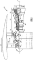
- FIG. 1 schematically illustrates an example gas turbine engine 20 that includes a fan section 22, a compressor section 24, a combustor section 26 and a turbine section 28.
- Alternative engines might include an augmenter section (not shown) among other systems or features.
- the fan section 22 drives air along a bypass flow path B while the compressor section 24 draws air in along a core flow path C where air is compressed and communicated to a combustor section 26.
- air is mixed with fuel and ignited to generate a high energy exhaust gas stream that expands through the turbine section 28 where energy is extracted and utilized to drive the fan section 22 and the compressor section 24.
- a turbine engine including a three-spool architecture in which three spools concentrically rotate about a common axis and where a low spool enables a low pressure turbine to drive a fan via a gearbox, an intermediate spool that enables an intermediate pressure turbine to drive a first compressor of the compressor section, and a high spool that enables a high pressure turbine to drive a high pressure compressor of the compressor section.
- the example engine 20 generally includes a low speed spool 30 and a high speed spool 32 mounted for rotation about an engine central longitudinal axis A relative to an engine static structure 36 via several bearing systems 38. It should be understood that various bearing systems 38 at various locations may alternatively or additionally be provided.
- the low speed spool 30 generally includes an inner shaft 40 that connects a fan 42 and a low pressure (or first) compressor section 44 to a low pressure (or first) turbine section 46.
- the inner shaft 40 drives the fan 42 through a speed change device, such as a geared architecture 48, to drive the fan 42 at a lower speed than the low speed spool 30.
- the high-speed spool 32 includes an outer shaft 50 that interconnects a high pressure (or second) compressor section 52 and a high pressure (or second) turbine section 54.
- the inner shaft 40 and the outer shaft 50 are concentric and rotate via the bearing systems 38 about the engine central longitudinal axis A.
- a combustor 56 is arranged between the high pressure compressor 52 and the high pressure turbine 54.
- the high pressure turbine 54 includes at least two stages to provide a double stage high pressure turbine 54.
- the high pressure turbine 54 includes only a single stage.
- a "high pressure" compressor or turbine experiences a higher pressure than a corresponding "low pressure” compressor or turbine.
- the example low pressure turbine 46 has a pressure ratio that is greater than about 5.
- the pressure ratio of the example low pressure turbine 46 is measured prior to an inlet of the low pressure turbine 46 as related to the pressure measured at the outlet of the low pressure turbine 46 prior to an exhaust nozzle.
- a mid-turbine frame 58 of the engine static structure 36 is arranged generally between the high pressure turbine 54 and the low pressure turbine 46.
- the mid-turbine frame 58 further supports bearing systems 38 in the turbine section 28 as well as setting airflow entering the low pressure turbine 46.
- Airflow through the core airflow path C is compressed by the low pressure compressor 44 then by the high pressure compressor 52 mixed with fuel and ignited in the combustor 56 to produce high speed exhaust gases that are then expanded through the high pressure turbine 54 and low pressure turbine 46.
- the mid-turbine frame 58 includes vanes 60, which are in the core airflow path and function as an inlet guide vane for the low pressure turbine 46. Utilizing the vane 60 of the mid-turbine frame 58 as the inlet guide vane for low pressure turbine 46 decreases the length of the low pressure turbine 46 without increasing the axial length of the mid-turbine frame 58. Reducing or eliminating the number of vanes in the low pressure turbine 46 shortens the axial length of the turbine section 28. Thus, the compactness of the gas turbine engine 20 is increased and a higher power density may be achieved.
- the disclosed gas turbine engine 20 in one example is a high-bypass geared aircraft engine.
- the gas turbine engine 20 includes a bypass ratio greater than about six, with an example embodiment being greater than about ten.
- the example geared architecture 48 is an epicyclical gear train, such as a planetary gear system, star gear system or other known gear system, with a gear reduction ratio of greater than about 2.3.
- the gas turbine engine 20 includes a bypass ratio greater than about ten and the fan diameter is significantly larger than an outer diameter of the low pressure compressor 44. It should be understood, however, that the above parameters are only exemplary of one embodiment of a gas turbine engine including a geared architecture and that the present disclosure is applicable to other gas turbine engines.
- the fan section 22 of the engine 20 is designed for a particular flight condition -- typically cruise at about 0.8 Mach and about 35,000 feet (10,668 m).
- the flight condition of 0.8 Mach and 35,000 ft. (10,668 m), with the engine at its best fuel consumption - also known as "bucket cruise Thrust Specific Fuel Consumption ('TSFC')" - is the industry standard parameter of pound-mass (lbm) of fuel per hour being burned divided by pound-force (lbf) of thrust the engine produces at that minimum point.
- Low fan pressure ratio is the pressure ratio across the fan blade alone, without a Fan Exit Guide Vane (“FEGV”) system.
- the low fan pressure ratio as disclosed herein according to one non-limiting embodiment is less than about 1.50. In another non-limiting embodiment the low fan pressure ratio is less than about 1.45.
- the "Low corrected fan tip speed”, as disclosed herein according to one non-limiting embodiment, is less than about 1150 ft/second (350.5 m/s).
- the example gas turbine engine includes the fan 42 that comprises in one non-limiting embodiment fewer than about 26 fan blades. In another non-limiting embodiment, the fan section 22 includes fewer than about twenty fan blades. Moreover, in one disclosed embodiment the low pressure turbine 46 includes no more than about six turbine rotors schematically indicated at 34. In another non-limiting example embodiment the low pressure turbine 46 includes about three turbine rotors. A ratio between the number of fan blades 42 and the number of low pressure turbine rotors is between about 3.3 and about 8.6. The example low pressure turbine 46 provides the driving power to rotate the fan section 22 and therefore the relationship between the number of turbine rotors 34 in the low pressure turbine 46 and the number of blades 42 in the fan section 22 disclose an example gas turbine engine 20 with increased power transfer efficiency.
- a retaining ring assembly 65 is schematically shown for holding a component 64 within the housing 62.
- the housing 62 is a rotor and the component 64 is an airfoil.
- the example rotor 62 could be within the turbine section 28, the compressor section 24 or part of the fan section 22.
- the airfoil 64 could be a static vane or a rotating blade within the compressor section 24 or the turbine section 28.
- the component 64 maintains a fixed orientation relative to the housing 62. In other words, the housing 62 and the component 64 remain in a specific static relative orientation relative to each other no matter if the housing 62 is rotating or is static feature.
- the component 64 in this example is held within the housing 62 by a retaining ring 66.
- the example retaining ring 66 is disposed within a circumferential slot 76 defined within the housing 62.
- a backing plate 70 is used to abut against the component 64.
- the example backing plate 70 includes a tab 78 that is disposed within an axial space common with the retaining ring 66. Accordingly, the retaining ring 66 is disposed within a radial space between the bottom portion of the circumferential slot 76 and the tab 78.
- the retaining ring 66 is trapped within the radial space between the tab 78 and the circumferential slot 76, it is contained such that it may not move radially outward from the circumferential slot 76 in response to extreme G load events such as jerking or dropping or other extreme conditions encountered by the engine. Moreover, the tab 78 prevents the retaining ring 66 from coming loose of the circumferential slot 76 in response to thermal cycling expansion and contraction.
- the example retaining ring assembly 65 includes the retaining ring 66 that is disposed within the circumferential slot 76 defined within the housing 62.
- the housing 62 includes a back face 68.
- the component 64 includes a first face 86 from which at least two tabs 78 extend. In this example, the at least two tabs 78 extend axially a distance 90. The distance 90 corresponds to a width 92 of the retaining ring 66.
- the component 64 includes a second face 88 that abuts a back face 68 of the housing 62.
- the housing 62 includes an outer diameter surface 82 and an inner diameter surface 84. The component 64 is disposed on the inner diameter surface 84 and trapped axially between the back face 88 and the retaining rings 66.
- the retaining rings 66 are disposed within a radial space 94 defined between a bottom surface of the circumferential slots 76 and the tab 78.
- the tab 78 extends axially a distance 90 from the first face 86. The distance 90 extends past a width 92 of the retaining ring 66. However, it is within the contemplation of this disclosure, that the tab 78 may extend a lesser or greater distance axially relative to a width of the retaining ring 66.
- the tab 78 need only extend a partial axial distance such that it overlaps the retaining ring 66.
- the component 64 includes a plurality of tabs 78.
- the component 64 includes four tabs 78.
- the number of tabs 78 may vary and include at least more than two tabs 78 disposed circumferentially about the component 64.
- the tabs 78 are spaced a circumferential distance 102 apart from each other such that they are spaced about the circumference of the component 64.
- the disclosed example embodiment includes the tabs 78 as an integral part of the component 64.
- the tab 78 may be a separate part that is attached to the component 64 during assembly. Accordingly, the tab 78 may be an integral part or a separable part that is assembled to the component 64. In either configuration, each of the tabs 78 are disposed such that they axially overlap the retaining rings 66 and prevent and constrain retaining rings 66 radially to maintain within the circumferential slot 76.
- the tabs 78 include a circumferential width 75 that provides sufficient material to contain the retaining ring 66 and provide sufficient structure to meet operational and durability requirements.
- the retaining ring extends radially inward from an inner diameter 84 of the housing 62.
- the retaining ring 66 is a split ring that includes a split 96 that enables assembly within the circumferential slot.
- the split 96 enables the retaining ring 66 to be compressed or expanded to enable assembly into the circumferential slot 76.
- the retaining ring 66 may not be expanded or contracted to be inserted into the circumferential slot 76. Instead, a first end 98 of the retaining ring 66 is inserted into the circumferential slot 76 within the radial space 94 and pushed within the circumferential slot 76 between the tabs 78 until the second end 100 is received within the circumferential slot 76.
- the split portion 96 may then be orientated relative to a circumferential location where one of the tabs 78 is present.
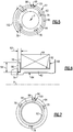
- the split 96 may be orientated such that it is between adjacent tabs 78 as is illustrated in Figure 4 . In any of these orientations, the tabs 78 prevent radial movement of the retaining ring 66 out of the circumferential slot 76.
- FIG. 6 an alternate disclosed embodiment is illustrated where the component 64 is disposed on an outer diameter of the housing 62.
- the circumferential slot 76 is disposed on an outer diameter of the housing 62 and the retaining ring 66 is disposed within that circumferential slot.
- the component 64 is still abutted against a back face 68 of the housing 62.
- the retaining ring 66 remains confined within the radial space 94 between bottom of the circumferential slot 76 and the tab 78.
- Each of the tabs 78 extend a distance 92 that corresponds with an axial width of the retaining ring 66.
- the specific number of tabs 78 may vary but will include two tabs 78 that are disposed in a circumferentially spaced manner to inhibit and constrain the retaining ring 66 to maintain it within the circumferential slot 76.
- the example retaining ring assembly 65 includes the tabs 78 that contain and confine the retaining ring 66 within the circumferential slot 76 such that the retaining ring 66 is not susceptible to errant dislodgement during engine operation or in response to extreme conditions and circumstance.
Landscapes
- Engineering & Computer Science (AREA)
- Mechanical Engineering (AREA)
- General Engineering & Computer Science (AREA)
- Ceramic Engineering (AREA)
- Structures Of Non-Positive Displacement Pumps (AREA)
Abstract
Description
- A gas turbine engine typically includes a fan section, a compressor section, a combustor section and a turbine section. Air entering the compressor section is compressed and delivered into the combustion section where it is mixed with fuel and ignited to generate a high-speed exhaust gas flow. The high-speed exhaust gas flow expands through the turbine section to drive the compressor and the fan section. The compressor section typically includes low and high pressure compressors, and the turbine section includes low and high pressure turbines.
- Retaining rings are utilized throughout a gas turbine engine to axially retain mated components. Typical retaining rings include a split that enables the ring to be forced open for assembly into a circumferential slot. The retaining ring remains within the slot due to the size and material characteristics that resist expansion. However, an improper size or material selection may enable the ring to become dislodged from the circumferential slot. Dislodgement of a retaining ring may free the mated components or become free within the rotating structures of the gas turbine engine.
- Turbine engine manufacturers continue to seek further improvements to engine assembly and durability.
- In a featured embodiment, a component retaining assembly includes a housing including a circumferential slot. A component is mated to the housing. The component includes a first face including at least two tabs. The at least two tabs extending at outward from the first face at least partially past a portion of the circumferential slot. A retaining ring is disposed within the circumferential slot and abuts the first face of the component. The at least two tabs overlap a portion of the retaining ring.
- In another embodiment according to the previous embodiment, the housing includes a back face and the component includes a second face spaced axially apart from the first face with the second face abutting the back face of the housing.
- In another embodiment according to any of the previous embodiments, the at least two tabs are circumferentially spaced apart.
- In another embodiment according to any of the previous embodiments, the retaining ring is disposed within a radial space between a bottom surface of the circumferential slot and the at least two tabs.
- In another embodiment according to any of the previous embodiments, the circumferential slot is disposed within an inner diameter of the housing and the retaining ring is disposed radially outward of the at least two tabs.
- In another embodiment according to any of the previous embodiments, the circumferential slot is disposed on an outer diameter of the housing and the retaining ring is disposed radially inward of the at least two tabs.
- In another embodiment according to any of the previous embodiments, the retaining ring includes a split configured to enable expansion for assembly into the circumferential slot.
- In another embodiment according to any of the previous embodiments, the component is fixed relative to the housing.
- In another featured embodiment, a gas turbine engine includes a housing disposed about an engine axis. The housing includes a circumferential slot. A component is mated to the housing. The component includes at least two axially extending tabs. A retaining ring is disposed within the circumferential slot for axially retaining the component to the housing. The retaining ring is disposed within a radial space between the circumferential slot and the at least two axially extending tabs.
- In another embodiment according to the previous embodiment, the component is fixed relative to the housing.
- In another embodiment according to any of the previous embodiments, the housing is rotatable about the engine axis.
- In another embodiment according to any of the previous embodiments, the housing defines a rotor and the component defines a portion of an airfoil assembly.
- In another embodiment according to any of the previous embodiments, the retaining ring includes a split configured to enable expansion for assembly into the circumferential slot.
- In another embodiment according to any of the previous embodiments, the circumferential slot is disposed within an inner diameter of the housing and the retaining ring is disposed radially outward of the at least two tabs.
- In another embodiment according to any of the previous embodiments, the circumferential slot is disposed on an outer diameter of the housing and the retaining ring is disposed radially inward of the at least two tabs.
- In another featured embodiment, a method of axially retaining a component to a housing includes defining the housing to include a circumferential slot. The component is defined to include at least two axially extending tabs. A first end of a retaining ring is inserted into a radial space between the circumferential slot and one of the at least two axially extending tabs. The first end is pushed within the circumferential slot until a second end of the retaining ring enters the circumferential slot and is disposed within the radial space.
- In another embodiment according to the previous embodiment, includes abutting a first face of the component with the retaining ring for holding the component against a back face of the housing.
- In another embodiment according to any of the previous embodiments, includes sizing the retaining ring to include an inner diameter corresponding with a bottom surface of the circumferential slot and a radial width less than a width of the radial space between the circumferential slot and the at least two axially extending tabs.
- Although the different examples have the specific components shown in the illustrations, embodiments of this disclosure are not limited to those particular combinations. It is possible to use some of the components or features from one of the examples in combination with features or components from another one of the examples.
- These and other features disclosed herein can be best understood from the following specification and drawings, the following of which is a brief description.
-
-
Figure 1 schematically shows an embodiment of a gas turbine engine. -
Figure 2 schematically shows an embodiment of a retaining ring assembly securing an airfoil component. -
Figure 3 is a cross sectional view of the retaining ring assembly. -
Figure 4 is a perspective view of a portion of a retaining ring assembly. -
Figure 5 is an axially looking view of the retaining ring assembly. -
Figure 6 is a cross section of another retaining ring assembly. -
Figure 7 is an axially looking view of the retaining ring assembly. -
Figure 1 schematically illustrates an examplegas turbine engine 20 that includes afan section 22, acompressor section 24, acombustor section 26 and aturbine section 28. Alternative engines might include an augmenter section (not shown) among other systems or features. Thefan section 22 drives air along a bypass flow path B while thecompressor section 24 draws air in along a core flow path C where air is compressed and communicated to acombustor section 26. In thecombustor section 26, air is mixed with fuel and ignited to generate a high energy exhaust gas stream that expands through theturbine section 28 where energy is extracted and utilized to drive thefan section 22 and thecompressor section 24. - Although the disclosed non-limiting embodiment depicts a two-spool turbofan gas turbine engine, it should be understood that the concepts described herein are not limited to use with two-spool turbofans as the teachings may be applied to other types of turbine engines; for example a turbine engine including a three-spool architecture in which three spools concentrically rotate about a common axis and where a low spool enables a low pressure turbine to drive a fan via a gearbox, an intermediate spool that enables an intermediate pressure turbine to drive a first compressor of the compressor section, and a high spool that enables a high pressure turbine to drive a high pressure compressor of the compressor section.
- The
example engine 20 generally includes alow speed spool 30 and ahigh speed spool 32 mounted for rotation about an engine central longitudinal axis A relative to an enginestatic structure 36 viaseveral bearing systems 38. It should be understood thatvarious bearing systems 38 at various locations may alternatively or additionally be provided. - The
low speed spool 30 generally includes aninner shaft 40 that connects afan 42 and a low pressure (or first) compressor section 44 to a low pressure (or first)turbine section 46. Theinner shaft 40 drives thefan 42 through a speed change device, such as a gearedarchitecture 48, to drive thefan 42 at a lower speed than thelow speed spool 30. The high-speed spool 32 includes anouter shaft 50 that interconnects a high pressure (or second)compressor section 52 and a high pressure (or second)turbine section 54. Theinner shaft 40 and theouter shaft 50 are concentric and rotate via the bearingsystems 38 about the engine central longitudinal axis A. - A
combustor 56 is arranged between thehigh pressure compressor 52 and thehigh pressure turbine 54. In one example, thehigh pressure turbine 54 includes at least two stages to provide a double stagehigh pressure turbine 54. In another example, thehigh pressure turbine 54 includes only a single stage. As used herein, a "high pressure" compressor or turbine experiences a higher pressure than a corresponding "low pressure" compressor or turbine. - The example
low pressure turbine 46 has a pressure ratio that is greater than about 5. The pressure ratio of the examplelow pressure turbine 46 is measured prior to an inlet of thelow pressure turbine 46 as related to the pressure measured at the outlet of thelow pressure turbine 46 prior to an exhaust nozzle. - A
mid-turbine frame 58 of the enginestatic structure 36 is arranged generally between thehigh pressure turbine 54 and thelow pressure turbine 46. Themid-turbine frame 58 furthersupports bearing systems 38 in theturbine section 28 as well as setting airflow entering thelow pressure turbine 46. - Airflow through the core airflow path C is compressed by the low pressure compressor 44 then by the
high pressure compressor 52 mixed with fuel and ignited in thecombustor 56 to produce high speed exhaust gases that are then expanded through thehigh pressure turbine 54 andlow pressure turbine 46. Themid-turbine frame 58 includesvanes 60, which are in the core airflow path and function as an inlet guide vane for thelow pressure turbine 46. Utilizing thevane 60 of themid-turbine frame 58 as the inlet guide vane forlow pressure turbine 46 decreases the length of thelow pressure turbine 46 without increasing the axial length of themid-turbine frame 58. Reducing or eliminating the number of vanes in thelow pressure turbine 46 shortens the axial length of theturbine section 28. Thus, the compactness of thegas turbine engine 20 is increased and a higher power density may be achieved. - The disclosed
gas turbine engine 20 in one example is a high-bypass geared aircraft engine. In a further example, thegas turbine engine 20 includes a bypass ratio greater than about six, with an example embodiment being greater than about ten. The example gearedarchitecture 48 is an epicyclical gear train, such as a planetary gear system, star gear system or other known gear system, with a gear reduction ratio of greater than about 2.3. - In one disclosed embodiment, the
gas turbine engine 20 includes a bypass ratio greater than about ten and the fan diameter is significantly larger than an outer diameter of the low pressure compressor 44. It should be understood, however, that the above parameters are only exemplary of one embodiment of a gas turbine engine including a geared architecture and that the present disclosure is applicable to other gas turbine engines. - A significant amount of thrust is provided by the bypass flow B due to the high bypass ratio. The
fan section 22 of theengine 20 is designed for a particular flight condition -- typically cruise at about 0.8 Mach and about 35,000 feet (10,668 m). The flight condition of 0.8 Mach and 35,000 ft. (10,668 m), with the engine at its best fuel consumption - also known as "bucket cruise Thrust Specific Fuel Consumption ('TSFC')" - is the industry standard parameter of pound-mass (lbm) of fuel per hour being burned divided by pound-force (lbf) of thrust the engine produces at that minimum point. - "Low fan pressure ratio" is the pressure ratio across the fan blade alone, without a Fan Exit Guide Vane ("FEGV") system. The low fan pressure ratio as disclosed herein according to one non-limiting embodiment is less than about 1.50. In another non-limiting embodiment the low fan pressure ratio is less than about 1.45.
- "Low corrected fan tip speed" is the actual fan tip speed in ft/sec divided by an industry standard temperature correction of [(Tram °R)/(518.7°R)]0.5(where °R = K x 9/5). The "Low corrected fan tip speed", as disclosed herein according to one non-limiting embodiment, is less than about 1150 ft/second (350.5 m/s).
- The example gas turbine engine includes the
fan 42 that comprises in one non-limiting embodiment fewer than about 26 fan blades. In another non-limiting embodiment, thefan section 22 includes fewer than about twenty fan blades. Moreover, in one disclosed embodiment thelow pressure turbine 46 includes no more than about six turbine rotors schematically indicated at 34. In another non-limiting example embodiment thelow pressure turbine 46 includes about three turbine rotors. A ratio between the number offan blades 42 and the number of low pressure turbine rotors is between about 3.3 and about 8.6. The examplelow pressure turbine 46 provides the driving power to rotate thefan section 22 and therefore the relationship between the number ofturbine rotors 34 in thelow pressure turbine 46 and the number ofblades 42 in thefan section 22 disclose an examplegas turbine engine 20 with increased power transfer efficiency. - Referring to
Figure 2 with continued reference toFigure 1 , a retainingring assembly 65 is schematically shown for holding acomponent 64 within thehousing 62. In this example, thehousing 62 is a rotor and thecomponent 64 is an airfoil. Theexample rotor 62 could be within theturbine section 28, thecompressor section 24 or part of thefan section 22. Theairfoil 64 could be a static vane or a rotating blade within thecompressor section 24 or theturbine section 28. In any of these examples, thecomponent 64 maintains a fixed orientation relative to thehousing 62. In other words, thehousing 62 and thecomponent 64 remain in a specific static relative orientation relative to each other no matter if thehousing 62 is rotating or is static feature. - The
component 64 in this example is held within thehousing 62 by a retainingring 66. Theexample retaining ring 66 is disposed within acircumferential slot 76 defined within thehousing 62. In this example, abacking plate 70 is used to abut against thecomponent 64. Theexample backing plate 70 includes atab 78 that is disposed within an axial space common with the retainingring 66. Accordingly, the retainingring 66 is disposed within a radial space between the bottom portion of thecircumferential slot 76 and thetab 78. Because the retainingring 66 is trapped within the radial space between thetab 78 and thecircumferential slot 76, it is contained such that it may not move radially outward from thecircumferential slot 76 in response to extreme G load events such as jerking or dropping or other extreme conditions encountered by the engine. Moreover, thetab 78 prevents the retainingring 66 from coming loose of thecircumferential slot 76 in response to thermal cycling expansion and contraction. - Referring to
Figures 3 and 4 , the example retainingring assembly 65 includes the retainingring 66 that is disposed within thecircumferential slot 76 defined within thehousing 62. Thehousing 62 includes aback face 68. Thecomponent 64 includes afirst face 86 from which at least twotabs 78 extend. In this example, the at least twotabs 78 extend axially adistance 90. Thedistance 90 corresponds to awidth 92 of the retainingring 66. Thecomponent 64 includes asecond face 88 that abuts aback face 68 of thehousing 62. In this example, thehousing 62 includes anouter diameter surface 82 and aninner diameter surface 84. Thecomponent 64 is disposed on theinner diameter surface 84 and trapped axially between theback face 88 and the retaining rings 66. - The retaining rings 66 are disposed within a
radial space 94 defined between a bottom surface of thecircumferential slots 76 and thetab 78. Thetab 78 extends axially adistance 90 from thefirst face 86. Thedistance 90 extends past awidth 92 of the retainingring 66. However, it is within the contemplation of this disclosure, that thetab 78 may extend a lesser or greater distance axially relative to a width of the retainingring 66. Thetab 78 need only extend a partial axial distance such that it overlaps the retainingring 66. - Referring to
Figure 5 with continued reference toFigures 3 and 4 , thecomponent 64 includes a plurality oftabs 78. In this example, thecomponent 64 includes fourtabs 78. However, the number oftabs 78 may vary and include at least more than twotabs 78 disposed circumferentially about thecomponent 64. Thetabs 78 are spaced acircumferential distance 102 apart from each other such that they are spaced about the circumference of thecomponent 64. - The disclosed example embodiment includes the
tabs 78 as an integral part of thecomponent 64. Thetab 78 may be a separate part that is attached to thecomponent 64 during assembly. Accordingly, thetab 78 may be an integral part or a separable part that is assembled to thecomponent 64. In either configuration, each of thetabs 78 are disposed such that they axially overlap the retaining rings 66 and prevent and constrain retainingrings 66 radially to maintain within thecircumferential slot 76. Thetabs 78 include acircumferential width 75 that provides sufficient material to contain the retainingring 66 and provide sufficient structure to meet operational and durability requirements. - In the disclosed example illustrated in
Figures 3, 4 and5 , the retaining ring extends radially inward from aninner diameter 84 of thehousing 62. The retainingring 66 is a split ring that includes asplit 96 that enables assembly within the circumferential slot. - The
split 96 enables the retainingring 66 to be compressed or expanded to enable assembly into thecircumferential slot 76. However, because thetabs 78 are included, the retainingring 66 may not be expanded or contracted to be inserted into thecircumferential slot 76. Instead, afirst end 98 of the retainingring 66 is inserted into thecircumferential slot 76 within theradial space 94 and pushed within thecircumferential slot 76 between thetabs 78 until thesecond end 100 is received within thecircumferential slot 76. Thesplit portion 96 may then be orientated relative to a circumferential location where one of thetabs 78 is present. Moreover, thesplit 96 may be orientated such that it is betweenadjacent tabs 78 as is illustrated inFigure 4 . In any of these orientations, thetabs 78 prevent radial movement of the retainingring 66 out of thecircumferential slot 76. - Referring to
Figures 6 and 7 , an alternate disclosed embodiment is illustrated where thecomponent 64 is disposed on an outer diameter of thehousing 62. In this example, thecircumferential slot 76 is disposed on an outer diameter of thehousing 62 and the retainingring 66 is disposed within that circumferential slot. Thecomponent 64 is still abutted against aback face 68 of thehousing 62. The retainingring 66 remains confined within theradial space 94 between bottom of thecircumferential slot 76 and thetab 78. Each of thetabs 78 extend adistance 92 that corresponds with an axial width of the retainingring 66. In the example disclosed inFigure 7 , there are threetabs 78 disposed circumferentially apart. As appreciated, the specific number oftabs 78 may vary but will include twotabs 78 that are disposed in a circumferentially spaced manner to inhibit and constrain the retainingring 66 to maintain it within thecircumferential slot 76. - The example retaining
ring assembly 65 includes thetabs 78 that contain and confine the retainingring 66 within thecircumferential slot 76 such that the retainingring 66 is not susceptible to errant dislodgement during engine operation or in response to extreme conditions and circumstance. - Although an example embodiment has been disclosed, a worker of ordinary skill in this art would recognize that certain modifications would come within the scope of this disclosure. For that reason, the following claims should be studied to determine the scope and content of this disclosure.
Claims (14)
- A component retaining assembly (65) comprising:a housing (62) including a circumferential slot (76);a component (64) mated to the housing (62), the component (64) including a first face (86) including at least two tabs (78), the at least two tabs (78) extending outward from the first face (86) at least partially past a portion of the circumferential slot (76); anda retaining ring (66) disposed within the circumferential slot (76) and abutting the first face (86) of the component (64), wherein the at least two tabs (78) overlap a portion of the retaining ring (66).
- The assembly (65) as recited in claim 1, wherein the housing (62) includes a back face (68) and the component (64) includes a second face (83) spaced axially apart from the first face (86) with the second face (88) abutting the back face (68) of the housing (62).
- The assembly (65) as recited in claim 1 or 2, wherein the at least two tabs (78) are circumferentially spaced apart.
- The assembly (65) as recited in any of claims 1 to 3, wherein the retaining ring (66) is disposed within a radial space (94) between a bottom surface of the circumferential slot (76) and the at least two tabs (78).
- A gas turbine engine (20) comprising;
a housing (62) disposed about an engine axis (A), the housing (62) including a circumferential slot (76);
a component (64) mated to the housing (62), the component (64) including at least two axially extending tabs (78); and
a retaining ring (66) disposed within the circumferential slot (76) for axially retaining the component (64) to the housing (62), the retaining ring (66) disposed within a radial space (94) between the circumferential slot (76) and the at least two axially extending tabs (78). - The gas turbine engine (20) or assembly (65) as recited in any preceding claim, wherein the component (64) is fixed relative to the housing (62).
- The gas turbine engine (20) as recited in claim 5 or 6, wherein the housing (62) is rotatable about the engine axis (A).
- The gas turbine engine (20) or assembly (65) as recited in any preceding claim, wherein the housing (62) defines a rotor and the component (64) defines a portion of an airfoil assembly.
- The gas turbine engine (20) or assembly (65) as recited in any preceding claim, wherein the retaining ring (66) includes a split (96) configured to enable expansion for assembly into the circumferential slot (76).
- The gas turbine engine (20) or assembly (65) as recited in any preceding claim, wherein the circumferential slot (76) is disposed within an inner diameter (84) of the housing (62) and the retaining ring (66) is disposed radially outward of the at least two tabs (78).
- The gas turbine engine (20) or assembly (65) as recited in any of claims 1 to 9, wherein the circumferential slot (76) is disposed on an outer diameter (82) of the housing (62) and the retaining ring (66) is disposed radially inward of the at least two tabs (78).
- A method of axially retaining a component (64) to a housing (62) comprising:defining the housing (62) to include a circumferential slot (76);defining the component (64) to include at least two axially extending tabs (78);inserting a first end (98) of a retaining ring (66) into a radial space (94) between the circumferential slot (76) and one of the at least two axially extending tabs (78); andpushing the first end (98) within the circumferential slot (76) until a second end (100) of the retaining ring (66) enters the circumferential slot (76) and is disposed within the radial space (94).
- The method as recited in claim 12, including abutting a first face (86) of the component with the retaining ring (66) for holding the component (64) against a back face (68) of the housing (62).
- The method as recited in claim 12 or 13, including sizing the retaining ring (66) to include an inner diameter corresponding with a bottom surface of the circumferential slot (76) and a radial width less than a width of the radial space (94) between the circumferential slot (76) and the at least two axially extending tabs (78).
Priority Applications (1)
| Application Number | Priority Date | Filing Date | Title |
|---|---|---|---|
| EP26167365.1A EP4737690A2 (en) | 2016-09-01 | 2017-08-31 | Gas turbine engine with a retaining assembly of a rotor blade with tabs and retaining ring |
Applications Claiming Priority (1)
| Application Number | Priority Date | Filing Date | Title |
|---|---|---|---|
| US15/253,957 US10724384B2 (en) | 2016-09-01 | 2016-09-01 | Intermittent tab configuration for retaining ring retention |
Related Child Applications (1)
| Application Number | Title | Priority Date | Filing Date |
|---|---|---|---|
| EP26167365.1A Division EP4737690A2 (en) | 2016-09-01 | 2017-08-31 | Gas turbine engine with a retaining assembly of a rotor blade with tabs and retaining ring |
Publications (2)
| Publication Number | Publication Date |
|---|---|
| EP3290640A1 true EP3290640A1 (en) | 2018-03-07 |
| EP3290640B1 EP3290640B1 (en) | 2026-03-25 |
Family
ID=59745825
Family Applications (2)
| Application Number | Title | Priority Date | Filing Date |
|---|---|---|---|
| EP17188824.1A Active EP3290640B1 (en) | 2016-09-01 | 2017-08-31 | Gas turbine engine with a retaining assembly of a rotor blade with tabs and retaining ring |
| EP26167365.1A Pending EP4737690A2 (en) | 2016-09-01 | 2017-08-31 | Gas turbine engine with a retaining assembly of a rotor blade with tabs and retaining ring |
Family Applications After (1)
| Application Number | Title | Priority Date | Filing Date |
|---|---|---|---|
| EP26167365.1A Pending EP4737690A2 (en) | 2016-09-01 | 2017-08-31 | Gas turbine engine with a retaining assembly of a rotor blade with tabs and retaining ring |
Country Status (2)
| Country | Link |
|---|---|
| US (1) | US10724384B2 (en) |
| EP (2) | EP3290640B1 (en) |
Citations (4)
| Publication number | Priority date | Publication date | Assignee | Title |
|---|---|---|---|---|
| US3656865A (en) * | 1970-07-21 | 1972-04-18 | Gen Motors Corp | Rotor blade retainer |
| WO2010067024A2 (en) * | 2008-12-11 | 2010-06-17 | Turbomeca | Turbine wheel provided with an axial retention device that locks blades in relation to a disk |
| FR2951224A1 (en) * | 2009-10-13 | 2011-04-15 | Turbomeca | TURBINE WHEEL EQUIPPED WITH AXIAL RETAINING JONC LOCKING BLADES IN RELATION TO A DISK |
| US20130156589A1 (en) * | 2011-12-15 | 2013-06-20 | Pratt & Whitney Canada Corp. | Turbine rotor retaining system |
Family Cites Families (15)
| Publication number | Priority date | Publication date | Assignee | Title |
|---|---|---|---|---|
| US3043562A (en) * | 1961-04-10 | 1962-07-10 | Gen Electric | Combination sealing and restraining member for long-shank turbo-machine buckets |
| US5256035A (en) * | 1992-06-01 | 1993-10-26 | United Technologies Corporation | Rotor blade retention and sealing construction |
| US5257909A (en) * | 1992-08-17 | 1993-11-02 | General Electric Company | Dovetail sealing device for axial dovetail rotor blades |
| US5302086A (en) * | 1992-08-18 | 1994-04-12 | General Electric Company | Apparatus for retaining rotor blades |
| US5338154A (en) | 1993-03-17 | 1994-08-16 | General Electric Company | Turbine disk interstage seal axial retaining ring |
| US5484242A (en) | 1994-07-12 | 1996-01-16 | Deere & Company | Snap ring retaining washer |
| US6533550B1 (en) * | 2001-10-23 | 2003-03-18 | Pratt & Whitney Canada Corp. | Blade retention |
| DE10348198A1 (en) * | 2003-10-16 | 2005-05-12 | Rolls Royce Deutschland | Scoop restraint |
| US7197807B2 (en) | 2004-03-22 | 2007-04-03 | General Motors Corporation | Castellated snap ring retention system and method |
| FR2868808B1 (en) | 2004-04-09 | 2008-08-29 | Snecma Moteurs Sa | DEVICE FOR THE AXIAL RETENTION OF AUBES ON A ROTOR DISC OF A TURBOMACHINE |
| FR2918106B1 (en) | 2007-06-27 | 2011-05-06 | Snecma | AXIS RETAINING DEVICE OF AUBES MOUNTED ON A TURBOMACHINE ROTOR DISC. |
| US8961141B2 (en) * | 2011-08-29 | 2015-02-24 | United Technologies Corporation | Axial retention system for a bladed rotor with multiple blade types |
| US20130323052A1 (en) * | 2012-05-31 | 2013-12-05 | Solar Turbines Inc. | Retaining ring |
| CN104981616B (en) | 2012-12-13 | 2017-09-26 | 马克卡车公司 | Retaining ring retention system and method |
| US9567857B2 (en) | 2013-03-08 | 2017-02-14 | Rolls-Royce North American Technologies, Inc. | Turbine split ring retention and anti-rotation method |
-
2016
- 2016-09-01 US US15/253,957 patent/US10724384B2/en active Active
-
2017
- 2017-08-31 EP EP17188824.1A patent/EP3290640B1/en active Active
- 2017-08-31 EP EP26167365.1A patent/EP4737690A2/en active Pending
Patent Citations (4)
| Publication number | Priority date | Publication date | Assignee | Title |
|---|---|---|---|---|
| US3656865A (en) * | 1970-07-21 | 1972-04-18 | Gen Motors Corp | Rotor blade retainer |
| WO2010067024A2 (en) * | 2008-12-11 | 2010-06-17 | Turbomeca | Turbine wheel provided with an axial retention device that locks blades in relation to a disk |
| FR2951224A1 (en) * | 2009-10-13 | 2011-04-15 | Turbomeca | TURBINE WHEEL EQUIPPED WITH AXIAL RETAINING JONC LOCKING BLADES IN RELATION TO A DISK |
| US20130156589A1 (en) * | 2011-12-15 | 2013-06-20 | Pratt & Whitney Canada Corp. | Turbine rotor retaining system |
Also Published As
| Publication number | Publication date |
|---|---|
| US10724384B2 (en) | 2020-07-28 |
| EP3290640B1 (en) | 2026-03-25 |
| EP4737690A2 (en) | 2026-05-06 |
| US20180058229A1 (en) | 2018-03-01 |
Similar Documents
| Publication | Publication Date | Title |
|---|---|---|
| EP2920428B1 (en) | Carrier interlock | |
| EP3030754B1 (en) | Boas with radial load feature | |
| EP2880278B1 (en) | Anti-rotation lug for a gas turbine engine stator assembly | |
| US9376926B2 (en) | Gas turbine engine fan blade lock assembly | |
| US10458265B2 (en) | Integrally bladed rotor | |
| EP2880282B1 (en) | Compressor assembly with stator anti-rotation lug | |
| EP2964522B1 (en) | Gas turbine engine nose cone attachment | |
| US20140255196A1 (en) | Double split blade lock ring | |
| US10927768B2 (en) | Spline ring for a fan drive gear flexible support | |
| EP2943658B1 (en) | Stator anti-rotation device | |
| EP3611347B1 (en) | Gas turbine engine with stator segments | |
| EP3290640B1 (en) | Gas turbine engine with a retaining assembly of a rotor blade with tabs and retaining ring | |
| EP3404215B1 (en) | Gas turbine engine with seal anti-rotation lock | |
| US20160010460A1 (en) | Pretrenched rotor for gas turbine engine | |
| WO2014092909A1 (en) | Multi-piece blade for gas turbine engine | |
| EP3228856A1 (en) | Fan blade removal feature for a gas turbine engine | |
| WO2014047038A1 (en) | Multi-stage high pressure compressor case | |
| EP2855846A2 (en) | Shield slot on side of load slot in gas turbine engine rotor |
Legal Events
| Date | Code | Title | Description |
|---|---|---|---|
| PUAI | Public reference made under article 153(3) epc to a published international application that has entered the european phase |
Free format text: ORIGINAL CODE: 0009012 |
|
| STAA | Information on the status of an ep patent application or granted ep patent |
Free format text: STATUS: THE APPLICATION HAS BEEN PUBLISHED |
|
| AK | Designated contracting states |
Kind code of ref document: A1 Designated state(s): AL AT BE BG CH CY CZ DE DK EE ES FI FR GB GR HR HU IE IS IT LI LT LU LV MC MK MT NL NO PL PT RO RS SE SI SK SM TR |
|
| AX | Request for extension of the european patent |
Extension state: BA ME |
|
| STAA | Information on the status of an ep patent application or granted ep patent |
Free format text: STATUS: REQUEST FOR EXAMINATION WAS MADE |
|
| 17P | Request for examination filed |
Effective date: 20180907 |
|
| RBV | Designated contracting states (corrected) |
Designated state(s): AL AT BE BG CH CY CZ DE DK EE ES FI FR GB GR HR HU IE IS IT LI LT LU LV MC MK MT NL NO PL PT RO RS SE SI SK SM TR |
|
| STAA | Information on the status of an ep patent application or granted ep patent |
Free format text: STATUS: EXAMINATION IS IN PROGRESS |
|
| 17Q | First examination report despatched |
Effective date: 20201216 |
|
| RAP1 | Party data changed (applicant data changed or rights of an application transferred) |
Owner name: RAYTHEON TECHNOLOGIES CORPORATION |
|
| RAP3 | Party data changed (applicant data changed or rights of an application transferred) |
Owner name: RTX CORPORATION |
|
| GRAP | Despatch of communication of intention to grant a patent |
Free format text: ORIGINAL CODE: EPIDOSNIGR1 |
|
| STAA | Information on the status of an ep patent application or granted ep patent |
Free format text: STATUS: GRANT OF PATENT IS INTENDED |
|
| INTG | Intention to grant announced |
Effective date: 20251014 |
|
| GRAS | Grant fee paid |
Free format text: ORIGINAL CODE: EPIDOSNIGR3 |
|
| GRAA | (expected) grant |
Free format text: ORIGINAL CODE: 0009210 |
|
| STAA | Information on the status of an ep patent application or granted ep patent |
Free format text: STATUS: THE PATENT HAS BEEN GRANTED |
|
| AK | Designated contracting states |
Kind code of ref document: B1 Designated state(s): AL AT BE BG CH CY CZ DE DK EE ES FI FR GB GR HR HU IE IS IT LI LT LU LV MC MK MT NL NO PL PT RO RS SE SI SK SM TR |
|
| REG | Reference to a national code |
Ref country code: CH Ref legal event code: F10 Free format text: ST27 STATUS EVENT CODE: U-0-0-F10-F00 (AS PROVIDED BY THE NATIONAL OFFICE) Effective date: 20260325 Ref country code: GB Ref legal event code: FG4D |
|
| REG | Reference to a national code |
Ref country code: DE Ref legal event code: R096 Ref document number: 602017094434 Country of ref document: DE |
|
| REG | Reference to a national code |
Ref country code: IE Ref legal event code: FG4D |