EP3290604A1 - Pump station comprising a flush pipe - Google Patents
Pump station comprising a flush pipe Download PDFInfo
- Publication number
- EP3290604A1 EP3290604A1 EP16186113.3A EP16186113A EP3290604A1 EP 3290604 A1 EP3290604 A1 EP 3290604A1 EP 16186113 A EP16186113 A EP 16186113A EP 3290604 A1 EP3290604 A1 EP 3290604A1
- Authority
- EP
- European Patent Office
- Prior art keywords
- tank
- flush pipe
- pump
- liquid level
- valve
- Prior art date
- Legal status (The legal status is an assumption and is not a legal conclusion. Google has not performed a legal analysis and makes no representation as to the accuracy of the status listed.)
- Granted
Links
Images

Classifications
-
- E—FIXED CONSTRUCTIONS
- E03—WATER SUPPLY; SEWERAGE
- E03F—SEWERS; CESSPOOLS
- E03F5/00—Sewerage structures
- E03F5/22—Adaptations of pumping plants for lifting sewage
-
- E—FIXED CONSTRUCTIONS
- E03—WATER SUPPLY; SEWERAGE
- E03F—SEWERS; CESSPOOLS
- E03F5/00—Sewerage structures
- E03F5/10—Collecting-tanks; Equalising-tanks for regulating the run-off; Laying-up basins
- E03F5/105—Accessories, e.g. flow regulators or cleaning devices
Definitions
- the present invention relates generally to the field of pump stations for intermediate storage of liquid, and relates specifically to the field of pump stations for intermediate storage of wastewater, sewage, etc.
- the pump station comprises a tank configured to house said liquid, an inlet for influent liquid flow, a pump configured to intermittently discharge liquid from the tank and an outlet for effluent liquid flow.
- Pump stations of the above type are regularly used in wastewater networks at one or more positions between the individual household and the wastewater treatment plant.
- Each pump station comprises at least one pump located in the tank of the pump station, and in many pump stations the pump is operated in an ON/OFF manner. This means that the pump is not active all the times but is instead configured to intermittently discharge liquid from the tank.
- One commonly used operational strategy is to have a pump start liquid level of the tank and a pump stop liquid level of the tank, wherein the pump start liquid level is located above the pump stop liquid level. Thus, when the liquid level in the tank reaches the pump start liquid level the pump is started/activated, and when the liquid level in the tank drops below the pump stop liquid level the pump is stopped/deactivated.
- the influent liquid flow comprises solid matter, grease, different cleaning agents, soap, etc.
- a mixture of grease, soap, etc. will accumulate at the surface of the wastewater in the tank and attach/ accumulate to the inner wall of the tank at the pump start liquid level of the tank. Accumulation of grease will have negative effect on the structural elements of the pump station and will generate bad smell. Thereto, solid matter that is too heavy to stay suspended in the liquid will settle and accumulate at the bottom of the tank.
- the present invention aims at obviating the aforementioned disadvantages and failings of previously known pump stations, and at providing an improved pump station.
- a primary object of the present invention is to provide an improved pump station of the initially defined type which is configured to keep the tank free from solid matter, grease, soap, etc. otherwise accumulated in the tank. It is another object of the present invention to provide a pump station, which use no or negligible amounts of energy for the object of keeping the tank clean from accumulating matter.
- a pump station of the initially defined type which is characterized in that the pump station comprises a flush pipe having a lower opening provided in said tank and an upper opening, wherein the lower opening of the flush pipe is located below a pump start liquid level of the tank, and wherein the flush pipe comprises a valve configured to open/close fluid communication between the lower opening of the flush pipe and the upper opening of the flush pipe.
- the present invention is based on the insight of automatic priming of a flush pipe is obtained during normal rise of the liquid level in the tank, wherein the liquid volume in the flush pipe is at a later step used to mix/circulate the wastewater in the tank when the liquid level in the tank is low.
- energy is stored in the flush pipe in the form of a liquid column located above the liquid level of the tank (i.e. a volume of liquid having a certain potential energy in relation to the liquid level in the tank), and no added energy is needed to prime the flush pipe and thereby no added energy is needed to clean the tank from accumulating matter.
- the lower opening of the flush pipe is located below a pump stop liquid level of the tank, wherein the valve is constituted by a controllable valve.
- the lower opening of the flush pipe is located above a pump stop liquid level of the tank, wherein the valve is constituted by a mechanical check valve (non-return valve).
- the mechanical check valve is configured to admit fluid flow in the direction from the lower opening of the flush pipe towards the upper opening of the flush pipe.
- the flush pipe is fully automatic and is emptied into the tank each pump cycle.
- the average cross sectional area of the main body of the flush pipe is more than 3 percent of the average cross sectional area of the tank. According to a preferred embodiment the average cross sectional area of the main body of the flush pipe is less than 20 percent of the average cross sectional area of the tank,
- the present invention relates generally to intermediate storage of liquid, such as wastewater, sewage, etc. in a pump station.
- Figure 1 discloses a schematic pump station, generally designated 1.
- the pump station 1 comprises a tank 2 having a bottom 3 and a circumferential wall 4 extending from said bottom 3.
- the tank 2 is also known as pump sump, container, receptacle, etc. It shall be pointed out that even though the tank 2 is represented by a vessel having a cylindrical wall 4 in the disclosed embodiments, the wall 4 must not by cylindrical. Actually it is more common that the tank 2 has different cross sectional area at different heights of the pump station 1.
- the tank 2 is in a conventional way configured to house said liquid.
- the pump station 1 comprises an inlet 5 for influent liquid flow, and it shall be pointed out that the inlet 5 may be constituted by several inlet openings.
- the influent liquid flow originates for instance from different households.
- the pump station 1 comprises at least one pump 6 that is configured to intermittently discharge the liquid from the tank 4, i.e. pump the liquid away from the pump station 1.
- the pump 6 is preferably constituted by a submersible pump located in the tank 2 and partly/fully surrounded by the liquid.
- the pump station 1 also comprises an outlet 7 for effluent liquid flow, wherein said outlet 7 is connected to the pump 6 via an outlet pipe 8.
- the inlet 5 and the outlet 7 are preferably located at a similar height in the pump station 1, in an upper portion of the tank 2.
- a common frequency of operation/activation of the pump 6 is in the range 2-4 times per hour and changes over the day due to varying inflow rate.
- the inventive pump station 1 comprises a flush pipe, generally designated 9.
- the flush pipe 9 comprises a lower opening 10 provided in said tank 2 and an upper opening 11.
- the wording "provided in” has the meaning that the flush valve 9 mouths in the tank 2 by means of said lower opening 10.
- the upper opening 11 of the flush pipe 9 is provided in the tank 2.
- the lower opening 10 is preferably located at the lowest point of the flush pipe 9.
- the upper opening 11 is located in the upper portion of the flush pipe 9, preferably the upper opening 11 is located at the top point of the flush pipe 9.
- the flush pipe 9 is in the disclosed embodiments fully arranged in the tank 2, however, according to a not disclosed embodiment the flush pipe 9 may be partly located outside the tank 2, as long as the lower opening 10 of the flush pipe 9 is provided in said tank 2.
- the lower opening 10 can according to a non-disclosed embodiment be arranged in the wall 4 of the tank 2, i.e. in level with the inner surface of the wall 4.
- the flush pipe 9 comprises a main body 12 configured to house the liquid when the flush pipe 9 is primed, and in the disclosed embodiments the main body 12 of the flush pipe 9 is constituted by a cylindrical tube. It shall be pointed out that the main body 12 must not by cylindrical, thus the main body 12 may have different cross sectional area at different heights of the pump station 1.
- the main body 12 may comprise a bend adjacent the lower opening 10 in order to direct the liquid leaving the flush pipe 9 in a specific direction.
- the main body 12 may comprise a decreased diameter adjacent the lower opening 10 in order to accelerate the liquid leaving the flush pipe 9.
- the lower opening 10 of the flush valve 9 is arranged in a horizontal plane when the flush pipe 9 is primed, as will be described hereinbelow.
- the main body of the flush pipe is constituted by a segment of the tank, i.e. the tank is divided into two parts by an internal dividing wall, wherein the internal dividing wall and a part of the tank wall constitutes the main body of the flush pipe.
- the flush pipe 9 also comprises a valve 13 that is configured to open/close fluid communication between the lower opening 10 and the upper opening 11 of the flush pipe 9.
- the valve 13 is located adjacent the upper opening 11 of the flush pipe 9.
- the valve 13 and the upper opening 11 of the flush pipe 9 are located in a tube 14 that is connected to the main body 12 and that has a smaller diameter than the main body 12.
- the lower opening 10 of the flush pipe 9 shall be located below a pump start liquid level 15 of the tank 2.
- the valve 13 is located above the pump start liquid level 15, in order to prevent any solid matter in the liquid in the main body 12 of the flush pipe 9 to interfere/block the valve 13 when the flush pipe 9 is primed.
- the average cross sectional area of the main body 12 of the flush pipe 9 is equal to or more than 3 percent of the average cross sectional area of the tank 2, preferably more than 6 percent. According to a preferred embodiment the average cross sectional area of the main body 12 of the flush pipe 9 is equal to or less than 20 percent of the average cross sectional area of the tank 2, preferably less than 10 percent.
- the average cross sectional area of the main body 12 and the tank 2 is measured/determined between the pump start liquid level 15 and the lower opening 10 of the flush pipe 9, and the average cross sectional area of the tank 2 is measured/determined between a valve open liquid level 17 and the bottom 3 of the tank 2.
- the energy added to the liquid in the tank 2 when the flush pipe 9 is released must be enough to obtain proper mixing, preferably the energy added should be equal to or more than 100 watt per cubic meter (W/m 3 ), preferably equal to or more than 500 W/m 3 . It shall be pointed out that an amount of added energy up to and exceding 1000 W/m 3 is also conceivable.
- the liquid volume in the primed flush pipe 9 must also be large enough to be able to mix the liquid in the tank 2.
- the maximum volume of the liquid volume in the primed flush pipe 9 is delimited such that the solid matter that is re-suspended/mixed when the flush pipe 9 is released may not once again settle before the liquid level in the tank 2 drops to a pump stop liquid level 16.
- the liquid volume of the primed flush pipe 9 shall be equal to or more than 5 percent of the liquid volume of the tank 2 just before the flush pipe 9 is released, preferably more than 10 percent.
- the liquid volume of the primed flush pipe 9 shall be equal to or less than 30 percent of the liquid volume in the tank 2 just before the flush pipe 9 is released, preferably less than 20 percent.
- the time from releasing the flush pipe 9 until the flush pipe 9 is emptied shall be equal to or less than 5 seconds, preferably less than 3 second.
- the flush pipe 9 is considered emptied when the liquid level in the flush pipe 9 is at the same height as the liquid level in the tank 2 according to some embodiments, and when the flush pipe 9 is indeed empty according to other embodiments.
- the pump 6 is configured to start/activate when the liquid level in the tank 2 reach the pump start liquid level 15.
- the pump station 1 may comprise a suitable level sensor (not disclosed) in order to detect/determine when the liquid level in the tank 2 reaches the pump start liquid level 15.
- the pump 6 is configured to stop/deactivate when the liquid level in the tank 2 drop below the pump stop liquid level 16 of the tank 2.
- the pump station 1 may comprise a suitable level sensor (not disclosed) in order to detect/determine when the liquid level in the tank 2 drops below the pump stop liquid level 16.
- the pump 6 can be stopped at a snore liquid level.
- the pump 6 starts to snore, draw a mixture of air and liquid, when the liquid level in the tank 2 is at level with the inlet opening of the pump 6.
- the pump stop liquid level 16 can be the same as the snore liquid level, or above the snore liquid level. If the snore liquid level is below the pump stop liquid level 16, every now and then the pump 6 is programmed to be active until the liquid level in the tank 2 drops to the snore liquid level in order to remove from the tank 2 any matter floating at the liquid surface.
- the upper opening 11 is preferably located above the highest allowable liquid level in the tank 2, in order to prevent any solid matter in the tank 2 to interfere/block the upper opening 11.
- FIG. 1 the lower opening 10 of the flush pipe 9 is located below the pump stop liquid level 16 of the tank 2, and the valve 13 is constituted by a controllable valve.
- the valve shall be constituted by a solenoid valve or another controllable valve having on/off operational characteristic.
- the controllable valve shall be biased towards the open state, and when the controllable valve is activated the valve is closed.
- the flush pipe 9 may comprise a check valve (non-return valve) as a safety measure if the controllable valve should get stuck in the closed state.
- a check valve non-return valve
- valve 13 is kept in the open state such that the air in the main body 12 can escape through the upper opening 11 via the open valve 13.
- the main body 12 of the flush pipe 9 is automatically primed/filled with liquid simultaneously as the liquid level in the tank 2 increase/rise.
- the valve 13 is kept closed when the liquid level in the tank 2 rises, and then the valve 13 is opened before or at the same time as the liquid level in the tank 2 has reached the pump start liquid level 15 in order to prime the flush pipe 9 with liquid.
- valve open liquid level 17 is located above the pump stop liquid level 16.
- the state of the valve 13 is then changed from closed to open, whereby the liquid volume in the main body 12 of the flush pipe 9 will rush down into the tank 2 and mix/circulate the liquid in the tank 2.
- the pump 6 is still active during the mixing/circulation and continues to discharge liquid until the liquid level in the tank 2 drops to the pump stop liquid level 16, as disclosed in figure 2 .
- the flush pipe 9 can be released each cycle, every second cycle, etc. based on the average/ordinary nature of the influent liquid entering the pump station 1.
- the flush pipe 9 can be partly released by opening the valve 13 when the liquid level in the tank 2 is for instance half way between the pump start liquid level 15 and the valve open liquid level 17, and then close the valve 13. Thereby half the liquid volume in the flush pipe 9 is used, and the remaining part of the liquid volume in the flush pipe 9 is released when the liquid level in the tank 2 drops to the valve open liquid level 17.
- FIG. 6-9 disclosing a second embodiment of the present invention at different states. Only the tank 2 and flush pipe 9 are disclosed in the figures and the other elements of the pump station 1 are removed for sake of simplicity.
- the lower opening 10 of the flush pipe 9 is located above the pump stop liquid level 16 of the tank 2, and the valve 13 is constituted by a mechanical check valve (non-return valve).
- the mechanical check valve is configured to admit fluid flow in the direction from the lower opening 10 towards the upper opening 11 of the flush pipe 9.
- the mechanical check valve is constituted by a hinged plate abutting and sealing the upper opening 11 of the flush pipe 9.
- the operation of the flush pipe 9 according to the second embodiment will now be described by means of the schematic disclosures in figures 6-9 .
- the flush pipe 9 is suspended in a spring assembly 18 comprising at least one spring, said spring preferably being a helical tension spring.
- the lowermost position of the flush pipe 9 is preferably equal to or more than 10 centimeters below the initial position, i.e. when the flush pipe 9 is empty.
- the lowermost position of the flush pipe 9 is preferably equal to or less than 20 centimeters below the initial position.
- the pump 6 is active and the liquid level in the tank 2 has dropped to a flush liquid level 19.
- the flush liquid level 19 is at the same height in the tank 2 as the lower opening 10 of the flush pipe 9 when the flush pipe 9 is in the lowermost position. Thereby, air will start to enter into the main body 12 of the flush pipe 9 via the lower opening 10 such that the liquid volume in the main body 12 of the flush pipe 9 starts to rush down into the tank 2 and mix/circulate the liquid in the tank 2.
- the valve 13 is still closed.
- the flush pipe 9 is suspended in an articulated manner in the upper portion of the flush pipe 9, preferably some distance from the upper end of the flush pipe 9.
- the turbulence/chaos/waves at the liquid level in the tank 2 will create forces rendering the flush pipe 9 to swing back and forth which will help to empty the flush pipe 9 in short enough time.
Landscapes
- Health & Medical Sciences (AREA)
- Life Sciences & Earth Sciences (AREA)
- Engineering & Computer Science (AREA)
- Hydrology & Water Resources (AREA)
- Public Health (AREA)
- Water Supply & Treatment (AREA)
- Control Of Non-Positive-Displacement Pumps (AREA)
- Structures Of Non-Positive Displacement Pumps (AREA)
- Details Of Reciprocating Pumps (AREA)
Abstract
Description
- The present invention relates generally to the field of pump stations for intermediate storage of liquid, and relates specifically to the field of pump stations for intermediate storage of wastewater, sewage, etc. The pump station comprises a tank configured to house said liquid, an inlet for influent liquid flow, a pump configured to intermittently discharge liquid from the tank and an outlet for effluent liquid flow.
- Pump stations of the above type are regularly used in wastewater networks at one or more positions between the individual household and the wastewater treatment plant. Each pump station comprises at least one pump located in the tank of the pump station, and in many pump stations the pump is operated in an ON/OFF manner. This means that the pump is not active all the times but is instead configured to intermittently discharge liquid from the tank. One commonly used operational strategy is to have a pump start liquid level of the tank and a pump stop liquid level of the tank, wherein the pump start liquid level is located above the pump stop liquid level. Thus, when the liquid level in the tank reaches the pump start liquid level the pump is started/activated, and when the liquid level in the tank drops below the pump stop liquid level the pump is stopped/deactivated.
- The influent liquid flow (wastewater/sewage) comprises solid matter, grease, different cleaning agents, soap, etc., and when the pump is inactive a mixture of grease, soap, etc. will accumulate at the surface of the wastewater in the tank and attach/ accumulate to the inner wall of the tank at the pump start liquid level of the tank. Accumulation of grease will have negative effect on the structural elements of the pump station and will generate bad smell. Thereto, solid matter that is too heavy to stay suspended in the liquid will settle and accumulate at the bottom of the tank.
- One known method of solving these disadvantages is to attach a so-called flush valve, as described in the applicants own
EP0472509 , to the pump volute of the pump. The flush valve is open at the beginning of each pump cycle, i.e. when the pump is activated, and the pumped media is then discharged through the flush valve instead of through the pump outlet and is thereby circulated in the tank instead of discharged from the pump station. Thereby the accumulated solid matter is re-suspended in the wastewater and the grease, soap, etc. at the surface of the wastewater and at the inner wall of the tank is broken into smaller pieces. After some time the flush valve is automatically closed and the wastewater is then discharged from pump station via the pump outlet. Even though this method is successful, the pump uses energy without transporting wastewater, leading to an unwanted use of extra energy. In some applications the open time of the flush valve, i.e. the wastewater re-circulation time, is almost of the same length as the wastewater discharge time. - Another known method to pump out the grease, soap, etc. from the surface of the wastewater is to let the pump "snore" every now and then, i.e. continue to pump also when the liquid level in the tank is below the inlet of the pump. This way of operating the pump lead to a mixture of air and liquid being sucked into the pump and a snoring sound will arise. Unfortunately, an excessive use of this operational strategy might lead to noise and vibrations and will also lead to excessive use of energy.
- The present invention aims at obviating the aforementioned disadvantages and failings of previously known pump stations, and at providing an improved pump station. A primary object of the present invention is to provide an improved pump station of the initially defined type which is configured to keep the tank free from solid matter, grease, soap, etc. otherwise accumulated in the tank. It is another object of the present invention to provide a pump station, which use no or negligible amounts of energy for the object of keeping the tank clean from accumulating matter.
- According to the invention at least the primary object is attained by means of the initially defined pump station having the features defined in the independent claim. Preferred embodiments of the present invention are further defined in the dependent claims.
- According to the present invention, there is provided a pump station of the initially defined type, which is characterized in that the pump station comprises a flush pipe having a lower opening provided in said tank and an upper opening, wherein the lower opening of the flush pipe is located below a pump start liquid level of the tank, and wherein the flush pipe comprises a valve configured to open/close fluid communication between the lower opening of the flush pipe and the upper opening of the flush pipe.
- Thus, the present invention is based on the insight of automatic priming of a flush pipe is obtained during normal rise of the liquid level in the tank, wherein the liquid volume in the flush pipe is at a later step used to mix/circulate the wastewater in the tank when the liquid level in the tank is low. Thus, energy is stored in the flush pipe in the form of a liquid column located above the liquid level of the tank (i.e. a volume of liquid having a certain potential energy in relation to the liquid level in the tank), and no added energy is needed to prime the flush pipe and thereby no added energy is needed to clean the tank from accumulating matter.
- In a preferred embodiment of the present invention the lower opening of the flush pipe is located below a pump stop liquid level of the tank, wherein the valve is constituted by a controllable valve. This means that the operator can choose/program how often and when the flush pipe shall be emptied into the tank, i.e. each pump cycle, every second pump cycle, etc. and/or once, twice, etc. each pump cycle.
- According to an alternative preferred embodiment of the present invention the lower opening of the flush pipe is located above a pump stop liquid level of the tank, wherein the valve is constituted by a mechanical check valve (non-return valve). The mechanical check valve is configured to admit fluid flow in the direction from the lower opening of the flush pipe towards the upper opening of the flush pipe. According to this embodiment the flush pipe is fully automatic and is emptied into the tank each pump cycle.
- According to a preferred embodiment the average cross sectional area of the main body of the flush pipe is more than 3 percent of the average cross sectional area of the tank. According to a preferred embodiment the average cross sectional area of the main body of the flush pipe is less than 20 percent of the average cross sectional area of the tank,
- Further advantages and features of the invention will be apparent from the other dependent claims as well as from the following detailed description of preferred embodiments.
- A more complete understanding of the abovementioned and other features and advantages of the present invention will be apparent from the following detailed description of preferred embodiments in conjunction with the appended drawings, wherein:
- Fig. 1
- is a schematic cross sectional perspective view of an inventive pump station,
- Figs. 2-5
- are schematic cross sectional side views of the tank and flush pipe according to a first embodiment, disclosing the first embodiment in different states, and
- Figs. 6-9
- are schematic cross sectional side views of the tank and flush pipe according to a second embodiment, disclosing the second embodiment in different states.
- The present invention relates generally to intermediate storage of liquid, such as wastewater, sewage, etc. in a pump station.
Figure 1 discloses a schematic pump station, generally designated 1. Thepump station 1 comprises atank 2 having abottom 3 and acircumferential wall 4 extending from saidbottom 3. Thetank 2 is also known as pump sump, container, receptacle, etc. It shall be pointed out that even though thetank 2 is represented by a vessel having acylindrical wall 4 in the disclosed embodiments, thewall 4 must not by cylindrical. Actually it is more common that thetank 2 has different cross sectional area at different heights of thepump station 1. Thetank 2 is in a conventional way configured to house said liquid. - The
pump station 1 comprises aninlet 5 for influent liquid flow, and it shall be pointed out that theinlet 5 may be constituted by several inlet openings. The influent liquid flow originates for instance from different households. Thereto thepump station 1 comprises at least onepump 6 that is configured to intermittently discharge the liquid from thetank 4, i.e. pump the liquid away from thepump station 1. Thepump 6 is preferably constituted by a submersible pump located in thetank 2 and partly/fully surrounded by the liquid. Thepump station 1 also comprises anoutlet 7 for effluent liquid flow, wherein saidoutlet 7 is connected to thepump 6 via anoutlet pipe 8. Theinlet 5 and theoutlet 7 are preferably located at a similar height in thepump station 1, in an upper portion of thetank 2. A common frequency of operation/activation of thepump 6 is in the range 2-4 times per hour and changes over the day due to varying inflow rate. - The
inventive pump station 1 comprises a flush pipe, generally designated 9. The flush pipe 9 comprises alower opening 10 provided in saidtank 2 and anupper opening 11. The wording "provided in" has the meaning that the flush valve 9 mouths in thetank 2 by means of saidlower opening 10. According to the preferred embodiment theupper opening 11 of the flush pipe 9 is provided in thetank 2. Thelower opening 10 is preferably located at the lowest point of the flush pipe 9. Theupper opening 11 is located in the upper portion of the flush pipe 9, preferably theupper opening 11 is located at the top point of the flush pipe 9. The flush pipe 9 is in the disclosed embodiments fully arranged in thetank 2, however, according to a not disclosed embodiment the flush pipe 9 may be partly located outside thetank 2, as long as thelower opening 10 of the flush pipe 9 is provided in saidtank 2. Thelower opening 10 can according to a non-disclosed embodiment be arranged in thewall 4 of thetank 2, i.e. in level with the inner surface of thewall 4. The flush pipe 9 comprises amain body 12 configured to house the liquid when the flush pipe 9 is primed, and in the disclosed embodiments themain body 12 of the flush pipe 9 is constituted by a cylindrical tube. It shall be pointed out that themain body 12 must not by cylindrical, thus themain body 12 may have different cross sectional area at different heights of thepump station 1. Themain body 12 may comprise a bend adjacent thelower opening 10 in order to direct the liquid leaving the flush pipe 9 in a specific direction. Themain body 12 may comprise a decreased diameter adjacent thelower opening 10 in order to accelerate the liquid leaving the flush pipe 9. Preferably thelower opening 10 of the flush valve 9 is arranged in a horizontal plane when the flush pipe 9 is primed, as will be described hereinbelow. - According to another embodiment (not disclosed) the main body of the flush pipe is constituted by a segment of the tank, i.e. the tank is divided into two parts by an internal dividing wall, wherein the internal dividing wall and a part of the tank wall constitutes the main body of the flush pipe.
- The flush pipe 9 also comprises a
valve 13 that is configured to open/close fluid communication between thelower opening 10 and theupper opening 11 of the flush pipe 9. Preferably, thevalve 13 is located adjacent theupper opening 11 of the flush pipe 9. In the disclosed embodiments thevalve 13 and theupper opening 11 of the flush pipe 9 are located in atube 14 that is connected to themain body 12 and that has a smaller diameter than themain body 12. - The
lower opening 10 of the flush pipe 9 shall be located below a pumpstart liquid level 15 of thetank 2. Preferably, thevalve 13 is located above the pump startliquid level 15, in order to prevent any solid matter in the liquid in themain body 12 of the flush pipe 9 to interfere/block thevalve 13 when the flush pipe 9 is primed. - According to a preferred embodiment the average cross sectional area of the
main body 12 of the flush pipe 9 is equal to or more than 3 percent of the average cross sectional area of thetank 2, preferably more than 6 percent. According to a preferred embodiment the average cross sectional area of themain body 12 of the flush pipe 9 is equal to or less than 20 percent of the average cross sectional area of thetank 2, preferably less than 10 percent. The average cross sectional area of themain body 12 and thetank 2 is measured/determined between the pump startliquid level 15 and thelower opening 10 of the flush pipe 9, and the average cross sectional area of thetank 2 is measured/determined between a valveopen liquid level 17 and thebottom 3 of thetank 2. - The energy added to the liquid in the
tank 2 when the flush pipe 9 is released must be enough to obtain proper mixing, preferably the energy added should be equal to or more than 100 watt per cubic meter (W/m3), preferably equal to or more than 500 W/m3. It shall be pointed out that an amount of added energy up to and exceding 1000 W/m3 is also conceivable. The liquid volume in the primed flush pipe 9 must also be large enough to be able to mix the liquid in thetank 2. The maximum volume of the liquid volume in the primed flush pipe 9 is delimited such that the solid matter that is re-suspended/mixed when the flush pipe 9 is released may not once again settle before the liquid level in thetank 2 drops to a pumpstop liquid level 16. The liquid volume of the primed flush pipe 9 shall be equal to or more than 5 percent of the liquid volume of thetank 2 just before the flush pipe 9 is released, preferably more than 10 percent. The liquid volume of the primed flush pipe 9 shall be equal to or less than 30 percent of the liquid volume in thetank 2 just before the flush pipe 9 is released, preferably less than 20 percent. Thereto, the time from releasing the flush pipe 9 until the flush pipe 9 is emptied shall be equal to or less than 5 seconds, preferably less than 3 second. The flush pipe 9 is considered emptied when the liquid level in the flush pipe 9 is at the same height as the liquid level in thetank 2 according to some embodiments, and when the flush pipe 9 is indeed empty according to other embodiments. - The
pump 6 is configured to start/activate when the liquid level in thetank 2 reach the pump startliquid level 15. Thepump station 1 may comprise a suitable level sensor (not disclosed) in order to detect/determine when the liquid level in thetank 2 reaches the pump startliquid level 15. Thereto, thepump 6 is configured to stop/deactivate when the liquid level in thetank 2 drop below the pump stopliquid level 16 of thetank 2. Thepump station 1 may comprise a suitable level sensor (not disclosed) in order to detect/determine when the liquid level in thetank 2 drops below the pump stopliquid level 16. In an alternative embodiment, or as a supplementary feature, thepump 6 can be stopped at a snore liquid level. Thepump 6 starts to snore, draw a mixture of air and liquid, when the liquid level in thetank 2 is at level with the inlet opening of thepump 6. The pumpstop liquid level 16 can be the same as the snore liquid level, or above the snore liquid level. If the snore liquid level is below the pump stopliquid level 16, every now and then thepump 6 is programmed to be active until the liquid level in thetank 2 drops to the snore liquid level in order to remove from thetank 2 any matter floating at the liquid surface. - When the
pump 6 is not active thetank 2 is refilled by the influent liquid flow in a conventional way. Theupper opening 11 is preferably located above the highest allowable liquid level in thetank 2, in order to prevent any solid matter in thetank 2 to interfere/block theupper opening 11. - Reference is now made to
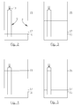
figures 2-5 disclosing a first embodiment of the present invention at different states. Only thetank 2 and flush pipe 9 are disclosed in the figures and the other elements of thepump station 1 are removed for sake of simplicity. In the first embodiment thelower opening 10 of the flush pipe 9 is located below the pump stopliquid level 16 of thetank 2, and thevalve 13 is constituted by a controllable valve. The valve shall be constituted by a solenoid valve or another controllable valve having on/off operational characteristic. According to a preferred embodiment the controllable valve shall be biased towards the open state, and when the controllable valve is activated the valve is closed. Thereto the flush pipe 9 may comprise a check valve (non-return valve) as a safety measure if the controllable valve should get stuck in the closed state. The operation of the flush pipe 9 according to the first embodiment will now be described by means of the schematic disclosures infigures 2-5 . - In
figure 2 thepump 6 has just been stopped and the liquid level in thetank 2 is located at the pump stopliquid level 16, and thevalve 13 is in the open state. - In
figure 3 thetank 2 is refilled and thevalve 13 is kept in the open state such that the air in themain body 12 can escape through theupper opening 11 via theopen valve 13. Thereby themain body 12 of the flush pipe 9 is automatically primed/filled with liquid simultaneously as the liquid level in thetank 2 increase/rise. According to an alternative embodiment thevalve 13 is kept closed when the liquid level in thetank 2 rises, and then thevalve 13 is opened before or at the same time as the liquid level in thetank 2 has reached the pump startliquid level 15 in order to prime the flush pipe 9 with liquid. - In
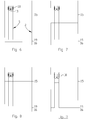
figure 4 the liquid level in thetank 2 has reached the pump startliquid level 15 and the flush pipe 9 is primed and the state of thevalve 13 is changed from open to closed. Thepump 6 is activated and when thepump 6 is active and discharge liquid from thetank 2 the liquid level in thetank 2 drops, but the liquid volume in themain body 12 of the flush pipe 9 is remained due to theclosed valve 13. - In
figure 5 thepump 6 is still active and the liquid level in thetank 2 has dropped to the valveopen liquid level 17. The valveopen liquid level 17 is located above the pump stopliquid level 16. The state of thevalve 13 is then changed from closed to open, whereby the liquid volume in themain body 12 of the flush pipe 9 will rush down into thetank 2 and mix/circulate the liquid in thetank 2. Thepump 6 is still active during the mixing/circulation and continues to discharge liquid until the liquid level in thetank 2 drops to the pump stopliquid level 16, as disclosed infigure 2 . - It shall be pointed out that the flush pipe 9 can be released each cycle, every second cycle, etc. based on the average/ordinary nature of the influent liquid entering the
pump station 1. According to another (not disclosed) embodiment the flush pipe 9 can be partly released by opening thevalve 13 when the liquid level in thetank 2 is for instance half way between the pump startliquid level 15 and the valveopen liquid level 17, and then close thevalve 13. Thereby half the liquid volume in the flush pipe 9 is used, and the remaining part of the liquid volume in the flush pipe 9 is released when the liquid level in thetank 2 drops to the valveopen liquid level 17. - Reference is now made to
figures 6-9 disclosing a second embodiment of the present invention at different states. Only thetank 2 and flush pipe 9 are disclosed in the figures and the other elements of thepump station 1 are removed for sake of simplicity. In the second embodiment thelower opening 10 of the flush pipe 9 is located above the pump stopliquid level 16 of thetank 2, and thevalve 13 is constituted by a mechanical check valve (non-return valve). The mechanical check valve is configured to admit fluid flow in the direction from thelower opening 10 towards theupper opening 11 of the flush pipe 9. According to a preferred embodiment the mechanical check valve is constituted by a hinged plate abutting and sealing theupper opening 11 of the flush pipe 9. The operation of the flush pipe 9 according to the second embodiment will now be described by means of the schematic disclosures infigures 6-9 . According to the disclosed second embodiment the flush pipe 9 is suspended in aspring assembly 18 comprising at least one spring, said spring preferably being a helical tension spring. - In
figure 6 thepump 6 has just been stopped and the liquid level in thetank 2 is located at the pump stopliquid level 16. - In
figure 7 thetank 2 is refilled and thevalve 13 is in the open state such that the air in themain body 12 can escape through theupper opening 11 via thevalve 13. Thereby themain body 12 of the flush pipe 9 is automatically primed/filled with liquid simultaneously as the liquid level in thetank 2 increase/rise. - In
figure 8 the liquid level in thetank 2 has reached the pump startliquid level 15 and the flush pipe 9 is primed and the state of thevalve 13 is automatically changed from open to closed. Thepump 6 is activated and when thepump 6 is active and discharge liquid from thetank 2 the liquid level in the tank drops, but the liquid volume in themain body 12 of the flush pipe 9 is remained. - When the
pump 6 is active and the liquid level in thetank 2 drops, the weight of the liquid volume in the flush pipe 9 that is located above the liquid level in thetank 2 will put tension to thespring assembly 18 and the flush pipe 9 will move downwards from the initial position to a lowermost position. The lowermost position of the flush pipe 9 is preferably equal to or more than 10 centimeters below the initial position, i.e. when the flush pipe 9 is empty. The lowermost position of the flush pipe 9 is preferably equal to or less than 20 centimeters below the initial position. - In
figure 9 thepump 6 is active and the liquid level in thetank 2 has dropped to aflush liquid level 19. Theflush liquid level 19 is at the same height in thetank 2 as thelower opening 10 of the flush pipe 9 when the flush pipe 9 is in the lowermost position. Thereby, air will start to enter into themain body 12 of the flush pipe 9 via thelower opening 10 such that the liquid volume in themain body 12 of the flush pipe 9 starts to rush down into thetank 2 and mix/circulate the liquid in thetank 2. Thevalve 13 is still closed. When the liquid volume of the flush pipe 9 is emptied into thetank 2 the liquid level in thetank 2 will rise, but simultaneously the weight of the instantaneously remaining liquid volume in the flush pipe 9 will decrease and the flush pipe 9 is pulled upwards by thespring assembly 18, such that the when the liquid in the flush pipe 9 starts to enter thetank 2 thelower opening 10 of the flush pipe 9 is kept above the instantaneous liquid level in thetank 2. Thus, the upwards movement of the flush pipe 9 compensates for the rising liquid level in thetank 2. If this is not the case, the time for emptying the flush pipe 9 will be too long as the lower opening of the flush pipe is then alternately below and above the liquid level in the tank. Thepump 6 is still active during the emptying of the flush pipe 9 and continues to discharge liquid until the flush pipe 9 is empty of liquid and the liquid level in thetank 2 drops to the pump stopliquid level 16, as disclosed infigure 6 . - According to an alternative embodiment (not disclosed) the flush pipe 9 is suspended in an articulated manner in the upper portion of the flush pipe 9, preferably some distance from the upper end of the flush pipe 9. When the liquid level in the
tank 2 reaches theflush liquid level 19 and air starts to enter the flush pipe 9, the turbulence/chaos/waves at the liquid level in thetank 2 will create forces rendering the flush pipe 9 to swing back and forth which will help to empty the flush pipe 9 in short enough time. - The invention is not limited only to the embodiments described above and shown in the drawings, which primarily have an illustrative and exemplifying purpose. This patent application is intended to cover all adjustments and variants of the preferred embodiments described herein, thus the present invention is defined by the wording of the appended claims and thus, the equipment may be modified in all kinds of ways within the scope of the appended claims.
- It shall also be pointed out that all information about/concerning terms such as above, under, upper, lower, etc., shall be interpreted/read having the equipment oriented according to the figures, having the drawings oriented such that the references can be properly read. Thus, such terms only indicates mutual relations in the shown embodiments, which relations may be changed if the inventive equipment is provided with another structure/design.
- It shall also be pointed out that even thus it is not explicitly stated that features from a specific embodiment may be combined with features from another embodiment, the combination shall be considered obvious, if the combination is possible.
- Throughout this specification and the claims which follows, unless the context requires otherwise, the word "comprise", and variations such as "comprises" or "comprising", will be understood to imply the inclusion of a stated integer or steps or group of integers or steps but not the exclusion of any other integer or step or group of integers or steps.
Claims (11)
- A pump station for intermediate storage of liquid, such as wastewater, comprising a tank (2) configured to house said liquid, an inlet (5) for influent liquid flow, a pump (6) configured to intermittently discharge liquid from the tank (2) and an outlet (7) for effluent liquid flow, characterized in that the pump station (1) comprises a flush pipe (9) having a lower opening (10) provided in said tank (2) and an upper opening (11), wherein the lower opening (10) of the flush pipe (9) is located below a pump start liquid level (15) of the tank (2), and wherein the flush pipe (9) comprises a valve (13) configured to open/close fluid communication between the lower opening (10) of the flush pipe (9) and the upper opening (11) of the flush pipe (9).
- The pump station according to claim 1, wherein the valve (13) is located adjacent the upper opening (11) of the flush pipe (9).
- The pump station according to claim 1 or 2, wherein the valve (13) is located above said pump start liquid level (15) of the tank (2).
- The pump station according to any of claims 1-3, wherein the upper opening (11) of the flush pipe (9) is provided in said tank (2).
- The pump station according to any preceding claim, wherein the lower opening (10) of the flush pipe (9) is located below a pump stop liquid level (15) of the tank (2), and wherein the valve (13) is constituted by a controllable valve.
- The pump station according to any of claims 1-4, wherein the lower opening (10) of the flush pipe (9) is located above a pump stop liquid level (16) of the tank (2), and wherein the valve (13) is constituted by a mechanical check valve, wherein the mechanical check valve being configured to admit fluid flow in the direction from the lower opening (10) of the flush pipe (9) towards the upper opening (11) of the flush pipe (9).
- The pump station according to claim 6, wherein the flush pipe (9) is suspended by a spring assembly (18).
- The pump station according to any preceding claim, wherein the average cross sectional area of a main body (12) of the flush pipe (9) is equal to or more than 3 percent of the average cross sectional area of the tank (2), preferably more than 6 percent.
- The pump station according to any preceding claim, wherein the average cross sectional area of a main body (12) of the flush pipe (9) is equal to or less than 20 percent of the average cross sectional area of the tank (2), preferably less than 10 percent.
- The pump station according to any preceding claim, wherein the volume of the flush pipe (9), taken between the pump start liquid level (15) and the lower opening (10) of the flush pipe (9), is be equal to or more than 5 percent of the volume of the tank (2), taken below the valve open liquid level (17) or taken below the flush liquid level (19), preferably more than 10 percent.
- The pump station according to any preceding claim, wherein the volume of the flush pipe (9), taken between the pump start liquid level (15) and the lower opening (10) of the flush pipe (9), is be equal to or less than 30 percent of the volume of the tank (2), taken below the valve open liquid level (17) or taken below the flush liquid level (19), preferably less than 20 percent.
Priority Applications (5)
| Application Number | Priority Date | Filing Date | Title |
|---|---|---|---|
| DK16186113.3T DK3290604T3 (en) | 2016-08-29 | 2016-08-29 | Pump station |
| EP16186113.3A EP3290604B1 (en) | 2016-08-29 | 2016-08-29 | Pump station |
| US16/328,949 US10829923B2 (en) | 2016-08-29 | 2017-08-28 | Pump station comprising a flush pipe |
| CN201780053110.6A CN109844233B (en) | 2016-08-29 | 2017-08-28 | Pump station including flushing line |
| PCT/EP2017/071487 WO2018041746A1 (en) | 2016-08-29 | 2017-08-28 | Pump station comprising a flush pipe |
Applications Claiming Priority (1)
| Application Number | Priority Date | Filing Date | Title |
|---|---|---|---|
| EP16186113.3A EP3290604B1 (en) | 2016-08-29 | 2016-08-29 | Pump station |
Publications (2)
| Publication Number | Publication Date |
|---|---|
| EP3290604A1 true EP3290604A1 (en) | 2018-03-07 |
| EP3290604B1 EP3290604B1 (en) | 2021-04-21 |
Family
ID=56896348
Family Applications (1)
| Application Number | Title | Priority Date | Filing Date |
|---|---|---|---|
| EP16186113.3A Active EP3290604B1 (en) | 2016-08-29 | 2016-08-29 | Pump station |
Country Status (5)
| Country | Link |
|---|---|
| US (1) | US10829923B2 (en) |
| EP (1) | EP3290604B1 (en) |
| CN (1) | CN109844233B (en) |
| DK (1) | DK3290604T3 (en) |
| WO (1) | WO2018041746A1 (en) |
Families Citing this family (3)
| Publication number | Priority date | Publication date | Assignee | Title |
|---|---|---|---|---|
| CN112112255A (en) * | 2019-06-21 | 2020-12-22 | 宝山钢铁股份有限公司 | Draining pump control system |
| CN112196080B (en) * | 2020-09-11 | 2022-02-08 | 南京贝德环保设备制造有限公司 | Prefabricated pump station of diversified clear integration |
| CN116037590B (en) * | 2022-11-12 | 2023-08-08 | 广州全康环保设备有限公司 | Inner cavity cleaning structure for prefabricated pump station |
Citations (5)
| Publication number | Priority date | Publication date | Assignee | Title |
|---|---|---|---|---|
| EP0472509A1 (en) | 1990-08-21 | 1992-02-26 | Itt Flygt Ab | A method and a device for automatic circulation in a waste water pump station |
| DE4330838A1 (en) * | 1993-09-11 | 1995-03-16 | Fass Werner | Pumping station for liquids |
| WO2004067863A1 (en) * | 2003-01-31 | 2004-08-12 | Intermediker Kft. | Method and pump unit for the effective treatment of sewage in a transfer tank |
| EP2078792A1 (en) * | 2008-01-14 | 2009-07-15 | Oy KWH Pipe AB | Method and device for flushing a pump |
| GB2486223A (en) * | 2010-12-07 | 2012-06-13 | Hydrok Storm Systems Ltd | Storm Tank Cleansing System |
Family Cites Families (6)
| Publication number | Priority date | Publication date | Assignee | Title |
|---|---|---|---|---|
| US4013087A (en) * | 1975-03-10 | 1977-03-22 | Hanna Enterprises, Inc. | Disposal of liquid effluent from sewage treatment plants |
| EP0865547B1 (en) * | 1995-12-04 | 2000-08-09 | Jörgen Mosbaek JOHANNESSEN | A device for controlling a liquid flow in a conduit system |
| CN2348021Y (en) * | 1998-12-07 | 1999-11-10 | 许温德 | Improved structure of toilet cistern |
| CN201472706U (en) * | 2009-08-18 | 2010-05-19 | 孙小青 | Filling tube for liquid filling equipment |
| CN201635168U (en) * | 2010-01-25 | 2010-11-17 | 安徽天健水处理设备有限公司 | Basement bathroom sewage automatic lifting equipment |
| CN202073174U (en) * | 2011-04-13 | 2011-12-14 | 淮安富泰革基布有限公司 | Sewage suction device of sewage tank |
-
2016
- 2016-08-29 EP EP16186113.3A patent/EP3290604B1/en active Active
- 2016-08-29 DK DK16186113.3T patent/DK3290604T3/en active
-
2017
- 2017-08-28 CN CN201780053110.6A patent/CN109844233B/en not_active Expired - Fee Related
- 2017-08-28 US US16/328,949 patent/US10829923B2/en active Active
- 2017-08-28 WO PCT/EP2017/071487 patent/WO2018041746A1/en not_active Ceased
Patent Citations (5)
| Publication number | Priority date | Publication date | Assignee | Title |
|---|---|---|---|---|
| EP0472509A1 (en) | 1990-08-21 | 1992-02-26 | Itt Flygt Ab | A method and a device for automatic circulation in a waste water pump station |
| DE4330838A1 (en) * | 1993-09-11 | 1995-03-16 | Fass Werner | Pumping station for liquids |
| WO2004067863A1 (en) * | 2003-01-31 | 2004-08-12 | Intermediker Kft. | Method and pump unit for the effective treatment of sewage in a transfer tank |
| EP2078792A1 (en) * | 2008-01-14 | 2009-07-15 | Oy KWH Pipe AB | Method and device for flushing a pump |
| GB2486223A (en) * | 2010-12-07 | 2012-06-13 | Hydrok Storm Systems Ltd | Storm Tank Cleansing System |
Also Published As
| Publication number | Publication date |
|---|---|
| US20190242108A1 (en) | 2019-08-08 |
| EP3290604B1 (en) | 2021-04-21 |
| DK3290604T3 (en) | 2021-06-21 |
| WO2018041746A1 (en) | 2018-03-08 |
| CN109844233A (en) | 2019-06-04 |
| CN109844233B (en) | 2021-03-09 |
| US10829923B2 (en) | 2020-11-10 |
Similar Documents
| Publication | Publication Date | Title |
|---|---|---|
| US10829923B2 (en) | Pump station comprising a flush pipe | |
| EP1697049B1 (en) | Grease separator for kitchen sinks and other applications | |
| KR101911497B1 (en) | Non-electric water immersion prevention device | |
| US20190226192A1 (en) | Storm drainage detention assembly and system | |
| JP7812156B2 (en) | Solid-liquid separation system | |
| JP5827184B2 (en) | Trap siphon drainage device | |
| AU2018239819A1 (en) | Arrangement for accumulation and evacuation of defrosting and condensation water from refrigeration and cooling units | |
| JP6949470B2 (en) | Offensive odor prevention type drainage system | |
| JP4730603B2 (en) | Recharge method and groundwater recharge system used therefor | |
| US20040016695A1 (en) | Radial flow septic tank | |
| US9205353B2 (en) | Scum removal system for liquids | |
| US6053206A (en) | Device for controlling a liquid flow in a conduit system | |
| JP2024028319A (en) | Driving method of solid-liquid separator | |
| WO2015159203A1 (en) | Waste water pump lying dry in a liquid tight insert which can be removably lowered into a sump | |
| KR200439029Y1 (en) | Sedimentation Separators of Sedimentation Bottom Separation and Fluid Swirl Flow Types | |
| EP2345766A1 (en) | Waste liquid tank | |
| JP4948517B2 (en) | Siphon drainage | |
| RU204895U1 (en) | Fuse separator with anti-settling function | |
| JP7730194B2 (en) | Solid-liquid separator | |
| US20050121078A1 (en) | Automatic dosing pressure chamber distribution of effluent | |
| JP2021154253A (en) | Transfer system | |
| JP2025180647A (en) | Transfer device and transfer method for transfer device | |
| JP2017089995A (en) | Automatic drainage device and drainage method | |
| US872076A (en) | Alternating siphon. | |
| US601742A (en) | Sewer construction |
Legal Events
| Date | Code | Title | Description |
|---|---|---|---|
| PUAI | Public reference made under article 153(3) epc to a published international application that has entered the european phase |
Free format text: ORIGINAL CODE: 0009012 |
|
| STAA | Information on the status of an ep patent application or granted ep patent |
Free format text: STATUS: THE APPLICATION HAS BEEN PUBLISHED |
|
| AK | Designated contracting states |
Kind code of ref document: A1 Designated state(s): AL AT BE BG CH CY CZ DE DK EE ES FI FR GB GR HR HU IE IS IT LI LT LU LV MC MK MT NL NO PL PT RO RS SE SI SK SM TR |
|
| AX | Request for extension of the european patent |
Extension state: BA ME |
|
| STAA | Information on the status of an ep patent application or granted ep patent |
Free format text: STATUS: REQUEST FOR EXAMINATION WAS MADE |
|
| 17P | Request for examination filed |
Effective date: 20180904 |
|
| RBV | Designated contracting states (corrected) |
Designated state(s): AL AT BE BG CH CY CZ DE DK EE ES FI FR GB GR HR HU IE IS IT LI LT LU LV MC MK MT NL NO PL PT RO RS SE SI SK SM TR |
|
| RAP1 | Party data changed (applicant data changed or rights of an application transferred) |
Owner name: XYLEM EUROPE GMBH |
|
| STAA | Information on the status of an ep patent application or granted ep patent |
Free format text: STATUS: EXAMINATION IS IN PROGRESS |
|
| 17Q | First examination report despatched |
Effective date: 20200309 |
|
| GRAP | Despatch of communication of intention to grant a patent |
Free format text: ORIGINAL CODE: EPIDOSNIGR1 |
|
| STAA | Information on the status of an ep patent application or granted ep patent |
Free format text: STATUS: GRANT OF PATENT IS INTENDED |
|
| INTG | Intention to grant announced |
Effective date: 20201127 |
|
| RIN1 | Information on inventor provided before grant (corrected) |
Inventor name: NORDEMO, STEFAN |
|
| GRAS | Grant fee paid |
Free format text: ORIGINAL CODE: EPIDOSNIGR3 |
|
| GRAA | (expected) grant |
Free format text: ORIGINAL CODE: 0009210 |
|
| STAA | Information on the status of an ep patent application or granted ep patent |
Free format text: STATUS: THE PATENT HAS BEEN GRANTED |
|
| AK | Designated contracting states |
Kind code of ref document: B1 Designated state(s): AL AT BE BG CH CY CZ DE DK EE ES FI FR GB GR HR HU IE IS IT LI LT LU LV MC MK MT NL NO PL PT RO RS SE SI SK SM TR |
|
| REG | Reference to a national code |
Ref country code: GB Ref legal event code: FG4D |
|
| REG | Reference to a national code |
Ref country code: CH Ref legal event code: EP |
|
| REG | Reference to a national code |
Ref country code: DE Ref legal event code: R096 Ref document number: 602016056373 Country of ref document: DE |
|
| REG | Reference to a national code |
Ref country code: IE Ref legal event code: FG4D |
|
| REG | Reference to a national code |
Ref country code: AT Ref legal event code: REF Ref document number: 1384776 Country of ref document: AT Kind code of ref document: T Effective date: 20210515 |
|
| REG | Reference to a national code |
Ref country code: DK Ref legal event code: T3 Effective date: 20210617 |
|
| REG | Reference to a national code |
Ref country code: NO Ref legal event code: T2 Effective date: 20210421 |
|
| REG | Reference to a national code |
Ref country code: SE Ref legal event code: TRGR |
|
| REG | Reference to a national code |
Ref country code: LT Ref legal event code: MG9D |
|
| REG | Reference to a national code |
Ref country code: AT Ref legal event code: MK05 Ref document number: 1384776 Country of ref document: AT Kind code of ref document: T Effective date: 20210421 |
|
| REG | Reference to a national code |
Ref country code: NL Ref legal event code: MP Effective date: 20210421 |
|
| PG25 | Lapsed in a contracting state [announced via postgrant information from national office to epo] |
Ref country code: NL Free format text: LAPSE BECAUSE OF FAILURE TO SUBMIT A TRANSLATION OF THE DESCRIPTION OR TO PAY THE FEE WITHIN THE PRESCRIBED TIME-LIMIT Effective date: 20210421 Ref country code: LT Free format text: LAPSE BECAUSE OF FAILURE TO SUBMIT A TRANSLATION OF THE DESCRIPTION OR TO PAY THE FEE WITHIN THE PRESCRIBED TIME-LIMIT Effective date: 20210421 Ref country code: FI Free format text: LAPSE BECAUSE OF FAILURE TO SUBMIT A TRANSLATION OF THE DESCRIPTION OR TO PAY THE FEE WITHIN THE PRESCRIBED TIME-LIMIT Effective date: 20210421 Ref country code: HR Free format text: LAPSE BECAUSE OF FAILURE TO SUBMIT A TRANSLATION OF THE DESCRIPTION OR TO PAY THE FEE WITHIN THE PRESCRIBED TIME-LIMIT Effective date: 20210421 Ref country code: AT Free format text: LAPSE BECAUSE OF FAILURE TO SUBMIT A TRANSLATION OF THE DESCRIPTION OR TO PAY THE FEE WITHIN THE PRESCRIBED TIME-LIMIT Effective date: 20210421 Ref country code: BG Free format text: LAPSE BECAUSE OF FAILURE TO SUBMIT A TRANSLATION OF THE DESCRIPTION OR TO PAY THE FEE WITHIN THE PRESCRIBED TIME-LIMIT Effective date: 20210721 |
|
| PG25 | Lapsed in a contracting state [announced via postgrant information from national office to epo] |
Ref country code: PT Free format text: LAPSE BECAUSE OF FAILURE TO SUBMIT A TRANSLATION OF THE DESCRIPTION OR TO PAY THE FEE WITHIN THE PRESCRIBED TIME-LIMIT Effective date: 20210823 Ref country code: PL Free format text: LAPSE BECAUSE OF FAILURE TO SUBMIT A TRANSLATION OF THE DESCRIPTION OR TO PAY THE FEE WITHIN THE PRESCRIBED TIME-LIMIT Effective date: 20210421 Ref country code: RS Free format text: LAPSE BECAUSE OF FAILURE TO SUBMIT A TRANSLATION OF THE DESCRIPTION OR TO PAY THE FEE WITHIN THE PRESCRIBED TIME-LIMIT Effective date: 20210421 Ref country code: GR Free format text: LAPSE BECAUSE OF FAILURE TO SUBMIT A TRANSLATION OF THE DESCRIPTION OR TO PAY THE FEE WITHIN THE PRESCRIBED TIME-LIMIT Effective date: 20210722 Ref country code: IS Free format text: LAPSE BECAUSE OF FAILURE TO SUBMIT A TRANSLATION OF THE DESCRIPTION OR TO PAY THE FEE WITHIN THE PRESCRIBED TIME-LIMIT Effective date: 20210821 Ref country code: LV Free format text: LAPSE BECAUSE OF FAILURE TO SUBMIT A TRANSLATION OF THE DESCRIPTION OR TO PAY THE FEE WITHIN THE PRESCRIBED TIME-LIMIT Effective date: 20210421 |
|
| REG | Reference to a national code |
Ref country code: DE Ref legal event code: R097 Ref document number: 602016056373 Country of ref document: DE |
|
| PG25 | Lapsed in a contracting state [announced via postgrant information from national office to epo] |
Ref country code: SK Free format text: LAPSE BECAUSE OF FAILURE TO SUBMIT A TRANSLATION OF THE DESCRIPTION OR TO PAY THE FEE WITHIN THE PRESCRIBED TIME-LIMIT Effective date: 20210421 Ref country code: SM Free format text: LAPSE BECAUSE OF FAILURE TO SUBMIT A TRANSLATION OF THE DESCRIPTION OR TO PAY THE FEE WITHIN THE PRESCRIBED TIME-LIMIT Effective date: 20210421 Ref country code: CZ Free format text: LAPSE BECAUSE OF FAILURE TO SUBMIT A TRANSLATION OF THE DESCRIPTION OR TO PAY THE FEE WITHIN THE PRESCRIBED TIME-LIMIT Effective date: 20210421 Ref country code: EE Free format text: LAPSE BECAUSE OF FAILURE TO SUBMIT A TRANSLATION OF THE DESCRIPTION OR TO PAY THE FEE WITHIN THE PRESCRIBED TIME-LIMIT Effective date: 20210421 Ref country code: RO Free format text: LAPSE BECAUSE OF FAILURE TO SUBMIT A TRANSLATION OF THE DESCRIPTION OR TO PAY THE FEE WITHIN THE PRESCRIBED TIME-LIMIT Effective date: 20210421 Ref country code: ES Free format text: LAPSE BECAUSE OF FAILURE TO SUBMIT A TRANSLATION OF THE DESCRIPTION OR TO PAY THE FEE WITHIN THE PRESCRIBED TIME-LIMIT Effective date: 20210421 |
|
| PLBE | No opposition filed within time limit |
Free format text: ORIGINAL CODE: 0009261 |
|
| STAA | Information on the status of an ep patent application or granted ep patent |
Free format text: STATUS: NO OPPOSITION FILED WITHIN TIME LIMIT |
|
| 26N | No opposition filed |
Effective date: 20220124 |
|
| REG | Reference to a national code |
Ref country code: CH Ref legal event code: PL |
|
| PG25 | Lapsed in a contracting state [announced via postgrant information from national office to epo] |
Ref country code: MC Free format text: LAPSE BECAUSE OF FAILURE TO SUBMIT A TRANSLATION OF THE DESCRIPTION OR TO PAY THE FEE WITHIN THE PRESCRIBED TIME-LIMIT Effective date: 20210421 |
|
| REG | Reference to a national code |
Ref country code: BE Ref legal event code: MM Effective date: 20210831 |
|
| PG25 | Lapsed in a contracting state [announced via postgrant information from national office to epo] |
Ref country code: LI Free format text: LAPSE BECAUSE OF NON-PAYMENT OF DUE FEES Effective date: 20210831 Ref country code: CH Free format text: LAPSE BECAUSE OF NON-PAYMENT OF DUE FEES Effective date: 20210831 |
|
| PG25 | Lapsed in a contracting state [announced via postgrant information from national office to epo] |
Ref country code: IS Free format text: LAPSE BECAUSE OF FAILURE TO SUBMIT A TRANSLATION OF THE DESCRIPTION OR TO PAY THE FEE WITHIN THE PRESCRIBED TIME-LIMIT Effective date: 20210821 Ref country code: LU Free format text: LAPSE BECAUSE OF NON-PAYMENT OF DUE FEES Effective date: 20210829 Ref country code: AL Free format text: LAPSE BECAUSE OF FAILURE TO SUBMIT A TRANSLATION OF THE DESCRIPTION OR TO PAY THE FEE WITHIN THE PRESCRIBED TIME-LIMIT Effective date: 20210421 |
|
| PG25 | Lapsed in a contracting state [announced via postgrant information from national office to epo] |
Ref country code: IT Free format text: LAPSE BECAUSE OF FAILURE TO SUBMIT A TRANSLATION OF THE DESCRIPTION OR TO PAY THE FEE WITHIN THE PRESCRIBED TIME-LIMIT Effective date: 20210421 Ref country code: IE Free format text: LAPSE BECAUSE OF NON-PAYMENT OF DUE FEES Effective date: 20210829 Ref country code: BE Free format text: LAPSE BECAUSE OF NON-PAYMENT OF DUE FEES Effective date: 20210831 |
|
| PG25 | Lapsed in a contracting state [announced via postgrant information from national office to epo] |
Ref country code: HU Free format text: LAPSE BECAUSE OF FAILURE TO SUBMIT A TRANSLATION OF THE DESCRIPTION OR TO PAY THE FEE WITHIN THE PRESCRIBED TIME-LIMIT; INVALID AB INITIO Effective date: 20160829 |
|
| PG25 | Lapsed in a contracting state [announced via postgrant information from national office to epo] |
Ref country code: CY Free format text: LAPSE BECAUSE OF FAILURE TO SUBMIT A TRANSLATION OF THE DESCRIPTION OR TO PAY THE FEE WITHIN THE PRESCRIBED TIME-LIMIT Effective date: 20210421 |
|
| PG25 | Lapsed in a contracting state [announced via postgrant information from national office to epo] |
Ref country code: MK Free format text: LAPSE BECAUSE OF FAILURE TO SUBMIT A TRANSLATION OF THE DESCRIPTION OR TO PAY THE FEE WITHIN THE PRESCRIBED TIME-LIMIT Effective date: 20210421 |
|
| PG25 | Lapsed in a contracting state [announced via postgrant information from national office to epo] |
Ref country code: MT Free format text: LAPSE BECAUSE OF FAILURE TO SUBMIT A TRANSLATION OF THE DESCRIPTION OR TO PAY THE FEE WITHIN THE PRESCRIBED TIME-LIMIT Effective date: 20210421 |
|
| PGFP | Annual fee paid to national office [announced via postgrant information from national office to epo] |
Ref country code: GB Payment date: 20240827 Year of fee payment: 9 |
|
| PGFP | Annual fee paid to national office [announced via postgrant information from national office to epo] |
Ref country code: NO Payment date: 20240828 Year of fee payment: 9 |
|
| PGFP | Annual fee paid to national office [announced via postgrant information from national office to epo] |
Ref country code: DK Payment date: 20250825 Year of fee payment: 10 Ref country code: DE Payment date: 20250827 Year of fee payment: 10 |
|
| PGFP | Annual fee paid to national office [announced via postgrant information from national office to epo] |
Ref country code: FR Payment date: 20250825 Year of fee payment: 10 |
|
| PGFP | Annual fee paid to national office [announced via postgrant information from national office to epo] |
Ref country code: SE Payment date: 20250827 Year of fee payment: 10 |
|
| PG25 | Lapsed in a contracting state [announced via postgrant information from national office to epo] |
Ref country code: TR Free format text: LAPSE BECAUSE OF FAILURE TO SUBMIT A TRANSLATION OF THE DESCRIPTION OR TO PAY THE FEE WITHIN THE PRESCRIBED TIME-LIMIT Effective date: 20210421 |
|
| PG25 | Lapsed in a contracting state [announced via postgrant information from national office to epo] |
Ref country code: NO Free format text: LAPSE BECAUSE OF NON-PAYMENT OF DUE FEES Effective date: 20250831 |
|
| GBPC | Gb: european patent ceased through non-payment of renewal fee |
Effective date: 20250829 |
|
| PG25 | Lapsed in a contracting state [announced via postgrant information from national office to epo] |
Ref country code: GB Free format text: LAPSE BECAUSE OF NON-PAYMENT OF DUE FEES Effective date: 20250829 |