EP3290295A2 - Hydraulic bi-directional flow switches - Google Patents
Hydraulic bi-directional flow switches Download PDFInfo
- Publication number
- EP3290295A2 EP3290295A2 EP17184223.0A EP17184223A EP3290295A2 EP 3290295 A2 EP3290295 A2 EP 3290295A2 EP 17184223 A EP17184223 A EP 17184223A EP 3290295 A2 EP3290295 A2 EP 3290295A2
- Authority
- EP
- European Patent Office
- Prior art keywords
- fluid
- piston
- steering
- hydraulic
- hydraulic steering
- Prior art date
- Legal status (The legal status is an assumption and is not a legal conclusion. Google has not performed a legal analysis and makes no representation as to the accuracy of the status listed.)
- Granted
Links
Images




Classifications
-
- B—PERFORMING OPERATIONS; TRANSPORTING
- B62—LAND VEHICLES FOR TRAVELLING OTHERWISE THAN ON RAILS
- B62D—MOTOR VEHICLES; TRAILERS
- B62D3/00—Steering gears
- B62D3/14—Steering gears hydraulic
-
- B—PERFORMING OPERATIONS; TRANSPORTING
- B62—LAND VEHICLES FOR TRAVELLING OTHERWISE THAN ON RAILS
- B62D—MOTOR VEHICLES; TRAILERS
- B62D1/00—Steering controls, i.e. means for initiating a change of direction of the vehicle
- B62D1/24—Steering controls, i.e. means for initiating a change of direction of the vehicle not vehicle-mounted
- B62D1/28—Steering controls, i.e. means for initiating a change of direction of the vehicle not vehicle-mounted non-mechanical, e.g. following a line or other known markers
- B62D1/286—Systems for interrupting non-mechanical steering due to driver intervention
-
- B—PERFORMING OPERATIONS; TRANSPORTING
- B62—LAND VEHICLES FOR TRAVELLING OTHERWISE THAN ON RAILS
- B62D—MOTOR VEHICLES; TRAILERS
- B62D5/00—Power-assisted or power-driven steering
- B62D5/06—Power-assisted or power-driven steering fluid, i.e. using a pressurised fluid for most or all the force required for steering a vehicle
- B62D5/062—Details, component parts
-
- F—MECHANICAL ENGINEERING; LIGHTING; HEATING; WEAPONS; BLASTING
- F15—FLUID-PRESSURE ACTUATORS; HYDRAULICS OR PNEUMATICS IN GENERAL
- F15B—SYSTEMS ACTING BY MEANS OF FLUIDS IN GENERAL; FLUID-PRESSURE ACTUATORS, e.g. SERVOMOTORS; DETAILS OF FLUID-PRESSURE SYSTEMS, NOT OTHERWISE PROVIDED FOR
- F15B15/00—Fluid-actuated devices for displacing a member from one position to another; Gearing associated therewith
- F15B15/08—Characterised by the construction of the motor unit
- F15B15/14—Characterised by the construction of the motor unit of the straight-cylinder type
- F15B15/149—Fluid interconnections, e.g. fluid connectors, passages
-
- F—MECHANICAL ENGINEERING; LIGHTING; HEATING; WEAPONS; BLASTING
- F16—ENGINEERING ELEMENTS AND UNITS; GENERAL MEASURES FOR PRODUCING AND MAINTAINING EFFECTIVE FUNCTIONING OF MACHINES OR INSTALLATIONS; THERMAL INSULATION IN GENERAL
- F16K—VALVES; TAPS; COCKS; ACTUATING-FLOATS; DEVICES FOR VENTING OR AERATING
- F16K31/00—Actuating devices; Operating means; Releasing devices
- F16K31/12—Actuating devices; Operating means; Releasing devices actuated by fluid
- F16K31/122—Actuating devices; Operating means; Releasing devices actuated by fluid the fluid acting on a piston
-
- F—MECHANICAL ENGINEERING; LIGHTING; HEATING; WEAPONS; BLASTING
- F16—ENGINEERING ELEMENTS AND UNITS; GENERAL MEASURES FOR PRODUCING AND MAINTAINING EFFECTIVE FUNCTIONING OF MACHINES OR INSTALLATIONS; THERMAL INSULATION IN GENERAL
- F16K—VALVES; TAPS; COCKS; ACTUATING-FLOATS; DEVICES FOR VENTING OR AERATING
- F16K37/00—Special means in or on valves or other cut-off apparatus for indicating or recording operation thereof, or for enabling an alarm to be given
- F16K37/0025—Electrical or magnetic means
- F16K37/0041—Electrical or magnetic means for measuring valve parameters
-
- F—MECHANICAL ENGINEERING; LIGHTING; HEATING; WEAPONS; BLASTING
- F15—FLUID-PRESSURE ACTUATORS; HYDRAULICS OR PNEUMATICS IN GENERAL
- F15B—SYSTEMS ACTING BY MEANS OF FLUIDS IN GENERAL; FLUID-PRESSURE ACTUATORS, e.g. SERVOMOTORS; DETAILS OF FLUID-PRESSURE SYSTEMS, NOT OTHERWISE PROVIDED FOR
- F15B15/00—Fluid-actuated devices for displacing a member from one position to another; Gearing associated therewith
- F15B15/20—Other details, e.g. assembly with regulating devices
- F15B15/28—Means for indicating the position, e.g. end of stroke
- F15B15/2815—Position sensing, i.e. means for continuous measurement of position, e.g. LVDT
- F15B15/2861—Position sensing, i.e. means for continuous measurement of position, e.g. LVDT using magnetic means
-
- H—ELECTRICITY
- H01—ELECTRIC ELEMENTS
- H01H—ELECTRIC SWITCHES; RELAYS; SELECTORS; EMERGENCY PROTECTIVE DEVICES
- H01H36/00—Switches actuated by change of magnetic field or of electric field, e.g. by change of relative position of magnet and switch, by shielding
- H01H36/0006—Permanent magnet actuating reed switches
- H01H36/0013—Permanent magnet actuating reed switches characterised by the co-operation between reed switch and permanent magnet; Magnetic circuits
- H01H36/002—Actuation by moving ferromagnetic material, switch and magnet being fixed
Definitions
- This disclosure relates generally to hydraulic steering systems, and more particularly, to hydraulic bi-directional flow switches.
- Automated steering systems used in working machines such as tractors, combines or forage harvesters, for example, utilize sensors (e.g., visual sensors, pressure sensors, movement sensors, etc.) to detect when a user has engaged controls.
- sensors e.g., visual sensors, pressure sensors, movement sensors, etc.
- Such automated steering systems control flow of hydraulic fluid through a hydraulic steering system that can be disengaged when a user turns a steering wheel to manually control the steering, for example. By doing so, the user takes control of the hydraulic steering system.
- Automated steering systems are disengaged so that the user can correct movement of a working machine and/or take control of the working machine (e.g., to return the working machine to storage, etc.).
- some known automated steering systems use a flow meter to detect movement of the steering wheel.
- flow meters can be used to detect a movement of hydraulic fluid through a hydraulic steering system.
- Other known systems use external detection sensors and/or pressure/force sensors to determine whether the user has moved and/or directed the steering wheel.
- These known systems typically have a relatively high cost and associated complexity (e.g., additional electronics, system integration and/or software) to implement these sensors.
- An example apparatus includes a piston disposed in a fluid channel that is between a first fluid connection and a second fluid connection, where the first and second fluid connections define a fluid pathway for hydraulic steering fluid.
- the example apparatus also includes a detector to detect a movement of the piston away from a default position of the piston, where the piston is to displace from the default position when the hydraulic steering fluid flows along the fluid pathway.
- any part is in any way positioned on (e.g., positioned on, located on, disposed on, or formed on, etc.) another part, means that the referenced part is either in contact with the other part, or that the referenced part is above the other part with one or more intermediate part(s) located therebetween. Stating that any part is in contact with another part means that there is no intermediate part between the two parts.
- Hydraulic bi-directional flow switches are disclosed herein.
- Known automated steering system typically disengage once a user moves a steering wheel.
- some known systems include a flow meter that may be used to detect a movement and/or flow of hydraulic fluid through a hydraulic steering system.
- Other known systems use external detection sensors and/or pressure/force sensors to determine whether a user has moved and/or directed the steering wheel.
- These known systems typically have a relatively high cost and associated complexity to implement.
- these known systems may rely on sensor placement or additional hardware and/or software (e.g., additional associated electronics and/or programming) required to detect a user moving/rotating a steering wheel.
- the examples disclosed herein enable reliable and cost-effective detection of user input applied to a steering wheel (e.g., a user engaging and moving a steering wheel).
- the examples disclosed herein utilize detection of a movement and/or displacement of a piston that is in fluid communication with hydraulic fluid of a hydraulic steering system so that an automated steering system may be dis-engaged, for example.
- the examples disclosed herein also enable detection of flow under relatively high pressure, in which many flow meters may not be able to withstand.
- the aforementioned piston is disposed between a steering valve connection and a steering cylinder connection, and centered into a default position based on the hydraulic fluid.
- the piston is spring-loaded and/or partially moved by a spring into its respective default position (e.g., centered position).
- a magnetic sensor is used to determine a change in magnetic field (e.g., from a magnet) based on movement of the piston.
- the piston is guided by a guide rod.
- the piston has a detection portion (e.g., a wider portion) and/or an attachment (e.g., an attached part) to be detected by a magnetic field sensor.
- FIG. 1 is an example working machine 100 in which the examples disclosed herein may be implemented.
- the working machine 100 of the illustrated example includes a cab 102, tires 104, a steering system 106, and a working implement (e.g., a harvester portion) 108.
- the working machine 100 is a tractor.
- the working machine 100 of the illustrated example may be directed by an automated steering system (e.g., a visually guided steering system).
- manual control may be dis-engaged while the working machine 100 uses cameras, sensors and/or guidance systems such as a global positioning system (GPS) to automatically direct the steering system 106 to rotate the tires 104 while the working machine 100 drives in a forward direction, for example.
- GPS global positioning system
- the automated steering system is dis-engaged when a user moves and/or takes control of a steering wheel in the cab 102.
- FIG. 1 While the example of FIG. 1 is shown as a tractor.
- the examples disclosed herein may be applied to any appropriate vehicle, working machine and/or control system that utilizes hydraulic fluid. As a result, the examples disclosed herein may be applied to boats, automobiles, etc. or any other appropriate application(s).
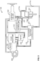
- FIG. 2 illustrates the example steering system 106 of the example working machine 100 of FIG. 1 .
- the steering system 106 of the illustrated example includes a steering column 202, a hydraulic fluid reservoir 204, a relief valve 206, a hydraulic fluid pump 208, a filter 210 and a steering cylinder 212.
- the steering system 106 also includes a first fluid supply line 214a and a second fluid supply line 214b.
- the steering system 106 also includes an automated control portion 215, which includes an automated steering hydraulic pump system 218 that is fluidly coupled to both the fluid reservoir and a junction (e.g., a fluid valve switch) 220 that interfaces with the fluid supply line 214b.
- fluid supply line 214c fluidly couples the automated steering control system 218 to the steering cylinder 212.
- an engagement controller 222 is communicatively coupled to the junction 220 as well as the automated steering hydraulic pump system 218.
- a steering wheel of the steering wheel column 202 is rotated which, in turn, causes the hydraulic fluid pump 208 to move and/or pump hydraulic fluid through the second fluid supply line 214b, thereby causing the steering cylinder 212 to displace.
- the steering system 106 is then rotated.
- the hydraulic fluid is returned to the filter 210 and the reservoir 204 via the first fluid supply line 214a.
- an additional automated hydraulic line and/or additional pump is fluidly coupled to the steering cylinder 212 (e.g., an added pump input for automated control of the steering cylinder 212).
- the automated steering system 218 of the illustrated example is directed by the engagement controller 222 to provide hydraulic fluid to the junction 220, which may function as a bypass valve between manual control from the steering color 202 or automated control from the steering system 218.
- the example automated steering system 218 receives control signals (e.g., from a navigation system, a GPS based control system, etc.) and controls an appropriate fluid flow rate and/or pressure of the hydraulic fluid is provided to the steering cylinder 212.
- the junction 220 acts as a fluid flow switch.
- FIG. 3A is a cross-sectional view of an example bi-directional flow switch (e.g., a fluid junction, a fluid connection, etc.) 300 in accordance with the teachings of this disclosure.
- the example bi-directional flow switch 300 may be implemented at the junction 220 (i.e., between the steering column 202 and the steering cylinder 212), for example. Additionally or alternatively, the bi-directional flow switch 300 (or multiple bi-directional flow switches 300) may be implemented at other portions of the steering system 106. As can be seen in the illustrated example of FIG.
- a fluid path/passageway is defined in a valve body 301 between a steering valve connection (e.g., flow path, orifice, passageway, opening etc.) 302, an automatic steering valve connection (e.g., an automated steering valve connection, an automated hydraulic input, etc.) 304, and a steering cylinder connection 306.
- the example bi-directional switch 300 also includes a piston (e.g., a flow cylinder, a hollow cylinder, etc.) 308 with a detection portion (e.g., an enlarged portion, a ring portion, etc.) 312 and an internal bore 314, a guide rod 316, springs 318 and plugs (e.g., seals, gaskets, etc.) 320.
- the example flow switch 300 also includes a proximity detection sensor 322 and a corresponding magnet 324.
- the proximity detection sensor 322 is a magnetic field sensor such as a Hall Effect sensor, for example.
- the piston 308 is at least partially composed of a magnetic/magnetized steel material. However, any appropriate material and/or magnetic material may be used.
- the valve body 301 is at least partially composed of a non-magnetic material (e.g., aluminum, brass, etc.).
- the steering valve 302 defines a first fluid connection to the steering column 202.
- the steering cylinder connection 306 defines a second fluid connection to the steering column 202
- the automatic steering valve connection 304 defines a third fluid connection to the automated steering system 218.
- hydraulic fluid flowing between the automatic steering valve connection 304 and the steering cylinder connection 306 does not significantly displace the piston 308.
- hydraulic fluid flow between the first and second fluid connections displaces the piston 308 while hydraulic fluid flow between the second and third fluid connections does not significantly displace (e.g., does not displace) the piston 308 from the default position.
- the hydraulic fluid flow effectively bypasses the piston 308 and/or a significant portion of the piston 308.
- hydraulic fluid moves between the steering valve connection (e.g., a first fluid connection) 302 and the steering cylinder connection (e.g., a second fluid connection) 304 (in either direction), thereby causing a pressure differential of the piston 308 that moves the piston 308 against the springs 318 and along the guide rod 316 in a linear movement (e.g., a linear direction).
- the piston 308 is displaced relative to the proximity detection sensor 322 as well as the magnet 324.
- the detection portion 312 of the illustrated example is also moved away from the proximity detection sensor 322.
- the piston 308 is not significantly displaced and/or displaced when hydraulic fluid flows between the automatic steering valve connection (e.g., a third fluid connection) 304 and the steering cylinder connection 306 such as during an automated hydraulic control of the steering cylinder 212.
- the automatic steering valve connection e.g., a third fluid connection
- the proximity detection sensor 322 of the illustrated example measures a change in a magnetic field (i.e., a magnetic field change) from the magnet 324 when the detection portion 312 moves away from the sensor 322 in either an downward or upward direction (in the view of FIG. 3A ) (e.g., a bi-directional movement).
- a magnetic field i.e., a magnetic field change
- fluid reservoirs and/or fluid gaps of relatively static hydraulic fluid build at ends (e.g., opposing ends) 330 of the piston 308, thereby balancing/centering the piston 308 to the default position in which the detection portion 312 is relatively close to the sensor 322 and/or the magnet 324.
- no springs 318 are used. Additionally or alternatively, the springs 318 return the piston 308 to the default position.
- the piston 308 has different magnetic properties along its length so that the proximity detection sensor 322 may determine which direction the piston 308 and/or the detection portion 312 have moved (e.g., a direction of movement) relative to the default position.
- a reed switch is used to detect movement/displacement of the piston 308.
- multiple magnetic field sensors 322 are used to determine a specific directional movement of the piston 308 (e.g., upward or downward in the view of FIG. 3A ).
- the piston 308 exhibits a magnetic field asymmetry about its default position and/or the detection portion 312 such that the magnetic field sensor 322 can determine what direction the piston 308 has displaced toward.
- the proximity detection sensor is used to determine a displacement of the piston 308 based on an expected change in a detected field associated with an overall geometry of the piston 308 (e.g., an asymmetry of a magnetic field based on the piston 308 moving away from the default and/or centered position).
- the detection portion 312 is sized and/or shaped to extend into the hydraulic fluid to facilitate movement of the piston 308 along with the hydraulic fluid flow.
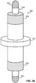
- FIG. 3B an example alternative piston-guide rod assembly is shown that includes a guide rod 338 disposed in a central opening of a piston 350.
- the piston 350 moves and/or slides along (e.g., relative to) the guide rod 338.
- the example guide rod 338 includes opposing magnetic portions 340.
- the piston 350 of the illustrated example includes the aforementioned detection portion 312 shown in FIG. 3 .
- the piston 350 includes opposing magnetic portions 352, which may be magnetized portions or assembled magnets, for example.
- the magnetic portions 340 which may be magnetized portions of the guide rod 338 or an assembled magnet, repel the piston 350 to its default centered position.
- the opposing magnetic forces caused by the magnetic portions 340 may be used to repel the piston 340 into its default position.
- the piston 350 does not have the magnetic portions 352 and the magnetic portions 340 are able to repel a material that the piston 350 is at least partially composed of (e.g., a metal material).
- FIG. 3C yet another example alternative piston-guide rod assembly is shown.
- a guide rod 360 is shown disposed within a piston 370, which moves (e.g., slides) along the guide rod 360 (e.g., is guided by the guide rod 36).
- the guide rod 360 of the illustrated example includes a groove (e.g., an annular groove) 362, in which a magnet component/assembly 364 is disposed.
- the example magnet component/assembly 364 includes a substrate 366, which may be composed of an oil-resistant and/or temperature tolerant plastic such as nylon, a fluoroplastic and/or dielectric material, etc.
- the example magnet assembly 364 also includes one or more embedded magnets 368 embedded within the substrate 366.
- the piston 370 includes the magnetic portions 352 shown in FIG. 3B .
- the piston 370 of the illustrated example also includes a magnetic detection portion 374, which may be defined by magnetizing a portion of the piston 370 and/or assembling magnetic components to the piston 370.
- a magnetic detection portion 374 may be defined by magnetizing a portion of the piston 370 and/or assembling magnetic components to the piston 370.
- the guide rod 360 as well as its associated components are shown in a partial cut view in the view of FIG. 3C .
- the opposing magnet component/assemblies 364 are used to cause a centering of the piston 370 to its default position as the piston 370 slides along and/or is guided by the guide rod 360.
- the magnet component/assemblies 364 on opposing sides of the guide rod 360 repel the respective magnetic portions 352 to center the piston 370 along a length of the guide rod 360.
- the example magnetic detection portion 374 does not extend from an outer surface of the guide rod 360.
- the magnet component/assembly 364 is disposed in a groove of the guide rod 360 that is located at or proximate a center portion of a length of the piston 370.
- the magnetic component/assembly 364 is embedded within the piston 370 (e.g., within an internal annular groove on an internal diameter of the piston 370 for detection and/or centering purposes).
- the guide rod 316 may have the magnetic detection portion 374 instead of the detection portion 312.
- any of the features described may be used on any of the examples, as appropriate.
- FIG. 4 is an example hydraulic system 400 that may be used to implement the examples disclosed herein.
- the example hydraulic steering system 400 which may be implemented in the engagement controller 222 of FIG. 2 , includes a steering control 402, which includes an automated steering controller (e.g., an automated steering controller) 404, a steering valve controller (e.g., a manual steering controller) 406 and a sensor interface 408.
- the sensor interface 408 is communicatively coupled to a magnetic sensor system 410 via a communication line 412.
- the automated steering controller 404 of the illustrated example is communicatively coupled to the automated steering control system 218 via a communication line 414.
- the steering control 402 switches between the automated steering controller 404 and the steering valve controller 406 based on whether a user has engaged the steering valve controller 406.
- the sensor interface 408 of the illustrated example utilizes the bi-directional flow switch 300 and/or the sensor 322 to determine whether the user has engaged manual control.
- the steering control 402 may engage/dis-engage the automated steering controller 404.
- the steering control 402 may disengage the steering valve controller 406.
- any appropriate positional and/or proximity sensor may be used.
- an optical detector may be used to measure displacement of the piston 308.
- a laser system may be used to detect movement/displacement of the piston 308.
- While an example manner of implementing the example hydraulic steering system of FIG. 4 is illustrated in FIG. 5 , one or more of the elements, processes and/or devices illustrated in FIG. 5 may be combined, divided, re-arranged, omitted, eliminated and/or implemented in any other way.
- the example steering control 402, the example automated steering controller 404, the example steering valve controller 406, the example sensor interface 408, the example magnetic sensor system 410 and/or, more generally, the example hydraulic steering system 400 of FIG. 4 may be implemented by hardware, software, firmware and/or any combination of hardware, software and/or firmware.
- any of the example steering control 402, the example automated steering controller 404, the example steering valve controller 406, the example sensor interface 408, the example magnetic sensor system 410 and/or, more generally, the example hydraulic steering system 400 could be implemented by one or more analog or digital circuit(s), logic circuits, programmable processor(s), application specific integrated circuit(s) (ASIC(s)), programmable logic device(s) (PLD(s)) and/or field programmable logic device(s) (FPLD(s)).
- ASIC application specific integrated circuit
- PLD programmable logic device
- FPLD field programmable logic device
- At least one of the example, steering control 402, the example automated steering controller 404, the example steering valve controller 406, the example sensor interface 408, and/or the example magnetic sensor system 410 is/are hereby expressly defined to include a tangible computer readable storage device or storage disk such as a memory, a digital versatile disk (DVD), a compact disk (CD), a Blu-ray disk, etc. storing the software and/or firmware.
- the example hydraulic steering system 400 of FIG. 4 may include one or more elements, processes and/or devices in addition to, or instead of, those illustrated in FIG. 5 , and/or may include more than one of any or all of the illustrated elements, processes and devices.
- FIG. 5 A flowchart representative of example machine readable instructions for implementing the hydraulic steering system 400 of FIG. 4 is shown in FIG. 5 .
- the machine readable instructions comprise a program for execution by a processor such as the processor 612 shown in the example processor platform 600 discussed below in connection with FIG. 6 .
- the program may be embodied in software stored on a tangible computer readable storage medium such as a CD-ROM, a floppy disk, a hard drive, a digital versatile disk (DVD), a Blu-ray disk, or a memory associated with the processor 612, but the entire program and/or parts thereof could alternatively be executed by a device other than the processor 612 and/or embodied in firmware or dedicated hardware.
- example program is described with reference to the flowchart illustrated in FIG. 5 , many other methods of implementing the example hydraulic steering system 400 may alternatively be used.
- order of execution of the blocks may be changed, and/or some of the blocks described may be changed, eliminated, or combined.
- the example process of FIG. 5 may be implemented using coded instructions (e.g., computer and/or machine readable instructions) stored on a tangible computer readable storage medium such as a hard disk drive, a flash memory, a read-only memory (ROM), a compact disk (CD), a digital versatile disk (DVD), a cache, a random-access memory (RAM) and/or any other storage device or storage disk in which information is stored for any duration (e.g., for extended time periods, permanently, for brief instances, for temporarily buffering, and/or for caching of the information).
- a tangible computer readable storage medium is expressly defined to include any type of computer readable storage device and/or storage disk and to exclude propagating signals and to exclude transmission media.
- tangible computer readable storage medium and “tangible machine readable storage medium” are used interchangeably. Additionally or alternatively, the example process of FIG. 5 may be implemented using coded instructions (e.g., computer and/or machine readable instructions) stored on a non-transitory computer and/or machine readable medium such as a hard disk drive, a flash memory, a read-only memory, a compact disk, a digital versatile disk, a cache, a random-access memory and/or any other storage device or storage disk in which information is stored for any duration (e.g., for extended time periods, permanently, for brief instances, for temporarily buffering, and/or for caching of the information).
- coded instructions e.g., computer and/or machine readable instructions
- a non-transitory computer and/or machine readable medium such as a hard disk drive, a flash memory, a read-only memory, a compact disk, a digital versatile disk, a cache, a random-access memory and/or any other storage device or storage disk in which information is
- non-transitory computer readable medium is expressly defined to include any type of computer readable storage device and/or storage disk and to exclude propagating signals and to exclude transmission media.
- phrase "at least" is used as the transition term in a preamble of a claim, it is open-ended in the same manner as the term “comprising" is open ended.
- the example method of FIG. 5 begins at block 500 where a vehicle such as the working machine 100 of FIG. 1 is being operated (block 500).
- the vehicle of the illustrated example has automated navigation (e.g., self-driving capabilities).
- the automated steering controller 404 causes hydraulic fluid to flow between the automatic steering valve connection 304 and the steering cylinder connection 306 at a controlled pressure and/or flow rate.
- an automated steering system is engaged (block 502).
- the example steering control 402 has enabled the automated steering controller 404 to direct the vehicle (e.g., based on visual sensor data and/or GPS).
- hydraulic steering valve fluid flow is detected at a bi-directional flow sensor (block 504).
- the proximity detection sensor 322 communicates with the sensor interface 408 and/or the magnetic sensor system 410 to indicate detected movement of the piston 308 away from its respective default (e.g., centered position).
- the movement of the piston 308 is caused by hydraulic fluid flowing between the steering valve connection 302 and the steering cylinder connection 306.
- control of the process returns to block 504. Otherwise, if hydraulic fluid flow is detected (block 506), the automated steering system is dis-engaged (block 508) and the process ends (block 510). In this example, the automated steering system is dis-engaged by the steering control 402 and/or the sensor interface 408.
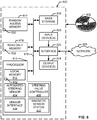
- FIG. 6 is a block diagram of an example processor platform 600 capable of executing the instructions of FIG. 5 to implement the example hydraulic steering system 400 of FIG. 4 .
- the processor platform 600 can be, for example, a server, a personal computer, a mobile device (e.g., a cell phone, a smart phone, a tablet such as an iPad TM ), a personal digital assistant (PDA), a digital video recorder, a set top box, or any other type of computing device.
- a mobile device e.g., a cell phone, a smart phone, a tablet such as an iPad TM
- PDA personal digital assistant
- a digital video recorder e.g., a digital video recorder, or any other type of computing device.
- the processor platform 600 of the illustrated example includes a processor 612.
- the processor 612 of the illustrated example is hardware.
- the processor 612 can be implemented by one or more integrated circuits, logic circuits, microprocessors or controllers from any desired family or manufacturer.
- the processor 612 of the illustrated example includes a local memory 613 (e.g., a cache).
- the processor 612 also includes the example steering control 402, the example automated steering controller 404, the example steering valve controller 406, the example sensor interface 408 and the example magnetic sensor system 410.
- the processor 612 of the illustrated example is in communication with a main memory including a volatile memory 614 and a non-volatile memory 616 via a bus 618.
- the volatile memory 614 may be implemented by Synchronous Dynamic Random Access Memory (SDRAM), Dynamic Random Access Memory (DRAM), RAMBUS Dynamic Random Access Memory (RDRAM) and/or any other type of random access memory device.
- the non-volatile memory 616 may be implemented by flash memory and/or any other desired type of memory device. Access to the main memory 614, 616 is controlled by a memory controller.
- the processor platform 600 of the illustrated example also includes an interface circuit 620.
- the interface circuit 620 may be implemented by any type of interface standard, such as an Ethernet interface, a universal serial bus (USB), and/or a PCI express interface.
- one or more input devices 622 are connected to the interface circuit 620.
- the input device(s) 622 permit(s) a user to enter data and commands into the processor 612.
- the input device(s) can be implemented by, for example, an audio sensor, a microphone, a camera (still or video), a keyboard, a button, a mouse, a touchscreen, a track-pad, a trackball, isopoint and/or a voice recognition system.
- One or more output devices 624 are also connected to the interface circuit 620 of the illustrated example.
- the output devices 624 can be implemented, for example, by display devices (e.g., a light emitting diode (LED), an organic light emitting diode (OLED), a liquid crystal display, a cathode ray tube display (CRT), a touchscreen, a tactile output device, a printer and/or speakers).
- the interface circuit 620 of the illustrated example thus, typically includes a graphics driver card, a graphics driver chip or a graphics driver processor.
- the interface circuit 620 of the illustrated example also includes a communication device such as a transmitter, a receiver, a transceiver, a modem and/or network interface card to facilitate exchange of data with external machines (e.g., computing devices of any kind) via a network 626 (e.g., an Ethernet connection, a digital subscriber line (DSL), a telephone line, coaxial cable, a cellular telephone system, etc.).
- a communication device such as a transmitter, a receiver, a transceiver, a modem and/or network interface card to facilitate exchange of data with external machines (e.g., computing devices of any kind) via a network 626 (e.g., an Ethernet connection, a digital subscriber line (DSL), a telephone line, coaxial cable, a cellular telephone system, etc.).
- DSL digital subscriber line
- the processor platform 600 of the illustrated example also includes one or more mass storage devices 628 for storing software and/or data.
- mass storage devices 628 include floppy disk drives, hard drive disks, compact disk drives, Blu-ray disk drives, RAID systems, and digital versatile disk (DVD) drives.
- the coded instructions 632 of FIG. 5 may be stored in the mass storage device 628, in the volatile memory 614, in the non-volatile memory 616, and/or on a removable tangible computer readable storage medium such as a CD or DVD.
- An example apparatus includes a piston disposed in a fluid channel that is between a first fluid connection and a second fluid connection, where the first and second fluid connections define a fluid pathway for hydraulic steering fluid.
- the example apparatus also includes a detector to detect a movement of the piston away from a default position of the piston, where the piston is to displace from the default position when the hydraulic steering fluid flows along the fluid pathway.
- An example method includes detecting movement of a piston away from a default position of the piston, where the piston is disposed in a fluid channel that fluidly couples a first fluid connection and a second fluid connection, and where hydraulic steering fluid moves between the first and second fluid connections to cause the movement of the piston.
- the example method also includes dis-engaging, based on the detected movement of the piston, an automated steering system.
- An example hydraulic steering system includes a steering valve defining a first fluid connection, a steering cylinder defining a second fluid connection, where hydraulic steering fluid moves between the first and second fluid connections.
- the example hydraulic system also includes a piston disposed in a fluid channel between the first and fluid second fluid connections.
- the piston is bi-directionally movable along a linear path when the hydraulic steering fluid flows between the first and second fluid connections.
- the example apparatus also includes a detector to detect the bi-directional movement of the piston away from a default position of the piston and a processor communicatively coupled to the detector, where the processor is to interpret the movement of the piston.
Landscapes
- Engineering & Computer Science (AREA)
- Mechanical Engineering (AREA)
- General Engineering & Computer Science (AREA)
- Chemical & Material Sciences (AREA)
- Combustion & Propulsion (AREA)
- Transportation (AREA)
- Physics & Mathematics (AREA)
- Fluid Mechanics (AREA)
- Power Steering Mechanism (AREA)
- Fluid-Pressure Circuits (AREA)
Abstract
Description
- This disclosure relates generally to hydraulic steering systems, and more particularly, to hydraulic bi-directional flow switches.
- Automated steering systems used in working machines such as tractors, combines or forage harvesters, for example, utilize sensors (e.g., visual sensors, pressure sensors, movement sensors, etc.) to detect when a user has engaged controls. Such automated steering systems control flow of hydraulic fluid through a hydraulic steering system that can be disengaged when a user turns a steering wheel to manually control the steering, for example. By doing so, the user takes control of the hydraulic steering system. Automated steering systems are disengaged so that the user can correct movement of a working machine and/or take control of the working machine (e.g., to return the working machine to storage, etc.).
- To detect whether the user has engaged the steering wheel, some known automated steering systems use a flow meter to detect movement of the steering wheel. In particular, such flow meters can be used to detect a movement of hydraulic fluid through a hydraulic steering system. Other known systems use external detection sensors and/or pressure/force sensors to determine whether the user has moved and/or directed the steering wheel. These known systems typically have a relatively high cost and associated complexity (e.g., additional electronics, system integration and/or software) to implement these sensors.
- An example apparatus includes a piston disposed in a fluid channel that is between a first fluid connection and a second fluid connection, where the first and second fluid connections define a fluid pathway for hydraulic steering fluid. The example apparatus also includes a detector to detect a movement of the piston away from a default position of the piston, where the piston is to displace from the default position when the hydraulic steering fluid flows along the fluid pathway.
- An embodiment is shown in the drawings, in which:
-
FIG. 1 is an example working machine in which the examples disclosed herein may be implemented. -
FIG. 2 is an example steering system of the example working machine ofFIG. 1 . -
FIG. 3A is a cross-sectional view of an example bi-directional flow switch in accordance with the teachings of this disclosure. -
FIGS. 3B and3C illustrate alternate piston and rod assemblies that may be implemented in the examples disclosed herein. -
FIG. 4 is an example hydraulic steering system that may be used to implement the examples disclosed herein. -
FIG. 5 is a flowchart representative of an example method that may be implemented by the example hydraulic steering system ofFIG. 4 . -
FIG. 6 is a processor platform that may be used to execute the example method ofFIG. 5 . - The Figures are not to scale. Instead, to clarify multiple layers and regions, the thickness of the layers may be enlarged in the drawings. Wherever possible, the same reference numbers will be used throughout the drawing(s) and accompanying written description to refer to the same or like parts. As used in this patent, stating that any part is in any way positioned on (e.g., positioned on, located on, disposed on, or formed on, etc.) another part, means that the referenced part is either in contact with the other part, or that the referenced part is above the other part with one or more intermediate part(s) located therebetween. Stating that any part is in contact with another part means that there is no intermediate part between the two parts.
- Hydraulic bi-directional flow switches are disclosed herein. Known automated steering system typically disengage once a user moves a steering wheel. In particular, some known systems include a flow meter that may be used to detect a movement and/or flow of hydraulic fluid through a hydraulic steering system. Other known systems use external detection sensors and/or pressure/force sensors to determine whether a user has moved and/or directed the steering wheel. These known systems typically have a relatively high cost and associated complexity to implement. In particular, these known systems may rely on sensor placement or additional hardware and/or software (e.g., additional associated electronics and/or programming) required to detect a user moving/rotating a steering wheel.
- The examples disclosed herein enable reliable and cost-effective detection of user input applied to a steering wheel (e.g., a user engaging and moving a steering wheel). In particular, the examples disclosed herein utilize detection of a movement and/or displacement of a piston that is in fluid communication with hydraulic fluid of a hydraulic steering system so that an automated steering system may be dis-engaged, for example. As a result of utilizing the hydraulic fluid for detection, the examples disclosed herein also enable detection of flow under relatively high pressure, in which many flow meters may not be able to withstand.
- In some examples, the aforementioned piston is disposed between a steering valve connection and a steering cylinder connection, and centered into a default position based on the hydraulic fluid. In some examples, the piston is spring-loaded and/or partially moved by a spring into its respective default position (e.g., centered position). In some examples, a magnetic sensor is used to determine a change in magnetic field (e.g., from a magnet) based on movement of the piston. In some examples, the piston is guided by a guide rod. In some examples, the piston has a detection portion (e.g., a wider portion) and/or an attachment (e.g., an attached part) to be detected by a magnetic field sensor.
-
FIG. 1 is anexample working machine 100 in which the examples disclosed herein may be implemented. Theworking machine 100 of the illustrated example includes acab 102,tires 104, asteering system 106, and a working implement (e.g., a harvester portion) 108. In this example, theworking machine 100 is a tractor. - In operation, the
working machine 100 of the illustrated example may be directed by an automated steering system (e.g., a visually guided steering system). In particular, manual control may be dis-engaged while theworking machine 100 uses cameras, sensors and/or guidance systems such as a global positioning system (GPS) to automatically direct thesteering system 106 to rotate thetires 104 while theworking machine 100 drives in a forward direction, for example. In this example, the automated steering system is dis-engaged when a user moves and/or takes control of a steering wheel in thecab 102. - While the example of
FIG. 1 is shown as a tractor. The examples disclosed herein may be applied to any appropriate vehicle, working machine and/or control system that utilizes hydraulic fluid. As a result, the examples disclosed herein may be applied to boats, automobiles, etc. or any other appropriate application(s). -
FIG. 2 illustrates theexample steering system 106 of theexample working machine 100 ofFIG. 1 . Thesteering system 106 of the illustrated example includes asteering column 202, ahydraulic fluid reservoir 204, arelief valve 206, ahydraulic fluid pump 208, afilter 210 and asteering cylinder 212. According to the illustrated example, thesteering system 106 also includes a firstfluid supply line 214a and a secondfluid supply line 214b. In this example, thesteering system 106 also includes anautomated control portion 215, which includes an automated steeringhydraulic pump system 218 that is fluidly coupled to both the fluid reservoir and a junction (e.g., a fluid valve switch) 220 that interfaces with thefluid supply line 214b. In addition,fluid supply line 214c fluidly couples the automatedsteering control system 218 to thesteering cylinder 212. In this example, anengagement controller 222 is communicatively coupled to thejunction 220 as well as the automated steeringhydraulic pump system 218. - To direct movement of the
steering cylinder 212 by moving/rotating thesteering system 106 described above in connection withFIG. 1 , a steering wheel of thesteering wheel column 202 is rotated which, in turn, causes thehydraulic fluid pump 208 to move and/or pump hydraulic fluid through the secondfluid supply line 214b, thereby causing thesteering cylinder 212 to displace. As a result, thesteering system 106 is then rotated. In this example, the hydraulic fluid is returned to thefilter 210 and thereservoir 204 via the firstfluid supply line 214a. In some examples, an additional automated hydraulic line and/or additional pump is fluidly coupled to the steering cylinder 212 (e.g., an added pump input for automated control of the steering cylinder 212). - To allow automated control of the
steering cylinder 212, theautomated steering system 218 of the illustrated example is directed by theengagement controller 222 to provide hydraulic fluid to thejunction 220, which may function as a bypass valve between manual control from thesteering color 202 or automated control from thesteering system 218. In particular, the exampleautomated steering system 218 receives control signals (e.g., from a navigation system, a GPS based control system, etc.) and controls an appropriate fluid flow rate and/or pressure of the hydraulic fluid is provided to thesteering cylinder 212. As a result, thejunction 220 acts as a fluid flow switch. -
FIG. 3A is a cross-sectional view of an example bi-directional flow switch (e.g., a fluid junction, a fluid connection, etc.) 300 in accordance with the teachings of this disclosure. The examplebi-directional flow switch 300 may be implemented at the junction 220 (i.e., between thesteering column 202 and the steering cylinder 212), for example. Additionally or alternatively, the bi-directional flow switch 300 (or multiple bi-directional flow switches 300) may be implemented at other portions of thesteering system 106. As can be seen in the illustrated example ofFIG. 3A , a fluid path/passageway is defined in avalve body 301 between a steering valve connection (e.g., flow path, orifice, passageway, opening etc.) 302, an automatic steering valve connection (e.g., an automated steering valve connection, an automated hydraulic input, etc.) 304, and asteering cylinder connection 306. The examplebi-directional switch 300 also includes a piston (e.g., a flow cylinder, a hollow cylinder, etc.) 308 with a detection portion (e.g., an enlarged portion, a ring portion, etc.) 312 and aninternal bore 314, aguide rod 316, springs 318 and plugs (e.g., seals, gaskets, etc.) 320. Theexample flow switch 300 also includes aproximity detection sensor 322 and acorresponding magnet 324. In this example, theproximity detection sensor 322 is a magnetic field sensor such as a Hall Effect sensor, for example. In this example, thepiston 308 is at least partially composed of a magnetic/magnetized steel material. However, any appropriate material and/or magnetic material may be used. In this example, thevalve body 301 is at least partially composed of a non-magnetic material (e.g., aluminum, brass, etc.). In particular, the steeringvalve 302 defines a first fluid connection to thesteering column 202. Similarly, thesteering cylinder connection 306 defines a second fluid connection to thesteering column 202 and the automaticsteering valve connection 304 defines a third fluid connection to theautomated steering system 218. - To allow hydraulic fluid to bypass flowing past a length of the piston 308 (e.g., a long a transverse direction of the piston 308) in an automated steering mode, hydraulic fluid flowing between the automatic
steering valve connection 304 and thesteering cylinder connection 306 does not significantly displace thepiston 308. In other words, hydraulic fluid flow between the first and second fluid connections displaces thepiston 308 while hydraulic fluid flow between the second and third fluid connections does not significantly displace (e.g., does not displace) thepiston 308 from the default position. As a result, in an automated mode, the hydraulic fluid flow effectively bypasses thepiston 308 and/or a significant portion of thepiston 308. - According to the illustrated example, to bi-directionally displace the
piston 308 in an upward and downward direction (in the view ofFIG. 3A ), hydraulic fluid moves between the steering valve connection (e.g., a first fluid connection) 302 and the steering cylinder connection (e.g., a second fluid connection) 304 (in either direction), thereby causing a pressure differential of thepiston 308 that moves thepiston 308 against thesprings 318 and along theguide rod 316 in a linear movement (e.g., a linear direction). In particular, thepiston 308 is displaced relative to theproximity detection sensor 322 as well as themagnet 324. As a result, thedetection portion 312 of the illustrated example is also moved away from theproximity detection sensor 322. As mentioned above, thepiston 308 is not significantly displaced and/or displaced when hydraulic fluid flows between the automatic steering valve connection (e.g., a third fluid connection) 304 and thesteering cylinder connection 306 such as during an automated hydraulic control of thesteering cylinder 212. - To detect a displacement of the
piston 308 away from its default position, theproximity detection sensor 322 of the illustrated example measures a change in a magnetic field (i.e., a magnetic field change) from themagnet 324 when thedetection portion 312 moves away from thesensor 322 in either an downward or upward direction (in the view ofFIG. 3A ) (e.g., a bi-directional movement). - To center the
piston 308 to the default position when hydraulic fluid is not flowing between the steeringvalve connection 302 and the steering cylinder connection 306 (e.g., when steering control is not being manually directed by a user), fluid reservoirs and/or fluid gaps of relatively static hydraulic fluid build at ends (e.g., opposing ends) 330 of thepiston 308, thereby balancing/centering thepiston 308 to the default position in which thedetection portion 312 is relatively close to thesensor 322 and/or themagnet 324. In some such examples, nosprings 318 are used. Additionally or alternatively, thesprings 318 return thepiston 308 to the default position. - In some examples, the
piston 308 has different magnetic properties along its length so that theproximity detection sensor 322 may determine which direction thepiston 308 and/or thedetection portion 312 have moved (e.g., a direction of movement) relative to the default position. In some examples, a reed switch is used to detect movement/displacement of thepiston 308. In some examples, multiplemagnetic field sensors 322 are used to determine a specific directional movement of the piston 308 (e.g., upward or downward in the view ofFIG. 3A ). In some examples, thepiston 308 exhibits a magnetic field asymmetry about its default position and/or thedetection portion 312 such that themagnetic field sensor 322 can determine what direction thepiston 308 has displaced toward. - In some examples, there is no
detection portion 312 and the proximity detection sensor is used to determine a displacement of thepiston 308 based on an expected change in a detected field associated with an overall geometry of the piston 308 (e.g., an asymmetry of a magnetic field based on thepiston 308 moving away from the default and/or centered position). In some examples, thedetection portion 312 is sized and/or shaped to extend into the hydraulic fluid to facilitate movement of thepiston 308 along with the hydraulic fluid flow. -
Figures 3B and3C illustrate alternate piston and guide rod assemblies that may be implemented in the examples disclosed herein. Turning toFIG. 3B , an example alternative piston-guide rod assembly is shown that includes aguide rod 338 disposed in a central opening of apiston 350. In this example, thepiston 350 moves and/or slides along (e.g., relative to) theguide rod 338. Theexample guide rod 338 includes opposingmagnetic portions 340. Thepiston 350 of the illustrated example includes theaforementioned detection portion 312 shown inFIG. 3 . In some examples, thepiston 350 includes opposingmagnetic portions 352, which may be magnetized portions or assembled magnets, for example. - According to the illustrated example of
FIG. 3B , themagnetic portions 340, which may be magnetized portions of theguide rod 338 or an assembled magnet, repel thepiston 350 to its default centered position. For example, the opposing magnetic forces caused by themagnetic portions 340 may be used to repel thepiston 340 into its default position. In some examples, thepiston 350 does not have themagnetic portions 352 and themagnetic portions 340 are able to repel a material that thepiston 350 is at least partially composed of (e.g., a metal material). - Turning to
FIG. 3C , yet another example alternative piston-guide rod assembly is shown. According to the illustrated example, aguide rod 360 is shown disposed within apiston 370, which moves (e.g., slides) along the guide rod 360 (e.g., is guided by the guide rod 36). Theguide rod 360 of the illustrated example includes a groove (e.g., an annular groove) 362, in which a magnet component/assembly 364 is disposed. The example magnet component/assembly 364 includes asubstrate 366, which may be composed of an oil-resistant and/or temperature tolerant plastic such as nylon, a fluoroplastic and/or dielectric material, etc. Theexample magnet assembly 364 also includes one or more embeddedmagnets 368 embedded within thesubstrate 366. In some examples, thepiston 370 includes themagnetic portions 352 shown inFIG. 3B . Thepiston 370 of the illustrated example also includes amagnetic detection portion 374, which may be defined by magnetizing a portion of thepiston 370 and/or assembling magnetic components to thepiston 370. For clarity, theguide rod 360 as well as its associated components are shown in a partial cut view in the view ofFIG. 3C . - Similar to the illustrated example of
FIG. 3B , the opposing magnet component/assemblies 364 are used to cause a centering of thepiston 370 to its default position as thepiston 370 slides along and/or is guided by theguide rod 360. In some examples, the magnet component/assemblies 364 on opposing sides of theguide rod 360 repel the respectivemagnetic portions 352 to center thepiston 370 along a length of theguide rod 360. - In contrast to the
detection portion 312 shown inFIGS. 3A and3B , the examplemagnetic detection portion 374 does not extend from an outer surface of theguide rod 360. In other examples, the magnet component/assembly 364 is disposed in a groove of theguide rod 360 that is located at or proximate a center portion of a length of thepiston 370. In some other examples, the magnetic component/assembly 364 is embedded within the piston 370 (e.g., within an internal annular groove on an internal diameter of thepiston 370 for detection and/or centering purposes). - Any of the examples disclosed in
FIGS. 3A-3C may be used in conjunction with another. For example, theguide rod 316 may have themagnetic detection portion 374 instead of thedetection portion 312. Similarly, any of the features described may be used on any of the examples, as appropriate. -
FIG. 4 is an examplehydraulic system 400 that may be used to implement the examples disclosed herein. The examplehydraulic steering system 400, which may be implemented in theengagement controller 222 ofFIG. 2 , includes asteering control 402, which includes an automated steering controller (e.g., an automated steering controller) 404, a steering valve controller (e.g., a manual steering controller) 406 and asensor interface 408. In this example, thesensor interface 408 is communicatively coupled to amagnetic sensor system 410 via acommunication line 412. Further, theautomated steering controller 404 of the illustrated example is communicatively coupled to the automatedsteering control system 218 via acommunication line 414. - In operation, the
steering control 402 switches between theautomated steering controller 404 and thesteering valve controller 406 based on whether a user has engaged thesteering valve controller 406. Thesensor interface 408 of the illustrated example utilizes thebi-directional flow switch 300 and/or thesensor 322 to determine whether the user has engaged manual control. In turn, thesteering control 402 may engage/dis-engage theautomated steering controller 404. In some examples, thesteering control 402 may disengage thesteering valve controller 406. - While a magnetic sensor is described in the examples described, any appropriate positional and/or proximity sensor may be used. For example, an optical detector may be used to measure displacement of the
piston 308. In some examples, a laser system may be used to detect movement/displacement of thepiston 308. - While an example manner of implementing the example hydraulic steering system of
FIG. 4 is illustrated inFIG. 5 , one or more of the elements, processes and/or devices illustrated inFIG. 5 may be combined, divided, re-arranged, omitted, eliminated and/or implemented in any other way. Further, theexample steering control 402, the example automatedsteering controller 404, the examplesteering valve controller 406, theexample sensor interface 408, the examplemagnetic sensor system 410 and/or, more generally, the examplehydraulic steering system 400 ofFIG. 4 may be implemented by hardware, software, firmware and/or any combination of hardware, software and/or firmware. Thus, for example, any of theexample steering control 402, the example automatedsteering controller 404, the examplesteering valve controller 406, theexample sensor interface 408, the examplemagnetic sensor system 410 and/or, more generally, the examplehydraulic steering system 400 could be implemented by one or more analog or digital circuit(s), logic circuits, programmable processor(s), application specific integrated circuit(s) (ASIC(s)), programmable logic device(s) (PLD(s)) and/or field programmable logic device(s) (FPLD(s)). When reading any of the apparatus or system claims of this patent to cover a purely software and/or firmware implementation, at least one of the example, steeringcontrol 402, the example automatedsteering controller 404, the examplesteering valve controller 406, theexample sensor interface 408, and/or the examplemagnetic sensor system 410 is/are hereby expressly defined to include a tangible computer readable storage device or storage disk such as a memory, a digital versatile disk (DVD), a compact disk (CD), a Blu-ray disk, etc. storing the software and/or firmware. Further still, the examplehydraulic steering system 400 ofFIG. 4 may include one or more elements, processes and/or devices in addition to, or instead of, those illustrated inFIG. 5 , and/or may include more than one of any or all of the illustrated elements, processes and devices. - A flowchart representative of example machine readable instructions for implementing the
hydraulic steering system 400 ofFIG. 4 is shown inFIG. 5 . In this example, the machine readable instructions comprise a program for execution by a processor such as theprocessor 612 shown in theexample processor platform 600 discussed below in connection withFIG. 6 . The program may be embodied in software stored on a tangible computer readable storage medium such as a CD-ROM, a floppy disk, a hard drive, a digital versatile disk (DVD), a Blu-ray disk, or a memory associated with theprocessor 612, but the entire program and/or parts thereof could alternatively be executed by a device other than theprocessor 612 and/or embodied in firmware or dedicated hardware. Further, although the example program is described with reference to the flowchart illustrated inFIG. 5 , many other methods of implementing the examplehydraulic steering system 400 may alternatively be used. For example, the order of execution of the blocks may be changed, and/or some of the blocks described may be changed, eliminated, or combined. - As mentioned above, the example process of
FIG. 5 may be implemented using coded instructions (e.g., computer and/or machine readable instructions) stored on a tangible computer readable storage medium such as a hard disk drive, a flash memory, a read-only memory (ROM), a compact disk (CD), a digital versatile disk (DVD), a cache, a random-access memory (RAM) and/or any other storage device or storage disk in which information is stored for any duration (e.g., for extended time periods, permanently, for brief instances, for temporarily buffering, and/or for caching of the information). As used herein, the term tangible computer readable storage medium is expressly defined to include any type of computer readable storage device and/or storage disk and to exclude propagating signals and to exclude transmission media. As used herein, "tangible computer readable storage medium" and "tangible machine readable storage medium" are used interchangeably. Additionally or alternatively, the example process ofFIG. 5 may be implemented using coded instructions (e.g., computer and/or machine readable instructions) stored on a non-transitory computer and/or machine readable medium such as a hard disk drive, a flash memory, a read-only memory, a compact disk, a digital versatile disk, a cache, a random-access memory and/or any other storage device or storage disk in which information is stored for any duration (e.g., for extended time periods, permanently, for brief instances, for temporarily buffering, and/or for caching of the information). As used herein, the term non-transitory computer readable medium is expressly defined to include any type of computer readable storage device and/or storage disk and to exclude propagating signals and to exclude transmission media. As used herein, when the phrase "at least" is used as the transition term in a preamble of a claim, it is open-ended in the same manner as the term "comprising" is open ended. - The example method of
FIG. 5 begins atblock 500 where a vehicle such as the workingmachine 100 ofFIG. 1 is being operated (block 500). The vehicle of the illustrated example has automated navigation (e.g., self-driving capabilities). In this example, theautomated steering controller 404 causes hydraulic fluid to flow between the automaticsteering valve connection 304 and thesteering cylinder connection 306 at a controlled pressure and/or flow rate. - In this example, an automated steering system is engaged (block 502). In particular, the
example steering control 402 has enabled theautomated steering controller 404 to direct the vehicle (e.g., based on visual sensor data and/or GPS). - According to the illustrated example, hydraulic steering valve fluid flow is detected at a bi-directional flow sensor (block 504). In particular, the
proximity detection sensor 322 communicates with thesensor interface 408 and/or themagnetic sensor system 410 to indicate detected movement of thepiston 308 away from its respective default (e.g., centered position). In this example, the movement of thepiston 308 is caused by hydraulic fluid flowing between the steeringvalve connection 302 and thesteering cylinder connection 306. - If hydraulic fluid flow is not detected (block 506), control of the process returns to block 504. Otherwise, if hydraulic fluid flow is detected (block 506), the automated steering system is dis-engaged (block 508) and the process ends (block 510). In this example, the automated steering system is dis-engaged by the
steering control 402 and/or thesensor interface 408. -
FIG. 6 is a block diagram of anexample processor platform 600 capable of executing the instructions ofFIG. 5 to implement the examplehydraulic steering system 400 ofFIG. 4 . Theprocessor platform 600 can be, for example, a server, a personal computer, a mobile device (e.g., a cell phone, a smart phone, a tablet such as an iPad™), a personal digital assistant (PDA), a digital video recorder, a set top box, or any other type of computing device. - The
processor platform 600 of the illustrated example includes aprocessor 612. Theprocessor 612 of the illustrated example is hardware. For example, theprocessor 612 can be implemented by one or more integrated circuits, logic circuits, microprocessors or controllers from any desired family or manufacturer. - The
processor 612 of the illustrated example includes a local memory 613 (e.g., a cache). In this example theprocessor 612 also includes theexample steering control 402, the example automatedsteering controller 404, the examplesteering valve controller 406, theexample sensor interface 408 and the examplemagnetic sensor system 410. Theprocessor 612 of the illustrated example is in communication with a main memory including avolatile memory 614 and anon-volatile memory 616 via abus 618. Thevolatile memory 614 may be implemented by Synchronous Dynamic Random Access Memory (SDRAM), Dynamic Random Access Memory (DRAM), RAMBUS Dynamic Random Access Memory (RDRAM) and/or any other type of random access memory device. Thenon-volatile memory 616 may be implemented by flash memory and/or any other desired type of memory device. Access to themain memory - The
processor platform 600 of the illustrated example also includes aninterface circuit 620. Theinterface circuit 620 may be implemented by any type of interface standard, such as an Ethernet interface, a universal serial bus (USB), and/or a PCI express interface. - In the illustrated example, one or
more input devices 622 are connected to theinterface circuit 620. The input device(s) 622 permit(s) a user to enter data and commands into theprocessor 612. The input device(s) can be implemented by, for example, an audio sensor, a microphone, a camera (still or video), a keyboard, a button, a mouse, a touchscreen, a track-pad, a trackball, isopoint and/or a voice recognition system. - One or
more output devices 624 are also connected to theinterface circuit 620 of the illustrated example. Theoutput devices 624 can be implemented, for example, by display devices (e.g., a light emitting diode (LED), an organic light emitting diode (OLED), a liquid crystal display, a cathode ray tube display (CRT), a touchscreen, a tactile output device, a printer and/or speakers). Theinterface circuit 620 of the illustrated example, thus, typically includes a graphics driver card, a graphics driver chip or a graphics driver processor. - The
interface circuit 620 of the illustrated example also includes a communication device such as a transmitter, a receiver, a transceiver, a modem and/or network interface card to facilitate exchange of data with external machines (e.g., computing devices of any kind) via a network 626 (e.g., an Ethernet connection, a digital subscriber line (DSL), a telephone line, coaxial cable, a cellular telephone system, etc.). - The
processor platform 600 of the illustrated example also includes one or moremass storage devices 628 for storing software and/or data. Examples of suchmass storage devices 628 include floppy disk drives, hard drive disks, compact disk drives, Blu-ray disk drives, RAID systems, and digital versatile disk (DVD) drives. - The coded
instructions 632 ofFIG. 5 may be stored in themass storage device 628, in thevolatile memory 614, in thenon-volatile memory 616, and/or on a removable tangible computer readable storage medium such as a CD or DVD. - An example apparatus includes a piston disposed in a fluid channel that is between a first fluid connection and a second fluid connection, where the first and second fluid connections define a fluid pathway for hydraulic steering fluid. The example apparatus also includes a detector to detect a movement of the piston away from a default position of the piston, where the piston is to displace from the default position when the hydraulic steering fluid flows along the fluid pathway.
- An example method includes detecting movement of a piston away from a default position of the piston, where the piston is disposed in a fluid channel that fluidly couples a first fluid connection and a second fluid connection, and where hydraulic steering fluid moves between the first and second fluid connections to cause the movement of the piston. The example method also includes dis-engaging, based on the detected movement of the piston, an automated steering system.
- An example hydraulic steering system includes a steering valve defining a first fluid connection, a steering cylinder defining a second fluid connection, where hydraulic steering fluid moves between the first and second fluid connections. The example hydraulic system also includes a piston disposed in a fluid channel between the first and fluid second fluid connections. The piston is bi-directionally movable along a linear path when the hydraulic steering fluid flows between the first and second fluid connections. The example apparatus also includes a detector to detect the bi-directional movement of the piston away from a default position of the piston and a processor communicatively coupled to the detector, where the processor is to interpret the movement of the piston.
- From the foregoing, it will be appreciated that the above disclosed methods and apparatus enable cost-effective detection steering/control engagement that can utilize detection of a movable object that can withstand relatively high pressures.
Claims (15)
- An apparatus comprising:a piston disposed in a fluid channel that is between a first fluid connection and a second fluid connection, the first and second fluid connections defining a fluid pathway for hydraulic steering fluid; anda detector to detect a movement of the piston away from a default position of the piston, the piston to displace from the default position when the hydraulic steering fluid flows along the fluid pathway.
- The apparatus as defined in claim 1, further including a first fluid gap proximate a first end of the piston and a second fluid gap proximate a second end of the piston, the first and second fluid gaps to receive the hydraulic steering fluid to center the piston when the hydraulic steering fluid is not flowing between the first and second fluid connections.
- The apparatus as defined in claim 1, further including a spring to at least partially center the piston to the default position.
- The apparatus as defined in claim 1, further including a magnet proximate the piston, and wherein the detector includes a magnetic field sensor.
- The apparatus as defined in claim 1, wherein the detector includes a reed switch.
- The apparatus as defined in claim 1, further including a third fluid connection, wherein the hydraulic steering fluid flowing between the third fluid connection and the second fluid connection bypasses a portion of the piston such that the piston is not displaced from the default position along a linear direction.
- The apparatus as defined in claim 1, further including a guide rod to guide the movement of the piston via a bore of the piston.
- The apparatus as defined in claim 1, wherein the piston includes a detection portion that is detected by the detector.
- The apparatus as defined in claim 8, wherein the detection portion includes a magnetic portion of the piston.
- The apparatus as defined in claim 1, wherein the rod includes a magnetic portion to center the piston to the default position.
- The apparatus as defined in claim 1, wherein the rod includes a groove to retain a magnet to center the piston to the default position.
- A hydraulic steering system comprising:a steering valve defining a first fluid connection;a steering cylinder defining a second fluid connection, wherein hydraulic steering fluid moves between the first and second fluid connections;a piston disposed in a fluid channel between the first and fluid second fluid connections, the piston bi-directionally movable along a linear path when the hydraulic steering fluid flows between the first and second fluid connections;a detector to detect the bi-directional movement of the piston away from a default position of the piston; anda processor communicatively coupled to the detector, the processor to interpret the movement of the piston.
- The hydraulic steering system as defined in claim 12, further including an automated steering control system fluid source that defines a third fluid connection, the third fluid connection fluidly coupled to the first and second fluid connections.
- The hydraulic steering system as defined in claim 13, wherein the hydraulic fluid moves between the second fluid connection and the third fluid connection when fluid flows between the second and third fluid connections.
- The hydraulic steering system as defined in claim 13, wherein the detector detects a direction of movement of the piston.
Applications Claiming Priority (2)
| Application Number | Priority Date | Filing Date | Title |
|---|---|---|---|
| US201662371909P | 2016-08-08 | 2016-08-08 | |
| US15/274,722 US10421478B2 (en) | 2016-08-08 | 2016-09-23 | Hydraulic bi-directional flow switches |
Publications (3)
| Publication Number | Publication Date |
|---|---|
| EP3290295A2 true EP3290295A2 (en) | 2018-03-07 |
| EP3290295A3 EP3290295A3 (en) | 2018-08-01 |
| EP3290295B1 EP3290295B1 (en) | 2019-08-28 |
Family
ID=59579394
Family Applications (1)
| Application Number | Title | Priority Date | Filing Date |
|---|---|---|---|
| EP17184223.0A Active EP3290295B1 (en) | 2016-08-08 | 2017-08-01 | Hydraulic bi-directional flow switches |
Country Status (2)
| Country | Link |
|---|---|
| US (2) | US10421478B2 (en) |
| EP (1) | EP3290295B1 (en) |
Families Citing this family (8)
| Publication number | Priority date | Publication date | Assignee | Title |
|---|---|---|---|---|
| US10190604B2 (en) * | 2015-10-22 | 2019-01-29 | Caterpillar Inc. | Piston and magnetic bearing for hydraulic hammer |
| WO2020018532A1 (en) | 2018-07-16 | 2020-01-23 | Stabilus Gmbh | Damping apparatus |
| US12253137B2 (en) | 2019-02-01 | 2025-03-18 | Stabilus Gmbh | Damping apparatus and method of using same |
| US11460521B2 (en) | 2019-03-18 | 2022-10-04 | Analog Devices International Unlimited Company | Multiturn sensor arrangement |
| WO2021195232A1 (en) * | 2020-03-24 | 2021-09-30 | Stabilus Gmbh | Piston assemblies and methods of using same |
| US11519751B2 (en) | 2020-05-29 | 2022-12-06 | Analog Devices International Unlimited Company | Method of monitoring a magnetic sensor |
| DE102023109486A1 (en) * | 2023-04-14 | 2024-10-17 | Knorr-Bremse Systeme für Nutzfahrzeuge GmbH | steering system for a vehicle, especially a commercial vehicle |
| DE102023109482A1 (en) * | 2023-04-14 | 2024-10-17 | Knorr-Bremse Systeme für Nutzfahrzeuge GmbH | steering system for a vehicle, especially a commercial vehicle |
Family Cites Families (17)
| Publication number | Priority date | Publication date | Assignee | Title |
|---|---|---|---|---|
| DE4209839A1 (en) | 1992-03-26 | 1993-09-30 | Zahnradfabrik Friedrichshafen | Flow control valve for vehicle steering system - has control edge with positively and negatively chamfered areas to reduce noise emission. |
| DE19703846A1 (en) | 1997-02-01 | 1998-08-06 | Claas Ohg | Electro-hydraulic steering system for vehicles |
| DE19745897A1 (en) * | 1997-10-17 | 1999-04-22 | Trw Fahrwerksyst Gmbh & Co | Servo steering arrangement for motor vehicle |
| US6641372B2 (en) * | 2000-01-21 | 2003-11-04 | Delphi Technologies, Inc. | Dual discharge hydraulic pump and system therefor |
| DE102005025966A1 (en) | 2005-06-03 | 2006-12-21 | Claas Selbstfahrende Erntemaschinen Gmbh | Steering system for agricultural vehicles |
| DE112006003201A5 (en) | 2005-12-17 | 2008-09-04 | Luk Lamellen Und Kupplungsbau Beteiligungs Kg | Method for mounting a valve device and valve device |
| DE102009059677A1 (en) | 2009-12-19 | 2011-06-22 | HYDAC System GmbH, 66280 | Hydraulic steering |
| DE202010003659U1 (en) * | 2010-03-16 | 2010-07-15 | Bürkert Werke GmbH | Device for detecting the end position in globe valves, valve kit and sensor module therefor |
| JP5607583B2 (en) * | 2011-07-12 | 2014-10-15 | 日立オートモティブシステムズステアリング株式会社 | Power steering device |
| JP5993191B2 (en) * | 2012-04-23 | 2016-09-14 | Ckd株式会社 | Linear actuator, vacuum control device and computer program |
| US8781685B2 (en) * | 2012-07-17 | 2014-07-15 | Agjunction Llc | System and method for integrating automatic electrical steering with GNSS guidance |
| BR112015008597A2 (en) * | 2012-10-17 | 2017-12-19 | Norgren Ltd C A | waste heat recovery system for a motor, bypass valve, and methods of forming a bypass valve, and of regulating a flow of a fluid in a waste heat recovery system. |
| US9120504B2 (en) | 2012-11-20 | 2015-09-01 | Deere & Company | Steering linkage interface between steering cylinder and ground drive pump displacement control arms |
| US9733643B2 (en) * | 2013-12-20 | 2017-08-15 | Agjunction Llc | Hydraulic interrupter safety system and method |
| US9291094B2 (en) * | 2014-05-05 | 2016-03-22 | Dayco Ip Holdings, Llc | Variable flow valve having metered flow orifice |
| CN203906970U (en) * | 2014-06-25 | 2014-10-29 | 吉林市智深科技有限公司 | Electromagnetic hydraulic regulating valve |
| US10118637B2 (en) * | 2016-07-08 | 2018-11-06 | Eaton Intelligent Power Limited | Load-sensing system |
-
2016
- 2016-09-23 US US15/274,722 patent/US10421478B2/en active Active
-
2017
- 2017-08-01 EP EP17184223.0A patent/EP3290295B1/en active Active
-
2019
- 2019-09-18 US US16/575,042 patent/US11498608B2/en active Active
Non-Patent Citations (1)
| Title |
|---|
| None |
Also Published As
| Publication number | Publication date |
|---|---|
| EP3290295A3 (en) | 2018-08-01 |
| US11498608B2 (en) | 2022-11-15 |
| US10421478B2 (en) | 2019-09-24 |
| US20200010109A1 (en) | 2020-01-09 |
| US20180037251A1 (en) | 2018-02-08 |
| EP3290295B1 (en) | 2019-08-28 |
Similar Documents
| Publication | Publication Date | Title |
|---|---|---|
| US11498608B2 (en) | Hydraulic bi-directional flow switches | |
| US7886767B2 (en) | Hydraulic valve with spool position sensing assembly | |
| US6789570B2 (en) | Hydraulic valve with a position sensor | |
| US20170067764A1 (en) | Method and device for detecting at least one sensor malfunction of at least one first sensor of at least one first vehicle | |
| US7788983B2 (en) | Sensor arrangement | |
| US10209153B2 (en) | Pressure indicating device | |
| EP2103908B1 (en) | A valve position sensor | |
| US9121723B2 (en) | Automatic positioning system and method of using same | |
| JP6310083B2 (en) | Load holding valve | |
| WO2010048069A1 (en) | Hydraulic cylinder rod position sensor | |
| CN108457921A (en) | Shuttle valve with damping | |
| US20180080568A1 (en) | Valve | |
| WO2011138207A3 (en) | Equalizing container for a hydraulic motor-vehicle brake system | |
| CN108290569A (en) | Abnormal diagnosis device | |
| CN1330925C (en) | Magnetic field forming device and displacement sensor using same | |
| CN103629264A (en) | Clutch actuator unit | |
| JP5711858B1 (en) | Cylinder with shock absorbing function | |
| CN204110137U (en) | Neutral hydraulic cylinders and construction vehicles | |
| EP1978271A3 (en) | Bleeder device | |
| CN106678426B (en) | Hydraulically actuated gas injection valve | |
| US9997287B2 (en) | Electromagnetic solenoids having controlled reluctance | |
| US20190120731A1 (en) | Access port for a fluid system | |
| CN102773834A (en) | A tool for installing an O-ring on the inner wall of a small hole and its application method | |
| EP3938659A1 (en) | Accumulator sensor apparatus, system, and method | |
| CN105083246B (en) | Master cylinder |
Legal Events
| Date | Code | Title | Description |
|---|---|---|---|
| PUAI | Public reference made under article 153(3) epc to a published international application that has entered the european phase |
Free format text: ORIGINAL CODE: 0009012 |
|
| STAA | Information on the status of an ep patent application or granted ep patent |
Free format text: STATUS: THE APPLICATION HAS BEEN PUBLISHED |
|
| AK | Designated contracting states |
Kind code of ref document: A2 Designated state(s): AL AT BE BG CH CY CZ DE DK EE ES FI FR GB GR HR HU IE IS IT LI LT LU LV MC MK MT NL NO PL PT RO RS SE SI SK SM TR |
|
| AX | Request for extension of the european patent |
Extension state: BA ME |
|
| PUAL | Search report despatched |
Free format text: ORIGINAL CODE: 0009013 |
|
| AK | Designated contracting states |
Kind code of ref document: A3 Designated state(s): AL AT BE BG CH CY CZ DE DK EE ES FI FR GB GR HR HU IE IS IT LI LT LU LV MC MK MT NL NO PL PT RO RS SE SI SK SM TR |
|
| AX | Request for extension of the european patent |
Extension state: BA ME |
|
| RIC1 | Information provided on ipc code assigned before grant |
Ipc: B62D 1/28 20060101ALI20180626BHEP Ipc: F16K 31/122 20060101ALI20180626BHEP Ipc: F16K 37/00 20060101ALI20180626BHEP Ipc: B62D 5/06 20060101AFI20180626BHEP |
|
| STAA | Information on the status of an ep patent application or granted ep patent |
Free format text: STATUS: REQUEST FOR EXAMINATION WAS MADE |
|
| 17P | Request for examination filed |
Effective date: 20190201 |
|
| GRAP | Despatch of communication of intention to grant a patent |
Free format text: ORIGINAL CODE: EPIDOSNIGR1 |
|
| RBV | Designated contracting states (corrected) |
Designated state(s): AL AT BE BG CH CY CZ DE DK EE ES FI FR GB GR HR HU IE IS IT LI LT LU LV MC MK MT NL NO PL PT RO RS SE SI SK SM TR |
|
| STAA | Information on the status of an ep patent application or granted ep patent |
Free format text: STATUS: GRANT OF PATENT IS INTENDED |
|
| RIC1 | Information provided on ipc code assigned before grant |
Ipc: F16K 37/00 20060101ALI20190225BHEP Ipc: B62D 5/06 20060101AFI20190225BHEP Ipc: B62D 1/28 20060101ALI20190225BHEP Ipc: F16K 31/122 20060101ALI20190225BHEP |
|
| INTG | Intention to grant announced |
Effective date: 20190314 |
|
| GRAS | Grant fee paid |
Free format text: ORIGINAL CODE: EPIDOSNIGR3 |
|
| GRAA | (expected) grant |
Free format text: ORIGINAL CODE: 0009210 |
|
| STAA | Information on the status of an ep patent application or granted ep patent |
Free format text: STATUS: THE PATENT HAS BEEN GRANTED |
|
| AK | Designated contracting states |
Kind code of ref document: B1 Designated state(s): AL AT BE BG CH CY CZ DE DK EE ES FI FR GB GR HR HU IE IS IT LI LT LU LV MC MK MT NL NO PL PT RO RS SE SI SK SM TR |
|
| REG | Reference to a national code |
Ref country code: GB Ref legal event code: FG4D |
|
| REG | Reference to a national code |
Ref country code: CH Ref legal event code: EP |
|
| REG | Reference to a national code |
Ref country code: DE Ref legal event code: R096 Ref document number: 602017006481 Country of ref document: DE |
|
| REG | Reference to a national code |
Ref country code: AT Ref legal event code: REF Ref document number: 1172037 Country of ref document: AT Kind code of ref document: T Effective date: 20190915 |
|
| REG | Reference to a national code |
Ref country code: IE Ref legal event code: FG4D |
|
| REG | Reference to a national code |
Ref country code: NL Ref legal event code: MP Effective date: 20190828 |
|
| REG | Reference to a national code |
Ref country code: LT Ref legal event code: MG4D |
|
| PG25 | Lapsed in a contracting state [announced via postgrant information from national office to epo] |
Ref country code: BG Free format text: LAPSE BECAUSE OF FAILURE TO SUBMIT A TRANSLATION OF THE DESCRIPTION OR TO PAY THE FEE WITHIN THE PRESCRIBED TIME-LIMIT Effective date: 20191128 Ref country code: NL Free format text: LAPSE BECAUSE OF FAILURE TO SUBMIT A TRANSLATION OF THE DESCRIPTION OR TO PAY THE FEE WITHIN THE PRESCRIBED TIME-LIMIT Effective date: 20190828 Ref country code: LT Free format text: LAPSE BECAUSE OF FAILURE TO SUBMIT A TRANSLATION OF THE DESCRIPTION OR TO PAY THE FEE WITHIN THE PRESCRIBED TIME-LIMIT Effective date: 20190828 Ref country code: PT Free format text: LAPSE BECAUSE OF FAILURE TO SUBMIT A TRANSLATION OF THE DESCRIPTION OR TO PAY THE FEE WITHIN THE PRESCRIBED TIME-LIMIT Effective date: 20191230 Ref country code: HR Free format text: LAPSE BECAUSE OF FAILURE TO SUBMIT A TRANSLATION OF THE DESCRIPTION OR TO PAY THE FEE WITHIN THE PRESCRIBED TIME-LIMIT Effective date: 20190828 Ref country code: NO Free format text: LAPSE BECAUSE OF FAILURE TO SUBMIT A TRANSLATION OF THE DESCRIPTION OR TO PAY THE FEE WITHIN THE PRESCRIBED TIME-LIMIT Effective date: 20191128 Ref country code: SE Free format text: LAPSE BECAUSE OF FAILURE TO SUBMIT A TRANSLATION OF THE DESCRIPTION OR TO PAY THE FEE WITHIN THE PRESCRIBED TIME-LIMIT Effective date: 20190828 Ref country code: FI Free format text: LAPSE BECAUSE OF FAILURE TO SUBMIT A TRANSLATION OF THE DESCRIPTION OR TO PAY THE FEE WITHIN THE PRESCRIBED TIME-LIMIT Effective date: 20190828 |
|
| PG25 | Lapsed in a contracting state [announced via postgrant information from national office to epo] |
Ref country code: ES Free format text: LAPSE BECAUSE OF FAILURE TO SUBMIT A TRANSLATION OF THE DESCRIPTION OR TO PAY THE FEE WITHIN THE PRESCRIBED TIME-LIMIT Effective date: 20190828 Ref country code: GR Free format text: LAPSE BECAUSE OF FAILURE TO SUBMIT A TRANSLATION OF THE DESCRIPTION OR TO PAY THE FEE WITHIN THE PRESCRIBED TIME-LIMIT Effective date: 20191129 Ref country code: IS Free format text: LAPSE BECAUSE OF FAILURE TO SUBMIT A TRANSLATION OF THE DESCRIPTION OR TO PAY THE FEE WITHIN THE PRESCRIBED TIME-LIMIT Effective date: 20191228 Ref country code: RS Free format text: LAPSE BECAUSE OF FAILURE TO SUBMIT A TRANSLATION OF THE DESCRIPTION OR TO PAY THE FEE WITHIN THE PRESCRIBED TIME-LIMIT Effective date: 20190828 Ref country code: AL Free format text: LAPSE BECAUSE OF FAILURE TO SUBMIT A TRANSLATION OF THE DESCRIPTION OR TO PAY THE FEE WITHIN THE PRESCRIBED TIME-LIMIT Effective date: 20190828 Ref country code: LV Free format text: LAPSE BECAUSE OF FAILURE TO SUBMIT A TRANSLATION OF THE DESCRIPTION OR TO PAY THE FEE WITHIN THE PRESCRIBED TIME-LIMIT Effective date: 20190828 |
|
| REG | Reference to a national code |
Ref country code: AT Ref legal event code: MK05 Ref document number: 1172037 Country of ref document: AT Kind code of ref document: T Effective date: 20190828 |
|
| PG25 | Lapsed in a contracting state [announced via postgrant information from national office to epo] |
Ref country code: TR Free format text: LAPSE BECAUSE OF FAILURE TO SUBMIT A TRANSLATION OF THE DESCRIPTION OR TO PAY THE FEE WITHIN THE PRESCRIBED TIME-LIMIT Effective date: 20190828 |
|
| PG25 | Lapsed in a contracting state [announced via postgrant information from national office to epo] |
Ref country code: RO Free format text: LAPSE BECAUSE OF FAILURE TO SUBMIT A TRANSLATION OF THE DESCRIPTION OR TO PAY THE FEE WITHIN THE PRESCRIBED TIME-LIMIT Effective date: 20190828 Ref country code: EE Free format text: LAPSE BECAUSE OF FAILURE TO SUBMIT A TRANSLATION OF THE DESCRIPTION OR TO PAY THE FEE WITHIN THE PRESCRIBED TIME-LIMIT Effective date: 20190828 Ref country code: DK Free format text: LAPSE BECAUSE OF FAILURE TO SUBMIT A TRANSLATION OF THE DESCRIPTION OR TO PAY THE FEE WITHIN THE PRESCRIBED TIME-LIMIT Effective date: 20190828 Ref country code: AT Free format text: LAPSE BECAUSE OF FAILURE TO SUBMIT A TRANSLATION OF THE DESCRIPTION OR TO PAY THE FEE WITHIN THE PRESCRIBED TIME-LIMIT Effective date: 20190828 Ref country code: PL Free format text: LAPSE BECAUSE OF FAILURE TO SUBMIT A TRANSLATION OF THE DESCRIPTION OR TO PAY THE FEE WITHIN THE PRESCRIBED TIME-LIMIT Effective date: 20190828 |
|
| PG25 | Lapsed in a contracting state [announced via postgrant information from national office to epo] |
Ref country code: IS Free format text: LAPSE BECAUSE OF FAILURE TO SUBMIT A TRANSLATION OF THE DESCRIPTION OR TO PAY THE FEE WITHIN THE PRESCRIBED TIME-LIMIT Effective date: 20200224 Ref country code: SK Free format text: LAPSE BECAUSE OF FAILURE TO SUBMIT A TRANSLATION OF THE DESCRIPTION OR TO PAY THE FEE WITHIN THE PRESCRIBED TIME-LIMIT Effective date: 20190828 Ref country code: SM Free format text: LAPSE BECAUSE OF FAILURE TO SUBMIT A TRANSLATION OF THE DESCRIPTION OR TO PAY THE FEE WITHIN THE PRESCRIBED TIME-LIMIT Effective date: 20190828 Ref country code: CZ Free format text: LAPSE BECAUSE OF FAILURE TO SUBMIT A TRANSLATION OF THE DESCRIPTION OR TO PAY THE FEE WITHIN THE PRESCRIBED TIME-LIMIT Effective date: 20190828 |
|
| REG | Reference to a national code |
Ref country code: DE Ref legal event code: R097 Ref document number: 602017006481 Country of ref document: DE |
|
| PLBE | No opposition filed within time limit |
Free format text: ORIGINAL CODE: 0009261 |
|
| STAA | Information on the status of an ep patent application or granted ep patent |
Free format text: STATUS: NO OPPOSITION FILED WITHIN TIME LIMIT |
|
| PG2D | Information on lapse in contracting state deleted |
Ref country code: IS |
|
| 26N | No opposition filed |
Effective date: 20200603 |
|
| PG25 | Lapsed in a contracting state [announced via postgrant information from national office to epo] |
Ref country code: SI Free format text: LAPSE BECAUSE OF FAILURE TO SUBMIT A TRANSLATION OF THE DESCRIPTION OR TO PAY THE FEE WITHIN THE PRESCRIBED TIME-LIMIT Effective date: 20190828 |
|
| PGFP | Annual fee paid to national office [announced via postgrant information from national office to epo] |
Ref country code: IT Payment date: 20200831 Year of fee payment: 4 |
|
| PG25 | Lapsed in a contracting state [announced via postgrant information from national office to epo] |
Ref country code: MC Free format text: LAPSE BECAUSE OF FAILURE TO SUBMIT A TRANSLATION OF THE DESCRIPTION OR TO PAY THE FEE WITHIN THE PRESCRIBED TIME-LIMIT Effective date: 20190828 |
|
| REG | Reference to a national code |
Ref country code: CH Ref legal event code: PL |
|
| PG25 | Lapsed in a contracting state [announced via postgrant information from national office to epo] |
Ref country code: LI Free format text: LAPSE BECAUSE OF NON-PAYMENT OF DUE FEES Effective date: 20200831 Ref country code: LU Free format text: LAPSE BECAUSE OF NON-PAYMENT OF DUE FEES Effective date: 20200801 Ref country code: CH Free format text: LAPSE BECAUSE OF NON-PAYMENT OF DUE FEES Effective date: 20200831 |
|
| REG | Reference to a national code |
Ref country code: BE Ref legal event code: MM Effective date: 20200831 |
|
| PG25 | Lapsed in a contracting state [announced via postgrant information from national office to epo] |
Ref country code: IE Free format text: LAPSE BECAUSE OF NON-PAYMENT OF DUE FEES Effective date: 20200801 Ref country code: BE Free format text: LAPSE BECAUSE OF NON-PAYMENT OF DUE FEES Effective date: 20200831 |
|
| PG25 | Lapsed in a contracting state [announced via postgrant information from national office to epo] |
Ref country code: MT Free format text: LAPSE BECAUSE OF FAILURE TO SUBMIT A TRANSLATION OF THE DESCRIPTION OR TO PAY THE FEE WITHIN THE PRESCRIBED TIME-LIMIT Effective date: 20190828 Ref country code: CY Free format text: LAPSE BECAUSE OF FAILURE TO SUBMIT A TRANSLATION OF THE DESCRIPTION OR TO PAY THE FEE WITHIN THE PRESCRIBED TIME-LIMIT Effective date: 20190828 |
|
| PG25 | Lapsed in a contracting state [announced via postgrant information from national office to epo] |
Ref country code: MK Free format text: LAPSE BECAUSE OF FAILURE TO SUBMIT A TRANSLATION OF THE DESCRIPTION OR TO PAY THE FEE WITHIN THE PRESCRIBED TIME-LIMIT Effective date: 20190828 |
|
| PG25 | Lapsed in a contracting state [announced via postgrant information from national office to epo] |
Ref country code: IT Free format text: LAPSE BECAUSE OF NON-PAYMENT OF DUE FEES Effective date: 20210801 |
|
| PGFP | Annual fee paid to national office [announced via postgrant information from national office to epo] |
Ref country code: DE Payment date: 20250721 Year of fee payment: 9 |
|
| PGFP | Annual fee paid to national office [announced via postgrant information from national office to epo] |
Ref country code: GB Payment date: 20250827 Year of fee payment: 9 |
|
| PGFP | Annual fee paid to national office [announced via postgrant information from national office to epo] |
Ref country code: FR Payment date: 20250825 Year of fee payment: 9 |