EP3290269A1 - Tractor - Google Patents
Tractor Download PDFInfo
- Publication number
- EP3290269A1 EP3290269A1 EP17172239.0A EP17172239A EP3290269A1 EP 3290269 A1 EP3290269 A1 EP 3290269A1 EP 17172239 A EP17172239 A EP 17172239A EP 3290269 A1 EP3290269 A1 EP 3290269A1
- Authority
- EP
- European Patent Office
- Prior art keywords
- headlight
- hood
- optical axis
- attaching frame
- vehicle body
- Prior art date
- Legal status (The legal status is an assumption and is not a legal conclusion. Google has not performed a legal analysis and makes no representation as to the accuracy of the status listed.)
- Granted
Links
Images





Classifications
-
- B—PERFORMING OPERATIONS; TRANSPORTING
- B60—VEHICLES IN GENERAL
- B60Q—ARRANGEMENT OF SIGNALLING OR LIGHTING DEVICES, THE MOUNTING OR SUPPORTING THEREOF OR CIRCUITS THEREFOR, FOR VEHICLES IN GENERAL
- B60Q1/00—Arrangement of optical signalling or lighting devices, the mounting or supporting thereof or circuits therefor
- B60Q1/02—Arrangement of optical signalling or lighting devices, the mounting or supporting thereof or circuits therefor the devices being primarily intended to illuminate the way ahead or to illuminate other areas of way or environments
- B60Q1/04—Arrangement of optical signalling or lighting devices, the mounting or supporting thereof or circuits therefor the devices being primarily intended to illuminate the way ahead or to illuminate other areas of way or environments the devices being headlights
- B60Q1/0408—Arrangement of optical signalling or lighting devices, the mounting or supporting thereof or circuits therefor the devices being primarily intended to illuminate the way ahead or to illuminate other areas of way or environments the devices being headlights built into the vehicle body, e.g. details concerning the mounting of the headlamps on the vehicle body
- B60Q1/0433—Arrangement of optical signalling or lighting devices, the mounting or supporting thereof or circuits therefor the devices being primarily intended to illuminate the way ahead or to illuminate other areas of way or environments the devices being headlights built into the vehicle body, e.g. details concerning the mounting of the headlamps on the vehicle body the housing being fastened onto the vehicle body using screws
-
- B—PERFORMING OPERATIONS; TRANSPORTING
- B60—VEHICLES IN GENERAL
- B60Q—ARRANGEMENT OF SIGNALLING OR LIGHTING DEVICES, THE MOUNTING OR SUPPORTING THEREOF OR CIRCUITS THEREFOR, FOR VEHICLES IN GENERAL
- B60Q1/00—Arrangement of optical signalling or lighting devices, the mounting or supporting thereof or circuits therefor
- B60Q1/0029—Spatial arrangement
- B60Q1/0035—Spatial arrangement relative to the vehicle
-
- B—PERFORMING OPERATIONS; TRANSPORTING
- B60—VEHICLES IN GENERAL
- B60Q—ARRANGEMENT OF SIGNALLING OR LIGHTING DEVICES, THE MOUNTING OR SUPPORTING THEREOF OR CIRCUITS THEREFOR, FOR VEHICLES IN GENERAL
- B60Q1/00—Arrangement of optical signalling or lighting devices, the mounting or supporting thereof or circuits therefor
- B60Q1/02—Arrangement of optical signalling or lighting devices, the mounting or supporting thereof or circuits therefor the devices being primarily intended to illuminate the way ahead or to illuminate other areas of way or environments
- B60Q1/04—Arrangement of optical signalling or lighting devices, the mounting or supporting thereof or circuits therefor the devices being primarily intended to illuminate the way ahead or to illuminate other areas of way or environments the devices being headlights
- B60Q1/06—Arrangement of optical signalling or lighting devices, the mounting or supporting thereof or circuits therefor the devices being primarily intended to illuminate the way ahead or to illuminate other areas of way or environments the devices being headlights adjustable, e.g. remotely-controlled from inside vehicle
- B60Q1/068—Arrangement of optical signalling or lighting devices, the mounting or supporting thereof or circuits therefor the devices being primarily intended to illuminate the way ahead or to illuminate other areas of way or environments the devices being headlights adjustable, e.g. remotely-controlled from inside vehicle by mechanical means
- B60Q1/0683—Adjustable by rotation of a screw
-
- B—PERFORMING OPERATIONS; TRANSPORTING
- B60—VEHICLES IN GENERAL
- B60Q—ARRANGEMENT OF SIGNALLING OR LIGHTING DEVICES, THE MOUNTING OR SUPPORTING THEREOF OR CIRCUITS THEREFOR, FOR VEHICLES IN GENERAL
- B60Q2800/00—Features related to particular types of vehicles not otherwise provided for
- B60Q2800/20—Utility vehicles, e.g. for agriculture, construction work
Definitions
- This invention relates to a tractor.
- tractor As an example of tractor above, one is known from e.g. Japanese Unexamined Patent Application Publication No. 2004-224274 .
- This tractor includes a hood provided at a front portion of a vehicle body, a headlight (referred to as "headlamp” in the above document) provided at a front portion of the hood and an optical axis adjusting mechanism for adjusting an optical axis of the headlight.
- the optical axis of the headlight is adjustable.
- the tractor of the above-identified document provides only the ability of optical axis adjustment of the headlight. There remains a need in respect of improvement in readiness of the optical axis adjustment of the headlight.
- a tractor according to the present invention comprises:
- the optical axis adjusting mechanism is readily accessible from the outside of the hood, so that the optical axis of the headlight can be readily adjusted.
- the optical axis of the headlight can be easily adjusted only by varying attaching angles of the headlight relative to the attaching frame in a vertical direction and a vehicle body left/right direction.
- a spacing between the headlight and the attaching frame is varied according to a fastening degree of the fixing tool. Further, the urging member is expanded/contracted according to the spacing between the headlight and the attaching frame. In this way, only by fastening or loosening the fixing tool, the attaching angles of the headlight relative to the attaching frame in the vertical direction and the vehicle body left/right direction are varied and the headlight can be maintained under a predetermined attaching posture by the urging force of the urging member.
- the attaching angle in the vertical direction of the headlight to the attaching frame will vary.
- the optical axis of the headlight can be readily adjusted in the vertical direction.
- the attaching angle of the headlight relative to the attaching frame in the vehicle body left/right direction will vary.
- the optical axis of the headlight can be readily adjusted in the vehicle body left/right direction.
- the headlight cover can be attached with utilizing the attaching frame.
- a direction of arrow F in Figs. 1 and 2 will represent “vehicle body front side”
- a direction of arrow B will represent “vehicle body rear side”
- a direction of arrow L show in Fig. 2 will represent “vehicle body left side”
- a direction of arrow R will represent “vehicle body right side”, respectively.
- Figs. 1 and 2 show a tractor.
- This tractor includes a vehicle body frame 1 and a wheel type traveling device 2 supporting the vehicle body frame 1.
- the traveling device 2 includes a left and right pair of steerable and drivable front wheels 2F and a left and right pair of drivable rear wheels 2B.
- a left and right pair of fenders FD are provided for covering the rear wheels 2B.
- Each fender FD includes a handrail H acting as a handle to be gripped by a driver when getting on/off the vehicle.
- a hood 3 is provided at a front portion of the vehicle body frame 1. Inside the hood 3, an engine E is accommodated.
- the hood 3 is vertically pivotable about a front pivot X1 extending along a left/right direction between a covering position for covering the engine E and an opening position for exposing the engine E to the outside.
- a pair of left and right headlights 22 At front end portions of the hood 3, there are provided a pair of left and right headlights 22.
- a driving section 4 is provided at a rear half portion of the vehicle body frame 1.
- This tractor includes also a hydrostatic stepless speed changer device 5 as a main speed changer device and a transmission case 6.
- the transmission case 6 accommodates e.g. a gear type speed changer device (not shown) as an auxiliary speed changer device.
- a front loader (not shown) can be attached.
- a mower 7 is attached to be lifted up/down.
- a link mechanism 8 that allows attachment of an implement (not shown) such as a rotary tiller, etc.
- This tractor it is possible to take off a driving power of the engine E via a mid PTO shaft, in order to drive the mower 7.
- a driving power from the engine E can be taken off via a rear PTO shaft.
- This tractor includes a PTO clutch (not shown) switchable between a transmitting state for transmitting the driving power of the engine E to the rear/mid PTO shaft and a non-transmitting state for not transmitting the driving power of the engine E to the rear/mid PTO shaft.
- the driving section 4 includes a driver's seat 9 where a driver is to be seated, a front panel 10, a right lever guide 11R, a left lever guide 11L, etc.
- the front panel 10 includes a steering wheel 12 for steering the vehicle body and an accelerator lever 13 for varying a rotational speed of the engine E.
- an alarm reflecting board 14 On a left rear side of the driver's seat 9, there is provided an alarm reflecting board 14 for alarming to the rear side of the vehicle.
- the driver's seat 9 includes a left armrest 15L on which a driver's left arm is to rest and a right armrest 15R on which a driver's right arm is to rest.
- the left armrest 15L and the right armrest 15R respectively is vertically pivotable about a rear pivot along the left/right direction, between a used position where the armrest extends along the vehicle body front/rear direction and a stored position where the armrest extends along the vertical direction.
- the left lever guide 11L is provided on an upper face of the left fender FD.
- the left lever guide 11L is provided with a PTO clutch lever 20 for switching the PTO clutch, a PTO selecting lever 21 for selecting a PTO shaft to be driven.
- the right lever guide 11R is provided on an upper face of the right fender FD.
- the right lever guide 11R is provided with an auxiliary speed changer lever 16 for speed-changing the auxiliary speed changer device, a switching lever 17 for switching the traveling device 2 between a four-wheel drive state and a two-wheel drive state, a lift lever 18 for lifting up/down the implement, and an operational lever 19 for operating the front loader.
- the hood 3 is supported to a pair of left and right hood stays 23 to be vertically pivotable about the front pivot X1.
- a dumper 24 configured to urge the hood 3 for its upward pivoting about the front pivot X1 toward its opened position.
- a front grill 25 defining many air ventilation holes.
- side grills 26 having many air ventilation holes.
- the side grill 26 includes a plurality (for instance three, in this embodiment) of protruding portions 26a and a plurality (for instance seven, in this embodiment) of pawl portions 26b.
- the hood 3 defines insertion holes 3a in which the protruding portions 26a are to be inserted, and fit-in holes 3b in which the pawl portions 26b are to be fitted.
- the pawl portions 26b are disposed at corner portions of the outer circumference of the side grill 26 and also the protruding portions 26a are disposed at side center portions of the outer circumference of the side grill 26.
- a center plate 28 for supporting the hood 3 is provided between an upper end portion and a lower end portion of the hood 3.
- the upper end portion of the center plate 28 is fixed by to an upper connecting stay 29 with a bolt 30.
- the upper connecting stay 29 is provided at the upper end portion of the hood 3.
- the lower end portion of the center plate 28 is fixed to a lower connecting frame 31 with a bolt 32.
- the lower connecting frame 31 is provided between a left side portion and a right side portion of the hood 3, at the lower end portion of the hood 3.
- the lower connecting frame 31 includes a pair of left and right connecting portions 33 to be connected to the hood stays 23.
- the connecting portions 33 are fixed with bolts 34 to the hood stays 23 so as to allow the hood 3 to be vertically pivotable about the front pivot X1.
- the hood stays 23 support the hood 3 with allowing its vertical pivoting about the front pivot X1 via the bolts 34.
- the center plate 28 for improvement of the strength of this center plate 28, includes a pair of left and right bent portions 28a and a pair of left and right reinforcing plates 28b.
- the bent portions 28a are bent forwardly from the left and right opposed end portions at a vertical intermediate portion of the center plate 28.
- the bent portions 28a are formed integral with the center plate 28.
- the reinforcing plates 28b are provided on a rear face of the lower portion of the center plate 28 to extend perpendicularly relative to this rear face.
- Each reinforcing plate 28b is a member separate from the center plate 28 and fixed (e.g. fixed by welding) to this center plate 28.
- this tractor includes an attaching frame 36 to which the headlights 22 are to be attached.
- the headlights 22 are fixed to the attaching frame 36 with screws 37 (corresponding to "fixing tool" of the present invention).
- the attaching frame 36 includes a left attaching frame 36L to which the left headlight 22 is to be attached and a right attaching frame 36R to which the right headlight 22 is to be attached.
- the attaching frame 36 can be separated into the left attaching frame 36L and the right attaching frame 36R.
- the right end portion of the left attaching frame 36L and the left end portion of the right attaching frame 36R are overlapped with each other in the front/rear direction and fixed (fixed by being fastened to each other) under this state to the center plate 28 with the bolts 38.
- the left attaching frame 36L has a shape formed along the outer circumference portion of the left headlight 22 as viewed in the front/rear direction.
- the left headlight 22 is detachably attached from the front side thereof to the left attaching frame 36L.
- the left end portions (upper and lower two portions) of the left attaching frame 36L are fixed to the left connecting stay 39L with bolts 40.
- the left connecting stay 39L is provided on the left side portion of the hood 3.
- the right attaching frame 36R has a shape formed along the outer circumference portion of the right headlight 22 as viewed in the front/rear direction.
- the right headlight 22 is detachably attached from the front side thereof to the right attaching frame 36R.
- the right end portions (upper and lower two portions) of the right attaching frame 36R are fixed to the right connecting stay 39R with the bolts 40.
- the right connecting stay 39R is provided on the right side portion of the hood 3.
- each headlight 22 includes a main body portion 42 accommodating a light source (not shown) and a light transmitting portion 43 provided to a front face portion of the main body portion 42.
- a light source not shown
- a light transmitting portion 43 provided to a front face portion of the main body portion 42.
- flange portions 42a corresponding to "fixed portion” relating to the present invention
- the flange portion 42a is provided at the left/right center portion.
- the flange portions 42a are provided at a plurality of left/right portions, more particularly, at the respective left and right opposed end portions.
- a headlight cover 44 for covering the headlight 22.
- This headlight cover 44 is detachably attached to a corresponding opening portion 3c of the hood 3.
- the headlight cover 44 defines a pair of left and right opening portions 44a through which the headlights 22 are exposed to the outside of the hood 3.
- the headlight cover 44 is fixed to the left attaching frame 36L and the right attaching frame 36R respectively with bolts 45 and fixed to the center plate 28 with bolts 45.
- an optical axis adjusting mechanism 46 for adjusting an optical axis of the headlight 22.
- the optical axis adjusting mechanism 46 adjusts the optical axis of the headlight 22 (in the vertical direction and in the vehicle body left/right direction) by varying attaching angles of the headlight 22 relative to the attaching frame 36 in the vertical direction and the vehicle body left/right direction.
- the optical axis adjusting mechanism 46 includes screws 37 and springs 47 (corresponding to an "urging member" relating to the present invention).
- the screw 37 is a screw type fixing tool that extends in the vehicle body front/rear direction along the headlight 22 and the attaching frame 36 and that fixes the headlight 22 to the attaching frame 36.
- the attaching frame 36 defines a hole (not shown) in which the screw 37 is inserted.
- the flange portion 42a defines a hole (not shown) in which the screw 37 is inserted.
- the screw 37 is inserted to the attaching frame 36 from the rear side thereof. In a front face of the portion of the flange portion 42a corresponding to the hole, a welding nut or the like can be provided.
- the screw 37 is fitted on a portion of the screw 37 which portion is located between the headlight 22 (flange portion 42a) and the attaching frame 36.
- the spring 47 is a compression spring which is configured to urge the headlight 22 to the forward side relative to the attaching frame 36. According to a spacing formed between the headlight 22 (flange portion 42a) and the attaching frame 36, the spring 47 will be expanded/contracted.
- the optical axis adjusting mechanism 46 is operable through the opening portion 3c from the outside of the hood 3 when the headlight cover 44 is detached from this opening portion 3c. With this, the optical axis adjusting mechanism 46 becomes readily accessible from the outside of the hood 3, so that the optical axis of the headlight 22 can be adjusted easily.
- the attaching angle in vertical direction of the headlight 22 relative to the attaching frame 36 will vary. With this, the optical axis of the headlight 22 can be adjusted easily in the vertical direction.
- a spacing SU upper spacing
- a spacing SL lower spacing
- the headlight 22 will assume a rearwardly inclined attaching posture, so that the optical axis of the headlight 22 is inclined forwardly upwards.
- the optical axis of the headlight 22 is aligned with the horizontal direction.
- the attaching angle of the headlight 22 relative to the attaching frame 36 will vary in the vehicle body left/right direction.
- the optical axis of the headlight 22 an be easily adjusted in the vehicle body left/right direction.
Landscapes
- Engineering & Computer Science (AREA)
- Mechanical Engineering (AREA)
- Lighting Device Outwards From Vehicle And Optical Signal (AREA)
- Body Structure For Vehicles (AREA)
Abstract
Description
- This invention relates to a tractor.
- As an example of tractor above, one is known from e.g. Japanese Unexamined Patent Application Publication No.
2004-224274 - The tractor of the above-identified document provides only the ability of optical axis adjustment of the headlight. There remains a need in respect of improvement in readiness of the optical axis adjustment of the headlight.
- In view of the above-described situation, there is a need for a tractor that allows easy adjustment of an optical axis of a headlight.
- A tractor according to the present invention comprises:
- a vehicle body;
- a hood provided at a front portion of the vehicle body;
- a headlight provided at a front portion of the hood;
- an optical axis adjusting mechanism for adjusting an optical axis of the headlight; and
- a headlight cover detachably attached to a corresponding opening portion of the hood and configured to cover the headlight;
- wherein the optical axis adjusting mechanism is operable through the opening portion from the outside of the hood when the headlight cover is detached from the opening portion.
- With the above invention, the optical axis adjusting mechanism is readily accessible from the outside of the hood, so that the optical axis of the headlight can be readily adjusted.
- In the above-described arrangement, preferably:
- the tractor further comprises:
- an attaching frame to which the headlight is attached;
- wherein the optical axis adjusting mechanism is configured to adjust the optical axis of the headlight by varying attaching angles of the headlight relative to the attaching frame in a vertical direction and a vehicle body left/right direction.
- With the above arrangement, the optical axis of the headlight can be easily adjusted only by varying attaching angles of the headlight relative to the attaching frame in a vertical direction and a vehicle body left/right direction.
- In the above-described arrangement, preferably:
- the headlight is detachably attachable to the attaching frame from the front side thereof and
- the optical axis adjusting mechanism includes a screw type fixing tool extending in a vehicle body front/rear direction between the headlight and the attaching frame and configured to fix the headlight to the attaching frame and an urging member fitted on a portion of the fixing tool between the headlight and the attaching frame.
- With the above arrangement, a spacing between the headlight and the attaching frame is varied according to a fastening degree of the fixing tool. Further, the urging member is expanded/contracted according to the spacing between the headlight and the attaching frame. In this way, only by fastening or loosening the fixing tool, the attaching angles of the headlight relative to the attaching frame in the vertical direction and the vehicle body left/right direction are varied and the headlight can be maintained under a predetermined attaching posture by the urging force of the urging member.
- In the above-described arrangement, preferably:
- at an upper portion and a lower portion of the headlight, there are respectively provided fixed portions to be fixed to the attaching frame by the fixing tool.
- With the above arrangement, according to fastening degrees of the upper and lower fixing tools, the attaching angle in the vertical direction of the headlight to the attaching frame will vary. With this, the optical axis of the headlight can be readily adjusted in the vertical direction.
- In the above-described arrangement, preferably:
- at least at one of the upper and lower portions of the headlight, the fixed portions are provided on both left and right sides.
- With the above arrangement, according to fastening degrees of the left and right fixing tools, the attaching angle of the headlight relative to the attaching frame in the vehicle body left/right direction will vary. With this, the optical axis of the headlight can be readily adjusted in the vehicle body left/right direction.
- In the above-described arrangement, preferably:
- the headlight cover is attached to the attaching frame.
- With the above arrangement, the headlight cover can be attached with utilizing the attaching frame.
-
-
Fig. 1 is a left side view showing a tractor, -
Fig. 2 is a plane view showing the tractor, -
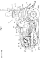
Fig. 3 is a left side view showing an inner arrangement of a hood front portion, -
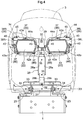
Fig. 4 is a front view showing the inner arrangement of the hood front portion, -
Fig. 5 is a rear view showing the inner arrangement of the hood front portion, -
Fig. 6 is a perspective view showing a side grill, -
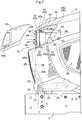
Fig. 7 is a left side view showing the hood front portion, -
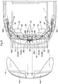
Fig. 8 is a plane view showing the inner arrangement of the hood front portion, and -
Fig. 9 is a left side view showing an optical axis adjusting mechanism. - An embodiment of the present invention will be explained with reference to the accompanying drawings. In the following discussion, it is understood that a direction of arrow F in
Figs. 1 and2 will represent "vehicle body front side", a direction of arrow B will represent "vehicle body rear side", a direction of arrow L show inFig. 2 will represent "vehicle body left side" and a direction of arrow R will represent "vehicle body right side", respectively. -
Figs. 1 and2 show a tractor. This tractor includes avehicle body frame 1 and a wheeltype traveling device 2 supporting thevehicle body frame 1. The travelingdevice 2 includes a left and right pair of steerable and drivablefront wheels 2F and a left and right pair of drivablerear wheels 2B. A left and right pair of fenders FD are provided for covering therear wheels 2B. Each fender FD includes a handrail H acting as a handle to be gripped by a driver when getting on/off the vehicle. - At a front portion of the
vehicle body frame 1, ahood 3 is provided. Inside thehood 3, an engine E is accommodated. Thehood 3 is vertically pivotable about a front pivot X1 extending along a left/right direction between a covering position for covering the engine E and an opening position for exposing the engine E to the outside. At front end portions of thehood 3, there are provided a pair of left andright headlights 22. - At a rear half portion of the
vehicle body frame 1, adriving section 4 is provided. This tractor includes also a hydrostatic steplessspeed changer device 5 as a main speed changer device and a transmission case 6. The transmission case 6 accommodates e.g. a gear type speed changer device (not shown) as an auxiliary speed changer device. - To this tractor, a front loader (not shown) can be attached. Under the
vehicle body frame 1 and between thefront wheels 2F and therear wheels 2B, amower 7 is attached to be lifted up/down. At a rear end portion of thevehicle body frame 1, there is provided alink mechanism 8 that allows attachment of an implement (not shown) such as a rotary tiller, etc. - With this tractor, it is possible to take off a driving power of the engine E via a mid PTO shaft, in order to drive the
mower 7. For driving the implement, with this tractor, a driving power from the engine E can be taken off via a rear PTO shaft. This tractor includes a PTO clutch (not shown) switchable between a transmitting state for transmitting the driving power of the engine E to the rear/mid PTO shaft and a non-transmitting state for not transmitting the driving power of the engine E to the rear/mid PTO shaft. - As shown in
Fig. 1 andFig. 2 , thedriving section 4 includes a driver'sseat 9 where a driver is to be seated, afront panel 10, aright lever guide 11R, aleft lever guide 11L, etc. Thefront panel 10 includes asteering wheel 12 for steering the vehicle body and anaccelerator lever 13 for varying a rotational speed of the engine E. On a left rear side of the driver'sseat 9, there is provided analarm reflecting board 14 for alarming to the rear side of the vehicle. - The driver's
seat 9 includes aleft armrest 15L on which a driver's left arm is to rest and aright armrest 15R on which a driver's right arm is to rest. Theleft armrest 15L and theright armrest 15R respectively is vertically pivotable about a rear pivot along the left/right direction, between a used position where the armrest extends along the vehicle body front/rear direction and a stored position where the armrest extends along the vertical direction. - The
left lever guide 11L is provided on an upper face of the left fender FD. Theleft lever guide 11L is provided with a PTOclutch lever 20 for switching the PTO clutch, aPTO selecting lever 21 for selecting a PTO shaft to be driven. - The
right lever guide 11R is provided on an upper face of the right fender FD. Theright lever guide 11R is provided with an auxiliaryspeed changer lever 16 for speed-changing the auxiliary speed changer device, a switchinglever 17 for switching the travelingdevice 2 between a four-wheel drive state and a two-wheel drive state, alift lever 18 for lifting up/down the implement, and anoperational lever 19 for operating the front loader. - As shown in
Figs. 3 through 5 , thehood 3 is supported to a pair of left and right hood stays 23 to be vertically pivotable about the front pivot X1. In this tractor, there is provided adumper 24 configured to urge thehood 3 for its upward pivoting about the front pivot X1 toward its opened position. To a front face portion of thehood 3, there is attached afront grill 25 defining many air ventilation holes. On the left and the right sides thehood 3, there are respectively attached side grills 26 having many air ventilation holes. - As shown in
Fig. 3 andFig. 6 , theside grill 26 includes a plurality (for instance three, in this embodiment) of protrudingportions 26a and a plurality (for instance seven, in this embodiment) ofpawl portions 26b. Thehood 3 definesinsertion holes 3a in which the protrudingportions 26a are to be inserted, and fit-inholes 3b in which thepawl portions 26b are to be fitted. By inserting the protrudingportions 26a into theinsertion holes 3a and fitting thepawl portions 26b in the fit-inholes 3b, theside grill 26 is attached to thehood 3. - At inner portions of the
hood 3 which portions correspond to theinsertion holes 3a, there are provided push nuts 27. When the protrudingportions 26a are fixed to thepush nuts 27, detachment of theside grill 26 can be prevented. In order to secure attaching strength of theside grill 26 to thehood 3, thepawl portions 26b are disposed at corner portions of the outer circumference of theside grill 26 and also the protrudingportions 26a are disposed at side center portions of the outer circumference of theside grill 26. - As shown in
Figs. 3 through 5 , at a front end portion inside thehood 3, acenter plate 28 for supporting thehood 3 is provided between an upper end portion and a lower end portion of thehood 3. The upper end portion of thecenter plate 28 is fixed by to an upper connectingstay 29 with abolt 30. The upper connectingstay 29 is provided at the upper end portion of thehood 3. The lower end portion of thecenter plate 28 is fixed to a lower connectingframe 31 with abolt 32. - The lower connecting
frame 31 is provided between a left side portion and a right side portion of thehood 3, at the lower end portion of thehood 3. The lower connectingframe 31 includes a pair of left and right connectingportions 33 to be connected to the hood stays 23. The connectingportions 33 are fixed withbolts 34 to the hood stays 23 so as to allow thehood 3 to be vertically pivotable about the front pivot X1. Namely, the hood stays 23 support thehood 3 with allowing its vertical pivoting about the front pivot X1 via thebolts 34. - To the
center plate 28, thefront grill 25 is fixed withbolts 35. Thecenter plate 28, for improvement of the strength of thiscenter plate 28, includes a pair of left and rightbent portions 28a and a pair of left and right reinforcingplates 28b. Thebent portions 28a are bent forwardly from the left and right opposed end portions at a vertical intermediate portion of thecenter plate 28. Thebent portions 28a are formed integral with thecenter plate 28. - The reinforcing
plates 28b are provided on a rear face of the lower portion of thecenter plate 28 to extend perpendicularly relative to this rear face. Each reinforcingplate 28b is a member separate from thecenter plate 28 and fixed (e.g. fixed by welding) to thiscenter plate 28. - As shown in
Fig. 4 ,Fig. 5 , etc., this tractor includes an attachingframe 36 to which theheadlights 22 are to be attached. Theheadlights 22 are fixed to the attachingframe 36 with screws 37 (corresponding to "fixing tool" of the present invention). The attachingframe 36 includes a left attachingframe 36L to which theleft headlight 22 is to be attached and aright attaching frame 36R to which theright headlight 22 is to be attached. The attachingframe 36 can be separated into theleft attaching frame 36L and theright attaching frame 36R. The right end portion of the left attachingframe 36L and the left end portion of theright attaching frame 36R are overlapped with each other in the front/rear direction and fixed (fixed by being fastened to each other) under this state to thecenter plate 28 with thebolts 38. - The left attaching
frame 36L has a shape formed along the outer circumference portion of theleft headlight 22 as viewed in the front/rear direction. Theleft headlight 22 is detachably attached from the front side thereof to theleft attaching frame 36L. The left end portions (upper and lower two portions) of the left attachingframe 36L are fixed to theleft connecting stay 39L withbolts 40. Theleft connecting stay 39L is provided on the left side portion of thehood 3. - The
right attaching frame 36R has a shape formed along the outer circumference portion of theright headlight 22 as viewed in the front/rear direction. Theright headlight 22 is detachably attached from the front side thereof to theright attaching frame 36R. The right end portions (upper and lower two portions) of theright attaching frame 36R are fixed to theright connecting stay 39R with thebolts 40. Theright connecting stay 39R is provided on the right side portion of thehood 3. - As shown in
Figs. 3 through 5 , eachheadlight 22 includes amain body portion 42 accommodating a light source (not shown) and alight transmitting portion 43 provided to a front face portion of themain body portion 42. At an upper portion and a lower portion of themain body portion 42 respectively, there are providedflange portions 42a (corresponding to "fixed portion" relating to the present invention) to be fixed to the attachingframe 36 with thescrews 37. At the upper portion of themain body portion 42, theflange portion 42a is provided at the left/right center portion. At the lower portion of themain body portion 42, theflange portions 42a are provided at a plurality of left/right portions, more particularly, at the respective left and right opposed end portions. - As shown in
Fig. 7 , etc., there is provided aheadlight cover 44 for covering theheadlight 22. Thisheadlight cover 44 is detachably attached to acorresponding opening portion 3c of thehood 3. Theheadlight cover 44 defines a pair of left and right openingportions 44a through which theheadlights 22 are exposed to the outside of thehood 3. Theheadlight cover 44 is fixed to theleft attaching frame 36L and theright attaching frame 36R respectively withbolts 45 and fixed to thecenter plate 28 withbolts 45. - As shown in
Figs. 3 through 5 , there is provided an opticalaxis adjusting mechanism 46 for adjusting an optical axis of theheadlight 22. The opticalaxis adjusting mechanism 46 adjusts the optical axis of the headlight 22 (in the vertical direction and in the vehicle body left/right direction) by varying attaching angles of theheadlight 22 relative to the attachingframe 36 in the vertical direction and the vehicle body left/right direction. The opticalaxis adjusting mechanism 46 includesscrews 37 and springs 47 (corresponding to an "urging member" relating to the present invention). - The
screw 37 is a screw type fixing tool that extends in the vehicle body front/rear direction along theheadlight 22 and the attachingframe 36 and that fixes theheadlight 22 to the attachingframe 36. The attachingframe 36 defines a hole (not shown) in which thescrew 37 is inserted. Theflange portion 42a defines a hole (not shown) in which thescrew 37 is inserted. Thescrew 37 is inserted to the attachingframe 36 from the rear side thereof. In a front face of the portion of theflange portion 42a corresponding to the hole, a welding nut or the like can be provided. - The
screw 37 is fitted on a portion of thescrew 37 which portion is located between the headlight 22 (flange portion 42a) and the attachingframe 36. Thespring 47 is a compression spring which is configured to urge theheadlight 22 to the forward side relative to the attachingframe 36. According to a spacing formed between the headlight 22 (flange portion 42a) and the attachingframe 36, thespring 47 will be expanded/contracted. - As shown in
Fig. 7 andFig. 8 , the opticalaxis adjusting mechanism 46 is operable through the openingportion 3c from the outside of thehood 3 when theheadlight cover 44 is detached from thisopening portion 3c. With this, the opticalaxis adjusting mechanism 46 becomes readily accessible from the outside of thehood 3, so that the optical axis of theheadlight 22 can be adjusted easily. - And, in accordance of fastening degrees of the screw 37 (upper screw 37) corresponding to the
upper flange portion 42a and the screws 37 (lower screws 37) corresponding to thelower flange portions 42a, the attaching angle in vertical direction of theheadlight 22 relative to the attachingframe 36 will vary. With this, the optical axis of theheadlight 22 can be adjusted easily in the vertical direction. - For instance, as shown in
Fig.9 , between theupper flange portion 42a and the attachingframe 36, a spacing SU (upper spacing) is provided. Further, between thelower flange portions 42a and the attachingframe 36, a spacing SL (lower spacing) is provided. Then, if the fastening degrees of theupper screw 37 and thelower screws 37 are adjusted so as to make the upper spacing SU greater than the lower spacing SL, theheadlight 22 will assume a forwardly inclined attaching posture, so that the optical axis of theheadlight 22 is inclined forwardly downwards. - Further, if the fastening degrees of the
upper screw 37 and thelower screws 37 are adjusted so as to make the upper spacing SU smaller than the lower spacing SL, theheadlight 22 will assume a rearwardly inclined attaching posture, so that the optical axis of theheadlight 22 is inclined forwardly upwards. - Still further, if the fastening degrees of the
upper screw 37 and thelower screws 37 are adjusted so as to make the upper spacing SU equal to the lower spacing SL, the optical axis of theheadlight 22 is aligned with the horizontal direction. - Incidentally, through not described in details, similarly to the adjustment method of the optical axis of the
headlight 22 in the vertical direction, according to the fastening degrees of the left andright screws 37 corresponding to thelower flange portions 42a, the attaching angle of theheadlight 22 relative to the attachingframe 36 will vary in the vehicle body left/right direction. With this, the optical axis of theheadlight 22 an be easily adjusted in the vehicle body left/right direction. - Next, other embodiments will be explained. These respective other embodiments, unless contradiction occurs, can be applied in a plurality of combinations to the foregoing embodiment.
- (1) In the foregoing embodiment, two
headlights 22 are provided. Instead, only oneheadlight 22 or three or more headlights can be provided. - (2) In the foregoing embodiment, one
flange portion 42a is provided at the upper portion of theheadlight 22 and twoflange portions 42a are provided at the lower portion of theheadlight 22. However, instead of the above, twoflange portions 42a can be provided at the upper portion of theheadlight 22 and oneflange portion 42a can be provided at the lower portion of theheadlight 22. - (3) In the foregoing embodiment, the
screws 37 are inserted to the attachingframe 36 from the rear side. However, instead of the above, thescrews 37 can be inserted to the attachingframe 36 from the front side. - (4) In the foregoing embodiment, there was shown a tractor having a mower. Instead, the invention can be applied to a tractor not having a mower.
Claims (6)
- A tractor comprising:a vehicle body;a hood (3) provided at a front portion of the vehicle body;a headlight (22) provided at a front portion of the hood (3);an optical axis adjusting mechanism (46) for adjusting an optical axis of the headlight (22); anda headlight cover (44) detachably attached to a corresponding opening portion (3c) of the hood (3) and configured to cover the headlight (22);wherein the optical axis adjusting mechanism (46) is operable through the opening portion (3c) from the outside of the hood (3) when the headlight cover (44) is detached from the opening portion (3c).
- The tractor according to claim 1, wherein:the tractor further comprises:an attaching frame (36) to which the headlight (22) is attached; andwherein the optical axis adjusting mechanism (46) is configured to adjust the optical axis of the headlight (22) by varying attaching angles of the headlight (22) relative to the attaching frame (36) in a vertical direction and a vehicle body left/right direction.
- The tractor according to claim 2, wherein:the headlight (22) is detachably attachable to the attaching frame (36) from the front side thereof; andthe optical axis adjusting mechanism (46) includes a screw type fixing tool (37) extending in a vehicle body front/rear direction between the headlight (22) and the attaching frame (36) and configured to fix the headlight (22) to the attaching frame (36) and an urging member (47) fitted on a portion of the fixing tool (37) between the headlight (22) and the attaching frame (36).
- The tractor according to claim 3, wherein at an upper portion and a lower portion of the headlight (22), there are respectively provided fixed portions (42a) to be fixed to the attaching frame (36) by the fixing tool (37).
- The tractor according to claim 4, wherein at least at one of the upper and lower portions of the headlight (22), the fixed portions (42a) are provided on both left and right sides.
- The tractor according to any one of claims 2-5, wherein the headlight cover (44) is attached to the attaching frame (36).
Applications Claiming Priority (1)
| Application Number | Priority Date | Filing Date | Title |
|---|---|---|---|
| JP2016170017A JP6816998B2 (en) | 2016-08-31 | 2016-08-31 | Tractor |
Publications (2)
| Publication Number | Publication Date |
|---|---|
| EP3290269A1 true EP3290269A1 (en) | 2018-03-07 |
| EP3290269B1 EP3290269B1 (en) | 2021-06-30 |
Family
ID=58765737
Family Applications (1)
| Application Number | Title | Priority Date | Filing Date |
|---|---|---|---|
| EP17172239.0A Active EP3290269B1 (en) | 2016-08-31 | 2017-05-22 | Tractor |
Country Status (2)
| Country | Link |
|---|---|
| EP (1) | EP3290269B1 (en) |
| JP (1) | JP6816998B2 (en) |
Cited By (1)
| Publication number | Priority date | Publication date | Assignee | Title |
|---|---|---|---|---|
| US11628761B1 (en) | 2022-06-30 | 2023-04-18 | Kawasaki Motors, Ltd. | Headlight aiming mechanism and off-road vehicle including the same |
Families Citing this family (2)
| Publication number | Priority date | Publication date | Assignee | Title |
|---|---|---|---|---|
| JP7849138B2 (en) * | 2020-10-20 | 2026-04-21 | ヤンマーパワーテクノロジー株式会社 | tractor |
| JP7650257B2 (en) * | 2022-10-21 | 2025-03-24 | 株式会社竹内製作所 | Work vehicles |
Citations (4)
| Publication number | Priority date | Publication date | Assignee | Title |
|---|---|---|---|---|
| JP2004106787A (en) * | 2002-09-20 | 2004-04-08 | Mitsubishi Agricult Mach Co Ltd | Working light mounting structure in mobile agricultural machine |
| JP2004224274A (en) | 2003-01-24 | 2004-08-12 | Kubota Corp | Bonnet structure of running vehicle |
| JP2004314827A (en) * | 2003-04-17 | 2004-11-11 | Mitsubishi Agricult Mach Co Ltd | Front grille structure of farming machine |
| US20110051453A1 (en) * | 2009-08-25 | 2011-03-03 | Satoshi Nagasawa | Vehicle light |
Family Cites Families (5)
| Publication number | Priority date | Publication date | Assignee | Title |
|---|---|---|---|---|
| JPS51115289U (en) * | 1975-03-14 | 1976-09-18 | ||
| JPH0653472B2 (en) * | 1986-05-30 | 1994-07-20 | 本田技研工業株式会社 | Optical axis adjustment device for motorcycles |
| JPH02124382A (en) * | 1988-11-01 | 1990-05-11 | Honda Motor Co Ltd | Tractor bonnet hinge structure |
| JP3800647B2 (en) * | 1995-09-25 | 2006-07-26 | マツダ株式会社 | Automotive headlight equipment |
| JP4691905B2 (en) * | 2004-05-31 | 2011-06-01 | 井関農機株式会社 | Work vehicle |
-
2016
- 2016-08-31 JP JP2016170017A patent/JP6816998B2/en active Active
-
2017
- 2017-05-22 EP EP17172239.0A patent/EP3290269B1/en active Active
Patent Citations (4)
| Publication number | Priority date | Publication date | Assignee | Title |
|---|---|---|---|---|
| JP2004106787A (en) * | 2002-09-20 | 2004-04-08 | Mitsubishi Agricult Mach Co Ltd | Working light mounting structure in mobile agricultural machine |
| JP2004224274A (en) | 2003-01-24 | 2004-08-12 | Kubota Corp | Bonnet structure of running vehicle |
| JP2004314827A (en) * | 2003-04-17 | 2004-11-11 | Mitsubishi Agricult Mach Co Ltd | Front grille structure of farming machine |
| US20110051453A1 (en) * | 2009-08-25 | 2011-03-03 | Satoshi Nagasawa | Vehicle light |
Cited By (1)
| Publication number | Priority date | Publication date | Assignee | Title |
|---|---|---|---|---|
| US11628761B1 (en) | 2022-06-30 | 2023-04-18 | Kawasaki Motors, Ltd. | Headlight aiming mechanism and off-road vehicle including the same |
Also Published As
| Publication number | Publication date |
|---|---|
| EP3290269B1 (en) | 2021-06-30 |
| JP2018034677A (en) | 2018-03-08 |
| JP6816998B2 (en) | 2021-01-20 |
Similar Documents
| Publication | Publication Date | Title |
|---|---|---|
| JP6374325B2 (en) | Mower | |
| US9925866B2 (en) | Work vehicle | |
| EP3263371A1 (en) | Axle device | |
| EP3290269B1 (en) | Tractor | |
| EP1873009B1 (en) | Tractor with an assist grip | |
| EP1661795B1 (en) | Tractor with a splitted body surrounding the engine compartiment | |
| US4450927A (en) | Apparatus for controlling agricultural tractor | |
| EP3289851B1 (en) | Work vehicle | |
| US11414035B2 (en) | Work vehicle | |
| JP6341875B2 (en) | Work vehicle | |
| JP6976121B2 (en) | Work platform | |
| JP2017044636A (en) | Mounting structure of radar | |
| US11753797B2 (en) | Working vehicle | |
| JP2003341526A (en) | Steering handle mounting structure | |
| JP2005029125A (en) | Tractor | |
| JP2005059734A (en) | Tractor | |
| JP2005029124A (en) | Tractor | |
| JP7103317B2 (en) | Work vehicle | |
| JP2005029126A (en) | Tractor | |
| JP2005029127A (en) | Tractor | |
| JP4570510B2 (en) | Tractor | |
| US20220339979A1 (en) | Tractor | |
| JP2000085615A (en) | Structure of safety frame support portion for tractor | |
| EP2487078A1 (en) | Working Vehicle | |
| JP2005343350A (en) | Tractor |
Legal Events
| Date | Code | Title | Description |
|---|---|---|---|
| PUAI | Public reference made under article 153(3) epc to a published international application that has entered the european phase |
Free format text: ORIGINAL CODE: 0009012 |
|
| STAA | Information on the status of an ep patent application or granted ep patent |
Free format text: STATUS: THE APPLICATION HAS BEEN PUBLISHED |
|
| AK | Designated contracting states |
Kind code of ref document: A1 Designated state(s): AL AT BE BG CH CY CZ DE DK EE ES FI FR GB GR HR HU IE IS IT LI LT LU LV MC MK MT NL NO PL PT RO RS SE SI SK SM TR |
|
| AX | Request for extension of the european patent |
Extension state: BA ME |
|
| STAA | Information on the status of an ep patent application or granted ep patent |
Free format text: STATUS: REQUEST FOR EXAMINATION WAS MADE |
|
| 17P | Request for examination filed |
Effective date: 20180904 |
|
| RBV | Designated contracting states (corrected) |
Designated state(s): AL AT BE BG CH CY CZ DE DK EE ES FI FR GB GR HR HU IE IS IT LI LT LU LV MC MK MT NL NO PL PT RO RS SE SI SK SM TR |
|
| STAA | Information on the status of an ep patent application or granted ep patent |
Free format text: STATUS: EXAMINATION IS IN PROGRESS |
|
| 17Q | First examination report despatched |
Effective date: 20200511 |
|
| REG | Reference to a national code |
Ref country code: DE Ref legal event code: R079 Ref document number: 602017041108 Country of ref document: DE Free format text: PREVIOUS MAIN CLASS: B60Q0001068000 Ipc: B60Q0001000000 |
|
| RIC1 | Information provided on ipc code assigned before grant |
Ipc: B60Q 1/04 20060101ALI20201218BHEP Ipc: B60Q 1/00 20060101AFI20201218BHEP Ipc: B60Q 1/068 20060101ALI20201218BHEP |
|
| GRAP | Despatch of communication of intention to grant a patent |
Free format text: ORIGINAL CODE: EPIDOSNIGR1 |
|
| STAA | Information on the status of an ep patent application or granted ep patent |
Free format text: STATUS: GRANT OF PATENT IS INTENDED |
|
| INTG | Intention to grant announced |
Effective date: 20210208 |
|
| GRAS | Grant fee paid |
Free format text: ORIGINAL CODE: EPIDOSNIGR3 |
|
| GRAA | (expected) grant |
Free format text: ORIGINAL CODE: 0009210 |
|
| STAA | Information on the status of an ep patent application or granted ep patent |
Free format text: STATUS: THE PATENT HAS BEEN GRANTED |
|
| AK | Designated contracting states |
Kind code of ref document: B1 Designated state(s): AL AT BE BG CH CY CZ DE DK EE ES FI FR GB GR HR HU IE IS IT LI LT LU LV MC MK MT NL NO PL PT RO RS SE SI SK SM TR |
|
| REG | Reference to a national code |
Ref country code: CH Ref legal event code: EP |
|
| REG | Reference to a national code |
Ref country code: DE Ref legal event code: R096 Ref document number: 602017041108 Country of ref document: DE Ref country code: AT Ref legal event code: REF Ref document number: 1406075 Country of ref document: AT Kind code of ref document: T Effective date: 20210715 |
|
| REG | Reference to a national code |
Ref country code: IE Ref legal event code: FG4D |
|
| REG | Reference to a national code |
Ref country code: LT Ref legal event code: MG9D |
|
| PG25 | Lapsed in a contracting state [announced via postgrant information from national office to epo] |
Ref country code: HR Free format text: LAPSE BECAUSE OF FAILURE TO SUBMIT A TRANSLATION OF THE DESCRIPTION OR TO PAY THE FEE WITHIN THE PRESCRIBED TIME-LIMIT Effective date: 20210630 Ref country code: BG Free format text: LAPSE BECAUSE OF FAILURE TO SUBMIT A TRANSLATION OF THE DESCRIPTION OR TO PAY THE FEE WITHIN THE PRESCRIBED TIME-LIMIT Effective date: 20210930 Ref country code: FI Free format text: LAPSE BECAUSE OF FAILURE TO SUBMIT A TRANSLATION OF THE DESCRIPTION OR TO PAY THE FEE WITHIN THE PRESCRIBED TIME-LIMIT Effective date: 20210630 |
|
| REG | Reference to a national code |
Ref country code: NL Ref legal event code: MP Effective date: 20210630 |
|
| REG | Reference to a national code |
Ref country code: AT Ref legal event code: MK05 Ref document number: 1406075 Country of ref document: AT Kind code of ref document: T Effective date: 20210630 |
|
| PG25 | Lapsed in a contracting state [announced via postgrant information from national office to epo] |
Ref country code: SE Free format text: LAPSE BECAUSE OF FAILURE TO SUBMIT A TRANSLATION OF THE DESCRIPTION OR TO PAY THE FEE WITHIN THE PRESCRIBED TIME-LIMIT Effective date: 20210630 Ref country code: RS Free format text: LAPSE BECAUSE OF FAILURE TO SUBMIT A TRANSLATION OF THE DESCRIPTION OR TO PAY THE FEE WITHIN THE PRESCRIBED TIME-LIMIT Effective date: 20210630 Ref country code: NO Free format text: LAPSE BECAUSE OF FAILURE TO SUBMIT A TRANSLATION OF THE DESCRIPTION OR TO PAY THE FEE WITHIN THE PRESCRIBED TIME-LIMIT Effective date: 20210930 Ref country code: GR Free format text: LAPSE BECAUSE OF FAILURE TO SUBMIT A TRANSLATION OF THE DESCRIPTION OR TO PAY THE FEE WITHIN THE PRESCRIBED TIME-LIMIT Effective date: 20211001 Ref country code: LV Free format text: LAPSE BECAUSE OF FAILURE TO SUBMIT A TRANSLATION OF THE DESCRIPTION OR TO PAY THE FEE WITHIN THE PRESCRIBED TIME-LIMIT Effective date: 20210630 |
|
| PG25 | Lapsed in a contracting state [announced via postgrant information from national office to epo] |
Ref country code: SK Free format text: LAPSE BECAUSE OF FAILURE TO SUBMIT A TRANSLATION OF THE DESCRIPTION OR TO PAY THE FEE WITHIN THE PRESCRIBED TIME-LIMIT Effective date: 20210630 Ref country code: SM Free format text: LAPSE BECAUSE OF FAILURE TO SUBMIT A TRANSLATION OF THE DESCRIPTION OR TO PAY THE FEE WITHIN THE PRESCRIBED TIME-LIMIT Effective date: 20210630 Ref country code: PT Free format text: LAPSE BECAUSE OF FAILURE TO SUBMIT A TRANSLATION OF THE DESCRIPTION OR TO PAY THE FEE WITHIN THE PRESCRIBED TIME-LIMIT Effective date: 20211102 Ref country code: RO Free format text: LAPSE BECAUSE OF FAILURE TO SUBMIT A TRANSLATION OF THE DESCRIPTION OR TO PAY THE FEE WITHIN THE PRESCRIBED TIME-LIMIT Effective date: 20210630 Ref country code: NL Free format text: LAPSE BECAUSE OF FAILURE TO SUBMIT A TRANSLATION OF THE DESCRIPTION OR TO PAY THE FEE WITHIN THE PRESCRIBED TIME-LIMIT Effective date: 20210630 Ref country code: ES Free format text: LAPSE BECAUSE OF FAILURE TO SUBMIT A TRANSLATION OF THE DESCRIPTION OR TO PAY THE FEE WITHIN THE PRESCRIBED TIME-LIMIT Effective date: 20210630 Ref country code: AT Free format text: LAPSE BECAUSE OF FAILURE TO SUBMIT A TRANSLATION OF THE DESCRIPTION OR TO PAY THE FEE WITHIN THE PRESCRIBED TIME-LIMIT Effective date: 20210630 Ref country code: CZ Free format text: LAPSE BECAUSE OF FAILURE TO SUBMIT A TRANSLATION OF THE DESCRIPTION OR TO PAY THE FEE WITHIN THE PRESCRIBED TIME-LIMIT Effective date: 20210630 Ref country code: EE Free format text: LAPSE BECAUSE OF FAILURE TO SUBMIT A TRANSLATION OF THE DESCRIPTION OR TO PAY THE FEE WITHIN THE PRESCRIBED TIME-LIMIT Effective date: 20210630 |
|
| PG25 | Lapsed in a contracting state [announced via postgrant information from national office to epo] |
Ref country code: PL Free format text: LAPSE BECAUSE OF FAILURE TO SUBMIT A TRANSLATION OF THE DESCRIPTION OR TO PAY THE FEE WITHIN THE PRESCRIBED TIME-LIMIT Effective date: 20210630 |
|
| REG | Reference to a national code |
Ref country code: DE Ref legal event code: R097 Ref document number: 602017041108 Country of ref document: DE |
|
| PG25 | Lapsed in a contracting state [announced via postgrant information from national office to epo] |
Ref country code: DK Free format text: LAPSE BECAUSE OF FAILURE TO SUBMIT A TRANSLATION OF THE DESCRIPTION OR TO PAY THE FEE WITHIN THE PRESCRIBED TIME-LIMIT Effective date: 20210630 |
|
| PLBE | No opposition filed within time limit |
Free format text: ORIGINAL CODE: 0009261 |
|
| STAA | Information on the status of an ep patent application or granted ep patent |
Free format text: STATUS: NO OPPOSITION FILED WITHIN TIME LIMIT |
|
| PG25 | Lapsed in a contracting state [announced via postgrant information from national office to epo] |
Ref country code: AL Free format text: LAPSE BECAUSE OF FAILURE TO SUBMIT A TRANSLATION OF THE DESCRIPTION OR TO PAY THE FEE WITHIN THE PRESCRIBED TIME-LIMIT Effective date: 20210630 |
|
| 26N | No opposition filed |
Effective date: 20220331 |
|
| PG25 | Lapsed in a contracting state [announced via postgrant information from national office to epo] |
Ref country code: IT Free format text: LAPSE BECAUSE OF FAILURE TO SUBMIT A TRANSLATION OF THE DESCRIPTION OR TO PAY THE FEE WITHIN THE PRESCRIBED TIME-LIMIT Effective date: 20210630 |
|
| REG | Reference to a national code |
Ref country code: DE Ref legal event code: R119 Ref document number: 602017041108 Country of ref document: DE |
|
| REG | Reference to a national code |
Ref country code: CH Ref legal event code: PL |
|
| REG | Reference to a national code |
Ref country code: BE Ref legal event code: MM Effective date: 20220531 |
|
| GBPC | Gb: european patent ceased through non-payment of renewal fee |
Effective date: 20220522 |
|
| PG25 | Lapsed in a contracting state [announced via postgrant information from national office to epo] |
Ref country code: MC Free format text: LAPSE BECAUSE OF FAILURE TO SUBMIT A TRANSLATION OF THE DESCRIPTION OR TO PAY THE FEE WITHIN THE PRESCRIBED TIME-LIMIT Effective date: 20210630 Ref country code: LU Free format text: LAPSE BECAUSE OF NON-PAYMENT OF DUE FEES Effective date: 20220522 Ref country code: LI Free format text: LAPSE BECAUSE OF NON-PAYMENT OF DUE FEES Effective date: 20220531 Ref country code: CH Free format text: LAPSE BECAUSE OF NON-PAYMENT OF DUE FEES Effective date: 20220531 |
|
| REG | Reference to a national code |
Ref country code: FR Ref legal event code: PLFP Year of fee payment: 7 |
|
| PG25 | Lapsed in a contracting state [announced via postgrant information from national office to epo] |
Ref country code: LT Free format text: LAPSE BECAUSE OF FAILURE TO SUBMIT A TRANSLATION OF THE DESCRIPTION OR TO PAY THE FEE WITHIN THE PRESCRIBED TIME-LIMIT Effective date: 20210630 Ref country code: IE Free format text: LAPSE BECAUSE OF NON-PAYMENT OF DUE FEES Effective date: 20220522 |
|
| PG25 | Lapsed in a contracting state [announced via postgrant information from national office to epo] |
Ref country code: GB Free format text: LAPSE BECAUSE OF NON-PAYMENT OF DUE FEES Effective date: 20220522 Ref country code: DE Free format text: LAPSE BECAUSE OF NON-PAYMENT OF DUE FEES Effective date: 20221201 Ref country code: BE Free format text: LAPSE BECAUSE OF NON-PAYMENT OF DUE FEES Effective date: 20220531 |
|
| PG25 | Lapsed in a contracting state [announced via postgrant information from national office to epo] |
Ref country code: HU Free format text: LAPSE BECAUSE OF FAILURE TO SUBMIT A TRANSLATION OF THE DESCRIPTION OR TO PAY THE FEE WITHIN THE PRESCRIBED TIME-LIMIT; INVALID AB INITIO Effective date: 20170522 |
|
| PG25 | Lapsed in a contracting state [announced via postgrant information from national office to epo] |
Ref country code: MK Free format text: LAPSE BECAUSE OF FAILURE TO SUBMIT A TRANSLATION OF THE DESCRIPTION OR TO PAY THE FEE WITHIN THE PRESCRIBED TIME-LIMIT Effective date: 20210630 Ref country code: CY Free format text: LAPSE BECAUSE OF FAILURE TO SUBMIT A TRANSLATION OF THE DESCRIPTION OR TO PAY THE FEE WITHIN THE PRESCRIBED TIME-LIMIT Effective date: 20210630 |
|
| PG25 | Lapsed in a contracting state [announced via postgrant information from national office to epo] |
Ref country code: TR Free format text: LAPSE BECAUSE OF FAILURE TO SUBMIT A TRANSLATION OF THE DESCRIPTION OR TO PAY THE FEE WITHIN THE PRESCRIBED TIME-LIMIT Effective date: 20210630 |
|
| PG25 | Lapsed in a contracting state [announced via postgrant information from national office to epo] |
Ref country code: MT Free format text: LAPSE BECAUSE OF FAILURE TO SUBMIT A TRANSLATION OF THE DESCRIPTION OR TO PAY THE FEE WITHIN THE PRESCRIBED TIME-LIMIT Effective date: 20210630 |
|
| PGFP | Annual fee paid to national office [announced via postgrant information from national office to epo] |
Ref country code: FR Payment date: 20250401 Year of fee payment: 9 |