EP3290243A1 - Suspension device - Google Patents
Suspension device Download PDFInfo
- Publication number
- EP3290243A1 EP3290243A1 EP17189141.9A EP17189141A EP3290243A1 EP 3290243 A1 EP3290243 A1 EP 3290243A1 EP 17189141 A EP17189141 A EP 17189141A EP 3290243 A1 EP3290243 A1 EP 3290243A1
- Authority
- EP
- European Patent Office
- Prior art keywords
- resistance value
- speed
- motor
- movable shaft
- suspension device
- Prior art date
- Legal status (The legal status is an assumption and is not a legal conclusion. Google has not performed a legal analysis and makes no representation as to the accuracy of the status listed.)
- Withdrawn
Links
- 239000000725 suspension Substances 0.000 title claims abstract description 83
- 238000013016 damping Methods 0.000 claims abstract description 67
- 238000006243 chemical reaction Methods 0.000 claims description 42
- 230000001172 regenerating effect Effects 0.000 claims description 21
- 230000007274 generation of a signal involved in cell-cell signaling Effects 0.000 claims description 13
- 230000008859 change Effects 0.000 claims description 4
- 239000006096 absorbing agent Substances 0.000 description 33
- 238000010586 diagram Methods 0.000 description 12
- 230000035939 shock Effects 0.000 description 8
- 229920006395 saturated elastomer Polymers 0.000 description 7
- 239000003990 capacitor Substances 0.000 description 3
- 230000007246 mechanism Effects 0.000 description 3
- 238000000418 atomic force spectrum Methods 0.000 description 2
- 238000005259 measurement Methods 0.000 description 2
- 230000008929 regeneration Effects 0.000 description 2
- 238000011069 regeneration method Methods 0.000 description 2
- 239000008186 active pharmaceutical agent Substances 0.000 description 1
- 238000005352 clarification Methods 0.000 description 1
- 230000002093 peripheral effect Effects 0.000 description 1
- 230000009467 reduction Effects 0.000 description 1
- 230000004044 response Effects 0.000 description 1
- 239000011800 void material Substances 0.000 description 1
- 238000003466 welding Methods 0.000 description 1
Images


Classifications
-
- B—PERFORMING OPERATIONS; TRANSPORTING
- B60—VEHICLES IN GENERAL
- B60G—VEHICLE SUSPENSION ARRANGEMENTS
- B60G17/00—Resilient suspensions having means for adjusting the spring or vibration-damper characteristics, for regulating the distance between a supporting surface and a sprung part of vehicle or for locking suspension during use to meet varying vehicular or surface conditions, e.g. due to speed or load
-
- B—PERFORMING OPERATIONS; TRANSPORTING
- B60—VEHICLES IN GENERAL
- B60G—VEHICLE SUSPENSION ARRANGEMENTS
- B60G13/00—Resilient suspensions characterised by arrangement, location or type of vibration dampers
- B60G13/14—Resilient suspensions characterised by arrangement, location or type of vibration dampers having dampers accumulating utilisable energy, e.g. compressing air
-
- B—PERFORMING OPERATIONS; TRANSPORTING
- B60—VEHICLES IN GENERAL
- B60G—VEHICLE SUSPENSION ARRANGEMENTS
- B60G13/00—Resilient suspensions characterised by arrangement, location or type of vibration dampers
- B60G13/16—Resilient suspensions characterised by arrangement, location or type of vibration dampers having dynamic absorbers as main damping means, i.e. spring-mass system vibrating out of phase
- B60G13/18—Resilient suspensions characterised by arrangement, location or type of vibration dampers having dynamic absorbers as main damping means, i.e. spring-mass system vibrating out of phase combined with energy-absorbing means
-
- B—PERFORMING OPERATIONS; TRANSPORTING
- B60—VEHICLES IN GENERAL
- B60G—VEHICLE SUSPENSION ARRANGEMENTS
- B60G17/00—Resilient suspensions having means for adjusting the spring or vibration-damper characteristics, for regulating the distance between a supporting surface and a sprung part of vehicle or for locking suspension during use to meet varying vehicular or surface conditions, e.g. due to speed or load
- B60G17/015—Resilient suspensions having means for adjusting the spring or vibration-damper characteristics, for regulating the distance between a supporting surface and a sprung part of vehicle or for locking suspension during use to meet varying vehicular or surface conditions, e.g. due to speed or load the regulating means comprising electric or electronic elements
- B60G17/0152—Resilient suspensions having means for adjusting the spring or vibration-damper characteristics, for regulating the distance between a supporting surface and a sprung part of vehicle or for locking suspension during use to meet varying vehicular or surface conditions, e.g. due to speed or load the regulating means comprising electric or electronic elements characterised by the action on a particular type of suspension unit
- B60G17/0157—Resilient suspensions having means for adjusting the spring or vibration-damper characteristics, for regulating the distance between a supporting surface and a sprung part of vehicle or for locking suspension during use to meet varying vehicular or surface conditions, e.g. due to speed or load the regulating means comprising electric or electronic elements characterised by the action on a particular type of suspension unit non-fluid unit, e.g. electric motor
-
- B—PERFORMING OPERATIONS; TRANSPORTING
- B60—VEHICLES IN GENERAL
- B60G—VEHICLE SUSPENSION ARRANGEMENTS
- B60G17/00—Resilient suspensions having means for adjusting the spring or vibration-damper characteristics, for regulating the distance between a supporting surface and a sprung part of vehicle or for locking suspension during use to meet varying vehicular or surface conditions, e.g. due to speed or load
- B60G17/015—Resilient suspensions having means for adjusting the spring or vibration-damper characteristics, for regulating the distance between a supporting surface and a sprung part of vehicle or for locking suspension during use to meet varying vehicular or surface conditions, e.g. due to speed or load the regulating means comprising electric or electronic elements
- B60G17/016—Resilient suspensions having means for adjusting the spring or vibration-damper characteristics, for regulating the distance between a supporting surface and a sprung part of vehicle or for locking suspension during use to meet varying vehicular or surface conditions, e.g. due to speed or load the regulating means comprising electric or electronic elements characterised by their responsiveness, when the vehicle is travelling, to specific motion, a specific condition, or driver input
-
- B—PERFORMING OPERATIONS; TRANSPORTING
- B60—VEHICLES IN GENERAL
- B60G—VEHICLE SUSPENSION ARRANGEMENTS
- B60G17/00—Resilient suspensions having means for adjusting the spring or vibration-damper characteristics, for regulating the distance between a supporting surface and a sprung part of vehicle or for locking suspension during use to meet varying vehicular or surface conditions, e.g. due to speed or load
- B60G17/015—Resilient suspensions having means for adjusting the spring or vibration-damper characteristics, for regulating the distance between a supporting surface and a sprung part of vehicle or for locking suspension during use to meet varying vehicular or surface conditions, e.g. due to speed or load the regulating means comprising electric or electronic elements
- B60G17/018—Resilient suspensions having means for adjusting the spring or vibration-damper characteristics, for regulating the distance between a supporting surface and a sprung part of vehicle or for locking suspension during use to meet varying vehicular or surface conditions, e.g. due to speed or load the regulating means comprising electric or electronic elements characterised by the use of a specific signal treatment or control method
-
- B—PERFORMING OPERATIONS; TRANSPORTING
- B60—VEHICLES IN GENERAL
- B60G—VEHICLE SUSPENSION ARRANGEMENTS
- B60G17/00—Resilient suspensions having means for adjusting the spring or vibration-damper characteristics, for regulating the distance between a supporting surface and a sprung part of vehicle or for locking suspension during use to meet varying vehicular or surface conditions, e.g. due to speed or load
- B60G17/06—Characteristics of dampers, e.g. mechanical dampers
-
- F—MECHANICAL ENGINEERING; LIGHTING; HEATING; WEAPONS; BLASTING
- F16—ENGINEERING ELEMENTS AND UNITS; GENERAL MEASURES FOR PRODUCING AND MAINTAINING EFFECTIVE FUNCTIONING OF MACHINES OR INSTALLATIONS; THERMAL INSULATION IN GENERAL
- F16F—SPRINGS; SHOCK-ABSORBERS; MEANS FOR DAMPING VIBRATION
- F16F15/00—Suppression of vibrations in systems; Means or arrangements for avoiding or reducing out-of-balance forces, e.g. due to motion
- F16F15/02—Suppression of vibrations of non-rotating, e.g. reciprocating systems; Suppression of vibrations of rotating systems by use of members not moving with the rotating systems
- F16F15/03—Suppression of vibrations of non-rotating, e.g. reciprocating systems; Suppression of vibrations of rotating systems by use of members not moving with the rotating systems using magnetic or electromagnetic means
-
- B—PERFORMING OPERATIONS; TRANSPORTING
- B60—VEHICLES IN GENERAL
- B60G—VEHICLE SUSPENSION ARRANGEMENTS
- B60G2202/00—Indexing codes relating to the type of spring, damper or actuator
- B60G2202/40—Type of actuator
- B60G2202/42—Electric actuator
-
- B—PERFORMING OPERATIONS; TRANSPORTING
- B60—VEHICLES IN GENERAL
- B60G—VEHICLE SUSPENSION ARRANGEMENTS
- B60G2300/00—Indexing codes relating to the type of vehicle
- B60G2300/60—Vehicles using regenerative power
-
- B—PERFORMING OPERATIONS; TRANSPORTING
- B60—VEHICLES IN GENERAL
- B60G—VEHICLE SUSPENSION ARRANGEMENTS
- B60G2500/00—Indexing codes relating to the regulated action or device
- B60G2500/10—Damping action or damper
-
- B—PERFORMING OPERATIONS; TRANSPORTING
- B60—VEHICLES IN GENERAL
- B60G—VEHICLE SUSPENSION ARRANGEMENTS
- B60G2600/00—Indexing codes relating to particular elements, systems or processes used on suspension systems or suspension control systems
- B60G2600/18—Automatic control means
- B60G2600/181—Signal modulation; pulse-width, frequency-phase
Definitions
- the invention relates to a suspension device.
- the invention relates to a suspension device including an electromagnetic absorber that is provided in juxtaposition with a spring of a suspension and converts kinetic energy, which is generated by approaching-separating motion between a spring upper portion and a spring lower portion, to electrical energy, for example.
- an electromagnetic suspension device including an electromagnetic absorber that uses an electromagnetic motor to generate regenerative power and dampens a force in a direction in which a spring upper portion and a spring lower portion approach or separate from each other by a regenerative operation has been examined.
- One example of the suspension device including such an electromagnetic absorber is disclosed in Japanese Patent Application Publication No. 2010-228579 ( JP 2010-228579 A ).
- a suspension system described in JP 2010-228579 A includes: plural electromagnetic shock absorbers that are respectively provided for plural wheels, and each of which has an electromagnetic motor and, depending on a force generated by the electromagnetic motor, generates a force in a direction in which a spring upper portion and a spring lower portion approach or separate from each other; plural contact-type relays that are respectively provided for the plural shock absorbers, and each of which switches between a connected state and a cutoff state, the connected state being a state where a power supply and the electromagnetic motor provided in one corresponding to a magnetic core of the plural shock absorbers are connected and a current flow therebetween is allowed, and the cutoff state being a state where the power supply and the electromagnetic motor are disconnected and the current flow between the electromagnetic motor and the power supply is thereby prevented; and a relay controller that controls each of the relays to selectively realize the connected state and the cutoff state of each of the shock absorbers, the relay controller being configured to normally realize the connected states of all of the shock absorbers and to realize the cutoff state of one of the shock absorb
- a damping force may be saturated in a speed range where a stroke speed of a movable shaft causing an operation of the movable shaft of the absorber becomes equal to or higher than a specified speed.
- the invention provides a suspension device capable of increasing a damping force in a speed range where the damping force is saturated due to a characteristic of a motor.
- a suspension device includes: a spring provided between an upper member and a lower member; a motor provided in juxtaposition with the spring, the motor being configured to generate power in accordance with a speed at which a movable shaft is operated, the movable shaft being movable in accordance with operations of the upper member and the lower member in an expansion-contraction direction of the spring; a power consumption circuit including a variable load circuit, the variable load circuit being configured to generate a damping force in the motor by consuming the power generated in the motor and to change the damping force; and a load control section configured to control the variable load circuit such that consumed power by the variable load circuit is increased along with an increase in a speed of the movable shaft.
- a resistance value of variable resistor in the power consumption circuit is increased along with an increase in an operation speed of the motor.
- the consumed power in the power consumption circuit is increased.
- a reduction in the damping force can be suppressed in a speed range where the damping force is saturated due to a characteristic of the motor.
- the load control section may be configured to maintain a resistance value of the variable load circuit to a specified value when the speed of the movable shaft is equal to or lower than a specified speed.
- the resistance value of the variable resistor is set to a fixed resistance value, with which a difference between the damping force and a reference damping force serving as a reference of the damping force falls within a certain range. Note that, when the speed of the movable shaft of the motor is equal to or higher than the specified speed, the damping force that is saturated with the fixed resistance value is compensated by changing the resistance value of the variable resistor. In this way, a characteristic of the suspension device can be brought close to an ideal state.
- the load control section may have a conversion table that indicates a relationship between the speed of the movable shaft and a resistance value of the variable load circuit, and the load control section is configured to output a load resistance value setting signal based on the conversion table, the load resistance value setting signal being used to set a resistance value of the variable load circuit to a value corresponding to the speed of the movable shaft.
- a value of the load resistance value setting signal can be determined at a high speed.
- variable load circuit may have: a load resistor that has a predetermined resistance value; and a switch connected in series with the load resistor, and the load control section may have a control signal generation section that is configured to generate a pulse width modulation signal such that a duty ratio is reduced as a resistance value of the variable load circuit is increased, the pulse width modulation signal being used to switch an opened- closed state of the switch.
- the resistance value on a time axis can be changed.
- a scale of the circuit can be reduced, and a response speed of a change in the resistance value can be increased.
- the load control section may be configured to switch an operation between a first operation mode and a second operation mode in accordance with a mode switching signal provided from outside.
- the load control section may be configured to, in the first operation mode, the load control section may be configured to control a resistance value of the variable load circuit such that the resistance value of the variable load circuit is increased along with an increase in the speed of the movable shaft, and in the second operation mode, control the resistance value of the variable load circuit such that the damping force in the variable load circuit becomes the largest for the speed of the movable shaft.
- the operation mode in which a regenerative amount of the power generated by the motor is maximized can be added.
- the load control section may have: a first conversion table that indicates a relationship between the speed of the movable shaft and the resistance value of the variable load circuit, the first conversion table being provided for the first operation mode; a second conversion table that indicates a relationship between the speed of the movable shaft and the resistance value of the variable load circuit, the second conversion table being provided for the second operation mode; and a control signal generation section that is configured to read a duty ratio setting value used to realize the speed of the movable shaft and the resistance value of the variable load circuit from either one of the first conversion table and the second conversion table in accordance with the mode switching signal and to generate a pulse width modulation signal with the duty ratio that corresponds to the read duty ratio setting value.
- a value of the load resistance value setting signal can be determined at a high speed.
- the load control section may have a control signal generation section configured to generate a load resistance value setting signal including a duty ratio that corresponds to the speed of the movable shaft
- the variable load circuit may include: a buck-boost circuit that is configured to step up or step down a motor voltage generated in the motor based on the load resistance value setting signal to generate an output voltage with a constant voltage value; and a secondary battery, to which the output voltage is applied, and to which regenerative power generated in the motor is stored.
- the power generated by the motor can be regenerated to the secondary battery.
- the duty ratio of the load resistance value setting signal may be set such that the damping force generated by the variable load circuit by consuming the power generated in the motor becomes a target damping force.
- a damping force characteristic of the suspension device can realize the target damping force.
- the suspension device according to the invention can increase the damping force in a speed range where the damping force is saturated due to a characteristic of the motor.
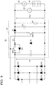
- FIG. 1 is a block diagram that illustrates the configuration of the suspension device 1 according to the first embodiment.
- the suspension device 1 has an upper member (for example, an upper spring member 10), a lower member (for example, a lower spring member 11), a spring 12, a tire 13, a motor 20, a ball screw 21, a screw support member 22, a power consumption circuit 14, and an electronic control circuit 15.
- the motor 20, the ball screw 21, and the screw support member 22 constitute an electromagnetic absorber.
- the upper spring member 10 is connected to a vehicle body, for example.
- the lower spring member 11 is attached to a suspension arm that is attached to the vehicle, for example, and receives a force from the tire 13.
- the tire 13 is shown as a model that is configured by including a spring and a roller.
- the spring 12 is provided in a manner to be held between the upper spring member 10 and the lower spring member 11.
- the motor 20 is provided in juxtaposition with the spring 12 and generates power in accordance with an operation speed of a movable shaft (hereinafter also referred to as a stroke speed) that is operated in accordance with operations of the upper spring member 10 and the lower spring member 11 in an expansion-contraction direction of the spring 12.
- the motor 20 generates a current in accordance with motion of the movable shaft and thereby generates a damping force.
- the ball screw 21 and the screw support member 22 constitute an operation conversion mechanism.
- This operation conversion mechanism is disposed in series with the motor 20 between the upper spring member 10 and the lower spring member 11.
- the operation conversion mechanism converts an approaching-separating operation between the upper spring member 10 and the lower spring member 11 to the motion of the movable shaft of the motor 20.
- the screw support member 22 causes rotation of the ball screw 21 in accordance with said approaching-separating operation, and the movable shaft of the motor 20, which is coupled to the ball screw 21, rotates in an orthogonal direction to an approaching-separating direction.
- FIG. 1 also shows a circuit model of the motor 20.
- the motor 20 is a three-phase motor, for example, and can be illustrated as a model that has coils L1 to L3 and resistors R1 to R3, one ends of which are respectively connected to one ends of the coils L1 to L3, in which the other ends of the resistors R1 to R3 are connected, and in which the generated current is output from each of the other ends of the coils L1 to L3.
- the power consumption circuit 14 converts the generated current output from the motor 20 to heat. That is, the power consumption circuit 14 converts electrical energy generated by a regenerative operation of the motor 20 to thermal energy. In addition, the power consumption circuit 14 consumes power generated in the motor 20 and thereby changes the damping force generated in the motor 20.
- the power consumption circuit 14 has diodes D11, D12, D21, D22, D31, D32 and a variable load circuit (for example, a variable resistor VR).
- the diode D11 and the diode D12 are connected in series between both ends of the variable resistor VR.
- the other end of the coil L1 is connected to a connection point at which an anode of the diode D11 and a cathode of the diode D12 are connected.
- the diode D21 and the diode D22 are connected in series between both of the ends of the variable resistor VR.
- the other end of the coil L2 is connected to a connection point at which an anode of the diode D21 and a cathode of the diode D22 are connected.
- the diode D31 and the diode D32 are connected in series between both of the ends of the variable resistor VR.
- the other end of the coil L3 is connected to a connection point at which an anode of the diode D31 and a cathode of the diode D32 are connected.
- the electronic control circuit 15 is an integrated circuit such as a microcontroller unit (MCU) and includes: an arithmetic circuit capable of executing a program; and a peripheral circuit having various functions and used by the arithmetic circuit.
- the electronic control circuit 15 includes a load control section (for example, a resistance value control section 16).
- the resistance value control section 16 controls the variable resistor VR such that a resistance value of the variable resistor VR is increased as a movable speed of the movable shaft of the motor 20 is increased.
- the resistance value control section 16 receives a stroke speed measured value Sv and outputs a load resistance value setting signal Cr used to set the resistance value of the variable resistor VR to the resistance value that corresponds to the stroke speed of the movable shaft indicated by said stroke speed measured value Sv.
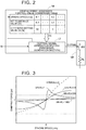
- FIG. 2 is a block diagram that illustrates configurations of the resistance value control section 16 and the variable resistor VR according to the first embodiment.
- the resistance value control section 16 has a conversion table (for example, a stroke speed resistance control value conversion table) and a control signal generation section 17.
- the stroke speed resistance control value conversion table shows a relationship between the speed of the movable shaft of the motor 20 and a resistance value of the variable resistor.
- a duty ratio setting value of a pulse width modulation (PWM) signal is described as a resistance control value for realizing the resistance value of the variable resistor VR that corresponds to the speed of the movable shaft of the motor 20.
- PWM pulse width modulation
- the control signal generation section 17 refers to the conversion table by using the stroke speed measured value Sv obtained from the motor 20 and outputs a load resistance value setting signal (for example, the PWM signal) used to set the resistance value of the variable resistor to a value corresponding to the movable speed of the movable shaft of the motor 20. More specifically, the control signal generation section 17 reads a duty ratio setting value DS that corresponds to the stroke speed measured value Sv obtained from the motor 20, and changes the duty ratio of the output PWM signal.
- a load resistance value setting signal for example, the PWM signal
- variable resistor VR has a load resistor RL and a switch SW.
- the switch SW is connected in series with the load resistor RL.
- the load resistor RL is a resistor whose resistance value is determined in advance.
- the suspension device 1 In the suspension device 1 according to the first embodiment, opened-closed states of the switch SW of the variable resistor VR are switched by the PWM signal output by the control signal generation section 17. In this way, the resistance value of the variable resistor VR is changed on a time axis. That is, the load resistor RL becomes effective when the switch SW is in the closed state, and the load resistor RL becomes void when the switch SW is in the opened state. Accordingly, the suspension device 1 according to the first embodiment changes the resistance value of the variable resistor VR by changing a period in which the load resistor RL becomes effective by the PWM signal.
- the resistance value of the variable resistor VR becomes the resistance value that is twice as large as the resistance value of the load resistor RL.
- the duty ratio of the PWM signal is 5%
- the resistance value of the variable resistor VR becomes the resistance value that is 20 times as large as the resistance value of the load resistor RL.
- the duty ratio of the PWM signal is 100%
- the resistance value of the variable resistor VR becomes the resistance value that is equal to the resistance value of the load resistor RL.
- the resistance value control section 16 generates the PWM signal such that the duty ratio is reduced as the resistance value of the variable resistor VR is increased.
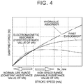
- FIG. 3 is a graph that illustrates the damping force of the absorber in a case where the resistance value is changed in the suspension device 1 according to the first embodiment. Note that FIG. 3 shows the damping force of a hydraulic absorber as an ideal value of the damping force generated in the motor 20. As shown in FIG. 3 , in a stroke speed range of the movable shaft of the motor 20 that is assumed in the suspension device 1, the damping force of the hydraulic absorber has a characteristic of being simply increased.
- a peak value of the damping force differs by a magnitude of the resistance value of the variable resistor VR. More specifically, when the motor 20 is used as the absorber, the stroke speed at which the damping force becomes the largest is increased as the resistance value of the variable resistor VR is increased.
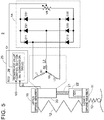
- FIG. 4 is a graph that illustrates a damping characteristic of the absorber of the suspension device 1 according to the first embodiment.
- a certain speed for example, a normal use range where a frequency of use is high as an operation situation of the suspension device 1
- the resistance value of the variable resistor VR is fixed to the certain value. In this way, in the suspension device 1 according to the first embodiment, ride quality for a user of the vehicle is improved.
- the suspension device 1 in a region where the speed of the movable shaft of the motor 20 is higher than the certain speed as the operation situation of the suspension device 1 (for example, a high-speed range where a separating operation speed between the upper spring member 10 and the lower spring member 11 is high while the frequency of the use is low as the operation situation of the suspension device 1), the resistance value of the variable resistor VR is changed to realize the largest damping force.
- the suspension device 1 according to the first embodiment can reduce width in which the damping force is saturated and a damping force characteristic deviates from that of the hydraulic absorber when the resistance value of the variable resistor VR is fixed.
- the resistance value control section 16 controls the variable resistor VR such that the resistance value of the variable resistor VR is increased in accordance with a magnitude of the speed of the movable shaft of the motor 20. In this way, a saturated state of the damping force of the motor 20, which is caused by the variable resistor VR, can be avoided, and the damping force of the motor 20 can be increased to fall within the region where the speed of the movable shaft of the motor 20 is high.
- the damping characteristic of the absorber can be brought close to the ideal damping characteristic of the hydraulic absorber.
- the duty ratio of the load resistance value setting signal Cr which controls the resistance value of the variable resistor VR, is determined by referring to the conversion table.
- the duty ratio of the load resistance value setting signal Cr can be changed at a high speed.
- the movable speed of the movable shaft of the motor 20 is changed in the suspension device from time to time, it is preferred to change the duty ratio at the high speed. That is, the damping force can be maintained in a high state by changing the duty ratio at the high speed.
- the resistance value of the variable resistor VR is changed on the basis of an opened-closed ratio of the switch SW, which is provided in series with the load resistor RL. In this way, in the suspension device 1 according to the first embodiment, an open-circuit scale of the circuit, which realizes the variable resistor VR, can be reduced, and the switching speed of the resistance value can be improved.
- a description will be made on a suspension device 2 as a different embodiment of the suspension device 1. Note that, in the description of the suspension device 2 according to the second embodiment, components that have been described in the first embodiment will be denoted by the same reference numerals as those in the first embodiment and the description thereon will not be made.
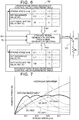
- FIG. 5 is a block diagram of a configuration of the suspension device according to the second embodiment.
- the electronic control circuit 15 of the suspension device 1 according to the first embodiment is changed to an electronic control circuit 25.
- the electronic control circuit 25 has a load control section (for example, a resistance value control section 26).
- the resistance value control section 26 switches an operation mode between a first operation mode and a second operation mode in accordance with a mode switching signal MD received from outside.
- the resistance value control section 26 controls the resistance value of the variable resistor VR such that the resistance value of the variable resistor VR is increased as the speed of the movable shaft of the motor 20 is increased.
- the resistance value control section 26 controls the resistance value of the variable resistor VR such that the damping force in the variable resistor VR becomes the largest for the speed of the movable shaft of the motor 20.
- FIG. 6 is a block diagram of configurations of the resistance value control section 26 and the variable resistor VR according to the second embodiment.
- the resistance value control section 26 has a first conversion table (for example, a first stroke speed resistance control value conversion table), a second conversion table (for example, a second stroke speed resistance control value conversion table), and a control signal generation section 27.
- the first stroke speed resistance control value conversion table is the same as the stroke speed resistance control value conversion table in the first embodiment. More specifically, the first stroke speed resistance control value conversion table is provided for the first operation mode and shows a relationship between the speed of the movable shaft of the motor 20 and the resistance value of the variable resistor VR. The second stroke speed resistance control value conversion table is provided for the second operation mode and shows a relationship between the speed of the movable shaft of the motor 20 and the resistance value of the variable resistor VR.
- the first stroke speed resistance control value conversion table a relationship between such a speed that the resistance value of the variable resistor VR is increased along with the increase in the speed of the movable shaft and a duty ratio setting value DS1 in a region where the speed of the movable shaft of the motor 20 is equal to or higher than a certain speed is described.
- the second stroke speed resistance control value conversion table such a relationship between the speed of the movable shaft and a duty ratio setting value DS2 that the damping force generated in the motor 20 becomes the largest for the speed of the movable shaft regardless of the speed of the movable shaft of the motor 20 is described.
- the control signal generation section 27 reads the duty ratio setting value for realizing the speed of the movable shaft and the resistance value of the variable resistor VR from either one of the first stroke speed resistance control value conversion table and the second stroke speed resistance control value conversion table in accordance with the mode switching signal MD and generates the PWM signal that has the duty ratio corresponding to the read duty ratio setting value.
- FIG. 7 is a graph that illustrates the damping characteristic of the absorber according to the second embodiment.
- Sv1 to Sv4 are shown as the stroke speeds, at each of which the resistance value of the variable resistor VR is changed.
- the resistance value of the variable resistor VR is changed to realize the largest damping force for each of the speeds of the movable shaft of the motor 20 (for example, the stroke speeds Sv1 to Sv4).
- switching timing of the resistance value of the variable resistor VR corresponds to the stroke speed at which damping force curves DC corresponding to the stroke speeds cross each other.
- the suspension device 2 according to the second embodiment has such a characteristic that the damping force of the absorber is changed along a ridge of the damping force curve DC that differs by the resistance value of the variable resistor VR.
- the resistance value of the variable resistor VR is changed to realize the largest damping force regardless of the speed of the movable shaft of the motor 20.
- the regenerative power generated in the motor 20 can most efficiently be recovered.
- a power regeneration circuit for example, an AC-DC conversion circuit
- a resistance value of a portion in this power regeneration circuit that receives the regenerative power of the motor 20 has to be changed in a similar manner to that of the variable resistor VR shown in FIG. 5 and FIG. 6 .
- a description will be made on a suspension device 3 as another embodiment of the suspension device 1. Note that, in the description of the suspension device 3 according to the third embodiment, components that have been described in the first embodiment will be denoted by the same reference numerals as those in the first embodiment and the description thereon will not be made.
- FIG. 8 is a block diagram of a configuration of the suspension device according to the third embodiment.
- the power consumption circuit 14 of the suspension device 1 according to the first embodiment is replaced with a power consumption circuit 34
- the electronic control circuit 15 is replaced with an electronic control circuit 35.
- the power consumption circuit 34 of the suspension device 3 according to the third embodiment includes a buck-boost circuit 41 as a specific example of a regenerative power circuit realized by the variable resistor VR of the suspension device 2 according to the second embodiment.
- the power consumption circuit 34 has the buck-boost circuit 41 and a secondary battery (for example, a battery 44).
- the power consumption circuit 34 also has: a voltage measurement device 42 that measures a voltage value used for control of the battery 44; and a current measurement device 43 that measures a current value.
- the buck-boost circuit 41 steps up or steps down a motor voltage (for example, a voltage difference between the cathodes of the diodes D11, D21, D31 and the anodes of the diodes D12, D22, D32) generated in the motor 20 on the basis of the load resistance value setting signal Cr and generates an output voltage Vout with a constant voltage value. Then, the output voltage Vout of the buck-boost circuit 41 is applied to the battery 44, and the regenerative power generated in the motor 20 is stored therein.
- a motor voltage for example, a voltage difference between the cathodes of the diodes D11, D21, D31 and the anodes of the diodes D
- the electronic control circuit 35 includes the load control section (for example, a buck-boost control section 36).
- the buck-boost control section 36 receives the speed of the movable shaft of the motor 20 as the stroke speed measured value Sv and outputs the load resistance value setting signal Cr with the duty ratio that corresponds to the received stroke speed measured value Sv.
- This buck-boost control section 36 has a control signal generation section and a conversion table as shown in FIG. 2 , for example, and outputs the load resistance value setting signal Cr with the duty ratio that corresponds to the stroke speed measured value Sv provided by the motor 20.
- This conversion table shows a correlation between the stroke speed and the duty ratio as shown in FIG. 2 , for example.
- FIG. 9 is a circuit diagram of the buck-boost circuit of the suspension device 3 according to the third embodiment. As shown in FIG. 9 , the buck-boost circuit 41 according to the third embodiment has switches SW1, SW2, capacitors C1, C2, a coil L1, and diodes Da to Dc.
- a wire to which the cathodes of the diodes D11, D21, D31 are connected, a wire connected to a positive electrode of the battery 44 among output wires of the buck-boost circuit 41, and a wire to which the anodes of the diodes D12, D22, D32 are connected are respectively referred to as an input positive electrode wire, an output positive electrode wire, and a negative electrode wire.
- a negative electrode of the battery 44 is connected to the negative electrode wire.
- a motor voltage Vin that is generated by the regenerative operation of the motor 20 is generated between the input positive electrode wire and the negative electrode wire, and this motor voltage Vin is received by the buck-boost circuit 41.
- the buck-boost circuit 41 generates the output voltage Vout between the output positive electrode wire and the negative electrode wire.
- the capacitor C 1 is connected between the input positive electrode wire and the negative electrode wire.
- One end of the switch SW1 is connected to the input positive electrode wire.
- An anode of the diode Da is connected to the other end of the switch SW1, and a cathode of the diode Da is connected to the one end of the switch SW1.
- An anode of the diode Db is connected to the negative electrode wire.
- a cathode of the diode Db is connected to the other end of the switch SW1.
- An opened-closed state of the switch SW1 is controlled by the load resistance value setting signal Cr.
- One end of the coil L1 is connected to the other end of the switch SW1.
- One end of the switch SW2 is connected to the other end of the coil L1.
- the other end of the switch SW2 is connected to the negative electrode.
- An anode of the diode Dc is connected to the other end of the coil L1.
- a cathode of the diode Dc is connected to the output positive electrode wire.
- the capacitor C1 is connected between the output positive electrode wire and the negative electrode wire.
- a resistor R1 is connected between the output positive electrode wire and the negative electrode wire.
- Each parameter of the buck-boost circuit 41 is set such that the motor voltage Vin and the output voltage Vout becomes an equal voltage when the duty ratio of the load resistance value setting signal Cr is 50%.
- the buck-boost circuit 41 steps up the output voltage Vout to be a higher voltage than the motor voltage Vin.
- the buck-boost circuit 41 steps down the output voltage Vout to be a lower voltage than the motor voltage Vin.
- FIG. 10 is a graph that illustrates a damping characteristic of an absorber according to the third embodiment.
- the larger damping force can be obtained as the duty ratio is increased.
- the larger damping force can be obtained as the duty ratio is reduced.
- the duty ratio is changed in accordance with the stroke speed so as to obtain the target damping force.
- the duty ratio is changed to 96.5%, 93.5%, 88%, 79%, 92%, 60%, 45%, and 33%. In this way, the damping force that is equal to the target damping force is obtained.
- FIG. 11 is a graph that illustrates the regenerative power of the absorber according to the third embodiment.
- the power that can be regenerated is increased as the stroke speed of the motor 20 is increased.
- the suspension device 3 according to the third embodiment has a significant tendency that a larger amount of the regenerative power can be obtained by reducing the duty ratio of the load resistance value setting signal Cr as the stroke speed of the motor 20 is increased.
- FIG. 11 shows an ideal value of the power that can be regenerated with the target damping force.
- a difference is observed between this regenerative power ideal value and the actually obtained regenerative power, and it is considered that this difference is resulted from conversion efficiency, loss, or the like in the buck-boost circuit 41.
- the power consumption circuit 34 includes the buck-boost circuit 41 and the battery 44, which is charged with the regenerative power. In this way, the battery 44 can be charged with the regenerative power that is generated to dampen a rotational force of the motor 20.
- a suspension device has: a spring (12) interposed between an upper member (10) and a lower member (11); a motor (20) provided in juxtaposition with the spring (12) to generate power in accordance with a movable speed of the movable shaft that can move in accordance with a separating operation of the upper member (10) and the lower member (11); a power consumption circuit (14) including a variable resistor VR that changes a damping force generated in the motor (20) by consuming the power generated in the motor (20); and a resistance value control section (16) that controls the variable resistor (VR) such that a resistance value of the variable resistor (VR) is increased along with an increase in a movable speed of the movable shaft.
Landscapes
- Engineering & Computer Science (AREA)
- Mechanical Engineering (AREA)
- Vehicle Body Suspensions (AREA)
- Physics & Mathematics (AREA)
- General Engineering & Computer Science (AREA)
- Electromagnetism (AREA)
- Acoustics & Sound (AREA)
- Aviation & Aerospace Engineering (AREA)
Abstract
A suspension device according to one aspect of the invention has: a spring (12) interposed between an upper member (10) and a lower member (11); a motor (20) provided in juxtaposition with the spring (12) to generate power in accordance with a movable speed of the movable shaft that can move in accordance with a separating operation of the upper member (10) and the lower member (11); a power consumption circuit (14) including a variable resistor VR that changes a damping force generated in the motor (20) by consuming the power generated in the motor (20); and a resistance value control section (16) that controls the variable resistor (VR) such that a resistance value of the variable resistor (VR) is increased along with an increase in a movable speed of the movable shaft.
Description
- The invention relates to a suspension device. In particular, the invention relates to a suspension device including an electromagnetic absorber that is provided in juxtaposition with a spring of a suspension and converts kinetic energy, which is generated by approaching-separating motion between a spring upper portion and a spring lower portion, to electrical energy, for example.
- In recent years, as a suspension device for a vehicle, an electromagnetic suspension device including an electromagnetic absorber that uses an electromagnetic motor to generate regenerative power and dampens a force in a direction in which a spring upper portion and a spring lower portion approach or separate from each other by a regenerative operation has been examined. One example of the suspension device including such an electromagnetic absorber is disclosed in Japanese Patent Application Publication No.
2010-228579 JP 2010-228579 A - A suspension system described in
JP 2010-228579 A - However, due to a characteristic of the motor, in the electromagnetic shock absorber, a damping force may be saturated in a speed range where a stroke speed of a movable shaft causing an operation of the movable shaft of the absorber becomes equal to or higher than a specified speed.
- The invention provides a suspension device capable of increasing a damping force in a speed range where the damping force is saturated due to a characteristic of a motor.
- A suspension device according to one aspect of the invention includes: a spring provided between an upper member and a lower member; a motor provided in juxtaposition with the spring, the motor being configured to generate power in accordance with a speed at which a movable shaft is operated, the movable shaft being movable in accordance with operations of the upper member and the lower member in an expansion-contraction direction of the spring; a power consumption circuit including a variable load circuit, the variable load circuit being configured to generate a damping force in the motor by consuming the power generated in the motor and to change the damping force; and a load control section configured to control the variable load circuit such that consumed power by the variable load circuit is increased along with an increase in a speed of the movable shaft.
- According to the above aspect, a resistance value of variable resistor in the power consumption circuit is increased along with an increase in an operation speed of the motor. As a result, the consumed power in the power consumption circuit is increased. Thus, a reduction in the damping force can be suppressed in a speed range where the damping force is saturated due to a characteristic of the motor.
- In the above aspect, the load control section may be configured to maintain a resistance value of the variable load circuit to a specified value when the speed of the movable shaft is equal to or lower than a specified speed.
- According to the above configuration, when the speed of the movable shaft of the motor is equal to or lower than the specified speed, the resistance value of the variable resistor is set to a fixed resistance value, with which a difference between the damping force and a reference damping force serving as a reference of the damping force falls within a certain range. Note that, when the speed of the movable shaft of the motor is equal to or higher than the specified speed, the damping force that is saturated with the fixed resistance value is compensated by changing the resistance value of the variable resistor. In this way, a characteristic of the suspension device can be brought close to an ideal state.
- In the above aspect, the load control section may have a conversion table that indicates a relationship between the speed of the movable shaft and a resistance value of the variable load circuit, and the load control section is configured to output a load resistance value setting signal based on the conversion table, the load resistance value setting signal being used to set a resistance value of the variable load circuit to a value corresponding to the speed of the movable shaft.
- According to the above configuration, a value of the load resistance value setting signal can be determined at a high speed.
- In the above aspect, the variable load circuit may have: a load resistor that has a predetermined resistance value; and a switch connected in series with the load resistor, and the load control section may have a control signal generation section that is configured to generate a pulse width modulation signal such that a duty ratio is reduced as a resistance value of the variable load circuit is increased, the pulse width modulation signal being used to switch an opened- closed state of the switch.
- According to the above configuration, the resistance value on a time axis can be changed. Thus, a scale of the circuit can be reduced, and a response speed of a change in the resistance value can be increased.
- In the above aspect, the load control section may be configured to switch an operation between a first operation mode and a second operation mode in accordance with a mode switching signal provided from outside. The load control section may be configured to, in the first operation mode, the load control section may be configured to control a resistance value of the variable load circuit such that the resistance value of the variable load circuit is increased along with an increase in the speed of the movable shaft, and in the second operation mode, control the resistance value of the variable load circuit such that the damping force in the variable load circuit becomes the largest for the speed of the movable shaft.
- According to the above configuration, the operation mode in which a regenerative amount of the power generated by the motor is maximized can be added.
- In the above aspect, the load control section may have: a first conversion table that indicates a relationship between the speed of the movable shaft and the resistance value of the variable load circuit, the first conversion table being provided for the first operation mode; a second conversion table that indicates a relationship between the speed of the movable shaft and the resistance value of the variable load circuit, the second conversion table being provided for the second operation mode; and a control signal generation section that is configured to read a duty ratio setting value used to realize the speed of the movable shaft and the resistance value of the variable load circuit from either one of the first conversion table and the second conversion table in accordance with the mode switching signal and to generate a pulse width modulation signal with the duty ratio that corresponds to the read duty ratio setting value.
- According to the above configuration, a value of the load resistance value setting signal can be determined at a high speed.
- In the above aspect, the load control section may have a control signal generation section configured to generate a load resistance value setting signal including a duty ratio that corresponds to the speed of the movable shaft, and the variable load circuit may include: a buck-boost circuit that is configured to step up or step down a motor voltage generated in the motor based on the load resistance value setting signal to generate an output voltage with a constant voltage value; and a secondary battery, to which the output voltage is applied, and to which regenerative power generated in the motor is stored.
- According to the above configuration, the power generated by the motor can be regenerated to the secondary battery.
- In the above aspect, the duty ratio of the load resistance value setting signal may be set such that the damping force generated by the variable load circuit by consuming the power generated in the motor becomes a target damping force.
- According to the above configuration, while the power generated in the motor is regenerated to the secondary battery, a damping force characteristic of the suspension device can realize the target damping force.
- The suspension device according to the invention can increase the damping force in a speed range where the damping force is saturated due to a characteristic of the motor.
- Features, advantages, and technical and industrial significance of exemplary embodiments of the invention will be described below with reference to the accompanying drawings, in which like numerals denote like elements, and wherein:
-
FIG. 1 is a block diagram that illustrates a configuration of a suspension device according to a first embodiment; -
FIG. 2 is a block diagram of configurations of a resistance value control section and a variable resistor according to the first embodiment; -
FIG. 3 is a graph that illustrates a damping force of an absorber in a case where the resistance value is changed in the suspension device according to the first embodiment; -
FIG. 4 is a graph that illustrates a damping characteristic of the absorber according to the first embodiment; -
FIG. 5 is a block diagram of a configuration of a suspension device according to a second embodiment; -
FIG. 6 is a block diagram of configurations of a resistance value control section and a variable resistor according to the second embodiment; -
FIG. 7 is a graph that illustrates a damping characteristic of an absorber according to the second embodiment; -
FIG. 8 is a block diagram of a configuration of a suspension device according to a third embodiment; -
FIG. 9 is a circuit diagram of a buck-boost circuit of the suspension device according to the third embodiment; -
FIG. 10 is a graph that illustrates a damping characteristic of an absorber according to the third embodiment; and -
FIG. 11 is a graph that illustrates regenerative power of the absorber according to the third embodiment. - A description will hereinafter be made on embodiments of the invention with reference to the drawings. For clarification of the description, the following description and the drawings will appropriately be omitted or simplified. In each of the drawings, the same element is denoted by the same reference numeral, and an overlapping description thereon will not be made when necessary.
- First, a description will be made on a configuration of a
suspension device 1 according to a first embodiment.FIG. 1 is a block diagram that illustrates the configuration of thesuspension device 1 according to the first embodiment. - As shown in
FIG. 1 , thesuspension device 1 according to the first embodiment has an upper member (for example, an upper spring member 10), a lower member (for example, a lower spring member 11), aspring 12, atire 13, amotor 20, aball screw 21, ascrew support member 22, apower consumption circuit 14, and anelectronic control circuit 15. In thesuspension device 1 according to the first embodiment, themotor 20, theball screw 21, and thescrew support member 22 constitute an electromagnetic absorber. - The
upper spring member 10 is connected to a vehicle body, for example. Thelower spring member 11 is attached to a suspension arm that is attached to the vehicle, for example, and receives a force from thetire 13. InFIG. 1 , thetire 13 is shown as a model that is configured by including a spring and a roller. Thespring 12 is provided in a manner to be held between theupper spring member 10 and thelower spring member 11. - The
motor 20 is provided in juxtaposition with thespring 12 and generates power in accordance with an operation speed of a movable shaft (hereinafter also referred to as a stroke speed) that is operated in accordance with operations of theupper spring member 10 and thelower spring member 11 in an expansion-contraction direction of thespring 12. Themotor 20 generates a current in accordance with motion of the movable shaft and thereby generates a damping force. Theball screw 21 and thescrew support member 22 constitute an operation conversion mechanism. This operation conversion mechanism is disposed in series with themotor 20 between theupper spring member 10 and thelower spring member 11. The operation conversion mechanism converts an approaching-separating operation between theupper spring member 10 and thelower spring member 11 to the motion of the movable shaft of themotor 20. In the electromagnetic absorber according to the first embodiment, when theupper spring member 10 and thelower spring member 11 perform the approaching-separating operation, thescrew support member 22 causes rotation of theball screw 21 in accordance with said approaching-separating operation, and the movable shaft of themotor 20, which is coupled to theball screw 21, rotates in an orthogonal direction to an approaching-separating direction. -
FIG. 1 also shows a circuit model of themotor 20. Themotor 20 is a three-phase motor, for example, and can be illustrated as a model that has coils L1 to L3 and resistors R1 to R3, one ends of which are respectively connected to one ends of the coils L1 to L3, in which the other ends of the resistors R1 to R3 are connected, and in which the generated current is output from each of the other ends of the coils L1 to L3. - The
power consumption circuit 14 converts the generated current output from themotor 20 to heat. That is, thepower consumption circuit 14 converts electrical energy generated by a regenerative operation of themotor 20 to thermal energy. In addition, thepower consumption circuit 14 consumes power generated in themotor 20 and thereby changes the damping force generated in themotor 20. Thepower consumption circuit 14 has diodes D11, D12, D21, D22, D31, D32 and a variable load circuit (for example, a variable resistor VR). - The diode D11 and the diode D12 are connected in series between both ends of the variable resistor VR. The other end of the coil L1 is connected to a connection point at which an anode of the diode D11 and a cathode of the diode D12 are connected. The diode D21 and the diode D22 are connected in series between both of the ends of the variable resistor VR. The other end of the coil L2 is connected to a connection point at which an anode of the diode D21 and a cathode of the diode D22 are connected. The diode D31 and the diode D32 are connected in series between both of the ends of the variable resistor VR. The other end of the coil L3 is connected to a connection point at which an anode of the diode D31 and a cathode of the diode D32 are connected.
- The
electronic control circuit 15 is an integrated circuit such as a microcontroller unit (MCU) and includes: an arithmetic circuit capable of executing a program; and a peripheral circuit having various functions and used by the arithmetic circuit. In an example shown inFIG. 1 , theelectronic control circuit 15 includes a load control section (for example, a resistance value control section 16). The resistancevalue control section 16 controls the variable resistor VR such that a resistance value of the variable resistor VR is increased as a movable speed of the movable shaft of themotor 20 is increased. The resistancevalue control section 16 receives a stroke speed measured value Sv and outputs a load resistance value setting signal Cr used to set the resistance value of the variable resistor VR to the resistance value that corresponds to the stroke speed of the movable shaft indicated by said stroke speed measured value Sv. - Here, a detailed description will be made on the resistance
value control section 16 and the variable resistor VR.FIG. 2 is a block diagram that illustrates configurations of the resistancevalue control section 16 and the variable resistor VR according to the first embodiment. - As shown in
FIG. 2 , the resistancevalue control section 16 has a conversion table (for example, a stroke speed resistance control value conversion table) and a controlsignal generation section 17. The stroke speed resistance control value conversion table shows a relationship between the speed of the movable shaft of themotor 20 and a resistance value of the variable resistor. In addition, in the stroke speed resistance control value conversion table, a duty ratio setting value of a pulse width modulation (PWM) signal is described as a resistance control value for realizing the resistance value of the variable resistor VR that corresponds to the speed of the movable shaft of themotor 20. - The control
signal generation section 17 refers to the conversion table by using the stroke speed measured value Sv obtained from themotor 20 and outputs a load resistance value setting signal (for example, the PWM signal) used to set the resistance value of the variable resistor to a value corresponding to the movable speed of the movable shaft of themotor 20. More specifically, the controlsignal generation section 17 reads a duty ratio setting value DS that corresponds to the stroke speed measured value Sv obtained from themotor 20, and changes the duty ratio of the output PWM signal. - In addition, as shown in
FIG. 2 , the variable resistor VR has a load resistor RL and a switch SW. The switch SW is connected in series with the load resistor RL. The load resistor RL is a resistor whose resistance value is determined in advance. - In the
suspension device 1 according to the first embodiment, opened-closed states of the switch SW of the variable resistor VR are switched by the PWM signal output by the controlsignal generation section 17. In this way, the resistance value of the variable resistor VR is changed on a time axis. That is, the load resistor RL becomes effective when the switch SW is in the closed state, and the load resistor RL becomes void when the switch SW is in the opened state. Accordingly, thesuspension device 1 according to the first embodiment changes the resistance value of the variable resistor VR by changing a period in which the load resistor RL becomes effective by the PWM signal. More specifically, when the duty ratio of the PWM signal is 50%, the resistance value of the variable resistor VR becomes the resistance value that is twice as large as the resistance value of the load resistor RL. When the duty ratio of the PWM signal is 5%, the resistance value of the variable resistor VR becomes the resistance value that is 20 times as large as the resistance value of the load resistor RL. When the duty ratio of the PWM signal is 100%, the resistance value of the variable resistor VR becomes the resistance value that is equal to the resistance value of the load resistor RL. - In the
suspension device 1 according to the first embodiment, the resistancevalue control section 16 generates the PWM signal such that the duty ratio is reduced as the resistance value of the variable resistor VR is increased. - Next, a description will be made on a relationship between the resistance value of the variable resistor VR and the damping force generated in the
motor 20.FIG. 3 is a graph that illustrates the damping force of the absorber in a case where the resistance value is changed in thesuspension device 1 according to the first embodiment. Note thatFIG. 3 shows the damping force of a hydraulic absorber as an ideal value of the damping force generated in themotor 20. As shown inFIG. 3 , in a stroke speed range of the movable shaft of themotor 20 that is assumed in thesuspension device 1, the damping force of the hydraulic absorber has a characteristic of being simply increased. On the other hand, when themotor 20 is used as the absorber, a peak value of the damping force differs by a magnitude of the resistance value of the variable resistor VR. More specifically, when themotor 20 is used as the absorber, the stroke speed at which the damping force becomes the largest is increased as the resistance value of the variable resistor VR is increased. - Next,
FIG. 4 is a graph that illustrates a damping characteristic of the absorber of thesuspension device 1 according to the first embodiment. As shown inFIG. 4 , in thesuspension device 1 according to the first embodiment, in a region where the speed of the movable shaft of themotor 20 is equal to or lower than a certain speed (for example, a normal use range where a frequency of use is high as an operation situation of the suspension device 1) as an operation situation of thesuspension device 1, the resistance value of the variable resistor VR is fixed to the certain value. In this way, in thesuspension device 1 according to the first embodiment, ride quality for a user of the vehicle is improved. - Meanwhile, in the
suspension device 1 according to the first embodiment, in a region where the speed of the movable shaft of themotor 20 is higher than the certain speed as the operation situation of the suspension device 1 (for example, a high-speed range where a separating operation speed between theupper spring member 10 and thelower spring member 11 is high while the frequency of the use is low as the operation situation of the suspension device 1), the resistance value of the variable resistor VR is changed to realize the largest damping force. In this way, thesuspension device 1 according to the first embodiment can reduce width in which the damping force is saturated and a damping force characteristic deviates from that of the hydraulic absorber when the resistance value of the variable resistor VR is fixed. - From the above description, in the
suspension device 1 according to the first embodiment, the resistancevalue control section 16 controls the variable resistor VR such that the resistance value of the variable resistor VR is increased in accordance with a magnitude of the speed of the movable shaft of themotor 20. In this way, a saturated state of the damping force of themotor 20, which is caused by the variable resistor VR, can be avoided, and the damping force of themotor 20 can be increased to fall within the region where the speed of the movable shaft of themotor 20 is high. - In the
suspension device 1 according to the first embodiment, when the speed of the movable shaft of themotor 20 is equal to or lower than the certain speed, the resistance value of the variable resistor is maintained to be constant. In this way, in thesuspension device 1 according to the first embodiment, the damping characteristic of the absorber can be brought close to the ideal damping characteristic of the hydraulic absorber. - In the
suspension device 1 according to the first embodiment, when the resistance value of the variable resistor VR is controlled in accordance with the speed of the movable shaft of themotor 20, the duty ratio of the load resistance value setting signal Cr, which controls the resistance value of the variable resistor VR, is determined by referring to the conversion table. In this way, in thesuspension device 1 according to the first embodiment, the duty ratio of the load resistance value setting signal Cr can be changed at a high speed. In particular, because the movable speed of the movable shaft of themotor 20 is changed in the suspension device from time to time, it is preferred to change the duty ratio at the high speed. That is, the damping force can be maintained in a high state by changing the duty ratio at the high speed. - In the
suspension device 1 according to the first embodiment, the resistance value of the variable resistor VR is changed on the basis of an opened-closed ratio of the switch SW, which is provided in series with the load resistor RL. In this way, in thesuspension device 1 according to the first embodiment, an open-circuit scale of the circuit, which realizes the variable resistor VR, can be reduced, and the switching speed of the resistance value can be improved. - In a second embodiment, a description will be made on a
suspension device 2 as a different embodiment of thesuspension device 1. Note that, in the description of thesuspension device 2 according to the second embodiment, components that have been described in the first embodiment will be denoted by the same reference numerals as those in the first embodiment and the description thereon will not be made. -
FIG. 5 is a block diagram of a configuration of the suspension device according to the second embodiment. As shown inFIG. 5 , in thesuspension device 2 according to the second embodiment, theelectronic control circuit 15 of thesuspension device 1 according to the first embodiment is changed to anelectronic control circuit 25. Theelectronic control circuit 25 has a load control section (for example, a resistance value control section 26). The resistancevalue control section 26 switches an operation mode between a first operation mode and a second operation mode in accordance with a mode switching signal MD received from outside. In the first operation mode, the resistancevalue control section 26 controls the resistance value of the variable resistor VR such that the resistance value of the variable resistor VR is increased as the speed of the movable shaft of themotor 20 is increased. In the second operation mode, the resistancevalue control section 26 controls the resistance value of the variable resistor VR such that the damping force in the variable resistor VR becomes the largest for the speed of the movable shaft of themotor 20. - Here, a detailed description will be made on the resistance
value control section 26.FIG. 6 is a block diagram of configurations of the resistancevalue control section 26 and the variable resistor VR according to the second embodiment. As shown inFIG. 6 , the resistancevalue control section 26 has a first conversion table (for example, a first stroke speed resistance control value conversion table), a second conversion table (for example, a second stroke speed resistance control value conversion table), and a controlsignal generation section 27. - The first stroke speed resistance control value conversion table is the same as the stroke speed resistance control value conversion table in the first embodiment. More specifically, the first stroke speed resistance control value conversion table is provided for the first operation mode and shows a relationship between the speed of the movable shaft of the
motor 20 and the resistance value of the variable resistor VR. The second stroke speed resistance control value conversion table is provided for the second operation mode and shows a relationship between the speed of the movable shaft of themotor 20 and the resistance value of the variable resistor VR. - More specifically, in the first stroke speed resistance control value conversion table, a relationship between such a speed that the resistance value of the variable resistor VR is increased along with the increase in the speed of the movable shaft and a duty ratio setting value DS1 in a region where the speed of the movable shaft of the
motor 20 is equal to or higher than a certain speed is described. Meanwhile, in the second stroke speed resistance control value conversion table, such a relationship between the speed of the movable shaft and a duty ratio setting value DS2 that the damping force generated in themotor 20 becomes the largest for the speed of the movable shaft regardless of the speed of the movable shaft of themotor 20 is described. - The control
signal generation section 27 reads the duty ratio setting value for realizing the speed of the movable shaft and the resistance value of the variable resistor VR from either one of the first stroke speed resistance control value conversion table and the second stroke speed resistance control value conversion table in accordance with the mode switching signal MD and generates the PWM signal that has the duty ratio corresponding to the read duty ratio setting value. - Next, a description will be made on the damping characteristic of the absorber in the
suspension device 2 according to the second embodiment.FIG. 7 is a graph that illustrates the damping characteristic of the absorber according to the second embodiment. In an example shown inFIG. 7 , Sv1 to Sv4 are shown as the stroke speeds, at each of which the resistance value of the variable resistor VR is changed. As shown inFIG. 7 , in thesuspension device 2 according to the second embodiment, the resistance value of the variable resistor VR is changed to realize the largest damping force for each of the speeds of the movable shaft of the motor 20 (for example, the stroke speeds Sv1 to Sv4). In addition, in thesuspension device 2 according to the second embodiment, switching timing of the resistance value of the variable resistor VR corresponds to the stroke speed at which damping force curves DC corresponding to the stroke speeds cross each other. In this way, thesuspension device 2 according to the second embodiment has such a characteristic that the damping force of the absorber is changed along a ridge of the damping force curve DC that differs by the resistance value of the variable resistor VR. - From the above description, in the
suspension device 2 according to the second embodiment, the resistance value of the variable resistor VR is changed to realize the largest damping force regardless of the speed of the movable shaft of themotor 20. In this way, in thesuspension device 2 according to the second embodiment, the regenerative power generated in themotor 20 can most efficiently be recovered. Note that, in order to recover the regenerative power generated in themotor 20, a power regeneration circuit (for example, an AC-DC conversion circuit) is used, and a resistance value of a portion in this power regeneration circuit that receives the regenerative power of themotor 20 has to be changed in a similar manner to that of the variable resistor VR shown inFIG. 5 andFIG. 6 . - In a third embodiment, a description will be made on a
suspension device 3 as another embodiment of thesuspension device 1. Note that, in the description of thesuspension device 3 according to the third embodiment, components that have been described in the first embodiment will be denoted by the same reference numerals as those in the first embodiment and the description thereon will not be made. -
FIG. 8 is a block diagram of a configuration of the suspension device according to the third embodiment. As shown inFIG. 8 , in thesuspension device 3 according to the third embodiment, thepower consumption circuit 14 of thesuspension device 1 according to the first embodiment is replaced with apower consumption circuit 34, and theelectronic control circuit 15 is replaced with anelectronic control circuit 35. That is, thepower consumption circuit 34 of thesuspension device 3 according to the third embodiment includes a buck-boost circuit 41 as a specific example of a regenerative power circuit realized by the variable resistor VR of thesuspension device 2 according to the second embodiment. - As the variable load circuit, the
power consumption circuit 34 has the buck-boost circuit 41 and a secondary battery (for example, a battery 44). Thepower consumption circuit 34 also has: avoltage measurement device 42 that measures a voltage value used for control of thebattery 44; and acurrent measurement device 43 that measures a current value. The buck-boost circuit 41 steps up or steps down a motor voltage (for example, a voltage difference between the cathodes of the diodes D11, D21, D31 and the anodes of the diodes D12, D22, D32) generated in themotor 20 on the basis of the load resistance value setting signal Cr and generates an output voltage Vout with a constant voltage value. Then, the output voltage Vout of the buck-boost circuit 41 is applied to thebattery 44, and the regenerative power generated in themotor 20 is stored therein. - The
electronic control circuit 35 includes the load control section (for example, a buck-boost control section 36). The buck-boost control section 36 receives the speed of the movable shaft of themotor 20 as the stroke speed measured value Sv and outputs the load resistance value setting signal Cr with the duty ratio that corresponds to the received stroke speed measured value Sv. This buck-boost control section 36 has a control signal generation section and a conversion table as shown inFIG. 2 , for example, and outputs the load resistance value setting signal Cr with the duty ratio that corresponds to the stroke speed measured value Sv provided by themotor 20. This conversion table shows a correlation between the stroke speed and the duty ratio as shown inFIG. 2 , for example. In the conversion table provided in the buck-boost control section 36, such a duty ratio, with which the damping force, which is generated when the buck-boost circuit 41 consumes the regenerative power of themotor 20, becomes a target damping force set in accordance with the stroke speed measured value Sv, is described. - Here, a detailed description will be made on the buck-
boost circuit 41.FIG. 9 is a circuit diagram of the buck-boost circuit of thesuspension device 3 according to the third embodiment. As shown inFIG. 9 , the buck-boost circuit 41 according to the third embodiment has switches SW1, SW2, capacitors C1, C2, a coil L1, and diodes Da to Dc. Note that, in the following description, a wire to which the cathodes of the diodes D11, D21, D31 are connected, a wire connected to a positive electrode of thebattery 44 among output wires of the buck-boost circuit 41, and a wire to which the anodes of the diodes D12, D22, D32 are connected are respectively referred to as an input positive electrode wire, an output positive electrode wire, and a negative electrode wire. A negative electrode of thebattery 44 is connected to the negative electrode wire. In thesuspension device 3 according to the third embodiment, a motor voltage Vin that is generated by the regenerative operation of themotor 20 is generated between the input positive electrode wire and the negative electrode wire, and this motor voltage Vin is received by the buck-boost circuit 41. The buck-boost circuit 41 generates the output voltage Vout between the output positive electrode wire and the negative electrode wire. - The
capacitor C 1 is connected between the input positive electrode wire and the negative electrode wire. One end of the switch SW1 is connected to the input positive electrode wire. An anode of the diode Da is connected to the other end of the switch SW1, and a cathode of the diode Da is connected to the one end of the switch SW1. An anode of the diode Db is connected to the negative electrode wire. A cathode of the diode Db is connected to the other end of the switch SW1. An opened-closed state of the switch SW1 is controlled by the load resistance value setting signal Cr. - One end of the coil L1 is connected to the other end of the switch SW1. One end of the switch SW2 is connected to the other end of the coil L1. The other end of the switch SW2 is connected to the negative electrode. An anode of the diode Dc is connected to the other end of the coil L1. A cathode of the diode Dc is connected to the output positive electrode wire. The capacitor C1 is connected between the output positive electrode wire and the negative electrode wire. A resistor R1 is connected between the output positive electrode wire and the negative electrode wire.
- Each parameter of the buck-
boost circuit 41 is set such that the motor voltage Vin and the output voltage Vout becomes an equal voltage when the duty ratio of the load resistance value setting signal Cr is 50%. When the duty ratio of the load resistance value setting signal Cr becomes higher than 50%, the buck-boost circuit 41 steps up the output voltage Vout to be a higher voltage than the motor voltage Vin. Meanwhile, when the duty ratio of the load resistance value setting signal Cr becomes lower than 50%, the buck-boost circuit 41 steps down the output voltage Vout to be a lower voltage than the motor voltage Vin. - Here, a description will be made on a relationship between the duty ratio of the load resistance value setting signal Cr, which is provided to the buck-
boost circuit 41, and the damping force generated in themotor 20.FIG. 10 is a graph that illustrates a damping characteristic of an absorber according to the third embodiment. As shown inFIG. 10 , in thesuspension device 3 according to the third embodiment, in the case where the stroke speed of themotor 20 is low, the larger damping force can be obtained as the duty ratio is increased. Meanwhile, in thesuspension device 3 according to the third embodiment, in the case where the stroke speed of themotor 20 is high, the larger damping force can be obtained as the duty ratio is reduced. - Then, in the
suspension device 3 according to the third embodiment, the duty ratio is changed in accordance with the stroke speed so as to obtain the target damping force. In an example shown inFIG. 10 , along with the increase in the stroke speed, the duty ratio is changed to 96.5%, 93.5%, 88%, 79%, 92%, 60%, 45%, and 33%. In this way, the damping force that is equal to the target damping force is obtained. - Next, a description will be made on a relationship between the duty ratio of the load resistance value setting signal Cr provided to the buck-
boost circuit 41 and the regenerative power regenerated by the buck-boost circuit 41.FIG. 11 is a graph that illustrates the regenerative power of the absorber according to the third embodiment. As shown inFIG. 11 , it is understood that, in thesuspension device 3 according to the third embodiment, the power that can be regenerated is increased as the stroke speed of themotor 20 is increased. It is also understood that, thesuspension device 3 according to the third embodiment has a significant tendency that a larger amount of the regenerative power can be obtained by reducing the duty ratio of the load resistance value setting signal Cr as the stroke speed of themotor 20 is increased. Furthermore, it is understood that, also in the case where the duty ratio of the load resistance value setting signal Cr is changed to obtain the target damping force described inFIG. 10 , the power that can be regenerated is increased as the stroke speed of themotor 20 is increased.FIG. 11 shows an ideal value of the power that can be regenerated with the target damping force. In an example shown inFIG. 11 , a difference is observed between this regenerative power ideal value and the actually obtained regenerative power, and it is considered that this difference is resulted from conversion efficiency, loss, or the like in the buck-boost circuit 41. - From the above description, in the
suspension device 3 according to the third embodiment, thepower consumption circuit 34 includes the buck-boost circuit 41 and thebattery 44, which is charged with the regenerative power. In this way, thebattery 44 can be charged with the regenerative power that is generated to dampen a rotational force of themotor 20. - In the above description, the invention has specifically been described on the basis of the embodiments. However, it is needless to say that the invention is not limited to the already-mentioned embodiments and various changes can be made thereto within the scope that does not depart from the gist of the invention.
- A suspension device according to one aspect of the invention has: a spring (12) interposed between an upper member (10) and a lower member (11); a motor (20) provided in juxtaposition with the spring (12) to generate power in accordance with a movable speed of the movable shaft that can move in accordance with a separating operation of the upper member (10) and the lower member (11); a power consumption circuit (14) including a variable resistor VR that changes a damping force generated in the motor (20) by consuming the power generated in the motor (20); and a resistance value control section (16) that controls the variable resistor (VR) such that a resistance value of the variable resistor (VR) is increased along with an increase in a movable speed of the movable shaft.
Claims (8)
- A suspension device comprising:a spring (12) provided between an upper member (10) and a lower member (11);a motor (20) provided in juxtaposition with the spring (12), the motor (20) being configured to generate power in accordance with a speed at which a movable shaft is operated, the movable shaft being movable in accordance with operations of the upper member (10) and the lower member (11) in an expansion-contraction direction of the spring (12);a power consumption circuit (14) including a variable load circuit, the variable load circuit being configured to generate a damping force in the motor (20) by consuming the power generated in the motor (20) and to change the damping force; anda load control section configured to control the variable load circuit such that consumed power by the variable load circuit is increased along with an increase in a speed of the movable shaft.
- The suspension device according to claim 1, wherein
the load control section is configured to maintain a resistance value of the variable load circuit to a specified value when the speed of the movable shaft is equal to or lower than a specified speed. - The suspension device according to claim 1, wherein
the load control section has a conversion table that indicates a relationship between the speed of the movable shaft and a resistance value of the variable load circuit, and the load control section is configured to output a load resistance value setting signal based on the conversion table, the load resistance value setting signal being used to set a resistance value of the variable load circuit to a value corresponding to the speed of the movable shaft. - The suspension device according to claim 1, wherein
the variable load circuit has: a load resistor (RL) that has a predetermined resistance value; and a switch (SW) connected in series with the load resistor (RL), and
the load control section has a control signal generation section that is configured to generate a pulse width modulation signal such that a duty ratio is reduced as a resistance value of the variable load circuit is increased, the pulse width modulation signal being used to switch an opened- closed state of the switch. - The suspension device according to claim 1, wherein
the load control section is configured to switch an operation between a first operation mode and a second operation mode in accordance with a mode switching signal provided from outside, and the load control section is configured to
in the first operation mode, control a resistance value of the variable load circuit such that the resistance value of the variable load circuit is increased along with an increase in the speed of the movable shaft, and
in the second operation mode, control the resistance value of the variable load circuit such that the damping force in the variable load circuit becomes the largest for the speed of the movable shaft. - The suspension device according to claim 5, wherein
the load control section has:a first conversion table that indicates a relationship between the speed of the movable shaft and the resistance value of the variable load circuit, the first conversion table being provided for the first operation mode;a second conversion table that indicates a relationship between the speed of the movable shaft and the resistance value of the variable load circuit, the second conversion table being provided for the second operation mode; anda control signal generation section that is configured to read a duty ratio setting value used to realize the speed of the movable shaft and the resistance value of the variable load circuit from either one of the first conversion table and the second conversion table in accordance with the mode switching signal and to generate a pulse width modulation signal with the duty ratio that corresponds to the read duty ratio setting value. - The suspension device according to claim 1, wherein
the load control section has a control signal generation section configured to generate a load resistance value setting signal including a duty ratio that corresponds to the speed of the movable shaft, and
the variable load circuit includes: a buck-boost circuit that is configured to step up or step down a motor voltage generated in the motor (20) based on the load resistance value setting signal to generate an output voltage with a constant voltage value; and a secondary battery, to which the output voltage is applied, and to which regenerative power generated in the motor (20) is stored. - The suspension device according to claim 7, wherein
the duty ratio of the load resistance value setting signal is set such that the damping force generated by the variable load circuit by consuming the power generated in the motor (20) becomes a target damping force.
Applications Claiming Priority (2)
| Application Number | Priority Date | Filing Date | Title |
|---|---|---|---|
| JP2016173705 | 2016-09-06 | ||
| JP2017027354A JP2018039492A (en) | 2016-09-06 | 2017-02-16 | Suspension device |
Publications (1)
| Publication Number | Publication Date |
|---|---|
| EP3290243A1 true EP3290243A1 (en) | 2018-03-07 |
Family
ID=59772488
Family Applications (1)
| Application Number | Title | Priority Date | Filing Date |
|---|---|---|---|
| EP17189141.9A Withdrawn EP3290243A1 (en) | 2016-09-06 | 2017-09-04 | Suspension device |
Country Status (3)
| Country | Link |
|---|---|
| US (1) | US10076942B2 (en) |
| EP (1) | EP3290243A1 (en) |
| CN (1) | CN107791772A (en) |
Cited By (1)
| Publication number | Priority date | Publication date | Assignee | Title |
|---|---|---|---|---|
| CN116685480A (en) * | 2020-11-25 | 2023-09-01 | 马瑞利悬挂系统意大利公司 | Shock absorber and spring assembly for a vehicle suspension, comprising an electromechanical adjustment device and a relative blocking system for adjusting the vertical position of a spring, and a method for adjusting the vertical position of a spring |
Families Citing this family (13)
| Publication number | Priority date | Publication date | Assignee | Title |
|---|---|---|---|---|
| CN110997362B (en) | 2017-05-08 | 2023-07-28 | 苹果公司 | active suspension system |
| US10899340B1 (en) | 2017-06-21 | 2021-01-26 | Apple Inc. | Vehicle with automated subsystems |
| US11124035B1 (en) | 2017-09-25 | 2021-09-21 | Apple Inc. | Multi-stage active suspension actuator |
| US11285773B1 (en) | 2018-09-12 | 2022-03-29 | Apple Inc. | Control system |
| US11634167B1 (en) | 2018-09-14 | 2023-04-25 | Apple Inc. | Transmitting axial and rotational movement to a hub |
| JP6840179B2 (en) * | 2019-03-27 | 2021-03-10 | 本田技研工業株式会社 | Electric suspension device |
| US11345209B1 (en) | 2019-06-03 | 2022-05-31 | Apple Inc. | Suspension systems |
| US11179991B1 (en) | 2019-09-23 | 2021-11-23 | Apple Inc. | Suspension systems |
| US11707961B1 (en) | 2020-04-28 | 2023-07-25 | Apple Inc. | Actuator with reinforcing structure for torsion resistance |
| US11828339B1 (en) | 2020-07-07 | 2023-11-28 | Apple Inc. | Vibration control system |
| CN117396339A (en) | 2021-06-07 | 2024-01-12 | 苹果公司 | mass damper system |
| US12251973B2 (en) | 2022-06-10 | 2025-03-18 | Apple Inc. | Vibration absorber |
| US12168375B1 (en) | 2023-01-26 | 2024-12-17 | Apple Inc. | Motion control system |
Citations (6)
| Publication number | Priority date | Publication date | Assignee | Title |
|---|---|---|---|---|
| JP2007290669A (en) * | 2006-04-27 | 2007-11-08 | Kayaba Ind Co Ltd | Electromagnetic suspension device |
| US20100072760A1 (en) * | 2008-04-17 | 2010-03-25 | Levant Power Corporation | Regenerative shock absorber system |
| JP2010228579A (en) | 2009-03-27 | 2010-10-14 | Toyota Motor Corp | Vehicle suspension system |
| US20100262308A1 (en) * | 2008-04-17 | 2010-10-14 | Levant Power Corporation | System and method for control for regenerative energy generators |
| EP2452840A1 (en) * | 2009-07-08 | 2012-05-16 | Toyota Jidosha Kabushiki Kaisha | Vehicular damper system |
| EP2821265A1 (en) * | 2013-07-04 | 2015-01-07 | Magneti Marelli S.p.A. | Apparatus for obtaining predetermined damping characteristics and a simultaneous energy recovery in regenerative shock absorbers and corresponding method |
Family Cites Families (6)
| Publication number | Priority date | Publication date | Assignee | Title |
|---|---|---|---|---|
| JP4525918B2 (en) * | 2005-04-15 | 2010-08-18 | トヨタ自動車株式会社 | Damping force generating system and vehicle suspension system including the same |
| US7261171B2 (en) * | 2005-10-24 | 2007-08-28 | Towertech Research Group | Apparatus and method for converting movements of a vehicle wheel to electricity for charging a battery of the vehicle |
| TWI372120B (en) * | 2008-12-12 | 2012-09-11 | Univ Nat Taiwan | Mechatronic suspension system and method for shock absorbing thereof |
| JP2011098688A (en) | 2009-11-09 | 2011-05-19 | Toyota Motor Corp | Vehicular suspension device |
| JP5922586B2 (en) * | 2010-12-22 | 2016-05-24 | マイクロスペース株式会社 | Motor drive control device |
| US8833780B2 (en) * | 2011-12-22 | 2014-09-16 | Hong Kong Productivity Council | Active suspension system and method |
-
2017
- 2017-08-29 US US15/689,425 patent/US10076942B2/en not_active Expired - Fee Related
- 2017-09-04 CN CN201710785851.5A patent/CN107791772A/en active Pending
- 2017-09-04 EP EP17189141.9A patent/EP3290243A1/en not_active Withdrawn
Patent Citations (6)
| Publication number | Priority date | Publication date | Assignee | Title |
|---|---|---|---|---|
| JP2007290669A (en) * | 2006-04-27 | 2007-11-08 | Kayaba Ind Co Ltd | Electromagnetic suspension device |
| US20100072760A1 (en) * | 2008-04-17 | 2010-03-25 | Levant Power Corporation | Regenerative shock absorber system |
| US20100262308A1 (en) * | 2008-04-17 | 2010-10-14 | Levant Power Corporation | System and method for control for regenerative energy generators |
| JP2010228579A (en) | 2009-03-27 | 2010-10-14 | Toyota Motor Corp | Vehicle suspension system |
| EP2452840A1 (en) * | 2009-07-08 | 2012-05-16 | Toyota Jidosha Kabushiki Kaisha | Vehicular damper system |
| EP2821265A1 (en) * | 2013-07-04 | 2015-01-07 | Magneti Marelli S.p.A. | Apparatus for obtaining predetermined damping characteristics and a simultaneous energy recovery in regenerative shock absorbers and corresponding method |
Cited By (1)
| Publication number | Priority date | Publication date | Assignee | Title |
|---|---|---|---|---|
| CN116685480A (en) * | 2020-11-25 | 2023-09-01 | 马瑞利悬挂系统意大利公司 | Shock absorber and spring assembly for a vehicle suspension, comprising an electromechanical adjustment device and a relative blocking system for adjusting the vertical position of a spring, and a method for adjusting the vertical position of a spring |
Also Published As
| Publication number | Publication date |
|---|---|
| US20180065438A1 (en) | 2018-03-08 |
| US10076942B2 (en) | 2018-09-18 |
| CN107791772A (en) | 2018-03-13 |
Similar Documents
| Publication | Publication Date | Title |
|---|---|---|
| EP3290243A1 (en) | Suspension device | |
| JP4591304B2 (en) | Bidirectional DC / AC inverter | |
| JP4886562B2 (en) | Power converter and multi-input / output power converter | |
| JP6761172B2 (en) | Vehicle power supply | |
| US9647544B2 (en) | Magnetic component, power converter and power supply system | |
| JP5387628B2 (en) | Current type isolated converter | |
| JP7106769B2 (en) | Synchronous BUCK circuit control method, device, system and electronic device | |
| CN105939109A (en) | Switched power converter with dual mode PWM / COT control | |
| EP2821265A1 (en) | Apparatus for obtaining predetermined damping characteristics and a simultaneous energy recovery in regenerative shock absorbers and corresponding method | |
| WO2010047413A2 (en) | Vehicle-mounted multi-phase converter and design method thereof | |
| US10978949B2 (en) | Method and apparatus for controlling a DC/DC power converter | |
| JP6915566B2 (en) | Power converter and power conversion system | |
| JP7099199B2 (en) | Drive circuit of the switch to be driven | |
| RU2674321C1 (en) | Suspension device | |
| WO2019181497A1 (en) | Automotive dc–dc converter | |
| JP2010158116A (en) | Dc-dc converter | |
| KR20220046010A (en) | High-efficiency charger and method of driving the same | |
| JP7659177B2 (en) | Vehicle power supply device | |
| KR102366967B1 (en) | Initial Charge Converter | |
| JP3558914B2 (en) | Energy recovery method and device using boost chopper | |
| CN112653364A (en) | Multifunctional shock absorber and working method thereof | |
| JP2017103835A (en) | Power converter, power supply system using the same, and automobile | |
| JP5550591B2 (en) | Switching power supply control method and switching power supply at light load or no load | |
| JP2018050383A (en) | Power converter | |
| JP6597264B2 (en) | Power converter |
Legal Events
| Date | Code | Title | Description |
|---|---|---|---|
| PUAI | Public reference made under article 153(3) epc to a published international application that has entered the european phase |
Free format text: ORIGINAL CODE: 0009012 |
|
| 17P | Request for examination filed |
Effective date: 20170904 |
|
| AK | Designated contracting states |
Kind code of ref document: A1 Designated state(s): AL AT BE BG CH CY CZ DE DK EE ES FI FR GB GR HR HU IE IS IT LI LT LU LV MC MK MT NL NO PL PT RO RS SE SI SK SM TR |
|
| AX | Request for extension of the european patent |
Extension state: BA ME |
|
| STAA | Information on the status of an ep patent application or granted ep patent |
Free format text: STATUS: THE APPLICATION HAS BEEN WITHDRAWN |
|
| 18W | Application withdrawn |
Effective date: 20190716 |