EP3290178B1 - Method and device for controlling a cooling process for casting moulds for cosmetic products - Google Patents
Method and device for controlling a cooling process for casting moulds for cosmetic products Download PDFInfo
- Publication number
- EP3290178B1 EP3290178B1 EP16186557.1A EP16186557A EP3290178B1 EP 3290178 B1 EP3290178 B1 EP 3290178B1 EP 16186557 A EP16186557 A EP 16186557A EP 3290178 B1 EP3290178 B1 EP 3290178B1
- Authority
- EP
- European Patent Office
- Prior art keywords
- cooling
- cooling section
- mold
- molds
- casting
- Prior art date
- Legal status (The legal status is an assumption and is not a legal conclusion. Google has not performed a legal analysis and makes no representation as to the accuracy of the status listed.)
- Not-in-force
Links
Images

Classifications
-
- B—PERFORMING OPERATIONS; TRANSPORTING
- B22—CASTING; POWDER METALLURGY
- B22D—CASTING OF METALS; CASTING OF OTHER SUBSTANCES BY THE SAME PROCESSES OR DEVICES
- B22D11/00—Continuous casting of metals, i.e. casting in indefinite lengths
- B22D11/16—Controlling or regulating processes or operations
- B22D11/22—Controlling or regulating processes or operations for cooling cast stock or mould
-
- A—HUMAN NECESSITIES
- A45—HAND OR TRAVELLING ARTICLES
- A45D—HAIRDRESSING OR SHAVING EQUIPMENT; EQUIPMENT FOR COSMETICS OR COSMETIC TREATMENTS, e.g. FOR MANICURING OR PEDICURING
- A45D40/00—Casings or accessories specially adapted for storing or handling solid or pasty toiletry or cosmetic substances, e.g. shaving soaps or lipsticks
- A45D40/16—Refill sticks; Moulding devices for producing sticks
-
- A—HUMAN NECESSITIES
- A61—MEDICAL OR VETERINARY SCIENCE; HYGIENE
- A61Q—SPECIFIC USE OF COSMETICS OR SIMILAR TOILETRY PREPARATIONS
- A61Q1/00—Make-up preparations; Body powders; Preparations for removing make-up
- A61Q1/02—Preparations containing skin colorants, e.g. pigments
- A61Q1/04—Preparations containing skin colorants, e.g. pigments for lips
- A61Q1/06—Lipsticks
-
- B—PERFORMING OPERATIONS; TRANSPORTING
- B29—WORKING OF PLASTICS; WORKING OF SUBSTANCES IN A PLASTIC STATE IN GENERAL
- B29C—SHAPING OR JOINING OF PLASTICS; SHAPING OF MATERIAL IN A PLASTIC STATE, NOT OTHERWISE PROVIDED FOR; AFTER-TREATMENT OF THE SHAPED PRODUCTS, e.g. REPAIRING
- B29C33/00—Moulds or cores; Details thereof or accessories therefor
- B29C33/34—Moulds or cores; Details thereof or accessories therefor movable, e.g. to or from the moulding station
- B29C33/36—Moulds or cores; Details thereof or accessories therefor movable, e.g. to or from the moulding station continuously movable in one direction, e.g. in a closed circuit
-
- B—PERFORMING OPERATIONS; TRANSPORTING
- B29—WORKING OF PLASTICS; WORKING OF SUBSTANCES IN A PLASTIC STATE IN GENERAL
- B29C—SHAPING OR JOINING OF PLASTICS; SHAPING OF MATERIAL IN A PLASTIC STATE, NOT OTHERWISE PROVIDED FOR; AFTER-TREATMENT OF THE SHAPED PRODUCTS, e.g. REPAIRING
- B29C39/00—Shaping by casting, i.e. introducing the moulding material into a mould or between confining surfaces without significant moulding pressure; Apparatus therefor
- B29C39/22—Component parts, details or accessories; Auxiliary operations
- B29C39/38—Heating or cooling
-
- B—PERFORMING OPERATIONS; TRANSPORTING
- B29—WORKING OF PLASTICS; WORKING OF SUBSTANCES IN A PLASTIC STATE IN GENERAL
- B29C—SHAPING OR JOINING OF PLASTICS; SHAPING OF MATERIAL IN A PLASTIC STATE, NOT OTHERWISE PROVIDED FOR; AFTER-TREATMENT OF THE SHAPED PRODUCTS, e.g. REPAIRING
- B29C39/00—Shaping by casting, i.e. introducing the moulding material into a mould or between confining surfaces without significant moulding pressure; Apparatus therefor
- B29C39/22—Component parts, details or accessories; Auxiliary operations
- B29C39/44—Measuring, controlling or regulating
-
- B—PERFORMING OPERATIONS; TRANSPORTING
- B29—WORKING OF PLASTICS; WORKING OF SUBSTANCES IN A PLASTIC STATE IN GENERAL
- B29C—SHAPING OR JOINING OF PLASTICS; SHAPING OF MATERIAL IN A PLASTIC STATE, NOT OTHERWISE PROVIDED FOR; AFTER-TREATMENT OF THE SHAPED PRODUCTS, e.g. REPAIRING
- B29C45/00—Injection moulding, i.e. forcing the required volume of moulding material through a nozzle into a closed mould; Apparatus therefor
- B29C45/17—Component parts, details or accessories; Auxiliary operations
- B29C45/72—Heating or cooling
- B29C45/73—Heating or cooling of the mould
-
- B—PERFORMING OPERATIONS; TRANSPORTING
- B29—WORKING OF PLASTICS; WORKING OF SUBSTANCES IN A PLASTIC STATE IN GENERAL
- B29C—SHAPING OR JOINING OF PLASTICS; SHAPING OF MATERIAL IN A PLASTIC STATE, NOT OTHERWISE PROVIDED FOR; AFTER-TREATMENT OF THE SHAPED PRODUCTS, e.g. REPAIRING
- B29C2945/00—Indexing scheme relating to injection moulding, i.e. forcing the required volume of moulding material through a nozzle into a closed mould
- B29C2945/76—Measuring, controlling or regulating
- B29C2945/76003—Measured parameter
- B29C2945/76066—Time
- B29C2945/76076—Time duration
-
- B—PERFORMING OPERATIONS; TRANSPORTING
- B29—WORKING OF PLASTICS; WORKING OF SUBSTANCES IN A PLASTIC STATE IN GENERAL
- B29K—INDEXING SCHEME ASSOCIATED WITH SUBCLASSES B29B, B29C OR B29D, RELATING TO MOULDING MATERIALS OR TO MATERIALS FOR MOULDS, REINFORCEMENTS, FILLERS OR PREFORMED PARTS, e.g. INSERTS
- B29K2091/00—Use of waxes as moulding material
Definitions
- the present invention generally relates to controlling a cooling process of molds.
- the present invention relates to the automatic control of a cooling process of casting molds in the manufacture of cosmetic products, based on at least one detected process parameter in a plant.
- Cosmetic products such as lipsticks or lipstick leads
- Cosmetic products are now manufactured in almost completely automated facilities. In these plants, several process steps of the manufacturing process take place in succession and the cosmetic products are passed or passed through these process steps, the finished cosmetic product being taken at the end of the plant. If the cosmetic product is, for example, lipstick leads, these are produced in several process steps.
- a mixture of different waxes and additives is prepared, which is the base material of the lipstick mines. This base material is heated to be transferred to a flowable state.
- the flowable base material is filled into a casting mold.
- the mold can represent a production component in the system.
- the mold is then cooled so that the base material in the mold can at least partially solidify to permanently assume the shape of the mold.
- the heating of the mixture of the different waxes and additives, the filling of the casting molds with the flowable base material and the subsequent cooling of the casting molds represent the three main process steps in the production of lipstick leads, which are carried out in the plant. However, it is also possible to carry out further process steps besides these main process steps.
- the production output of the plant ie the output Number of pieces per time unit, is directly dependent on the times taken by the individual process steps.
- the cooling process usually takes the longest time compared to the other two main process steps.
- the cooling is usually done in a cooling section.
- the cooling section represents an area or zone of the plant in which the temperature level of the molds is reduced.
- the cooling section usually has a certain spatial extent and the casting molds are moved through the cooling section or move independently through it. Within the cooling section, a mostly controllable temperature level prevails, which is below the temperature level that the casting molds have after filling. Entropy is thus removed from the casting molds in the cooling section, ie the casting molds are
- a device for the fluid production of lipsticks which among other things comprises the process steps for heating, filling and cooling. Each of the process steps is carried out in a corresponding so-called zone of the system.
- the molds are held in the described device according to a round table and the timing of the table determines the speed at which the molds go through the individual zones.
- the disadvantage of such a device is that the individual process steps are interdependent. Increasing the timing for filling the molds, which is achieved by increasing the speed at which the molds are moved through the filling zone, also increases the speed at which the molds are moved through the cooling zone.
- FR-A-2737395 discloses a method as well as a corresponding apparatus for controlling a cooling process of lipstick lead molds as they pass through a cooling path.
- the cooling section is modular and its length can be adjusted to the desired cooling capacity.
- the inventive method for controlling a cooling process of molds for cosmetic products when passing through a cooling section in a system in a cyclic control circuit comprises detecting at least a first process parameter, associated with a first mold.
- the method comprises controlling a passage time of a second casting mold through the cooling section, based on the at least one first process parameter, and controlling a cooling behavior of the cooling section when passing through the second mold, based on the at least one first process parameter.
- the first mold which passes through the cooling section, thereby fulfills a quasi-test function. For example, with the passage of the first mold and with the detection of the at least one first process parameter, the cooling section in the system can be initialized.
- the first casting mold can pass through the cooling section and the second casting mold can be fed through the cooling section of the cooling section only after complete passage through the first casting mold.
- the throughput time of the second casting mold and the cooling behavior of the cooling section during passage through the second casting mold can then be adapted, based on the first process parameter that was detected for the first casting mold.
- the second mold of the cooling section can be supplied before the first mold has completely passed through the cooling section.
- the first mold may also be referred to as a primary mold and the second mold may be referred to as a secondary mold.
- the secondary casting mold for another casting mold which follows it when passing through the cooling section, again assumes the function of a primary casting mold, resulting in a cyclical control loop. That is, the passage time of a succeeding mold and the cooling behavior of the cooling path for the succeeding mold are controlled based on at least the first process parameter detected for the preceding mold.
- the control circuit can be direct, ie a regulation can take place starting from a first mold for the directly following second mold.
- the control loop can also be indirect, ie a regulation can take place starting from a first casting mold for a subsequent second casting mold, the second casting mold not directly following the first casting mold. This means that between the first mold and the second mold and other molds can pass through the cooling section.
- the cooling process can be controlled by controlling the flow time of the molds through the cooling path, whereby the flow time of the molds for each mold can be varied individually. This means that the dwell time of each mold in the cooling section can be set individually.
- the feed of the casting molds through the cooling section is also decoupled from the feed that the casting molds experience in the other process steps. It can also be said that the cycle times of the molds in the different process steps are independent of each other.
- the cycle time of a first casting mold which may be, for example, a primary casting mold, is compared with the at least one detected first process parameter by the cooling stretch, and the difference between an actual value and a target value of the at least one process parameter can be determined.
- the cycle time of the secondary mold can be adjusted by the cooling section, so that the difference between the actual Value and the target value of the at least one first process parameter detected decreases for the secondary casting mold, which is a primary casting mold for a subsequent casting mold, until the difference is equal to or less than the limit value.
- the cooling process can also be controlled by controlling the cooling behavior of the cooling section.
- first the cooling behavior of the cooling section when passing through the first casting mold which may be, for example, a primary casting mold, is compared with the at least one detected first process parameter and thus the difference between an actual value and a target value of at least a process parameter is detected.
- the cooling behavior of the cooling section can be adjusted by passing the secondary mold through the cooling section so that the difference between the actual value and the target value of the at least one process parameter detected for the secondary mold, which is a primary mold for a subsequent mold, becomes smaller until the difference is equal to or smaller than the threshold value.
- Controlling the cycle time may be independent of controlling the cooling behavior. This means that it is not necessary to control both the throughput time and the cooling behavior in each iteration step. For example, one control variable can be kept constant and the other control variable can be changed. Also keeping constant at least one control variable falls under the concept of controlling.
- the cooling section ensures that the entropy of the casting molds is reduced. With the control of the flow time and the cooling behavior of the cooling section, thus the entropy behavior of the casting molds can be determined.
- the cooling behavior of the molds can therefore be specified. This behavior can accordingly be regulated by specifying a desired value for the first process parameter.
- the cooling behavior is also independent of the cycle times of the other processes in the plant.
- this further points to the detection of at least one second process parameter associated with the first casting mold.
- the at least one second process parameter may differ from the first process parameter in that it is detected in a different area in the plant than the first process parameter.
- the process parameters may alternatively or additionally also differ in that a different measured variable is detected. For example, several second Process parameters are detected.
- the controlling of the cycle time and / or the controlling of the cooling behavior can then additionally be based on the at least one second detected process parameter, in order to allow a more differentiated control.
- the first and the at least one second process parameters may, for example, represent the temperature of the casting mold in different areas of the plant.
- the first process parameter can represent, for example, a first temperature of the first mold before or after the cooling section and according to the detected first temperature, the cycle time of the second mold can be controlled by the cooling section and the cooling behavior of the cooling section can be controlled.
- the first process parameter may represent the first temperature of the first mold at the beginning of the cooling section or at the end of the cooling section.
- the first mold is cooled from a high temperature level to a low temperature level, and the cooling can be monitored by means of the detected first temperature.
- the detected first temperature represents an actual value and can be compared with a desired value, which can be predetermined by an operator, for example. Based on the difference between the actual value and the target value, it can be monitored to what extent the cooling process and the reduction of the temperature level from the first casting mold to be achieved correspond to the specifications.
- the at least one desired value which can be predetermined by the operator, can also represent a limit value and, when passing through the first casting mold through the cooling section, an overshoot or undershoot of the at least one limit value can be checked.
- the passage through the second casting mold can be controlled by the cooling section and the cooling behavior of the cooling section itself, for example, the temperature level of the cooling section, which acts on the second mold and thereby the second mold entropy withdraws, is varied.
- the cooling process in the passage through the second mold by the Cooling section adapted so that the specifications regarding the achievable lowering of the temperature level of the second mold can be better met, as was the case when passing through the first mold through the cooling section.
- the achievable lowering of the temperature level may, for example, have a temperature difference of 60 Kelvin.
- the cycle time of the second casting mold can be shortened or lengthened, for example, so that the second casting mold either remains longer or shorter in the cooling zone, so that more or less entropy is removed from the second casting mold.
- Controlling the cooling behavior of the cooling section when passing through the second casting mold may include reducing or increasing the cooling capacity of the cooling section in at least one region of the cooling section.
- the cooling capacity may thus be different in one area of the cooling section than in the at least one further area of the cooling section. This means that the cooling section can have different temperature levels in different areas.
- the temperature of the first mold upstream of the cooling section and the temperature of the first mold at the end of a first region of the cooling section can be detected.
- the detected temperature at the end of the first region of the cooling section can be compared with a desired value, which can represent a first limit value. If, during the passage through the first casting mold through the first region of the cooling path, the first limit value is exceeded, this means that the first casting mold has an excessively high temperature level at the end of the first region of the cooling stretch.
- the cooling capacity can be increased in the at least one further region of the cooling section.
- the cooling capacity in the at least one further region of the cooling section can be reduced if, when passing through the first casting mold through the first range of the cooling section, the first limit was exceeded.
- the cooling performance in the first region of the cooling path can be increased if the detected temperature of the first mold has shown that the temperature level of the first mold was too high.
- the cooling performance for the second mold can be reduced if the temperature level of the first mold was too low.
- the cooling capacity can also be averaged in both areas, from the detected temperature at the end of the at least one area.
- the method comprises adapting a number of the casting molds present in the installation, wherein the number of casting molds present in the installation is based on the first process parameter and / or the at least one second process parameter.
- each mold or a group of molds can be moved through the cooling section at an individual speed, wherein the speed when passing through the cooling section of can distinguish the speed when going through the other process steps in the plant. It can therefore also be said that there is no functional dependency between the duration of the cooling process and the cycle time of the other process steps in the plant when passing through the casting molds through the cooling section.
- the distance between the molds may vary when passing through the cooling section. If, for example, the speed of a casting mold increases as it passes through the cooling section, the distance between it and a casting mold following it increases.
- gaps can form, which can be large enough to provide enough space for at least one other mold.
- Control of the cooling process in the plant can detect the formation of voids large enough to provide enough space for at least one other mold.
- the fact that gaps form, the number of casting molds involved in the cooling process - ie the number of molds that are located simultaneously in the cooling section - can be increased by, for example, the number of molds is increased, which are supplied to the cooling section per unit time. This can be initiated, for example, by increasing the speed at which the casting molds are fed into the cooling section.
- An upper limit is reached, for example, when the maximum occupancy of the cooling section has been reached.
- the number of casting molds involved in the cooling process can not be increased further, for example, even if no further casting molds for feeding into the cooling zone are available in front of the cooling section. This may be the case, for example, if the number of casting molds that emerge from the process step upstream of the cooling section per unit of time can not be increased any further.
- the method may include adding at least one casting mold into the installation and thus increasing the number of casting molds present in the installation respectively.
- the number of casting molds present in the system can be increased, for example, if the control of the cooling process in the system detects that the cooling section could be fitted even more closely with casting molds because, for example, the first process parameter - ie the first temperature of the first casting mold at the end of the Cooling section - is repeatedly fallen below.
- the Passing speed of the second mold are increased in the passage through the cooling section, which would open up further gaps between the molds, which are located in the cooling section.
- the predetermined first process parameter is exceeded, the throughput speed of the second casting mold can be reduced when passing through the cooling section.
- Reducing the flow rate of the molds through the cooling path may reduce the distance between the molds, for example, if the cycle time of the other process steps in the plant is not adjusted, although by reducing the flow rate of the molds through the cooling section, the cycle time of the cooling process has been extended.
- the distance between two casting molds when passing through the cooling section can not be arbitrarily reduced, but only until the maximum occupancy of the cooling zone, associated with the respective throughput speed, is reached. It is not possible to further reduce the speed when passing through the cooling section without the cooling process throttling the other process steps in the system and thus having a negative influence on the production output of the system. So the flow rate of the molds through the cooling section can not be reduced arbitrarily.
- molds can be removed from the system.
- the number of molds available in the system can be adjusted so that the cooling capacity per mold is increased and the cooling line is sufficient again, if necessary, to the molds involved in the cooling process - ie the molds that at the same time in the cooling section - to cool down according to the specifications without the cooling process adversely affecting the speed of the other process steps in the system.
- This step can be repeated iteratively until the minimum degree of equipping is reached until the cooling capacity of the cooling section is sufficient.
- the method comprises feeding the first casting mold into the cooling section before feeding the second casting mold into the cooling zone.
- the method according to the invention can comprise feeding at least the first and / or second casting mold after passing through the cooling section into a buffer region in the system.
- the buffer area serves to receive at least one mold after passing through the cooling section in the event that the flow time of the at least one mold is shortened by the cooling section, so as to form a jam, resulting in a short cycle time of the molds through the cooling section at the end the cooling line could counteract. It can also be said that by feeding the at least one casting mold into the buffer area in the plant, it is possible to prevent the casting molds from coming to the end of the cooling zone.
- the speed with which the at least one casting mold is guided through the buffer area can hereby be varied individually for each casting mold. For example, this may vary the number of molds fed into the buffer area per unit time, and the number of molds leaving the buffer area per unit time may be constant. This principle can be maintained as long as the number of molds located in the buffer area does not exceed an upper limit. For example, if the upper limit of the number of molds located in the buffer area is exceeded, the number of molds leaving the buffer area per unit time may be increased. Also, the number of molds that are supplied per unit time in the buffer area, for example, can be reduced, for example, by extending the cycle time of at least one mold through the cooling section. If the number of casting molds located in the buffer area can not be reduced without adversely affecting the production output of the plant, for example, as described above, the number of casting molds present in the plant can be reduced.
- the operation of the plant for the production of cosmetic products can be simplified, since the operator only has to specify at least the desired value of a first process parameter, which may be a temperature .
- a first process parameter which may be a temperature
- the control of the system automatically adjusts the cooling capacity of the cooling section, so for example their temperature level, and the flow time of the molds through the cooling section, so that an optimal cooling behavior of the cooling section can be provided.
- the above object is also achieved by a device for controlling a cooling process of molds for cosmetic products when passing through a cooling section in a system in a cyclic control circuit.
- the device has a means for detecting at least one process parameter associated with a first mold, and means for controlling a flow time of a second mold through the cooling section based on the at least one process parameter, and means for controlling a cooling behavior of the cooling section as it passes the second mold based on the at least one process parameter.
- the means for detecting the at least one process parameter is adapted to detect at least one temperature.
- the means for detecting may also be adapted to detect first and second process parameters, for example at two different areas of the plant, and the first and second process parameters may each be a temperature.
- the means for detecting the temperature may be a pyrometer with which the heat radiation emitted by the surface of the casting molds can be measured without contact. Based on a known emissivity of the surface of the molds can then be determined from the measured heat radiation, the temperature of the surface of the molds. For example, with the pyrometer and the heat radiation emitted by the pasty mass, are measured without contact.
- the pyrometer captures at the Performing a measurement a certain area on the surface of the molds or on the surface of the pasty mass, which can be referred to as a measuring surface, the measuring surface is usually smaller than the entire surface of the molds or as the entire surface of the pasty mass.
- the pyrometer may be integrated in the system such that it is movable at least about an axis and / or along an axis, whereby the pyrometer can be differently oriented for different measurements in order to measure the heat radiation from different measuring surfaces on the surface of different casting molds. or on the surface of different pasty masses, to be able to measure.
- the orientation of the at least one pyrometer can be brought about, for example, by means of a stepping motor.
- the at least one pyrometer can also be aligned by means of a servomotor.
- hydraulic or pneumatic actuators can also be used to align the at least one pyrometer.
- the means for controlling the flow time of the casting molds through the cooling section is adapted to vary the speed at which the casting molds are passed through at least a portion of the cooling section.
- the means for controlling the flow time of the molds through the at least one portion of the cooling path may be a linear transport system for flexible positioning and movement of the molds within the plant, wherein the molds may be carried by at least one mold carrier and wherein a mold carrier can carry at least one mold. The at least one mold carrier can thus be flexibly positioned and moved within the system.
- the means for controlling the cooling behavior of the cooling section is adapted, the cooling capacity of the cooling section in at least one region of the cooling section to vary.
- the means for controlling the cooling capacity of the cooling section in at least one area of the cooling section can be, for example, a drive with which the angle of attack of at least one ventilation grille in the at least one area of the cooling section can be controlled so as to maintain the temperature level in the at least to vary an area of the cooling section.
- the at least one ventilation grille can be driven, for example, by at least one stepper motor.
- a stepper motor is a multi-phase synchronous motor which is driven in pulses by means of an electronic circuit.
- the motor shaft performs a rotation about a certain angle of rotation, the so-called step angle.
- the cooling capacity of the cooling section in at least one region of the cooling section can also be controlled by means of a control of the rotational speed of at least one fan.
- the speed of the at least one fan it may be a servomotor.
- a servo motor is an electric motor that can control the position, the angular position and the rotational speed of the motor shaft via a sensor.
- the cooling capacity of the cooling section in at least one region of the cooling section
- the cooling capacity of the cooling section can be controlled in at least one region of the cooling section by means of controlling the power of at least one pump, with the example a cooling medium can be conveyed, from which the casting molds are flowed when passing through the at least one region of the cooling section.
- the temperature of the cooling medium, which flows around the casting molds when passing through the at least one region of the cooling section can be controlled in the at least one region of the cooling section.
- the device has a means for adapting a number of existing casting molds in the plant, based on the at least one process parameter, wherein the adjusting means is adapted for removing at least one mold from the plant or Add at least one mold to the system.
- the molds may be carried by a mold carrier, wherein a mold carrier carries at least one mold.
- the means for removing at least one casting mold from the plant and for adding at least one casting mold into the plant may be a means by which a fully automatic mold carrier change is made possible.
- the device according to the invention has a means for recognizing a number of existing casting molds in the system.
- the means by which the number of casting molds present in the installation can be recognized can be, for example, a summation counter which has the function of a memory and the function of a forward and back counter.
- the count-in can mean addition and the count-back can mean a subtraction. For example, when casting molds are added to the plant, the number of molds present in the plant is increased by a certain amount, in which the first summand represents the number of molds present in the plant before adding the molds and the second summand represents the number Number of added molds represents.
- the totalizer can store the number of molds that are in the system and thus the number of molds currently in the system is known at all times.
- the recognition of the number of casting molds that are added to the plant or that are taken from the plant can be done by means of at least one sensor.
- the at least one sensor may, for example, be a light barrier, which may be positioned such that when the light barrier passes through a casting mold, a signal is sent to the totalizer. For example, at least one additional light barrier can be used.
- a Photoelectric sensor monitor the addition of molds in the system and the at least one additional light barrier can monitor the removal of molds from the plant.
- the at least one sensor may also be a visual recognition system, such as a camera that may be positioned so that the addition of molds to the equipment and the removal of molds from the equipment can be monitored and at each Remove a mold from the system or send a signal to the totalizer each time a mold is added to the system.
- the skilled person is still further means known to recognize the number of production components in the system.
- an RFID system can be used, wherein each of the molds can be equipped with an RFID transponder and the addition of molds can be detected in the system and the removal of molds from the system by means of at least one RFID reader.
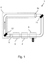
- FIG. 1 schematically shows a plant 1 for the production of cosmetic products in which different process steps in the areas 2, 3, 4 are performed.
- the areas 2, 3, 4 are arranged consecutively.
- Appendix 1 for example, lipstick mines are produced.
- two molds 11, 12 are heated in the area 2, and then in the area 3 a heated pasty mass, for example consisting of waxes and additives, is filled into the molds 11, 12.
- a heated pasty mass for example consisting of waxes and additives
- the area 4 can also be referred to as a cooling section.
- the casting molds 11, 12 pass through the individual regions during the production process, the casting molds being held by mold carriers, for example, and the mold carriers being moved on a transport system which moves the casting molds 11, 12 through the individual regions 2, 3, 4.
- the mold carriers can move independently of each other.
- the first casting mold 11 has already passed through the region 4, that is to say the cooling stretch, whereas the second casting mold 12 is still at the beginning of the region 4.
- a mold carrier may also hold multiple molds, in which case a first mold is one of the molds held by a first mold carrier and a second mold is a mold of multiple molds held by a second mold carrier.
- the system 1 further comprises two sensors 5, 5c, with the aid of which process parameters, here the temperature of the casting molds 11, 12 or the pasty mass in the casting molds 11, 12, are detected at the sensor location.
- process parameters here the temperature of the casting molds 11, 12 or the pasty mass in the casting molds 11, 12, are detected at the sensor location.
- the temperature of the casting molds 11, 12 is detected.
- the sensor 5 is located in front of the cooling section 4 and the sensor 5c at the end of the cooling section 4.
- the temperatures detected by the sensors 5, 5c represent actual values and are compared with predetermined desired values, which are predetermined by an operator, for example. According to the deviation of the actual value from the target value, the cycle time of the molds 11, 12 and the cooling capacity of the cooling section 4 are controlled.
- the actual temperature of the first mold 11 was detected before the cooling section 4 with the sensor 5 and the actual temperature of the first mold 11 after the cooling section 4 with the sensor 5c.
- the cycle time of the second mold 12 is controlled by the cooling section 4 and the cooling capacity of the cooling section 4.
- the passage time and / or the cooling capacity is controlled such that the difference between the actual temperature and the target temperature turns out to be as small as possible. This control can be performed even more differentiated, if it is known which actual temperature had the first mold 11 in front of the cooling section 4 and which actual temperature has the second mold 12 in front of the cooling section 4.
- the second casting mold 12 When the second casting mold 12 has passed through the cooling section 4, its actual temperature is detected by sensor 5c. This detected actual temperature and its deviation from the target temperature is then used to control the cycle time of a mold following the second mold - not shown here - to control and / or the cooling capacity of the cooling section 4 for the corresponding mold.
- an iterative control is provided, which independently regulates the cycle time and the cooling capacity, to achieve an optimal cooling process, the operator only having to specify the target value (s), but without otherwise having to intervene.
- the predetermined desired value can also be predetermined by a superordinate control, but whose programming has been carried out by an operator, so that the setpoint value is predetermined at least indirectly by an operator.
- the casting molds 11, 12 can be carried, for example, by mold carriers (not shown here), wherein a mold carrier can carry at least one casting mold.
- a mold carrier can carry at least one casting mold.
- the casting molds 11, 12 can be removed from the plant 1 or other casting molds - not shown here - can be added to the plant 1.
- the number of mold carriers located in the system 1 and thus the number of molds located in the system 1 can be adjusted. This can happen, for example, in a change area 6 of Appendix 1.
- FIG. 2 shows again in the FIG. 1 shown Appendix 1 for the manufacture of cosmetic products, but with a subdivision of the cooling section 4 in three areas 4a, 4b, 4c.
- Each of the areas 4a, 4b, 4c of the cooling section 4 has an associated temperature sensor 5a, 5b, 5c, with which the temperature of the molds at the end of each of the areas 4a, 4b, 4c of the cooling section 4 can be detected.
- the plurality of temperature sensors 5a, 5b, 5c make it possible to iteratively control the throughput times and cooling capacities in the individual regions 4a, 4b, 4c of the cooling section 4 in accordance with an actual nominal value comparison for the continuous casting molds, wherein the casting molds or the mold carriers individually, ie independently of each other, through the plant 1 can move.
- the individual mold carriers or casting molds can have different throughput times, which is indicated by their different distances in the exemplary embodiment shown here.
- the casting molds can first be collected and in a certain timing, for example every 3 seconds, in the area 2 be fed so that at least in the areas 2 and 3, a constant timing can be guaranteed.
Description
Die vorliegende Erfindung betrifft im Allgemeinen das Steuern eines Abkühlprozesses von Gießformen. Die vorliegende Erfindung betrifft insbesondere das selbsttätige Steuern eines Abkühlprozesses von Gießformen bei der Herstellung kosmetischer Produkte, basierend auf zumindest einem erfassten Prozessparameter in einer Anlage.The present invention generally relates to controlling a cooling process of molds. In particular, the present invention relates to the automatic control of a cooling process of casting molds in the manufacture of cosmetic products, based on at least one detected process parameter in a plant.
Kosmetische Produkte, wie zum Beispiel Lippenstifte beziehungswiese Lippenstiftminen, werden heutzutage in fast vollständig automatisierten Anlagen hergestellt. In diesen Anlagen finden mehrere Prozessschritte des Herstellungsverfahrens nacheinander statt und die kosmetischen Produkte werden durch diese Prozessschritte geführt oder geleitet, wobei am Ende der Anlage das fertige kosmetische Produkt entnommen wird. Wenn es sich bei dem kosmetischen Produkt beispielswiese um Lippenstiftminen handelt, so werden diese in mehreren Prozessschritten hergestellt. Als erstes wird ein Gemisch unterschiedlicher Wachse und Additive hergestellt, welches das Grundmaterial der Lippenstiftminen darstellt. Dieses Grundmaterial wird erhitzt, um in einen fließfähigen Zustand überführt zu werden. In einem nächsten Prozessschritt wird das fließfähige Grundmaterial in eine Gießform gefüllt. Die Gießform kann dabei eine Produktionskomponente in der Anlage darstellen. Die Gießform wird anschließend abgekühlt, damit das Grundmaterial in der Gießform zumindest teilweise erstarren kann, um die Gestalt der Gießform dauerhaft anzunehmen. Das Erhitzen des Gemisches der unterschiedlichen Wachse und Additive, das Befüllen der Gießformen mit dem fließfähigen Grundmaterial sowie das anschließende Abkühlen der Gießformen stellen die drei Haupt-Prozessschritte bei der Herstellung von Lippenstiftminen dar, die in der Anlage ausgeführt werden. Es können aber auch noch weitere Prozessschritte neben diesen Haupt-Prozessschritten ausgeführt werden. Die Produktionsleistung der Anlage, d.h. die ausgegebene Stückzahl pro Zeiteinheit, ist direkt abhängig von den Zeiten, die die einzelnen Prozessschritte in Anspruch nehmen. Der Abkühlprozess nimmt dabei im Vergleich zu den beiden anderen Haupt-Prozessschritten in der Regel die längste Zeit in Anspruch. Das Abkühlen geschieht dabei zumeist in einer Kühlstrecke. Die Kühlstrecke stellt einen Bereich oder eine Zone der Anlage dar, in der das Temperaturniveau der Gießformen herabgesetzt wird. Dabei hat die Kühlstrecke zumeist eine gewisse räumliche Ausdehnung und die Gießformen werden durch die Kühlstrecke bewegt oder bewegen sich selbstständig hindurch. Innerhalb der Kühlstrecke herrscht dabei ein zumeist regelbares Temperaturniveau, welches unterhalb des Temperaturniveaus liegt, das die Gießformen nach dem Befüllen haben. In der Kühlstrecke wird den Gießformen somit Entropie entzogen, die Gießformen werden also abgekühlt.Cosmetic products, such as lipsticks or lipstick leads, are now manufactured in almost completely automated facilities. In these plants, several process steps of the manufacturing process take place in succession and the cosmetic products are passed or passed through these process steps, the finished cosmetic product being taken at the end of the plant. If the cosmetic product is, for example, lipstick leads, these are produced in several process steps. First, a mixture of different waxes and additives is prepared, which is the base material of the lipstick mines. This base material is heated to be transferred to a flowable state. In a next process step, the flowable base material is filled into a casting mold. The mold can represent a production component in the system. The mold is then cooled so that the base material in the mold can at least partially solidify to permanently assume the shape of the mold. The heating of the mixture of the different waxes and additives, the filling of the casting molds with the flowable base material and the subsequent cooling of the casting molds represent the three main process steps in the production of lipstick leads, which are carried out in the plant. However, it is also possible to carry out further process steps besides these main process steps. The production output of the plant, ie the output Number of pieces per time unit, is directly dependent on the times taken by the individual process steps. The cooling process usually takes the longest time compared to the other two main process steps. The cooling is usually done in a cooling section. The cooling section represents an area or zone of the plant in which the temperature level of the molds is reduced. The cooling section usually has a certain spatial extent and the casting molds are moved through the cooling section or move independently through it. Within the cooling section, a mostly controllable temperature level prevails, which is below the temperature level that the casting molds have after filling. Entropy is thus removed from the casting molds in the cooling section, ie the casting molds are cooled.
Bei der Verfolgung des Zieles, die Produktionsleistung der Anlage zu optimieren, müssen also die für die Prozessschritte nötigen Zeiten herabgesetzt werden. Dies ist aber gerade in Bezug auf den Abkühlprozess nicht ohne Weiteres möglich, da die Gießformen nicht beliebig schnell abgekühlt werden können, sondern ein definiertes Kühlverhalten eingehalten werden muss, damit die Wachse und Additive nicht unkontrolliert erstarren, wodurch sich Beschädigungen an der Oberfläche ergeben könnten, die den Gesamteindruck der Lippenstiftmine schmälern würden und diese nicht mehr hochwertig erscheinen ließen. Es ist daher nötig den Abkühlprozess derart einzustellen, dass dieser die kürzest mögliche Zeit in Anspruch nimmt, aber dem Kühlverhalten der Wachse und Additive Rechnung trägt, so dass am Ende des Abkühlprozesses ein hochwertiges Produkt vorliegt.In pursuing the goal of optimizing the production output of the plant, therefore, the times required for the process steps must be reduced. However, this is not readily possible with regard to the cooling process, since the casting molds can not be cooled arbitrarily fast, but a defined cooling behavior must be maintained, so that the waxes and additives do not solidify uncontrollably, which could result in damage to the surface, which would diminish the overall impression of the lipstick mine and make them no longer appear high-quality. It is therefore necessary to adjust the cooling process so that it takes the shortest possible time, but the cooling behavior of the waxes and additives into account, so that at the end of the cooling process, a high quality product is present.
Es sind Verfahren und Vorrichtungen bekannt, mit deren Hilfe versucht wird, die Produktionsleistung von Anlagen für die Herstellung von Lippenstiftminen zu erhöhen. Hierbei weisen die Anlagen für Lippenstiftminen beispielsweise einen sogenannten fließenden Produktionsprozess auf, der durch einen stetigen Vorschub von Produktionskomponenten in Form einer Rundtaktung der verschiedenen Prozessschritte in der Anlage gekennzeichnet ist. Mit Hilfe des Prinzips der unmittelbar nacheinander angeordneten Prozessschritte bei der Rundtaktung kann die Produktion beschleunigt werden, da in der Anlage beispielsweise der Anteil der Transferzeit zwischen den Prozessschritten an der gesamten Produktionszeit verringert werden kann.Methods and devices are known that attempt to increase the production output of lipstick mine production equipment. Here, the facilities for lipstick mines, for example, a so-called fluid production process, which is characterized by a steady feed of production components in the form of a rotary indexing of the various process steps in the system. With the help of the principle of immediately successively arranged process steps in the rotary indexing the production can be accelerated because in the plant For example, the proportion of transfer time between the process steps in the entire production time can be reduced.
In der
Es stellt sich daher die Aufgabe, ein Verfahren und eine Vorrichtung bereitzustellen, die den oben genannten Nachteil nicht aufweist. Insbesondere soll mit dem Verfahren und der Vorrichtung die funktionale Abhängigkeit zwischen der Dauer des Abkühlprozesses und der Taktzeit der anderen Prozessschritte in der Anlage aufgelöst werden.It is therefore the object to provide a method and a device which does not have the above-mentioned disadvantage. In particular, with the method and the device, the functional dependence between the duration of the cooling process and the cycle time of the other process steps in the system should be resolved.
Diese Aufgabe wird mit dem Verfahren und der Vorrichtung der unabhängigen Ansprüche gelöst. Vorteilhafte Ausführungsformen sind in den Unteransprüchen beschrieben.This object is achieved by the method and the device of the independent claims. Advantageous embodiments are described in the subclaims.
Das erfindungsgemäße Verfahren zum Steuern eines Abkühlprozesses von Gießformen für kosmetische Produkte beim Durchlaufen einer Kühlstrecke in einer Anlage in einem zyklischen Regelkreislauf weist das Erfassen zumindest eines ersten Prozessparameters auf, zugehörig zu einer ersten Gießform. Darüber hinaus weist das Verfahren auf das Steuern einer Durchlaufzeit einer zweiten Gießform durch die Kühlstrecke, basierend auf dem zumindest einen ersten Prozessparameter, sowie das Steuern eines Kühlverhaltens der Kühlstrecke beim Durchlaufen der zweiten Gießform, basierend auf dem zumindest einen ersten Prozessparameter. Die erste Gießform, die die Kühlstrecke durchläuft, erfüllt dabei quasi eine Testfunktion. Beispielsweise kann mit dem Durchlaufen der ersten Gießform und mit dem Erfassen des zumindest einen ersten Prozessparameters die Kühlstrecke in der Anlage initialisiert werden. In der Initialisierungsphase kann beispielsweise nur die erste Gießform die Kühlstrecke durchlaufen und die zweite Gießform kann erst nach vollständigem Durchlaufen der ersten Gießform durch die Kühlstrecke der Kühlstrecke zugeführt werden. Dabei kann dann die Durchlaufzeit der zweiten Gießform und das Kühlverhalten der Kühlstrecke beim Durchlaufen der zweiten Gießform angepasst werden, basierend auf dem ersten Prozessparameter, der für die erste Gießform erfasst wurde. Beispielsweise kann aber auch bereits die zweite Gießform der Kühlstrecke zugeführt werden, bevor die erste Gießform die Kühlstrecke vollständig durchlaufen hat. In diesem Fall kann die erste Gießform auch als primäre Gießform bezeichnet werden und die zweite Gießform kann als sekundäre Gießform bezeichnet werden. Hierbei gilt, dass die sekundäre Gießform für eine weitere Gießform, die ihr bei dem Durchlaufen durch die Kühlstrecke nachfolgt, wiederum die Funktion einer primären Gießform einnimmt, so dass sich ein zyklischer Regelkreislauf ergibt. Das bedeutet, dass die Durchlaufzeit einer nachfolgenden Gießform und das Kühlverhalten der Kühlstrecke für die nachfolgende Gießform gesteuert werden, basierend auf zumindest dem ersten Prozessparameter, erfasst für die vorhergehende Gießform. Der Regelkreislauf kann dabei direkt sein, d.h. eine Regelung kann ausgehend von einer ersten Gießform für die direkt nachfolgende zweite Gießform stattfinden. Der Regelkreislauf kann aber auch indirekt sein, d.h. eine Regelung kann ausgehend von einer ersten Gießform für eine nachfolgende zweite Gießform stattfinden, wobei die zweite Gießform der ersten Gießform nicht direkt nachfolgt. Das bedeutet, dass zwischen der ersten Gießform und der zweiten Gießform auch weitere Gießformen die Kühlstrecke durchlaufen können. Es ist dem Fachmann bewusst, dass, auch wenn hier nur einzelne Verfahrensschritte des erfindungsgemäßen Verfahrens genannt sind, diese Verfahrensschritte iterativ ausgeführt werden und so eine ständige Regelung des Abkühlprozesses stattfindet. Es reicht dabei aus einen Prozessparameter zu erfassen, weil dieser einen gewünschten Zustand der Gießformen darstellt, dessen Erreichen das Ziel der Steuerung ist.The inventive method for controlling a cooling process of molds for cosmetic products when passing through a cooling section in a system in a cyclic control circuit comprises detecting at least a first process parameter, associated with a first mold. In addition, the method comprises controlling a passage time of a second casting mold through the cooling section, based on the at least one first process parameter, and controlling a cooling behavior of the cooling section when passing through the second mold, based on the at least one first process parameter. The first mold, which passes through the cooling section, thereby fulfills a quasi-test function. For example, with the passage of the first mold and with the detection of the at least one first process parameter, the cooling section in the system can be initialized. In the initialization phase, for example, only the first casting mold can pass through the cooling section and the second casting mold can be fed through the cooling section of the cooling section only after complete passage through the first casting mold. In this case, the throughput time of the second casting mold and the cooling behavior of the cooling section during passage through the second casting mold can then be adapted, based on the first process parameter that was detected for the first casting mold. For example, but already the second mold of the cooling section can be supplied before the first mold has completely passed through the cooling section. In this case, the first mold may also be referred to as a primary mold and the second mold may be referred to as a secondary mold. In this case, the secondary casting mold for another casting mold, which follows it when passing through the cooling section, again assumes the function of a primary casting mold, resulting in a cyclical control loop. That is, the passage time of a succeeding mold and the cooling behavior of the cooling path for the succeeding mold are controlled based on at least the first process parameter detected for the preceding mold. The control circuit can be direct, ie a regulation can take place starting from a first mold for the directly following second mold. However, the control loop can also be indirect, ie a regulation can take place starting from a first casting mold for a subsequent second casting mold, the second casting mold not directly following the first casting mold. This means that between the first mold and the second mold and other molds can pass through the cooling section. It is known to the person skilled in the art that, even if only individual method steps of the method according to the invention are mentioned here, these method steps are carried out iteratively and thus a continuous regulation of the cooling process takes place. It is sufficient to record a process parameter because of this represents a desired state of the molds, the achievement of which is the goal of the control.
Der Abkühlprozess kann gesteuert beziehungsweise geregelt werden, indem die Durchlaufzeit der Gießformen durch die Kühlstrecke gesteuert wird, wobei die Durchlaufzeit der Gießformen für jede Gießform individuell variiert werden kann. Das bedeutet, dass die Verweildauer jeder Gießform in der Kühlstrecke individuell eingestellt werden kann. Dabei ist der Vorschub der Gießformen durch die Kühlstrecke auch entkoppelt von dem Vorschub, den die Gießformen in den anderen Prozessschritten erfahren. Es kann auch gesagt werden, dass die Taktzeiten der Gießformen in den unterschiedlichen Prozessschritten unabhängig voneinander sind. Zur Steuerung der Durchlaufzeit wird die Durchlaufzeit einer ersten Gießform, bei der es sich beispielsweise um eine primäre Gießform handeln kann, durch die Kühlstrecke dem zumindest einen erfassten ersten Prozessparameter gegenübergestellt, und es kann die Differenz zwischen einem Ist-Wert und einem Soll-Wert des zumindest einen Prozessparameters bestimmt werden. Wenn die Differenz zwischen dem Ist-Wert und dem Soll-Wert des zumindest einen ersten Prozessparameters bei dem Durchlaufen der primären Gießform durch die Kühlstrecke einen Grenzwert überschreitet, kann die Durchlaufzeit der sekundären Gießform durch die Kühlstrecke angepasst werden, so dass die Differenz zwischen dem Ist-Wert und dem Soll-Wert des zumindest einen ersten Prozessparameters, erfasst für die sekundäre Gießform, die eine primäre Gießform für eine nachfolgende Gießform ist, geringer wird, bis die Differenz gleich oder kleiner ist als der Grenzwert.The cooling process can be controlled by controlling the flow time of the molds through the cooling path, whereby the flow time of the molds for each mold can be varied individually. This means that the dwell time of each mold in the cooling section can be set individually. The feed of the casting molds through the cooling section is also decoupled from the feed that the casting molds experience in the other process steps. It can also be said that the cycle times of the molds in the different process steps are independent of each other. In order to control the cycle time, the cycle time of a first casting mold, which may be, for example, a primary casting mold, is compared with the at least one detected first process parameter by the cooling stretch, and the difference between an actual value and a target value of the at least one process parameter can be determined. If the difference between the actual value and the target value of the at least one first process parameter when passing through the primary mold through the cooling section exceeds a limit, the cycle time of the secondary mold can be adjusted by the cooling section, so that the difference between the actual Value and the target value of the at least one first process parameter detected decreases for the secondary casting mold, which is a primary casting mold for a subsequent casting mold, until the difference is equal to or less than the limit value.
Der Abkühlprozess kann auch gesteuert werden, indem das Kühlverhalten der Kühlstrecke gesteuert wird. Dabei wird zunächst das Kühlverhalten der Kühlstrecke bei dem Durchlaufen der ersten Gießform, bei der es sich beispielsweise um eine primäre Gießform handeln kann, dem zumindest einen erfassten ersten Prozessparameter gegenübergestellt und somit kann die Differenz zwischen einem Ist-Wert und einem Soll-Wert des zumindest einen Prozessparameters erfasst werden. Wenn die Differenz zwischen dem Ist-Wert und dem Soll-Wert des zumindest einen ersten Prozessparameters bei dem Durchlaufen der primären Gießform durch die Kühlstrecke, also beispielsweise das von der Kühlstrecke zur Verfügung gestellte Temperaturniveau, einen Grenzwert überschreitet, kann das Kühlverhalten der Kühlstrecke bei dem Durchlaufen der sekundären Gießform durch die Kühlstrecke so angepasst werden, dass die Differenz zwischen dem Ist-Wert und dem Soll-Wert des zumindest einen Prozessparameters, erfasst für die sekundäre Gießform, die eine primäre Gießform für eine nachfolgende Gießform ist, geringer wird, bis die Differenz gleich oder kleiner ist als der Grenzwert.The cooling process can also be controlled by controlling the cooling behavior of the cooling section. In this case, first the cooling behavior of the cooling section when passing through the first casting mold, which may be, for example, a primary casting mold, is compared with the at least one detected first process parameter and thus the difference between an actual value and a target value of at least a process parameter is detected. When the difference between the actual value and the target value of the at least one first process parameter in the Passing through the primary mold through the cooling section, so for example, the temperature level provided by the cooling section, exceeds a limit, the cooling behavior of the cooling section can be adjusted by passing the secondary mold through the cooling section so that the difference between the actual value and the target value of the at least one process parameter detected for the secondary mold, which is a primary mold for a subsequent mold, becomes smaller until the difference is equal to or smaller than the threshold value.
Das Steuern der Durchlaufzeit kann von dem Steuern des Kühlverhaltens unabhängig sein. Das bedeutet, dass nicht in jedem Iterationsschritt jeweils beide, die Durchlaufzeit und das Kühlverhalten, gesteuert werden müssen. Beispielsweise kann eine Steuergröße konstant gehalten werden und die andere Steuergröße geändert werden. Auch das Konstanthalten zumindest einer Steuergröße fällt unter den Begriff des Steuerns.Controlling the cycle time may be independent of controlling the cooling behavior. This means that it is not necessary to control both the throughput time and the cooling behavior in each iteration step. For example, one control variable can be kept constant and the other control variable can be changed. Also keeping constant at least one control variable falls under the concept of controlling.
Die Kühlstrecke sorgt dabei dafür, dass die Entropie der Gießformen herabgesetzt wird. Mit der Steuerung der Durchlaufzeit und des Kühlverhaltens der Kühlstrecke, lässt sich somit das Entropieverhalten der Gießformen bestimmen. Das Abkühlverhalten der Gießformen kann also vorgegeben werden. Dieses Verhalten lässt sich dementsprechend über die Vorgabe eines Soll-Wertes für den ersten Prozessparameter regeln. Dabei ist das Abkühlverhalten auch unabhängig von den Taktzeiten der anderen Prozesse in der Anlage.The cooling section ensures that the entropy of the casting molds is reduced. With the control of the flow time and the cooling behavior of the cooling section, thus the entropy behavior of the casting molds can be determined. The cooling behavior of the molds can therefore be specified. This behavior can accordingly be regulated by specifying a desired value for the first process parameter. The cooling behavior is also independent of the cycle times of the other processes in the plant.
In einer bevorzugten Ausführungsform des erfindungsgemäßen Verfahrens weist dieses weiter auf das Erfassen zumindest eines zweiten Prozessparameters, zugehörig zu der ersten Gießform. Der zumindest eine zweite Prozessparameter kann sich dabei vom ersten Prozessparameter dadurch unterscheiden, dass dieser in einem anderen Bereich in der Anlage erfasst wird, als der erste Prozessparameter. Die Prozessparameter können sich aber alternativ oder zusätzlich auch dadurch unterscheiden, dass eine andere Messgröße erfasst wird. Beispielsweise können mehrere zweite Prozessparameter erfasst werden. Das Steuern der Durchlaufzeit und / oder das Steuern des Kühlverhaltens kann dann zusätzlich auch auf dem zumindest einen zweiten erfassten Prozessparameter beruhen, um eine differenziertere Steuerung zu erlauben.In a preferred embodiment of the method according to the invention, this further points to the detection of at least one second process parameter associated with the first casting mold. The at least one second process parameter may differ from the first process parameter in that it is detected in a different area in the plant than the first process parameter. However, the process parameters may alternatively or additionally also differ in that a different measured variable is detected. For example, several second Process parameters are detected. The controlling of the cycle time and / or the controlling of the cooling behavior can then additionally be based on the at least one second detected process parameter, in order to allow a more differentiated control.
Der erste und der zumindest eine zweite Prozessparameter können beispielsweise die Temperatur der Gießform in unterschiedlichen Bereichen der Anlage darstellen. Der erste Prozessparameter kann dabei beispielsweise eine erste Temperatur der ersten Gießform vor oder nach der Kühlstrecke darstellen und entsprechend der erfassten ersten Temperatur kann die Durchlaufzeit der zweiten Gießform durch die Kühlstrecke gesteuert werden und das Kühlverhalten der Kühlstrecke kann gesteuert werden. Beispielsweise kann der erste Prozessparameter die erste Temperatur der ersten Gießform am Anfang der Kühlstrecke oder am Ende der Kühlstrecke darstellen.The first and the at least one second process parameters may, for example, represent the temperature of the casting mold in different areas of the plant. The first process parameter can represent, for example, a first temperature of the first mold before or after the cooling section and according to the detected first temperature, the cycle time of the second mold can be controlled by the cooling section and the cooling behavior of the cooling section can be controlled. For example, the first process parameter may represent the first temperature of the first mold at the beginning of the cooling section or at the end of the cooling section.
Während des Durchlaufens der Kühlstrecke wird die erste Gießform von einem hohen Temperaturniveau auf ein niedriges Temperaturniveau gekühlt und das Abkühlen kann mittels der erfassten ersten Temperatur überwacht werden. Die erfasste erste Temperatur stellt dabei einen Ist-Wert dar und kann mit einem Soll-Wert verglichen werden, der beispielsweise von einem Bediener vorgegebenen werden kann. Anhand der Differenz zwischen dem Ist-Wert und dem Soll-Wert kann überwacht werden, in wie weit der Abkühlprozess und die damit zu erreichende Absenkung des Temperaturniveaus von der ersten Gießform den Vorgaben entsprechen. Der zumindest eine Soll-Wert, der von dem Bediener vorgegeben werden kann, kann auch einen Grenzwert darstellen und bei dem Durchlaufen der ersten Gießform durch die Kühlstrecke kann ein Über- oder ein Unterschreiten des zumindest einen Grenzwertes geprüft werden. Basierend auf dem Über- oder Unterschreiten des zumindest einen Grenzwertes, kann beispielsweise das Durchlaufen der zweiten Gießform durch die Kühlstrecke gesteuert werden sowie das Kühlverhalten der Kühlstrecke selbst, indem beispielsweise das Temperaturniveau der Kühlstrecke, das auf die zweite Gießform einwirkt und dadurch der zweiten Gießform Entropie entzieht, variiert wird. Dabei wird der Abkühlprozess bei dem Durchlaufen der zweiten Gießform durch die Kühlstrecke so angepasst, dass den Vorgaben bezüglich der zu erreichenden Absenkung des Temperaturniveaus der zweiten Gießform besser entsprochen werden kann, als dies bei dem Durchlaufen der ersten Gießform durch die Kühlstrecke der Fall war. Die zu erreichende Absenkung des Temperaturniveaus kann beispielsweise eine Temperaturdifferenz von 60 Kelvin aufweisen. Bei dem Durchlaufen der zweiten Gießform durch die Kühlstrecke kann die Durchlaufzeit der zweiten Gießform beispielsweise verkürzt oder verlängert werden, so dass die zweite Gießform entweder länger oder kürzer in der Kühlstrecke verbleibt, so dass der zweiten Gießform mehr oder weniger Entropie entzogen wird.During the passage of the cooling section, the first mold is cooled from a high temperature level to a low temperature level, and the cooling can be monitored by means of the detected first temperature. The detected first temperature represents an actual value and can be compared with a desired value, which can be predetermined by an operator, for example. Based on the difference between the actual value and the target value, it can be monitored to what extent the cooling process and the reduction of the temperature level from the first casting mold to be achieved correspond to the specifications. The at least one desired value, which can be predetermined by the operator, can also represent a limit value and, when passing through the first casting mold through the cooling section, an overshoot or undershoot of the at least one limit value can be checked. Based on the exceeding or falling below the at least one limit value, for example, the passage through the second casting mold can be controlled by the cooling section and the cooling behavior of the cooling section itself, for example, the temperature level of the cooling section, which acts on the second mold and thereby the second mold entropy withdraws, is varied. In this case, the cooling process in the passage through the second mold by the Cooling section adapted so that the specifications regarding the achievable lowering of the temperature level of the second mold can be better met, as was the case when passing through the first mold through the cooling section. The achievable lowering of the temperature level may, for example, have a temperature difference of 60 Kelvin. When passing through the second casting mold through the cooling section, the cycle time of the second casting mold can be shortened or lengthened, for example, so that the second casting mold either remains longer or shorter in the cooling zone, so that more or less entropy is removed from the second casting mold.
Das Steuern des Kühlverhaltens der Kühlstrecke beim Durchlaufen der zweiten Gießform kann das Reduzieren oder Erhöhen der Kühlleistung der Kühlstrecke in zumindest einem Bereich der Kühlstrecke umfassen. Die Kühlleistung kann also in einem Bereich der Kühlstrecke anders sein, als in dem zumindest einen weiteren Bereich der Kühlstrecke. Das bedeutet, dass die Kühlstrecke in unterschiedlichen Bereichen unterschiedliche Temperaturniveaus aufweisen kann.Controlling the cooling behavior of the cooling section when passing through the second casting mold may include reducing or increasing the cooling capacity of the cooling section in at least one region of the cooling section. The cooling capacity may thus be different in one area of the cooling section than in the at least one further area of the cooling section. This means that the cooling section can have different temperature levels in different areas.
Beispielsweise kann bei dem Durchlaufen der ersten Gießform die Temperatur der ersten Gießform vor der Kühlstrecke und die Temperatur der ersten Gießform am Ende eines ersten Bereiches der Kühlstrecke erfasst werden. Die erfasste Temperatur am Ende des ersten Bereiches der Kühlstrecke kann mit einem Soll-Wert verglichen werden, der einen ersten Grenzwert darstellen kann. Wird bei dem Durchlaufen der ersten Gießform durch den ersten Bereich der Kühlstrecke der erste Grenzwert überschritten, bedeutet das, dass die erste Gießform am Ende des ersten Bereiches der Kühlstrecke ein zu hohes Temperaturniveau aufweist. Um das Temperaturniveau der ersten Gießform am Ende der Kühlstrecke besser an das vorgegebene Temperaturniveau anpassen zu können und somit auf das vorgegebene Temperaturniveau am Ende der Kühlstrecke abzusenken, kann die Kühlleistung in dem zumindest einen weiteren Bereich der Kühlstrecke erhöht werden. Umgekehrt kann die Kühlleistung in dem zumindest einen weiteren Bereich der Kühlstrecke reduziert werden, wenn bei dem Durchlaufen der ersten Gießform durch den ersten Bereich der Kühlstrecke der erste Grenzwert unterschritten wurde. Für die zweite Gießform kann die Kühlleistung im ersten Bereich der Kühlstrecke erhöht werden, wenn die erfasste Temperatur der ersten Gießform gezeigt hat, dass das Temperaturniveau der ersten Gießform zu hoch war. Umgekehrt kann die Kühlleistung für die zweite Gießform reduziert werden, wenn das Temperaturniveau der ersten Gießform zu niedrig war. Beispielsweise kann die Kühlleistung auch in beiden Bereichen, aus der erfassten Temperatur am Ende des zumindest einen Bereiches, gemittelt werden.For example, when passing through the first mold, the temperature of the first mold upstream of the cooling section and the temperature of the first mold at the end of a first region of the cooling section can be detected. The detected temperature at the end of the first region of the cooling section can be compared with a desired value, which can represent a first limit value. If, during the passage through the first casting mold through the first region of the cooling path, the first limit value is exceeded, this means that the first casting mold has an excessively high temperature level at the end of the first region of the cooling stretch. In order to better adapt the temperature level of the first mold at the end of the cooling section to the predetermined temperature level and thus to lower to the predetermined temperature level at the end of the cooling section, the cooling capacity can be increased in the at least one further region of the cooling section. Conversely, the cooling capacity in the at least one further region of the cooling section can be reduced if, when passing through the first casting mold through the first range of the cooling section, the first limit was exceeded. For the second mold, the cooling performance in the first region of the cooling path can be increased if the detected temperature of the first mold has shown that the temperature level of the first mold was too high. Conversely, the cooling performance for the second mold can be reduced if the temperature level of the first mold was too low. For example, the cooling capacity can also be averaged in both areas, from the detected temperature at the end of the at least one area.
In einer weiteren bevorzugten Ausführungsform des erfindungsgemäßen Verfahrens weist das Verfahren auf das Anpassen einer Anzahl der in der Anlage vorhandenen Gießformen, wobei die Anzahl der in der Anlage vorhandenen Gießformen auf dem ersten Prozessparameter und / oder dem zumindest einen zweiten Prozessparameter basiert. Um bei dem Durchlaufen der Gießformen durch die Kühlstrecke die vorgegebene Temperatur der Gießformen am Ende der Kühlstrecke zu erreichen, kann jede Gießform oder eine Gruppe von Gießformen mit einer individuellen Geschwindigkeit durch die Kühlstrecke bewegt werden, wobei sich die Geschwindigkeit bei dem Durchlaufen durch die Kühlstrecke von der Geschwindigkeit bei dem Durchlaufen der anderen Prozessschritte in der Anlage unterscheiden kann. Man kann also auch sagen, dass bei dem Durchlaufen der Gießformen durch die Kühlstrecke keine funktionale Abhängigkeit zwischen der Dauer des Abkühlprozesses und der Taktzeit der anderen Prozessschritte in der Anlage besteht. Durch die individuelle Geschwindigkeit, mit der jede Gießform oder die Gruppe von Gießformen durch die Kühlstrecke bewegt werden kann, und dadurch, dass sich die Geschwindigkeit der Gießformen bei dem Durchlaufen durch die Kühlstrecke von der Geschwindigkeit bei dem Durchlaufen der anderen Prozessschritte in der Anlage unterscheiden kann, kann bei dem Durchlaufen der Kühlstrecke der Abstand zwischen den Gießformen variieren. Wird beispielsweise die Geschwindigkeit einer Gießform bei dem Durchlaufen durch die Kühlstrecke erhöht, vergrößert sich der Abstand zwischen ihr und einer ihr nachfolgenden Gießform.In a further preferred embodiment of the method according to the invention, the method comprises adapting a number of the casting molds present in the installation, wherein the number of casting molds present in the installation is based on the first process parameter and / or the at least one second process parameter. In order to achieve the predetermined temperature of the casting molds at the end of the cooling section when passing through the casting molds through the cooling section, each mold or a group of molds can be moved through the cooling section at an individual speed, wherein the speed when passing through the cooling section of can distinguish the speed when going through the other process steps in the plant. It can therefore also be said that there is no functional dependency between the duration of the cooling process and the cycle time of the other process steps in the plant when passing through the casting molds through the cooling section. By the individual speed with which each mold or group of molds can be moved through the cooling section and in that the speed of the molds as they pass through the cooling section may differ from the speed in passing through the other process steps in the system , the distance between the molds may vary when passing through the cooling section. If, for example, the speed of a casting mold increases as it passes through the cooling section, the distance between it and a casting mold following it increases.
Dadurch, dass sich der Abstand zwischen den Gießformen bei dem Durchlaufen durch die Kühlstrecke erhöhen kann, können sich Lücken bilden, die groß genug sein können, um genug Platz für zumindest eine weitere Gießform zu bieten. Die Steuerung des Abkühlprozesses in der Anlage kann die Bildung von Lücken erkennen, die groß genug sind, um genug Platz für zumindest eine weitere Gießform zu bieten. Dadurch, dass sich Lücken bilden, kann die Anzahl der am Abkühlprozess beteiligten Gießformen - also die Anzahl der Gießformen, die sich gleichzeitig in der Kühlstrecke befinden - erhöht werden, indem beispielsweise die Anzahl der Gießformen erhöht wird, die der Kühlstrecke pro Zeiteinheit zugeführt werden. Dies kann beispielsweise dadurch initiiert werden, indem die Geschwindigkeit erhöht wird, mit der die Gießformen in die Kühlstrecke zugeführt werden. Es wird jedoch deutlich, dass die Anzahl der Gießformen, die am Abkühlprozess beteiligt sind, nicht beliebig erhöht werden kann. Eine Obergrenze ist beispielsweise dann erreicht, wenn die Maximalbelegung der Kühlstrecke erreicht ist.The fact that the distance between the molds can increase when passing through the cooling section, gaps can form, which can be large enough to provide enough space for at least one other mold. Control of the cooling process in the plant can detect the formation of voids large enough to provide enough space for at least one other mold. The fact that gaps form, the number of casting molds involved in the cooling process - ie the number of molds that are located simultaneously in the cooling section - can be increased by, for example, the number of molds is increased, which are supplied to the cooling section per unit time. This can be initiated, for example, by increasing the speed at which the casting molds are fed into the cooling section. However, it is clear that the number of molds involved in the cooling process can not be arbitrarily increased. An upper limit is reached, for example, when the maximum occupancy of the cooling section has been reached.
Die Anzahl der am Abkühlprozess beteiligten Gießformen kann beispielsweise aber auch dann nicht weiter erhöht werden, wenn vor der Kühlstrecke keine weiteren Gießformen für das Zuführen in die Kühlstrecke zur Verfügung stehen. Das kann beispielsweise dann der Fall sein, wenn die Anzahl der Gießformen, die pro Zeiteinheit aus dem Prozessschritt vor der Kühlstrecke hervorgehen, nicht weiter erhöht werden kann.However, the number of casting molds involved in the cooling process can not be increased further, for example, even if no further casting molds for feeding into the cooling zone are available in front of the cooling section. This may be the case, for example, if the number of casting molds that emerge from the process step upstream of the cooling section per unit of time can not be increased any further.
Für den Fall, dass die Maximalbelegung der Kühlstrecke noch nicht erreicht ist, gleichzeitig jedoch vor der Kühlstrecke keine weiteren Gießformen zur Verfügung stehen, kann das Verfahren das Hinzufügen von zumindest einer Gießform in die Anlage und somit das Erhöhen der Anzahl der in der Anlage vorhandenen Gießformen aufweisen. Die Anzahl der in der Anlage vorhandenen Gießformen kann beispielsweise erhöht werden, wenn die Steuerung des Abkühlprozesses in der Anlage erkennt, dass die Kühlstrecke noch enger mit Gießformen bestückt werden könnte, weil beispielsweise der erste Prozessparameter - also die erste Temperatur der ersten Gießform am Ende der Kühlstrecke - wiederkehrend unterschritten wird. Somit könnte die Durchlaufgeschwindigkeit der zweiten Gießform bei dem Durchlaufen durch die Kühlstrecke erhöht werden, wodurch sich weitere Lücken zwischen den Gießformen, die sich in der Kühlstrecke befinden, auftun würden. Wird andererseits beispielsweise der vorgegebene erste Prozessparameter überschritten, kann die Durchlaufgeschwindigkeit der zweiten Gießform bei dem Durchlaufen durch die Kühlstrecke reduziert werden.In the event that the maximum occupancy of the cooling section has not yet been reached, but at the same time no other casting molds are available in front of the cooling section, the method may include adding at least one casting mold into the installation and thus increasing the number of casting molds present in the installation respectively. The number of casting molds present in the system can be increased, for example, if the control of the cooling process in the system detects that the cooling section could be fitted even more closely with casting molds because, for example, the first process parameter - ie the first temperature of the first casting mold at the end of the Cooling section - is repeatedly fallen below. Thus, the Passing speed of the second mold are increased in the passage through the cooling section, which would open up further gaps between the molds, which are located in the cooling section. On the other hand, if, for example, the predetermined first process parameter is exceeded, the throughput speed of the second casting mold can be reduced when passing through the cooling section.
Die Reduzierung der Durchlaufgeschwindigkeit der Gießformen durch die Kühlstrecke kann, im Gegensatz zu einer Erhöhung der Durchlaufgeschwindigkeit, eine Verringerung des Abstands zwischen den Gießformen bewirken, wenn beispielsweise die Taktzeit der anderen Prozessschritte in der Anlage nicht angepasst wird, obwohl durch die Reduzierung der Durchlaufgeschwindigkeit der Gießformen durch die Kühlstrecke, die Taktzeit des Abkühlprozesses verlängert wurde. Der Abstand zwischen zwei Gießformen bei dem Durchlaufen durch die Kühlstrecke kann aber auch nicht beliebig verringert werden, sondern nur so lange, bis die Maximalbelegung der Kühlstrecke, zugehörig zu der jeweiligen Durchlaufgeschwindigkeit, erreicht ist. Ein weiteres Reduzieren der Geschwindigkeit bei dem Durchlaufen durch die Kühlstrecke ist nicht möglich, ohne dass der Abkühlprozess die anderen Prozessschritte in der Anlage drosseln würde und somit einen negativen Einfluss auf die Produktionsleistung der Anlage hätte. Also kann die Durchlaufgeschwindigkeit der Gießformen durch die Kühlstrecke ohne Weiteres nicht beliebig reduziert werden. In diesem Fall können Gießformen aus der Anlage entnommen werden. Mit dem Entnehmen von zumindest einer Gießform aus der Anlage kann die Anzahl der in der Anlage vorhandenen Gießformen angepasst werden, so dass die Kühlleistung pro Gießform erhöht wird und die Kühlstrecke gegebenenfalls wieder ausreicht, um die am Abkühlprozess beteiligten Gießformen - also die Gießformen, die sich gleichzeitig in der Kühlstrecke befinden - entsprechend der Vorgaben abzukühlen, ohne dass der Abkühlprozess die Geschwindigkeit der anderen Prozessschritte in der Anlage negativ beeinflusst. Dieser Schritt kann iterativ bis zum Erreichen des minimalen Bestückungsgrades wiederholt werden, bis die Kühlleistung der Kühlstrecke ausreichend ist.Reducing the flow rate of the molds through the cooling path, as opposed to increasing the flow rate, may reduce the distance between the molds, for example, if the cycle time of the other process steps in the plant is not adjusted, although by reducing the flow rate of the molds through the cooling section, the cycle time of the cooling process has been extended. However, the distance between two casting molds when passing through the cooling section can not be arbitrarily reduced, but only until the maximum occupancy of the cooling zone, associated with the respective throughput speed, is reached. It is not possible to further reduce the speed when passing through the cooling section without the cooling process throttling the other process steps in the system and thus having a negative influence on the production output of the system. So the flow rate of the molds through the cooling section can not be reduced arbitrarily. In this case, molds can be removed from the system. With the removal of at least one mold from the plant, the number of molds available in the system can be adjusted so that the cooling capacity per mold is increased and the cooling line is sufficient again, if necessary, to the molds involved in the cooling process - ie the molds that at the same time in the cooling section - to cool down according to the specifications without the cooling process adversely affecting the speed of the other process steps in the system. This step can be repeated iteratively until the minimum degree of equipping is reached until the cooling capacity of the cooling section is sufficient.
In einer weiteren bevorzugten Ausführungsform des erfindungsgemäßen Verfahrens weist das Verfahren auf das Zuführen der ersten Gießform in die Kühlstrecke vor dem Zuführen der zweiten Gießform in die Kühlstrecke. Des Weiteren kann das erfindungsgemäße Verfahren aufweisen das Zuführen von zumindest der ersten und / oder zweiten Gießform nach dem Durchlaufen der Kühlstrecke in einen Pufferbereich in der Anlage. Der Pufferbereich dient hierbei der Aufnahme zumindest einer Gießform nach dem Durchlaufen der Kühlstrecke im Falle, dass die Durchlaufzeit der zumindest einen Gießform durch die Kühlstrecke verkürzt wird, um so der Bildung eines Staus, der sich bei einer kurzen Durchlaufzeit der Gießformen durch die Kühlstrecke am Ende der Kühlstrecke bilden könnte, entgegenzuwirken. Man kann auch sagen, dass durch das Zuführen der zumindest einen Gießform in den Pufferbereich in der Anlage ein Auflaufen der Gießformen am Ende der Kühlstrecke verhindert werden kann. Die Geschwindigkeit, mit der die zumindest eine Gießform durch den Pufferbereich geführt wird, kann hierbei für jede Gießform individuell variiert werden. Beispielsweise kann dadurch die Anzahl der Gießformen, die pro Zeiteinheit in den Pufferbereich zugeführt werden, variiert werden und die Anzahl der Gießformen, die den Pufferbereich pro Zeiteinheit verlassen, kann konstant sein. Dieses Prinzip kann so lange aufrechterhalten werden, solange die Anzahl der Gießformen, die sich in dem Pufferbereich befinden, einen oberen Grenzwert nicht überschreitet. Sollte der obere Grenzwert der Anzahl der Gießformen, die sich in dem Pufferbereich befinden, überschritten werden, kann beispielsweise die Anzahl der Gießformen, die pro Zeiteinheit den Pufferbereich verlassen, erhöht werden. Auch die Anzahl der Gießformen, die pro Zeiteinheit in den Pufferbereich zugeführt werden, kann beispielsweise verringert werden, indem beispielsweise die Durchlaufzeit von zumindest einer Gießform durch die Kühlstrecke verlängert wird. Sollte die Anzahl der Gießformen, die sich in dem Pufferbereich befinden, nicht verringert werden können, ohne dass die Produktionsleistung der Anlage negativ beeinflusst wird, kann wie oben beschrieben beispielsweise die Anzahl der in der Anlage vorhandenen Gießformen verringert werden.In a further preferred embodiment of the method according to the invention, the method comprises feeding the first casting mold into the cooling section before feeding the second casting mold into the cooling zone. Furthermore, the method according to the invention can comprise feeding at least the first and / or second casting mold after passing through the cooling section into a buffer region in the system. The buffer area here serves to receive at least one mold after passing through the cooling section in the event that the flow time of the at least one mold is shortened by the cooling section, so as to form a jam, resulting in a short cycle time of the molds through the cooling section at the end the cooling line could counteract. It can also be said that by feeding the at least one casting mold into the buffer area in the plant, it is possible to prevent the casting molds from coming to the end of the cooling zone. The speed with which the at least one casting mold is guided through the buffer area can hereby be varied individually for each casting mold. For example, this may vary the number of molds fed into the buffer area per unit time, and the number of molds leaving the buffer area per unit time may be constant. This principle can be maintained as long as the number of molds located in the buffer area does not exceed an upper limit. For example, if the upper limit of the number of molds located in the buffer area is exceeded, the number of molds leaving the buffer area per unit time may be increased. Also, the number of molds that are supplied per unit time in the buffer area, for example, can be reduced, for example, by extending the cycle time of at least one mold through the cooling section. If the number of casting molds located in the buffer area can not be reduced without adversely affecting the production output of the plant, for example, as described above, the number of casting molds present in the plant can be reduced.
Es wird auch deutlich, dass mit Hilfe des erfindungsgemäßen Verfahrens, die Bedienung der Anlage für die Herstellung von kosmetischen Produkten vereinfacht werden kann, da der Bediener lediglich zumindest den Soll-Wert eines ersten Prozessparameters vorgeben muss, bei dem es sich um eine Temperatur handeln kann. Auf Basis dieses zumindest einen Prozessparameters passt die Steuerung der Anlage selbsttätig die Kühlleistung der Kühlstrecke, also beispielsweise deren Temperaturniveau, sowie die Durchlaufzeit der Gießformen durch die Kühlstrecke an, so dass ein optimales Kühlverhalten der Kühlstrecke bereitgestellt werden kann.It also becomes clear that with the aid of the method according to the invention, the operation of the plant for the production of cosmetic products can be simplified, since the operator only has to specify at least the desired value of a first process parameter, which may be a temperature , On the basis of this at least one process parameter, the control of the system automatically adjusts the cooling capacity of the cooling section, so for example their temperature level, and the flow time of the molds through the cooling section, so that an optimal cooling behavior of the cooling section can be provided.
Die oben genannte Aufgabe wird auch gelöst durch eine Vorrichtung zum Steuern eines Abkühlprozesses von Gießformen für kosmetische Produkte beim Durchlaufen von einer Kühlstrecke in einer Anlage in einem zyklischen Regelkreislauf. Die Vorrichtung weist ein Mittel auf zum Erfassen zumindest eines Prozessparameters, zugehörig zu einer ersten Gießform, sowie ein Mittel zum Steuern einer Durchlaufzeit einer zweiten Gießform durch die Kühlstrecke, basierend auf dem zumindest einen Prozessparameter, sowie ein Mittel zum Steuern eines Kühlverhaltens der Kühlstrecke beim Durchlaufen der zweiten Gießform, basierend auf dem zumindest einen Prozessparameter.The above object is also achieved by a device for controlling a cooling process of molds for cosmetic products when passing through a cooling section in a system in a cyclic control circuit. The device has a means for detecting at least one process parameter associated with a first mold, and means for controlling a flow time of a second mold through the cooling section based on the at least one process parameter, and means for controlling a cooling behavior of the cooling section as it passes the second mold based on the at least one process parameter.
In einer bevorzugten Ausführungsform der erfindungsgemäßen Vorrichtung ist das Mittel zum Erfassen des zumindest einen Prozessparameters angepasst, zumindest eine Temperatur zu erfassen. Das Mittel zum Erfassen kann auch angepasst sein, einen ersten und zweiten Prozessparameter zu erfassen, beispielsweise an zwei unterschiedlichen Bereichen der Anlage, und der erste und zweite Prozessparameter kann jeweils eine Temperatur sein. Bei dem Mittel zum Erfassen der Temperatur kann es sich um ein Pyrometer handeln, mit dem die Wärmestrahlung berührungslos gemessen werden kann, die von der Oberfläche der Gießformen emittiert wird. Anhand eines bekannten Emissionsgrades von der Oberfläche der Gießformen kann aus der gemessenen Wärmestrahlung dann die Temperatur von der Oberfläche der Gießformen bestimmt werden. Beispielsweise kann mit dem Pyrometer auch die Wärmestrahlung, die von der pastösen Masse emittiert wird, berührungslos gemessen werden. Dabei erfasst das Pyrometer bei der Durchführung einer Messung eine bestimmte Fläche auf der Oberfläche der Gießformen oder auf der Oberfläche der pastösen Masse, die als Messfläche bezeichnet werden kann, wobei die Messfläche in der Regel kleiner ist, als die gesamte Oberfläche der Gießformen oder als die gesamte Oberfläche der pastösen Masse. Das Pyrometer kann dabei so in die Anlage integriert sein, dass es zumindest um eine Achse und / oder entlang einer Achse beweglich ist, wodurch das Pyrometer für verschiedene Messungen verschieden ausgerichtet werden kann, um die Wärmestrahlung von verschiedenen Messflächen auf der Oberfläche von verschiedenen Gießformen, oder auf der Oberfläche von verschiedenen pastösen Massen, messen zu können. Hierbei kann es in der Anlage zumindest ein Pyrometer geben. Die Ausrichtung des zumindest einen Pyrometers kann beispielsweise mittels eines Schrittmotors herbeigeführt werden. Alternativ kann das zumindest eine Pyrometer auch mittels eines Servomotors ausgerichtet werden. Beispielsweise können für die Ausrichtung des zumindest einen Pyrometers auch Hydraulik- oder Pneumatik-Aktuatoren verwendet werden. Es können aber auch andere Mittel zur kontaktfreien oder kontaktbehafteten Temperaturmessung eingesetzt werden.In a preferred embodiment of the device according to the invention, the means for detecting the at least one process parameter is adapted to detect at least one temperature. The means for detecting may also be adapted to detect first and second process parameters, for example at two different areas of the plant, and the first and second process parameters may each be a temperature. The means for detecting the temperature may be a pyrometer with which the heat radiation emitted by the surface of the casting molds can be measured without contact. Based on a known emissivity of the surface of the molds can then be determined from the measured heat radiation, the temperature of the surface of the molds. For example, with the pyrometer and the heat radiation emitted by the pasty mass, are measured without contact. The pyrometer captures at the Performing a measurement a certain area on the surface of the molds or on the surface of the pasty mass, which can be referred to as a measuring surface, the measuring surface is usually smaller than the entire surface of the molds or as the entire surface of the pasty mass. The pyrometer may be integrated in the system such that it is movable at least about an axis and / or along an axis, whereby the pyrometer can be differently oriented for different measurements in order to measure the heat radiation from different measuring surfaces on the surface of different casting molds. or on the surface of different pasty masses, to be able to measure. There may be at least one pyrometer in the system. The orientation of the at least one pyrometer can be brought about, for example, by means of a stepping motor. Alternatively, the at least one pyrometer can also be aligned by means of a servomotor. For example, hydraulic or pneumatic actuators can also be used to align the at least one pyrometer. However, it is also possible to use other means for contact-free or contact-type temperature measurement.
In einer bevorzugten Ausführungsform der erfindungsgemäßen Vorrichtung ist das Mittel zum Steuern der Durchlaufzeit der Gießformen durch die Kühlstrecke angepasst, die Geschwindigkeit zu variieren, mit der die Gießformen durch zumindest einen Bereich von der Kühlstrecke geführt werden. Bei dem Mittel zum Steuern der Durchlaufzeit der Gießformen durch den zumindest einen Bereich der Kühlstrecke kann es sich um ein lineares Transportsystem für eine flexible Positionierung und Bewegung der Gießformen innerhalb der Anlage handeln, wobei die Gießformen von zumindest einem Formenträger getragen werden können und wobei ein Formenträger zumindest eine Gießform tragen kann. Der zumindest eine Formenträger kann also innerhalb der Anlage flexibel positioniert und bewegt werden.In a preferred embodiment of the device according to the invention, the means for controlling the flow time of the casting molds through the cooling section is adapted to vary the speed at which the casting molds are passed through at least a portion of the cooling section. The means for controlling the flow time of the molds through the at least one portion of the cooling path may be a linear transport system for flexible positioning and movement of the molds within the plant, wherein the molds may be carried by at least one mold carrier and wherein a mold carrier can carry at least one mold. The at least one mold carrier can thus be flexibly positioned and moved within the system.
In einer bevorzugten Ausführungsform der erfindungsgemäßen Vorrichtung ist das Mittel zum Steuern des Kühlverhaltens der Kühlstrecke angepasst, die Kühlleistung der Kühlstrecke in zumindest einem Bereich von der Kühlstrecke zu variieren. Bei dem Mittel zum Steuern der Kühlleistung der Kühlstrecke in zumindest einem Bereich der Kühlstrecke kann es sich beispielsweise um einen Antrieb handeln, mit dem der Anstellwinkel von zumindest einem Lüftungsgitter in dem zumindest einen Bereich der Kühlstrecke gesteuert werden kann, um so das Temperaturniveau in dem zumindest einen Bereich der Kühlstrecke zu variieren. Das zumindest eine Lüftungsgitter kann beispielsweise von zumindest einem Schrittmotor angetrieben werden. Ein Schrittmotor ist dabei ein mehrphasiger Synchronmotor, der mittels einer elektronischen Schaltung impulsmäßig angesteuert wird. Bei einer Ansteuerung mit einem Impuls führt die Motorwelle eine Drehung um einen bestimmten Drehwinkel aus, den so genannten Schrittwinkel. Beispielsweise kann die Kühlleistung der Kühlstrecke in zumindest einem Bereich der Kühlstrecke auch mittels einer Steuerung der Drehzahl von zumindest einem Gebläse gesteuert werden. Bei dem Mittel, mit dem die Drehzahl von dem zumindest einen Gebläse gesteuert werden kann, kann es um einen Servomotor handeln. Ein Servomotor ist dabei ein Elektromotor, der über einen Sensor für die Positionsbestimmung, die Winkelposition und die Drehgeschwindigkeit der Motorwelle kontrollieren kann. Dem Fachmann sind noch weitere Mittel bekannt, um die Kühlleistung der Kühlstrecke in zumindest einem Bereich der Kühlstrecke zu steuern, beispielsweise kann die Kühlleistung der Kühlstrecke in zumindest einem Bereich der Kühlstrecke auch mittels der Steuerung der Leistung von zumindest einer Pumpe gesteuert werden, mit der beispielsweise ein Kühlmedium gefördert werden kann, von dem die Gießformen bei dem Durchlaufen durch den zumindest einen Bereich der Kühlstrecke umströmt werden. Darüber hinaus kann die Temperatur des Kühlmediums, von dem die Gießformen bei dem Durchlaufen des zumindest einen Bereiches der Kühlstrecke umströmt werden, in dem zumindest einen Bereich der Kühlstrecke gesteuert werden.In a preferred embodiment of the device according to the invention, the means for controlling the cooling behavior of the cooling section is adapted, the cooling capacity of the cooling section in at least one region of the cooling section to vary. The means for controlling the cooling capacity of the cooling section in at least one area of the cooling section can be, for example, a drive with which the angle of attack of at least one ventilation grille in the at least one area of the cooling section can be controlled so as to maintain the temperature level in the at least to vary an area of the cooling section. The at least one ventilation grille can be driven, for example, by at least one stepper motor. A stepper motor is a multi-phase synchronous motor which is driven in pulses by means of an electronic circuit. In a drive with a pulse, the motor shaft performs a rotation about a certain angle of rotation, the so-called step angle. For example, the cooling capacity of the cooling section in at least one region of the cooling section can also be controlled by means of a control of the rotational speed of at least one fan. In the means by which the speed of the at least one fan can be controlled, it may be a servomotor. A servo motor is an electric motor that can control the position, the angular position and the rotational speed of the motor shaft via a sensor. The skilled person is still further means known to control the cooling capacity of the cooling section in at least one region of the cooling section, for example, the cooling capacity of the cooling section can be controlled in at least one region of the cooling section by means of controlling the power of at least one pump, with the example a cooling medium can be conveyed, from which the casting molds are flowed when passing through the at least one region of the cooling section. In addition, the temperature of the cooling medium, which flows around the casting molds when passing through the at least one region of the cooling section, can be controlled in the at least one region of the cooling section.
In einer weiteren bevorzugten Ausführungsform der erfindungsgemäßen Vorrichtung weist die Vorrichtung ein Mittel zum Anpassen einer Anzahl der in der Anlage vorhandenen Gießformen auf, basierend auf dem zumindest einen Prozessparameter, wobei das Mittel zum Anpassen angepasst ist zum Entnehmen von zumindest einer Gießform aus der Anlage oder zum Hinzufügen von zumindest einer Gießform in die Anlage. Die Gießformen können von einem Formenträger getragen werden, wobei ein Formenträger zumindest eine Gießform trägt. Bei dem Mittel zum Entnehmen von zumindest einer Gießform aus der Anlage und zum Hinzufügen von zumindest einer Gießform in die Anlage kann es sich um ein Mittel handeln, mit dem ein vollautomatischer Formenträgerwechsel ermöglicht wird.In a further preferred embodiment of the device according to the invention, the device has a means for adapting a number of existing casting molds in the plant, based on the at least one process parameter, wherein the adjusting means is adapted for removing at least one mold from the plant or Add at least one mold to the system. The molds may be carried by a mold carrier, wherein a mold carrier carries at least one mold. The means for removing at least one casting mold from the plant and for adding at least one casting mold into the plant may be a means by which a fully automatic mold carrier change is made possible.
In einer weiteren bevorzugten Ausführungsform weist die erfindungsgemäße Vorrichtung ein Mittel auf zum Erkennen einer Anzahl der in der Anlage vorhandenen Gießformen. Bei dem Mittel, mit dem die Anzahl der in der Anlage vorhandenen Gießformen erkannt werden kann, kann es sich beispielsweise um einen Summenzähler handeln, der die Funktion eines Speichers sowie die Funktion eines Vor- und Rückzählers aufweist. Das Vorzählen kann eine Addition bedeuten und das Rückzählen kann eine Subtraktion bedeuten. Wenn beispielsweise Gießformen in die Anlage hinzugefügt werden, wird die Anzahl der in der Anlage vorhandenen Gießformen um einen bestimmten Betrag erhöht, indem bei der Addition der erste Summand die Anzahl der in der Anlage vorhandenen Gießformen vor dem Hinzufügen der Gießformen darstellt und der zweite Summand die Anzahl der hinzugefügten Gießformen darstellt. Bei einer Entnahme von Gießformen aus der Anlage wird die Anzahl der in der Anlage vorhandenen Gießformen um einen bestimmten Betrag reduziert, indem bei der Subtraktion der Minuend die Anzahl der in der Anlage vorhandenen Gießformen vor dem Entfernen der Gießformen wiedergibt und der Subtrahend die Anzahl der entfernten Gießformen darstellt. Der Summenzähler kann die Anzahl der Gießformen, die sich in der Anlage befinden, speichern und somit ist die Anzahl der aktuell in der Anlage vorhandenen Gießformen zu jedem Zeitpunkt bekannt. Das Erkennen der Anzahl der Gießformen, die in die Anlage hinzugefügt werden oder die aus der Anlage entnommen werden, kann mittels zumindest eines Sensors geschehen. Bei dem zumindest einen Sensor kann es sich beispielsweise um eine Lichtschranke handeln, die so positioniert werden kann, dass bei dem Passieren der Lichtschranke durch eine Gießform ein Signal an den Summenzähler gesendet wird. Beispielsweise kann zumindest eine weitere Lichtschranke zum Einsatz kommen. Beispielsweise kann eine Lichtschranke das Hinzufügen von Gießformen in die Anlage überwachen und die zumindest eine weitere Lichtschranke kann das Entnehmen von Gießformen aus der Anlage überwachen. Alternativ kann es sich bei dem zumindest einen Sensor auch um ein visuelles Erkennungssystem handeln, beispielsweise um eine Kamera, die so positioniert sein kann, dass das Hinzufügen von Gießformen in die Anlage und das Entnehmen von Gießformen aus der Anlage überwacht werden können und dass bei jedem Entnehmen einer Gießform aus der Anlage oder bei jedem Hinzufügen einer Gießform in die Anlage ein Signal an den Summenzähler gesendet wird. Dem Fachmann sind noch weitere Mittel bekannt, um die Anzahl von Produktionskomponenten in der Anlage zu erkennen. Beispielsweise kann auch ein RFID-System eingesetzt werden, wobei jede von den Gießformen mit einem RFID-Transponder ausgestattet sein kann und das Hinzufügen von Gießformen in die Anlage sowie das Entfernen von Gießformen aus der Anlage mittels zumindest eines RFID- Lesegerätes erkannt werden kann.In a further preferred embodiment, the device according to the invention has a means for recognizing a number of existing casting molds in the system. The means by which the number of casting molds present in the installation can be recognized can be, for example, a summation counter which has the function of a memory and the function of a forward and back counter. The count-in can mean addition and the count-back can mean a subtraction. For example, when casting molds are added to the plant, the number of molds present in the plant is increased by a certain amount, in which the first summand represents the number of molds present in the plant before adding the molds and the second summand represents the number Number of added molds represents. Upon removal of molds from the plant, the number of molds present in the plant is reduced by a certain amount by subtracting the minuend to reflect the number of molds present in the plant before removing the molds and subtracting the number of molds removed Represents casting molds. The totalizer can store the number of molds that are in the system and thus the number of molds currently in the system is known at all times. The recognition of the number of casting molds that are added to the plant or that are taken from the plant can be done by means of at least one sensor. The at least one sensor may, for example, be a light barrier, which may be positioned such that when the light barrier passes through a casting mold, a signal is sent to the totalizer. For example, at least one additional light barrier can be used. For example, a Photoelectric sensor monitor the addition of molds in the system and the at least one additional light barrier can monitor the removal of molds from the plant. Alternatively, the at least one sensor may also be a visual recognition system, such as a camera that may be positioned so that the addition of molds to the equipment and the removal of molds from the equipment can be monitored and at each Remove a mold from the system or send a signal to the totalizer each time a mold is added to the system. The skilled person is still further means known to recognize the number of production components in the system. For example, an RFID system can be used, wherein each of the molds can be equipped with an RFID transponder and the addition of molds can be detected in the system and the removal of molds from the system by means of at least one RFID reader.
Die Erfindung wird nachfolgend anhand von Ausführungsbeispielen mit den beigefügten Zeichnungen näher erläutert. Aus den beschriebenen Ausführungsbeispielen ergeben sich weitere Einzelheiten, Merkmale und Vorteile des Gegenstands der Erfindung. Es zeigen:
- Fig.
- 1 eine Draufsicht auf eine exemplarische Anlage mit einer schematischen Darstellung der Prozessschritte;
- Fig. 2
- die in
Fig. 1 gezeigte exemplarische Anlage mit einer Unterteilung der Kühlstrecke in drei Bereiche.
- FIG.
- 1 is a plan view of an exemplary plant with a schematic representation of the process steps;
- Fig. 2
- in the
Fig. 1 shown exemplary plant with a subdivision of the cooling section in three areas.
Auch wenn hier nicht dargestellt, ist dem Fachmann bewusst, dass nach der Kühlstrecke 4 ein Bereich folgen kann, in dem die abgekühlten Lippenstiftminen den Gießformen entnommen werden.Although not shown here, the person skilled in the art is aware that after the
In dem hier gezeigten Ausführungsbeispiel weist die Anlage 1 des Weiteren zwei Sensoren 5, 5c auf, mit deren Hilfe Prozessparameter, hier die Temperatur der Gießformen 11, 12 oder der pastösen Masse in den Gießformen 11, 12, am Sensorort erfasst werden. In dem hier gezeigten Ausführungsbeispiel wird die Temperatur der Gießformen 11, 12 erfasst. Dabei befindet sich der Sensor 5 vor der Kühlstrecke 4 und der Sensor 5c am Ende der Kühlstrecke 4.In the embodiment shown here, the
Die von den Sensoren 5, 5c erfassten Temperaturen stellen Ist-Werte dar und werden mit vorgegebenen Soll-Werten, die beispielsweise von einem Bediener vorgegeben werden, verglichen. Entsprechend der Abweichung des Ist-Wertes von dem Soll-Wert, werden die Durchlaufzeit der Gießformen 11, 12 und die Kühlleistung der Kühlstrecke 4 gesteuert.The temperatures detected by the
In dem hier gezeigten Ausführungsbeispiel wurde beispielsweise die Ist-Temperatur der ersten Gießform 11 vor der Kühlstrecke 4 mit dem Sensor 5 erfasst sowie die Ist-Temperatur der ersten Gießform 11 nach der Kühlstrecke 4 mit dem Sensor 5c. Basierend auf der Abweichung der zumindest einen Ist-Temperatur von der Soll-Temperatur, wird die Durchlaufzeit der zweiten Gießform 12 durch die Kühlstrecke 4 sowie die Kühlleistung der Kühlstrecke 4 gesteuert. Dabei wird die Durchlaufzeit und / oder die Kühlleistung derart gesteuert, dass die Differenz zwischen der Ist-Temperatur und der Soll-Temperatur möglichst gering ausfällt. Diese Steuerung kann noch differenzierter ausgeführt werden, wenn bekannt ist, welche Ist-Temperatur die erste Gießform 11 vor der Kühlstrecke 4 hatte und welche Ist-Temperatur die zweite Gießform 12 vor der Kühlstrecke 4 hat. Wenn die zweite Gießform 12 die Kühlstrecke 4 durchlaufen hat, wird deren Ist-Temperatur von Sensor 5c erfasst. Diese erfasste Ist-Temperatur und deren Abweichung von der Soll-Temperatur wird anschließend verwendet, um die Durchlaufzeit einer Gießform, die der zweiten Gießform nachfolgt - hier nicht dargestellt - zu steuern und / oder die Kühlleistung der Kühlstrecke 4 für die entsprechende Gießform zu steuern. Hierdurch wird eine iterative Steuerung zur Verfügung gestellt, die selbstständig die Durchlaufzeit und die Kühlleistung regelt, zur Erzielung eines optimalen Abkühlprozesses, wobei der Bediener nur den bzw. die Soll-Werte vorgeben muss, ohne aber anderweitig mit eingreifen zu müssen. Es ist dem Fachmann bewusst, dass der vorgegebene Soll-Wert auch von einer übergeordneten Steuerung vorgegeben werden kann, dessen Programmierung aber ein Bediener ausgeführt hat, so dass der Soll-Wert zumindest indirekt von einem Bediener vorgegeben wird.In the embodiment shown here, for example, the actual temperature of the
Dem Fachmann ist bewusst, dass die Positionen der in diesem Ausführungsbeispiel gezeigten Sensoren 5, 5c und deren Anzahl nur exemplarisch sind und auch eine größere Anzahl von Sensoren 5, 5c verwendet werden kann und diese auch anders platziert werden können.The person skilled in the art is aware that the positions of the
Die Gießformen 11, 12 können beispielsweise von Formenträgern - hier nicht gezeigt - getragen werden, wobei ein Formenträger zumindest eine Gießform tragen kann. In dem hier gezeigten Ausführungsbeispiel können die Gießformen 11, 12 beziehungsweise die Formenträger, die die Gießformen 11, 12 tragen, gewechselt werden. Das bedeutet, dass die Gießformen 11, 12 aus der Anlage 1 entfernt werden können oder andere Gießformen - hier nicht gezeigt - der Anlage 1 hinzugefügt werden können. Hierdurch kann die Anzahl der in der Anlage 1 befindlichen Formenträger und damit die Anzahl der in der Anlage 1 befindlichen Gießformen angepasst werden. Die kann beispielsweise in einem Wechselbereich 6 der Anlage 1 geschehen.The casting
Damit die Bereiche 2 und 3 aber zumindest mit einer gleichbleibenden Taktung arbeiten können, was gerade im Abfüllbereich 3 notwendig ist, damit beispielsweise ein gleichbleibendes fließen der pastösen Masse aus Zuführleitungen sichergestellt werden kann, ohne dass die Befüllung immer wieder unterbrochen werden müsste, weist die in diesem Ausführungsbeispiel gezeigte Anlage 1 auch einen Pufferbereich 7 auf, in den die Gießformen nach dem Durchlaufen der Kühlstrecke 4 zugeführt werden können. In diesem Pufferbereich 7 können die Gießformen zunächst gesammelt werden und in einer bestimmten Taktung, beispielsweise alle 3 Sekunden, in den Bereich 2 zugeführt werden, so dass zumindest in den Bereichen 2 und 3 eine gleichbleibende Taktung gewährleistet werden kann.So that the
Es wird vom Fachmann verstanden werden, dass die gezeigten Ausführungsbeispiele nur beispielhaft sind und alle gezeigten Elemente, Module, Bauteile, Teilnehmer und Einheiten verschieden ausgestaltet sein können aber dennoch die hier beschriebenen Grundfunktionalitäten erfüllen können.It will be understood by those skilled in the art that the embodiments shown are exemplary only and that all of the elements, modules, components, devices, and devices shown may be configured differently, but may nevertheless perform the basic functionality described herein.
Claims (15)
- A method for controlling a cooling process of casting molds for cosmetic products during passing through a cooling section (4) inside an installation (1) in a cyclic feedback loop, the method comprising:determining a first process parameter associated with a first casting mold (11);controlling a passing time of a second casting mold (12) through the cooling section (4) based on the first process parameter; andcontrolling the cooling behaviour of the cooling section (4) during passage of the second casting mold (12) based on the first process parameter.
- The method according to claim 1, further comprising:
determining at least one second process parameter associated with the first casting mold (11). - The method according to claim 2, wherein the controlling of the passing time is further based on the at least one second process parameter and/or wherein the controlling of the cooling behaviour is further based on the at least one second process parameter.
- The method according to one of the preceding claims, wherein the controlling of the passing time comprises:decrementing the passing time of the second casting mold (12) through the cooling section (4) if the first and/or the at least one second process parameter fall below a threshold; andincrementing the passing time of the second casting mold (12) through the cooling section (4) if the first and/or the at least one second process parameter exceeds a threshold.
- The method according to one of the preceding claims, wherein the controlling of the cooling behaviour comprises:reducing the cooling power in at least one region (4a,4b,4c) of the cooling section (4) if the first and/or the at least one second process parameter falls below a threshold; andincreasing the cooling power in at least one region (4a,4b,4c) of the cooling section (4) if the first and/or the at least one second process parameter exceeds a threshold.
- The method according to one of the preceding claims, further comprising:
adjusting a number of the casting molds contained in the installation (1), based on the first and/or the at least one second process parameter. - The method according to claim 6, wherein the adjusting of the number comprises:removing at least one casting mold from the installation (1) oradding at least one casting mold to the installation (1).
- The method according to one of the preceding claims, further comprising:
feeding of the first casting mold (11) into the cooling section (4) before feeding the second casting mold (12) into the cooling section (4). - The method according to one of the preceding claims, further comprising:
feeding of at least the first and/or the second casting mold into a buffer area (7) inside the installation (1) after passing through the cooling section (4). - The method according to one of the preceding claims, wherein the first and/or the at least one second process parameter each is a temperature.
- An apparatus for controlling a cooling process of casting molds for cosmetic products during passing through a cooling section (4) inside an installation (1) in a cyclic feedback loop, the method comprising:a means for determining (5, 5a, 5b, 5c) at least one process parameter associated with a first casting mold (11);a means for controlling a passing time of a second casting mold (12) through the cooling section (4) based on the at least one process parameter; anda means for controlling a cooling behaviour of the cooling section (4) during passage of the second casting mold (12) based on the at least one process parameter.
- The apparatus according to claim 11, wherein the means for controlling the passing time is configured to vary the velocity with which the second casting mold (12) is guided through at least an region (4a, 4b, 4c) of the cooling section (4) and/or
wherein the means for controlling the cooling behaviour is configured to vary the cooling power of the cooling section (4) in at least one region (4a, 4b, 4c) of the cooling section (4). - The apparatus according to one of the claims 11 and 12, further comprising:
a means for detecting a number of casting molds inside the installation (1). - The apparatus according to one of the claims 11 to 13, further comprising:a means for adjusting a number of casting molds inside the installation (1),wherein the means for adjusting is configured for removing at least one casting mold from the installation (1) or for adding of at least one casting mold to the installation (1).
- The apparatus according to claim 11, wherein the means for determining (5, 5a, 5b, 5c) of the at least one process parameter is configured to determine a first and at least one second process parameter, wherein the first and the second process parameter each is a temperature.
Priority Applications (2)
| Application Number | Priority Date | Filing Date | Title |
|---|---|---|---|
| EP16186557.1A EP3290178B1 (en) | 2016-08-31 | 2016-08-31 | Method and device for controlling a cooling process for casting moulds for cosmetic products |
| US15/688,431 US20180056377A1 (en) | 2016-08-31 | 2017-08-28 | Method and apparatus for controlling of a cooling process of casting molds for cosmetic products |
Applications Claiming Priority (1)
| Application Number | Priority Date | Filing Date | Title |
|---|---|---|---|
| EP16186557.1A EP3290178B1 (en) | 2016-08-31 | 2016-08-31 | Method and device for controlling a cooling process for casting moulds for cosmetic products |
Publications (2)
| Publication Number | Publication Date |
|---|---|
| EP3290178A1 EP3290178A1 (en) | 2018-03-07 |
| EP3290178B1 true EP3290178B1 (en) | 2019-04-03 |
Family
ID=56893727
Family Applications (1)
| Application Number | Title | Priority Date | Filing Date |
|---|---|---|---|
| EP16186557.1A Not-in-force EP3290178B1 (en) | 2016-08-31 | 2016-08-31 | Method and device for controlling a cooling process for casting moulds for cosmetic products |
Country Status (2)
| Country | Link |
|---|---|
| US (1) | US20180056377A1 (en) |
| EP (1) | EP3290178B1 (en) |
Families Citing this family (1)
| Publication number | Priority date | Publication date | Assignee | Title |
|---|---|---|---|---|
| FR3108016B1 (en) * | 2020-03-10 | 2022-04-01 | Farevacare | Process for the manufacture of solid or semi-solid compositions by hot casting |
Family Cites Families (25)
| Publication number | Priority date | Publication date | Assignee | Title |
|---|---|---|---|---|
| US2677152A (en) * | 1952-01-11 | 1954-05-04 | Socony Vacuum Oil Co Inc | Slabbing of microcrystalline wax |
| US3712208A (en) * | 1970-08-28 | 1973-01-23 | G Adolphi | Apparatus and process for preparing cooked egg products |
| DE3809826A1 (en) * | 1988-03-23 | 1989-10-05 | Krauss Maffei Ag | METHOD AND DEVICE FOR PRODUCING PLASTIC SHAPED FILMS |
| GB9025015D0 (en) * | 1990-11-16 | 1991-01-02 | Evans Rowland F | Cyclic processor temperature control system |
| FR2737395B1 (en) * | 1995-08-04 | 1998-02-06 | Kalix Sa | MACHINE FOR MOLDING STICKS OF PASTA, ESPECIALLY LIPSTICK STICKS |
| GB2318757B (en) * | 1996-11-01 | 2000-07-12 | Univ Brunel | Moulding process and article produced by the process |
| FR2760272B1 (en) * | 1997-03-03 | 1999-04-09 | Air Liquide | ARTICLE PROCESSING INSTALLATION COMPRISING MEANS FOR CHARACTERIZING ARTICLES |
| EP0855142B1 (en) * | 1998-03-16 | 2001-06-20 | Aasted-Mikroverk Aps | A method and a system for producing articles of chocolate-like mass in a continuous production-plant |
| GB9821778D0 (en) * | 1998-10-06 | 1998-12-02 | Unilever Plc | Process and apparatus for the production of a deodorant or antiperspirant composition |
| GB0008392D0 (en) * | 2000-04-05 | 2000-05-24 | Unilever Plc | Process for the production of a deodorant or antiperspirant product |
| JP2002144353A (en) * | 2000-11-14 | 2002-05-21 | Dainippon Printing Co Ltd | Method and apparatus for coating resin for forming lens sheet |
| US20020162940A1 (en) * | 2001-05-01 | 2002-11-07 | Brookfield Innovations Inc. | System for regulating mold temperature |
| AU2003218406A1 (en) * | 2002-03-25 | 2003-10-13 | Gyricon Media, Inc. | Continuous combined pigmented wax compounding and bichromal sphere fabrication process |
| US20040180150A1 (en) * | 2003-03-10 | 2004-09-16 | Kashichi Hirota | Decorative plastics product and method for forming the same |
| ITMI20030853A1 (en) * | 2003-04-29 | 2004-10-30 | Intercos Italia S P A Ora Intercos S P A | MACHINE FOR THE MANUFACTURE OF FLEXIBLE MOLDS, IN PARTICULAR FOR OBTAINING LIPSTICKS OR SIMILAR. |
| JP3675462B2 (en) * | 2003-09-18 | 2005-07-27 | セイコーエプソン株式会社 | Plastic lens manufacturing equipment |
| DE10349008A1 (en) * | 2003-10-17 | 2005-05-25 | Gneuß Kunststofftechnik GmbH | sensor |
| JP2006158513A (en) * | 2004-12-03 | 2006-06-22 | Asanuma Corporation | Cosmetic molding apparatus and method |
| US20080042310A1 (en) * | 2006-08-18 | 2008-02-21 | William Davis | Magnetic mold closure |
| WO2008108280A1 (en) * | 2007-02-28 | 2008-09-12 | Hoya Corporation | Method and device for pouring plastic lens material liquid and method of producing plastic lens |
| US20090084517A1 (en) * | 2007-05-07 | 2009-04-02 | Thomas Brian G | Cooling control system for continuous casting of metal |
| US8840388B2 (en) * | 2010-12-29 | 2014-09-23 | Taylor Made Golf Company | Continuous casting process for making golf balls |
| MX2014010075A (en) * | 2012-02-24 | 2014-10-13 | Procter & Gamble | Injection mold having a simplified cooling system. |
| EP2693364B1 (en) * | 2012-07-31 | 2014-12-17 | Sick Ag | Camera system and method for recording a flow of objects |
| WO2016090294A1 (en) * | 2014-12-04 | 2016-06-09 | Extrude To Fill, LLC | Control system for injection molding |
-
2016
- 2016-08-31 EP EP16186557.1A patent/EP3290178B1/en not_active Not-in-force
-
2017
- 2017-08-28 US US15/688,431 patent/US20180056377A1/en not_active Abandoned
Non-Patent Citations (1)
| Title |
|---|
| None * |
Also Published As
| Publication number | Publication date |
|---|---|
| US20180056377A1 (en) | 2018-03-01 |
| EP3290178A1 (en) | 2018-03-07 |
Similar Documents
| Publication | Publication Date | Title |
|---|---|---|
| EP3341803B1 (en) | Method for the open-loop and/or closed-loop control of a linear drive, a control device, a linear drive and a system | |
| DE4134090C2 (en) | Temperature control method for an injection molding machine | |
| EP3369554B1 (en) | Method of forming blisters in a heated film web | |
| EP3400805B1 (en) | Device and method for transferring and lay sausages groups in a package | |
| EP3234204B1 (en) | Device and method for continous treatment of a metal strip | |
| EP0914925A1 (en) | Method of tempering moulds | |
| DE102011012481B4 (en) | Method for determining an optimized setpoint course in a multi-axis machine for the on-the-fly handling of conveyed goods | |
| DE102018002734A1 (en) | Injection molding system and injection molding process | |
| EP3071343B1 (en) | Operating method for a cooling section and cooling section | |
| EP3315267B1 (en) | Method for optimizing of movement profiles, method for providing movement profiles, control device, system and computer program product | |
| EP3290178B1 (en) | Method and device for controlling a cooling process for casting moulds for cosmetic products | |
| EP3126077B1 (en) | Processing system for processing a cast raw casting and method for producing a cast component | |
| EP3370935A1 (en) | Method and installation for producing rotomoulded products | |
| EP3521185B1 (en) | Method for controlling the feed rate of a film web in a packaging machine | |
| DE102012019736A1 (en) | control system | |
| EP3787811B1 (en) | Process for operating a cooling section and system for producing rolled products | |
| DE102010002549B3 (en) | injection molding | |
| EP3812288A1 (en) | Method and shrinking device for shrinking a thermoplastic packaging material onto articles | |
| DE102015211283A1 (en) | Flat object guiding device and flat object packaging system | |
| DE102019128178A1 (en) | PROGRAM CORRECTION DEVICE | |
| EP3025587A1 (en) | Device and method for transferring sausage portions | |
| WO2019048553A1 (en) | Method and device for stretch blow molding containers from thermoplastic preforms | |
| WO2019011873A1 (en) | Method for regulating the temperature of a mould, and temperature regulation system | |
| EP2821215B1 (en) | Forming method with control of a geometric characteristic of a workpiece and device for the same | |
| AT526288A1 (en) | Method, computer program product and system for tempering a mold |
Legal Events
| Date | Code | Title | Description |
|---|---|---|---|
| PUAI | Public reference made under article 153(3) epc to a published international application that has entered the european phase |
Free format text: ORIGINAL CODE: 0009012 |
|
| STAA | Information on the status of an ep patent application or granted ep patent |
Free format text: STATUS: THE APPLICATION HAS BEEN PUBLISHED |
|
| AK | Designated contracting states |
Kind code of ref document: A1 Designated state(s): AL AT BE BG CH CY CZ DE DK EE ES FI FR GB GR HR HU IE IS IT LI LT LU LV MC MK MT NL NO PL PT RO RS SE SI SK SM TR |
|
| AX | Request for extension of the european patent |
Extension state: BA ME |
|
| STAA | Information on the status of an ep patent application or granted ep patent |
Free format text: STATUS: REQUEST FOR EXAMINATION WAS MADE |
|
| 17P | Request for examination filed |
Effective date: 20180720 |
|
| RBV | Designated contracting states (corrected) |
Designated state(s): AL AT BE BG CH CY CZ DE DK EE ES FI FR GB GR HR HU IE IS IT LI LT LU LV MC MK MT NL NO PL PT RO RS SE SI SK SM TR |
|
| GRAP | Despatch of communication of intention to grant a patent |
Free format text: ORIGINAL CODE: EPIDOSNIGR1 |
|
| STAA | Information on the status of an ep patent application or granted ep patent |
Free format text: STATUS: GRANT OF PATENT IS INTENDED |
|
| RIC1 | Information provided on ipc code assigned before grant |
Ipc: B29C 33/36 20060101ALI20180928BHEP Ipc: B29C 39/38 20060101ALI20180928BHEP Ipc: B29C 39/44 20060101AFI20180928BHEP Ipc: A45D 40/16 20060101ALI20180928BHEP |
|
| INTG | Intention to grant announced |
Effective date: 20181025 |
|
| GRAS | Grant fee paid |
Free format text: ORIGINAL CODE: EPIDOSNIGR3 |
|
| GRAA | (expected) grant |
Free format text: ORIGINAL CODE: 0009210 |
|
| STAA | Information on the status of an ep patent application or granted ep patent |
Free format text: STATUS: THE PATENT HAS BEEN GRANTED |
|
| AK | Designated contracting states |
Kind code of ref document: B1 Designated state(s): AL AT BE BG CH CY CZ DE DK EE ES FI FR GB GR HR HU IE IS IT LI LT LU LV MC MK MT NL NO PL PT RO RS SE SI SK SM TR |
|
| REG | Reference to a national code |
Ref country code: GB Ref legal event code: FG4D Free format text: NOT ENGLISH |
|
| REG | Reference to a national code |
Ref country code: CH Ref legal event code: EP Ref country code: AT Ref legal event code: REF Ref document number: 1115162 Country of ref document: AT Kind code of ref document: T Effective date: 20190415 |
|
| REG | Reference to a national code |
Ref country code: DE Ref legal event code: R096 Ref document number: 502016003976 Country of ref document: DE |
|
| REG | Reference to a national code |
Ref country code: IE Ref legal event code: FG4D Free format text: LANGUAGE OF EP DOCUMENT: GERMAN |
|
| REG | Reference to a national code |
Ref country code: NL Ref legal event code: MP Effective date: 20190403 |
|
| REG | Reference to a national code |
Ref country code: LT Ref legal event code: MG4D |
|
| PG25 | Lapsed in a contracting state [announced via postgrant information from national office to epo] |
Ref country code: NL Free format text: LAPSE BECAUSE OF FAILURE TO SUBMIT A TRANSLATION OF THE DESCRIPTION OR TO PAY THE FEE WITHIN THE PRESCRIBED TIME-LIMIT Effective date: 20190403 |
|
| PG25 | Lapsed in a contracting state [announced via postgrant information from national office to epo] |
Ref country code: HR Free format text: LAPSE BECAUSE OF FAILURE TO SUBMIT A TRANSLATION OF THE DESCRIPTION OR TO PAY THE FEE WITHIN THE PRESCRIBED TIME-LIMIT Effective date: 20190403 Ref country code: LT Free format text: LAPSE BECAUSE OF FAILURE TO SUBMIT A TRANSLATION OF THE DESCRIPTION OR TO PAY THE FEE WITHIN THE PRESCRIBED TIME-LIMIT Effective date: 20190403 Ref country code: SE Free format text: LAPSE BECAUSE OF FAILURE TO SUBMIT A TRANSLATION OF THE DESCRIPTION OR TO PAY THE FEE WITHIN THE PRESCRIBED TIME-LIMIT Effective date: 20190403 Ref country code: FI Free format text: LAPSE BECAUSE OF FAILURE TO SUBMIT A TRANSLATION OF THE DESCRIPTION OR TO PAY THE FEE WITHIN THE PRESCRIBED TIME-LIMIT Effective date: 20190403 Ref country code: CZ Free format text: LAPSE BECAUSE OF FAILURE TO SUBMIT A TRANSLATION OF THE DESCRIPTION OR TO PAY THE FEE WITHIN THE PRESCRIBED TIME-LIMIT Effective date: 20190403 Ref country code: AL Free format text: LAPSE BECAUSE OF FAILURE TO SUBMIT A TRANSLATION OF THE DESCRIPTION OR TO PAY THE FEE WITHIN THE PRESCRIBED TIME-LIMIT Effective date: 20190403 Ref country code: NO Free format text: LAPSE BECAUSE OF FAILURE TO SUBMIT A TRANSLATION OF THE DESCRIPTION OR TO PAY THE FEE WITHIN THE PRESCRIBED TIME-LIMIT Effective date: 20190703 Ref country code: PT Free format text: LAPSE BECAUSE OF FAILURE TO SUBMIT A TRANSLATION OF THE DESCRIPTION OR TO PAY THE FEE WITHIN THE PRESCRIBED TIME-LIMIT Effective date: 20190803 Ref country code: ES Free format text: LAPSE BECAUSE OF FAILURE TO SUBMIT A TRANSLATION OF THE DESCRIPTION OR TO PAY THE FEE WITHIN THE PRESCRIBED TIME-LIMIT Effective date: 20190403 |
|
| PG25 | Lapsed in a contracting state [announced via postgrant information from national office to epo] |
Ref country code: BG Free format text: LAPSE BECAUSE OF FAILURE TO SUBMIT A TRANSLATION OF THE DESCRIPTION OR TO PAY THE FEE WITHIN THE PRESCRIBED TIME-LIMIT Effective date: 20190703 Ref country code: GR Free format text: LAPSE BECAUSE OF FAILURE TO SUBMIT A TRANSLATION OF THE DESCRIPTION OR TO PAY THE FEE WITHIN THE PRESCRIBED TIME-LIMIT Effective date: 20190704 Ref country code: PL Free format text: LAPSE BECAUSE OF FAILURE TO SUBMIT A TRANSLATION OF THE DESCRIPTION OR TO PAY THE FEE WITHIN THE PRESCRIBED TIME-LIMIT Effective date: 20190403 Ref country code: RS Free format text: LAPSE BECAUSE OF FAILURE TO SUBMIT A TRANSLATION OF THE DESCRIPTION OR TO PAY THE FEE WITHIN THE PRESCRIBED TIME-LIMIT Effective date: 20190403 Ref country code: LV Free format text: LAPSE BECAUSE OF FAILURE TO SUBMIT A TRANSLATION OF THE DESCRIPTION OR TO PAY THE FEE WITHIN THE PRESCRIBED TIME-LIMIT Effective date: 20190403 |
|
| PG25 | Lapsed in a contracting state [announced via postgrant information from national office to epo] |
Ref country code: IS Free format text: LAPSE BECAUSE OF FAILURE TO SUBMIT A TRANSLATION OF THE DESCRIPTION OR TO PAY THE FEE WITHIN THE PRESCRIBED TIME-LIMIT Effective date: 20190803 |
|
| REG | Reference to a national code |
Ref country code: DE Ref legal event code: R097 Ref document number: 502016003976 Country of ref document: DE |
|
| PG25 | Lapsed in a contracting state [announced via postgrant information from national office to epo] |
Ref country code: EE Free format text: LAPSE BECAUSE OF FAILURE TO SUBMIT A TRANSLATION OF THE DESCRIPTION OR TO PAY THE FEE WITHIN THE PRESCRIBED TIME-LIMIT Effective date: 20190403 Ref country code: DK Free format text: LAPSE BECAUSE OF FAILURE TO SUBMIT A TRANSLATION OF THE DESCRIPTION OR TO PAY THE FEE WITHIN THE PRESCRIBED TIME-LIMIT Effective date: 20190403 Ref country code: RO Free format text: LAPSE BECAUSE OF FAILURE TO SUBMIT A TRANSLATION OF THE DESCRIPTION OR TO PAY THE FEE WITHIN THE PRESCRIBED TIME-LIMIT Effective date: 20190403 Ref country code: SK Free format text: LAPSE BECAUSE OF FAILURE TO SUBMIT A TRANSLATION OF THE DESCRIPTION OR TO PAY THE FEE WITHIN THE PRESCRIBED TIME-LIMIT Effective date: 20190403 |
|
| PLBE | No opposition filed within time limit |
Free format text: ORIGINAL CODE: 0009261 |
|
| STAA | Information on the status of an ep patent application or granted ep patent |
Free format text: STATUS: NO OPPOSITION FILED WITHIN TIME LIMIT |
|
| PG25 | Lapsed in a contracting state [announced via postgrant information from national office to epo] |
Ref country code: SM Free format text: LAPSE BECAUSE OF FAILURE TO SUBMIT A TRANSLATION OF THE DESCRIPTION OR TO PAY THE FEE WITHIN THE PRESCRIBED TIME-LIMIT Effective date: 20190403 |
|
| 26N | No opposition filed |
Effective date: 20200106 |
|
| PG25 | Lapsed in a contracting state [announced via postgrant information from national office to epo] |
Ref country code: TR Free format text: LAPSE BECAUSE OF FAILURE TO SUBMIT A TRANSLATION OF THE DESCRIPTION OR TO PAY THE FEE WITHIN THE PRESCRIBED TIME-LIMIT Effective date: 20190403 |
|
| PG25 | Lapsed in a contracting state [announced via postgrant information from national office to epo] |
Ref country code: LI Free format text: LAPSE BECAUSE OF NON-PAYMENT OF DUE FEES Effective date: 20190831 Ref country code: CH Free format text: LAPSE BECAUSE OF NON-PAYMENT OF DUE FEES Effective date: 20190831 Ref country code: LU Free format text: LAPSE BECAUSE OF NON-PAYMENT OF DUE FEES Effective date: 20190831 Ref country code: SI Free format text: LAPSE BECAUSE OF FAILURE TO SUBMIT A TRANSLATION OF THE DESCRIPTION OR TO PAY THE FEE WITHIN THE PRESCRIBED TIME-LIMIT Effective date: 20190403 Ref country code: MC Free format text: LAPSE BECAUSE OF FAILURE TO SUBMIT A TRANSLATION OF THE DESCRIPTION OR TO PAY THE FEE WITHIN THE PRESCRIBED TIME-LIMIT Effective date: 20190403 |
|
| REG | Reference to a national code |
Ref country code: BE Ref legal event code: MM Effective date: 20190831 |
|
| PG25 | Lapsed in a contracting state [announced via postgrant information from national office to epo] |
Ref country code: IE Free format text: LAPSE BECAUSE OF NON-PAYMENT OF DUE FEES Effective date: 20190831 |
|
| PG25 | Lapsed in a contracting state [announced via postgrant information from national office to epo] |
Ref country code: BE Free format text: LAPSE BECAUSE OF NON-PAYMENT OF DUE FEES Effective date: 20190831 |
|
| PGFP | Annual fee paid to national office [announced via postgrant information from national office to epo] |
Ref country code: FR Payment date: 20200820 Year of fee payment: 5 Ref country code: DE Payment date: 20200827 Year of fee payment: 5 |
|
| PGFP | Annual fee paid to national office [announced via postgrant information from national office to epo] |
Ref country code: IT Payment date: 20200831 Year of fee payment: 5 |
|
| GBPC | Gb: european patent ceased through non-payment of renewal fee |
Effective date: 20200831 |
|
| PG25 | Lapsed in a contracting state [announced via postgrant information from national office to epo] |
Ref country code: CY Free format text: LAPSE BECAUSE OF FAILURE TO SUBMIT A TRANSLATION OF THE DESCRIPTION OR TO PAY THE FEE WITHIN THE PRESCRIBED TIME-LIMIT Effective date: 20190403 |
|
| PG25 | Lapsed in a contracting state [announced via postgrant information from national office to epo] |
Ref country code: HU Free format text: LAPSE BECAUSE OF FAILURE TO SUBMIT A TRANSLATION OF THE DESCRIPTION OR TO PAY THE FEE WITHIN THE PRESCRIBED TIME-LIMIT; INVALID AB INITIO Effective date: 20160831 Ref country code: MT Free format text: LAPSE BECAUSE OF FAILURE TO SUBMIT A TRANSLATION OF THE DESCRIPTION OR TO PAY THE FEE WITHIN THE PRESCRIBED TIME-LIMIT Effective date: 20190403 |
|
| PG25 | Lapsed in a contracting state [announced via postgrant information from national office to epo] |
Ref country code: GB Free format text: LAPSE BECAUSE OF NON-PAYMENT OF DUE FEES Effective date: 20200831 |
|
| REG | Reference to a national code |
Ref country code: DE Ref legal event code: R119 Ref document number: 502016003976 Country of ref document: DE |
|
| PG25 | Lapsed in a contracting state [announced via postgrant information from national office to epo] |
Ref country code: MK Free format text: LAPSE BECAUSE OF FAILURE TO SUBMIT A TRANSLATION OF THE DESCRIPTION OR TO PAY THE FEE WITHIN THE PRESCRIBED TIME-LIMIT Effective date: 20190403 |
|
| PG25 | Lapsed in a contracting state [announced via postgrant information from national office to epo] |
Ref country code: IT Free format text: LAPSE BECAUSE OF NON-PAYMENT OF DUE FEES Effective date: 20210831 Ref country code: FR Free format text: LAPSE BECAUSE OF NON-PAYMENT OF DUE FEES Effective date: 20210831 Ref country code: DE Free format text: LAPSE BECAUSE OF NON-PAYMENT OF DUE FEES Effective date: 20220301 |
|
| REG | Reference to a national code |
Ref country code: AT Ref legal event code: MM01 Ref document number: 1115162 Country of ref document: AT Kind code of ref document: T Effective date: 20210831 |
|
| PG25 | Lapsed in a contracting state [announced via postgrant information from national office to epo] |
Ref country code: AT Free format text: LAPSE BECAUSE OF NON-PAYMENT OF DUE FEES Effective date: 20210831 |