EP3290156A2 - Method and apparatus for monitoring abrasive machining - Google Patents
Method and apparatus for monitoring abrasive machining Download PDFInfo
- Publication number
- EP3290156A2 EP3290156A2 EP17184674.4A EP17184674A EP3290156A2 EP 3290156 A2 EP3290156 A2 EP 3290156A2 EP 17184674 A EP17184674 A EP 17184674A EP 3290156 A2 EP3290156 A2 EP 3290156A2
- Authority
- EP
- European Patent Office
- Prior art keywords
- component
- tool
- abrasive
- abrasion
- machining
- Prior art date
- Legal status (The legal status is an assumption and is not a legal conclusion. Google has not performed a legal analysis and makes no representation as to the accuracy of the status listed.)
- Withdrawn
Links
Images





Classifications
-
- B—PERFORMING OPERATIONS; TRANSPORTING
- B24—GRINDING; POLISHING
- B24B—MACHINES, DEVICES, OR PROCESSES FOR GRINDING OR POLISHING; DRESSING OR CONDITIONING OF ABRADING SURFACES; FEEDING OF GRINDING, POLISHING, OR LAPPING AGENTS
- B24B49/00—Measuring or gauging equipment for controlling the feed movement of the grinding tool or work; Arrangements of indicating or measuring equipment, e.g. for indicating the start of the grinding operation
- B24B49/003—Measuring or gauging equipment for controlling the feed movement of the grinding tool or work; Arrangements of indicating or measuring equipment, e.g. for indicating the start of the grinding operation involving acoustic means
-
- B—PERFORMING OPERATIONS; TRANSPORTING
- B24—GRINDING; POLISHING
- B24B—MACHINES, DEVICES, OR PROCESSES FOR GRINDING OR POLISHING; DRESSING OR CONDITIONING OF ABRADING SURFACES; FEEDING OF GRINDING, POLISHING, OR LAPPING AGENTS
- B24B37/00—Lapping machines or devices; Accessories
- B24B37/005—Control means for lapping machines or devices
-
- B—PERFORMING OPERATIONS; TRANSPORTING
- B24—GRINDING; POLISHING
- B24B—MACHINES, DEVICES, OR PROCESSES FOR GRINDING OR POLISHING; DRESSING OR CONDITIONING OF ABRADING SURFACES; FEEDING OF GRINDING, POLISHING, OR LAPPING AGENTS
- B24B49/00—Measuring or gauging equipment for controlling the feed movement of the grinding tool or work; Arrangements of indicating or measuring equipment, e.g. for indicating the start of the grinding operation
- B24B49/006—Measuring or gauging equipment for controlling the feed movement of the grinding tool or work; Arrangements of indicating or measuring equipment, e.g. for indicating the start of the grinding operation taking regard of the speed
-
- B—PERFORMING OPERATIONS; TRANSPORTING
- B24—GRINDING; POLISHING
- B24B—MACHINES, DEVICES, OR PROCESSES FOR GRINDING OR POLISHING; DRESSING OR CONDITIONING OF ABRADING SURFACES; FEEDING OF GRINDING, POLISHING, OR LAPPING AGENTS
- B24B49/00—Measuring or gauging equipment for controlling the feed movement of the grinding tool or work; Arrangements of indicating or measuring equipment, e.g. for indicating the start of the grinding operation
- B24B49/16—Measuring or gauging equipment for controlling the feed movement of the grinding tool or work; Arrangements of indicating or measuring equipment, e.g. for indicating the start of the grinding operation taking regard of the load
Definitions
- the present disclosure concerns a method and apparatus for monitoring abrasive machining.
- Abrasive machining methods such as grinding, deburring and linishing are used in the final stages of component manufacture to achieve a desired finish, geometry or to remove unwanted features or artefacts from a component. Machining may be interrupted to inspect the component, for example to measure the surface roughness or component geometry.
- a method of monitoring abrasion of a component during abrasive machining comprising: generating an acceleration signal corresponding to movement of the component or of an abrasive tool in response to abrasive machining of the component by the tool; generating an acoustic emission signal corresponding to acoustic waves emitted from within the component; and determining an abrasion parameter relating to the removal of material from the component based on a set of input variables including the acceleration signal and the acoustic emission signal.
- the acceleration signal may be generated by an accelerometer coupled to the component.
- the accelerometer may be a multi-axis accelerometer configured to generate an acceleration signal corresponding to an absolute magnitude of acceleration independent of acceleration direction.
- the acceleration signal may be generated by an accelerometer coupled to the abrasive tool.
- the accelerometer may be a single-axis accelerometer.
- the accelerometer may be coupled to the abrasive tool (or a mount therefor) and configured to generate an acceleration signal corresponding to acceleration along a direction orthogonal to the rotational axis of the tool.
- the accelerometer may be configured to generate an acceleration signal corresponding to a magnitude of acceleration in a plane normal to the rotational axis of the tool.
- the method may further comprise: generating a force signal corresponding to a force acting between the abrasive tool and the component.
- the set of input variables may include the force signal.
- the force signal may be generated by a force sensor coupled to the tool.
- the abrasion parameter may be selected from the group consisting of: a material removal parameter relating to the rate at which material is removed from the component by abrasion; a chamfer dimension parameter relating to a dimension of a chamfer formed by abrasion; and a surface roughness parameter relating to a surface roughness of the component.
- the chamfer dimension parameter may relate to the distance by which two surfaces are separated by the chamfer.
- the chamfer dimension parameter may relate to the distance by which two surfaces are separated by the chamfer at the location where the tool is engaged with the component. It will be appreciated that the chamfer dimension parameter may vary along an elongate extent of the chamfer.
- the abrasion parameter may be determined by a fuzzy inference module configured to determine the abrasion parameter by evaluating a plurality of fuzzy logic rules based on the set of input variables.
- the rules may be based on each input variable of the set of input variables.
- Each rule may be based on each input variable of the set of input variables.
- the fuzzy inference module may be configured to sample each signal in the set of input variables and determine whether a crisp value derived from the sampled signal falls within each of a plurality of membership functions for the respective signal. For example, a crisp value may fall within a membership function if it is within upper and lower bounds for the membership function.
- the fuzzy inference system may determine a truth value corresponding to how closely the crisp value matches the membership function. For example, a crisp value corresponding to the median value within a range defined for the membership function may result in a truth value of 1.
- the fuzzy inference system may be configured to evaluate a plurality of rules based on the membership functions for each of the input variables, each rule defining whether a an outcome variable (i.e. the abrasion parameter) lies within one of a plurality of membership functions for the outcome variable.
- a truth value for the outcome variable (in this example the abrasion parameter) may be determined based on the truth variables determined for the membership functions of the input variables.
- a crisp value of the outcome variable may be determined based on the determined truth values and membership functions for each of the plurality of rules. For example, a crisp value may be determined based on a centroid calculation for each of the truth values of the membership functions.
- a method of abrasive machining comprising: causing an abrasive tool to engage a component to conduct an abrasive machining operation; monitoring abrasion of the component in accordance with the first aspect to determine an abrasion parameter; and controlling the abrasive machining operation based on the abrasion parameter.
- the abrasive tool may be a compliant abrasive tool.
- the tool may have one or more resilient elements configured to engage a component to abrade the component.
- At least one of a tool engagement force; a path of relative movement of the abrasive tool over the component; and a residence time of the tool at a first location of the component may be controlled based on the abrasion parameter.
- Controlling the abrasive machining operation may comprise comparing a value of the abrasion parameter for a first location of the component determined by monitoring with a target value for the first location.
- the abrasive machining operation may be selected from the group consisting of: linishing; deburring; surface grinding; and edge grinding.
- an apparatus comprising: a tool mount for supporting an abrasive tool to engage a component; an accelerometer for generating an acceleration signal corresponding to movement of the component or movement of the abrasive tool in response to abrasive machining of the component by the tool; an acoustic emission sensor for generating an acoustic emission signal corresponding to acoustic waves emitted from within the component in response to abrasive machining of the component by the tool; and a controller configured to determine an abrasion parameter relating to the removal of material from the component based on a set of inputs including the acceleration signal and the acoustic emission signal. The abrasion parameter may be determined based on each of the set of inputs.
- the accelerometer and/or the acoustic emission sensor may be configured to be coupled to the component. In use, the accelerometer and/or the acoustic emission sensor may be coupled to the component.
- the apparatus may further comprise: a force sensor coupled to the tool mount and configured to output a force signal corresponding to a force acting between an abrasive tool supported by the tool mount and a component with which it is engaged in us.
- the controller may be configured to determine the abrasion parameter based on a set of inputs including the force signal.
- the abrasive tool may be coupled to, attached to or received in the tool mount for engaging a component.
- the controller may be configured to determine the abrasion parameter by evaluating a plurality of fuzzy logic rules based on the set of input variables.
- the tool mount may be for supporting a rotary abrasive tool.
- the tool mount may be configured to rotate the rotary abrasive tool.
- the mount may include a chuck for supporting a rotary abrasive tool.
- the apparatus may further comprise a compliant abrasive tool supported by the tool mount.
- the compliant abrasive tool may comprise a rotary compliant abrasive tool, for example a flap-wheel comprising a plurality of fins of abrasive material extending from a hub.
- the compliant abrasive tool may comprise a belt of abrasive material supported on a circulating path, for example, for linishing, deburring or grinding.
- a non-transitory machine-readable storage medium encoded with instructions executable by a processor, including instructions to: receive an acceleration signal corresponding to movement of a component or movement of an abrasive tool in response to abrasive machining of the component by the tool; receive an acoustic emission signal corresponding to acoustic waves emitted from within the component during abrasive machining of the component; determine an abrasion parameter relating to the removal of material from the component based on a set of inputs including the acceleration signal and the acoustic emission signal.
- the instructions may include instructions to receive a force signal corresponding to a force acting between the abrasive tool and the component during abrasive machining.
- the set of inputs may include the force signal.
- Figure 1 shows an example abrasive machining apparatus 100, an example abrasion monitoring apparatus 200, and an example component 302 supported on a work platform 300.
- the abrasive machining apparatus 100 comprises a multi-axis robotic arm 102 having three degrees of freedom.
- the robotic arm 102 comprises, at its distal end, a tool mount 104 for supporting an abrasive tool 106.
- the abrasive tool 106 is a compliant abrasive tool, in particular a rotary compliant abrasive tool such as a flap-wheel having a plurality of fins of abrasive material extending from a rotatable hub.
- a linishing tool may comprise a band of abrasive material supported on a circulating path, and such a linishing tool may be supported on a gantry, for example.
- the apparatus 100 further comprises a controller 108 configured to control relative movement between the tool 106 and the component 302.
- the controller 108 is configured to actuate the robotic arm 102 to move in order to effect relative movement between the tool 106 supported by the tool mount 104 and a stationary work platform 300 and component 302.
- the controller 108 may be coupled to a moveable work platform and/or a moveable apparatus 100 to control relative movement therebetween.
- the component 302 shown in Figure 1 is a block of metal, such as mild steel, stainless steel, Inconel alloys and titanium, and the abrasive tool 106 comprises abrasive material such as aluminium oxide.
- Figure 1 shows the apparatus 100 supporting the abrasive tool 106 to engage an outer edge of the component 302, for example to machine a chamfer onto the edge of the component 302.
- the monitoring apparatus 200 comprises a controller 202 including a fuzzy inference module 204 and a plurality of sensors.
- the sensors include an accelerometer 206, an acoustic emission sensor 208 and a force sensor 210.
- the accelerometer 206 is coupled to the component 302 (for example, it may be attached to the component 302 or the platform 300 by a magnetic mounting).
- the acoustic emission sensor 208 (“AE sensor”) may be coupled to the component by a magnetic mounting.
- a clamp such as a G-clamp, may be used in place of a magnetic mounting, particularly for non-magnetic components such as those comprising stainless steel.
- the force sensor 210 is coupled to the tool mount 104.
- the accelerometer 206 is a multi-axis accelerometer.
- the accelerometer is a three-axis accelerometer, and the absolute magnitude of the acceleration energy is determined from the accelerometer, rather than an acceleration energy in a particular direction or plane.
- the acceleration energy is determined based on a voltage output from the accelerometer (for example based on power spectral density using a data acquisition module, or DAQ), and in this example is proportional to the magnitude of acceleration.
- the AE sensor 208 is configured to detect acoustic emission waves which are emitted from within the component 302.
- Acoustic emission is a phenomenon by which acoustic waves are generated within a solid article in response to forces or stresses occurring within the article, for example during machining or other sources of stress.
- AE waves therefore differ from conventional acoustic (i.e. sound waves) issued from sources of sound.
- the AE sensor 208 may be configured to filter for AE waves based on filtering a for a range of AE wave frequencies, such as between 1 kHz to 100MHz.
- the force sensor 210 is a three-axis force sensor, and in this example the force signal corresponds to (in particular, is proportional to) the magnitude of the resultant force measured by the force sensor 210.
- the controller 202 is configured to receive an acceleration signal from the accelerometer 206, an AE signal from the AE sensor 208 and a force signal from the force sensor 210.
- the fuzzy inference module 204 is configured to determine an abrasion parameter, such as a chamfer dimension, surface roughness or material removal rate, based on at least the acceleration signal and AE signal, as will be described in detail below with respect to Figures 4 to 7 .
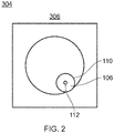
- Figure 2 shows a second example component 304 comprising a cuboidal block having a cylindrical opening 306 extending therethrough.
- Figure 2 also shows an abrasive tool 106 having a substantially cylindrical outer abrading surface 110 (defined by the outer edges of a plurality of abrasive elements mounted on a hub of the tool 106) and a shaft 112 which in use is supported and rotated by the tool mount.
- the abrasive tool 106 is positioned to machine a chamfer onto one of the two circular edges of the cylindrical opening 306.
- the second example component 304 may be used for calibrating for abrasion monitoring, as will be described in detail below with respect to Figure 8 .
- Figure 3 shows correlated acceleration and AE signals together with an output signal for an abrasion parameter, in particular a chamfer dimension.
- the units of the acceleration signal are m/s 2 (in examples, the acceleration energy may be expressed in units of g, i.e. 9.81m/s 2 ).
- the units of the AE signal in this example are voltage.
- a root mean square, time-averaged AE signal is obtained based on the output of the voltage output of the AE sensor.
- the chamfer dimension is shown in units of mm.
- Each of the signals is shown against an X-axis corresponding to positions around the inner circular edge of the component 304 of Figure 2 .
- the units of the X-axis correspond to six locations around the opening that are angularly separated by 60°.
- a correlation can be observed between the acceleration signal and the chamfer dimension when the chamfer dimension is relatively high (e.g. at locations 4 to 6).
- a correlation can be observed between the AE signal and the chamfer dimension when the chamfer dimension is relatively low (e.g. at locations 1 to 3).
- the correlations may be difficult to observe and interpret based on each individual signal, but the applicant has found that the fuzzy inference system (FIS) process is capable of discerning the correlation and accurately predicting the output variable (i.e. chamfer dimension), as will be described below.
- FIS fuzzy inference system
- the chamfer dimension is one example of an abrasion parameter that can be determined by the controller 202.
- Other example abrasion properties include a rate of material removal during abrasive machining, and a surface roughness, as will be described below.
- a method of determining an abrasion parameter and of controlling an abrasive machining operation will now be described with reference to Figures 4 to 7 .
- the methods will be described with respect to the example abrasive machining apparatus 100, abrasion monitoring apparatus 200 and component 304 described above with respect to Figures 1 to 2 .
- fuzzy inference systems have previously employed in optimisation and control algorithms, for example in manufacturing.
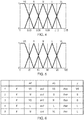
- Figure 4 shows a plot of example triangular-shape membership functions for an acceleration signal.
- the X-axis represents the range of acceleration signal values that are expected to be experienced in use, and in this example extends from 0g (i.e. 0m/s 2 ) to 0.15g (i.e. approximately 1.5m/s 2 ).
- the example triangular membership functions are designated VS (very small), S (small), M (medium), L (large) and VL (very large) and extend over overlapping portions of the range of acceleration values.
- a particular crisp value for the acceleration signal i.e. a single scalar value as sampled from an acceleration signal, such as 0.05g
- a crisp value of 0.05g falls within both the S and M membership functions.
- Truth values can be determined for each membership value.
- the truth value may correspond to how closely the input variable (in this example a crisp value of the acceleration signal) corresponds to a representative value in the membership function, such as a central value.
- a truth value of between 0 and 1 may be determined based on relationships that define the shape of the membership function. For example, a truth value of 1 is obtained for the S membership function when the crisp value for acceleration is 0.045g, and the truth value linearly decreases towards 0 for acceleration values increasing and decreasing from 0.045g to limits at 0.06g and 0.03g respectively. Accordingly, it will be appreciated that the truth value for an acceleration value of 0.05g will be higher for the S membership function than for the M membership function.
- Figure 5 shows a plot of example triangular-shape membership functions for the AE signal which are similar to those for the acceleration signal.
- the process of determining if an input variable falls within a membership function may be referred to as fuzzification of the input variable.
- Figure 6 shows a selection of a set of rules, for example 5 rules of a set of 25 rules, which can be evaluated based on the membership functions, to determine an output variable Y, for example a chamfer dimension in units of mm.
- the first rule shown in Figure 6 specifies that if the AE signal is VS (very small) and the acceleration signal is VS (very small), then the output variable Y is VS (very small).
- each of the signals may belong to more than one membership function, and therefore several rules of the plurality of rules may be satisfied.
- the output variable Y may have similar membership functions, such as VS, S, M, L, VL, to those described above with respect to the input variables of the AE signal and the acceleration signal.
- a plurality of rules within a set of rules may determine that the output variable falls within the same or different membership functions. For example, two rules may determine the output variable to be within the VS membership function, and two further rules may determine the output variable to be within the S membership function.
- a de-fuzzification process is applied to determine a crisp (i.e. scalar) value for the output variable, such as the chamfer dimension.
- a scalar value for each rule may be determined based on the truth value or values of the input membership functions, for example by mapping the lowest truth function of the input variables (in the case of an AND logical definition) to the respective membership function and determining a crisp value accordingly.
- the scalar values may then be averaged, for example by a weighted average with different weights applying to each of the rules.
- truth values may be used to perform a "centroid defuzzification" based on overlapping membership functions for the output variable as is known in the art, to determine a crisp value for the output variable.
- fuzzy inference system as broadly described above enables quick and computationally inexpensive evaluation based on rules which may be determined based on empirical observations and optimisation, rather than by pure derivation from theoretical engineering relationships which may be difficult to compute. Such evaluations may be rapid to compute once the parameters of the respective rules are established.
- an output variable may be determined based on the input variables without use of a fuzzy inference system.
- a neural network may be provided to map between the input variables and the output variable, or a database comprising multi-dimensional look-up tables may be provided.
- Figure 7 shows an example method 700 of abrasive machining.
- instructions for machining a component are defined.
- the instructions are defined for abrasive machining of the component 304 to form a chamfer on the circular edge of the opening 306 having a dimension of 1.5mm (i.e. the distance by which the chamfer separates the cylindrical surface of the opening from the planar surface on the square face of the component as shown in Figure 2 ).
- the instructions are defined so that the abrasive tool 106, which in this example is a rotary compliant abrasive tool, engages the edge to form a chamfer that is inclined by 45° with respect to each of the two adjacent surfaces.
- the instructions are defined so that the controller 108 causes the rotary adjacent tool to traverse around the circular edge until the chamfer dimension is 1.5mm around the entire edge.
- the rotary abrasive tool may initially traverse at a uniform speed of approximately 30mm/s, measured based on the path of the rotating axis of the tool.
- the controller 108 causes a portion of the machining operation to be conducted based on the machining instructions whilst the accelerometer 206 and AE sensor 208 are generating the respective acceleration and AE signals respectively.
- the portion represents a single sampling period for abrasion monitoring, in particular 25ms.
- a force sensor 210 and a respective force signal may also be used.
- the acceleration and AE signals (blocks 706, 708) are sampled by the controller 202 of the abrasion monitoring apparatus 200, for example at respective frequencies of 40kHz and 100kHZ, and based on the sampling over the 25ms sampling period an energy calculation is performed for each signal to determine a crisp (i.e. scalar) acceleration value relating to the energy of the acceleration signal over the sampling period, and a crisp AE value relating to the energy of the AE signal over the sampling period.
- a crisp (i.e. scalar) acceleration value relating to the energy of the acceleration signal over the sampling period
- a crisp AE value relating to the energy of the AE signal over the sampling period.
- the fuzzy inference module 204 determines within which of a plurality of respective membership functions defined for the fuzzy inference method the respective crisp values lie. This step is referred to as fuzzification of the input variables. For example, it may be determined that the crisp acceleration value lies within both the VS and S membership functions with respective truth values of 0.7 and 0.25.
- a plurality of FIS (Fuzzy Inference System) rules as previously determined are applied based on the fuzzy input variables by the fuzzy inference module 204.
- FIS Fuzzy Inference System
- some rules may apply to only one input variable, or more than two input variables.
- a force fuzzy input variable corresponding to the force acting between the tool 106 and the component 304 may be provided, and different rules may be based on combinations of one, two, three or more fuzzy input variables including fuzzy input variables for acceleration, AE and force.
- the output variable of each of the FIS rules are combined, for example based on a weighted average scheme using predetermined weights for each rule, and an abrasion parameter is thereby determined (block 718) by the fuzzy inference module 204.
- the abrasion parameter 718 is then used in a feedback loop for the abrasive machining process as controlled by the controller 108.
- a feedback loop is implemented to first determine whether machining is to be terminated (block 720), and if not, determining whether the machining instructions are to be modified (block 722).
- the feedback loop may be controlled by either the controller 108 of the abrasive machining apparatus 100, by the controller 202 of the abrasion monitoring apparatus, a combination of the two or by an integrated controller (i.e. controlling both machining and monitoring).
- the abrasion parameter (such as chamfer dimension) may be used to determine an end point for an abrasive machining operation. For example, if machining is being conducted at a single location, an abrasion parameter for that location can be monitored and machining can be terminated (block 724) when the abrasion parameter reaches a threshold value (such as a desired chamfer dimension or surface roughness).
- a threshold value such as a desired chamfer dimension or surface roughness
- machining is to be conducted around the perimeter of the circular edge of the component 304 in a plurality of locations, and so instructions to determine whether to terminate machining in block 720 are defined so that the machining operation is only terminated when machining is determined to be completed in all locations, as will be described in further detail below.
- the abrasive tool 106 is controlled to traverse over the circular edge at a uniform rate until machining is complete.
- the abrasion parameter is used to monitor the progress of the machining operation by monitoring how the chamfer dimension changes at a plurality of locations around the circular edge. For example, initially the chamfer dimension may be highly variable around the circular edge, for example, between 0mm and 0.5mm. Accordingly, different locations may require different amounts of machining.
- the abrasion parameter is used to determine if the instructions for the machining operation are to be modified.
- the instructions for the machining operation are initially defined so that the abrasive tool moves around the perimeter of the circular edge at a uniform rate.
- a distribution of the abrasion parameter (in this example, the chamfer dimension) is determined.
- the rate at which the abrasive tool is controlled to traverse around the edge is adjusted based on the distribution of the abrasion parameter, for example so that the abrasive tool 106 traverses at a slower rate over regions with a relatively low chamfer dimension, and traverses at a faster rate over regions with a relatively high chamfer dimension.
- other control parameters may be adjusted, such as a force at which the abrasive tool is applied against the component (for example, the force may be selectively reduced or increased to adjust the rate of abrasion).
- the machining instructions are modified or redefined once per revolution of the circular edge. Therefore, if a full revolution has not yet been completed, then it is determined in block 722 that no modification of the machining instructions is required and the method proceeds to conduct the next portion of the machining operation in block 704. The loop continues accordingly. When a full revolution is complete, it is determined at block 722 that modification of the machining instructions is required, and the machining instructions are redefined in block 702 based on the feedback of the abrasion parameter around the perimeter of the circular edge.
- the abrasive tool 106 may be configured to remain at a first location until machining is complete at that location and before moving to a second location (and so forth). Accordingly, in such examples the machining instructions may be redefined in block 722 to cause movement to the second location only once machining is determined to be completed at the first location, based on the abrasion parameter.
- the abrasion parameter may be different.
- the abrasion parameter may be a surface roughness
- the machining instructions may be defined so that abrasive machining continues over a surface until all parts of the surface have a surface roughness below a predetermined threshold roughness.
- the abrasion parameter may be a rate of material removal, and the machining instructions may be defined to achieve a predetermined profile of material removal, for example based on a previous geometric analysis of a component which identifies how much material is to be removed at different locations on a component.
- the calibration method 800 will be described with reference to the abrasion monitoring apparatus 200 of Figure 1 and the component 304 of Figure 2 .
- machining instructions are defined to cause the abrasive tool 106 to traverse one revolution around the circular edge of the opening 306 of the component 304.
- the acceleration signal 804 and the AE signal 806 are determined and these are supplied as input variables to an FIS model 808 which is initially defined based on a baseline set of rules.
- the baseline set of rules may be defined so that there is a rule for each permutation of the respective membership functions of the input variables. For example, if there are five membership functions for each input variable, and two input variables are used, then there will be 25 rules.
- the baseline set of rules may initially be assumed to have an equal weighting.
- the abrasion parameter which in this example is the chamfer dimension, is predicted based on the FIS model 808 and the input variables.
- empirical abrasion parameter data is determined by inspection of the component.
- a laser measurement device may be used to determine the chamfer dimension as is known in the art.
- the abrasion parameter may be different and the empirical abrasion parameter data may be determined using alternative tools accordingly.
- a profilometer may be used.
- an apparatus may be provided to capture material removed during machining to determine the mass of material removed, for example by weighing the material.
- an error calculation is performed to determine the error between the abrasion parameter predicted by the FIS model 808 and the empirical abrasion parameter.
- the error may be provided to an optimisation sequence for the FIS rules, for example based on genetic algorithms as will be briefly described below.
- the error is set as the objective function for a genetic algorithm optimisation procedure for determining the weights of the rules.
- the fitness of a chromosome that determines the weights of the rules is determined based on the objective function.
- the chromosome is adapted based on genetic algorithm procedures as are known in the art, to determine new weights for the FIS model 808.
- a new FIS prediction 810 is thus determined and a new error calculation 812 is determined based on a comparison with the pre-determined abrasion parameter data (i.e. without repeating abrasive machining), which is again provided as the objective function for optimisation.
- the parameters for the FIS model are determined by genetic algorithm optimisation, to automatically arrive at a set of FIS parameters that calibrate the FIS model 808 based on the abrasion parameter data.
- the chromosome is decoded (block 824) and the FIS model parameters (in particular the weights for the respective rules) are stored.
- Calibration may occur for each different abrasion parameter to be monitored, resulting in different model parameters for each abrasion parameter. Further, calibration may be conducted for different materials (component or abrasive), and different types of tools.
- an FIS model calibrated for chamfer dimension based on the component 304 can be applied for monitoring abrasion of other components having different geometries.
- abrasion parameter such as surface roughness, a chamfer dimension or a material removal rate. Accordingly, it becomes possible to monitor and adjust an abrasive machining process, for example to modify an abrasion force, a path or speed of an abrasion tool, or termination of abrasive machining based on feedback from monitoring without interrupting machining, and/or without removing an abrasive tool from a location on a component being monitored. Accordingly, machining times may be reduced, accuracy may be improved, machining errors may be reduced (e.g. by enabling continuous monitoring), and manual interaction with abrasive machining equipment for periodic inspection may be reduced.
- indirect monitoring may be of particular benefit for abrasive machining, since abrasive tools may be compliant. Accordingly, it may not be possible to predict abrasion parameters such as a chamfer dimension based on relative positioning of a tool mount and a component alone, since the response of the compliant surface of the abrasive tool, and therefore a modified profile of the component, may not be predictable.
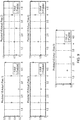
- FIG. 9 shows FIS prediction vs empirical data for chamfer dimension over a number of different passes of the component 304, which demonstrates an accurate match. The applicant has found an accuracy of over 95% using this method.
- abrasion monitoring may be conducted in isolation to abrasive machining.
- abrasion monitoring may be conducted independently of the control of an abrasive machining process. This may be useful, for example, if an abrasive machining process is to be repeated for multiple different components, and may only practicably be modified after machining of a particular component is complete. Therefore, abrasion monitoring may provide useful data for modification of a repeatable process.
- An example controller may include at least one processor and at least one memory.
- the memory may store a computer program comprising computer readable instructions that, when ready by the processor, causes the performance of at least one of the methods described herein with respect to Figures 7 and 8 .
- the computer program may be software or firmware, or may be a combination of software and firmware.
- the processor may include at least one microprocessor and may comprise a single core processor, may comprise multiple processor cores (such as a dual core processor or a quad core processor), or may comprise a plurality of processors (at least one of which may comprise multiple processor cores).
- the memory may be any suitable non-transitory computer (or machine) readable storage medium, data storage device or devices, and may comprise a hard disk and/or solid state memory (such as flash memory).
- the memory may be permanent non-removable memory, or may be removable memory (such as a universal serial bus (USB) flash drive).
- USB universal serial bus
- a non-transitory machine readable storage medium 1002 may be provided including machine-readable instructions 1004 (or a computer program) executable by a processor 1006 to cause performance of at least one of the methods described herein with respect to Figures 7 and 8 .
- the machine-readable instructions may be transferred from the non-transitory machine-readable storage medium 1002 to a memory of a controller or computer, such as the controller 202 of Figure 1 .
- the non-transitory machine-readable storage medium 1002 may be, for example, a USB flash drive, a compact disc (CD), a digital versatile disc (DVD) or a Blu-ray disc.
- the machine-readable instructions may be transferred to a memory via a wireless signal or via a wired signal.
- machine-readable instructions or computer program may be transmitted by a signal that, when executed by a processor, causes the performance of at least one of the methods described herein with respect to Figures 7 and 8 .
Landscapes
- Engineering & Computer Science (AREA)
- Mechanical Engineering (AREA)
- Physics & Mathematics (AREA)
- Acoustics & Sound (AREA)
- Constituent Portions Of Griding Lathes, Driving, Sensing And Control (AREA)
- Finish Polishing, Edge Sharpening, And Grinding By Specific Grinding Devices (AREA)
- Machine Tool Sensing Apparatuses (AREA)
Abstract
Description
- The present disclosure concerns a method and apparatus for monitoring abrasive machining.
- Abrasive machining methods such as grinding, deburring and linishing are used in the final stages of component manufacture to achieve a desired finish, geometry or to remove unwanted features or artefacts from a component. Machining may be interrupted to inspect the component, for example to measure the surface roughness or component geometry.
- According to a first aspect there is provided a method of monitoring abrasion of a component during abrasive machining, the method comprising: generating an acceleration signal corresponding to movement of the component or of an abrasive tool in response to abrasive machining of the component by the tool; generating an acoustic emission signal corresponding to acoustic waves emitted from within the component; and determining an abrasion parameter relating to the removal of material from the component based on a set of input variables including the acceleration signal and the acoustic emission signal.
- The acceleration signal may be generated by an accelerometer coupled to the component. The accelerometer may be a multi-axis accelerometer configured to generate an acceleration signal corresponding to an absolute magnitude of acceleration independent of acceleration direction.
- The acceleration signal may be generated by an accelerometer coupled to the abrasive tool. For example, the accelerometer may be a single-axis accelerometer. For example, if the abrasive tool is a rotary tool, the accelerometer may be coupled to the abrasive tool (or a mount therefor) and configured to generate an acceleration signal corresponding to acceleration along a direction orthogonal to the rotational axis of the tool. The accelerometer may be configured to generate an acceleration signal corresponding to a magnitude of acceleration in a plane normal to the rotational axis of the tool.
- The method may further comprise: generating a force signal corresponding to a force acting between the abrasive tool and the component. The set of input variables may include the force signal. The force signal may be generated by a force sensor coupled to the tool.
- The abrasion parameter may be selected from the group consisting of: a material removal parameter relating to the rate at which material is removed from the component by abrasion; a chamfer dimension parameter relating to a dimension of a chamfer formed by abrasion; and a surface roughness parameter relating to a surface roughness of the component.
- The chamfer dimension parameter may relate to the distance by which two surfaces are separated by the chamfer. The chamfer dimension parameter may relate to the distance by which two surfaces are separated by the chamfer at the location where the tool is engaged with the component. It will be appreciated that the chamfer dimension parameter may vary along an elongate extent of the chamfer.
- The abrasion parameter may be determined by a fuzzy inference module configured to determine the abrasion parameter by evaluating a plurality of fuzzy logic rules based on the set of input variables. The rules may be based on each input variable of the set of input variables. Each rule may be based on each input variable of the set of input variables. The fuzzy inference module may be configured to sample each signal in the set of input variables and determine whether a crisp value derived from the sampled signal falls within each of a plurality of membership functions for the respective signal. For example, a crisp value may fall within a membership function if it is within upper and lower bounds for the membership function. The fuzzy inference system (FIS) may determine a truth value corresponding to how closely the crisp value matches the membership function. For example, a crisp value corresponding to the median value within a range defined for the membership function may result in a truth value of 1.
- The fuzzy inference system may be configured to evaluate a plurality of rules based on the membership functions for each of the input variables, each rule defining whether a an outcome variable (i.e. the abrasion parameter) lies within one of a plurality of membership functions for the outcome variable. A truth value for the outcome variable (in this example the abrasion parameter) may be determined based on the truth variables determined for the membership functions of the input variables.
- A crisp value of the outcome variable may be determined based on the determined truth values and membership functions for each of the plurality of rules. For example, a crisp value may be determined based on a centroid calculation for each of the truth values of the membership functions.
- According to a second aspect there is provided a method of abrasive machining, comprising: causing an abrasive tool to engage a component to conduct an abrasive machining operation; monitoring abrasion of the component in accordance with the first aspect to determine an abrasion parameter; and controlling the abrasive machining operation based on the abrasion parameter.
- The abrasive tool may be a compliant abrasive tool. In other words, the tool may have one or more resilient elements configured to engage a component to abrade the component.
- At least one of a tool engagement force; a path of relative movement of the abrasive tool over the component; and a residence time of the tool at a first location of the component may be controlled based on the abrasion parameter. Controlling the abrasive machining operation may comprise comparing a value of the abrasion parameter for a first location of the component determined by monitoring with a target value for the first location.
- The abrasive machining operation may be selected from the group consisting of: linishing; deburring; surface grinding; and edge grinding.
- According to a third aspect there is provided an apparatus comprising: a tool mount for supporting an abrasive tool to engage a component; an accelerometer for generating an acceleration signal corresponding to movement of the component or movement of the abrasive tool in response to abrasive machining of the component by the tool; an acoustic emission sensor for generating an acoustic emission signal corresponding to acoustic waves emitted from within the component in response to abrasive machining of the component by the tool; and a controller configured to determine an abrasion parameter relating to the removal of material from the component based on a set of inputs including the acceleration signal and the acoustic emission signal. The abrasion parameter may be determined based on each of the set of inputs.
- The accelerometer and/or the acoustic emission sensor may be configured to be coupled to the component. In use, the accelerometer and/or the acoustic emission sensor may be coupled to the component.
- The apparatus may further comprise: a force sensor coupled to the tool mount and configured to output a force signal corresponding to a force acting between an abrasive tool supported by the tool mount and a component with which it is engaged in us. The controller may be configured to determine the abrasion parameter based on a set of inputs including the force signal. In other words, the abrasive tool may be coupled to, attached to or received in the tool mount for engaging a component.
- The controller may be configured to determine the abrasion parameter by evaluating a plurality of fuzzy logic rules based on the set of input variables.
- The tool mount may be for supporting a rotary abrasive tool. The tool mount may be configured to rotate the rotary abrasive tool. For example, the mount may include a chuck for supporting a rotary abrasive tool. The apparatus may further comprise a compliant abrasive tool supported by the tool mount. The compliant abrasive tool may comprise a rotary compliant abrasive tool, for example a flap-wheel comprising a plurality of fins of abrasive material extending from a hub. The compliant abrasive tool may comprise a belt of abrasive material supported on a circulating path, for example, for linishing, deburring or grinding.
- According to a fourth aspect there is provided a non-transitory machine-readable storage medium encoded with instructions executable by a processor, including instructions to: receive an acceleration signal corresponding to movement of a component or movement of an abrasive tool in response to abrasive machining of the component by the tool; receive an acoustic emission signal corresponding to acoustic waves emitted from within the component during abrasive machining of the component; determine an abrasion parameter relating to the removal of material from the component based on a set of inputs including the acceleration signal and the acoustic emission signal.
- The instructions may include instructions to receive a force signal corresponding to a force acting between the abrasive tool and the component during abrasive machining. The set of inputs may include the force signal.
- The skilled person will appreciate that except where mutually exclusive, a feature described in relation to any one of the above aspects may be applied mutatis mutandis to any other aspect. Furthermore except where mutually exclusive any feature described herein may be applied to any aspect and/or combined with any other feature described herein.
- Embodiments will now be described by way of example only, with reference to the Figures, in which:
-
Figure 1 schematically shows an example apparatus for abrasive machining; -
Figure 2 schematically shows an example test component for calibrating abrasive machining monitoring; -
Figure 3 is a plot showing correlated example input variables and an example abrasion parameter. -
Figure 4 is an illustration of membership functions for an acceleration energy signal; -
Figure 5 is an illustration of membership functions for an acoustic emission energy signal; -
Figure 6 is a table showing example rules of a fuzzy inference system; -
Figure 7 is a flowchart of an abrasive machining and monitoring method; -
Figure 8 is a flowchart of a calibration method for abrasive machining monitoring; -
Figure 9 shows plots of predicted versus empirical abrasion parameters; and -
Figure 10 shows a non-transitory machine readable storage medium and processor. -
Figure 1 shows an exampleabrasive machining apparatus 100, an exampleabrasion monitoring apparatus 200, and anexample component 302 supported on awork platform 300. - In this example, the
abrasive machining apparatus 100 comprises a multi-axisrobotic arm 102 having three degrees of freedom. Therobotic arm 102 comprises, at its distal end, atool mount 104 for supporting anabrasive tool 106. In this particular example, theabrasive tool 106 is a compliant abrasive tool, in particular a rotary compliant abrasive tool such as a flap-wheel having a plurality of fins of abrasive material extending from a rotatable hub. - In other examples, different abrasive tools may be used and may be supported by other supporting apparatus. For example, a linishing tool may comprise a band of abrasive material supported on a circulating path, and such a linishing tool may be supported on a gantry, for example.
- The
apparatus 100 further comprises acontroller 108 configured to control relative movement between thetool 106 and thecomponent 302. In this example, thecontroller 108 is configured to actuate therobotic arm 102 to move in order to effect relative movement between thetool 106 supported by thetool mount 104 and astationary work platform 300 andcomponent 302. However, in other examples, thecontroller 108 may be coupled to a moveable work platform and/or amoveable apparatus 100 to control relative movement therebetween. - The
component 302 shown inFigure 1 is a block of metal, such as mild steel, stainless steel, Inconel alloys and titanium, and theabrasive tool 106 comprises abrasive material such as aluminium oxide.Figure 1 shows theapparatus 100 supporting theabrasive tool 106 to engage an outer edge of thecomponent 302, for example to machine a chamfer onto the edge of thecomponent 302. - The
monitoring apparatus 200 comprises acontroller 202 including afuzzy inference module 204 and a plurality of sensors. In this example, the sensors include anaccelerometer 206, anacoustic emission sensor 208 and aforce sensor 210. In the example arrangement shown inFigure 1 , theaccelerometer 206 is coupled to the component 302 (for example, it may be attached to thecomponent 302 or theplatform 300 by a magnetic mounting). Similarly, the acoustic emission sensor 208 ("AE sensor") may be coupled to the component by a magnetic mounting. A clamp, such as a G-clamp, may be used in place of a magnetic mounting, particularly for non-magnetic components such as those comprising stainless steel. Theforce sensor 210 is coupled to thetool mount 104. - In this example, the
accelerometer 206 is a multi-axis accelerometer. In this particular example, the accelerometer is a three-axis accelerometer, and the absolute magnitude of the acceleration energy is determined from the accelerometer, rather than an acceleration energy in a particular direction or plane. The acceleration energy is determined based on a voltage output from the accelerometer (for example based on power spectral density using a data acquisition module, or DAQ), and in this example is proportional to the magnitude of acceleration. - The
AE sensor 208 is configured to detect acoustic emission waves which are emitted from within thecomponent 302. Acoustic emission is a phenomenon by which acoustic waves are generated within a solid article in response to forces or stresses occurring within the article, for example during machining or other sources of stress. AE waves therefore differ from conventional acoustic (i.e. sound waves) issued from sources of sound. TheAE sensor 208 may be configured to filter for AE waves based on filtering a for a range of AE wave frequencies, such as between 1 kHz to 100MHz. - In this example, the
force sensor 210 is a three-axis force sensor, and in this example the force signal corresponds to (in particular, is proportional to) the magnitude of the resultant force measured by theforce sensor 210. - The
controller 202 is configured to receive an acceleration signal from theaccelerometer 206, an AE signal from theAE sensor 208 and a force signal from theforce sensor 210. Thefuzzy inference module 204 is configured to determine an abrasion parameter, such as a chamfer dimension, surface roughness or material removal rate, based on at least the acceleration signal and AE signal, as will be described in detail below with respect toFigures 4 to 7 . -
Figure 2 shows asecond example component 304 comprising a cuboidal block having acylindrical opening 306 extending therethrough.Figure 2 also shows anabrasive tool 106 having a substantially cylindrical outer abrading surface 110 (defined by the outer edges of a plurality of abrasive elements mounted on a hub of the tool 106) and ashaft 112 which in use is supported and rotated by the tool mount. In this example, theabrasive tool 106 is positioned to machine a chamfer onto one of the two circular edges of thecylindrical opening 306. - The
second example component 304 may be used for calibrating for abrasion monitoring, as will be described in detail below with respect toFigure 8 . -
Figure 3 shows correlated acceleration and AE signals together with an output signal for an abrasion parameter, in particular a chamfer dimension. The units of the acceleration signal are m/s2 (in examples, the acceleration energy may be expressed in units of g, i.e. 9.81m/s2). The units of the AE signal in this example are voltage. In particular, a root mean square, time-averaged AE signal is obtained based on the output of the voltage output of the AE sensor. The chamfer dimension is shown in units of mm. - Each of the signals is shown against an X-axis corresponding to positions around the inner circular edge of the
component 304 ofFigure 2 . The units of the X-axis correspond to six locations around the opening that are angularly separated by 60°. In this particular example, a correlation can be observed between the acceleration signal and the chamfer dimension when the chamfer dimension is relatively high (e.g. atlocations 4 to 6). Further, a correlation can be observed between the AE signal and the chamfer dimension when the chamfer dimension is relatively low (e.g. atlocations 1 to 3). The correlations may be difficult to observe and interpret based on each individual signal, but the applicant has found that the fuzzy inference system (FIS) process is capable of discerning the correlation and accurately predicting the output variable (i.e. chamfer dimension), as will be described below. - The chamfer dimension is one example of an abrasion parameter that can be determined by the
controller 202. Other example abrasion properties include a rate of material removal during abrasive machining, and a surface roughness, as will be described below. - A method of determining an abrasion parameter and of controlling an abrasive machining operation will now be described with reference to
Figures 4 to 7 . For the purposes of illustration only, the methods will be described with respect to the exampleabrasive machining apparatus 100,abrasion monitoring apparatus 200 andcomponent 304 described above with respect toFigures 1 to 2 . - Principles of a fuzzy inference method will first be described with respect to
Figures 4 to 6 , and a machining and monitoring method will be described with respect toFigure 7 . - The principles of fuzzy inference systems have previously employed in optimisation and control algorithms, for example in manufacturing.
-
Figure 4 shows a plot of example triangular-shape membership functions for an acceleration signal. The X-axis represents the range of acceleration signal values that are expected to be experienced in use, and in this example extends from 0g (i.e. 0m/s2) to 0.15g (i.e. approximately 1.5m/s2). The example triangular membership functions are designated VS (very small), S (small), M (medium), L (large) and VL (very large) and extend over overlapping portions of the range of acceleration values. Accordingly, a particular crisp value for the acceleration signal (i.e. a single scalar value as sampled from an acceleration signal, such as 0.05g) may lie within two or more membership functions. For example, a crisp value of 0.05g falls within both the S and M membership functions. - Truth values can be determined for each membership value. The truth value may correspond to how closely the input variable (in this example a crisp value of the acceleration signal) corresponds to a representative value in the membership function, such as a central value. In the case of triangular-shape membership functions, a truth value of between 0 and 1 may be determined based on relationships that define the shape of the membership function. For example, a truth value of 1 is obtained for the S membership function when the crisp value for acceleration is 0.045g, and the truth value linearly decreases towards 0 for acceleration values increasing and decreasing from 0.045g to limits at 0.06g and 0.03g respectively. Accordingly, it will be appreciated that the truth value for an acceleration value of 0.05g will be higher for the S membership function than for the M membership function.
-
Figure 5 shows a plot of example triangular-shape membership functions for the AE signal which are similar to those for the acceleration signal. - The process of determining if an input variable falls within a membership function may be referred to as fuzzification of the input variable.
-
Figure 6 shows a selection of a set of rules, for example 5 rules of a set of 25 rules, which can be evaluated based on the membership functions, to determine an output variable Y, for example a chamfer dimension in units of mm. - For example, the first rule shown in
Figure 6 specifies that if the AE signal is VS (very small) and the acceleration signal is VS (very small), then the output variable Y is VS (very small). As mentioned above, each of the signals may belong to more than one membership function, and therefore several rules of the plurality of rules may be satisfied. - The output variable Y may have similar membership functions, such as VS, S, M, L, VL, to those described above with respect to the input variables of the AE signal and the acceleration signal.
- Accordingly, a plurality of rules within a set of rules may determine that the output variable falls within the same or different membership functions. For example, two rules may determine the output variable to be within the VS membership function, and two further rules may determine the output variable to be within the S membership function.
- A de-fuzzification process is applied to determine a crisp (i.e. scalar) value for the output variable, such as the chamfer dimension. In particular, a scalar value for each rule may be determined based on the truth value or values of the input membership functions, for example by mapping the lowest truth function of the input variables (in the case of an AND logical definition) to the respective membership function and determining a crisp value accordingly. The scalar values may then be averaged, for example by a weighted average with different weights applying to each of the rules.
- In other examples, the truth values may be used to perform a "centroid defuzzification" based on overlapping membership functions for the output variable as is known in the art, to determine a crisp value for the output variable.
- The use of a fuzzy inference system as broadly described above enables quick and computationally inexpensive evaluation based on rules which may be determined based on empirical observations and optimisation, rather than by pure derivation from theoretical engineering relationships which may be difficult to compute. Such evaluations may be rapid to compute once the parameters of the respective rules are established.
- In other examples, an output variable may be determined based on the input variables without use of a fuzzy inference system. For example, a neural network may be provided to map between the input variables and the output variable, or a database comprising multi-dimensional look-up tables may be provided.
-
Figure 7 shows anexample method 700 of abrasive machining. Inblock 702, instructions for machining a component are defined. In this example, the instructions are defined for abrasive machining of thecomponent 304 to form a chamfer on the circular edge of theopening 306 having a dimension of 1.5mm (i.e. the distance by which the chamfer separates the cylindrical surface of the opening from the planar surface on the square face of the component as shown inFigure 2 ). The instructions are defined so that theabrasive tool 106, which in this example is a rotary compliant abrasive tool, engages the edge to form a chamfer that is inclined by 45° with respect to each of the two adjacent surfaces. - In this example, the instructions are defined so that the
controller 108 causes the rotary adjacent tool to traverse around the circular edge until the chamfer dimension is 1.5mm around the entire edge. For example, the rotary abrasive tool may initially traverse at a uniform speed of approximately 30mm/s, measured based on the path of the rotating axis of the tool. - In
block 704, thecontroller 108 causes a portion of the machining operation to be conducted based on the machining instructions whilst theaccelerometer 206 andAE sensor 208 are generating the respective acceleration and AE signals respectively. In this example, the portion represents a single sampling period for abrasion monitoring, in particular 25ms. In other examples, aforce sensor 210 and a respective force signal may also be used. - The acceleration and AE signals (
blocks 706, 708) are sampled by thecontroller 202 of theabrasion monitoring apparatus 200, for example at respective frequencies of 40kHz and 100kHZ, and based on the sampling over the 25ms sampling period an energy calculation is performed for each signal to determine a crisp (i.e. scalar) acceleration value relating to the energy of the acceleration signal over the sampling period, and a crisp AE value relating to the energy of the AE signal over the sampling period. - In blocks 710 and 712, the
fuzzy inference module 204 determines within which of a plurality of respective membership functions defined for the fuzzy inference method the respective crisp values lie. This step is referred to as fuzzification of the input variables. For example, it may be determined that the crisp acceleration value lies within both the VS and S membership functions with respective truth values of 0.7 and 0.25. - In block 714, a plurality of FIS (Fuzzy Inference System) rules as previously determined are applied based on the fuzzy input variables by the
fuzzy inference module 204. In this particular example, there are 25 rules each operating on both an acceleration fuzzy input variable and an AE fuzzy input variable. In other examples, some rules may apply to only one input variable, or more than two input variables. In yet further example methods, a force fuzzy input variable corresponding to the force acting between thetool 106 and thecomponent 304 may be provided, and different rules may be based on combinations of one, two, three or more fuzzy input variables including fuzzy input variables for acceleration, AE and force. - In
block 716, the output variable of each of the FIS rules are combined, for example based on a weighted average scheme using predetermined weights for each rule, and an abrasion parameter is thereby determined (block 718) by thefuzzy inference module 204. - The
abrasion parameter 718 is then used in a feedback loop for the abrasive machining process as controlled by thecontroller 108. In this example, a feedback loop is implemented to first determine whether machining is to be terminated (block 720), and if not, determining whether the machining instructions are to be modified (block 722). The feedback loop may be controlled by either thecontroller 108 of theabrasive machining apparatus 100, by thecontroller 202 of the abrasion monitoring apparatus, a combination of the two or by an integrated controller (i.e. controlling both machining and monitoring). - In example methods, the abrasion parameter (such as chamfer dimension) may be used to determine an end point for an abrasive machining operation. For example, if machining is being conducted at a single location, an abrasion parameter for that location can be monitored and machining can be terminated (block 724) when the abrasion parameter reaches a threshold value (such as a desired chamfer dimension or surface roughness).
- When machining is being conducted over a plurality of locations, as in the present example, it may only be appropriate to terminate the machining operation when machining is already complete at all other locations.
- In this particular example, machining is to be conducted around the perimeter of the circular edge of the
component 304 in a plurality of locations, and so instructions to determine whether to terminate machining inblock 720 are defined so that the machining operation is only terminated when machining is determined to be completed in all locations, as will be described in further detail below. - In this example, the
abrasive tool 106 is controlled to traverse over the circular edge at a uniform rate until machining is complete. The abrasion parameter is used to monitor the progress of the machining operation by monitoring how the chamfer dimension changes at a plurality of locations around the circular edge. For example, initially the chamfer dimension may be highly variable around the circular edge, for example, between 0mm and 0.5mm. Accordingly, different locations may require different amounts of machining. - In
block 722, the abrasion parameter is used to determine if the instructions for the machining operation are to be modified. As described above, the instructions for the machining operation are initially defined so that the abrasive tool moves around the perimeter of the circular edge at a uniform rate. After at least one cycle of the edge, a distribution of the abrasion parameter (in this example, the chamfer dimension) is determined. In one example, the rate at which the abrasive tool is controlled to traverse around the edge is adjusted based on the distribution of the abrasion parameter, for example so that theabrasive tool 106 traverses at a slower rate over regions with a relatively low chamfer dimension, and traverses at a faster rate over regions with a relatively high chamfer dimension. In other examples, other control parameters may be adjusted, such as a force at which the abrasive tool is applied against the component (for example, the force may be selectively reduced or increased to adjust the rate of abrasion). - In this particular example, the machining instructions are modified or redefined once per revolution of the circular edge. Therefore, if a full revolution has not yet been completed, then it is determined in
block 722 that no modification of the machining instructions is required and the method proceeds to conduct the next portion of the machining operation inblock 704. The loop continues accordingly. When a full revolution is complete, it is determined atblock 722 that modification of the machining instructions is required, and the machining instructions are redefined inblock 702 based on the feedback of the abrasion parameter around the perimeter of the circular edge. - In other examples, the
abrasive tool 106 may be configured to remain at a first location until machining is complete at that location and before moving to a second location (and so forth). Accordingly, in such examples the machining instructions may be redefined inblock 722 to cause movement to the second location only once machining is determined to be completed at the first location, based on the abrasion parameter. - Whilst the above example has been described with respect to an abrasion parameter which is a chamfer dimension, it will be appreciated that in other examples the abrasion parameter may be different. For example, the abrasion parameter may be a surface roughness, and the machining instructions may be defined so that abrasive machining continues over a surface until all parts of the surface have a surface roughness below a predetermined threshold roughness. Further, in other examples the abrasion parameter may be a rate of material removal, and the machining instructions may be defined to achieve a predetermined profile of material removal, for example based on a previous geometric analysis of a component which identifies how much material is to be removed at different locations on a component.
- A method of calibrating a monitoring apparatus and/or a controller or machine-readable instructions for such a monitoring apparatus will now be described with reference to
Figure 8 . - For the purposes of illustration, the
calibration method 800 will be described with reference to theabrasion monitoring apparatus 200 ofFigure 1 and thecomponent 304 ofFigure 2 . - In
block 802, machining instructions are defined to cause theabrasive tool 106 to traverse one revolution around the circular edge of theopening 306 of thecomponent 304. During machining, theacceleration signal 804 and the AE signal 806 are determined and these are supplied as input variables to anFIS model 808 which is initially defined based on a baseline set of rules. For example, the baseline set of rules may be defined so that there is a rule for each permutation of the respective membership functions of the input variables. For example, if there are five membership functions for each input variable, and two input variables are used, then there will be 25 rules. The baseline set of rules may initially be assumed to have an equal weighting. - In
block 810, the abrasion parameter, which in this example is the chamfer dimension, is predicted based on theFIS model 808 and the input variables. - In
block 814, empirical abrasion parameter data is determined by inspection of the component. For example, a laser measurement device may be used to determine the chamfer dimension as is known in the art. In other examples the abrasion parameter may be different and the empirical abrasion parameter data may be determined using alternative tools accordingly. For example, when the abrasion parameter is surface roughness, a profilometer may be used. Further, when the abrasion parameter is material removal rate, an apparatus may be provided to capture material removed during machining to determine the mass of material removed, for example by weighing the material. - In
block 812, an error calculation is performed to determine the error between the abrasion parameter predicted by theFIS model 808 and the empirical abrasion parameter. The error may be provided to an optimisation sequence for the FIS rules, for example based on genetic algorithms as will be briefly described below. - In
block 818, the error is set as the objective function for a genetic algorithm optimisation procedure for determining the weights of the rules. Inblock 820, the fitness of a chromosome that determines the weights of the rules is determined based on the objective function. - In
block 822, it is determined if the fitness of the chromosome, based on the objective function, is at a maximum. This may be determined to occur when there is no change between a predetermined number of optimisation cycles. If the fitness is not at a maximum, then inblock 816 the chromosome is adapted based on genetic algorithm procedures as are known in the art, to determine new weights for theFIS model 808. - A
new FIS prediction 810 is thus determined and anew error calculation 812 is determined based on a comparison with the pre-determined abrasion parameter data (i.e. without repeating abrasive machining), which is again provided as the objective function for optimisation. - By proceeding in this loop, the parameters for the FIS model (in particular the weighting of the outcomes of the different rules) are determined by genetic algorithm optimisation, to automatically arrive at a set of FIS parameters that calibrate the
FIS model 808 based on the abrasion parameter data. - When it is determined that the fitness of the GA chromosome is at a maximum, the chromosome is decoded (block 824) and the FIS model parameters (in particular the weights for the respective rules) are stored.
- Calibration may occur for each different abrasion parameter to be monitored, resulting in different model parameters for each abrasion parameter. Further, calibration may be conducted for different materials (component or abrasive), and different types of tools.
- However, the applicant has found that the FIS model performs consistently for different geometry types. Accordingly, an FIS model calibrated for chamfer dimension based on the
component 304 can be applied for monitoring abrasion of other components having different geometries. - By monitoring a plurality of parameters, in particular acceleration (of the component), acoustic emission (AE) from within the component and optionally a force acting between the component and an abrasive tool, the applicant has found that it is possible to indirectly monitor an abrasion parameter such as surface roughness, a chamfer dimension or a material removal rate. Accordingly, it becomes possible to monitor and adjust an abrasive machining process, for example to modify an abrasion force, a path or speed of an abrasion tool, or termination of abrasive machining based on feedback from monitoring without interrupting machining, and/or without removing an abrasive tool from a location on a component being monitored. Accordingly, machining times may be reduced, accuracy may be improved, machining errors may be reduced (e.g. by enabling continuous monitoring), and manual interaction with abrasive machining equipment for periodic inspection may be reduced.
- Further, such indirect monitoring may be of particular benefit for abrasive machining, since abrasive tools may be compliant. Accordingly, it may not be possible to predict abrasion parameters such as a chamfer dimension based on relative positioning of a tool mount and a component alone, since the response of the compliant surface of the abrasive tool, and therefore a modified profile of the component, may not be predictable.
- Although none of the input variables described above (i.e. acceleration, acoustic emission and force) have been shown to individually present a direct or linear correlation with abrasion parameters such as surface roughness, chamfer dimension and material removal rate, the applicant has found that their combination (in particular, of at least acceleration and acoustic emission data), together with suitable optimisation of FIS rules, results in reliable prediction independent of component geometry. By way of example,
Figure 9 shows FIS prediction vs empirical data for chamfer dimension over a number of different passes of thecomponent 304, which demonstrates an accurate match. The applicant has found an accuracy of over 95% using this method. - Although examples have been described in which a method of abrasive machining is controlled based on feedback from abrasion monitoring, it will be appreciated that in examples, abrasion monitoring may be conducted in isolation to abrasive machining. For example, abrasion monitoring may be conducted independently of the control of an abrasive machining process. This may be useful, for example, if an abrasive machining process is to be repeated for multiple different components, and may only practicably be modified after machining of a particular component is complete. Therefore, abrasion monitoring may provide useful data for modification of a repeatable process.
- It will be appreciated that the methods described herein with respect to
Figures 1 to 9 may be at least partly implemented in a computer, such as a general purpose computer, or in an apparatus comprising a controller configured to implement the methods. - An example controller may include at least one processor and at least one memory. The memory may store a computer program comprising computer readable instructions that, when ready by the processor, causes the performance of at least one of the methods described herein with respect to
Figures 7 and8 . The computer program may be software or firmware, or may be a combination of software and firmware. - The processor may include at least one microprocessor and may comprise a single core processor, may comprise multiple processor cores (such as a dual core processor or a quad core processor), or may comprise a plurality of processors (at least one of which may comprise multiple processor cores).
- The memory may be any suitable non-transitory computer (or machine) readable storage medium, data storage device or devices, and may comprise a hard disk and/or solid state memory (such as flash memory). The memory may be permanent non-removable memory, or may be removable memory (such as a universal serial bus (USB) flash drive).
- As shown in
Figure 10 , a non-transitory machinereadable storage medium 1002 may be provided including machine-readable instructions 1004 (or a computer program) executable by aprocessor 1006 to cause performance of at least one of the methods described herein with respect toFigures 7 and8 . The machine-readable instructions may be transferred from the non-transitory machine-readable storage medium 1002 to a memory of a controller or computer, such as thecontroller 202 ofFigure 1 . The non-transitory machine-readable storage medium 1002 may be, for example, a USB flash drive, a compact disc (CD), a digital versatile disc (DVD) or a Blu-ray disc. In some examples, the machine-readable instructions may be transferred to a memory via a wireless signal or via a wired signal. - Further, the machine-readable instructions or computer program may be transmitted by a signal that, when executed by a processor, causes the performance of at least one of the methods described herein with respect to
Figures 7 and8 . - It will be understood that the invention is not limited to the embodiments above-described and various modifications and improvements can be made without departing from the concepts described herein. Except where mutually exclusive, any of the features may be employed separately or in combination with any other features and the disclosure extends to and includes all combinations and sub-combinations of one or more features described herein.
Claims (15)
- A method of monitoring abrasion of a component during abrasive machining, the method comprising:generating an acceleration signal corresponding to movement of the component or of an abrasive tool in response to abrasive machining of the component by the tool;generating an acoustic emission signal corresponding to acoustic waves emitted from within the component;determining an abrasion parameter relating to the removal of material from the component based on a set of input variables including the acceleration signal and the acoustic emission signal.
- The method according to Claim 1, further comprising:generating a force signal corresponding to a force acting between the abrasive tool and the component; andwherein the set of input variables includes the force signal.
- The method according to Claim 1 or Claim 2, wherein the abrasion parameter is selected from the group consisting of:a material removal parameter relating to the rate at which material is removed from the component by abrasion;a chamfer dimension parameter relating to a dimension of a chamfer formed by abrasion; anda surface roughness parameter relating to a surface roughness of the component.
- The method according to any preceding claim, wherein the abrasion parameter is determined by a fuzzy inference module configured to determine the abrasion parameter by evaluating a plurality of fuzzy logic rules based on the set of input variables.
- A method of abrasive machining, comprising:causing an abrasive tool to engage a component to conduct an abrasive machining operation;monitoring abrasion of the component in accordance with any one of the preceding claims to determine an abrasion parameter;controlling the abrasive machining operation based on the abrasion parameter.
- The method according to Claim 5, wherein at least one of a tool engagement force; a path of relative movement of the abrasive tool over the component; and a residence time of the tool at a first location of the component is controlled based on the abrasion parameter.
- The method according to Claim 5 or Claim 6, wherein controlling the abrasive machining operation comprises comparing a value of the abrasion parameter for a first location of the component determined by monitoring with a target value for the first location.
- The method according to any one of Claims 5 to 7, wherein the abrasive machining operation is selected from the group consisting of:linishing;deburring;surface grinding; andedge grinding.
- An apparatus comprising:a tool mount for supporting an abrasive tool to engage a component;an accelerometer for generating an acceleration signal corresponding to movement of the component or movement of the abrasive tool in response to abrasive machining of the component by the tool;an acoustic emission sensor for generating an acoustic emission signal corresponding to acoustic waves emitted from within the component in response to abrasive machining of the component by the tool; anda controller configured to determine an abrasion parameter relating to the removal of material from the component based on a set of inputs including the acceleration signal and the acoustic emission signal.
- The apparatus according to Claim 9, wherein the accelerometer and/or the acoustic emission sensor is configured to be coupled to the component.
- The apparatus according to Claim 9 or Claim 10, further comprising:a force sensor coupled to the tool mount and configured to output a force signal corresponding to a force acting between an abrasive tool supported by the tool mount and a component with which it is engaged in use;wherein the controller is configured to determine the abrasion parameter based on a set of inputs including the force signal.
- The apparatus according to any of Claims 9 to 11, wherein the tool mount is for supporting a rotary abrasive tool.
- The apparatus according to any one of Claims 9 to 12, further comprising a compliant abrasive tool supported by the tool mount.
- A non-transitory machine-readable storage medium encoded with instructions executable by a processor, including instructions to:receive an acceleration signal corresponding to movement of a component or movement of an abrasive tool in response to abrasive machining of the component by the tool;receive an acoustic emission signal corresponding to acoustic waves emitted from within the component during abrasive machining of the component;determine an abrasion parameter relating to the removal of material from the component based on a set of inputs including the acceleration signal and the acoustic emission signal.
- The non-transitory machine-readable storage medium according to Claim 14, including instructions to:receive a force signal corresponding to a force acting between the abrasive tool and the component during abrasive machining; andwherein the set of inputs includes the force signal.
Applications Claiming Priority (1)
| Application Number | Priority Date | Filing Date | Title |
|---|---|---|---|
| GBGB1614685.4A GB201614685D0 (en) | 2016-08-31 | 2016-08-31 | Method and apparatus for monitoring abrasive machining |
Publications (2)
| Publication Number | Publication Date |
|---|---|
| EP3290156A2 true EP3290156A2 (en) | 2018-03-07 |
| EP3290156A3 EP3290156A3 (en) | 2018-07-18 |
Family
ID=57119972
Family Applications (1)
| Application Number | Title | Priority Date | Filing Date |
|---|---|---|---|
| EP17184674.4A Withdrawn EP3290156A3 (en) | 2016-08-31 | 2017-08-03 | Method and apparatus for monitoring abrasive machining |
Country Status (4)
| Country | Link |
|---|---|
| US (1) | US20180056480A1 (en) |
| EP (1) | EP3290156A3 (en) |
| GB (1) | GB201614685D0 (en) |
| SG (1) | SG10201706573RA (en) |
Cited By (3)
| Publication number | Priority date | Publication date | Assignee | Title |
|---|---|---|---|---|
| LU101065B1 (en) * | 2018-12-21 | 2020-06-24 | Univ Luxembourg | Machining system and monitoring method |
| CN113159139A (en) * | 2021-04-01 | 2021-07-23 | 哈尔滨工业大学 | Damage state diagnosis method based on improved acoustic emission density clustering |
| EP3976315A1 (en) * | 2019-05-27 | 2022-04-06 | Robert Bosch GmbH | Method for determining state information relating to a belt grinder by means of a machine learning system |
Families Citing this family (13)
| Publication number | Priority date | Publication date | Assignee | Title |
|---|---|---|---|---|
| EP3374128B1 (en) * | 2015-11-10 | 2020-12-30 | ABB Schweiz AG | A method and system for machining, and a robot system |
| DE102019207745A1 (en) * | 2019-05-27 | 2020-12-03 | Robert Bosch Gmbh | Method for detecting information provided on a grinding belt |
| JP7120512B2 (en) * | 2019-11-22 | 2022-08-17 | Smc株式会社 | Trajectory control device |
| US11328505B2 (en) * | 2020-02-18 | 2022-05-10 | Verizon Connect Development Limited | Systems and methods for utilizing models to identify a vehicle accident based on vehicle sensor data and video data captured by a vehicle device |
| CN111855467B (en) * | 2020-07-31 | 2023-10-20 | 矿冶科技集团有限公司 | Abradable coating performance test system and method for precisely calibrating rub-impact zero point |
| CN111855384B (en) * | 2020-07-31 | 2023-10-17 | 矿冶科技集团有限公司 | Abradable coating performance testing system and method for efficient calculation of penetration depth ratio |
| DE102021100314A1 (en) * | 2021-01-11 | 2022-07-14 | Aktiebolaget Skf | Machining unit and method for machining a component |
| CN114406807B (en) * | 2022-01-28 | 2023-02-14 | 上海交通大学 | Abrasive belt grinding material removal rate prediction method, device, equipment and storage medium |
| CN115609479A (en) * | 2022-10-20 | 2023-01-17 | 中国中材海外科技发展有限公司 | Monitoring method, device, system and storage medium of grinding equipment |
| CN117207070B (en) * | 2023-09-01 | 2024-04-23 | 四川普什宁江机床有限公司 | Automatic grinding wheel dressing method based on numerical control machine tool |
| CN117381547A (en) * | 2023-10-18 | 2024-01-12 | 哈尔滨工业大学 | A method and system for predicting the wear status of small-diameter ball-head grinding wheels based on a combination of feature dimensionality reduction and radial basis neural network |
| GB202317161D0 (en) * | 2023-11-09 | 2023-12-27 | Rolls Royce Plc | Polishing system and method of polishing component |
| CN120038606B (en) * | 2025-04-25 | 2025-09-12 | 北京科技大学 | Multi-energy field regulation and control process method and system for improving service life of aerospace complex component |
Citations (1)
| Publication number | Priority date | Publication date | Assignee | Title |
|---|---|---|---|---|
| US20040115841A1 (en) * | 2001-09-20 | 2004-06-17 | Molnar Charles J. | In situ finishing aid control |
Family Cites Families (11)
| Publication number | Priority date | Publication date | Assignee | Title |
|---|---|---|---|---|
| US4866429A (en) * | 1987-08-12 | 1989-09-12 | Scientific Atlanta, Inc. | Automated machine tool monitoring device |
| US5044125A (en) * | 1988-09-02 | 1991-09-03 | Cincinnati Milacron-Heald Corp. | Method and apparatus for controlling grinding processes |
| US5566092A (en) * | 1993-12-30 | 1996-10-15 | Caterpillar Inc. | Machine fault diagnostics system and method |
| US5643051A (en) * | 1995-06-16 | 1997-07-01 | The University Of Connecticut | Centerless grinding process and apparatus therefor |
| JP3702496B2 (en) * | 1995-07-10 | 2005-10-05 | 三菱電機株式会社 | Machining method using numerical controller |
| US20130189801A1 (en) * | 1998-11-06 | 2013-07-25 | Semcon Tech, Llc | Advanced finishing control |
| US6494765B2 (en) * | 2000-09-25 | 2002-12-17 | Center For Tribology, Inc. | Method and apparatus for controlled polishing |
| US6257953B1 (en) * | 2000-09-25 | 2001-07-10 | Center For Tribology, Inc. | Method and apparatus for controlled polishing |
| US7537511B2 (en) * | 2006-03-14 | 2009-05-26 | Micron Technology, Inc. | Embedded fiber acoustic sensor for CMP process endpoint |
| CN101670553B (en) * | 2009-09-28 | 2012-07-11 | 浙江大学 | External grinding multiparameter integrated quality monitoring device and method |
| US20140067321A1 (en) * | 2012-09-06 | 2014-03-06 | Schmitt Industries, Inc. | Systems and methods for monitoring machining of a workpiece |
-
2016
- 2016-08-31 GB GBGB1614685.4A patent/GB201614685D0/en not_active Ceased
-
2017
- 2017-08-03 EP EP17184674.4A patent/EP3290156A3/en not_active Withdrawn
- 2017-08-11 US US15/674,751 patent/US20180056480A1/en not_active Abandoned
- 2017-08-11 SG SG10201706573RA patent/SG10201706573RA/en unknown
Patent Citations (1)
| Publication number | Priority date | Publication date | Assignee | Title |
|---|---|---|---|---|
| US20040115841A1 (en) * | 2001-09-20 | 2004-06-17 | Molnar Charles J. | In situ finishing aid control |
Cited By (7)
| Publication number | Priority date | Publication date | Assignee | Title |
|---|---|---|---|---|
| LU101065B1 (en) * | 2018-12-21 | 2020-06-24 | Univ Luxembourg | Machining system and monitoring method |
| WO2020128090A1 (en) * | 2018-12-21 | 2020-06-25 | Université Du Luxembourg | Machining system and monitoring method |
| US11801579B2 (en) | 2018-12-21 | 2023-10-31 | Université Du Luxembourg | Machining system and monitoring method |
| EP3976315A1 (en) * | 2019-05-27 | 2022-04-06 | Robert Bosch GmbH | Method for determining state information relating to a belt grinder by means of a machine learning system |
| US12397392B2 (en) | 2019-05-27 | 2025-08-26 | Robert Bosch Gmbh | Method for determining state information relating to a belt grinder by means of a machine learning system |
| CN113159139A (en) * | 2021-04-01 | 2021-07-23 | 哈尔滨工业大学 | Damage state diagnosis method based on improved acoustic emission density clustering |
| CN113159139B (en) * | 2021-04-01 | 2022-08-09 | 哈尔滨工业大学 | Damage state diagnosis method based on improved acoustic emission density clustering |
Also Published As
| Publication number | Publication date |
|---|---|
| EP3290156A3 (en) | 2018-07-18 |
| SG10201706573RA (en) | 2018-03-28 |
| GB201614685D0 (en) | 2016-10-12 |
| US20180056480A1 (en) | 2018-03-01 |
Similar Documents
| Publication | Publication Date | Title |
|---|---|---|
| EP3290156A2 (en) | Method and apparatus for monitoring abrasive machining | |
| Arizmendi et al. | Modelling and analysis of surface topography generated in face milling operations | |
| TWI873175B (en) | Method for monitoring machining process, finishing machine for machining and relevant computer program and computer-readable medium | |
| US9830559B2 (en) | Machine learning unit, spindle replacement judging device, controller, machine tool, production system, and machine learning method, which are able to judge necessity of spindle replacement | |
| EP2740568B1 (en) | Automated polishing systems and methods | |
| US20210229231A1 (en) | Machine tool machining dimensions prediction device, machine tool equipment abnormality determination device, machine tool machining dimensions prediction system, and machine tool machining dimensions prediction method | |
| WO2013150905A1 (en) | Machining system and method | |
| EP3736648A1 (en) | Method for autonomous optimization of a grinding process | |
| JP2017037640A (en) | Machine tool path compensation using vibration sensing | |
| WO2012169300A1 (en) | Working abnormality detecting device and working abnormality detecting method for machine tool | |
| JP2010105073A (en) | Method and device for suppressing vibration of machine tool | |
| CN108398920B (en) | Servo control device | |
| CN112775731B (en) | Grinding system | |
| SE1450617A1 (en) | Procedure for grinding a workpiece and procedure for determining process parameters | |
| CN114577453A (en) | Method for determining damage of a component, computer program, digital storage medium and control unit | |
| US9849547B2 (en) | Manufacturing apparatus and manufacturing method for manufacturing less unbalanced blower blade | |
| JP2017209743A (en) | Machining device | |
| Jenkins et al. | Adaptive pole-zero cancellation in grinding force control | |
| TW201515095A (en) | Matching method for matching two plasma reactors | |
| Saikumar et al. | Development of a feed rate adaption control system for high-speed rough and finish end-milling of hardened EN24 steel | |
| JP5768485B2 (en) | Sphere polishing equipment | |
| Alatorre et al. | Closed loop force control of in-situ machining robots using audible sound features | |
| JP2023520154A (en) | Dental machining system for generating process parameters for machining | |
| JP6235167B2 (en) | Processing equipment | |
| CN101322084A (en) | Method and control device for determining a maintenance interval of a machine element |
Legal Events
| Date | Code | Title | Description |
|---|---|---|---|
| PUAI | Public reference made under article 153(3) epc to a published international application that has entered the european phase |
Free format text: ORIGINAL CODE: 0009012 |
|
| STAA | Information on the status of an ep patent application or granted ep patent |
Free format text: STATUS: THE APPLICATION HAS BEEN PUBLISHED |
|
| AK | Designated contracting states |
Kind code of ref document: A2 Designated state(s): AL AT BE BG CH CY CZ DE DK EE ES FI FR GB GR HR HU IE IS IT LI LT LU LV MC MK MT NL NO PL PT RO RS SE SI SK SM TR |
|
| AX | Request for extension of the european patent |
Extension state: BA ME |
|
| PUAL | Search report despatched |
Free format text: ORIGINAL CODE: 0009013 |
|
| AK | Designated contracting states |
Kind code of ref document: A3 Designated state(s): AL AT BE BG CH CY CZ DE DK EE ES FI FR GB GR HR HU IE IS IT LI LT LU LV MC MK MT NL NO PL PT RO RS SE SI SK SM TR |
|
| AX | Request for extension of the european patent |
Extension state: BA ME |
|
| RIC1 | Information provided on ipc code assigned before grant |
Ipc: B24B 49/16 20060101ALI20180608BHEP Ipc: B24B 49/00 20120101AFI20180608BHEP Ipc: B24B 37/005 20120101ALI20180608BHEP |
|
| STAA | Information on the status of an ep patent application or granted ep patent |
Free format text: STATUS: REQUEST FOR EXAMINATION WAS MADE |
|
| STAA | Information on the status of an ep patent application or granted ep patent |
Free format text: STATUS: EXAMINATION IS IN PROGRESS |
|
| 17P | Request for examination filed |
Effective date: 20190115 |
|
| RBV | Designated contracting states (corrected) |
Designated state(s): AL AT BE BG CH CY CZ DE DK EE ES FI FR GB GR HR HU IE IS IT LI LT LU LV MC MK MT NL NO PL PT RO RS SE SI SK SM TR |
|
| 17Q | First examination report despatched |
Effective date: 20190214 |
|
| RAP1 | Party data changed (applicant data changed or rights of an application transferred) |
Owner name: ROLLS-ROYCE PLC |
|
| GRAP | Despatch of communication of intention to grant a patent |
Free format text: ORIGINAL CODE: EPIDOSNIGR1 |
|
| STAA | Information on the status of an ep patent application or granted ep patent |
Free format text: STATUS: GRANT OF PATENT IS INTENDED |
|
| INTG | Intention to grant announced |
Effective date: 20200720 |
|
| STAA | Information on the status of an ep patent application or granted ep patent |
Free format text: STATUS: THE APPLICATION IS DEEMED TO BE WITHDRAWN |
|
| 18D | Application deemed to be withdrawn |
Effective date: 20201201 |