EP3288749B1 - Folding arm for a sidewall band of a tyre, arms mechanism and drum apparatus - Google Patents
Folding arm for a sidewall band of a tyre, arms mechanism and drum apparatus Download PDFInfo
- Publication number
- EP3288749B1 EP3288749B1 EP16723266.9A EP16723266A EP3288749B1 EP 3288749 B1 EP3288749 B1 EP 3288749B1 EP 16723266 A EP16723266 A EP 16723266A EP 3288749 B1 EP3288749 B1 EP 3288749B1
- Authority
- EP
- European Patent Office
- Prior art keywords
- folding
- folding arm
- arm
- head portion
- rod
- Prior art date
- Legal status (The legal status is an assumption and is not a legal conclusion. Google has not performed a legal analysis and makes no representation as to the accuracy of the status listed.)
- Active
Links
Images



Classifications
-
- B—PERFORMING OPERATIONS; TRANSPORTING
- B29—WORKING OF PLASTICS; WORKING OF SUBSTANCES IN A PLASTIC STATE IN GENERAL
- B29D—PRODUCING PARTICULAR ARTICLES FROM PLASTICS OR FROM SUBSTANCES IN A PLASTIC STATE
- B29D30/00—Producing pneumatic or solid tyres or parts thereof
- B29D30/06—Pneumatic tyres or parts thereof (e.g. produced by casting, moulding, compression moulding, injection moulding, centrifugal casting)
- B29D30/08—Building tyres
- B29D30/20—Building tyres by the flat-tyre method, i.e. building on cylindrical drums
- B29D30/32—Fitting the bead-rings or bead-cores; Folding the textile layers around the rings or cores
-
- B—PERFORMING OPERATIONS; TRANSPORTING
- B29—WORKING OF PLASTICS; WORKING OF SUBSTANCES IN A PLASTIC STATE IN GENERAL
- B29D—PRODUCING PARTICULAR ARTICLES FROM PLASTICS OR FROM SUBSTANCES IN A PLASTIC STATE
- B29D30/00—Producing pneumatic or solid tyres or parts thereof
- B29D30/06—Pneumatic tyres or parts thereof (e.g. produced by casting, moulding, compression moulding, injection moulding, centrifugal casting)
- B29D30/08—Building tyres
- B29D30/20—Building tyres by the flat-tyre method, i.e. building on cylindrical drums
- B29D30/32—Fitting the bead-rings or bead-cores; Folding the textile layers around the rings or cores
- B29D2030/3221—Folding over means, e.g. bladders or rigid arms
- B29D2030/3264—Folding over means, e.g. bladders or rigid arms using radially expandable, contractible mechanical means, e.g. circumferentially spaced arms, spring rollers, cages
Definitions
- the present invention refers in general to the building of tyres and, in particular, to a drum apparatus for building tyres and some of its components.
- tyre many types of tyre, so called of the turn-up type, require that elements such as the carcass ply/plies and/or the sidewall band(s) be folded towards the outside of the tyre, in order to be anchored to the metallic rings and thereby laid against the sidewall itself.
- This folding and extending operation around the rings and on the sidewall of the tyre is typically performed with a drum apparatus which is provided with a movable arms mechanism that, during the assembly steps - before vulcanization - will correctly position these elements.
- sidewall band of a sidewall of a tyre means a set of sheets, even of different rubbers, that forms the sidewall of the tyre.
- the sidewall band of a sidewall of a tyre in particular its end portion that is intended to be extended onto the sidewall of the tyre, is normally made of a particularly soft rubbery material, precisely to facilitate its adhesion to the sidewall of the tyre.
- the band during the setting step before the arms mechanism has been able to position it correctly, will assume irregular positions due to unwanted folds in the rubber itself and will ultimately interfere with the arms themselves of the mechanism.
- the softness of the rubber of which the band is made facilitates this folding-in on itself and, further, the rubber can adhere to the metal of the arms with consequent positioning irregularities or even breakage during the operation of the arms mechanism. In these cases, the result is obviously a defective product which certainly needs to be discarded.
- JP2011230414 discloses an apparatus for manufacturing a pneumatic tire of which the bead part is enhanced in structural durability.
- the apparatus comprises a plurality of shaking arms which include a plurality of the shakable arm bodies provided in the circumferential direction of the molding drum and carcass ply pressing rollers.
- EP2204277 discloses a device for folding the body ply capable of turning up both width-end portions of a body ply by an even pressing force wherein a plurality of arm components is circumferentially arranged to be movable in the axial direction of an operating shaft.
- DE102006018508 discloses an apparatus for turning up a tire structure member on a tire building drum with a roller lever wherein, spaced apart by spacing means the roller is substantially exclusively in contact with the tire structure member part to be assembled.
- EP2243623 discloses a folding mechanism including two folding rollers, which are fitted in a swingable manner to a folding finger so as to hold deviated positions of a carcass band in a circumferential direction and in a meridian direction.
- the technical problem addressed and solved by the present invention is therefore to provide an arm for an arms mechanism of a drum for building tyres that minimizes the possibility of contact with the rubber of the sidewall bands and/or of the carcass plies during the positioning step.
- a further object of the present invention is an arms mechanism as defined in dependent claim 12.
- Yet another object of the present invention is a drum for building tyres as defined in dependent claim 13.
- figure 1A is a view of an arms mechanism.
- the mechanism is seen in section, showing only one arm.
- the mechanism comprises a plurality of arms, mounted in such a way as to form a substantially cylindrical body.
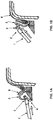
- Each arm 1, during the operation of the mechanism is moved in such a way that its folding end 2 follows the profile of the tyre extending the sidewall band 3 and/or the carcass plies 6 along the sidewall of the tyre itself.
- Figure 1A highlights the way in which an edge of a sidewall band 3, for example the outermost one, could - at least under certain circumstances - come into contact with the arm 1 itself, or else with the roller carrier assembly 4.
- Such contact can easily lead to situations such as the one shown in figure 1B , where the edge of the sidewall band 3 then folds itself under the rollers assuming an unwanted position and unwanted creases along the sidewall of the tyre.
- This can also occur because the edge of the band 3 comes into contact with the roller 5, which, due to its clockwise direction of rotation during operation, promotes the abnormal folding of the band 3 upon itself by dragging it.
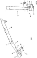
- figure 2 is a side view of a folding arm 10 according to the present invention, while figure 3 is a perspective view of said arm.
- the arm 10 comprises a rod 11 of length L that has pivoting connection means 12 to a connection end 13 thereof.
- the length L of the rod is predetermined by and depends largely on the size of the arms mechanism upon which the arm is mounted and then ultimately on the size of the drum for building tyres upon which the mechanism is mounted.
- This length L will therefore vary according to the type and size of the tyre that is to be built.
- a folding assembly 20, which comprises a support 21 and more than one folding roller 22, 23 idle mounted on said support 21, is pivotally connected at a head end 14 of the rod 11.
- the support 21 has a chevron-like shape in its front view and preferably the pivotal connection of the support 21 is provided at the substantially central part thereof.
- the two arms of the chevron-like support 21 have different lengths.
- the support 21 is pivotally connected to the head end 14 of the rod 11 the shorter arm of the chevron-like support 21 is disposed closer to the head end 14 and the rod 11 and the longer arm of the chevron-like support 21 is reaching away from the head end 14 of the rod 11.
- the support 21 can be made of metal, such as steel.
- the rollers have the task of sliding during operation along the sidewall of the tyre, while extending the carcass ply 3.
- These are typically made of nylon and/or steel.
- the rod 11 of the arm 10 has a main portion 15 having a linear longitudinal development along a first development line PD.
- the rod 11 comprises a head portion 16 having a linear longitudinal development along a second development line HD.
- the main portion 15 and the head portion 16 fit together at an interface section 17.
- the configuration of the head portion 16 and its orientation with respect to the main portion 15 of the rod 11, is such that, during use, the probability of the edge of the sidewall band 3 coming into contact with the upper part of the arm and/or with one of the folding rollers is minimized or even zeroed.
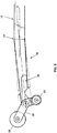
- figure 3 is a perspective view of the arm 10, while figure 4 is a view from above of a portion of the arm itself.
- Figure 4 shows in detail the particular of the folding assembly 20 comprising the support 21 upon which the folding rollers 22, 23 are idle mounted.
- the head portion 16 is such that it has a section area 18 at the head end 14, which is less than the area of said interface section 17.
- the section area 18 at said head end 16 is less than or equal to 90% of the area of the interface section 17.
- the inclination angle ⁇ , between the second development line HD and the first development line PD, is preferably greater than 0° and smaller than 40°.
- the inclination angle ⁇ is greater than 0° and smaller than 10°.
- the head portion 16 has a tapering towards its head end.
- the shape of the head portion 16 can be generically referred to as conical or frustoconical, even though with a base that is inclined with respect to the main axis of the cone.
- the tapering of the head portion 16 can be defined by means of a tapering angle ⁇ , as shown in figure 5 , with respect to a hypothetical cylindrical surface having a base corresponding to the interface section 17.
- this tapering angle ⁇ is between 0.5° and 3°.
- the tapering angle ⁇ is between 0.9° and 1.5° and, according to a preferred embodiment, the tapering angle ⁇ is equal to 1.2°.
- the length L of the rod 11 is a function of the dimensioning of the apparatus for which the arm is intended.
- the head portion 16 had a length HL expressed as a function of the overall length L of the rod.
- the length HL of the head portion is likely to be between 20% and 50% of the length L of the rod 11.
- the configuration of the arm 10, in particular of its head portion 16, is therefore such to minimize the possibility that the edge of the carcass ply will come into contact with the arm itself or with the rollers during use of the apparatus.
- the head portion 16 includes a surface coating made of anti-stick material.
- said anti-stick treatment can be made with SR41D by Smaltiriva ®.
- the head portion 16 may also comprise a stop region 25 for the folding assembly 20.
- the stop region 25, made, for example, in the form of a recess within the head portion 16, is configured in such a way as to constitute a stopping element for the folding assembly 20, for example for the roller 22 or for the support 21, in order to prevent a complete rotation of the assembly itself around its axis of rotation during operation of the apparatus.
- the stop region 25 is configured is such a way as to constitute a stopping element for the folding assembly 20, preferably for the short arm of the chevron-like support 21 or for the roller 22 idle mounted on the short arm of the chevron-like support 21.
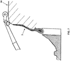
- figure 6 shows an arm 10 according to the present invention, within an arms mechanism mounted on a drum for building tyres, in a resting position, i.e. before being activated for the positioning of the sidewall band 3 of the tyre 30.
- the arm 10 When the apparatus is activated, the arm 10 is pushed forward (according to the arrow F1) and, consequently, the head portion rises up towards the sidewall of the tyre (as indicated by the arrow F2).
- the folding assembly can pass below the edge of the band 3 and then position it on the sidewall while avoiding unwanted folding.
- the subsequent figure 7 shows the final processing step.
- figure 8 schematically shows a drum apparatus 50 for building tyres comprising two arms mechanisms 40, each of which has a plurality of arms according to the present invention.
Landscapes
- Engineering & Computer Science (AREA)
- Mechanical Engineering (AREA)
- Tyre Moulding (AREA)
Description
- The present invention refers in general to the building of tyres and, in particular, to a drum apparatus for building tyres and some of its components.
- As is well known, the building of a tyre requires various steps of assembly for the different tyre components: inner liners, carcass plies, metallic rings, sidewall bands, tread bands, etc.
- In particular, many types of tyre, so called of the turn-up type, require that elements such as the carcass ply/plies and/or the sidewall band(s) be folded towards the outside of the tyre, in order to be anchored to the metallic rings and thereby laid against the sidewall itself.
- This folding and extending operation around the rings and on the sidewall of the tyre is typically performed with a drum apparatus which is provided with a movable arms mechanism that, during the assembly steps - before vulcanization - will correctly position these elements.
- In particular, the term "sidewall band" of a sidewall of a tyre means a set of sheets, even of different rubbers, that forms the sidewall of the tyre.
- The sidewall band of a sidewall of a tyre, in particular its end portion that is intended to be extended onto the sidewall of the tyre, is normally made of a particularly soft rubbery material, precisely to facilitate its adhesion to the sidewall of the tyre.
- It is however possible that during these steps, the band during the setting step, before the arms mechanism has been able to position it correctly, will assume irregular positions due to unwanted folds in the rubber itself and will ultimately interfere with the arms themselves of the mechanism. The softness of the rubber of which the band is made facilitates this folding-in on itself and, further, the rubber can adhere to the metal of the arms with consequent positioning irregularities or even breakage during the operation of the arms mechanism. In these cases, the result is obviously a defective product which certainly needs to be discarded.
-
JP2011230414 -
EP2204277 discloses a device for folding the body ply capable of turning up both width-end portions of a body ply by an even pressing force wherein a plurality of arm components is circumferentially arranged to be movable in the axial direction of an operating shaft. -
DE102006018508 discloses an apparatus for turning up a tire structure member on a tire building drum with a roller lever wherein, spaced apart by spacing means the roller is substantially exclusively in contact with the tire structure member part to be assembled. -
EP2243623 discloses a folding mechanism including two folding rollers, which are fitted in a swingable manner to a folding finger so as to hold deviated positions of a carcass band in a circumferential direction and in a meridian direction. - The technical problem addressed and solved by the present invention is therefore to provide an arm for an arms mechanism of a drum for building tyres that minimizes the possibility of contact with the rubber of the sidewall bands and/or of the carcass plies during the positioning step.
- This is achieved by means of an arm as defined in independent claim 1.
- A further object of the present invention is an arms mechanism as defined in
dependent claim 12. - Yet another object of the present invention is a drum for building tyres as defined in
dependent claim 13. - Further characteristics of the present invention are defined in the corresponding dependent claims.
- The advantages, together with the characteristics and the way of usage of the present invention, will become clear from the following detailed description of its preferred embodiments given purely by way of non-limiting example.
- Reference will be made to the figures of the accompanying drawings, in which:
-
Figures 1A and 1B schematically illustrate the typical defect of the prior art apparatus; -
Figure 2 is a side view of an arm according to the present invention; -
Figure 3 is a perspective view of the arm infigure 2 ; -
Figure 4 is a top view of a portion of the arm infigure 2 ; -
Figure 5 is a side view of a portion of the arm infigure 2 ; -
Figures 6 and7 sequentially illustrate the operation of an arm according to the present invention; and -
Figure 8 is a schematic view of a drum apparatus for building tyres according to the present invention, comprising two arms mechanisms according to the present invention. - Some embodiments of the present invention will be described below, making reference to the above figures.
- With initial reference to
figures 1A and 1B , these schematically illustrate the operativity of a prior art apparatus in which the defect described above is highlighted. - In particular,
figure 1A is a view of an arms mechanism. For simplicity, the mechanism is seen in section, showing only one arm. It is to be understood that the mechanism comprises a plurality of arms, mounted in such a way as to form a substantially cylindrical body. Each arm 1, during the operation of the mechanism is moved in such a way that itsfolding end 2 follows the profile of the tyre extending thesidewall band 3 and/or the carcass plies 6 along the sidewall of the tyre itself. -
Figure 1A highlights the way in which an edge of asidewall band 3, for example the outermost one, could - at least under certain circumstances - come into contact with the arm 1 itself, or else with the roller carrier assembly 4. Such contact can easily lead to situations such as the one shown infigure 1B , where the edge of thesidewall band 3 then folds itself under the rollers assuming an unwanted position and unwanted creases along the sidewall of the tyre. This can also occur because the edge of theband 3 comes into contact with theroller 5, which, due to its clockwise direction of rotation during operation, promotes the abnormal folding of theband 3 upon itself by dragging it. - The subsequent
figure 2 is a side view of afolding arm 10 according to the present invention, whilefigure 3 is a perspective view of said arm. - Firstly, the
arm 10 comprises arod 11 of length L that has pivoting connection means 12 to aconnection end 13 thereof. - The length L of the rod is predetermined by and depends largely on the size of the arms mechanism upon which the arm is mounted and then ultimately on the size of the drum for building tyres upon which the mechanism is mounted.
- This length L will therefore vary according to the type and size of the tyre that is to be built.
- It should however be understood that this length L is not decisive for the purposes of the present invention, in fact, as will become clear below, the same principle can be applied to arms of differing lengths.
- A
folding assembly 20, which comprises asupport 21 and more than onefolding roller support 21, is pivotally connected at ahead end 14 of therod 11. Preferably thesupport 21 has a chevron-like shape in its front view and preferably the pivotal connection of thesupport 21 is provided at the substantially central part thereof. In a preferred embodiment the two arms of the chevron-like support 21 have different lengths. Preferably when thesupport 21 is pivotally connected to thehead end 14 of therod 11 the shorter arm of the chevron-like support 21 is disposed closer to thehead end 14 and therod 11 and the longer arm of the chevron-like support 21 is reaching away from thehead end 14 of therod 11. Thesupport 21 can be made of metal, such as steel. - As is known, the rollers have the task of sliding during operation along the sidewall of the tyre, while extending the
carcass ply 3. These are typically made of nylon and/or steel. - The
rod 11 of thearm 10 has amain portion 15 having a linear longitudinal development along a first development line PD. - In addition, at the
head end 14, therod 11 comprises ahead portion 16 having a linear longitudinal development along a second development line HD. - The
main portion 15 and thehead portion 16 fit together at aninterface section 17. - According to the present invention, the configuration of the
head portion 16 and its orientation with respect to themain portion 15 of therod 11, is such that, during use, the probability of the edge of thesidewall band 3 coming into contact with the upper part of the arm and/or with one of the folding rollers is minimized or even zeroed. - This is achieved in particular by having such a second development line HD inclined by an inclination angle β that is greater than zero with respect to the first development line PD.
- The subsequent
figure 3 is a perspective view of thearm 10, whilefigure 4 is a view from above of a portion of the arm itself.Figure 4 shows in detail the particular of thefolding assembly 20 comprising thesupport 21 upon which thefolding rollers - With reference to
figure 3 , while themain portion 15 can be considered to be substantially cylindrical, advantageously, thehead portion 16 is such that it has asection area 18 at thehead end 14, which is less than the area of saidinterface section 17. - The
section area 18 at saidhead end 16 is less than or equal to 90% of the area of theinterface section 17. - This comprehensively leads to a lower position of the head portion of the arm with respect to the edge of the carcass ply, thereby making it impossible or substantially difficult for the edge to touch the metal of the arm or the folding roller.
- With reference to
figure 5 , the inclination angle β, between the second development line HD and the first development line PD, is preferably greater than 0° and smaller than 40°. - Even more preferably, the inclination angle β is greater than 0° and smaller than 10°.
- According to one embodiment of the present invention, the
head portion 16 has a tapering towards its head end. The shape of thehead portion 16 can be generically referred to as conical or frustoconical, even though with a base that is inclined with respect to the main axis of the cone. - In general, the tapering of the
head portion 16 can be defined by means of a tapering angle α, as shown infigure 5 , with respect to a hypothetical cylindrical surface having a base corresponding to theinterface section 17. - According to an embodiment of the present invention, this tapering angle α is between 0.5° and 3°.
- Preferably, the tapering angle α is between 0.9° and 1.5° and, according to a preferred embodiment, the tapering angle α is equal to 1.2°.
- From a dimensional point of view, as has been mentioned, the length L of the
rod 11 is a function of the dimensioning of the apparatus for which the arm is intended. - However, for the purposes of the present invention, it would be preferable if the
head portion 16 had a length HL expressed as a function of the overall length L of the rod. - According to the preferred embodiment of the invention, the length HL of the head portion is likely to be between 20% and 50% of the length L of the
rod 11. - The configuration of the
arm 10, in particular of itshead portion 16, is therefore such to minimize the possibility that the edge of the carcass ply will come into contact with the arm itself or with the rollers during use of the apparatus. - In any case, advantageously, it can also be provided that the
head portion 16 includes a surface coating made of anti-stick material. - For example, said anti-stick treatment can be made with SR41D by Smaltiriva ®.
- According to a further embodiment, the
head portion 16 may also comprise astop region 25 for thefolding assembly 20. - The
stop region 25, made, for example, in the form of a recess within thehead portion 16, is configured in such a way as to constitute a stopping element for thefolding assembly 20, for example for theroller 22 or for thesupport 21, in order to prevent a complete rotation of the assembly itself around its axis of rotation during operation of the apparatus. In a preferred embodiment thestop region 25 is configured is such a way as to constitute a stopping element for thefolding assembly 20, preferably for the short arm of the chevron-like support 21 or for theroller 22 idle mounted on the short arm of the chevron-like support 21. - The subsequent
figures 6 and7 show, respectively, the initial and the final processing steps. - In particular,
figure 6 shows anarm 10 according to the present invention, within an arms mechanism mounted on a drum for building tyres, in a resting position, i.e. before being activated for the positioning of thesidewall band 3 of thetyre 30. - When the apparatus is activated, the
arm 10 is pushed forward (according to the arrow F1) and, consequently, the head portion rises up towards the sidewall of the tyre (as indicated by the arrow F2). - In this situation, the folding assembly can pass below the edge of the
band 3 and then position it on the sidewall while avoiding unwanted folding. The subsequentfigure 7 shows the final processing step. - Finally,
figure 8 schematically shows adrum apparatus 50 for building tyres comprising twoarms mechanisms 40, each of which has a plurality of arms according to the present invention. - The invention has heretofore been described with reference to its preferred embodiments. It is intended that each of the technical solutions implemented in the preferred embodiments described herein by way of example can advantageously be combined in different ways between them, in order to give form to other embodiments, which belong to the same inventive nucleus and that all fall within the scope of protection afforded by the claims recited hereinafter.
Claims (13)
- Folding arm (10) for a sidewall band (3) of a tyre, comprising:- a rod (1) having pivoting connection means (12) at a connection end (13); and- a folding assembly (20) comprising a support (21) and more than one folding roller (22, 23) idle mounted on said support (21), wherein the support (21) has a chevron-like shape and the assembly being connected to an head end (14) of said rod (11),
wherein said rod (11) has a main portion (15) having a linear longitudinal development along a first development line (PD) and, at said head end (14), an head portion (16) having a linear longitudinal development along a second development line (HD), wherein said second development line (HD) is inclined of an inclination angle (β) greater than zero with respect to said first development line (PD),
said main portion (15) and said head portion (16) fitting together at an interface section (17),
wherein said head portion (16) has a section area (18) at said head end (14), less than the area of said interface section (17), wherein said folding assembly (20) is rotably connected to said head end (14) of said rod (11) and wherein the section area (18) at said head end (14) is lower or equal to 90% of the area of the interface section (17). - Folding arm (10) according to claim 1, wherein said main portion (15) is cylindrical.
- Folding arm (1) according to claim 1 or 2, wherein said inclination angle (β) is greater than 0° and smaller than 40°.
- Folding arm (10) according to claim 3, wherein said inclination angle (β) is greater than 0° and smaller than 10°.
- Folding arm (10) according to anyone of the claims 1 to 4, wherein said head portion (16) is conical or frustoconical.
- Folding arm (10) according to anyone of the claims 1 to 5, wherein said head portion (16) has a tapering towards its head end (14) and a corresponding tapering angle (α).
- Folding arm (10) according to claim 6, wherein said tapering angle (α) is between 0.5° and 3°.
- Folding arm (10) according to claim 7, wherein said tapering angle (α) is between 0.9° and 1.5°.
- Folding arm (10) according to anyone of the claims 1 to 8, wherein said rod (11) has a length (L) and said head portion (16) has a length (HD) between 20% and 50% of the length (L) of said rod (11).
- Folding arm (10) according to anyone of the claims 1 a 9, wherein said head portion (16) comprises a surface coating made of anti-stick material.
- Folding arm (10) according to anyone of the claims 1 to 10, wherein said head portion (16) comprises a stop region (25) for the folding assembly (20).
- Arms mechanism (40) comprising a plurality of folding arms (10) according to anyone of the claims 1 to 11.
- Drum apparatus (50) for building tyres, comprising one or more arms mechanisms (40) according to claim 12.
Applications Claiming Priority (2)
| Application Number | Priority Date | Filing Date | Title |
|---|---|---|---|
| ITRM20150178 | 2015-04-27 | ||
| PCT/EP2016/059298 WO2016174037A1 (en) | 2015-04-27 | 2016-04-26 | Folding arm for a sidewall band of a tyre, arms mechanism and drum apparatus |
Publications (2)
| Publication Number | Publication Date |
|---|---|
| EP3288749A1 EP3288749A1 (en) | 2018-03-07 |
| EP3288749B1 true EP3288749B1 (en) | 2020-11-18 |
Family
ID=53490107
Family Applications (1)
| Application Number | Title | Priority Date | Filing Date |
|---|---|---|---|
| EP16723266.9A Active EP3288749B1 (en) | 2015-04-27 | 2016-04-26 | Folding arm for a sidewall band of a tyre, arms mechanism and drum apparatus |
Country Status (3)
| Country | Link |
|---|---|
| EP (1) | EP3288749B1 (en) |
| BR (1) | BR112017021364B1 (en) |
| WO (1) | WO2016174037A1 (en) |
Families Citing this family (1)
| Publication number | Priority date | Publication date | Assignee | Title |
|---|---|---|---|---|
| MX2019007075A (en) | 2016-12-29 | 2019-09-05 | Pirelli | Apparatus and process for building tyres for vehicle wheels. |
Family Cites Families (7)
| Publication number | Priority date | Publication date | Assignee | Title |
|---|---|---|---|---|
| US2409974A (en) * | 1942-08-06 | 1946-10-22 | Gen Tire & Rubber Co | Tire building machine |
| DE102006018508A1 (en) | 2006-04-21 | 2007-10-25 | Continental Aktiengesellschaft | Device for turning up a tire building part onto a tire building drum |
| WO2009054185A1 (en) | 2007-10-25 | 2009-04-30 | Fuji Seiko Co., Ltd. | Device for folding body ply |
| JP5219272B2 (en) * | 2008-01-28 | 2013-06-26 | 株式会社ブリヂストン | Tire molding equipment |
| NL2001604C2 (en) * | 2008-05-22 | 2009-11-24 | Vmi Epe Holland | Tire building drum for building an unvulcanized tire. |
| JP5513970B2 (en) | 2010-04-28 | 2014-06-04 | 住友ゴム工業株式会社 | Pneumatic tire manufacturing apparatus and pneumatic tire manufacturing method |
| CN203665975U (en) * | 2013-12-30 | 2014-06-25 | 软控股份有限公司 | Mechanical reverse wrapping device |
-
2016
- 2016-04-26 WO PCT/EP2016/059298 patent/WO2016174037A1/en not_active Ceased
- 2016-04-26 BR BR112017021364-8A patent/BR112017021364B1/en active IP Right Grant
- 2016-04-26 EP EP16723266.9A patent/EP3288749B1/en active Active
Non-Patent Citations (1)
| Title |
|---|
| None * |
Also Published As
| Publication number | Publication date |
|---|---|
| BR112017021364B1 (en) | 2021-12-28 |
| BR112017021364A2 (en) | 2018-07-03 |
| EP3288749A1 (en) | 2018-03-07 |
| WO2016174037A1 (en) | 2016-11-03 |
Similar Documents
| Publication | Publication Date | Title |
|---|---|---|
| JP6258627B2 (en) | Sleeveless tire molding drum | |
| JP2012045954A (en) | Method and apparatus for manufacturing reinforcing structure for vehicle tire | |
| EP1537986A1 (en) | Tire manufacturing method, and green tire manufacturing equipment | |
| JP2019503899A (en) | Method and plant for building tires | |
| US6379493B1 (en) | Device for transporting and depositing material strips | |
| US9962891B2 (en) | Method for manufacturing motorcycle tire | |
| CN102574349B (en) | For being configured to process and the equipment of the tire of wheel of vehicle | |
| EP1645403A1 (en) | Method for molding bead portion of green tire and bead portion molding device | |
| CN111331890A (en) | Manufacturing device of eco-friendly tire and manufacturing method of eco-friendly tire | |
| US9102113B2 (en) | Band drum pop-up hinge | |
| JP4914508B2 (en) | Manufacturing method of raw tire for motorcycle | |
| WO2016174037A1 (en) | Folding arm for a sidewall band of a tyre, arms mechanism and drum apparatus | |
| EP2032350B1 (en) | Process and apparatus for manufacturing a pneumatic tyre | |
| US20090133809A1 (en) | Method and tyre building drum for building a tyre | |
| EP3505339A1 (en) | Manufacturing method of tire component and manufacturing device of tire component | |
| EP3205490B1 (en) | Pneumatic tire manufacturing method | |
| JP4603525B2 (en) | Tire molding drum | |
| EP1323517B1 (en) | Method of making a pneumatic tyre | |
| JP6848692B2 (en) | Molding drum | |
| JP2008221719A (en) | Manufacturing method of pneumatic tire and green tire molding apparatus | |
| US11345106B2 (en) | Manufacturing method of tire component and manufacturing device of tire component | |
| JP7040045B2 (en) | Presser for tire molding | |
| US20200164688A1 (en) | Method for manufacturing tire | |
| CN109476106B (en) | Method and apparatus for constructing tires for vehicle wheels | |
| JP6190540B2 (en) | Raw tire molding equipment |
Legal Events
| Date | Code | Title | Description |
|---|---|---|---|
| STAA | Information on the status of an ep patent application or granted ep patent |
Free format text: STATUS: THE INTERNATIONAL PUBLICATION HAS BEEN MADE |
|
| PUAI | Public reference made under article 153(3) epc to a published international application that has entered the european phase |
Free format text: ORIGINAL CODE: 0009012 |
|
| STAA | Information on the status of an ep patent application or granted ep patent |
Free format text: STATUS: REQUEST FOR EXAMINATION WAS MADE |
|
| 17P | Request for examination filed |
Effective date: 20171113 |
|
| AK | Designated contracting states |
Kind code of ref document: A1 Designated state(s): AL AT BE BG CH CY CZ DE DK EE ES FI FR GB GR HR HU IE IS IT LI LT LU LV MC MK MT NL NO PL PT RO RS SE SI SK SM TR |
|
| AX | Request for extension of the european patent |
Extension state: BA ME |
|
| DAV | Request for validation of the european patent (deleted) | ||
| DAX | Request for extension of the european patent (deleted) | ||
| GRAP | Despatch of communication of intention to grant a patent |
Free format text: ORIGINAL CODE: EPIDOSNIGR1 |
|
| STAA | Information on the status of an ep patent application or granted ep patent |
Free format text: STATUS: GRANT OF PATENT IS INTENDED |
|
| INTG | Intention to grant announced |
Effective date: 20200612 |
|
| GRAS | Grant fee paid |
Free format text: ORIGINAL CODE: EPIDOSNIGR3 |
|
| GRAA | (expected) grant |
Free format text: ORIGINAL CODE: 0009210 |
|
| STAA | Information on the status of an ep patent application or granted ep patent |
Free format text: STATUS: THE PATENT HAS BEEN GRANTED |
|
| AK | Designated contracting states |
Kind code of ref document: B1 Designated state(s): AL AT BE BG CH CY CZ DE DK EE ES FI FR GB GR HR HU IE IS IT LI LT LU LV MC MK MT NL NO PL PT RO RS SE SI SK SM TR |
|
| RAP1 | Party data changed (applicant data changed or rights of an application transferred) |
Owner name: BRIDGESTONE EUROPE NV/SA |
|
| REG | Reference to a national code |
Ref country code: GB Ref legal event code: FG4D |
|
| REG | Reference to a national code |
Ref country code: CH Ref legal event code: EP |
|
| REG | Reference to a national code |
Ref country code: IE Ref legal event code: FG4D |
|
| REG | Reference to a national code |
Ref country code: DE Ref legal event code: R096 Ref document number: 602016048039 Country of ref document: DE |
|
| REG | Reference to a national code |
Ref country code: AT Ref legal event code: REF Ref document number: 1335281 Country of ref document: AT Kind code of ref document: T Effective date: 20201215 |
|
| REG | Reference to a national code |
Ref country code: NL Ref legal event code: FP |
|
| REG | Reference to a national code |
Ref country code: AT Ref legal event code: MK05 Ref document number: 1335281 Country of ref document: AT Kind code of ref document: T Effective date: 20201118 |
|
| PG25 | Lapsed in a contracting state [announced via postgrant information from national office to epo] |
Ref country code: PT Free format text: LAPSE BECAUSE OF FAILURE TO SUBMIT A TRANSLATION OF THE DESCRIPTION OR TO PAY THE FEE WITHIN THE PRESCRIBED TIME-LIMIT Effective date: 20210318 Ref country code: RS Free format text: LAPSE BECAUSE OF FAILURE TO SUBMIT A TRANSLATION OF THE DESCRIPTION OR TO PAY THE FEE WITHIN THE PRESCRIBED TIME-LIMIT Effective date: 20201118 Ref country code: NO Free format text: LAPSE BECAUSE OF FAILURE TO SUBMIT A TRANSLATION OF THE DESCRIPTION OR TO PAY THE FEE WITHIN THE PRESCRIBED TIME-LIMIT Effective date: 20210218 Ref country code: FI Free format text: LAPSE BECAUSE OF FAILURE TO SUBMIT A TRANSLATION OF THE DESCRIPTION OR TO PAY THE FEE WITHIN THE PRESCRIBED TIME-LIMIT Effective date: 20201118 Ref country code: GR Free format text: LAPSE BECAUSE OF FAILURE TO SUBMIT A TRANSLATION OF THE DESCRIPTION OR TO PAY THE FEE WITHIN THE PRESCRIBED TIME-LIMIT Effective date: 20210219 |
|
| PG25 | Lapsed in a contracting state [announced via postgrant information from national office to epo] |
Ref country code: SE Free format text: LAPSE BECAUSE OF FAILURE TO SUBMIT A TRANSLATION OF THE DESCRIPTION OR TO PAY THE FEE WITHIN THE PRESCRIBED TIME-LIMIT Effective date: 20201118 Ref country code: BG Free format text: LAPSE BECAUSE OF FAILURE TO SUBMIT A TRANSLATION OF THE DESCRIPTION OR TO PAY THE FEE WITHIN THE PRESCRIBED TIME-LIMIT Effective date: 20210218 Ref country code: PL Free format text: LAPSE BECAUSE OF FAILURE TO SUBMIT A TRANSLATION OF THE DESCRIPTION OR TO PAY THE FEE WITHIN THE PRESCRIBED TIME-LIMIT Effective date: 20201118 Ref country code: LV Free format text: LAPSE BECAUSE OF FAILURE TO SUBMIT A TRANSLATION OF THE DESCRIPTION OR TO PAY THE FEE WITHIN THE PRESCRIBED TIME-LIMIT Effective date: 20201118 Ref country code: IS Free format text: LAPSE BECAUSE OF FAILURE TO SUBMIT A TRANSLATION OF THE DESCRIPTION OR TO PAY THE FEE WITHIN THE PRESCRIBED TIME-LIMIT Effective date: 20210318 Ref country code: AT Free format text: LAPSE BECAUSE OF FAILURE TO SUBMIT A TRANSLATION OF THE DESCRIPTION OR TO PAY THE FEE WITHIN THE PRESCRIBED TIME-LIMIT Effective date: 20201118 |
|
| REG | Reference to a national code |
Ref country code: LT Ref legal event code: MG9D |
|
| PG25 | Lapsed in a contracting state [announced via postgrant information from national office to epo] |
Ref country code: HR Free format text: LAPSE BECAUSE OF FAILURE TO SUBMIT A TRANSLATION OF THE DESCRIPTION OR TO PAY THE FEE WITHIN THE PRESCRIBED TIME-LIMIT Effective date: 20201118 |
|
| PG25 | Lapsed in a contracting state [announced via postgrant information from national office to epo] |
Ref country code: CZ Free format text: LAPSE BECAUSE OF FAILURE TO SUBMIT A TRANSLATION OF THE DESCRIPTION OR TO PAY THE FEE WITHIN THE PRESCRIBED TIME-LIMIT Effective date: 20201118 Ref country code: EE Free format text: LAPSE BECAUSE OF FAILURE TO SUBMIT A TRANSLATION OF THE DESCRIPTION OR TO PAY THE FEE WITHIN THE PRESCRIBED TIME-LIMIT Effective date: 20201118 Ref country code: LT Free format text: LAPSE BECAUSE OF FAILURE TO SUBMIT A TRANSLATION OF THE DESCRIPTION OR TO PAY THE FEE WITHIN THE PRESCRIBED TIME-LIMIT Effective date: 20201118 Ref country code: SM Free format text: LAPSE BECAUSE OF FAILURE TO SUBMIT A TRANSLATION OF THE DESCRIPTION OR TO PAY THE FEE WITHIN THE PRESCRIBED TIME-LIMIT Effective date: 20201118 Ref country code: SK Free format text: LAPSE BECAUSE OF FAILURE TO SUBMIT A TRANSLATION OF THE DESCRIPTION OR TO PAY THE FEE WITHIN THE PRESCRIBED TIME-LIMIT Effective date: 20201118 Ref country code: RO Free format text: LAPSE BECAUSE OF FAILURE TO SUBMIT A TRANSLATION OF THE DESCRIPTION OR TO PAY THE FEE WITHIN THE PRESCRIBED TIME-LIMIT Effective date: 20201118 |
|
| REG | Reference to a national code |
Ref country code: DE Ref legal event code: R097 Ref document number: 602016048039 Country of ref document: DE |
|
| PG25 | Lapsed in a contracting state [announced via postgrant information from national office to epo] |
Ref country code: DK Free format text: LAPSE BECAUSE OF FAILURE TO SUBMIT A TRANSLATION OF THE DESCRIPTION OR TO PAY THE FEE WITHIN THE PRESCRIBED TIME-LIMIT Effective date: 20201118 |
|
| PLBE | No opposition filed within time limit |
Free format text: ORIGINAL CODE: 0009261 |
|
| STAA | Information on the status of an ep patent application or granted ep patent |
Free format text: STATUS: NO OPPOSITION FILED WITHIN TIME LIMIT |
|
| 26N | No opposition filed |
Effective date: 20210819 |
|
| PG25 | Lapsed in a contracting state [announced via postgrant information from national office to epo] |
Ref country code: AL Free format text: LAPSE BECAUSE OF FAILURE TO SUBMIT A TRANSLATION OF THE DESCRIPTION OR TO PAY THE FEE WITHIN THE PRESCRIBED TIME-LIMIT Effective date: 20201118 |
|
| PG25 | Lapsed in a contracting state [announced via postgrant information from national office to epo] |
Ref country code: SI Free format text: LAPSE BECAUSE OF FAILURE TO SUBMIT A TRANSLATION OF THE DESCRIPTION OR TO PAY THE FEE WITHIN THE PRESCRIBED TIME-LIMIT Effective date: 20201118 Ref country code: MC Free format text: LAPSE BECAUSE OF FAILURE TO SUBMIT A TRANSLATION OF THE DESCRIPTION OR TO PAY THE FEE WITHIN THE PRESCRIBED TIME-LIMIT Effective date: 20201118 |
|
| GBPC | Gb: european patent ceased through non-payment of renewal fee |
Effective date: 20210426 |
|
| PG25 | Lapsed in a contracting state [announced via postgrant information from national office to epo] |
Ref country code: LU Free format text: LAPSE BECAUSE OF NON-PAYMENT OF DUE FEES Effective date: 20210426 |
|
| REG | Reference to a national code |
Ref country code: BE Ref legal event code: MM Effective date: 20210430 |
|
| PG25 | Lapsed in a contracting state [announced via postgrant information from national office to epo] |
Ref country code: ES Free format text: LAPSE BECAUSE OF FAILURE TO SUBMIT A TRANSLATION OF THE DESCRIPTION OR TO PAY THE FEE WITHIN THE PRESCRIBED TIME-LIMIT Effective date: 20201118 Ref country code: GB Free format text: LAPSE BECAUSE OF NON-PAYMENT OF DUE FEES Effective date: 20210426 Ref country code: LI Free format text: LAPSE BECAUSE OF NON-PAYMENT OF DUE FEES Effective date: 20210430 Ref country code: CH Free format text: LAPSE BECAUSE OF NON-PAYMENT OF DUE FEES Effective date: 20210430 |
|
| PG25 | Lapsed in a contracting state [announced via postgrant information from national office to epo] |
Ref country code: IE Free format text: LAPSE BECAUSE OF NON-PAYMENT OF DUE FEES Effective date: 20210426 |
|
| PG25 | Lapsed in a contracting state [announced via postgrant information from national office to epo] |
Ref country code: IS Free format text: LAPSE BECAUSE OF FAILURE TO SUBMIT A TRANSLATION OF THE DESCRIPTION OR TO PAY THE FEE WITHIN THE PRESCRIBED TIME-LIMIT Effective date: 20210318 |
|
| PG25 | Lapsed in a contracting state [announced via postgrant information from national office to epo] |
Ref country code: BE Free format text: LAPSE BECAUSE OF NON-PAYMENT OF DUE FEES Effective date: 20210430 |
|
| PG25 | Lapsed in a contracting state [announced via postgrant information from national office to epo] |
Ref country code: HU Free format text: LAPSE BECAUSE OF FAILURE TO SUBMIT A TRANSLATION OF THE DESCRIPTION OR TO PAY THE FEE WITHIN THE PRESCRIBED TIME-LIMIT; INVALID AB INITIO Effective date: 20160426 |
|
| P01 | Opt-out of the competence of the unified patent court (upc) registered |
Effective date: 20230511 |
|
| PG25 | Lapsed in a contracting state [announced via postgrant information from national office to epo] |
Ref country code: CY Free format text: LAPSE BECAUSE OF FAILURE TO SUBMIT A TRANSLATION OF THE DESCRIPTION OR TO PAY THE FEE WITHIN THE PRESCRIBED TIME-LIMIT Effective date: 20201118 |
|
| PG25 | Lapsed in a contracting state [announced via postgrant information from national office to epo] |
Ref country code: MK Free format text: LAPSE BECAUSE OF FAILURE TO SUBMIT A TRANSLATION OF THE DESCRIPTION OR TO PAY THE FEE WITHIN THE PRESCRIBED TIME-LIMIT Effective date: 20201118 |
|
| PG25 | Lapsed in a contracting state [announced via postgrant information from national office to epo] |
Ref country code: TR Free format text: LAPSE BECAUSE OF FAILURE TO SUBMIT A TRANSLATION OF THE DESCRIPTION OR TO PAY THE FEE WITHIN THE PRESCRIBED TIME-LIMIT Effective date: 20201118 |
|
| PG25 | Lapsed in a contracting state [announced via postgrant information from national office to epo] |
Ref country code: MT Free format text: LAPSE BECAUSE OF FAILURE TO SUBMIT A TRANSLATION OF THE DESCRIPTION OR TO PAY THE FEE WITHIN THE PRESCRIBED TIME-LIMIT Effective date: 20201118 |
|
| PGFP | Annual fee paid to national office [announced via postgrant information from national office to epo] |
Ref country code: DE Payment date: 20250319 Year of fee payment: 10 |
|
| PGFP | Annual fee paid to national office [announced via postgrant information from national office to epo] |
Ref country code: IT Payment date: 20260319 Year of fee payment: 11 |
|
| PGFP | Annual fee paid to national office [announced via postgrant information from national office to epo] |
Ref country code: NL Payment date: 20260319 Year of fee payment: 11 |
|
| PGFP | Annual fee paid to national office [announced via postgrant information from national office to epo] |
Ref country code: FR Payment date: 20260320 Year of fee payment: 11 |