EP3288745B1 - A tool for forming a composite component - Google Patents
A tool for forming a composite component Download PDFInfo
- Publication number
- EP3288745B1 EP3288745B1 EP16718900.0A EP16718900A EP3288745B1 EP 3288745 B1 EP3288745 B1 EP 3288745B1 EP 16718900 A EP16718900 A EP 16718900A EP 3288745 B1 EP3288745 B1 EP 3288745B1
- Authority
- EP
- European Patent Office
- Prior art keywords
- forming
- elements
- tool
- flange
- configuration
- Prior art date
- Legal status (The legal status is an assumption and is not a legal conclusion. Google has not performed a legal analysis and makes no representation as to the accuracy of the status listed.)
- Active
Links
Images




Classifications
-
- B—PERFORMING OPERATIONS; TRANSPORTING
- B29—WORKING OF PLASTICS; WORKING OF SUBSTANCES IN A PLASTIC STATE IN GENERAL
- B29C—SHAPING OR JOINING OF PLASTICS; SHAPING OF MATERIAL IN A PLASTIC STATE, NOT OTHERWISE PROVIDED FOR; AFTER-TREATMENT OF THE SHAPED PRODUCTS, e.g. REPAIRING
- B29C70/00—Shaping composites, i.e. plastics material comprising reinforcements, fillers or preformed parts, e.g. inserts
- B29C70/68—Shaping composites, i.e. plastics material comprising reinforcements, fillers or preformed parts, e.g. inserts by incorporating or moulding on preformed parts, e.g. inserts or layers, e.g. foam blocks
- B29C70/74—Moulding material on a relatively small portion of the preformed part, e.g. outsert moulding
- B29C70/76—Moulding on edges or extremities of the preformed part
- B29C70/766—Moulding on edges or extremities of the preformed part on the end part of a tubular article
-
- B—PERFORMING OPERATIONS; TRANSPORTING
- B29—WORKING OF PLASTICS; WORKING OF SUBSTANCES IN A PLASTIC STATE IN GENERAL
- B29C—SHAPING OR JOINING OF PLASTICS; SHAPING OF MATERIAL IN A PLASTIC STATE, NOT OTHERWISE PROVIDED FOR; AFTER-TREATMENT OF THE SHAPED PRODUCTS, e.g. REPAIRING
- B29C70/00—Shaping composites, i.e. plastics material comprising reinforcements, fillers or preformed parts, e.g. inserts
- B29C70/04—Shaping composites, i.e. plastics material comprising reinforcements, fillers or preformed parts, e.g. inserts comprising reinforcements only, e.g. self-reinforcing plastics
- B29C70/28—Shaping operations therefor
- B29C70/40—Shaping or impregnating by compression not applied
- B29C70/42—Shaping or impregnating by compression not applied for producing articles of definite length, i.e. discrete articles
- B29C70/46—Shaping or impregnating by compression not applied for producing articles of definite length, i.e. discrete articles using matched moulds, e.g. for deforming sheet moulding compounds [SMC] or prepregs
- B29C70/462—Moulding structures having an axis of symmetry or at least one channel, e.g. tubular structures, frames
-
- B—PERFORMING OPERATIONS; TRANSPORTING
- B29—WORKING OF PLASTICS; WORKING OF SUBSTANCES IN A PLASTIC STATE IN GENERAL
- B29C—SHAPING OR JOINING OF PLASTICS; SHAPING OF MATERIAL IN A PLASTIC STATE, NOT OTHERWISE PROVIDED FOR; AFTER-TREATMENT OF THE SHAPED PRODUCTS, e.g. REPAIRING
- B29C70/00—Shaping composites, i.e. plastics material comprising reinforcements, fillers or preformed parts, e.g. inserts
- B29C70/04—Shaping composites, i.e. plastics material comprising reinforcements, fillers or preformed parts, e.g. inserts comprising reinforcements only, e.g. self-reinforcing plastics
- B29C70/28—Shaping operations therefor
- B29C70/30—Shaping by lay-up, i.e. applying fibres, tape or broadsheet on a mould, former or core; Shaping by spray-up, i.e. spraying of fibres on a mould, former or core
- B29C70/38—Automated lay-up, e.g. using robots, laying filaments according to predetermined patterns
- B29C70/386—Automated tape laying [ATL]
-
- B—PERFORMING OPERATIONS; TRANSPORTING
- B29—WORKING OF PLASTICS; WORKING OF SUBSTANCES IN A PLASTIC STATE IN GENERAL
- B29C—SHAPING OR JOINING OF PLASTICS; SHAPING OF MATERIAL IN A PLASTIC STATE, NOT OTHERWISE PROVIDED FOR; AFTER-TREATMENT OF THE SHAPED PRODUCTS, e.g. REPAIRING
- B29C70/00—Shaping composites, i.e. plastics material comprising reinforcements, fillers or preformed parts, e.g. inserts
- B29C70/04—Shaping composites, i.e. plastics material comprising reinforcements, fillers or preformed parts, e.g. inserts comprising reinforcements only, e.g. self-reinforcing plastics
- B29C70/28—Shaping operations therefor
- B29C70/54—Component parts, details or accessories; Auxiliary operations, e.g. feeding or storage of prepregs or SMC after impregnation or during ageing
- B29C70/56—Tensioning reinforcements before or during shaping
-
- B—PERFORMING OPERATIONS; TRANSPORTING
- B29—WORKING OF PLASTICS; WORKING OF SUBSTANCES IN A PLASTIC STATE IN GENERAL
- B29K—INDEXING SCHEME ASSOCIATED WITH SUBCLASSES B29B, B29C OR B29D, RELATING TO MOULDING MATERIALS OR TO MATERIALS FOR MOULDS, REINFORCEMENTS, FILLERS OR PREFORMED PARTS, e.g. INSERTS
- B29K2307/00—Use of elements other than metals as reinforcement
- B29K2307/04—Carbon
-
- B—PERFORMING OPERATIONS; TRANSPORTING
- B29—WORKING OF PLASTICS; WORKING OF SUBSTANCES IN A PLASTIC STATE IN GENERAL
- B29L—INDEXING SCHEME ASSOCIATED WITH SUBCLASS B29C, RELATING TO PARTICULAR ARTICLES
- B29L2023/00—Tubular articles
- B29L2023/22—Tubes or pipes, i.e. rigid
Definitions
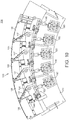
- Figure 11 shows a portion of the apparatus 100 corresponding to one sixth of the full annulus and in particular shows the arrangement of the tool 102 including the body portion 104, five forming elements 106, the continuation portion 128, together with the flange support structure 136 and a portion of the actuation mechanism 138 corresponding to the five flange-forming portions 106 shown.
Landscapes
- Engineering & Computer Science (AREA)
- Chemical & Material Sciences (AREA)
- Composite Materials (AREA)
- Mechanical Engineering (AREA)
- Robotics (AREA)
- Moulding By Coating Moulds (AREA)
- Shaping Of Tube Ends By Bending Or Straightening (AREA)
Description
- The invention relates to a tool for forming a composite component.
- Composite materials are increasingly used for components that require particular combinations of material properties. In particular, composite materials such as Carbon Fibre Reinforced Polymer (CFRP) are commonly used for components in the aerospace and other industries due to their high stiffness and low weight.
- It is frequently desirable to manufacture a component with a flange, such as an annular flange on a casing for a gas turbine, or the sides of a spar for a wing. Where such components are to be manufactured from composite materials, the formation of the flange can pose an engineering problem. For example, it may be difficult to layup composite material on a flanged mould, in particular in the region of bends between the main part of the mould and the flange that may be hard to access.
- One known method of manufacturing a composite component with an integral flange is disclosed in
GB2486231 - However, the circumferentially spaced sectors of
GB2486231 - It is therefore desirable to provide an improved tool for manufacturing a composite component.
- According to a first aspect of the invention there is provided a tool for forming a composite component having a curved body and an integral flange from a pre-form, the tool comprising: a curved body portion having a lay-up surface; and a forming assembly having a lay-up configuration and a forming configuration, the forming assembly comprising: a plurality of forming elements each having a lay-up surface and a primary flange-forming surface, the forming elements being radially outwardly moveable from the lay-up configuration to the forming configuration, in which the forming elements are circumferentially spaced from one another; and a plurality of filler elements each having a secondary flange-forming surface, the filler elements being arranged to move into the circumferential gaps between the forming elements in the forming configuration so as to form a substantially continuous flange-forming surface; wherein in use a pre-form is disposed on the layup surfaces of the curved body portion and the forming elements, and wherein movement to the forming configuration causes the pre-form to be deformed between the continuous flange-forming surface and a counteracting forming surface to form the integral flange.
- In the lay-up configuration, the lay-up surfaces of the forming elements may be substantially continuous with one another and with the lay-up surface of the body portion. The body portion of the tool may be for receiving a first region of a pre-form corresponding to the curved body of the composite component. The forming assembly may be adjacent the curved body portion.
- The lay-up surfaces of the forming elements may be radially spaced apart from the lay-up surface of the body portion in the forming configuration. The lay-up surface of each forming element may be a radially outer surface of the forming element, and the primary flange-forming surface of each forming element may extend radially inwardly from the respective lay-up surface. Each filler element may have a radially outer filler surface arranged to extend into a gap formed between the radially outer lay-up surfaces of the forming elements in the forming configuration to form a substantially continuous outer forming surface. The filler elements may be concealed radially within the forming elements when the forming assembly is in the lay-up configuration.
- The primary and secondary flange-forming surfaces may extend at least partly radially. The primary and secondary forming surfaces may be substantially radially extending (i.e. substantially normal to the axis of the tool).
- The forming elements and the filler elements may be alternately arranged around the axis of the tool. Each pair of adjacent forming and filler elements may have complementary features arranged to engage with each other to axially align the elements relative to each other in the forming configuration.
- Accordingly, each element engages with its adjacent elements in the forming configuration to ensure that the primary and secondary flange-forming surfaces are substantially continuous with each other when the forming assembly is in the forming configuration. The complementary features of each pair of adjacent forming and filler elements are arranged so that the primary and secondary forming surfaces are axially aligned to within a tolerance of 0.25 millimetres in the forming configuration.
- Alternatively, the complementary features of each pair of adjacent forming and filler elements may be arranged so that the primary and secondary forming surfaces are axially aligned to within a tolerance of 0.5 millimetres, or within a tolerance of 0.2 millimetres, or within a tolerance of 0.1 millimetres in the forming configuration.
- The complementary features of each pair of adjacent forming and filler elements may be provided on side surfaces of the respective forming and filler elements. The side surfaces may have both a radial extent and an axial extent.
- The complementary features of each pair of adjacent forming and filler elements may comprise at least one shoulder formed on a first element of the pair and arranged to engage with a corresponding portion of a second element of the pair to limit axial movement of the second element relative the first element along a first axial direction. The complementary features of each pair of adjacent forming and filler elements may comprise at least two shoulders arranged to limit axial movement of the second element relative the first element along two opposing axial directions. The complementary features of each pair of adjacent forming and filler elements may comprise male and female interlocking features. A first element of the pair of elements may comprise a female groove and a second element of the pair of elements may comprise a male projection arranged to be received in the female groove. The groove and projection may extend radially.
- The material composition of the male feature may be different from the material composition of the female feature. In other words, the male and female features may be composed of different materials. The material composition of the male and female features may be different from the material composition of the remainder of the respective forming and filler elements forming the pair. In other words, the male and female features may be composed of a different material to the remainder of the respective forming and filler elements. For example, either one or both of the male and female features may be composed of a material having a different hardness, friction, binding, thermal conduction and/or thermal expansion property than the remainder of the respective elements.
- Each element may comprise a male feature provided on a first side surface of the element for engaging with a corresponding female feature of a first adjacent element, and a female feature provided on an opposing second side surface of the element for engaging with a corresponding male feature of a second adjacent element.
- The complementary features of the forming elements may be configured so that, in the lay-up configuration, the complementary features of the forming elements engage with each other to axially align the forming elements.
- The tool may further comprise a drive means for moving the forming assembly from the lay-up configuration to the forming configuration, the drive means comprising a plurality of drive units, each drive unit being arranged to move at least one forming element; wherein each drive unit is configured to move the or each respective forming element and an adjacent filler element from respective retracted positions corresponding to the lay-up configuration to respective extended positions corresponding to the forming configuration; wherein each drive unit is configured so that the respective filler element reaches its respective forming position after the forming element reaches its respective forming position; and wherein a lost motion connection is provided between each drive unit and the respective forming element. The lost motion connection may comprise a resilient means which biases the forming element away from the drive unit.
- Each drive unit may comprise a guide block, the respective forming element may be guided for displacement with respect to the guide block by means of a guide rod or rail, and the resilient means may comprise a spring which acts between the guide block and the forming element. The guide block may be fixedly secured to the filler element so that the filler element cannot move relative to the guide block.
- The tool may be for forming an annular or semi-annular component. The tool may be for forming a casing for a gas-turbine engine.
- According to a second aspect of the invention here is provided apparatus for forming a composite component having a curved body and an integral curved flange, the apparatus comprising: a tool in accordance with the first aspect of the invention; and a counteracting support detachably attachable to the tool over a pre-form received on the tool, the counteracting support having a counteracting forming surface arranged to oppose the flange-forming surfaces of the forming assembly so that in use a region of the pre-form is deformed between the forming assembly and the counteracting support to form the flange of the component.
- According to a third aspect of the invention there is provided a method of forming a composite component having a curved body and an integral curved flange from a pre-form, the method comprising: providing a pre-form over lay-up surfaces of the curved body portion and the forming elements of an apparatus in accordance with the second aspect of the invention in the lay-up configuration; moving the forming assembly from the lay-up configuration to the forming configuration so that the plurality of forming elements move into gaps between the forming elements in the forming configuration so as to form a substantially continuous flange-forming surface; whereby a region of the pre-form is deformed between the continuous forming surface and the counteracting forming surface to form the integral flange. The method may comprise laying-up the pre-form on the tool.
- The invention will now be described, by way of example, with reference to the accompanying drawings, in which:
-
Figure 1 schematically shows a cutaway view of a gas turbine engine; -
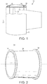
Figure 2 schematically shows the casing of the gas turbine engine ofFigure 1 ; -
Figure 3 schematically shows a partial cross-sectional view of an apparatus for manufacturing a composite component, in which a forming element of the apparatus is shown in a lay-up configuration; -
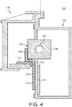
Figure 4 schematically shows a partial cross-sectional view of the apparatus ofFigure 3 in which the forming element has moved relative a body portion of the apparatus; -
Figure 5 schematically shows a partial cross-sectional view the apparatus ofFigures 3 and4 in which the forming element is in the forming configuration; -
Figure 6 schematically shows a radial view of a forming assembly of the apparatus in a lay-up configuration; -
Figure 7 schematically shows a plan view the forming assembly in the lay-up configuration; -
Figure 8 schematically shows a radial view of the forming assembly in a forming configuration; -
Figure 9 schematically shows a plan view of the forming assembly in the forming configuration; -
Figure 10 schematically shows actuation mechanisms for the forming assembly; and -
Figure 11 schematically shows the apparatus ofFigures 3-10 in perspective view. -
Figure 1 shows agas turbine engine 10 comprising anexterior nacelle 12 supported on anannular casing 14 having forward andaft flanges casing 14 is centred on theaxis 20 of theengine 10 and houses afan 22 comprising a plurality of fan blades. Forward and aftannular casing boxes nacelle 12. - As shown in
Figure 2 , thecasing 14 has a curvedmain body 28 which is generally cylindrical and is provided with forward andaft flanges - The
casing 14 is composed of composite material, such as Carbon Fibre Reinforced Polymer (CFRP). In particular, thecasing 14 comprises a plurality of plies of pre-impregnated ("pre-preg") unidirectional composite tape that been have been applied to a mould in a lay-up process and cured. -
Figures 3 to 5 show cross sectional views of anapparatus 100 for manufacturing thecomposite casing 14. - The
apparatus 100 comprises a generallyannular tool 102 that is configured to rest on a horizontal surface, such as a workshop floor, so that its central axis (not shown) extends vertically, although in other embodiments it may be supported in any orientation. Thetool 102 comprises anannular support structure 103 for supporting a formingassembly 105 comprising a plurality of formingelements 106 and filler elements (not shown), and abody portion 104. - The
body portion 104 comprises a plurality of circumferentially extending curved body panels 108 that together define a cylindrical lay-upsurface 110 for acomposite pre-form 200. In this embodiment, there are six curved body panels 108 each having an angular extent of 60º. Thebody portion 104 is provided with abody heater 114 comprising a plurality of heater mats 116 mounted to the radially inner surfaces of the curved body panels 108 for heating the body panels 108, and thereby a pre-form 200 disposed on the outer lay-upsurface 110 of thebody portion 104. In this example, the body panels 108 are composed of a thermally conductive metal, in particular, stainless steel or aluminium. - The forming
assembly 105 is mounted to thesupport structure 103 above thebody portion 104 by an actuation mechanism (not shown) and comprises a plurality of formingelements 106 which are radially movable with respect to thesupport structure 103 and thebody portion 104 between a retracted or lay-up position (for example,Figure 3 ) and an extended or forming position (for example,Figure 5 ). The formingelements 106 are circumferentially arranged around thetool 102. - Each forming
element 106 has a circumferentially extending radially outer lay-upsurface 120 which is configured to be substantially contiguous and continuous with the lay-upsurface 110 of theadjacent body portion 104 in the lay-up configuration of the forming assembly 105 (i.e. with the forming elements in the lay-up position). In the lay-up configuration, the lay-upsurfaces 120 of the formingelements 106 are substantially continuous with each other around the axis of thetool 102. - In the forming configuration, the lay-up
surfaces 120 of the forming elements are radially spaced apart from the lay-upsurface 110 of theadjacent body portion 104, and there are circumferentially extending gaps between them. - The forming
elements 106 are configured so that the lay-upsurfaces 120 of eachelement 120 has a radius of curvature corresponding to the radial position of the lay-upsurface 120 in the forming position. Accordingly, the lay-upsurfaces 120 extend in a true circumferential direction when in the forming position, and extend approximately circumferentially (or substantially circumferentially) in the retracted or lay-up position. - In this example, each forming
element 106 is in the form of a semi-annular block or sector that defines the radially outer lay-upsurface 120 and has four radially extending sides: lower and upper side surfaces 122, 124 and angularly spaced side surfaces (not shown). Thelower side surface 122 acts as a primary flange-forming surface during a forming operation, as will be described in detail below. In this embodiment, each main flange-formingportion 106 has an angular extent of 12º, and so thetool 102 comprises 30 separate main flange-forming portions. - Each main flange-forming
portion 106 comprises acavity 126 in which there is disposed aflange heater 123 for heating the main flange-formingportion 106. Each main flange-formingportion 106 is composed of a thermally conductive metal, in particular, stainless steel or aluminium. Theflange heaters 123 and thebody heater 114 are coupled to a controller (not shown) for controlling flange forming and curing operations, as will be described below. - As shown in
Figures 6-9 , the formingassembly 105 additionally comprises a plurality offiller elements 107. Thefiller elements 107 are in the form of semi-annular blocks configured to move from a radially inner retracted or lay-up position to a radially outer extended or forming position, corresponding to the lay-up and forming configurations of the formingassembly 105 respectively. The blocks have a radiallyouter filler surface 150, annular spaced side surfaces 152, 154, and lower and upper side surfaces 156, 158. Thelower side surface 156 forms a secondary flange-forming surface during a forming operation, as will be described in detail below. - In the lay-up configuration (
Figures 6 and 7 ), thefiller elements 107 are disposed radially inwardly of the lay-up surfaces of the formingelements 106, so that the filler elements are concealed from a radially outer position. The formingelements 106 have tapered angularly spaced side surfaces 160, 162 which, in the lay-up configuration of the forming assembly, define between them a recess for receiving the filler elements 107 (as best shown inFigure 7 ). - In the forming configuration (
Figures 8 and 9 ), thefiller elements 107 extend into the circumferentially extending gaps between the formingelements 106 so that the secondary flange-formingsurface 156 of thefiller elements 107 are substantially continuous with the primary flange-formingsurfaces 122 of the formingelements 106. Additionally, in the forming configuration, the radiallyouter filler surface 150 extends into the circumferentially extending gaps between the lay-upsurfaces 120 of the formingelements 106, so that the lay-upsurfaces 120 andfiller surfaces 150 form a substantially continuous circumferentially extending surface. - As shown in
Figures 7 and 9 , eachfiller element 107 comprises amale projection 164 on itsfirst side surface 152 configured to engage with a correspondingfemale groove 166 formed in asecond side surface 160 of an adjacent formingelement 106. Similarly, eachfiller element 107 comprises afemale groove 168 on itssecond side surface 154 configured to engage with a correspondingmale projection 170 formed in thefirst side surface 162 of an oppositely adjacent formingelement 106. - The
male projections female grooves - In this embodiment, the
male projections female grooves filler elements filler elements - The forming and
filler elements - Referring back to
Figures 3-5 , thetool 102 further comprises a generallycylindrical continuation portion 128 disposed above the formingassembly 105 and having a radially outer lay-up surface 130 arranged to be contiguous and continuous with the lay-upsurfaces 120 of the formingelements 106 in the lay-up configuration. Thecontinuation portion 128 is supported on thesupport structure 103 and comprises a plurality of continuation panels 131. - The lay-up
surfaces body portion 104, formingelements 106 and thecontinuation portion 128 of thetool 102 together define a generally cylindrical continuous lay-upsurface 132 for laying up acylindrical pre-form 200. - The
tool 102 further comprises a plurality ofattachment portions 134 angularly spaced around the circumferential extent of thetool 102 above thecontinuation portion 128 for coupling with aflange support structure 136. Theflange support structure 136 is in the form of an annular frame configured to extend around a pre-form 200 disposed on the lay-upsurface 132 of the tool and is detachably attachable to thetool 102 by cooperatingattachment portions tool 102 and theflange support structure 136 respectively. For example, theattachment portions - The
flange support structure 136 comprises a counteractingflange support portion 137 arranged to counteract the flange-formingsurfaces elements 106 andfiller elements 107 of thetool 102 respectively during a flange forming operation, so as to control the shape of the formed flange. - In particular, the counteracting
flange support portion 137 is arranged to abut a pre-form 200 disposed on the lay-up surface of the tool and defines an annularcounteracting forming surface 140 for shaping the flange region of the component as it is formed in the forming operation. Thecounteracting forming surface 140 is oriented substantially radially (horizontally inFigures 3-5 ) and positioned axially below the level of the flange-formingsurfaces assembly 105 by a distance corresponding to the desired thickness of the flange. Thecounteracting forming surface 140 has a radially inner rounded bend or transition portion for forming a bend or transition region where the flange region and the main body region of the component meet. In this embodiment, the transition portion has a relatively low curvature so that there is a continuous bend between the main body and flange of the composite component. In particular, in this embodiment the flange-forming portion is arranged to form a flange having a radial extent of approximately 65mm, and the radius of curvature for the flange is approximately 10mm. - The
flange support structure 136 also comprises an integral mounting and heating element by which the counteractingflange support portion 137 is mounted and heated for forming and curing. -
Figure 10 shows adrive mechanism 138 for the forming assembly. Thedrive mechanism 138 comprises a plurality of drive units, each having arotary motor 190 for each pair of adjacent forming andfiller elements linear guide rod 192 along a guide direction slightly offset from the radial direction (in other embodiments, the guide direction may be substantially radial). Theguide rod 192 is coupled to aguide block 194 which is fixedly secured to thefiller element 107, and is coupled to the formingelement 106 by acompression spring 196. The guide block is constrained to move along guide rails (not shown) secured to thesupport structure 103. The drive units also include radial stops (not shown) for stopping the radial motion of therespective elements elements 106 andfiller elements 107 from their respective lay-up positions to their respective forming positions. In particular, thecompression spring 196 provides a lost-motion connection between theguide block 194 and the formingelement 106 so that, in use, the formingelement 106 reaches its respective forming position and thefiller element 107 subsequently extends into its forming position between adjacent formingelements 106. -
Figure 11 shows a portion of theapparatus 100 corresponding to one sixth of the full annulus and in particular shows the arrangement of thetool 102 including thebody portion 104, five formingelements 106, thecontinuation portion 128, together with theflange support structure 136 and a portion of theactuation mechanism 138 corresponding to the five flange-formingportions 106 shown. - A method of forming a composite component using the
apparatus 100 will now be described, by way of example, with reference toFigures 3-11 . - The
apparatus 100 is oriented on a support surface, such as a floor, so that its central axis extends vertically. Theapparatus 100 is prepared for a lay-up operation by detaching theflange support structure 132, if attached. Additionally, the actuation mechanism 138 (Figure 10 ) is controlled to return the formingassembly 105 to the lay-up configuration. The formingelements 106 are circumferentially adjacent one another, and themale projection 170 of each formingelement 106 engages with a correspondingfemale groove 166 of it's adjacent forming element, thereby axially aligning the formingelements 106 in the lay-up configuration. - With the forming assembly in the lay-up configuration (
Figures 3 ,6, 7 ) a continuous lay-upsurface 132 is defined on thetool 102 by the radially outer surfaces of thebody portion 104, the forming assembly 105 (the forming elements 106) and thecontinuation portion 128. This lay-upsurface 132 is accessible from a radially outer position. - In this embodiment, a release layer (not shown) is overlaid on the lay-up
surface 132 before the lay-up operation is initiated. - A lay-up operation is conducted in which unidirectional tapes of pre-impregnated composite material are applied over the continuous lay-up
surface 132 in successive layers or plies using an automatic tape laying (ATL) apparatus, thereby forming a substantially cylindricalcomposite pre-form 200 on thetool 102. In this embodiment, the tapes are applied in a combination of ±60º and 90º (i.e. vertical) orientations with respect to a plane normal to the axis of the tool, and extend over the lay-upsurfaces body portion 104 and the formingelements 106. In other example methods, the lay-up operation may be conducted by hand, or using other methods such as Automatic Fibre Placement (AFP) or automatic tape winding. - The composite material is applied to the tool to provide a pre-form having a
body region 206 extending over thebody portion 104 of the tool and aflange region 208 extending over the lay-upsurfaces 120 of the forming elements. In other example methods, theflange region 208 may additionally extend part-way over the lay-up surface 130 of thecontinuation portion 128 of the tool, and/or there may be a continuation region of the pre-form extending from theflange region 208 that may be cut away from the flange after forming or curing. - In this example, the composite material is applied to the tool to provide a pre-form 200 for a casing for a gas turbine having an axial length of 1000mm and a flange radius of 65mm. The composite material is applied to the tool so that the
body region 206 has an axial extent over thebody portion 104 of 1000mm and the flange region has an axial extent over the forming assembly of at least 65mm. - Once the lay-up operation is complete,
adhesive tapes 202 are applied in annular loops to thebody portion 104 andcontinuation portion 128 below and above the pre-form 200 respectively, and avacuum bag 204 is placed over the pre-form 200 and sealed with thetapes 202 against thetool 102. - Vacuum tubes (not shown) are extended through the vacuum bag to the space enclosed between the
tool 102 and thevacuum bag 204, and a vacuum source such as a vacuum pump is applied to the vacuum tubes to create a partial vacuum in the space occupied by the pre-form 200. In this example, a partial vacuum is formed so that an unbalanced pressure force from the ambient atmosphere is applied through the vacuum bag onto the pre-form 200. - The forming operation is initiated by the controller causing the heating apparatus (i.e. the
body heater 114 and flange heaters 123) to heat the pre-form 200 to a threshold forming temperature, which in this example is 80ºC. - When the pre-form 200 has reached the threshold forming temperature, the controller causes the
actuation mechanism 138 to drive the formingelements 106 and the filler elements radially outwardly from the lay-up configuration to the forming configuration (Figures 3-5 and6-9 ). As the formingelements 106 move radially outwardly, circumferential gaps form between them and thefiller elements 107 extend into these gaps. - The
male projections 164 of thefiller portions 107 engage with thefemale grooves 160 of the formingelements 106, and themale projections 170 of the formingelements 106 engage with the correspondingfemale grooves 168 of thefiller elements 107, thereby axially aligning the forming andfiller elements assembly 105 moves to the forming configuration. - As the flange-forming
portions 106 move radially outwardly, theflange region 208 of the pre-form is caused to slide over the lay-upsurface 120 and onto the primary flange-forming surfaces 122 (i.e. the underside of the flange-forming portion 106) and the secondary flange-forming surface 156 (i.e. the underside of the filler portions 107), which together form a substantially continuous flange-forming surface. The movement of the flange-formingportions 106 causes theflange region 208 to plastically deform around and between the flange-formingsurface surface 140 of the counteractingsupport element 137, thereby forming the radial flange of the component. - During the forming operation, the
body region 206 of the pre-form remains substantially in place against thebody portion 104 of thetool 100, held in position by the counteractingsupport element 137. The formingassembly 105 is configured to move slowly during the forming operation, such as at approximately 120mm per hour, to ensure that the layers of thecomposite pre-form 200 are able to move relative one another during the forming operation without creating wrinkles in the pre-form. - Once the flange forming operation is complete (
Figures 5 ,8, 9 ), the controller initiates a curing operation and causes the heating apparatus to heat the pre-form 200, including the formed flange and transition region, to at least a threshold curing temperature, which in this embodiment is 135ºC. The controller also controls the vacuum source so that an unbalanced pressure force is applied to the pre-form through the vacuum bag. - After a curing period of 6 hours, the controller turns off the heaters and the cured
casing 14 is allowed to cool on thetool 102. Theflange support structure 136 is removed from thetool 102 and the vacuum bag and associated equipment is removed from the cured component. Theflange assembly 105 is moved back to the lay-up configuration, and the curedcasing 14 is removed from the tool. - The
casing 14 is then trimmed to remove any continuation portion of the pre-form extending beyond the desired dimensions of the flange. - The invention allows a curved flanged component to be formed from a pre-form by driving forming elements radially outwardly during a forming process, despite the inherent problem that circumferential gaps will form between the forming elements. The filler elements of the forming assembly are configured to move into the respective gaps so as to provide a substantially continuous flange-forming surface. Further, the complementary features of the forming and filler elements improve the axial alignment of the flange-forming surface so that the flange is of the desired shape, such as substantially planar (i.e. radially extending). In particular, there may be a degree of axial play in the actuation mechanism for the forming assembly, which may otherwise affect the axial alignment of the flange-forming surface. For instance, there may be axial play between the filler elements (attached to the guide block) and the guide rails, and/or axial play between the guide block and the forming element, which are coupled by a compression spring. Accordingly, the complementary features of the elements, such as the male and female interlocking projections and grooves, serve to axially align the forming elements during the forming operation and in the forming configuration.
- The expression substantially continuous is intended to mean that there is no step change in the profile of a surface defined across two or more surfaces.
Claims (15)
- A tool (102) for forming a composite component having a curved body (28) and an integral flange (16, 18) from a pre-form (200), the tool (102) comprising:a curved body portion (104) having a lay-up surface (110); anda forming assembly (105) having a lay-up configuration and a forming configuration, the forming assembly (105) comprising:a plurality of forming elements (106) each having a lay-up surface (120) and a primary flange-forming surface (122), the forming elements (106) being radially outwardly moveable from the lay-up configuration to the forming configuration, in which the forming elements (106) are circumferentially spaced from one another;a plurality of filler elements (107) each having a secondary flange-forming surface (156), the filler elements (107) being arranged to move into the circumferential gaps between the forming elements (106) in the forming configuration so as to form a substantially continuous flange-forming surface; andwherein each pair of adjacent forming (106) and filler elements (107) have complementary features (164, 166, 168, 170) arranged to engage with each other to axially align the elements (106, 107) relative to each other in the forming configuration;wherein in use a pre-form (200) can be disposed on the layup surfaces (110, 120) of the curved body portion (104) and the forming elements (106), and wherein movement to the forming configuration causes the pre-form (200) to be deformed between the continuous flange-forming surface and a counteracting forming surface (140) to form the integral flange (16, 18).
- A tool (102) according to claim 1, wherein the primary and secondary flange-forming surfaces (122, 156) extend at least partly radially.
- A tool (102) according to claim 1 or 2, wherein the forming elements (106) and the filler elements (107) are alternately arranged around the axis of the tool (102).
- A tool (102) according to any preceding claim, wherein the complementary features (164, 166, 168, 170) of each pair of adjacent forming and filler elements (106, 107) are arranged so that the primary and secondary forming surfaces (122, 156) are axially aligned to within a tolerance of 0.25 millimetres in the forming configuration.
- A tool (102) according to any preceding claim, wherein the complementary features (164, 166, 168, 170) of each pair of adjacent forming and filler elements (106, 107) are provided on side surfaces of the respective forming and filler elements (106, 107).
- A tool (102) according to any preceding claim, wherein the complementary features (164, 166, 168, 170) of each pair of adjacent forming and filler elements (106, 107) comprises at least one shoulder formed on a first element (106, 107) of the pair and arranged to engage with a corresponding portion of a second element (107, 106) of the pair to limit axial movement of the second element (107, 106) relative the first element (106, 107) along a first axial direction; and
optionally wherein the complementary features (164, 166, 168, 170) of each pair of adjacent forming and filler elements (106, 107) comprise at least two shoulders arranged to limit axial movement of the second element (107, 106) relative the first element (106, 107) along two opposing axial directions. - A tool (102) according to any preceding claim, wherein the complementary features (164, 166, 168, 170) of each pair of adjacent forming and filler elements (106, 107) comprise male (164, 170) and female (166, 168) interlocking features.
- A tool (102) according to claim 7, wherein a first element (106, 107) of the pair of elements comprises a female groove (166, 168) and wherein a second element (107, 106) of the pair of elements comprises a male projection (164, 170) arranged to be received in the female groove (166, 168).
- A tool (102) according to claim 7 or 8, wherein the material composition of the male feature (164, 170) is different from the material composition of the female feature (166, 168); or
wherein the material composition of the male (164, 170) and female features (166, 168) is different from the material composition of the remainder of the respective forming and filler elements (106, 107) forming the pair. - A tool (102) according to any of claims 7 to 9, wherein each element (106, 107) comprises a male feature (164, 170) provided on a first side surface (152, 154) of the element for engaging with a corresponding female feature (166, 168) of a first adjacent element (106, 107), and a female feature (166, 168) provided on an opposing second side surface (154, 152) of the element for engaging with a corresponding male feature (164, 170) of a second adjacent element (107, 106).
- A tool (102) according to any of claims 7 to 10, wherein the complementary features (166, 170) of the forming elements (106) are configured so that, in the lay-up configuration, the complementary features (166, 170) of the forming elements (106) engage with each other to axially align the forming elements (106).
- A tool (102) according to any preceding claim, further comprising a drive means (138) for moving the forming assembly (105) from the lay-up configuration to the forming configuration, the drive means (138) comprising a plurality of drive units, each drive unit being arranged to move at least one forming element (106);
wherein each drive unit is configured to move the or each respective forming element (106) and an adjacent filler element (107) from respective retracted positions corresponding to the lay-up configuration to respective extended positions corresponding to the forming configuration;
wherein each drive unit is configured so that the respective filler element (107) reaches its respective forming position after the forming element (106) reaches its respective forming position; and
wherein a lost motion connection is provided between each drive unit and the respective forming element (106). - A tool (102) according to any preceding claim, wherein the tool (102) is for forming an annular or semi-annular component; and/or
wherein the tool (102) is for forming a casing (14) for a gas-turbine engine. - Apparatus (100) for forming a composite component (14) having a curved body 28) and an integral curved flange (16, 18), the apparatus comprising:a tool (102) in accordance with any of claims 1 to 13; anda counteracting support (137) detachably attachable to the tool (102) over a pre-form (200) received on the tool (102), the counteracting support (137) having a counteracting forming surface (140) arranged to oppose the flange-forming surfaces (122) of the forming assembly (105) so that in use a region of the pre-form (200) is deformed between the forming assembly (105) and the counteracting support (137) to form the flange (16, 18) of the component (14).
- A method of forming a composite component (14) having a curved body (28) and an integral curved flange (16, 18) from a pre-form (200), the method comprising:providing a pre-form (200) over lay-up surfaces (110) of the curved body portion (104) and the forming elements (106) of an apparatus (100) in accordance with claim 14 in the lay-up configuration;moving the forming assembly (105) from the lay-up configuration to the forming configuration so that the plurality of filler elements (107) move into gaps between the forming elements (106) in the forming configuration so as to form a substantially continuous flange-forming surface;whereby a region of the pre-form (200) is deformed between the continuous forming surface and the counteracting forming surface (137) to form the integral flange (16, 18).
Applications Claiming Priority (2)
| Application Number | Priority Date | Filing Date | Title |
|---|---|---|---|
| GBGB1507418.0A GB201507418D0 (en) | 2015-04-30 | 2015-04-30 | A tool for forming a composite component |
| PCT/GB2016/051155 WO2016174400A1 (en) | 2015-04-30 | 2016-04-25 | A tool for forming a composite component |
Publications (2)
| Publication Number | Publication Date |
|---|---|
| EP3288745A1 EP3288745A1 (en) | 2018-03-07 |
| EP3288745B1 true EP3288745B1 (en) | 2019-06-12 |
Family
ID=53488948
Family Applications (1)
| Application Number | Title | Priority Date | Filing Date |
|---|---|---|---|
| EP16718900.0A Active EP3288745B1 (en) | 2015-04-30 | 2016-04-25 | A tool for forming a composite component |
Country Status (7)
| Country | Link |
|---|---|
| US (1) | US10906257B2 (en) |
| EP (1) | EP3288745B1 (en) |
| JP (1) | JP6752228B2 (en) |
| CN (1) | CN107530989B (en) |
| CA (1) | CA2983063A1 (en) |
| GB (1) | GB201507418D0 (en) |
| WO (1) | WO2016174400A1 (en) |
Families Citing this family (3)
| Publication number | Priority date | Publication date | Assignee | Title |
|---|---|---|---|---|
| US10239251B2 (en) | 2016-01-22 | 2019-03-26 | The Boeing Company | Apparatus and method of forming a composite structure |
| ES2958761T3 (en) * | 2019-11-13 | 2024-02-14 | Airbus Operations Slu | Device and method of forming a composite laminate to obtain a Z-shaped profile |
| FR3105070B1 (en) * | 2019-12-19 | 2022-10-14 | Safran Nacelles | Tooling for the manufacture of openwork elements such as grilles for aircraft nacelles and method using such tooling |
Family Cites Families (15)
| Publication number | Priority date | Publication date | Assignee | Title |
|---|---|---|---|---|
| JPS5232388B2 (en) | 1972-11-08 | 1977-08-20 | ||
| JPS63417Y2 (en) | 1981-05-29 | 1988-01-07 | ||
| DE3127203C2 (en) | 1981-07-07 | 1986-01-09 | Günter Hans 1000 Berlin Kiss | Device for folding over the protrusion of a one-sided surface lamination around the edge area of a workpiece |
| JPS6056525U (en) | 1983-09-27 | 1985-04-20 | 住友電気工業株式会社 | Fiber reinforced plastics molding equipment |
| US5356692A (en) * | 1992-07-27 | 1994-10-18 | Lockheed Missiles & Space Company, Inc. | Grid structure with sinuous interstices |
| US5348602A (en) * | 1993-06-08 | 1994-09-20 | General Electric Company | Method for making a bonded laminated article bend portion |
| US6814916B2 (en) | 2002-08-30 | 2004-11-09 | The Boeing Company | Forming method for composites |
| US9102103B2 (en) | 2006-02-02 | 2015-08-11 | The Boeing Company | Thermoplastic composite parts having integrated metal fittings and method of making the same |
| GB2486231B (en) | 2010-12-07 | 2013-04-03 | Gkn Aerospace Services Ltd | Composite structure |
| GB201116476D0 (en) | 2011-09-26 | 2011-11-09 | Rolls Royce Plc | Mandrel for forming a component |
| CN102529108A (en) * | 2011-11-24 | 2012-07-04 | 成都飞机工业(集团)有限责任公司 | Overlaying manufacture method for composite material part |
| FR2991624B1 (en) | 2012-06-12 | 2015-03-06 | Airbus Operations Sas | METHOD FOR MAKING A CURVED PROFILE OF COMPOSITE MATERIAL FROM A RECTILINE PREFORM OF FIBER PATCHES |
| US8535042B1 (en) | 2012-09-14 | 2013-09-17 | General Electric Company | Apparatus for manufacturing a flanged component and methods of manufacturing the same |
| GB201507412D0 (en) | 2015-04-30 | 2015-06-17 | Composite Technology & Applic Ltd | A method and Apparatus for Forming a Composite Component |
| US10328611B2 (en) * | 2015-10-09 | 2019-06-25 | The Boeing Company | Mechanical support tooling and/or mandrel for composite part curing |
-
2015
- 2015-04-30 GB GBGB1507418.0A patent/GB201507418D0/en not_active Ceased
-
2016
- 2016-04-25 US US15/568,346 patent/US10906257B2/en active Active
- 2016-04-25 JP JP2017556715A patent/JP6752228B2/en active Active
- 2016-04-25 CA CA2983063A patent/CA2983063A1/en not_active Abandoned
- 2016-04-25 WO PCT/GB2016/051155 patent/WO2016174400A1/en not_active Ceased
- 2016-04-25 CN CN201680024736.XA patent/CN107530989B/en active Active
- 2016-04-25 EP EP16718900.0A patent/EP3288745B1/en active Active
Non-Patent Citations (1)
| Title |
|---|
| None * |
Also Published As
| Publication number | Publication date |
|---|---|
| JP6752228B2 (en) | 2020-09-09 |
| GB201507418D0 (en) | 2015-06-17 |
| US10906257B2 (en) | 2021-02-02 |
| US20180141289A1 (en) | 2018-05-24 |
| JP2018515365A (en) | 2018-06-14 |
| CN107530989A (en) | 2018-01-02 |
| CA2983063A1 (en) | 2016-11-03 |
| EP3288745A1 (en) | 2018-03-07 |
| CN107530989B (en) | 2020-07-14 |
| WO2016174400A1 (en) | 2016-11-03 |
Similar Documents
| Publication | Publication Date | Title |
|---|---|---|
| EP3288746B1 (en) | A method and apparatus for forming a composite component | |
| US11999079B2 (en) | Method for manufacturing a composite component | |
| EP3288747B1 (en) | A method of manufacturing a composite component | |
| US10906257B2 (en) | Tool for forming a composite component | |
| EP2682245B1 (en) | Apparatus for manufacturing a flanged composite component and methods of manufacturing the same | |
| US10226915B1 (en) | Systems of forming a skin for a composite structure | |
| JP2018521873A5 (en) | ||
| KR20130105873A (en) | Molding die | |
| JP2018515365A5 (en) | ||
| EP3113935B1 (en) | Self-heating tool and method of manufacturing a composite component using the same | |
| GB2555833A (en) | A tool and method for forming a composite component |
Legal Events
| Date | Code | Title | Description |
|---|---|---|---|
| STAA | Information on the status of an ep patent application or granted ep patent |
Free format text: STATUS: THE INTERNATIONAL PUBLICATION HAS BEEN MADE |
|
| PUAI | Public reference made under article 153(3) epc to a published international application that has entered the european phase |
Free format text: ORIGINAL CODE: 0009012 |
|
| STAA | Information on the status of an ep patent application or granted ep patent |
Free format text: STATUS: REQUEST FOR EXAMINATION WAS MADE |
|
| 17P | Request for examination filed |
Effective date: 20171129 |
|
| AK | Designated contracting states |
Kind code of ref document: A1 Designated state(s): AL AT BE BG CH CY CZ DE DK EE ES FI FR GB GR HR HU IE IS IT LI LT LU LV MC MK MT NL NO PL PT RO RS SE SI SK SM TR |
|
| AX | Request for extension of the european patent |
Extension state: BA ME |
|
| DAV | Request for validation of the european patent (deleted) | ||
| DAX | Request for extension of the european patent (deleted) | ||
| RIC1 | Information provided on ipc code assigned before grant |
Ipc: B29C 33/30 20060101ALI20181106BHEP Ipc: B29C 70/46 20060101AFI20181106BHEP Ipc: B29C 70/38 20060101ALI20181106BHEP Ipc: B29C 70/56 20060101ALI20181106BHEP Ipc: B29C 70/76 20060101ALI20181106BHEP |
|
| GRAP | Despatch of communication of intention to grant a patent |
Free format text: ORIGINAL CODE: EPIDOSNIGR1 |
|
| STAA | Information on the status of an ep patent application or granted ep patent |
Free format text: STATUS: GRANT OF PATENT IS INTENDED |
|
| INTG | Intention to grant announced |
Effective date: 20181217 |
|
| GRAJ | Information related to disapproval of communication of intention to grant by the applicant or resumption of examination proceedings by the epo deleted |
Free format text: ORIGINAL CODE: EPIDOSDIGR1 |
|
| STAA | Information on the status of an ep patent application or granted ep patent |
Free format text: STATUS: REQUEST FOR EXAMINATION WAS MADE |
|
| RAP1 | Party data changed (applicant data changed or rights of an application transferred) |
Owner name: ROLLS-ROYCE PLC |
|
| GRAR | Information related to intention to grant a patent recorded |
Free format text: ORIGINAL CODE: EPIDOSNIGR71 |
|
| GRAS | Grant fee paid |
Free format text: ORIGINAL CODE: EPIDOSNIGR3 |
|
| STAA | Information on the status of an ep patent application or granted ep patent |
Free format text: STATUS: GRANT OF PATENT IS INTENDED |
|
| GRAA | (expected) grant |
Free format text: ORIGINAL CODE: 0009210 |
|
| STAA | Information on the status of an ep patent application or granted ep patent |
Free format text: STATUS: THE PATENT HAS BEEN GRANTED |
|
| INTC | Intention to grant announced (deleted) | ||
| AK | Designated contracting states |
Kind code of ref document: B1 Designated state(s): AL AT BE BG CH CY CZ DE DK EE ES FI FR GB GR HR HU IE IS IT LI LT LU LV MC MK MT NL NO PL PT RO RS SE SI SK SM TR |
|
| INTG | Intention to grant announced |
Effective date: 20190507 |
|
| REG | Reference to a national code |
Ref country code: GB Ref legal event code: FG4D |
|
| REG | Reference to a national code |
Ref country code: CH Ref legal event code: EP |
|
| REG | Reference to a national code |
Ref country code: AT Ref legal event code: REF Ref document number: 1142027 Country of ref document: AT Kind code of ref document: T Effective date: 20190615 |
|
| REG | Reference to a national code |
Ref country code: DE Ref legal event code: R096 Ref document number: 602016015185 Country of ref document: DE |
|
| REG | Reference to a national code |
Ref country code: IE Ref legal event code: FG4D |
|
| REG | Reference to a national code |
Ref country code: NL Ref legal event code: MP Effective date: 20190612 |
|
| REG | Reference to a national code |
Ref country code: LT Ref legal event code: MG4D |
|
| PG25 | Lapsed in a contracting state [announced via postgrant information from national office to epo] |
Ref country code: LT Free format text: LAPSE BECAUSE OF FAILURE TO SUBMIT A TRANSLATION OF THE DESCRIPTION OR TO PAY THE FEE WITHIN THE PRESCRIBED TIME-LIMIT Effective date: 20190612 Ref country code: HR Free format text: LAPSE BECAUSE OF FAILURE TO SUBMIT A TRANSLATION OF THE DESCRIPTION OR TO PAY THE FEE WITHIN THE PRESCRIBED TIME-LIMIT Effective date: 20190612 Ref country code: FI Free format text: LAPSE BECAUSE OF FAILURE TO SUBMIT A TRANSLATION OF THE DESCRIPTION OR TO PAY THE FEE WITHIN THE PRESCRIBED TIME-LIMIT Effective date: 20190612 Ref country code: AL Free format text: LAPSE BECAUSE OF FAILURE TO SUBMIT A TRANSLATION OF THE DESCRIPTION OR TO PAY THE FEE WITHIN THE PRESCRIBED TIME-LIMIT Effective date: 20190612 Ref country code: NO Free format text: LAPSE BECAUSE OF FAILURE TO SUBMIT A TRANSLATION OF THE DESCRIPTION OR TO PAY THE FEE WITHIN THE PRESCRIBED TIME-LIMIT Effective date: 20190912 Ref country code: SE Free format text: LAPSE BECAUSE OF FAILURE TO SUBMIT A TRANSLATION OF THE DESCRIPTION OR TO PAY THE FEE WITHIN THE PRESCRIBED TIME-LIMIT Effective date: 20190612 |
|
| PG25 | Lapsed in a contracting state [announced via postgrant information from national office to epo] |
Ref country code: RS Free format text: LAPSE BECAUSE OF FAILURE TO SUBMIT A TRANSLATION OF THE DESCRIPTION OR TO PAY THE FEE WITHIN THE PRESCRIBED TIME-LIMIT Effective date: 20190612 Ref country code: BG Free format text: LAPSE BECAUSE OF FAILURE TO SUBMIT A TRANSLATION OF THE DESCRIPTION OR TO PAY THE FEE WITHIN THE PRESCRIBED TIME-LIMIT Effective date: 20190912 Ref country code: LV Free format text: LAPSE BECAUSE OF FAILURE TO SUBMIT A TRANSLATION OF THE DESCRIPTION OR TO PAY THE FEE WITHIN THE PRESCRIBED TIME-LIMIT Effective date: 20190612 Ref country code: GR Free format text: LAPSE BECAUSE OF FAILURE TO SUBMIT A TRANSLATION OF THE DESCRIPTION OR TO PAY THE FEE WITHIN THE PRESCRIBED TIME-LIMIT Effective date: 20190913 |
|
| REG | Reference to a national code |
Ref country code: AT Ref legal event code: MK05 Ref document number: 1142027 Country of ref document: AT Kind code of ref document: T Effective date: 20190612 |
|
| PG25 | Lapsed in a contracting state [announced via postgrant information from national office to epo] |
Ref country code: EE Free format text: LAPSE BECAUSE OF FAILURE TO SUBMIT A TRANSLATION OF THE DESCRIPTION OR TO PAY THE FEE WITHIN THE PRESCRIBED TIME-LIMIT Effective date: 20190612 Ref country code: SK Free format text: LAPSE BECAUSE OF FAILURE TO SUBMIT A TRANSLATION OF THE DESCRIPTION OR TO PAY THE FEE WITHIN THE PRESCRIBED TIME-LIMIT Effective date: 20190612 Ref country code: AT Free format text: LAPSE BECAUSE OF FAILURE TO SUBMIT A TRANSLATION OF THE DESCRIPTION OR TO PAY THE FEE WITHIN THE PRESCRIBED TIME-LIMIT Effective date: 20190612 Ref country code: PT Free format text: LAPSE BECAUSE OF FAILURE TO SUBMIT A TRANSLATION OF THE DESCRIPTION OR TO PAY THE FEE WITHIN THE PRESCRIBED TIME-LIMIT Effective date: 20191014 Ref country code: RO Free format text: LAPSE BECAUSE OF FAILURE TO SUBMIT A TRANSLATION OF THE DESCRIPTION OR TO PAY THE FEE WITHIN THE PRESCRIBED TIME-LIMIT Effective date: 20190612 Ref country code: CZ Free format text: LAPSE BECAUSE OF FAILURE TO SUBMIT A TRANSLATION OF THE DESCRIPTION OR TO PAY THE FEE WITHIN THE PRESCRIBED TIME-LIMIT Effective date: 20190612 Ref country code: NL Free format text: LAPSE BECAUSE OF FAILURE TO SUBMIT A TRANSLATION OF THE DESCRIPTION OR TO PAY THE FEE WITHIN THE PRESCRIBED TIME-LIMIT Effective date: 20190612 |
|
| RAP2 | Party data changed (patent owner data changed or rights of a patent transferred) |
Owner name: ROLLS-ROYCE PLC |
|
| PG25 | Lapsed in a contracting state [announced via postgrant information from national office to epo] |
Ref country code: SM Free format text: LAPSE BECAUSE OF FAILURE TO SUBMIT A TRANSLATION OF THE DESCRIPTION OR TO PAY THE FEE WITHIN THE PRESCRIBED TIME-LIMIT Effective date: 20190612 Ref country code: IS Free format text: LAPSE BECAUSE OF FAILURE TO SUBMIT A TRANSLATION OF THE DESCRIPTION OR TO PAY THE FEE WITHIN THE PRESCRIBED TIME-LIMIT Effective date: 20191012 Ref country code: ES Free format text: LAPSE BECAUSE OF FAILURE TO SUBMIT A TRANSLATION OF THE DESCRIPTION OR TO PAY THE FEE WITHIN THE PRESCRIBED TIME-LIMIT Effective date: 20190612 Ref country code: IT Free format text: LAPSE BECAUSE OF FAILURE TO SUBMIT A TRANSLATION OF THE DESCRIPTION OR TO PAY THE FEE WITHIN THE PRESCRIBED TIME-LIMIT Effective date: 20190612 |
|
| REG | Reference to a national code |
Ref country code: DE Ref legal event code: R097 Ref document number: 602016015185 Country of ref document: DE |
|
| PG25 | Lapsed in a contracting state [announced via postgrant information from national office to epo] |
Ref country code: TR Free format text: LAPSE BECAUSE OF FAILURE TO SUBMIT A TRANSLATION OF THE DESCRIPTION OR TO PAY THE FEE WITHIN THE PRESCRIBED TIME-LIMIT Effective date: 20190612 |
|
| PLBE | No opposition filed within time limit |
Free format text: ORIGINAL CODE: 0009261 |
|
| STAA | Information on the status of an ep patent application or granted ep patent |
Free format text: STATUS: NO OPPOSITION FILED WITHIN TIME LIMIT |
|
| PG25 | Lapsed in a contracting state [announced via postgrant information from national office to epo] |
Ref country code: PL Free format text: LAPSE BECAUSE OF FAILURE TO SUBMIT A TRANSLATION OF THE DESCRIPTION OR TO PAY THE FEE WITHIN THE PRESCRIBED TIME-LIMIT Effective date: 20190612 Ref country code: DK Free format text: LAPSE BECAUSE OF FAILURE TO SUBMIT A TRANSLATION OF THE DESCRIPTION OR TO PAY THE FEE WITHIN THE PRESCRIBED TIME-LIMIT Effective date: 20190612 |
|
| 26N | No opposition filed |
Effective date: 20200313 |
|
| PG25 | Lapsed in a contracting state [announced via postgrant information from national office to epo] |
Ref country code: IS Free format text: LAPSE BECAUSE OF FAILURE TO SUBMIT A TRANSLATION OF THE DESCRIPTION OR TO PAY THE FEE WITHIN THE PRESCRIBED TIME-LIMIT Effective date: 20200224 Ref country code: SI Free format text: LAPSE BECAUSE OF FAILURE TO SUBMIT A TRANSLATION OF THE DESCRIPTION OR TO PAY THE FEE WITHIN THE PRESCRIBED TIME-LIMIT Effective date: 20190612 |
|
| PG2D | Information on lapse in contracting state deleted |
Ref country code: IS |
|
| PG25 | Lapsed in a contracting state [announced via postgrant information from national office to epo] |
Ref country code: MC Free format text: LAPSE BECAUSE OF FAILURE TO SUBMIT A TRANSLATION OF THE DESCRIPTION OR TO PAY THE FEE WITHIN THE PRESCRIBED TIME-LIMIT Effective date: 20190612 |
|
| REG | Reference to a national code |
Ref country code: CH Ref legal event code: PL |
|
| REG | Reference to a national code |
Ref country code: DE Ref legal event code: R082 Ref document number: 602016015185 Country of ref document: DE Representative=s name: HL KEMPNER PATENTANWAELTE, SOLICITORS (ENGLAND, DE Ref country code: DE Ref legal event code: R082 Ref document number: 602016015185 Country of ref document: DE Representative=s name: HL KEMPNER PATENTANWALT, RECHTSANWALT, SOLICIT, DE Ref country code: DE Ref legal event code: R082 Ref document number: 602016015185 Country of ref document: DE Representative=s name: HL KEMPNER PARTG MBB, DE |
|
| PG25 | Lapsed in a contracting state [announced via postgrant information from national office to epo] |
Ref country code: CH Free format text: LAPSE BECAUSE OF NON-PAYMENT OF DUE FEES Effective date: 20200430 Ref country code: LU Free format text: LAPSE BECAUSE OF NON-PAYMENT OF DUE FEES Effective date: 20200425 Ref country code: LI Free format text: LAPSE BECAUSE OF NON-PAYMENT OF DUE FEES Effective date: 20200430 |
|
| REG | Reference to a national code |
Ref country code: BE Ref legal event code: MM Effective date: 20200430 |
|
| PG25 | Lapsed in a contracting state [announced via postgrant information from national office to epo] |
Ref country code: BE Free format text: LAPSE BECAUSE OF NON-PAYMENT OF DUE FEES Effective date: 20200430 |
|
| PG25 | Lapsed in a contracting state [announced via postgrant information from national office to epo] |
Ref country code: IE Free format text: LAPSE BECAUSE OF NON-PAYMENT OF DUE FEES Effective date: 20200425 |
|
| PG25 | Lapsed in a contracting state [announced via postgrant information from national office to epo] |
Ref country code: MT Free format text: LAPSE BECAUSE OF FAILURE TO SUBMIT A TRANSLATION OF THE DESCRIPTION OR TO PAY THE FEE WITHIN THE PRESCRIBED TIME-LIMIT Effective date: 20190612 Ref country code: CY Free format text: LAPSE BECAUSE OF FAILURE TO SUBMIT A TRANSLATION OF THE DESCRIPTION OR TO PAY THE FEE WITHIN THE PRESCRIBED TIME-LIMIT Effective date: 20190612 |
|
| PG25 | Lapsed in a contracting state [announced via postgrant information from national office to epo] |
Ref country code: MK Free format text: LAPSE BECAUSE OF FAILURE TO SUBMIT A TRANSLATION OF THE DESCRIPTION OR TO PAY THE FEE WITHIN THE PRESCRIBED TIME-LIMIT Effective date: 20190612 |
|
| P01 | Opt-out of the competence of the unified patent court (upc) registered |
Effective date: 20230528 |
|
| PGFP | Annual fee paid to national office [announced via postgrant information from national office to epo] |
Ref country code: GB Payment date: 20260313 Year of fee payment: 11 |
|
| PGFP | Annual fee paid to national office [announced via postgrant information from national office to epo] |
Ref country code: DE Payment date: 20260421 Year of fee payment: 11 |
|
| PGFP | Annual fee paid to national office [announced via postgrant information from national office to epo] |
Ref country code: FR Payment date: 20260423 Year of fee payment: 11 |