EP3288503B1 - Fussprothese - Google Patents
Fussprothese Download PDFInfo
- Publication number
- EP3288503B1 EP3288503B1 EP16718708.7A EP16718708A EP3288503B1 EP 3288503 B1 EP3288503 B1 EP 3288503B1 EP 16718708 A EP16718708 A EP 16718708A EP 3288503 B1 EP3288503 B1 EP 3288503B1
- Authority
- EP
- European Patent Office
- Prior art keywords
- foot
- hydraulic cylinder
- foot part
- neutral position
- movement
- Prior art date
- Legal status (The legal status is an assumption and is not a legal conclusion. Google has not performed a legal analysis and makes no representation as to the accuracy of the status listed.)
- Active
Links
Images





Classifications
-
- A—HUMAN NECESSITIES
- A61—MEDICAL OR VETERINARY SCIENCE; HYGIENE
- A61F—FILTERS IMPLANTABLE INTO BLOOD VESSELS; PROSTHESES; DEVICES PROVIDING PATENCY TO, OR PREVENTING COLLAPSING OF, TUBULAR STRUCTURES OF THE BODY, e.g. STENTS; ORTHOPAEDIC, NURSING OR CONTRACEPTIVE DEVICES; FOMENTATION; TREATMENT OR PROTECTION OF EYES OR EARS; BANDAGES, DRESSINGS OR ABSORBENT PADS; FIRST-AID KITS
- A61F2/00—Filters implantable into blood vessels; Prostheses, i.e. artificial substitutes or replacements for parts of the body; Appliances for connecting them with the body; Devices providing patency to, or preventing collapsing of, tubular structures of the body, e.g. stents
- A61F2/50—Prostheses not implantable in the body
- A61F2/60—Artificial legs or feet or parts thereof
- A61F2/66—Feet; Ankle joints
-
- A—HUMAN NECESSITIES
- A61—MEDICAL OR VETERINARY SCIENCE; HYGIENE
- A61B—DIAGNOSIS; SURGERY; IDENTIFICATION
- A61B5/00—Measuring for diagnostic purposes; Identification of persons
- A61B5/103—Measuring devices for testing the shape, pattern, colour, size or movement of the body or parts thereof, for diagnostic purposes
- A61B5/1036—Measuring load distribution, e.g. podologic studies
- A61B5/1038—Measuring plantar pressure during gait
-
- A—HUMAN NECESSITIES
- A61—MEDICAL OR VETERINARY SCIENCE; HYGIENE
- A61B—DIAGNOSIS; SURGERY; IDENTIFICATION
- A61B5/00—Measuring for diagnostic purposes; Identification of persons
- A61B5/103—Measuring devices for testing the shape, pattern, colour, size or movement of the body or parts thereof, for diagnostic purposes
- A61B5/11—Measuring movement of the entire body or parts thereof, e.g. head or hand tremor or mobility of a limb
- A61B5/112—Gait analysis
-
- A—HUMAN NECESSITIES
- A61—MEDICAL OR VETERINARY SCIENCE; HYGIENE
- A61F—FILTERS IMPLANTABLE INTO BLOOD VESSELS; PROSTHESES; DEVICES PROVIDING PATENCY TO, OR PREVENTING COLLAPSING OF, TUBULAR STRUCTURES OF THE BODY, e.g. STENTS; ORTHOPAEDIC, NURSING OR CONTRACEPTIVE DEVICES; FOMENTATION; TREATMENT OR PROTECTION OF EYES OR EARS; BANDAGES, DRESSINGS OR ABSORBENT PADS; FIRST-AID KITS
- A61F2/00—Filters implantable into blood vessels; Prostheses, i.e. artificial substitutes or replacements for parts of the body; Appliances for connecting them with the body; Devices providing patency to, or preventing collapsing of, tubular structures of the body, e.g. stents
- A61F2/50—Prostheses not implantable in the body
- A61F2/60—Artificial legs or feet or parts thereof
- A61F2/66—Feet; Ankle joints
- A61F2/6607—Ankle joints
-
- A—HUMAN NECESSITIES
- A61—MEDICAL OR VETERINARY SCIENCE; HYGIENE
- A61F—FILTERS IMPLANTABLE INTO BLOOD VESSELS; PROSTHESES; DEVICES PROVIDING PATENCY TO, OR PREVENTING COLLAPSING OF, TUBULAR STRUCTURES OF THE BODY, e.g. STENTS; ORTHOPAEDIC, NURSING OR CONTRACEPTIVE DEVICES; FOMENTATION; TREATMENT OR PROTECTION OF EYES OR EARS; BANDAGES, DRESSINGS OR ABSORBENT PADS; FIRST-AID KITS
- A61F2/00—Filters implantable into blood vessels; Prostheses, i.e. artificial substitutes or replacements for parts of the body; Appliances for connecting them with the body; Devices providing patency to, or preventing collapsing of, tubular structures of the body, e.g. stents
- A61F2/50—Prostheses not implantable in the body
- A61F2/68—Operating or control means
- A61F2/74—Operating or control means fluid, i.e. hydraulic or pneumatic
-
- A—HUMAN NECESSITIES
- A61—MEDICAL OR VETERINARY SCIENCE; HYGIENE
- A61F—FILTERS IMPLANTABLE INTO BLOOD VESSELS; PROSTHESES; DEVICES PROVIDING PATENCY TO, OR PREVENTING COLLAPSING OF, TUBULAR STRUCTURES OF THE BODY, e.g. STENTS; ORTHOPAEDIC, NURSING OR CONTRACEPTIVE DEVICES; FOMENTATION; TREATMENT OR PROTECTION OF EYES OR EARS; BANDAGES, DRESSINGS OR ABSORBENT PADS; FIRST-AID KITS
- A61F2/00—Filters implantable into blood vessels; Prostheses, i.e. artificial substitutes or replacements for parts of the body; Appliances for connecting them with the body; Devices providing patency to, or preventing collapsing of, tubular structures of the body, e.g. stents
- A61F2/50—Prostheses not implantable in the body
- A61F2/68—Operating or control means
- A61F2/74—Operating or control means fluid, i.e. hydraulic or pneumatic
- A61F2/748—Valve systems
-
- A—HUMAN NECESSITIES
- A61—MEDICAL OR VETERINARY SCIENCE; HYGIENE
- A61F—FILTERS IMPLANTABLE INTO BLOOD VESSELS; PROSTHESES; DEVICES PROVIDING PATENCY TO, OR PREVENTING COLLAPSING OF, TUBULAR STRUCTURES OF THE BODY, e.g. STENTS; ORTHOPAEDIC, NURSING OR CONTRACEPTIVE DEVICES; FOMENTATION; TREATMENT OR PROTECTION OF EYES OR EARS; BANDAGES, DRESSINGS OR ABSORBENT PADS; FIRST-AID KITS
- A61F2/00—Filters implantable into blood vessels; Prostheses, i.e. artificial substitutes or replacements for parts of the body; Appliances for connecting them with the body; Devices providing patency to, or preventing collapsing of, tubular structures of the body, e.g. stents
- A61F2/50—Prostheses not implantable in the body
- A61F2/76—Means for assembling, fitting or testing prostheses, e.g. for measuring or balancing, e.g. alignment means
-
- A—HUMAN NECESSITIES
- A61—MEDICAL OR VETERINARY SCIENCE; HYGIENE
- A61F—FILTERS IMPLANTABLE INTO BLOOD VESSELS; PROSTHESES; DEVICES PROVIDING PATENCY TO, OR PREVENTING COLLAPSING OF, TUBULAR STRUCTURES OF THE BODY, e.g. STENTS; ORTHOPAEDIC, NURSING OR CONTRACEPTIVE DEVICES; FOMENTATION; TREATMENT OR PROTECTION OF EYES OR EARS; BANDAGES, DRESSINGS OR ABSORBENT PADS; FIRST-AID KITS
- A61F2/00—Filters implantable into blood vessels; Prostheses, i.e. artificial substitutes or replacements for parts of the body; Appliances for connecting them with the body; Devices providing patency to, or preventing collapsing of, tubular structures of the body, e.g. stents
- A61F2/50—Prostheses not implantable in the body
- A61F2/5044—Designing or manufacturing processes
-
- A—HUMAN NECESSITIES
- A61—MEDICAL OR VETERINARY SCIENCE; HYGIENE
- A61F—FILTERS IMPLANTABLE INTO BLOOD VESSELS; PROSTHESES; DEVICES PROVIDING PATENCY TO, OR PREVENTING COLLAPSING OF, TUBULAR STRUCTURES OF THE BODY, e.g. STENTS; ORTHOPAEDIC, NURSING OR CONTRACEPTIVE DEVICES; FOMENTATION; TREATMENT OR PROTECTION OF EYES OR EARS; BANDAGES, DRESSINGS OR ABSORBENT PADS; FIRST-AID KITS
- A61F2/00—Filters implantable into blood vessels; Prostheses, i.e. artificial substitutes or replacements for parts of the body; Appliances for connecting them with the body; Devices providing patency to, or preventing collapsing of, tubular structures of the body, e.g. stents
- A61F2/50—Prostheses not implantable in the body
- A61F2002/5003—Prostheses not implantable in the body having damping means, e.g. shock absorbers
-
- A—HUMAN NECESSITIES
- A61—MEDICAL OR VETERINARY SCIENCE; HYGIENE
- A61F—FILTERS IMPLANTABLE INTO BLOOD VESSELS; PROSTHESES; DEVICES PROVIDING PATENCY TO, OR PREVENTING COLLAPSING OF, TUBULAR STRUCTURES OF THE BODY, e.g. STENTS; ORTHOPAEDIC, NURSING OR CONTRACEPTIVE DEVICES; FOMENTATION; TREATMENT OR PROTECTION OF EYES OR EARS; BANDAGES, DRESSINGS OR ABSORBENT PADS; FIRST-AID KITS
- A61F2/00—Filters implantable into blood vessels; Prostheses, i.e. artificial substitutes or replacements for parts of the body; Appliances for connecting them with the body; Devices providing patency to, or preventing collapsing of, tubular structures of the body, e.g. stents
- A61F2/50—Prostheses not implantable in the body
- A61F2002/5003—Prostheses not implantable in the body having damping means, e.g. shock absorbers
- A61F2002/5006—Dampers, e.g. hydraulic damper
-
- A—HUMAN NECESSITIES
- A61—MEDICAL OR VETERINARY SCIENCE; HYGIENE
- A61F—FILTERS IMPLANTABLE INTO BLOOD VESSELS; PROSTHESES; DEVICES PROVIDING PATENCY TO, OR PREVENTING COLLAPSING OF, TUBULAR STRUCTURES OF THE BODY, e.g. STENTS; ORTHOPAEDIC, NURSING OR CONTRACEPTIVE DEVICES; FOMENTATION; TREATMENT OR PROTECTION OF EYES OR EARS; BANDAGES, DRESSINGS OR ABSORBENT PADS; FIRST-AID KITS
- A61F2/00—Filters implantable into blood vessels; Prostheses, i.e. artificial substitutes or replacements for parts of the body; Appliances for connecting them with the body; Devices providing patency to, or preventing collapsing of, tubular structures of the body, e.g. stents
- A61F2/50—Prostheses not implantable in the body
- A61F2002/5016—Prostheses not implantable in the body adjustable
- A61F2002/503—Prostheses not implantable in the body adjustable for adjusting elasticity, flexibility, spring rate or mechanical tension
-
- A—HUMAN NECESSITIES
- A61—MEDICAL OR VETERINARY SCIENCE; HYGIENE
- A61F—FILTERS IMPLANTABLE INTO BLOOD VESSELS; PROSTHESES; DEVICES PROVIDING PATENCY TO, OR PREVENTING COLLAPSING OF, TUBULAR STRUCTURES OF THE BODY, e.g. STENTS; ORTHOPAEDIC, NURSING OR CONTRACEPTIVE DEVICES; FOMENTATION; TREATMENT OR PROTECTION OF EYES OR EARS; BANDAGES, DRESSINGS OR ABSORBENT PADS; FIRST-AID KITS
- A61F2/00—Filters implantable into blood vessels; Prostheses, i.e. artificial substitutes or replacements for parts of the body; Appliances for connecting them with the body; Devices providing patency to, or preventing collapsing of, tubular structures of the body, e.g. stents
- A61F2/50—Prostheses not implantable in the body
- A61F2/60—Artificial legs or feet or parts thereof
- A61F2002/607—Lower legs
-
- A—HUMAN NECESSITIES
- A61—MEDICAL OR VETERINARY SCIENCE; HYGIENE
- A61F—FILTERS IMPLANTABLE INTO BLOOD VESSELS; PROSTHESES; DEVICES PROVIDING PATENCY TO, OR PREVENTING COLLAPSING OF, TUBULAR STRUCTURES OF THE BODY, e.g. STENTS; ORTHOPAEDIC, NURSING OR CONTRACEPTIVE DEVICES; FOMENTATION; TREATMENT OR PROTECTION OF EYES OR EARS; BANDAGES, DRESSINGS OR ABSORBENT PADS; FIRST-AID KITS
- A61F2/00—Filters implantable into blood vessels; Prostheses, i.e. artificial substitutes or replacements for parts of the body; Appliances for connecting them with the body; Devices providing patency to, or preventing collapsing of, tubular structures of the body, e.g. stents
- A61F2/50—Prostheses not implantable in the body
- A61F2/60—Artificial legs or feet or parts thereof
- A61F2/66—Feet; Ankle joints
- A61F2002/6614—Feet
- A61F2002/6657—Feet having a plate-like or strip-like spring element, e.g. an energy-storing cantilever spring keel
-
- A—HUMAN NECESSITIES
- A61—MEDICAL OR VETERINARY SCIENCE; HYGIENE
- A61F—FILTERS IMPLANTABLE INTO BLOOD VESSELS; PROSTHESES; DEVICES PROVIDING PATENCY TO, OR PREVENTING COLLAPSING OF, TUBULAR STRUCTURES OF THE BODY, e.g. STENTS; ORTHOPAEDIC, NURSING OR CONTRACEPTIVE DEVICES; FOMENTATION; TREATMENT OR PROTECTION OF EYES OR EARS; BANDAGES, DRESSINGS OR ABSORBENT PADS; FIRST-AID KITS
- A61F2/00—Filters implantable into blood vessels; Prostheses, i.e. artificial substitutes or replacements for parts of the body; Appliances for connecting them with the body; Devices providing patency to, or preventing collapsing of, tubular structures of the body, e.g. stents
- A61F2/50—Prostheses not implantable in the body
- A61F2/68—Operating or control means
- A61F2002/6818—Operating or control means for braking
-
- A—HUMAN NECESSITIES
- A61—MEDICAL OR VETERINARY SCIENCE; HYGIENE
- A61F—FILTERS IMPLANTABLE INTO BLOOD VESSELS; PROSTHESES; DEVICES PROVIDING PATENCY TO, OR PREVENTING COLLAPSING OF, TUBULAR STRUCTURES OF THE BODY, e.g. STENTS; ORTHOPAEDIC, NURSING OR CONTRACEPTIVE DEVICES; FOMENTATION; TREATMENT OR PROTECTION OF EYES OR EARS; BANDAGES, DRESSINGS OR ABSORBENT PADS; FIRST-AID KITS
- A61F2/00—Filters implantable into blood vessels; Prostheses, i.e. artificial substitutes or replacements for parts of the body; Appliances for connecting them with the body; Devices providing patency to, or preventing collapsing of, tubular structures of the body, e.g. stents
- A61F2/50—Prostheses not implantable in the body
- A61F2/68—Operating or control means
- A61F2002/6845—Clutches
-
- A—HUMAN NECESSITIES
- A61—MEDICAL OR VETERINARY SCIENCE; HYGIENE
- A61F—FILTERS IMPLANTABLE INTO BLOOD VESSELS; PROSTHESES; DEVICES PROVIDING PATENCY TO, OR PREVENTING COLLAPSING OF, TUBULAR STRUCTURES OF THE BODY, e.g. STENTS; ORTHOPAEDIC, NURSING OR CONTRACEPTIVE DEVICES; FOMENTATION; TREATMENT OR PROTECTION OF EYES OR EARS; BANDAGES, DRESSINGS OR ABSORBENT PADS; FIRST-AID KITS
- A61F2/00—Filters implantable into blood vessels; Prostheses, i.e. artificial substitutes or replacements for parts of the body; Appliances for connecting them with the body; Devices providing patency to, or preventing collapsing of, tubular structures of the body, e.g. stents
- A61F2/50—Prostheses not implantable in the body
- A61F2/68—Operating or control means
- A61F2002/6854—Operating or control means for locking or unlocking a joint
Definitions
- the invention relates to a foot prosthesis with a lower leg connecting part, a foot part, a connecting part with a joint function, which connects the lower leg connecting part with the foot part, and a release device, by means of which a movement of the foot part relative to the lower leg connecting part can be inhibited and disinhibited, which has a passive inhibition device (28) and which has a hydraulic cylinder which is connected to the foot part and the lower leg connection part.
- Such a prosthesis is from the WO2014/057086 A1 known, in which a damping of a foot part that can be pivoted about an ankle joint can be adjusted via a first hydraulic cylinder, which in turn can be acted upon by a second hydraulic cylinder.
- the disadvantage of this prosthesis is that in order to avoid stumbling, a forefoot part must be provided and raised, which is complex.
- a prosthetic or orthotic joint is known in which pivot angle-dependent damping is achieved via overflow contours incorporated into a rotary piston.
- the disadvantage of such a joint is the complex structure and the high manufacturing effort.
- From the US 8,709,091 B2 A prosthesis is known in which a microprocessor uses sensor data to record when the gait has progressed to such an extent that the joint needs to be unlocked.
- the disadvantage of such a prosthesis is the high cost of production and maintenance.
- WO 2014/039885 A1 A prosthesis is known in which the gait sequence is also recorded using a microprocessor and a large number of sensors. Threshold values can be stored in a control system for the prosthesis, which can be used to control the actuators of the prosthesis. Such a system is also complex to manufacture and maintain.
- Another disadvantage of known prostheses is that it is comparatively complex to adjust the prosthesis when shoes with different heel heights are worn.
- the invention is based on the object of reducing disadvantages in the prior art.
- the invention solves the problem by means of a foot prosthesis, the inhibiting device of which is connected to the hydraulic cylinder in such a way that a dorsiflexion movement of the foot part relative to the lower leg connecting part in an angular range from a maximum plantar flexion position to a zero position is inhibited to a lesser extent than a dorsal extension movement of the foot part from the zero position, and a dorsiflexion movement beyond the zero position is possible.
- the inhibiting device is designed so that the zero position is adjustable.
- the maximum plantarflexion position is the position in which the foot part is maximally plantarflexed.
- a hydraulic braking device Compared to mechanical braking devices, for example, a hydraulic braking device has the advantage that it works particularly quietly.
- the ankle torque exceeds a release threshold and, according to a preferred embodiment of the prosthesis, the inhibiting device releases the dorsal extension movement of the foot part.
- the foot prosthesis touches the ground at the beginning of the subsequent gait cycle, the foot section carries out a planar flexion movement and the process described above is repeated.
- the lower leg connecting part is understood in particular to mean a device that is designed for direct or indirect mechanical connection to an artificial or natural lower leg. It is therefore possible, but not necessary, for an artificial lower leg and/or an artificial ankle joint to be present, which is permanently or detachably connected to the lower leg connecting part.
- the foot part is understood in particular to mean that part of the prosthesis that takes over the function of the human foot.
- the Foot part includes foot cosmetics that give the prosthesis the appearance of a natural foot. However, such foot cosmetics are unnecessary.
- the connecting element is understood, in particular, to be a connection between the lower leg connecting part and the foot part, which allows a relative movement of the two components, which corresponds to the movement of a natural foot.
- the connecting element can have a swivel joint or can be formed by a swivel joint that has a fixed axis of rotation. This position of the axis of rotation can be independent of the angle of rotation of the swivel joint.
- the connecting element it is also possible for the connecting element to have several partial joints and to have a current axis of rotation, that is to say that the axis of rotation, by means of which the current rotation of the foot part relative to the lower leg connecting part can be described, changes over time and/or changes as the movement progresses in the gait cycle. It is also possible for the connecting element to be at least partially constructed as a solid-state joint. Most prostheses aim to imitate natural movement as closely as possible. Since the human foot has several partial joints, many prostheses have a connecting element that has an axis of rotation that changes position over time. The invention also relates to prostheses with such connecting elements.
- a dorsal extension movement of the foot part from the zero position is understood to mean a pivoting movement of the foot part which takes place in the dorsal extension direction beyond the zero position.
- the connecting element preferably connects the lower leg connecting part to the foot part like an ankle joint. This is to be understood in particular as meaning that the connecting element simulates the movement of the human ankle joint.
- the connecting element can therefore be a swivel joint, but this is not necessary.
- the connecting element is designed such that it offers a lower resistance to a dorsal and/or plantar movement, for example by at least a factor of five, than to a medial or lateral movement.
- the foot part is preferably pivotable relative to the lower leg connecting part.
- This is understood in particular to mean that the release device hinders movement between the foot part and the lower leg connecting part so little that the foot part carries out or can carry out a dorsiflexion movement in the normal gait cycle.
- the release device is designed in such a way that it provides at least three times as much resistance to a dorsiflexion movement of the foot part relative to the lower leg connecting part beyond the groove position as between the maximum plantar flexion position.
- the inhibiting device is a passive inhibiting device is understood in particular to mean that the switching takes place without an actuator.
- An actuator is a component that moves another component using energy that can be controlled from outside.
- the inhibiting device is actuator-free and/or energy storage-free.
- the inhibiting device is constructed in such a way that the energy required to transition from a release position in which the dorsiflexion movement is less strongly inhibited to a release position in which the dorsiflexion movement is more strongly inhibited is mechanical, in particular hydraulic, energy.
- the release device is a passive hydraulic release device.
- the zero position is understood in particular to mean that position of the foot part relative to the lower leg connecting part in which the transition takes place from a less strongly inhibited pivotability in the dorsiflexion direction to a more strongly inhibited, in particular suppressed, pivotability in the dorsiflexion direction. It should be noted that it is possible, but not necessary, to reach the maximum plantar flexion position during the gait becomes. Preferably, however, the zero position is chosen so that a position of the foot part between the zero position and the maximum plantar flexion position is achieved during the gait and/or that the foot part is in the zero position when the patient is standing.
- two angle ranges can be distinguished: the angle between the maximum plantar flexion position and the zero position and the angles from the zero position to a maximum dorsiflexion position.
- a dorsiflexion movement is easily possible, in the second-mentioned angle range it is significantly more difficult or not.
- the feature that the hydraulic cylinder is connected to the foot part and the lower leg connecting part is understood in particular to mean that a movable part of the hydraulic cylinder, i.e. the housing or the piston rod, is connected to the foot part and the other movable part is connected to the lower leg connecting part connected is.
- the release device is designed such that it releases the dorsiflexion movement of the foot part beyond the zero position and only when an ankle torque applied to the foot part is above a predetermined release threshold.
- torque threshold it is possible, but unnecessary, for the torque threshold to be known as torque. In particular, it is possible that the torque threshold value can be changed to larger and/or smaller torque threshold values without the absolute value of the torque being known. How large the respective torque threshold value is in Newton meters can be known, but this is not necessary.
- the torque threshold value can be determined in particular by exerting a vertical force on the lower leg connecting part, then tilting the lower leg connecting part according to the inclination in the gait cycle and detecting the point at which the prosthesis initiates the force into the ground.
- the projection of the (external) vector product of the force and the lever arm at the time at which the release device switches from the locking position to the release position onto the rotation axis corresponds to the torque threshold, which is positive.
- the release device can be arranged parallel or in series to another resilient element of the prosthesis.
- the resilient element is part of the foot part.
- the resilient element preferably comprises a carbon spring.
- a parallel arrangement means that the mechanical resistances of the release device and the resilient element add up.
- a serial arrangement means that the spring travel of the release device and the resilient element add up.
- the release device can be arranged under pressure or tension. If the release device is subjected to pressure, it will be compressed at the end of the stance phase. If the release device is subject to tension, it is pulled apart at the end of the stance phase.
- the prosthesis comprises a biasing spring which is arranged so that it stops when heel strikes.
- the braking device is a hydraulic braking device. This means in particular that the inhibiting effect of the inhibiting device is at least also, in particular exclusively, brought about by hydraulic components.
- the release device has a hydraulic cylinder which is connected to the foot part and the lower leg connecting part, and the inhibiting device is connected to the hydraulic cylinder in such a way that a dorsiflexion movement of the foot part relative to the lower leg connecting part in an angular range from a maximum plantar flexion position, in the foot part is in the maximum plantarflexed position is inhibited to a zero position to a lesser extent than a dorsiflexion movement of the foot part from the zero position.
- a foot prosthesis is quiet and requires little maintenance.
- a foot prosthesis with (a) a lower leg connecting part, (b) a foot part, (c) a connecting element with a joint function that connects the lower leg connecting part to the foot part, and (d) a release device by means of which a movement of the The foot part can be inhibited and disinhibited relative to the lower leg connecting part, wherein (e) the release device has a passive hydraulic inhibiting device which is designed such that a dorsiflexion movement of the foot part relative to the lower leg connecting part in an angular range of a maximum plantar flexion position in which the Foot part is in the maximum plantarflexed position, until a zero position is inhibited to a lesser extent than a dorsiflexion movement of the foot part from the zero position, this foot prosthesis preferably having the release device described in the previous paragraph.
- the preferred embodiments set out in the present description also relate to this invention.
- the inhibiting device has a first fluid line through which hydraulic fluid flows when the foot part executes a dorsiflexion movement beyond the zero position, the first fluid line having a first flow resistance, the inhibiting device also having a bridging line over which the hydraulic fluid flows when the foot part performs a dorsiflexion movement between the maximum plantar flexion position and the zero position, the bridging line having a bridging flow resistance that is smaller than the first flow resistance.
- the bridging flow resistance is at most one third, in particular at most one fifth, of the first flow resistance. In this way, a plantar flexion movement between the maximum plantar flexion position and the zero position is much easier than a dorsiflexion movement beyond the zero position.
- the weight can easily be transferred to the prosthetic foot.
- the ankle torque must exceed the release threshold for further dorsiflexion movement to occur. This results in a natural movement sequence with little risk of stumbling.
- the flow resistance is understood to mean the quotient of pressure and flow, for example at a flow of 1 milliliter per second.
- the bridging line is connected to the hydraulic cylinder in such a way that a tapping point of a tapping opening can be changed along a longitudinal axis of the hydraulic cylinder to adjust the zero position.
- the bleed opening is the opening from which the hydraulic fluid can get from the hydraulic cylinder into the bypass line.
- the first fluid line has a non-return valve which is designed to prevent a dorsiflexion movement of the foot part beyond the zero position as long as the ankle torque is at most not above the release threshold, and to release the dorsiflexion movement beyond the zero position, when the ankle torque is above the release threshold.
- a check valve is robust, durable and quiet and also easy to manufacture.
- a non-return valve is a component that only allows hydraulic fluid to flow in one flow direction.
- the check valve is a check valve or a sequence valve.
- the inhibiting device has a second fluid line through which hydraulic fluid flows when the foot part carries out a plantar flexion movement, the second fluid line having a second flow resistance that is smaller than the first flow resistance.
- the second flow resistance is at most one third, in particular at most one fifth, of the first flow resistance of the first fluid line.
- the release device has a second hydraulic cylinder which is connected to the inhibiting device in such a way that a dorsiflexion movement of the foot part beyond the zero position results in hydraulic fluid flowing from the second hydraulic cylinder through the first fluid line into the first hydraulic cylinder, a dorsiflexion movement between the maximum plantar flexion position and the zero position causes the hydraulic fluid to flow through the bypass line and that a plantar flexion movement causes the hydraulic fluid to flow from the first hydraulic cylinder through the second fluid line into the second hydraulic cylinder.
- first fluid line, the second fluid line and/or the bridging line can have common line sections.
- the hydraulic cylinder is designed to be double-acting and so with the Hemming device connected that a dorsiflexion movement of the foot part beyond the zero position leads to the hydraulic fluid being discharged from an outlet opening, which is arranged at an outlet end of the hydraulic cylinder, through a first fluid line and optionally through an inlet opening, which is arranged at an inlet end opposite the outlet end , flows back into the hydraulic cylinder, that a dorsiflexion movement between the maximum plantar flexion movement and the zero position results in the hydraulic fluid flowing through the bleed opening and the bypass line and that a plantar flexion movement results in the hydraulic fluid flowing through the second fluid line.
- a second hydraulic cylinder is present in addition to a double-acting hydraulic cylinder, this leads to increased manufacturing effort, which is undesirable in most cases.
- the release device comprises a friction brake and a mechanical non-return element, wherein the friction brake and the non-return element are arranged such that a dorsiflexion movement of the foot part is braked more strongly than a plantar flexion movement.
- the friction brake is biased onto an inhibiting structure by means of a spring.
- the inhibiting device has a pin that is rigidly connected to the foot part, an outer ring that is rigidly connected to the lower leg connecting part, and an intermediate ring that is rotatably mounted relative to the pin and relative to the outer ring, whereby the mechanical check element is arranged so that the intermediate ring only moves relative to the pin or relative to the lower leg connecting part when the foot part is in a dorsiflexion movement.
- the friction brake which according to a preferred embodiment exerts a frictional force between the intermediate ring and either the lower leg connecting part or the foot part, only applies this frictional force when the foot part carries out a dorsiflexion movement.
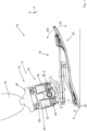
- Figure 1 shows a foot prosthesis 10 according to the invention, which has a lower leg connection part 12, a release device 16 and a foot part 18.
- the connecting element 14 acts as a joint, so that the foot part 18 can be pivoted relative to the lower leg connecting part 12 in a dorsiflexion direction DE, which is indicated by the arrow DE.
- the foot part 18 can also be pivoted in a plantar flexion direction PF that is opposite to the dorsiflexion direction DE.
- the lower leg connecting part 12 is attached to an artificial lower leg (19).
- the foot part 18 has a heel section 20 and a ball section 22.
- the release device 16 serves to inhibit or slightly enable the movement of the foot part 18 relative to the lower leg connecting part 12, depending on the angular position.
- the release device 16 has a first hydraulic cylinder 24, which is connected on the one hand to the foot part 18 via a coupling element 26 and on the other hand to the lower leg connecting part 12.
- the release device 16 has a hydraulic locking device 28, which is in Figure 1 can only be seen in rough outline and in Figure 2a is explained in more detail.
- the release device 16 also has a second hydraulic cylinder 30, which is connected to the first hydraulic cylinder 24 in such a way that a hydraulic fluid 32, in the present case a hydraulic fluid, for example in the form of oil, which is displaced from one of the hydraulic cylinders 24, 30, into the each other hydraulic cylinder 30, 24 flows.
- a hydraulic fluid 32 in the present case a hydraulic fluid, for example in the form of oil, which is displaced from one of the hydraulic cylinders 24, 30, into the each other hydraulic cylinder 30, 24 flows.
- Figure 2a shows a circuit diagram of the release device 16 with the first hydraulic cylinder 24, the second hydraulic cylinder 30 and the inhibiting device 28, which is formed here by an arrangement of hydraulic components.
- the inhibiting device 28 has a first fluid line 34 and a second fluid line 36, both of which connect the hydraulic cylinders 24, 30 to one another.
- the release device 16 has a bridging line 38, which is connected to a cylinder interior 42 of the second hydraulic cylinder 30 in a tap opening 40.
- the tapping point along a longitudinal axis L 32 along the second hydraulic cylinder 30 is adjustable, as explained below.
- a first piston 44 of the first hydraulic cylinder 24 moves in such a way that a cylinder interior 46 enlarges.
- a second piston 48 of the second hydraulic cylinder 30 moves into the cylinder interior 42.
- the piston 48 is at the level of the tap opening 40.
- This situation is in Figure 2a shown.
- a further dorsiflexion movement causes the hydraulic fluid 32 to flow through the first fluid line 34 into the first hydraulic cylinder 24.
- the hydraulic fluid only passes through the first fluid line 34.
- This includes a check valve 50, which in the present case has a sequence valve 52 and a check valve 54.
- the first fluid line 34 contains a throttle 56. It is possible, but not necessary, for the throttle 56 to be designed as an independent component. It is also possible for parts of the first fluid line 34 to have such a small cross section that a throttling effect is achieved.
- the throttle 56 is designed to be adjustable, so that a flow resistance that the first fluid line opposes to the hydraulic fluid can be adjusted.
- the hydraulic fluid flows through the bridging line 38. It is possible for the bridging line 38, as shown, to flow in front of the throttle 56 in the direction of flow first fluid line 34 opens.
- the bridging line 38 can open behind the throttle 56 in the direction of flow, which is shown in dashed lines as the bridging line 38 '.
- the bridging line can also open into the second fluid line 36, which is marked as 38".
- Another throttle which is not shown, is arranged in front of the corresponding confluence point.
- the bridging line 38′′′ opens directly into the first hydraulic cylinder 24. In this case, it is advantageous if the bridging line 38 has its own non-return valve and, if necessary, its own throttle.
- the second fluid line 36 has a second throttle 58 and a second Non-return valve 60. It is possible for the bridging line 38 to open into the second fluid line 36, as shown in dash-dotted lines.
- the first check valve 50 has an opening pressure p opening and only opens when a pressure p 42 in the cylinder interior 42 of the second hydraulic cylinder 30 is exceeded.
- the opening pressure p opening is reached exactly when the projection of the ankle torque M on an axis of rotation D, about which the foot part 18 pivots relative to the lower leg connecting part 12, exceeds a release threshold. If a force acts in the ball section 22 that pushes the foot part 18 in the dorsiflexion direction DE, this torque is viewed as positive. If, on the other hand, the foot part 18 exerts a force that leads to a plantar flexion movement of the foot part, this ankle torque is considered negative.
- FIG. 2b shows schematically that the second hydraulic cylinder 30 has a base body 62 in which a sleeve 64 is rotatably mounted.
- the sleeve 64 has a coupling structure 66 which can be engaged with a suitable tool.
- the inner wall of the sleeve 64 forms the inner cylinder wall of the second hydraulic cylinder 30.
- Several grooves 68.1, 68.2, ... are made in the sleeve 64.
- the sleeve 64 has several bores 70.1, 70.2, ....
- the bores 70.i are arranged angularly offset about the longitudinal axis L 30 .
- hole 70.7 lies in the cutting plane of the drawing. It can be seen that the bore 70.7 is connected to a return channel 72. Hydraulic fluid can therefore reach the outside of the cylinder interior 42 through the bore 70.7 and only through this.
- the sleeve 64 is sealed relative to the base body 62 and the return channel 72 is arranged around an outer contour of the sleeve 64 so that only one bore, here 70.7, is connected to the return channel 72.
- the width of the return channel 72 in the circumferential direction of the sleeve 64 is smaller than the arc length of the angular distance by which the bores 70 are offset from one another.
- the return channel 72 is part of the bridging line 38.
- the groove furthest away from the piston 48 in the present case the groove 70.8, has several bores 74.1, 74.2, ... through which hydraulic fluid can pass into an annular channel 76 in any rotational position of the sleeve 64.
- the annular channel is part of a connecting line 78, which is both part of the first fluid line 34 (cf. Figure 2a ) as well as the second fluid line 36.
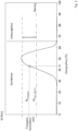
- Figure 3 shows schematically the course of the ankle torque M as a scalar quantity of the gait cycle.
- the release device 16 releases the dorsiflexion movement of the foot part 18. After the swing phase ends and the gait cycle begins again, the ankle torque M temporarily becomes negative. This is the case when the heel section 20 touches the ground. In this case, the release device 16 allows a plantar flexion movement of the foot part 18 (cf. Figure 1 ).
- FIG 4 shows the foot prosthesis 10, in which the foot part 18 is in its zero position relative to the lower leg connecting part 12, which could also be referred to as the neutral position.
- the patient stands in this position.
- the heel section 20 is spaced from the ground U by a heel height A.
- the shoe that has the same heel height A is not shown.
- the pistons 44, 48 of the two hydraulic cylinders 24, 30 are arranged at approximately the same height, which represents a preferred embodiment, but is not necessary.
- Figure 5 shows the foot prosthesis 10 in the zero position when using a shoe with a larger heel height A.
- the tap opening 40 is relocated to another tap point, as described above Figures 2a and 2 B is described. Since at the in Figure 5 shown increased heel height the maximum ankle torque M is smaller than for the in Figure 4 In the case shown, it is advantageous if the opening pressure p opening of the check valve 50 is adjustable.
- Figure 6 shows the foot prosthesis 10 when using a shoe with a lower heel height than in Figure 4 .
- the comparison to the representation in Figure 4 The resulting angular offset is compensated for by adjusting the tapping location of the tapping opening 40.
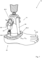
- FIG 7 shows a second embodiment of a foot prosthesis 10 according to the invention.
- the foot part 18 comprises foot cosmetics 80, which gives the prosthesis 10 a natural appearance.
- the foot cosmetics 80 is attached to a base plate 82, which is also part of the foot part 18.
- the connecting element 14 comprises a rigid arm 84 which is articulated on the foot part 18.
- the release device 16 forms a second, variable-length arm 86, which is connected to the foot part 18 at the heel section 20.
- the connecting element 14 has three partial swivel joints, 88.1, 88.2, 88.3, which are all three swivel joints and have respective axes of rotation D 88.1 , D 88.2 and D 88.3 .
- the hydraulic cylinder 24 is articulated with its piston rod on the partial joint 88.2 and with its cylinder housing on the lower leg connecting part 12.
- Figure 8 shows the hydraulic equivalent circuit diagram for the embodiment according to Figure 7 .
- the hydraulic cylinder 24 is designed to be double-acting. A dorsiflexion movement beyond the zero position, which is indicated by the piston 48 in a solid line, results in the hydraulic fluid flowing out of an outlet opening 90, through the first fluid line 34 and through an inlet opening 92 back into the hydraulic cylinder 24.
- a dorsiflexion movement between the maximum plantar flexion position in which the foot part 18 (cf. Figure 7 ) is arranged with maximum plantar reflection relative to the lower leg connecting part 12, and the zero position results in the hydraulic fluid flowing back into the hydraulic cylinder 24 through the tap opening (40) and the bridging line 38 as well as through the throttle 56 and the inlet opening 72.
- a plantar flexion movement causes the hydraulic fluid to flow through the second fluid line 36 and the outlet opening 90 and/or through the bypass line 38.
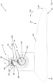
- FIG. 9 shows an embodiment no longer covered by the invention.
- the Hemming device 28 comprises a sliding element 94, which is tensioned onto a hemming structure 98 by a biasing element 96.
- the inhibiting structure 98 is formed on the foot part 18. If the sliding element 94, as indicated by dashed lines and provided with the reference number 94 ', is located in a first section of the inhibiting structure 98, it only offers a small resistance to a dorsiflexion movement. This low resistance is present when the foot part 18 is located between a maximum plantar flexion position and the zero position relative to the lower leg connecting part 12.
- the sliding element 94 also functions as a friction element, so that a frictional force must be overcome in order to rub the sliding element 94 on the inhibiting structure 98.
- FIG. 9 shows the foot prosthesis 10 in its maximum dorsiflexion position.
- the inhibiting device 28 comprises a friction brake 100, by means of which a rotational movement between the foot part 18 and the lower leg connecting part 12 can be braked.
- the friction brake 100 is designed to brake a movement of a pin 102, which is rigidly connected to the foot part 18, and an intermediate ring 104, which could also be referred to as a coupling ring.
- the intermediate ring 104 is designed to be rotatable relative to both the foot part 18 and the lower leg connecting part 12.
- the release device 16 comprises a mechanical non-return element 106, which is connected to the foot part 18 in such a way that a dorsal extension movement of the foot part 18 does not lead to any relative movement between the foot part 18 and the intermediate ring 104.
- the check element 106 allows movement between the intermediate ring 104 and the foot part 18 when the foot part 18 carries out a plantar flexion movement. In this way it is achieved that the friction brake 100 only brakes a dorsiflexion movement of the foot part, but not a plantar flexion movement.
- the release threshold M release can be set.
- the inhibiting structure 98 can be releasably attached relative to the foot part 18 in a direction radial with respect to the axis of rotation D.
- the inhibiting structure 98 is formed on an adjustment part that can be moved in a fixed manner relative to the foot part 18. In this case, this adjustment part can first be detached from the foot part 18, then pivoted relative to the foot part 18 about the axis of rotation D and then attached to the foot part 18 again. In this way, the angular position in which the foot part 18 is in the zero position changes. In this way, the zero position can be set, from which the dorsiflexion movement is more strongly inhibited.
Landscapes
- Health & Medical Sciences (AREA)
- Life Sciences & Earth Sciences (AREA)
- Transplantation (AREA)
- Animal Behavior & Ethology (AREA)
- General Health & Medical Sciences (AREA)
- Engineering & Computer Science (AREA)
- Biomedical Technology (AREA)
- Heart & Thoracic Surgery (AREA)
- Oral & Maxillofacial Surgery (AREA)
- Veterinary Medicine (AREA)
- Public Health (AREA)
- Vascular Medicine (AREA)
- Cardiology (AREA)
- Orthopedic Medicine & Surgery (AREA)
- Dentistry (AREA)
- Physics & Mathematics (AREA)
- Biophysics (AREA)
- Pathology (AREA)
- Medical Informatics (AREA)
- Molecular Biology (AREA)
- Surgery (AREA)
- Physiology (AREA)
- Prostheses (AREA)
Description
- Die Erfindung betrifft eine Fußprothese mit einem Unterschenkel-Anschlussteil, einem Fußteil, einem Verbindungsteil mit Gelenkfunktion, das das Unterschenkel-Anschlussteil mit dem Fußteil verbindet, und einer Freigabevorrichtung, mittels der eine Bewegung des Fußteils relativ zu dem Unterschenkel-Anschlussteil hemmbar und enthemmbar ist, die eine passive Hemmvorrichtung (28) besitzt, und die einen Hydraulikzylinder, der mit dem Fußteil und dem Unterschenkel-Anschlussteil verbunden ist, aufweist.
- Eine derartige Prothese ist aus der
WO2014/057086 A1 bekannt, bei der eine Dämpfung eines um ein Knöchelgelenk verschwenkbaren Fußteils über einen ersten Hydraulikzylinder einstellbar ist, wobei dieser wiederum von einem zweiten Hydraulikzylinder beaufschlagbar ist. Nachteilig an dieser Prothese ist, dass zum Vermeiden eines Stolperns ein Vorderfußteil vorgesehen und angehoben werden muss, was aufwendig ist. - Aus der
EP 1 974 699 A1 ist ein Prothesen- oder Orthesengelenk bekannt, bei dem eine schwenkwinkelabhängige Dämpfung über an einen Drehkolben eingearbeitete Überströmkonturen erreicht wird. Nachteilig an einem derartigen Gelenk ist der komplexe Aufbau und der hohe Fertigungsaufwand,
Aus derUS 8,709,091 B2 ist eine Prothese bekannt, bei der ein Mikroprozessor anhand von Sensordaten erfasst, wann der Gangablauf so weit fortgeschritten ist, dass das Gelenk freigeschaltet werden muss. Nachteilig an einer derartigen Prothese ist der hohe Aufwand bei der Fertigung und der Wartung. - Aus der
WO 2014/039885 A1 ist eine Prothese bekannt, bei der ebenfalls mittels eines Mikroprozessors und einer Vielzahl von Sensoren der Gangablauf erfasst wird. In einer Steuerung der Prothese können Schwellenwerte hinterlegt werden, anhand derer die Aktoren der Prothese angesteuert werden. Auch ein derartiges System ist aufwendig zu fertigen und zu warten. - Aus der
US 2014/0074255 A1 ist ein künstlicher Fuß bekannt, bei dem ein rollfähiges Element verwendet wird, um einen Flüssigkeitskanal genau dann zu verschließen, wenn der Patient steht. Auf diese Weise wird eine Dorsalextensionsbewegung des Fußes dann gestoppt, wenn sich der Schwerpunkt oberhalb des Fußes befindet. Nachteilig an einem derartigen Fuß ist die erhöhte Stolpergefahr. - Aus der
US 2014/0330393 A1 ist ein Fuß bekannt, bei dem zwei Federn dazu verwendet werden, um eine Dorsalextensionsbewegung bis zu einer Nullstellung mit einem ersten Drehmoment zu beaufschlagen und danach mit einem zweiten Drehmoment zu beaufschlagen. Nachteilig an einem derartigen System ist die Geräuschentwicklung. - Nachteilig an bekannten Prothesen ist zudem, dass es vergleichsweise aufwendig ist, die Prothese anzupassen, wenn Schuhe mit unterschiedlichen Absatzhöhen getragen werden.
- Der Erfindung liegt die Aufgabe zugrunde, Nachteile im Stand der Technik zu vermindern.
- Die Erfindung löst das Problem durch eine Fußprothese, deren Hemmvorrichtung so mit dem Hydraulikzylinder verbunden ist, , dass eine Dorsalextensionsbewegung des Fußteils relativ zum Unterschenkel-Anschlussteil in einem Winkelbereich von einer Maximal-Plantarflexionsstellung bis zu einer Nullstellung wenig stark gehemmt wird als eine Dorsal-Extensionsbewegung des Fußteils aus der Nullstellung, und eine Dorsalextensionsbewegung über die Nullstellung hinaus möglich ist. Vorzugsweise ist die Hemmvorrichtung so ausgebildet, dass die Nullstellung einstellbar ist. Die Maximal-Plantarflexionsstellung ist diejenige Stellung, in der das Fußteil maximal plantarflektiert ist.
- Vorteilhaft an einer derartigen Fußprothese ist, dass sie besonders einfach aufgebaut ist. So sind eine Steuerung und Sensoren sowie Aktoren entbehrlich.
- Gegenüber beispielsweise mechanischen Hemmvorrichtungen hat eine hydraulische Hemmvorrichtung den Vorteil, dass sie besonders leise arbeitet.
- Dadurch, dass die Dorsal-Extensionsbewegung zwischen der Maximal-Plantarflexionsstellung und der Nullstellung weniger stark gehemmt wird als über die Nullstellung hinaus, führt dass das Fußteil nach dem Aufsetzen der Ferse zunächst ohne einen großen Widerstand zu leisten relativ zum Unterschenkel-Anschlussteil schwenken kann. Sobald sich der Schwerpunkt des Patienten, der die Fußprothese trägt, über der Fußprothese befindet, wird eine weitere dorsale Extensionsbewegung hingegen stärker gehemmt oder sogar vollständig unterbunden. Das führt dazu, dass der Körper des Patienten nicht an Höhe verliert.
- Hat sich der Schwerpunkt des Körpers des Patienten über den Ballenbereich der Fußprothese bewegt, so überschreitet das Knöchel-Drehmoment einen Freigabe-Schwellenwert und die Hemmvorrichtung gibt gemäß einer bevorzugten Ausführungsform der Prothese die Dorsal-Extensionsbewegung des Fußteils frei. Beim nachfolgenden Abheben der Fußprothese ergibt sich dadurch ein größerer Abstand zwischen dem Boden und der Spitze der Fußprothese, sodass die Gefahr des Stolperns verringert wird. Setzt die Fußprothese zu Beginn des nachfolgenden Gangzyklus auf den Boden auf, so führt das Fußteil eine Plan tarflexionsbewegung aus und der oben beschriebene Ablauf wird erneut durchlaufen.
- Im Rahmen der vorliegenden Beschreibung wird unter dem Unterschenkel-Anschlussteil insbesondere eine Vorrichtung verstanden, die ausgebildet ist zum direkten oder indirekten mechanischen Verbinden mit einem künstlichen oder natürlichen Unterschenkel. Es ist also möglich, nicht aber notwendig, dass ein künstlicher Unterschenkel und/oder ein künstliches Knöchelgelenk vorhanden ist, der unlösbar oder lösbar mit dem Unterschenkel-Anschlussteil verbunden ist.
- Unter dem Fußteil wird insbesondere derjenige Teil der Prothese verstanden, der die Funktion des menschlichen Fußes übernimmt. Insbesondere kann der Fußteil eine Fußkosmetik umfassen, die der Prothese eine Anmutung eines natürlichen Fußes gibt. Eine derartige Fußkosmetik ist jedoch entbehrlich.
- Unter dem Verbindungselement wird insbesondere eine Verbindung zwischen dem Unterschenkel-Anschlussteil und dem Fußteil verstanden, die eine Relativbewegung der beiden Komponenten erlaubt, die der Bewegung eines natürlichen Fußes entspricht. Das Verbindungselement kann ein Drehgelenk aufweisen oder durch ein Drehgelenk gebildet sein, das eine feste Drehachse aufweist. Diese Lage der Drehachse kann vom Drehwinkel des Drehgelenks unabhängig sein.
- Es ist aber auch möglich, dass das Verbindungselement mehrere Teil-Gelenke aufweist und eine momentane Drehachse hat, das heißt, dass sich die Drehachse, mittels der die momentane Drehung des Fußteils relativ zum Unterschenkel-Anschlussteil beschreibbar ist, sich mit der Zeit und/oder dem Fortschritt der Bewegung im Gangzyklus ändert. Es ist auch möglich, dass das Verbindungselement zumindest teilweise als Festkörpergelenk aufgebaut ist. Die meisten Prothesen zielen darauf ab, den natürlichen Bewegungsablauf möglichst gut zu imitieren. Da der menschliche Fuß mehrere Teil-Gelenke hat, besitzen viele Prothesen ein Verbindungselement, das eine mit der Zeit in seiner Lage verändernde Drehachse besitzt. Die Erfindung bezieht sich auch auf Prothesen mit solchen Verbindungselementen.
- Unter einer Dorsal-Extensionsbewegung des Fußteils aus der Nullstellung wird eine Schwenkbewegung des Fußteils verstanden, die in Dorsal-Extensionsrichtung über die Nullstellung hinaus erfolgt.
- Vorzugsweise verbindet das Verbindungselement das Unterschenkel-Anschlussteil wie ein Knöchelgelenk mit dem Fußteil. Hierunter ist insbesondere zu verstehen, dass das Verbindungselement die Bewegung des menschlichen Knöchelgelenks nachbildet. Es kann sich daher bei dem Verbindungselement um ein Drehgelenk handeln, das ist aber nicht notwendig.
- Vorzugsweise ist das Verbindungselement so ausgebildet, dass es einer Dorsal- und/oder Plantar-Bewegung einen, beispielsweise um zumindest den Faktor fünf, geringeren Widerstand entgegensetzt als einer Medial- oder Lateralbewegung.
- Vorzugsweise ist das Fußteil relativ zum Unterschenkel-Anschlussteil schwenkbar. Darunter wird insbesondere verstanden, dass die Freigabevorrichtung eine Bewegung zwischen Fußteil und Unterschenkel-Anschlussteil so wenig behindert, dass das Fußteil im normalen Gangzyklus eine Dorsalextensionsbewegung ausführt oder ausführen kann. Vorzugsweise ist die Freigabevorrichtung so ausgebildet, dass sie einer Dorsalextensionsbewegung des Fußteils relativ zum Unterschenkel-Anschlussteil über die Nutstellung hinaus einen zumindest dreifach so hohen Widerstand entgegensetzt wie zwischen der Maximal-Plantarflexionsstellung.
- Unter dem Merkmal, dass die Hemmvorrichtung eine passive Hemmvorrichtung ist, wird insbesondere verstanden, dass das Umschalten ohne einen Aktor erfolgt. Ein Aktor ist ein Bauteil, das von außen steuerbar durch Energieeinsatz ein anderes Bauteil bewegt. Insbesondere ist die Hemmvorrichtung aktorfrei und/oder energiespeicherlos. Vorzugsweise ist die Hemmvorrichtung so aufgebaut, dass die Energie, die zum Übergang von einer Freigabestellung, in der die Dorsalextensionsbewegung weniger stark gehemmt ist, in eine Freigabestellung, in der die Dorsalextensionsbewegung stärker gehemmt ist, notwendig ist, mechanische, insbesondere hydraulische Energie ist. Insbesondere ist die Freigabevorrichtung eine passive hydraulische Freigabevorrichtung.
- Unter der Nullstellung wird insbesondere diejenige Stellung des Fußteils relativ zum Unterschenkel-Anschlussteil verstanden, bei der der Übergang stattfindet von einer weniger stark gehemmten Schwenkbarkeit in Dorsalextensionsrichtung zu einer stärker gehemmten, insbesondere unterdrückten, Schwenkbarkeit in Dorsalextensionsrichtung. Es sei darauf hingewiesen, dass es möglich, nicht aber notwendig ist, dass die Maximal-Plantarflexionsstellung im Gangablauf erreicht wird. Vorzugsweise ist die Nullstellung aber so gewählt, dass im Gangablauf eine Stellung des Fußteils zwischen der Nullstellung und der Maximal-Plantarflexionsstellung erreicht wird und/oder dass das Fußteil in der Nullstellung ist, wenn der Patient steht.
- In anderen Worten lassen sich zwei Winkelbereiche unterscheiden: die Winkel zwischen der Maximal-Plantarflexionsstellung und der Nullstellung und die Winkel von der Nullstellung bis zu einer Maximal-Dorsalextensionsstellung. Im erstgenannten Winkelbereich ist eine Dorsalextensionsbewegung leicht möglich, im zweitgenannten Winkelbereich deutlich schwerer oder nicht.
- Unter dem Merkmal, dass der Hydraulikzylinder mit dem Fußteil und dem Unterschenkel-Anschlussteil verbunden ist, wird insbesondere verstanden, dass ein bewegliches Teil des Hydraulikzylinders, also das Gehäuse oder die Kolbenstange, mit dem Fußteil und das jeweils andere bewegliche Teil mit dem Unterschenkel-Anschlussteil verbunden ist.
- Gemäß einer bevorzugten Ausführungsform ist die Freigabevorrichtung so ausgebildet, dass sie die Dorsalextensionsbewegung des Fußteils über die Nullstellung und nur dann freigibt, wenn ein Knöchel-Drehmoment, das am Fußteil anliegt, oberhalb eines vorgegebenen Freigabe-Schwellenwerts liegt. Das hat den Vorteil, dass es, wie oben beschrieben, am Ende der Standphase im Gangzyklus zu einer Dorsalextensionsbewegung des Fußteils relativ zum Unterschenkel-Anschlussteil über die Nullstellung hinaus kommt, was in der nachfolgenden Schwungphase einen Abstand zwischen der Spitze des Fußes und dem Boden verringert und so die Stolpergefahr minimiert.
- Es ist möglich, aber entbehrlich, dass der Drehmoment-Schwellenwert als Drehmoment bekannt ist. Insbesondere ist es möglich, dass der Drehmoment-Schwellenwert hin zu größeren und/oder kleineren Drehmoment-Schwellenwerten veränderbar ist, ohne dass der absolute Wert des Drehmoments bekannt ist. Wie groß der jeweilige Drehmoment-Schwellenwert in Newtonmeter ist, kann also bekannt sein, das ist aber nicht notwendig.
- Der Drehmoment-Schwellenwert kann insbesondere ermittelt werden, indem eine lotrecht wirkende Kraft auf das Unterschenkel-Anschlussteil ausgeübt, danach das Unterschenkel-Anschlussteil gemäß dem Neigungsverlauf im Gangzyklus geneigt und der Punkt erfasst wird, in dem die Prothese die Kraft in den Boden einleitet. Die Projektion des (äußeren) Vektorprodukts aus der Kraft und dem Hebelarm zu dem Zeitpunkt, in dem die Freigabevorrichtung aus der Arretierstellung in die Freigabestellung auf die Drehachse schaltet, entspricht dem Drehmoment-Schwellenwert, der positiv ist.
- Die Freigabevorrichtung kann parallel oder seriell zu einem weiteren federnden Element der Prothese angeordnet sein. Beispielsweise ist das federnde Element Teil des Fußteils. Das federnde Element umfasst vorzugsweise eine Karbonfeder. Unter einer parallelen Anordnung wird verstanden, dass sich die mechanischen Widerstände der Freigabevorrichtung und des federnden Elements addieren. Unter einer seriellen Anordnung wird verstanden, dass sich die Federwege der Freigabevorrichtung und des federnden Elements addieren.
- Die Freigabevorrichtung kann druckbelastet oder zugbelastet angeordnet sein. Ist die Freigabevorrichtung druckbelastet, so wird sie am Ende der Standphase zusammengedrückt. Ist die Freigabevorrichtung zugbelastet, so wird sie am Ende der Standphase auseinandergezogen.
- Gemäß einer bevorzugten Ausführungsform umfasst die Prothese eine Vorspannfeder, die so angeordnet ist, dass sie beim Fersenauftritt im Anschlag ist.
- Gemäß einer bevorzugten Ausführungsform ist die Hemmvorrichtung eine hydraulische Hemmvorrichtung. Das heißt insbesondere, dass die hemmende Wirkung der Hemmvorrichtung zumindest auch, insbesondere ausschließlich, durch hydraulische Komponenten bewirkt wird.
- Erfindungsgemäß weist die Freigabevorrichtung einen Hydraulikzylinder, der mit dem Fußteil und dem Unterschenkel-Anschlussteil verbunden ist, auf und die Hemmvorrichtung ist so mit dem Hydraulikzylinder verbunden, dass eine Dorsalextensionsbewegung des Fußteils relativ zum Unterschenkel-Anschlussteil in einem Winkelbereich von einer Maximal-Plantarflexionsstellung, in der das Fußteil in der maximal plantarflektierten Stellung ist, bis zu einer Nullstellung weniger stark gehemmt wird als eine Dorsalextensionsbewegung des Fußteils aus der Nullstellung. Eine derartige Fußprothese ist leise und wartungsarm.
- Erfindungsgemäß ist insbesondere eine Fußprothese mit (a) einem Unterschenkel-Anschlussteil,(b) einem Fußteil, (c) einem Verbindungselement mit Gelenkfunktion, das das Unterschenkel-Anschlussteil mit dem Fußteil verbindet, und (d) einer Freigabevorrichtung, mittels der eine Bewegung des Fußteils relativ zum Unterschenkel-Anschlussteil hemmbar und enthemmbar ist, wobei (e) die Freigabevorrichtung eine passive hydraulische Hemmvorrichtung besitzt, die so ausgebildet ist, dass eine Dorsalextensionsbewegung des Fußteils relativ zum Unterschenkel-Anschlussteil in einem Winkelbereich von einer Maximal-Plantarflexionsstellung, in der das Fußteil in der maximal plantarflektierten Stellung ist, bis zu einer Nullstellung weniger stark gehemmt wird als eine Dorsalextensionsbewegung des Fußteils aus der Nullstellung, wobei diese Fußprothese vorzugsweise die im vorigen Absatz beschriebene Freigabevorrichtung aufweist. Die in der vorliegenden Beschreibung dargelegten bevorzugten Ausführungsformen beziehen sich auch auf diese Erfindung.
- Vorzugsweise besitzt die Hemmvorrichtung eine erste Fluidleitung, durch die Hydraulikfluid fließt, wenn das Fußteil eine Dorsalextionsbewegung über die Nullstellung hinaus ausführt, wobei die erste Fluidleitung einen ersten Strömungswiderstand hat, wobei die Hemmvorrichtung zudem eine Überbrückungsleitung besitzt, über die das Hydraulikfluid fließt, wenn das Fußteil eine Dorsalextionsbewegung zwischen der Maximal-Plantarflexionsstellung und der Nullstellung ausführt, wobei die Überbrückungsleitung einen Überbrückungs-Strömungswiderstand hat, der kleiner ist als der ersten Strömungswiderstand. Hierunter wird insbesondere bestanden, dass der Überbrückungs-Strömungswiderstand höchstens ein Drittel, insbesondere höchstens ein Fünftel, des ersten Strömungswiderstands beträgt. Auf diese Weise ist eine Plantarflexionsbewegung zwischen der Maximal-Plantarflexionsstellung und der Nullstellung deutlich einfacher möglich als eine Dorsalextionsbewegung über die Nullstellung hinaus.
- Das führt, wie oben bereits beschrieben, dazu, dass nach dem Aufsetzen des Prothesenfußes das Gewicht einfach auf den Prothesenfuß übertragen werden kann. Sobald das Gewicht vollständig auf den Prothesenfuß übertragen ist, muss gemäß einer bevorzugten Ausführungsform das Knöchel-Drehmoment den Freigabe-Schwellenwert überschreiten, damit es zu einer weiteren Dorsalextensionsbewegung kommt. Es ergibt sich so ein natürlicher Bewegungsablauf bei geringer Stolpergefahr.
- Im Rahmen der vorliegenden Beschreibung wird unter dem Strömungswiderstand der Quotient aus Druck und Durchfluss verstanden, beispielsweise bei einem Durchfluss von 1 Milliliter pro Sekunde.
- Vorzugsweise ist die Überbrückungsleitung so mit dem Hydraulikzylinder verbunden, dass eine Abzapfstelle einer Abzapföffnung entlang einer Längsachse des Hydraulikzylinders zur Einstellung der Nullstellung veränderbar ist. Die Abzapföffnung ist diejenige Öffnung, aus der das Hydraulikfluid aus dem Hydraulikzylinder in die Überbrückungsleitung gelangen kann. Sobald der Kolben des Hydraulikzylinders die Abzapfstelle passiert hat, hemmt die Hemmvorrichtung eine weitere Bewegung des Kolbens oder unterbindet sie, insbesondere bis das Knöchel-Drehmoment den Freigabe-Schwellenwert überschritten hat.
- Gemäß einer bevorzugten Ausführungsform weist die erste Fluidleitung eine Rückschlagarmatur auf, die ausgebildet ist zum Unterbinden einer Dorsalextensionsbewegung des Fußteils über die Nullstellung hinaus, solange das Knöchel-Drehmoment höchstens nicht oberhalb des Freigabe-Schwellenwerts liegt, und zum Freigeben der Dorsalextensionsbewegung über die Nullstellung hinaus, wenn das Knöchel-Drehmoment oberhalb des Freigabe-Schwellenwerts liegt.
- Eine derartige Rückschlagarmatur ist robust, langlebig und leise und zudem einfach herzustellen. Unter einer Rückschlagarmatur wird eine Komponente verstanden, die einen Fluss des Hydraulikfluids lediglich in eine Durchflussrichtung erlaubt. Beispielsweise handelt es sich bei der Rückschlagarmatur um ein Rückschlagventil oder ein Folgeventil.
- Günstig ist es, wenn die Hemmvorrichtung eine zweite Fluidleitung aufweist, durch die Hydraulikfluid fließt, wenn das Fußteil eine Plantarflexionsbewegung ausführt, wobei die zweite Fluidleitung einen zweiten Strömungswiderstand hat, der kleiner ist als der erste Strömungswiderstand. Hierunter wird insbesondere verstanden, dass der zweite Strömungswiderstand höchstens ein Drittel, insbesondere höchstens ein Fünftel, des ersten Strömungswiderstands der ersten Fluidleitung beträgt. Das führt dazu, dass eine Plantarflexionsbewegung, wie sie vom Fußteil zu Beginn des Gangzyklus beim Aufsetzen mit der Ferse ausgeführt wird, vergleichsweise einfach möglich ist. Es ergibt sich dadurch ein mit dem natürlichen Gangbild.
- Gemäß einer bevorzugten Ausführungsform besitzt die Freigabevorrichtung einen zweiten Hydraulikzylinder, der so mit der Hemmvorrichtung verbunden ist, dass eine Dorsalextensionsbewegung des Fußteils über die Nullstellung hinaus dazu führt, dass Hydraulikfluid aus dem zweiten Hydraulikzylinder durch die erste Fluidleitung in den ersten Hydraulikzylinder fließt, eine Dorsalextensionsbewegung zwischen der Maximal-Plantarflexionsstellung und der Nullstellung dazu führt, dass das Hydraulikfluid durch die Überbrückungsleitung fließt und dass eine Plantarflexionsbewegung dazu führt, dass das Hydraulikfluid aus dem ersten Hydraulikzylinder durch die zweite Fluidleitung in den zweiten Hydraulikzylinder fließt.
- Es sei darauf hingewiesen, dass die erste Fluidleitung, die zweite Fluidleitung und/oder die Überbrückungsleitung gemeinsame Leitungsabschnitte aufweisen können.
- Alternativ ist der Hydraulikzylinder doppeltwirkend ausgebildet und so mit der Hemmvorrichtung verbunden, dass eine Dorsalextensionsbewegung des Fußteils über die Nullstellung hinaus dazu führt, dass das Hydraulikfluid aus einer Auslassöffnung, die an einem Auslassende des Hydraulikzylinders angeordnet ist, durch eine erste Fluidleitung und gegebenenfalls durch eine Einlassöffnung, die an einem dem Auslassende gegenüberliegenden Einlassende angeordnet ist, zurück in den Hydraulikzylinder fließt, dass eine Dorsalextensionsbewegung zwischen der Maximal-Plantarflexionsbewegung und der Nullstellung dazu führt, dass das Hydraulikfluid durch die Abzapföffnung und die Überbrückungsleitung fließt und dass eine Plantarflexionsbewegung dazu führt, dass das Hydraulikfluid durch die zweite Fluidleitung fließt. Es ist zwar denkbar und erfindungsgemäß, dass neben einem doppeltwirkenden Hydraulikzylinder ein zweiter Hydraulikzylinder vorhanden ist, das führt aber zu einem erhöhten Fertigungsaufwand, der in den meisten Fällen unerwünscht ist.
- Gemäß einer bevorzugten Ausführungsform umfasst die Freigabevorrichtung eine Reibbremse und ein mechanisches Rückschlagelement, wobei die Reibbremse und das Rückschlagelement so angeordnet sind, dass eine Dorsalextensionsbewegung des Fußteils stärker gebremst wird als eine Plantarflexionsbewegung. Beispielsweise ist die Reibbremse mittels einer Feder auf eine Hemmstruktur vorgespannt.
- Günstig ist es, wenn die Hemmvorrichtung einen Zapfen, der starr mit dem Fußteil verbunden ist, einen Außenkranz, der starr mit dem Unterschenkel-Anschlussteil verbunden ist, und einen Zwischenring, der relativ zum Zapfen und relativ zum Außenkranz drehbar gelagert ist, aufweist, wobei das mechanische Rückschlagelement so angeordnet ist, dass sich der Zwischenring nur bei einer Dorsalextensionsbewegung des Fußteils relativ zum Zapfen oder relativ zum Unterschenkel-Anschlussteil bewegt. Auf diese Weise wird erreicht, dass die Reibbremse, die gemäß einer bevorzugten Ausführungsform eine Reibkraft zwischen dem Zwischenring und entweder dem Unterschenkel-Anschlussteil oder dem Fußteil ausübt, diese Reibkraft nur dann aufbringt, wenn das Fußteil eine Dorsalextensionsbewegung durchführt.
- Im Folgenden wird die Erfindung anhand der beigefügten Zeichnungen näher erläutert. Dabei zeigt
- Figur 1
- eine erfindungsgemäße Fußprothese in dorsalextendierter Stellung am Ende der Schwungphase eines Gangzyklus,
- Figur 2a
- ein Schaltbild der Freigabevorrichtung der Fußprothese gemäß Figur 1,
- Figur 2b
- eine Detailansicht des zweiten Hydraulikzylinders,
- Figur 3
- eine schematische Darstellung des Gangzyklus zur Erläuterung der Wirkungsweise der erfindungsgemäßen Fußprothese,
- Figur 4
- die Fußprothese in ihrer Nullstellung, die auch als Neutralposition bezeichnet werden könnte,
- Figur 5
- die Fußprothese in Nullstellung, wenn sie in einem Schuh mit einer höheren Absatzhöhe verwendet wird,
- Figur 6
- die Fußprothese in ihrer Nullstellung, wenn sie in einem Schuh mit einer niedrigeren Absatzhöhe verwendet wird, und
- Figur 7
- eine perspektivische Ansicht einer Fußprothese gemäß einer zweiten Ausführungsform der Erfindung und
- Figur 8
- ein Schaltbild einer Freigabevorrichtung für eine Fußprothese gemäß einer zweiten Ausführungsform der Erfindung.
- Figur 9
- zeigt eine erfindungsgemäße Fußprothese gemäß einer zweiten Ausführungsform der Erfindung.
-
Figur 1 zeigt eine erfindungsgemäße Fußprothese 10, die ein Unterschenkel-Anschlussteil 12, eine Freigabevorrichtung 16 und ein Fußteil 18 aufweist. Das Verbindungselement 14 wirkt als Gelenk, sodass das Fußteil 18 relativ zum Unterschenkel-Anschlussteil 12 in eine Dorsalextensionsrichtung DE schwenkbar ist, die durch den Pfeil DE angedeutet ist. Das Fußteil 18 kann zudem in eine der Dorsalextensionsrichtung DE entgegengesetzte Plantarflexionsrichtung PF geschwenkt werden. Das Unterschenkel-Anschlussteil 12 ist an einem künstlichen Unterschenkel (19) befestigt. - Das Fußteil 18 besitzt einen Fersenabschnitt 20 und einen Ballenabschnitt 22. Die Freigabevorrichtung 16 dient dazu, die Bewegung des Fußteils 18 relativ zum Unterschenkel-Anschlussteil 12 je nach Winkelstellung zu hemmen oder leicht zu ermöglichen. Dazu besitzt die Freigabevorrichtung 16 einen ersten Hydraulikzylinder 24, der einerseits über ein Koppelelement 26 mit dem Fußteil 18 und andererseits mit dem Unterschenkel-Anschlussteil 12 verbunden ist. Zudem besitzt die Freigabevorrichtung 16 eine hydraulische Hemmvorrichtung 28, die in
Figur 1 nur in groben Zügen zu erkennen ist und inFigur 2a näher erläutert wird. - Die Freigabevorrichtung 16 besitzt zudem einen zweiten Hydraulikzylinder 30, der so mit dem ersten Hydraulikzylinder 24 verbunden ist, dass ein Hydraulikfluid 32, im vorliegenden Fall eine Hydraulikflüssigkeit, beispielsweise in Form von Öl, die aus einem der Hydraulikzylinder 24, 30 verdrängt wird, in den jeweils anderen Hydraulikzylinder 30, 24 fließt.
-
Figur 2a zeigt ein Schaltbild der Freigabevorrichtung 16 mit dem ersten Hydraulikzylinder 24, dem zweiten Hydraulikzylinder 30 und der Hemmvorrichtung 28, die hier durch eine Anordnung hydraulischer Komponenten gebildet ist. Die Hemmvorrichtung 28 besitzt eine erste Fluidleitung 34 und eine zweite Fluidleitung 36, die jeweils beide die Hydraulikzylinder 24, 30 miteinander verbinden. Zudem besitzt die Freigabevorrichtung 16 eine Überbrückungsleitung 38, die in einer Abzapföffnung 40 mit einem Zylinderinnenraum 42 des zweiten Hydraulikzylinders 30 in Verbindung steht. Die Abzapfstelle entlang einer Längsachse L32 entlang des zweiten Hydraulikzylinders 30 ist einstellbar, wie weiter unten erläutert wird. - Führt das Fußteil 18 (vgl.
Figur 1 ) eine Dorsalextensionsbewegung durch, so bewegt sich ein erster Kolben 44 des ersten Hydraulikzylinders 24 so, dass sich ein Zylinderinnenraum 46 vergrößert. Zudem bewegt sich ein zweiter Kolben 48 des zweiten Hydraulikzylinders 30 in den Zylinderinnenraum 42 hinein. - Befindet sich das Fußteil 18 (vgl.
Figur 1 ) relativ zum Unterschenkel-Anschlussteil 12 in seiner Nullstellung, so ist der Kolben 48 auf Höhe der Abzapföffnung 40. Diese Situation ist inFigur 2a gezeigt. Eine weitere Dorsalextensionsbewegung führt dazu, dass das Hydraulikfluid 32 durch die erste Fluidleitung 34 in den ersten Hydraulikzylinder 24 fließt. Dazu passiert das Hydraulikfluid ausschließlich die erste Fluidleitung 34. Diese umfasst eine Rückschlagarmatur 50, die im vorliegenden Fall ein Folgeventil 52 und ein Rückschlagventil 54 aufweist. Zudem enthält die erste Fluidleitung 34 eine Drossel 56. Es ist möglich, nicht aber notwendig, dass die Drossel 56 als eigenständiges Bauteil ausgebildet ist. Es ist auch möglich, dass Teile der ersten Fluidleitung 34 einen so kleinen Querschnitt aufweisen, dass eine Drosselwirkung erzielt wird. Gemäß einer bevorzugten Ausführungsform ist die Drossel 56 verstellbar ausgebildet, sodass ein Strömungswiderstand, den die erste Fluidleitung dem Hydraulikfluid entgegensetzt, einstellbar ist. - Befindet sich der zweite Kolben 48 vor der Abzapföffnung 40, wie es durch den gestrichelten Kolben 48' angedeutet ist, so fließt das Hydraulikfluid durch die Überbrückungsleitung 38. Es ist möglich, dass die Überbrückungsleitung 38 wie eingezeichnet bezüglich einer Strömungsrichtung vor der Drossel 56 in die erste Fluidleitung 34 einmündet.
- Alternativ ist es möglich, dass die Überbrückungsleitung 38 in Strömungsrichtung hinter der Drossel 56 einmündet, was als Überbrückungsleitung 38' gestrichelt eingezeichnet ist. Die Überbrückungsleitung kann zudem in die zweite Fluidleitung 36 münden, was als 38" gekennzeichnet ist. Es ist zudem möglich, dass vor der entsprechenden Einmündungsstelle eine weitere Drossel angeordnet ist, die nicht eingezeichnet ist. Gemäß einer weiteren Ausführungsform mündet die Überbrückungsleitung 38‴ direkt in den ersten Hydraulikzylinder 24. In diesem Fall ist es günstig, wenn die Überbrückungsleitung 38 eine eigene Rückschlagarmatur und gegebenenfalls eine eigene Drossel aufweist.
- Führt das Fußteil 18 eine Plantarflexionsbewegung aus, so bewegt sich der erste Kolben 44 in den Zylinderinnenraum des ersten Hydraulikzylinders 24 und das Hydraulikfluid fließt nur durch die zweite Fluidleitung 36 in den zweiten Hydraulikzylinder 30. Die zweite Fluidleitung 36 besitzt eine zweite Drossel 58 und eine zweite Rückschlagarmatur 60. Es ist möglich, dass die Überbrückungsleitung 38 wie strichpunktiert eingezeichnet ist, in die zweite Fluidleitung 36 mündet.
- Die erste Rückschlagarmatur 50 besitzt einen Öffnungsdruck pöffnung und öffnet erst, wenn ein Druck p42 im Zylinderinnenraum 42 des zweiten Hydraulikzylinders 30 überschritten ist. Der Öffnungsdruck pöffnung wird genau dann erreicht, wenn die Projektion des Knöchel-Drehmoments
M auf eine Drehachse D, um die das Fußteil 18 relativ zum Unterschenkel-Anschlussteil 12 schwenkt, einen Freigabe-Schwellenwert überschreitet. Wirkt im Ballenabschnitt 22 eine Kraft, die das Fußteil 18 in Dorsalextensionsrichtung DE drückt, so wird diese Drehmoment als positiv angesehen. Wirkt das Fußteil 18 hingegen eine Kraft, die zu einer Plantarflexionsbewegung des Fußteils führt, so wird dieses Knöchel-Drehmoment als negativ betrachtet. -
Figur 2b zeigt schematisch, dass der zweite Hydraulikzylinder 30 einen Grundkörper 62 aufweist, in dem eine Hülse 64 drehbar gelagert ist. Die Hülse 64 besitzt eine Koppelstruktur 66, in die mit einem geeigneten Werkzeug eingegriffen werden kann. - Die Innenwandung der Hülse 64 bildet die Zylinderinnenwand des zweiten Hydraulikzylinders 30. In die Hülse 64 sind mehrere Nuten 68.1, 68.2, ... eingebracht. Zudem besitzt die Hülse 64 mehrere Bohrungen 70,1, 70.2, .... Im vorliegenden Fall besitzt, was eine bevorzugten Ausführungsform darstellt, jede Nut 68.i (i=1,2,...) genau eine Bohrung 70.i. Die Bohrungen 70.i sind winkelversetzt um die Längsachse L30 angeordnet. Die Bohrung 70.7 liegt im vorliegenden Fall in der Schnittebene der Zeichnung. Es ist zu erkennen, dass die Bohrung 70.7 mit einem Rückführkanal 72 verbunden ist. Hydraulikfluid kann daher durch die Bohrung 70.7 und nur durch diese aus dem Zylinderinnenraum 42 nach außen gelangen.
- Die Hülse 64 ist gegenüber dem Grundkörper 62 abgedichtet und der Rückführkanal 72 ist so um eine Außenkontur der Hülse 64 herum angeordnet, dass stets nur eine Bohrung, hier 70.7, mit dem Rückführkanal 72 verbunden ist. Insbesondere ist die Breite des Rückführkanals 72 in Umfangsrichtung der Hülse 64 kleiner als die Bogenlänge desjenigen Winkelabstands, um den die Bohrungen 70 gegeneinander versetzt sind. Der Rückführkanal 72 ist Teil der Überbrückungsleitung 38.
- Die dem Kolben 48 am weitesten beabstandete Nut, im vorliegenden Fall die Nut 70.8, besitzt mehrere Bohrungen 74.1, 74.2, ..., durch die Hydraulikfluid bei jeder Drehstellung der Hülse 64 in einen Ringkanal 76 gelangen kann. Der Ringkanal ist Teil einer Anschlussleitung 78, die sowohl Teil der ersten Fluidleitung 34 (vgl.
Figur 2a ) als auch der zweiten Fluidleitung 36 ist. -
Figur 3 zeigt schematisch den Verlauf des Knöchel-Drehmoments M als skalare Größe vom Gangzyklus. - Es ist zu erkennen, dass im Stehen ein Knöchel-Drehmoment M einen Maximalwert Mmax,Stehen nicht überschreitet. Beim Gehen hingegen übersteigt das Knöchel-Drehmoment M den Wert Mmax,Stehen. Solange der Freigabe-Schwellenwert MFreigabe nicht überschritten ist, sperrt die Freigabevorrichtung 16 (vgl.
Figur 1 ) die Bewegung des Fußteils 18. - Ist der Freigabe-Schwellenwert MFreigabe überschritten, gibt die Freigabevorrichtung 16 die Dorsalextensionsbewegung des Fußteils 18 frei. Nach Ende der Schwungphase und erneutem Beginn des Gangzyklus wird das Knöchel-Drehmoment M zeitweise negativ. Das ist dann der Fall, wenn der Fersenabschnitt 20 den Boden berührt. Die Freigabevorrichtung 16 erlaubt in diesem Fall eine Plantarflexionsbewegung des Fußteils 18 (vgl.
Figur 1 ). -
Figur 4 zeigt die Fußprothese 10, bei der das Fußteil 18 relativ zum Unterschenkel-Anschlussteil 12 in seiner Nullstellung ist, die auch als Neutralposition bezeichnet werden könnte. In dieser Position steht der Patient. Der Fersenabschnitt 20 ist um eine Absatzhöhe A vom Untergrund U beabstandet. Der Schuh, der die gleiche Absatzhöhe A hat, ist nicht mit eingezeichnet. In der inFigur 4 gezeigten Position liegen auf dem Fersenabschnitt 20 und dem Ballenabschnitt 22 ungefähr gleich große Kräfte, die über den nicht eingezeichneten Schuh in den Untergrund U eingeleitet werden. Es ist zu erkennen, dass die Kolben 44, 48 der beiden Hydraulikzylinder 24,30 auf ungefähr gleicher Höhe angeordnet sind, was eine bevorzugte Ausführungsform darstellt, nicht aber notwendig ist. -
Figur 5 zeigt die Fußprothese 10 in der Nullstellung bei Verwendung eines Schuhs mit einer größeren Absatzhöhe A. Um den zusätzlichen Winkelversatz des Fußteils 18 im Vergleich zu der Nullstellung bei mittlerer Absatzhöhe, wie sie inFigur 4 gezeigt ist, herzustellen, wird die Abzapföffnung 40 an eine andere Abzapfstelle verlegt, wie dies oben inFiguren 2a und2b beschrieben ist. Da bei der inFigur 5 gezeigten erhöhten Absatzhöhe das maximale Knöchel-Drehmoment M kleiner ist als für den inFigur 4 gezeigten Fall, ist es vorteilhaft, wenn der Öffnungsdruck pöffnung der Rückschlagarmatur 50 einstellbar ist. -
Figur 6 zeigt die Fußprothese 10 bei Verwendung eines Schuhs mit einer geringeren Absatzhöhe als inFigur 4 . Auch in diesem Fall wird der im Vergleich zur Darstellung inFigur 4 eintretende Winkelversatz durch Verstellen des Abzapforts der Abzapföffnung 40 kompensiert. -
Figur 7 zeigt eine zweite Ausführungsform einer erfindungsgemäßen Fußprothese 10. Das Fußteil 18 umfasst eine Fußkosmetik 80, die der Prothese 10 ein natürliches Aussehen verleiht. Die Fußkosmetik 80 ist an einer Standplatte 82 befestigt, die ebenfalls Teil des Fußteils 18 ist. Das Verbindungselement 14 umfasst einen starren Arm 84, der am Fußteil 18 angelenkt ist. Die Freigabevorrichtung 16 bildet einen zweiten, längenveränderlichen Arm 86, der am Fersenabschnitt 20 mit dem Fußteil 18 verbunden ist. - Das Verbindungselement 14 weist drei Teil-Drehgelenke, 88.1, 88.2, 88.3, die alle drei Drehgelenke sind und jeweilige Drehachsen D88.1, D88.2 und D88.3 aufweisen. Bei Bewegung der Prothese 10 dreht sich das Fußteil 18 relativ zum Unterschenkel-Anschlussteil 12 um eine Drehachse Deff=D88.2. Der Hydraulikzylinder 24 ist mit seiner Kolbenstange am Teilgelenk 88.2 und mit seinem Zylindergehäuse am Unterschenkel-Anschlussteil 12 angelenkt.
-
Figur 8 zeigt das hydraulische Ersatzschaltbild für die Ausführungsform gemäßFigur 7 . Der Hydraulikzylinder 24 ist doppeltwirkend ausgebildet. Eine Dorsalextensionsbewegung über die Nullstellung hinaus, die durch den Kolben 48 in durchgezogener Linie angedeutet ist, führt dazu, dass das Hydraulikfluid aus einer Auslassöffnung 90, durch die erste Fluidleitung 34 und durch eine Einlassöffnung 92 zurück in den Hydraulikzylinder 24 fließt. - Eine Dorsalextensionsbewegung zwischen der Maximal-Plantarflexionsstellung, in der das Fußteil 18 (vgl.
Figur 7 ) maximal plantar reflektiert relativ zum Unterschenkel-Anschlussteil 12 angeordnet ist, und der Nullstellung führt dazu, dass das Hydraulikfluid durch die Abzapföffnung (40) und die Überbrückungsleitung 38 sowie durch die Drossel 56 und die Einlassöffnung 72 zurück in den Hydraulikzylinder 24 fließt. Eine Plantarflexionsbewegung führt dazu, dass das Hydraulikfluid durch die zweite Fluidleitung 36 und die Auslassöffnung 90 und /oder durch die Überbrückungsleitung 38 fließt. -
Figur 9 zeigt eine nicht mehr von der Erfindung umfasste Ausführungsform. Die Hemmvorrichtung 28 umfasst ein Gleitelement 94, das durch ein Vorspannelement 96 auf eine Hemmstruktur 98 zu gespannt wird. Die Hemmstruktur 98 ist im vorliegenden Fall am Fußteil 18 ausgebildet. Befindet sich das Gleitelement 94, wie gestrichelt angedeutet und mit der Bezugszahl 94' versehen, in einem ersten Abschnitt der Hemmstruktur 98, so setzt es eine Dorsalextensionsbewegung nur einen geringen Widerstand entgegen. Dieser geringe Widerstand liegt an, wenn das Fußteil 18 relativ zum Unterschenkel-Anschlussteil 12 sich zwischen einer Maximal-Plantarflexionsstellung und der Nullstellung befindet. Das Gleitelement 94 fungiert zudem als Reibelement, sodass zum Reiben des Gleitelements 94 an Hemmstruktur 98 eine Reibkraft überwunden werden muss. - Befindet sich das Fußteil 18 in seiner Nullstellung, so befindet sich das Gleitelement 94 an einer Stelle, an der eine weitere Bewegung nur gegen die Federkraft des Vorspannelements 96 möglich ist. Das ist nur möglich, wenn am Fußteil 18 ein Knöchel-Drehmoment anliegt, das den Freigabe-Schwellenwert überschreitet.
Figur 9 zeigt die Fußprothese 10 in ihrer Maximal-Dorsalextensionsstellung. - Die Hemmvorrichtung 28 umfasst eine Reibbremse 100, mittels der eine Drehbewegung zwischen Fußteil 18 und Unterschenkel-Anschlussteil 12 bremsbar ist. Im vorliegenden Fall ist die Reibbremse 100 zum Bremsen einer Bewegung eines Zapfens 102, der starr mit dem Fußteil 18 verbunden ist, und einem Zwischenring 104, der auch als Kupplungsring bezeichnet werden könnte, ausgebildet. Der Zwischenring 104 ist drehbar sowohl relativ zum Fußteil 18 als auch zum Unterschenkel-Anschlussteil 12 ausgebildet.
- Die Freigabevorrichtung 16 umfasst ein mechanisches Rückschlagelement 106, das so mit dem Fußteil 18 verbunden ist, dass eine Dorsal-Extensionsbewegung des Fußteils 18 zu keiner Relativbewegung zwischen dem Fußteil 18 und dem Zwischenring 104 führt. Hingegen ermöglicht das Rückschlagelement 106 eine Bewegung zwischen dem Zwischenring 104 und dem Fußteil 18, wenn das Fußteil 18 eine Plantarflexionsbewegung ausführt. Auf diese Weise wird erreicht, dass die Reibbremse 100 lediglich eine Dorsalextensionsbewegung des Fußteils bremst, nicht aber eine Plantarflexionsbewegung. Durch Vorspannen der Feder 96 kann der Freigabe-Schwellenwerts MFreigabe eingestellt werden.
- Es ist möglich, dass die Hemmstruktur 98 relativ zum Fußteil 18 in einer bezüglich der Drehachse D radialen Richtung lösbar befestigt ist. Beispielsweise ist die Hemmstruktur 98 an einem relativ zum Fußteil 18 festlegbar bewegbaren Einstellteil ausgebildet ist. In diesem Fall kann dieses Einstellteil zunächst vom Fußteil 18 gelöst, dann relativ zum Fußteil 18 um die Drehachse D geschwenkt und danach wieder am Fußteil 18 befestigt werden. Auf diese Weise verändert sich die Winkelstellung, in der das Fußteil 18 in der Nullstellung ist. So kann die Nullstellung eingestellt werden, ab der die Dorsalextensionsbewegung stärker gehemmt wird.
Bezugszeichenliste 10 Fußprothese 66 Koppelstruktur 12 Unterschenkel-Anschlussteil 68 Nut 14 Verbindungselement 16 Freigabevorrichtung 70 Bohrung 18 Fußteil 72 Rückführkanal 19 Unterschenkel 74 Bohrung 76 Ringkanal 20 Fersenabschnitt 78 Anschlussleitung 22 Ballenabschnitt 24 Hydraulikzylinder 80 Fußkosmetik 26 Koppelelement 82 Standplatte 28 Hemmvorrichtung 84 starrer Arm 86 Teil-Drehgelenk 30 zweiter Hydraulikzylinder 32 Hydraulikfluid 90 Auslassöffnung 34 erste Fluidleitung 92 Einlassöffnung 36 zweite Fluidleitung 94 Gleitelement 38 Überbrückungsleitung 96 Vorspannelement 98 Hemmstruktur 40 Abzapföffnung 42 Zylinderinnenraum 100 Reibbremse 44 erste Kolben 102 Zapfen 46 Zylinderinnenraum 104 Zwischenring 48 zweiter Kolben 106 Rückschlagelement 50 Rückschlagarmatur A Absatzhöhe 52 Folgeventil D Drehachse 54 Rückschlagventil DE Dorsalextensionsrichtung 56 Drossel L30 Längsachse 58 zweite Drossel MFreigabe Freigabe-Schwellenwert M Knöchel-Drehmoment 60 zweite Rückschlagarmatur pöffnung Öffnungsdruck 62 Grundkörper PF Plantarflexionsrichtung 64 Hülse U Untergrund
Claims (9)
- Fußprothese mit(a) einem Unterschenkel-Anschlussteil (12),(b) einem Fußteil (18),(c) einem Verbindungselement (14) mit Gelenkfunktion, das das Unterschenkel-Anschlussteil (12) mit dem Fußteil (18) verbindet, und(d) einer Freigabevorrichtung (16),
mittels der eine Bewegung des Fußteils (18) relativ zum Unterschenkel-Anschlussteil (12) hemmbar und enthemmbar ist,
die eine passive Hemmvorrichtung (28) besitzt, und die einen Hydraulikzylinder (24), der mit dem Fußteil (18) und dem Unterschenkel-Anschlussteil (12) verbunden ist, aufweist,
dadurch gekennzeichnet, dass(e) die Hemmvorrichtung (28) so mit dem Hydraulikzylinder (24) verbunden ist, dass(e1) eine Dorsalextensionsbewegung des Fußteils (18) relativ zum Unterschenkel-Anschlussteil (12) in einem Winkelbereich von einer Maximal-Plantarflexionsstellung bis zu einer Nullstellung weniger stark gehemmt wird als eine Dorsalextensionsbewegung des Fußteils (18) aus der Nullstellung, und(e2) eine Dorsalextensionsbewegung über die Nullstellung hinaus möglich ist. - Fußprothese nach Anspruch 1, dadurch gekennzeichnet, dass
die Freigabevorrichtung (16) so ausgebildet ist, dass sie die Dorsalextensionsbewegung des Fußteils (18) über die Nullstellung hinaus dann und nur dann freigibt, wenn ein Knöchel-Drehmoment (M ), das am Fußteil (18) anliegt, oberhalb eines vorgegebenen Freigabe-Schwellenwerts (MFreigabe) liegt. - Fußprothese nach einem der vorstehenden Ansprüche, dadurch gekennzeichnet, dass die Freigabevorrichtung (16) so ausgebildet ist, dass die Nullstellung einstellbar ist.
- Fußprothese nach einem der voranstehenden Ansprüche, dadurch gekennzeichnet, dass die Hemmvorrichtung (28)- eine erste Fluidleitung (34), durch die Hydraulikfluid (32) fließt, wenn das Fußteil (18) eine Dorsalextensionsbewegung über die Nullstellung hinaus ausführt, wobei die erste Fluidleitung (34) einen ersten Strömungswiderstand hat, und- eine Überbrückungsleitung (38), durch die das Hydraulikfluid (32) fließt, wenn das Fußteil (18) eine Dorsalextensionsbewegung zwischen der Maximal-Plantarflexionsstellung und der Nullstellung ausführt,
aufweist,- wobei die Überbrückungsleitung (38) einen Überbrückungs-Strömungswiderstand hat, der kleiner ist als der erste Strömungswiderstand. - Fußprothese nach Anspruch 4, dadurch gekennzeichnet, dass die erste Fluidleitung (34) eine Rückschlagarmatur (50) aufweist, die angeordnet ist zum- Unterbinden einer Dorsalextensionsbewegung über die Nullstellung hinaus, solange das Knöchel-Drehmoment (M) nicht oberhalb des Freigabe-Schwellenwerts (MFreigabe) liegt, und zum- Freigeben der Dorsalextensionsbewegung über die Nullstellung hinaus, wenn das Knöchel-Drehmoment (M) oberhalb des Freigabe-Schwellenwerts liegt.
- Fußprothese nach Anspruch 4 oder 5, dadurch gekennzeichnet, dass die Hemmvorrichtung (28)eine zweite Fluidleitung (36) aufweist, durch die Hydraulikfluid (32) fließt, wenn das Fußteil (18) eine Plantarflexionsbewegung ausführt,wobei die zweite Fluidleitung (36) einen zweiten Strömungswiderstand hat, der kleiner ist als der erste Strömungswiderstand.
- Fußprothese nach Anspruch 6, dadurch gekennzeichnet, dass die Freigabevorrichtung (16) einen zweiten Hydraulikzylinder (30) aufweist, der so mit der Hemmvorrichtung (28) verbunden ist, dass- eine Dorsalextensionsbewegung über die Nullstellung hinaus dazu führt, dass Hydraulikfluid (32) aus dem zweiten Hydraulikzylinder (30) durch die erste Fluidleitung (34) in den ersten Hydraulikzylinder (24) fließt,- eine Dorsalextensionsbewegung zwischen der Maximal-Plantarflexionsstellung und der Nullstellung dazu führt, dass das Hydraulikfluid (32) aus dem zweiten Hydraulikzylinder (30) durch die Überbrückungsleitung (38) in den ersten Hydraulikzylinder (24) fließt und- eine Plantarflexionsbewegung dazu führt, dass das Hydraulikfluid (32) aus dem ersten Hydraulikzylinder (24) durch die zweite Fluidleitung (36) in den zweiten Hydraulikzylinder (30) fließt.
- Fußprothese nach Anspruch 7, dadurch gekennzeichnet, dass der Hydraulikzylinder (24) doppelwirkend ausgebildet und so mit der Hemmvorrichtung (28) verbunden ist, dass- eine Dorsalextensionsbewegung über die Nullstellung hinaus dazu führt, dass das Hydraulikfluid (32) aus einer Auslassöffnung (90), die an einem Auslassende des Hydraulikzylinders (24) angeordnet ist, durch die erste Fluidleitung (34) zurück in den Hydraulikzylinder (24) fließt,- eine Dorsalextensionsbewegung zwischen der Maximal-Plantarflexionsstellung und der Nullstellung dazu führt, dass das Hydraulikfluid (32) durch eine Abzapföffnung (40) und die Überbrückungsleitung (38) fließt und- eine Plantarflexionsbewegung dazu führt, dass das Hydraulikfluid (32) durch die zweite Fluidleitung (36) oder die Überbrückungsleitung (38) fließt.
- Fußprothese nach Anspruch 8, dadurch gekennzeichnet, dass
die Überbrückungsleitung (38) so mit dem ersten Hydraulikzylinder (34) oder dem zweiten Hydraulikzylinder (30) verbunden ist, dass eine Abzapfstelle einer Abzapföffnung entlang einer Längsachse (L) des Hydraulikzylinders (24) zum Einstellen der Nullstellung veränderbar ist.
Applications Claiming Priority (2)
| Application Number | Priority Date | Filing Date | Title |
|---|---|---|---|
| DE102015207936.8A DE102015207936B3 (de) | 2015-04-29 | 2015-04-29 | Fußprothese |
| PCT/EP2016/059415 WO2016174096A1 (de) | 2015-04-29 | 2016-04-27 | FUßPROTHESE |
Publications (2)
| Publication Number | Publication Date |
|---|---|
| EP3288503A1 EP3288503A1 (de) | 2018-03-07 |
| EP3288503B1 true EP3288503B1 (de) | 2023-09-20 |
Family
ID=55809142
Family Applications (1)
| Application Number | Title | Priority Date | Filing Date |
|---|---|---|---|
| EP16718708.7A Active EP3288503B1 (de) | 2015-04-29 | 2016-04-27 | Fussprothese |
Country Status (4)
| Country | Link |
|---|---|
| US (1) | US10758376B2 (de) |
| EP (1) | EP3288503B1 (de) |
| DE (1) | DE102015207936B3 (de) |
| WO (1) | WO2016174096A1 (de) |
Families Citing this family (13)
| Publication number | Priority date | Publication date | Assignee | Title |
|---|---|---|---|---|
| US12059383B2 (en) | 2016-05-03 | 2024-08-13 | Icarus Medical, LLC | Assistive orthotic device with motors and sensors |
| DE102016125081B3 (de) | 2016-12-21 | 2018-05-30 | Ken Dall Enterprise Co., Ltd. | Hydraulisches Fußgelenk |
| US10335292B2 (en) * | 2017-09-03 | 2019-07-02 | Bionx Medical Technologies, Inc. | Torque measuring spring for a prosthetic device |
| US10835444B2 (en) * | 2017-11-13 | 2020-11-17 | Free Bionics Taiwan Inc. | Shoe assembly for a walking assist device |
| DE102018106846B3 (de) * | 2018-03-22 | 2019-07-04 | HAWE Altenstadt Holding GmbH | Human-Exoskelett |
| DE102019101843A1 (de) * | 2019-01-25 | 2020-07-30 | Ottobock Se & Co. Kgaa | Prothesenfußeinsatz |
| EP3919028B1 (de) * | 2020-06-03 | 2024-10-30 | FIOR & GENTZ Gesellschaft für Entwicklung und Vertrieb von orthopädietechnischen Systemen mbH | Orthesengelenk mit hydraulisch anpassbarer grundeinstellung sowie verfahren zum hydraulischen anpassen der grundeinstellung des orthesengelenkes |
| US20240050246A1 (en) * | 2020-12-17 | 2024-02-15 | University Of Central Florida Research Foundation, Inc. | Method and apparatus for enhancing operation of leg prosthesis |
| DE102021132201A1 (de) * | 2021-12-07 | 2023-06-07 | Ottobock Se & Co. Kgaa | Gelenk und Verfahren zum Einstellen einer Ausgangsposition |
| USD1091823S1 (en) * | 2022-04-11 | 2025-09-02 | Ottobock Se & Co. Kgaa | Prostheses |
| CN115969589A (zh) * | 2022-12-12 | 2023-04-18 | 云南省康复辅具技术中心 | 一种脚部假肢 |
| CN117959047B (zh) * | 2024-03-29 | 2024-06-25 | 吉林大学 | 一种主被动混合型变刚度仿生踝关节假肢及其控制方法 |
| DE102024136853B3 (de) * | 2024-12-10 | 2026-01-29 | Ottobock Se & Co. Kgaa | Gelenk für eine orthopädietechnische Einrichtung |
Family Cites Families (12)
| Publication number | Priority date | Publication date | Assignee | Title |
|---|---|---|---|---|
| US8888864B2 (en) * | 2005-03-29 | 2014-11-18 | Motion Control | Energy storing foot plate |
| US7572293B2 (en) | 2005-06-30 | 2009-08-11 | Depuy Products, Inc. | Tibial insert and associated surgical method |
| US7985265B2 (en) * | 2006-12-14 | 2011-07-26 | Chas. A. Blatchford & Sons Limited | Prosthetic ankle and foot combination |
| DE102007015560A1 (de) | 2007-03-29 | 2008-10-09 | Otto Bock Healthcare Ip Gmbh & Co. Kg | Prothesen- oder Orthesengelenk |
| WO2012095115A1 (en) * | 2011-01-11 | 2012-07-19 | Falz & Kannenberg Gmbh & Co.Kg | Artificial ankle, artificial foot and artificial leg |
| US9820871B2 (en) * | 2011-07-01 | 2017-11-21 | Otto Bock Healthcare Gmbh | Prosthetic hydraulic joint with accumulator and methods for controlling joint |
| EP2892470A4 (de) | 2012-09-06 | 2016-07-06 | Freedom Innovations Llc | Verfahren und system für eine prothesenvorrichtung mit mehreren, durch mehrere steuerungssysteme aktivierten funktionsebenen |
| WO2014057086A1 (en) | 2012-10-12 | 2014-04-17 | Universiteit Gent | Prosthetic ankle-foot system |
| US8986398B2 (en) * | 2013-02-05 | 2015-03-24 | Freedom Innovations, Llc | Hydraulic prosthetic ankle |
| US9289316B2 (en) * | 2013-05-03 | 2016-03-22 | Springactive, Inc. | Quasi-active prosthetic joint system |
| US9763809B2 (en) * | 2013-08-27 | 2017-09-19 | Freedom Innovations, Llc | Microprocessor controlled prosthetic ankle system for footwear and terrain adaptation |
| US10226361B2 (en) * | 2015-08-25 | 2019-03-12 | Rehabilitation Institute Of Chicago | Quasi passive assistive device |
-
2015
- 2015-04-29 DE DE102015207936.8A patent/DE102015207936B3/de active Active
-
2016
- 2016-04-27 WO PCT/EP2016/059415 patent/WO2016174096A1/de not_active Ceased
- 2016-04-27 US US15/570,232 patent/US10758376B2/en active Active
- 2016-04-27 EP EP16718708.7A patent/EP3288503B1/de active Active
Also Published As
| Publication number | Publication date |
|---|---|
| US10758376B2 (en) | 2020-09-01 |
| US20180125679A1 (en) | 2018-05-10 |
| DE102015207936B3 (de) | 2016-09-01 |
| WO2016174096A1 (de) | 2016-11-03 |
| EP3288503A1 (de) | 2018-03-07 |
Similar Documents
| Publication | Publication Date | Title |
|---|---|---|
| EP3137020B1 (de) | Prothese | |
| DE102015207936B3 (de) | Fußprothese | |
| EP1988858B1 (de) | Hüftgelenkprothese | |
| DE69209476T2 (de) | Einrichtung zum Steuern der Bewegung eines künstlichen Kniegelenks einer Oberschenkelprothese | |
| EP3257478B1 (de) | Orthopädietechnische vorrichtung | |
| DE4305213C2 (de) | Dämpfungs-Zylinder für eine Beinprothese | |
| DE60107259T2 (de) | Vorrichtung in einer beinprothese | |
| EP3823564B1 (de) | Orthopädietechnische vorrichtung mit einem fussteil, einem unterschenkelteil und einem oberschenkelteil | |
| DE102008008284A1 (de) | Orthopädisches Kniegelenk sowie Verfahren zur Steuerung eines orthopädischen Kniegelenkes | |
| EP3737341B1 (de) | Orthopädietechnische vorrichtung | |
| DE4004988A1 (de) | Schwenkverbindung zwischen zwei teilen eines orthopaedie-technischen hilfsmittels | |
| EP3285692B1 (de) | Verfahren zur steuerung eines künstlichen kniegelenkes | |
| WO2022018134A1 (de) | Prothesenfuss | |
| WO2016169855A1 (de) | Verfahren zur steuerung eines künstlichen kniegelenkes | |
| EP3352711A1 (de) | Orthopädietechnische gelenkeinrichtung | |
| EP2316390B1 (de) | Kniegelenk für eine Prothese | |
| EP3634321A1 (de) | Orthopädietechnische gelenkeinrichtung | |
| WO2020126695A1 (de) | Protheseneinrichtung | |
| DE102014116240B4 (de) | Medizinische Vorrichtung als oder für einen Prothesenfuß mit einer zur Verschwenkung des Prothesenfußes in Pronations- und Supinationsrichtung ausgebildeten Gelenkeinrichtung | |
| DE102021132201A1 (de) | Gelenk und Verfahren zum Einstellen einer Ausgangsposition | |
| DE102018133063B4 (de) | Orthopädietechnische Gelenkeinrichtung | |
| DE102008029494A1 (de) | Bremskniegelenk | |
| DE102023135841A1 (de) | Orthopädietechnische Einrichtung und Hydrauliksystem |
Legal Events
| Date | Code | Title | Description |
|---|---|---|---|
| STAA | Information on the status of an ep patent application or granted ep patent |
Free format text: STATUS: THE INTERNATIONAL PUBLICATION HAS BEEN MADE |
|
| PUAI | Public reference made under article 153(3) epc to a published international application that has entered the european phase |
Free format text: ORIGINAL CODE: 0009012 |
|
| STAA | Information on the status of an ep patent application or granted ep patent |
Free format text: STATUS: REQUEST FOR EXAMINATION WAS MADE |
|
| 17P | Request for examination filed |
Effective date: 20171027 |
|
| AK | Designated contracting states |
Kind code of ref document: A1 Designated state(s): AL AT BE BG CH CY CZ DE DK EE ES FI FR GB GR HR HU IE IS IT LI LT LU LV MC MK MT NL NO PL PT RO RS SE SI SK SM TR |
|
| AX | Request for extension of the european patent |
Extension state: BA ME |
|
| DAV | Request for validation of the european patent (deleted) | ||
| DAX | Request for extension of the european patent (deleted) | ||
| RAP1 | Party data changed (applicant data changed or rights of an application transferred) |
Owner name: OTTOBOCK SE & CO. KGAA |
|
| STAA | Information on the status of an ep patent application or granted ep patent |
Free format text: STATUS: EXAMINATION IS IN PROGRESS |
|
| 17Q | First examination report despatched |
Effective date: 20200323 |
|
| GRAP | Despatch of communication of intention to grant a patent |
Free format text: ORIGINAL CODE: EPIDOSNIGR1 |
|
| STAA | Information on the status of an ep patent application or granted ep patent |
Free format text: STATUS: GRANT OF PATENT IS INTENDED |
|
| INTG | Intention to grant announced |
Effective date: 20230517 |
|
| GRAS | Grant fee paid |
Free format text: ORIGINAL CODE: EPIDOSNIGR3 |
|
| GRAA | (expected) grant |
Free format text: ORIGINAL CODE: 0009210 |
|
| STAA | Information on the status of an ep patent application or granted ep patent |
Free format text: STATUS: THE PATENT HAS BEEN GRANTED |
|
| AK | Designated contracting states |
Kind code of ref document: B1 Designated state(s): AL AT BE BG CH CY CZ DE DK EE ES FI FR GB GR HR HU IE IS IT LI LT LU LV MC MK MT NL NO PL PT RO RS SE SI SK SM TR |
|
| REG | Reference to a national code |
Ref country code: GB Ref legal event code: FG4D Free format text: NOT ENGLISH |
|
| REG | Reference to a national code |
Ref country code: CH Ref legal event code: EP |
|
| REG | Reference to a national code |
Ref country code: IE Ref legal event code: FG4D Free format text: LANGUAGE OF EP DOCUMENT: GERMAN |
|
| REG | Reference to a national code |
Ref country code: DE Ref legal event code: R096 Ref document number: 502016016104 Country of ref document: DE |
|
| REG | Reference to a national code |
Ref country code: LT Ref legal event code: MG9D |
|
| PG25 | Lapsed in a contracting state [announced via postgrant information from national office to epo] |
Ref country code: GR Free format text: LAPSE BECAUSE OF FAILURE TO SUBMIT A TRANSLATION OF THE DESCRIPTION OR TO PAY THE FEE WITHIN THE PRESCRIBED TIME-LIMIT Effective date: 20231221 |
|
| REG | Reference to a national code |
Ref country code: NL Ref legal event code: MP Effective date: 20230920 |
|
| PG25 | Lapsed in a contracting state [announced via postgrant information from national office to epo] |
Ref country code: SE Free format text: LAPSE BECAUSE OF FAILURE TO SUBMIT A TRANSLATION OF THE DESCRIPTION OR TO PAY THE FEE WITHIN THE PRESCRIBED TIME-LIMIT Effective date: 20230920 Ref country code: RS Free format text: LAPSE BECAUSE OF FAILURE TO SUBMIT A TRANSLATION OF THE DESCRIPTION OR TO PAY THE FEE WITHIN THE PRESCRIBED TIME-LIMIT Effective date: 20230920 Ref country code: NO Free format text: LAPSE BECAUSE OF FAILURE TO SUBMIT A TRANSLATION OF THE DESCRIPTION OR TO PAY THE FEE WITHIN THE PRESCRIBED TIME-LIMIT Effective date: 20231220 Ref country code: LV Free format text: LAPSE BECAUSE OF FAILURE TO SUBMIT A TRANSLATION OF THE DESCRIPTION OR TO PAY THE FEE WITHIN THE PRESCRIBED TIME-LIMIT Effective date: 20230920 Ref country code: LT Free format text: LAPSE BECAUSE OF FAILURE TO SUBMIT A TRANSLATION OF THE DESCRIPTION OR TO PAY THE FEE WITHIN THE PRESCRIBED TIME-LIMIT Effective date: 20230920 Ref country code: HR Free format text: LAPSE BECAUSE OF FAILURE TO SUBMIT A TRANSLATION OF THE DESCRIPTION OR TO PAY THE FEE WITHIN THE PRESCRIBED TIME-LIMIT Effective date: 20230920 Ref country code: GR Free format text: LAPSE BECAUSE OF FAILURE TO SUBMIT A TRANSLATION OF THE DESCRIPTION OR TO PAY THE FEE WITHIN THE PRESCRIBED TIME-LIMIT Effective date: 20231221 Ref country code: FI Free format text: LAPSE BECAUSE OF FAILURE TO SUBMIT A TRANSLATION OF THE DESCRIPTION OR TO PAY THE FEE WITHIN THE PRESCRIBED TIME-LIMIT Effective date: 20230920 |
|
| PG25 | Lapsed in a contracting state [announced via postgrant information from national office to epo] |
Ref country code: NL Free format text: LAPSE BECAUSE OF FAILURE TO SUBMIT A TRANSLATION OF THE DESCRIPTION OR TO PAY THE FEE WITHIN THE PRESCRIBED TIME-LIMIT Effective date: 20230920 |
|
| PG25 | Lapsed in a contracting state [announced via postgrant information from national office to epo] |
Ref country code: IS Free format text: LAPSE BECAUSE OF FAILURE TO SUBMIT A TRANSLATION OF THE DESCRIPTION OR TO PAY THE FEE WITHIN THE PRESCRIBED TIME-LIMIT Effective date: 20240120 |
|
| PG25 | Lapsed in a contracting state [announced via postgrant information from national office to epo] |
Ref country code: ES Free format text: LAPSE BECAUSE OF FAILURE TO SUBMIT A TRANSLATION OF THE DESCRIPTION OR TO PAY THE FEE WITHIN THE PRESCRIBED TIME-LIMIT Effective date: 20230920 |
|
| PG25 | Lapsed in a contracting state [announced via postgrant information from national office to epo] |
Ref country code: SM Free format text: LAPSE BECAUSE OF FAILURE TO SUBMIT A TRANSLATION OF THE DESCRIPTION OR TO PAY THE FEE WITHIN THE PRESCRIBED TIME-LIMIT Effective date: 20230920 Ref country code: RO Free format text: LAPSE BECAUSE OF FAILURE TO SUBMIT A TRANSLATION OF THE DESCRIPTION OR TO PAY THE FEE WITHIN THE PRESCRIBED TIME-LIMIT Effective date: 20230920 Ref country code: IS Free format text: LAPSE BECAUSE OF FAILURE TO SUBMIT A TRANSLATION OF THE DESCRIPTION OR TO PAY THE FEE WITHIN THE PRESCRIBED TIME-LIMIT Effective date: 20240120 Ref country code: ES Free format text: LAPSE BECAUSE OF FAILURE TO SUBMIT A TRANSLATION OF THE DESCRIPTION OR TO PAY THE FEE WITHIN THE PRESCRIBED TIME-LIMIT Effective date: 20230920 Ref country code: EE Free format text: LAPSE BECAUSE OF FAILURE TO SUBMIT A TRANSLATION OF THE DESCRIPTION OR TO PAY THE FEE WITHIN THE PRESCRIBED TIME-LIMIT Effective date: 20230920 Ref country code: CZ Free format text: LAPSE BECAUSE OF FAILURE TO SUBMIT A TRANSLATION OF THE DESCRIPTION OR TO PAY THE FEE WITHIN THE PRESCRIBED TIME-LIMIT Effective date: 20230920 Ref country code: SK Free format text: LAPSE BECAUSE OF FAILURE TO SUBMIT A TRANSLATION OF THE DESCRIPTION OR TO PAY THE FEE WITHIN THE PRESCRIBED TIME-LIMIT Effective date: 20230920 Ref country code: PT Free format text: LAPSE BECAUSE OF FAILURE TO SUBMIT A TRANSLATION OF THE DESCRIPTION OR TO PAY THE FEE WITHIN THE PRESCRIBED TIME-LIMIT Effective date: 20240122 |
|
| PG25 | Lapsed in a contracting state [announced via postgrant information from national office to epo] |
Ref country code: PL Free format text: LAPSE BECAUSE OF FAILURE TO SUBMIT A TRANSLATION OF THE DESCRIPTION OR TO PAY THE FEE WITHIN THE PRESCRIBED TIME-LIMIT Effective date: 20230920 Ref country code: IT Free format text: LAPSE BECAUSE OF FAILURE TO SUBMIT A TRANSLATION OF THE DESCRIPTION OR TO PAY THE FEE WITHIN THE PRESCRIBED TIME-LIMIT Effective date: 20230920 |
|
| REG | Reference to a national code |
Ref country code: DE Ref legal event code: R097 Ref document number: 502016016104 Country of ref document: DE |
|
| PG25 | Lapsed in a contracting state [announced via postgrant information from national office to epo] |
Ref country code: DK Free format text: LAPSE BECAUSE OF FAILURE TO SUBMIT A TRANSLATION OF THE DESCRIPTION OR TO PAY THE FEE WITHIN THE PRESCRIBED TIME-LIMIT Effective date: 20230920 |
|
| PLBE | No opposition filed within time limit |
Free format text: ORIGINAL CODE: 0009261 |
|
| STAA | Information on the status of an ep patent application or granted ep patent |
Free format text: STATUS: NO OPPOSITION FILED WITHIN TIME LIMIT |
|
| PG25 | Lapsed in a contracting state [announced via postgrant information from national office to epo] |
Ref country code: DK Free format text: LAPSE BECAUSE OF FAILURE TO SUBMIT A TRANSLATION OF THE DESCRIPTION OR TO PAY THE FEE WITHIN THE PRESCRIBED TIME-LIMIT Effective date: 20230920 |
|
| 26N | No opposition filed |
Effective date: 20240621 |
|
| PG25 | Lapsed in a contracting state [announced via postgrant information from national office to epo] |
Ref country code: SI Free format text: LAPSE BECAUSE OF FAILURE TO SUBMIT A TRANSLATION OF THE DESCRIPTION OR TO PAY THE FEE WITHIN THE PRESCRIBED TIME-LIMIT Effective date: 20230920 |
|
| PG25 | Lapsed in a contracting state [announced via postgrant information from national office to epo] |
Ref country code: SI Free format text: LAPSE BECAUSE OF FAILURE TO SUBMIT A TRANSLATION OF THE DESCRIPTION OR TO PAY THE FEE WITHIN THE PRESCRIBED TIME-LIMIT Effective date: 20230920 |
|
| PG25 | Lapsed in a contracting state [announced via postgrant information from national office to epo] |
Ref country code: BG Free format text: LAPSE BECAUSE OF FAILURE TO SUBMIT A TRANSLATION OF THE DESCRIPTION OR TO PAY THE FEE WITHIN THE PRESCRIBED TIME-LIMIT Effective date: 20230920 |
|
| PG25 | Lapsed in a contracting state [announced via postgrant information from national office to epo] |
Ref country code: MC Free format text: LAPSE BECAUSE OF FAILURE TO SUBMIT A TRANSLATION OF THE DESCRIPTION OR TO PAY THE FEE WITHIN THE PRESCRIBED TIME-LIMIT Effective date: 20230920 |
|
| PG25 | Lapsed in a contracting state [announced via postgrant information from national office to epo] |
Ref country code: MC Free format text: LAPSE BECAUSE OF FAILURE TO SUBMIT A TRANSLATION OF THE DESCRIPTION OR TO PAY THE FEE WITHIN THE PRESCRIBED TIME-LIMIT Effective date: 20230920 Ref country code: BG Free format text: LAPSE BECAUSE OF FAILURE TO SUBMIT A TRANSLATION OF THE DESCRIPTION OR TO PAY THE FEE WITHIN THE PRESCRIBED TIME-LIMIT Effective date: 20230920 |
|
| REG | Reference to a national code |
Ref country code: CH Ref legal event code: PL |
|
| PG25 | Lapsed in a contracting state [announced via postgrant information from national office to epo] |
Ref country code: LU Free format text: LAPSE BECAUSE OF NON-PAYMENT OF DUE FEES Effective date: 20240427 |
|
| REG | Reference to a national code |
Ref country code: BE Ref legal event code: MM Effective date: 20240430 |
|
| PG25 | Lapsed in a contracting state [announced via postgrant information from national office to epo] |
Ref country code: LU Free format text: LAPSE BECAUSE OF NON-PAYMENT OF DUE FEES Effective date: 20240427 |
|
| PG25 | Lapsed in a contracting state [announced via postgrant information from national office to epo] |
Ref country code: BE Free format text: LAPSE BECAUSE OF NON-PAYMENT OF DUE FEES Effective date: 20240430 |
|
| PG25 | Lapsed in a contracting state [announced via postgrant information from national office to epo] |
Ref country code: BE Free format text: LAPSE BECAUSE OF NON-PAYMENT OF DUE FEES Effective date: 20240430 Ref country code: CH Free format text: LAPSE BECAUSE OF NON-PAYMENT OF DUE FEES Effective date: 20240430 |
|
| PG25 | Lapsed in a contracting state [announced via postgrant information from national office to epo] |
Ref country code: IE Free format text: LAPSE BECAUSE OF NON-PAYMENT OF DUE FEES Effective date: 20240427 |
|
| REG | Reference to a national code |
Ref country code: AT Ref legal event code: MM01 Ref document number: 1612830 Country of ref document: AT Kind code of ref document: T Effective date: 20240427 |
|
| PGFP | Annual fee paid to national office [announced via postgrant information from national office to epo] |
Ref country code: DE Payment date: 20250417 Year of fee payment: 10 |
|
| PGFP | Annual fee paid to national office [announced via postgrant information from national office to epo] |
Ref country code: FR Payment date: 20250422 Year of fee payment: 10 |
|
| PG25 | Lapsed in a contracting state [announced via postgrant information from national office to epo] |
Ref country code: AT Free format text: LAPSE BECAUSE OF NON-PAYMENT OF DUE FEES Effective date: 20240427 |
|
| PG25 | Lapsed in a contracting state [announced via postgrant information from national office to epo] |
Ref country code: CY Free format text: LAPSE BECAUSE OF FAILURE TO SUBMIT A TRANSLATION OF THE DESCRIPTION OR TO PAY THE FEE WITHIN THE PRESCRIBED TIME-LIMIT; INVALID AB INITIO Effective date: 20160427 |
|
| PG25 | Lapsed in a contracting state [announced via postgrant information from national office to epo] |
Ref country code: HU Free format text: LAPSE BECAUSE OF FAILURE TO SUBMIT A TRANSLATION OF THE DESCRIPTION OR TO PAY THE FEE WITHIN THE PRESCRIBED TIME-LIMIT; INVALID AB INITIO Effective date: 20160427 |
|
| PGFP | Annual fee paid to national office [announced via postgrant information from national office to epo] |
Ref country code: GB Payment date: 20260324 Year of fee payment: 11 |