EP3287949A1 - Image analysis system and method - Google Patents
Image analysis system and method Download PDFInfo
- Publication number
- EP3287949A1 EP3287949A1 EP17188007.3A EP17188007A EP3287949A1 EP 3287949 A1 EP3287949 A1 EP 3287949A1 EP 17188007 A EP17188007 A EP 17188007A EP 3287949 A1 EP3287949 A1 EP 3287949A1
- Authority
- EP
- European Patent Office
- Prior art keywords
- image
- controller
- recited
- scene
- instructions
- Prior art date
- Legal status (The legal status is an assumption and is not a legal conclusion. Google has not performed a legal analysis and makes no representation as to the accuracy of the status listed.)
- Granted
Links
Images


Classifications
-
- G—PHYSICS
- G06—COMPUTING OR CALCULATING; COUNTING
- G06V—IMAGE OR VIDEO RECOGNITION OR UNDERSTANDING
- G06V20/00—Scenes; Scene-specific elements
- G06V20/10—Terrestrial scenes
- G06V20/13—Satellite images
-
- G—PHYSICS
- G06—COMPUTING OR CALCULATING; COUNTING
- G06F—ELECTRIC DIGITAL DATA PROCESSING
- G06F18/00—Pattern recognition
- G06F18/20—Analysing
- G06F18/21—Design or setup of recognition systems or techniques; Extraction of features in feature space; Blind source separation
- G06F18/214—Generating training patterns; Bootstrap methods, e.g. bagging or boosting
-
- G—PHYSICS
- G06—COMPUTING OR CALCULATING; COUNTING
- G06F—ELECTRIC DIGITAL DATA PROCESSING
- G06F18/00—Pattern recognition
- G06F18/20—Analysing
- G06F18/24—Classification techniques
-
- G—PHYSICS
- G06—COMPUTING OR CALCULATING; COUNTING
- G06N—COMPUTING ARRANGEMENTS BASED ON SPECIFIC COMPUTATIONAL MODELS
- G06N5/00—Computing arrangements using knowledge-based models
- G06N5/02—Knowledge representation; Symbolic representation
-
- G—PHYSICS
- G06—COMPUTING OR CALCULATING; COUNTING
- G06V—IMAGE OR VIDEO RECOGNITION OR UNDERSTANDING
- G06V10/00—Arrangements for image or video recognition or understanding
- G06V10/20—Image preprocessing
- G06V10/25—Determination of region of interest [ROI] or a volume of interest [VOI]
-
- H—ELECTRICITY
- H04—ELECTRIC COMMUNICATION TECHNIQUE
- H04N—PICTORIAL COMMUNICATION, e.g. TELEVISION
- H04N19/00—Methods or arrangements for coding, decoding, compressing or decompressing digital video signals
- H04N19/10—Methods or arrangements for coding, decoding, compressing or decompressing digital video signals using adaptive coding
- H04N19/102—Methods or arrangements for coding, decoding, compressing or decompressing digital video signals using adaptive coding characterised by the element, parameter or selection affected or controlled by the adaptive coding
- H04N19/103—Selection of coding mode or of prediction mode
-
- H—ELECTRICITY
- H04—ELECTRIC COMMUNICATION TECHNIQUE
- H04N—PICTORIAL COMMUNICATION, e.g. TELEVISION
- H04N19/00—Methods or arrangements for coding, decoding, compressing or decompressing digital video signals
- H04N19/42—Methods or arrangements for coding, decoding, compressing or decompressing digital video signals characterised by implementation details or hardware specially adapted for video compression or decompression, e.g. dedicated software implementation
- H04N19/423—Methods or arrangements for coding, decoding, compressing or decompressing digital video signals characterised by implementation details or hardware specially adapted for video compression or decompression, e.g. dedicated software implementation characterised by memory arrangements
- H04N19/426—Methods or arrangements for coding, decoding, compressing or decompressing digital video signals characterised by implementation details or hardware specially adapted for video compression or decompression, e.g. dedicated software implementation characterised by memory arrangements using memory downsizing methods
-
- H—ELECTRICITY
- H04—ELECTRIC COMMUNICATION TECHNIQUE
- H04N—PICTORIAL COMMUNICATION, e.g. TELEVISION
- H04N23/00—Cameras or camera modules comprising electronic image sensors; Control thereof
- H04N23/60—Control of cameras or camera modules
- H04N23/69—Control of means for changing angle of the field of view, e.g. optical zoom objectives or electronic zooming
Definitions
- the present disclosure relates to imaging, and more particularly to systems and methods of selectively imaging portions of a scene according to prior analysis of the scene.
- the present disclosure also relates to systems and methods that extract information from the acquired images in order to make at least one decision regarding the nature of the scene to which the acquired images correspond.
- the decision about the nature of the scene may be made by accumulating information extracted from each of the portions of the scene having been imaged.
- Vehicles such as unmanned aerial vehicles, are commonly used to acquire imagery of a scene of interest, the imagery being subsequently used to make decisions about the nature of the scene (e.g., determine the type of objects present in the scene or the type of activity taking place in the scene).
- Such vehicles typically include an imaging device with a relatively wide field of view. Due to the wide-angle nature of such imaging devices, a given image from the device may contain a variety of object types including background objects, e.g., vegetation, bodies of water, buildings, roads, etc. as well as foreground objects, some of which may be of interest, e.g., people, vehicles, weapons, etc..
- background objects e.g., vegetation, bodies of water, buildings, roads, etc.
- foreground objects e.g., people, vehicles, weapons, etc.
- images In order to exploit such imagery (e.g., to make decisions based on the acquired imagery,) images must be analyzed, generally by review and classification of the image based upon image content such as by application of
- Sliding window methodologies typically segment a large image into smaller blocks of different sizes, with decisions about individual blocks being made independently (e.g., by assigning an object or an action/activity type to each block independently), the environment for classification is generally highly supervised, since a given image block is usually assumed to be representative of a single class (e.g., the object or objects present or the action/activity taking place in a given image block are assumed to belong to a single category.) Sufficient computational resources are necessary for the attendant computational complexity of the classification algorithms, which typically increase with the number of pixels present in the imagery. That is, the larger the image being processed, the larger the amount of computational resources required to perform the sliding window methodology.
- compression algorithms which effectively reduce the number of bits required to represent a given stream of data (e.g., JPEG and JPEG 2000 for images, H263 and H264 for videos,) the compression performed is generic in the sense that it is independent of the data being compressed and the task for which the data is intended to be used. It thus may be beneficial to fine tune the parameters of the compression based on the type of data being compressed and the type of analysis being performed on the data.
- An imaging system includes an imaging device, a controller operatively connected to the imaging device, and a non-transitory machine-readable memory disposed in communication with the controller.
- the memory has instructions recorded on it that, when read by the controller, controller to obtain an image with a first field of view and first effective resolution, analyze the image with a visual attention module to identify one or more areas of interest in the first field of view, and obtain one or more subsequent image for each area of interest.
- the subsequent image has a field of view that is greater than the first field of view and has an effective resolution that is greater than the first effective resolution.
- the instructions also cause the controller to make a decision about the scene based on aggregated information extracted from the images.
- the instructions can cause the controller to make the decision about the scene based on identification of a type of object in the scene and/or identification of a type of activity taking place in the scene.
- the instructions can cause the controller to analyze the image using raw image data.
- the instructions can cause the controller to analyze the image data in the compressed domain. Compression can be done prior to analyzing the image using a visual attention algorithm.
- the visual attention algorithm can include a plurality of compression parameters, and that the instructions can cause the controller to select a compression parameter from the plurality of compression parameters according the type of decision that has to be made about the scene.
- the instructions can cause the controller to one or more of pan, zoom, or tilt the imaging apparatus.
- the instructions can cause the controller to generate one or more of a pan, zoom, and tilt positioning instructions for the imaging device based on the analysis of the image.
- the instructions can cause the cause the controller to issue the positioning instructions to the imaging systems prior to obtaining the subsequent image.
- the instructions can cause the controller to adjust a positional parameter of an aerial vehicle carrying the imaging system.
- the instructions can cause the controller to obtain the second image in real-time with analysis of the prior image.
- the instructions can cause the controller to cease imaging upon making a determination that sufficient information has been obtained in the subsequent image.
- the imaging device can include a visible wavelength band sensor array for obtaining images based on visible light incident on the imaging device.
- the imaging device can include an infrared sensor array configured to obtain image data from one or more of a SWIR wavelength band, a NIR wavelength band, a MIR wavelength band, or a thermal wavelength band.
- An imaging method includes obtaining an image with a first field of view and first effective resolution and then analyzing the image with a visual attention algorithm to identify one or more areas of interest in the first field of view. A subsequent image is then obtained for each area of interest with a second field of view and a second effective resolution, the second field of view being smaller than the first field of view and the second effective resolution being greater than the first effective resolution.
- analyzing the image can include analyzing raw image data. Analyzing the image can include analyzing compressed domain image data. The method can also include compressing the image prior to analyzing the image with the visual attention algorithm. The subsequent image can be obtained in real-time or near-real-time.
- obtaining the subsequent image can include one or more of panning, zooming, or tilting an imaging apparatus carried by an aerial vehicle.
- the method can include generating one or more of a pan, zoom, and tilt positioning instructions for an imaging system carried by an unmanned aerial vehicle based on the analysis of the image. The instructions can be issued to the imaging system prior to obtaining the subsequent image.
- obtaining the image can include sensing electromagnetic radiation within a visible wavelength band.
- the sensed electromagnetic radiation can be from within an infrared band.
- the electromagnetic radiation can be from a short-wavelength infrared band, a near-infrared band, a mid-infrared band, and/or a thermal wavelength band.
- An imaging system includes an imaging device, a controller operatively connected to the imaging device, and a non-transitory machine-readable memory disposed in communication with the controller.
- the memory has instructions recorded on it that, when read by the controller, cause the controller to obtain an image represented by raw image data, analyze the raw image data to determine content of the image, and adjust at least one image compression parameter in a compression algorithm based on the content of the image and a received decision-making task to produce a modified compression algorithm.
- the instructions also cause the controller to compress the image using the modified compression algorithm and output the image as a compressed image.
- the instructions can cause the controller to identify one or more areas of interest in the image using a visual attention module.
- the instructions can cause the controller to obtain a subsequent image for each area of interest with a field of view smaller than a field of view of the prior image and having an effective resolution greater than an effective resolution of the prior image.
- the modified compression algorithm can preserve with high fidelity features in the raw image data that are relevant to the decision-making task.
- the compression algorithm can include an autoencoder, and the autoencoder parameter adjustment can be done in a training stage, such as an off-line training. It is contemplated that the training stage can include instructions which cause the controller to adjust the parameters of the autoencoder based on the optimization of at least one of a reconstruction metric and a classification metric.
- a method of compressing an image includes obtaining an image represented by raw image data and analyzing the raw image data to determine content of the image.
- An image compression parameter is selected based on the content of the image and a received decision-making task, the image compressed using the selected compression parameter, and the image output thereafter as a compressed image.
- the compressed image data can be analyzed with a visual attention algorithm to identify one or more areas of interest in the image without the need to decompress the image.
- a subsequent image can be obtained for each area of interest having a field of view smaller than the prior image and having greater effective resolution than the prior image.
- compressing the raw image data can include applying one or more of run-length encoding, predictive coding, entropy encoding, deflation, chain coding, and/or application of an adaptive dictionary algorithm to the raw image data. It is also contemplated that compressing the raw image data can include one or more of application of color space reduction, chroma sampling, transform coding, and/or fractal compression technique to the raw image data.
- compressing the raw image data can include application of one or more non-linear mappings that map the raw image from its original high-dimensional space a lower dimensional space, the parameters of the mapping being adjustable to at least one of the image data and a task-oriented metric corresponding to a received decision-making task such as an object classification or action/activity recognition task.
- An imaging system includes an imaging device, a controller operatively connected to the imaging device, and a non-transitory machine-readable memory disposed in communication with the controller.
- the memory has instructions recorded on it that, when read by the controller, cause the controller to obtain an image represented by raw image data, analyze the raw image data to determine content of the image, and select an image compression parameter based on the content of the image and a received decision-making task.
- the instructions further cause the controller to analyze the image in the compressed domain, select one or more areas of interest within the image from the compressed image, and acquire subsequent images including the areas of interest selected from the compressed image.
- a method of imaging a scene includes obtaining an image represented by raw image data; and analyzing the raw image data to determine content of the image.
- An image compression parameter is selected based on the content of the image and a received decision-makingtask.
- the image is analyzed in the compressed domain, and one or more areas of interest are selected within the image from the compressed image.
- One or more subsequent images are thereafter acquired including the areas of interest selected from the compressed image.
- a visual attention algorithm is applied to the raw image data.
- a visual attention algorithm is applied to the compressed image to analyze the image in the compressed domain.
- FIG. 1 a partial view of an exemplary embodiment of an imaging system and associated method, in accordance with the disclosure is shown in Fig. 1 and is designated generally by reference character 100.
- FIGs. 2-6 Other embodiments of image acquisition methods in accordance with the disclosure, or aspects thereof, are provided in Figs. 2-6 , as will be described.
- the systems and methods described herein can be used to improve imaging, such as long range oblique imaging for aircraft and spacecraft imaging the terrestrial scenes.
- Imaging system 100 is mounted to an aircraft 10, which may be an unmanned aerial vehicle (UAV).
- a method of obtaining image data using imaging system 100 includes obtaining a first image 102 and a subsequent second image 104 of a scene 106 with one or more features, e.g., tree 14, structure 16, and vehicle 18.
- First image 102 and subsequent second image 104 are obtained using an imaging device 106, shown in Fig. 2 , which is configured and adapted for obtaining images of a scene with different field of views and different effective resolutions.
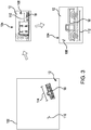
- imaging system 100 acquires second image 104 subsequent to first image 102 with a second field of view 108 that is smaller than a first field of view 110 of first image 102 and, consequently, a second effective resolution 112 that is greater than an effective resolution 114 of first image 102.
- the difference in size between first field of view 110 and second field of view 108 is indicated by the relative separation between the dashed lines and dashed-dotted lines intersecting scene 12.
- Imaging system 100 includes imaging device 106 which has an imaging sensor 116 optically coupled to optics 118 for forming an image on the imaging sensor 116.
- Imaging sensor 116 can be a focal plane array, e.g. a two-dimensional array, or any other suitable type of imaging sensor.
- imaging sensor 116 can be arranged to generate image data using visible wavelength band electromagnetic radiation 120, e.g., blue-red-green light, incident on imaging sensor 116.
- imaging sensor 116 can be arranged to generate image data representative of non-visible wavelength band electromagnetic radiation 122, e.g., short-wavelength infrared band electromagnetic radiation, near-infrared band electromagnetic radiation, mid-range band infrared electromagnetic radiation, and/or thermal band electromagnetic radiation, incident on imaging sensor 116.
- non-visible wavelength band electromagnetic radiation 122 e.g., short-wavelength infrared band electromagnetic radiation, near-infrared band electromagnetic radiation, mid-range band infrared electromagnetic radiation, and/or thermal band electromagnetic radiation
- Imaging sensor 116 is mounted to a platform 124 arranged for one or more of panning, tilting, or zooming the imaging sensor 116 over an imaging area while successive images of the imaging area.
- Platform 124 may include a gimbal 126 configured to rotate the imaging sensor 116 while obtaining successive images, schematically indicated by the curved double-ended arrow above gimbal 126 in Fig. 2 .
- Platform 124 may include a panning element 128 configured to pan electromagnetic radiation acquired from scene 12 over imaging sensor 116, as schematically indicated with the double-ended array below panning element 128 in Fig. 2 .
- Platform 124 may include a zoom element 130 arranged for changing the effective field of view and effective resolution of imagery acquired by imaging sensor 116, schematically indicated by the double-ended arrow above zoom element 130 in Fig. 2 .
- Obtaining the images can include obtaining the successive images included an object of interest, e.g., object 14, 16, 18 (shown in Fig. 1 ), according to recognition of the object in a controller 132 operatively connected to imaging device 106.
- First image 102 is obtained with first field of view 110 and first effective resolution 114.
- effective resolution means the smallest feature in an imaged scene that can be discerned using image data acquired of the scene.
- the effective resolution of an image may be measured in terms of numbers of pixels per unit length of the area being imaged.
- First image 102 is analyzed using a visual attention algorithm resident on controller 132 to identify one or more areas of interest, e.g., vehicle 18, first field of view 110.
- Second image 104 is subsequently obtained for the area of interest with second field of view 108 with a second effective resolution 112, second field of view 108 being smaller than first field of view 110 and second effective resolution 112 being greater than first effective resolution 114.
- Imaging method 200 generally includes obtaining an image with a first field of view and first effective resolution, as shown with box 202.
- the image data is analyzed using a visual attention algorithm, which may be resident in instructions recorded on a non-transitory machine-readable memory of controller 132 (shown in Fig. 2 ), to identify one or more areas of interest in the first field of view, as shown with box 204.
- a subsequent image is then obtained for each area of interest with a second field of view and a second effective resolution, the second field of view being smaller than the first field of view and the second effective resolution being greater than the first effective resolution, as shown with box 206.
- the image acquisition parameters can be adjusted by modifying the positional parameters of the aircraft to which the imaging system is mounted.
- a zoom operation can be effected by positioning the aircraft in closer proximity to the scene; pan and tilt operations can be effected by translating and rotating the aircraft about its axis.
- adjustment of the image acquisition parameters can be achieved by means of combining and imaging system with pan, tilt and zoom capabilities such as that illustrated in Fig. 2 with adjustment of the positional parameters of the aircraft.
- the system comprises more than one aircraft equipped with an imaging system device; upon acquisition and analysis of an initial image by one aircraft, the identified one or more areas of interest in the first field of view can then be imaged by a one or more possibly different aircrafts.
- Imaging system 100 includes image acquisition module 142, imaging system instruction module 144, and visual attention model module 146. Imaging system 100 also includes compression module 148, feature extraction module 150, and decision-making module 152. It is contemplated that each of the modules may be disposed in communication with one and imaging system 106 and/or aircraft 10.
- Image acquisition module 142 is operatively connected with imaging device 106 to obtain image data from a visible wavelength band sensor array, e.g., imaging sensor 116 (shown in Fig. 2 ), for obtaining images based on visible light incident on the imaging device.
- image acquisition module 142 is operatively connected with imaging device 106 to obtain image data from an infrared wavelength band sensor array, e.g., sensor array 116 (shown in Fig. 2 ), such as from incident electromagnetic radiation in one or more of a SWIR wavelength band, a NIR wavelength band, a MIR wavelength band, or a thermal wavelength band.
- Imaging system instruction module 144 is communicative with imaging device 106 and is arranged to generate and issue instructions to imaging device 106.
- the instructions issue by imaging system instruction module 144 may cause imaging device 106 to one or more of pan, tilt and/or zoom with respect to a scene of interest. It is contemplated that the instructions be issued in cooperation with image acquisition module 142 obtaining image data from imaging device 106, subsequent images acquired after issuance of instructions thereby causing change in one or more of pan, tilt, and/or zoom in images image subsequently obtained by imaging device 106 relative to a prior image.
- Visual attention model module 146 is communicative with image acquisition module 142 and imaging system instruction module 144, and is arranged to provide input to imaging system instruction module 144 according to analysis of image data received from image acquisition module 142. Based on the input from the visual attention model module 146, imaging system instruction module 144 may generate the one or more of pan, tilt, and/or zoom instructions for display module 106. The input provided by visual attention model module 146 may be based on the analysis of an image previously acquired by image acquisition module 142. The instructions generated by the visual attention model module 146 are such that each subsequent series of images being acquired has a field of view that is greater than or equal to the field of view of the previously acquired images and has an effective resolution that is greater than or equal to the previously acquired images.
- visual attention model module 146 may cooperate with an air vehicle flight instruction module 154 to issue flight instructions to aircraft 10, aircraft 10 mounting imaging device 106, the flight instructions thereby changing a flight parameter of aircraft 10 (pitch, yaw, altitude, latitude, longitudinal, etc.) modifying subsequent image data obtained by image acquisition module 142 in relation to prior image data obtained by image acquisition module 142.
- a flight parameter of aircraft 10 pitch, yaw, altitude, latitude, longitudinal, etc.
- Compression module 148 and feature extraction module 150 are both communicative with image acquisition module 142 and visual attention model module 146.
- visual attention model module 146 receives raw image data from visual attention model module 146 and analyzes the raw image data.
- feature extraction module 150 first extracts features from image data obtained by image acquisition module 142, communicates the extracted features to visual attention model module 146, which performs analysis on the extracted features.
- visual attentional module 146 receives compression module 148 analyzes on compressed image data from compression 148.
- Compression module 148 may generate a compressed data representation directly from the raw imagery acquired by the image acquisition module 142. In certain embodiments, compression module 148 may generate a compressed data representation of the feature representation extracted by feature extraction module 150 from the raw image data. It is contemplated that compression parameters are selected and applied by compression module 148 according to a type of decision to be made from image data obtained by image acquisition module 142 according the type of decision that has to be made about the scene.
- Decision-making module 152 is communicate with visual attention module 146 and feature extraction module 150 and is arranged to make decisions about the scene based on aggregated information extracted from the image data. The decision about the scene may be based on identification of a type of object in the scene and/or identification of a type of activity taking place in the scene. It is contemplated that decision-making module 152 can issue instructions to cease imaging upon making a determination that sufficient information has been obtained in the subsequent image.
- the proposed system and method would showcase improved accuracy relative to traditional image analysis frameworks due to its ability to zero-in on areas of the data that are of higher relevance to the decision-making task.
- Cost-effective resource allocation is a direct consequence of the approach, since only a subset of locations within the area being surveyed are imaged with a narrow scope. Gains in computational complexity are also incurred due to the fact that only a small fraction of the incoming data is effectively processed.
- the image analysis process is performed by a computer vision system comprising a visual feature extraction module and a sequential analysis module.
- the visual feature extraction module would extract, for each acquired image, features representative of the appearance of the image.
- Such features may comprise features selected a priori including color, texture, edge, human visual saliency, depth and shape descriptors.
- features may be learned in an end-to-end fashion via the use of deep neural networks (NN) including fully connected feedforward networks, multi-layer perceptrons and convolutional neural networks (CNN).
- NN deep neural networks
- CNN convolutional neural networks
- the parameter adjustment is performed within a gradient descent framework, wherein the contribution of each of the parameters to the decision error is computed, and the parameter is adjusted at each step so that its contribution to the error decreases; in this embodiment, the adjustment process can be stopped after a fixed number of iterations or, alternatively, after adjustment of the parameters results in improvement of the decision error by a magnitude smaller than a predetermined threshold.
- the parameters of the non-linear mappings are fixed and the intermediate outputs of each of the layers can be used as visual features.
- the visual features of each of the acquired images are fed to a sequential analysis module in charge of aggregating the features extracted at each step and deciding the image acquisition parameters for the next step.
- This module can take the form of a Recurrent NN or, in some cases, a Long-Short-Term Memory Network (LSTM); other frameworks for time-series analysis including Markov Models and Hidden Markov Models can be used.
- the temporal aggregation module would also determine whether all the information necessary to make a decision is available, in which case it would stop the acquisition process and output a decision regarding the input imagery.
- the parameters of the sequential analysis module can be learned in an offline or training stage with the help of labeled training data.
- the sequential analysis module receives visual features extracted from the image, it analyzes the features and makes a determination about whether more images are required or not. If more images are required, the acquisition parameters of the additional images are determined. If enough images have been acquired, the module issues a decision about the scene being surveyed, the decision being in the form of, for example, the type of objects being present in the scene, the type of action or activity being carried out in the scene, and the like.
- a compression method includes obtaining an image represented by raw image data and analyzing the raw image data to determine content of the image, as shown with box 204.
- An image compression parameter is selected based on the content of the image and a received decision-making task, as shown with boxy 210.
- the image is thereafter compressed based on the selected compression parameter and output as a compressed image.
- the received decision-making task can be, for example, compress with high fidelity features that are conducive to accurate recognition of certain objects in a scene, e.g., people, vehicles, and/or structures. These may include, for example, features descriptive of shapes, color, or texture. In other embodiments, features that are conducive to accurate recognition of certain activities may be compressed with high fidelity.
- Another example of lossy compression includes the application of one or more non-linear mappings that map the raw image from its original high-dimensional space to a lower dimensional space, the parameters of the mapping being adjustable to at least one of the image data and a task-oriented metric corresponding to a received decision-making task such as an object classification or action/activity recognition task.
- a method of imaging a scene can also include analyzing an image in the compressed domain, as shown with box 214, and selecting an area of interest based on the analysis in the compressed domain, as shown with box 216.
- Analysis in the compressed domain can include analyzing the compressed image with a visual attention algorithm to identify one or more areas of interest in the image.
- Subsequent images can be acquired in operation 206 can be obtained for each area of interest, each image having a field of view smaller than the prior image and having greater effective resolution than the prior image.
- instructions can be generated by the imaging system controller, e.g., controller 132, for panning, zooming, and tilting an imaging device, e.g., imaging device 106, carried by an aerial vehicle, e.g., aircraft 10 (shown in Fig. 1 ). It is contemplated that selection of the compression parameter in operation 210 and analysis of the image in the compressed domain in operation 214 be done in real-time with the obtaining of raw image data in operation 202. This allows for the image data collection to be customized according to the content of the imagery as it is received at the aircraft, without the need for off-platform analysis and the implied links and bandwidth to push the information to an off-platform exploitation resource.
- the instructions are autonomously issued to the imaging system to acquire one or more subsequent images, as shown with box 218, and determination made as to whether the content of the image has sufficient information, as shown with decision box 220. Based upon a determination of whether sufficient information is present in the image, imaging can cease, as shown with box 222, or imaging can continue, as shown with arrow 224.
- the task-oriented compression is implemented by means of unsupervised deep learning architectures, which could include Convolutional Auto Encoders (CAEs) and Recurrent Auto Encoders (RAEs) to compress high spatial resolution images, and high spatio-temporal resolution video respectively.
- CAEs Convolutional Auto Encoders
- RAEs Recurrent Auto Encoders
- the task-oriented nature of the proposed compression framework is related to the fact that, although the transmitted and stored data can be represented with much fewer bits than the original data, the decisions made based on the compressed data closely approximate those made with the uncompressed data. This is, as stated, achieved by tuning the compression process relative to the decision-making task at hand.
- the implementation of such deep networks usually takes place in a two-step procedure.
- the parameters of the networks are optimized based on a given objective, which is related to the decision-making task at hand.
- the optimization takes place in an unsupervised manner, where the objective function aims at maximizing reconstruction accuracy of a given input at the output, the output being obtained by decompressing a compressed representation of the input.
- a task-related error term e.g., an object or action classification or recognition error tenn
- the parameters of the nonlinear mappings occurring at the intermediate layers of the autoencoder network are adjusted based on the joint optimization of a reconstruction metric (e.g., how accurately the original data can be recovered from its compressed representation) and a decision-making task such as classification or recognition (e.g., how accurately a given object or action can be identified in the compressed representation of an image or video).
- a reconstruction metric e.g., how accurately the original data can be recovered from its compressed representation
- a decision-making task e.g., how accurately a given object or action can be identified in the compressed representation of an image or video.
- the parameter adjustment is performed within a gradient descent framework, wherein the contribution of each of the parameters to the estimated combined error is computed, and the parameter is adjusted at each step so that its contribution to the error decreases; in this embodiment, the adjustment process can be stopped after a fixed number of iterations or, alternatively, after adjustment of the parameters results in improvement of the combined error by a magnitude smaller than a predetermined threshold.
- the compression architecture optimized in this manner can then be used as the input module to a computer vision (e.g., deep learning or otherwise) pipeline that effectively operates in the compressed domain, such as the one being proposed in the present disclosure.
- imagery and/or video acquired from aerial platforms such as unmanned aerial vehicles (UAV) equipped with an imaging device generally have a relatively wide field of view. Due to its wide-angle nature, imagery from such platforms typically contains a variety of object types including background objects (e.g., vegetation, bodies of water, buildings, roads, etc.) as well as foreground objects, some of which may be of interest (e.g., people, vehicles, weapons, etc.). Consequently, the limited available space for on-board computing resources on such platforms. It is necessary to analyze this imagery to determine imagery of interest from the acquired imagery rapidly, in real-time or in near-real-time, such the acquired imagery can be fully exploited.
- background objects e.g., vegetation, bodies of water, buildings, roads, etc.
- foreground objects e.g., people, vehicles, weapons, etc.
- a sequence of images of an area being surveyed for classification would be acquired in a process that is guided by the visual attention model.
- the process regulates the acquisition of imagery in a sequential manner, with images in each step in the sequence having a narrower scope (i.e., smaller field of view) but higher effective resolution (i.e., larger number of pixels per unit length) than images in previous steps, the narrower scope corresponding to increased discriminability attributes (e.g., more informative image regions) of the imagery relative to the decision-making task at hand.
- the location and nature of each image in the process is determined by aggregated analysis of all of the previously acquired images.
- the proposed active visual attention model would showcase improved accuracy relative to traditional computer vision frameworks due to its ability to zero-in on areas of the data that are of higher relevance to the decision-making task.
- Cost-effective resource allocation is a direct consequence of the approach, since only a subset of locations within the area being surveyed are imaged with a narrow scope.
- Gains in computational complexity are also incurred due to the fact that only a small fraction of the incoming data is effectively processed.
- the system will be able to operate in bandwidth-limited channels with little effect on its decision-making accuracy due to its compression capabilities.
- a UAV may be equipped with an imaging acquisition device with non-adjustable imaging parameters.
- the subsequent images may be acquired by adjusting the positional parameters of the UAV, which would effectively modify the image acquisition parameters.
- one or more secondary UAVs (also with imaging capabilities) would be available to acquire the additional imagery, the parameters of the additional imagery being determined by the location of the secondary UAVs, by the parameters of the image acquisition device in the secondary UAVs, or by a combination of both.
- the proposed model would be enabled by an NN or, preferably, a CNN which would extract features representative of the incoming visual data.
- the extracted features would be fed to an RNN or, in some cases, to a Long-Short-Term Memory Network (LSTM) which would be in charge of aggregating the features extracted at each step and deciding the acquisition parameters for the next step.
- the LSTM would also determine whether all the information necessary to make a decision is available, in which case it would stop the acquisition process and output a decision regarding the input imagery.
- a CAE or RAE would compress the incoming data and feed the compressed data stream to the NN or CNN.
- the visual attention model in this case would operate in the compressed feature space determined by the CAE/RAE.
- the implementation of deep networks usually takes place in a two-step procedure.
- the parameters of the networks are optimized based on a given objective.
- the optimization takes place in an unsupervised manner, where the objective function aims at maximizing reconstruction accuracy of a given input at the output, the output being obtained by decompressing a compressed representation of the input.
- the optimization is supervised in that labels corresponding to the ground truth are required for the training data.
- the optimization is done in the form of backpropagation (across layers for NNs and CNNs, or across layers and time for RNNs and LSTMs) where the output corresponding to a given input is compared to the ground truth and the difference between both is used to adjust the network coefficients.
- backpropagation across layers for NNs and CNNs, or across layers and time for RNNs and LSTMs
- the output corresponding to a given input is compared to the ground truth and the difference between both is used to adjust the network coefficients.
- an input with an unknown label is fed into the network and forward propagated, producing a compressed representation (in the case of a CAE and a RAE), a feature representation (in the case of an NN and a CNN), or a set of sampling parameters and a class label (in the case of an RNN or an LSTM).
- the off-line stage can be down using readily available off-the-shelf processing engines and software.
- processing engines for the off-line stage include the K80 graphical processing units (GPU) accelerator, available from the Nvidia Corporation of Santa Clara, California.
- the on-line and off-line stages can be implemented on the processing engine using deep learning software available such as Caffe, available from the Berkeley Vision and Learning Center of Berkeley, California; Theano, available from the Universite de Montreal of Montreal, Canada; and Digits, available from the Nvidia Corporation of Santa Clara, California.
- an image acquisition method is provided that is guide in real-time. Real-time guidance of the image acquisition process improves the computer vision and visual attention models applied by the image acquisition method. In accordance with certain embodiments, only selected regions within a scene to be imaged are considered in the decision making process. Limiting the selected regions to considered improves resource allocation. Moreover, as only relevant portions of the incoming data are processed, embodiments of the image acquisition methods provided herein are computationally efficient. It is also contemplated that, in embodiments wherein the image acquisition methods operates in the compressed domain, operation in the compressed domain reduces storage and bandwidth requirements of the image acquisition method.
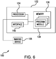
- Imaging system 100 includes a controller 132.
- Controller 132 has a processor 134 and a memory 136.
- Memory 136 is disposed in communication with processor 134 and includes (or may be) a non-transitory, machine-readable medium having instructions recorded thereon that, when read by processor 134, cause controller 132 to executed certain operations, e.g., the above-described operations and associated methods.
- memory 136 includes one or more program modules having the instructions recorded therein, and an interface 140 connects controller 132 with imaging device 106.
- aspects of the present embodiments may be embodied as a system, method or computer program product. Accordingly, aspects of the present embodiments may take the form of an entirely hardware embodiment, an entirely software embodiment (including firmware, resident software, micro-code, etc.) or an embodiment combining software and hardware aspects that may all generally be referred to herein as a "circuit,” “module” or “system.” Furthermore, aspects of the present disclosure may take the form of a computer program product embodied in one or more computer-readable medium(s) having computer-readable program code embodied thereon.
- the computer-readable medium may be a computer-readable signal medium or a computer-readable storage medium.
- a computer-readable storage medium may be, for example, but not limited to, an electronic, magnetic, optical, electromagnetic, infrared, or semiconductor system, apparatus, or device, or any suitable combination of the foregoing.
- a computer-readable storage medium may be any tangible medium that can contain, or store a program for use by or in connection with an instruction execution system, apparatus, or device.
- a computer-readable signal medium may include a propagated data signal with computer-readable program code embodied therein, for example, in baseband or as part of a carrier wave. Such a propagated signal may take any of a variety of forms, including, but not limited to, electro-magnetic, optical, or any suitable combination thereof.
- a computer-readable signal medium may be any computer-readable medium that is not a computer-readable storage medium and that can communicate, propagate, or transport a program for use by or in connection with an instruction execution system, apparatus, or device.
- Program code embodied on a computer-readable medium may be transmitted using any appropriate medium, including but not limited to wireless, wireline, optical fiber cable, RF, etc., or any suitable combination of the foregoing.
- Computer program code for carrying out operations for aspects of the present disclosure may be written in any combination of one or more programming languages, including an object oriented programming language such as Java, Smalltalk, C++ or the like and conventional procedural programming languages, such as the "C" programming language or similar programming languages.
- the program code may execute entirely on the user's computer, partly on the user's computer, as a stand-alone software package, partly on the user's computer and partly on a remote computer or entirely on the remote computer or server.
- the remote computer may be connected to the user's computer through any type of network, including a local area network (LAN) or a wide area network (WAN), or the connection may be made to an external computer (for example, through the Internet using an Internet Service Provider).
- LAN local area network
- WAN wide area network
- Internet Service Provider for example, AT&T, MCI, Sprint, EarthLink, MSN, GTE, etc.
- These computer program instructions may also be stored in a computer-readable medium that can direct a computer, other programmable data processing apparatus, or other devices to function in a particular manner, such that the instructions stored in the computer-readable medium produce an article of manufacture including instructions which implement the function/act specified in the flowchart and/or block diagram block or blocks.
- the computer program instructions may also be loaded onto a computer, other programmable data processing apparatus, or other devices to cause a series of operational steps to be performed on the computer, other programmable apparatus or other devices to produce a computer implemented process such that the instructions which execute on the computer or other programmable apparatus provide processes for implementing the functions/acts specified in a flowchart and/or block diagram block or blocks.
Landscapes
- Engineering & Computer Science (AREA)
- Theoretical Computer Science (AREA)
- Physics & Mathematics (AREA)
- General Physics & Mathematics (AREA)
- Multimedia (AREA)
- Data Mining & Analysis (AREA)
- Signal Processing (AREA)
- General Engineering & Computer Science (AREA)
- Evolutionary Computation (AREA)
- Artificial Intelligence (AREA)
- Computer Vision & Pattern Recognition (AREA)
- Bioinformatics & Computational Biology (AREA)
- Bioinformatics & Cheminformatics (AREA)
- Evolutionary Biology (AREA)
- Life Sciences & Earth Sciences (AREA)
- Remote Sensing (AREA)
- Astronomy & Astrophysics (AREA)
- Computational Linguistics (AREA)
- Computing Systems (AREA)
- Mathematical Physics (AREA)
- Software Systems (AREA)
- Image Analysis (AREA)
- Compression Or Coding Systems Of Tv Signals (AREA)
- Studio Devices (AREA)
Abstract
Description
- The present disclosure relates to imaging, and more particularly to systems and methods of selectively imaging portions of a scene according to prior analysis of the scene. The present disclosure also relates to systems and methods that extract information from the acquired images in order to make at least one decision regarding the nature of the scene to which the acquired images correspond. In some instances, the decision about the nature of the scene may be made by accumulating information extracted from each of the portions of the scene having been imaged.
- Vehicles, such as unmanned aerial vehicles, are commonly used to acquire imagery of a scene of interest, the imagery being subsequently used to make decisions about the nature of the scene (e.g., determine the type of objects present in the scene or the type of activity taking place in the scene). Such vehicles typically include an imaging device with a relatively wide field of view. Due to the wide-angle nature of such imaging devices, a given image from the device may contain a variety of object types including background objects, e.g., vegetation, bodies of water, buildings, roads, etc. as well as foreground objects, some of which may be of interest, e.g., people, vehicles, weapons, etc.. In order to exploit such imagery (e.g., to make decisions based on the acquired imagery,) images must be analyzed, generally by review and classification of the image based upon image content such as by application of a sliding window methodology.
- Sliding window methodologies typically segment a large image into smaller blocks of different sizes, with decisions about individual blocks being made independently (e.g., by assigning an object or an action/activity type to each block independently), the environment for classification is generally highly supervised, since a given image block is usually assumed to be representative of a single class (e.g., the object or objects present or the action/activity taking place in a given image block are assumed to belong to a single category.) Sufficient computational resources are necessary for the attendant computational complexity of the classification algorithms, which typically increase with the number of pixels present in the imagery. That is, the larger the image being processed, the larger the amount of computational resources required to perform the sliding window methodology.
- Such conventional imaging methods have generally been considered satisfactory for their intended purpose. More recently, decision-making models that do not process every pixel in the image, but rather consider only certain locations in it in order to make a decision, have been proposed. The characteristics of the different locations are usually determined based on their saliency attributes relative to the decision-making task at hand. These saliency-based processing methods, however, depend on having static images as inputs and have no control over the image acquisition process. This is a limitation because, as stated, the input images are often wide-angle and provide little visual detail about potential areas of relevance to the decision-making process. Consequently, areas of relevance can often be ignored since not enough visual information about them is available. There is still a need in the art for improved systems and methods for determining saliency in imagery, and use that saliency in order to guide the image acquisition process so that salient regions can be re-imaged with increasing visual detail. The added visual detail with which areas of interest are acquired will result in more robust and accurate decision-making. The present disclosure provides a solution for this need.
- Additionally, traditional algorithms for image analysis operate in the visual domain where they analyze raw image data. In some cases, however, given the large size of the data being considered (e.g., because of the high spatial resolution of the image or the high spatio-temporal resolution of the video being processed) and given limitations in bandwidth or storage capabilities, it may be preferable to compress the data before transmitting it, storing it and processing it. In these cases, it may be beneficial to the computational efficiency of the algorithm to operate in the compressed domain, without the need to first decompress the data to the visual domain. Additionally, while compression algorithms exist which effectively reduce the number of bits required to represent a given stream of data (e.g., JPEG and JPEG 2000 for images, H263 and H264 for videos,) the compression performed is generic in the sense that it is independent of the data being compressed and the task for which the data is intended to be used. It thus may be beneficial to fine tune the parameters of the compression based on the type of data being compressed and the type of analysis being performed on the data.
- An imaging system includes an imaging device, a controller operatively connected to the imaging device, and a non-transitory machine-readable memory disposed in communication with the controller. The memory has instructions recorded on it that, when read by the controller, controller to obtain an image with a first field of view and first effective resolution, analyze the image with a visual attention module to identify one or more areas of interest in the first field of view, and obtain one or more subsequent image for each area of interest. The subsequent image has a field of view that is greater than the first field of view and has an effective resolution that is greater than the first effective resolution. The instructions also cause the controller to make a decision about the scene based on aggregated information extracted from the images.
- In certain embodiments, the instructions can cause the controller to make the decision about the scene based on identification of a type of object in the scene and/or identification of a type of activity taking place in the scene. The instructions can cause the controller to analyze the image using raw image data. The instructions can cause the controller to analyze the image data in the compressed domain. Compression can be done prior to analyzing the image using a visual attention algorithm. It is contemplated that the visual attention algorithm can include a plurality of compression parameters, and that the instructions can cause the controller to select a compression parameter from the plurality of compression parameters according the type of decision that has to be made about the scene.
- In accordance with certain embodiments, the instructions can cause the controller to one or more of pan, zoom, or tilt the imaging apparatus. The instructions can cause the controller to generate one or more of a pan, zoom, and tilt positioning instructions for the imaging device based on the analysis of the image. The instructions can cause the cause the controller to issue the positioning instructions to the imaging systems prior to obtaining the subsequent image. The instructions can cause the controller to adjust a positional parameter of an aerial vehicle carrying the imaging system. The instructions can cause the controller to obtain the second image in real-time with analysis of the prior image.
- It is also contemplated that, in accordance with certain embodiments, the instructions can cause the controller to cease imaging upon making a determination that sufficient information has been obtained in the subsequent image. The imaging device can include a visible wavelength band sensor array for obtaining images based on visible light incident on the imaging device. The imaging device can include an infrared sensor array configured to obtain image data from one or more of a SWIR wavelength band, a NIR wavelength band, a MIR wavelength band, or a thermal wavelength band.
- An imaging method includes obtaining an image with a first field of view and first effective resolution and then analyzing the image with a visual attention algorithm to identify one or more areas of interest in the first field of view. A subsequent image is then obtained for each area of interest with a second field of view and a second effective resolution, the second field of view being smaller than the first field of view and the second effective resolution being greater than the first effective resolution.
- In certain embodiments, analyzing the image can include analyzing raw image data. Analyzing the image can include analyzing compressed domain image data. The method can also include compressing the image prior to analyzing the image with the visual attention algorithm. The subsequent image can be obtained in real-time or near-real-time.
- In accordance with certain embodiments, obtaining the subsequent image can include one or more of panning, zooming, or tilting an imaging apparatus carried by an aerial vehicle. The method can include generating one or more of a pan, zoom, and tilt positioning instructions for an imaging system carried by an unmanned aerial vehicle based on the analysis of the image. The instructions can be issued to the imaging system prior to obtaining the subsequent image.
- It is contemplated that obtaining the image can include sensing electromagnetic radiation within a visible wavelength band. The sensed electromagnetic radiation can be from within an infrared band. The electromagnetic radiation can be from a short-wavelength infrared band, a near-infrared band, a mid-infrared band, and/or a thermal wavelength band. Once the visual attention module has determined that sufficient information is present in the image data, instructions can be issued to the imaging system to cease imaging.
- An imaging system includes an imaging device, a controller operatively connected to the imaging device, and a non-transitory machine-readable memory disposed in communication with the controller. The memory has instructions recorded on it that, when read by the controller, cause the controller to obtain an image represented by raw image data, analyze the raw image data to determine content of the image, and adjust at least one image compression parameter in a compression algorithm based on the content of the image and a received decision-making task to produce a modified compression algorithm. The instructions also cause the controller to compress the image using the modified compression algorithm and output the image as a compressed image.
- In certain embodiments, the instructions can cause the controller to identify one or more areas of interest in the image using a visual attention module. The instructions can cause the controller to obtain a subsequent image for each area of interest with a field of view smaller than a field of view of the prior image and having an effective resolution greater than an effective resolution of the prior image.
- In accordance with certain embodiments, the modified compression algorithm can preserve with high fidelity features in the raw image data that are relevant to the decision-making task. The compression algorithm can include an autoencoder, and the autoencoder parameter adjustment can be done in a training stage, such as an off-line training. It is contemplated that the training stage can include instructions which cause the controller to adjust the parameters of the autoencoder based on the optimization of at least one of a reconstruction metric and a classification metric.
- A method of compressing an image includes obtaining an image represented by raw image data and analyzing the raw image data to determine content of the image. An image compression parameter is selected based on the content of the image and a received decision-making task, the image compressed using the selected compression parameter, and the image output thereafter as a compressed image.
- In certain embodiments, the compressed image data can be analyzed with a visual attention algorithm to identify one or more areas of interest in the image without the need to decompress the image. A subsequent image can be obtained for each area of interest having a field of view smaller than the prior image and having greater effective resolution than the prior image.
- It is contemplated that compressing the raw image data can include applying one or more of run-length encoding, predictive coding, entropy encoding, deflation, chain coding, and/or application of an adaptive dictionary algorithm to the raw image data. It is also contemplated that compressing the raw image data can include one or more of application of color space reduction, chroma sampling, transform coding, and/or fractal compression technique to the raw image data. It is also contemplated that compressing the raw image data can include application of one or more non-linear mappings that map the raw image from its original high-dimensional space a lower dimensional space, the parameters of the mapping being adjustable to at least one of the image data and a task-oriented metric corresponding to a received decision-making task such as an object classification or action/activity recognition task.
- An imaging system includes an imaging device, a controller operatively connected to the imaging device, and a non-transitory machine-readable memory disposed in communication with the controller. The memory has instructions recorded on it that, when read by the controller, cause the controller to obtain an image represented by raw image data, analyze the raw image data to determine content of the image, and select an image compression parameter based on the content of the image and a received decision-making task. The instructions further cause the controller to analyze the image in the compressed domain, select one or more areas of interest within the image from the compressed image, and acquire subsequent images including the areas of interest selected from the compressed image.
- A method of imaging a scene includes obtaining an image represented by raw image data; and analyzing the raw image data to determine content of the image. An image compression parameter is selected based on the content of the image and a received decision-makingtask. The image is analyzed in the compressed domain, and one or more areas of interest are selected within the image from the compressed image. One or more subsequent images are thereafter acquired including the areas of interest selected from the compressed image. In certain embodiments, a visual attention algorithm is applied to the raw image data. In accordance with certain embodiments, a visual attention algorithm is applied to the compressed image to analyze the image in the compressed domain.
- These and other features of the systems and methods of the subject disclosure will become more readily apparent to those skilled in the art from the following detailed description of the preferred embodiments taken in conjunction with the drawings.
- So that those skilled in the art to which the subject disclosure appertains will readily understand how to make and use the devices and methods of the subject disclosure without undue experimentation, embodiments thereof will be described in detail herein below with reference to certain figures, wherein:
-
Fig. 1 is a schematic view of an exemplary embodiment of an imaging method in accordance with the present disclosure, showing an imaging system carried by an aircraft acquiring an image and a subsequent image of a scene based on a feature in the scene; -
Fig. 2 is a schematic view of the imaging system ofFig. 1 , showing elements of the system for tilting, panning, and zooming an imaging device of the imaging system; -
Fig. 3 is a schematic view of the image and subsequent image ofFig. 1 , showing a feature present in the scene appearing with in the subsequent image with a smaller field of view and greater effective resolution than in the prior image; -
Fig. 4 is a block diagram of a method of imaging a scene associated with the imaging device ofFig. 1 , showing analysis of the raw image data for selection of a compression parameter and analysis of the mage in the compressed domain; -
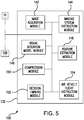
Fig. 5 is a schematic block diagram of an exemplary embodiment of the imaging system ofFig. 1 , showing modules for imaging a scene using the imaging system; and -
Fig. 6 is a schematic diagram view of an exemplary embodiment of the imaging system ofFig. 1 , showing elements containing instruction for imaging a scene using the imaging system. - Reference will now be made to the drawings wherein like reference numerals identify similar structural features or aspects of the subject disclosure. For purposes of explanation and illustration, and not limitation, a partial view of an exemplary embodiment of an imaging system and associated method, in accordance with the disclosure is shown in
Fig. 1 and is designated generally byreference character 100. Other embodiments of image acquisition methods in accordance with the disclosure, or aspects thereof, are provided inFigs. 2-6 , as will be described. The systems and methods described herein can be used to improve imaging, such as long range oblique imaging for aircraft and spacecraft imaging the terrestrial scenes. -
Imaging system 100 is mounted to anaircraft 10, which may be an unmanned aerial vehicle (UAV). A method of obtaining image data usingimaging system 100 includes obtaining afirst image 102 and a subsequentsecond image 104 of ascene 106 with one or more features, e.g.,tree 14,structure 16, andvehicle 18.First image 102 and subsequentsecond image 104 are obtained using animaging device 106, shown inFig. 2 , which is configured and adapted for obtaining images of a scene with different field of views and different effective resolutions. Usingimaging device 106,imaging system 100 acquiressecond image 104 subsequent tofirst image 102 with a second field ofview 108 that is smaller than a first field ofview 110 offirst image 102 and, consequently, a secondeffective resolution 112 that is greater than aneffective resolution 114 offirst image 102. The difference in size between first field ofview 110 and second field ofview 108 is indicated by the relative separation between the dashed lines and dashed-dottedlines intersecting scene 12. - With reference now to
Fig. 2 ,imaging system 100 is shown.Imaging system 100 includesimaging device 106 which has animaging sensor 116 optically coupled to optics 118 for forming an image on theimaging sensor 116.Imaging sensor 116 can be a focal plane array, e.g. a two-dimensional array, or any other suitable type of imaging sensor. In certain embodiments,imaging sensor 116 can be arranged to generate image data using visible wavelength bandelectromagnetic radiation 120, e.g., blue-red-green light, incident onimaging sensor 116. In accordance with certain embodiments,imaging sensor 116 can be arranged to generate image data representative of non-visible wavelength bandelectromagnetic radiation 122, e.g., short-wavelength infrared band electromagnetic radiation, near-infrared band electromagnetic radiation, mid-range band infrared electromagnetic radiation, and/or thermal band electromagnetic radiation, incident onimaging sensor 116. -
Imaging sensor 116 is mounted to aplatform 124 arranged for one or more of panning, tilting, or zooming theimaging sensor 116 over an imaging area while successive images of the imaging area.Platform 124 may include agimbal 126 configured to rotate theimaging sensor 116 while obtaining successive images, schematically indicated by the curved double-ended arrow abovegimbal 126 inFig. 2 .Platform 124 may include apanning element 128 configured to pan electromagnetic radiation acquired fromscene 12 overimaging sensor 116, as schematically indicated with the double-ended array below panningelement 128 inFig. 2 .Platform 124 may include azoom element 130 arranged for changing the effective field of view and effective resolution of imagery acquired byimaging sensor 116, schematically indicated by the double-ended arrow abovezoom element 130 inFig. 2 . Obtaining the images can include obtaining the successive images included an object of interest, e.g., object 14, 16, 18 (shown inFig. 1 ), according to recognition of the object in acontroller 132 operatively connected toimaging device 106. - With reference now to
Fig. 3 , images obtained withimaging system 100 are shown.First image 102 is obtained with first field ofview 110 and firsteffective resolution 114. For purposes of the present disclosure, effective resolution means the smallest feature in an imaged scene that can be discerned using image data acquired of the scene. In one embodiment, the effective resolution of an image may be measured in terms of numbers of pixels per unit length of the area being imaged.First image 102 is analyzed using a visual attention algorithm resident oncontroller 132 to identify one or more areas of interest, e.g.,vehicle 18, first field ofview 110.Second image 104 is subsequently obtained for the area of interest with second field ofview 108 with a secondeffective resolution 112, second field ofview 108 being smaller than first field ofview 110 and secondeffective resolution 112 being greater than firsteffective resolution 114. - With reference to
Fig. 4 , animaging method 200 is shown.Imaging method 200 generally includes obtaining an image with a first field of view and first effective resolution, as shown withbox 202. The image data is analyzed using a visual attention algorithm, which may be resident in instructions recorded on a non-transitory machine-readable memory of controller 132 (shown inFig. 2 ), to identify one or more areas of interest in the first field of view, as shown withbox 204. A subsequent image is then obtained for each area of interest with a second field of view and a second effective resolution, the second field of view being smaller than the first field of view and the second effective resolution being greater than the first effective resolution, as shown withbox 206. - In an alternative embodiment not illustrated in the drawings, and possibly in the absence of an imaging system with panning, tilting and zooming capabilities, it will be apparent for those familiar in the art that the image acquisition parameters can be adjusted by modifying the positional parameters of the aircraft to which the imaging system is mounted. Specifically, a zoom operation can be effected by positioning the aircraft in closer proximity to the scene; pan and tilt operations can be effected by translating and rotating the aircraft about its axis. In yet another embodiment, adjustment of the image acquisition parameters can be achieved by means of combining and imaging system with pan, tilt and zoom capabilities such as that illustrated in
Fig. 2 with adjustment of the positional parameters of the aircraft. In one embodiment, the system comprises more than one aircraft equipped with an imaging system device; upon acquisition and analysis of an initial image by one aircraft, the identified one or more areas of interest in the first field of view can then be imaged by a one or more possibly different aircrafts. - With reference to
Fig. 5 , modules ofimaging system 100 are shown according to an exemplary embodiment.Imaging system 100 includesimage acquisition module 142, imagingsystem instruction module 144, and visualattention model module 146.Imaging system 100 also includescompression module 148,feature extraction module 150, and decision-making module 152. It is contemplated that each of the modules may be disposed in communication with one andimaging system 106 and/oraircraft 10. -
Image acquisition module 142 is operatively connected withimaging device 106 to obtain image data from a visible wavelength band sensor array, e.g., imaging sensor 116 (shown inFig. 2 ), for obtaining images based on visible light incident on the imaging device. In some instances,image acquisition module 142 is operatively connected withimaging device 106 to obtain image data from an infrared wavelength band sensor array, e.g., sensor array 116 (shown inFig. 2 ), such as from incident electromagnetic radiation in one or more of a SWIR wavelength band, a NIR wavelength band, a MIR wavelength band, or a thermal wavelength band. - Imaging
system instruction module 144 is communicative withimaging device 106 and is arranged to generate and issue instructions toimaging device 106. The instructions issue by imagingsystem instruction module 144 may causeimaging device 106 to one or more of pan, tilt and/or zoom with respect to a scene of interest. It is contemplated that the instructions be issued in cooperation withimage acquisition module 142 obtaining image data fromimaging device 106, subsequent images acquired after issuance of instructions thereby causing change in one or more of pan, tilt, and/or zoom in images image subsequently obtained byimaging device 106 relative to a prior image. - Visual
attention model module 146 is communicative withimage acquisition module 142 and imagingsystem instruction module 144, and is arranged to provide input to imagingsystem instruction module 144 according to analysis of image data received fromimage acquisition module 142. Based on the input from the visualattention model module 146, imagingsystem instruction module 144 may generate the one or more of pan, tilt, and/or zoom instructions fordisplay module 106. The input provided by visualattention model module 146 may be based on the analysis of an image previously acquired byimage acquisition module 142. The instructions generated by the visualattention model module 146 are such that each subsequent series of images being acquired has a field of view that is greater than or equal to the field of view of the previously acquired images and has an effective resolution that is greater than or equal to the previously acquired images. - In contemplated embodiments, visual
attention model module 146 may cooperate with an air vehicleflight instruction module 154 to issue flight instructions toaircraft 10,aircraft 10 mountingimaging device 106, the flight instructions thereby changing a flight parameter of aircraft 10 (pitch, yaw, altitude, latitude, longitudinal, etc.) modifying subsequent image data obtained byimage acquisition module 142 in relation to prior image data obtained byimage acquisition module 142. -
Compression module 148 andfeature extraction module 150 are both communicative withimage acquisition module 142 and visualattention model module 146. In certain embodiments, visualattention model module 146 receives raw image data from visualattention model module 146 and analyzes the raw image data. In accordance with certain embodiments,feature extraction module 150 first extracts features from image data obtained byimage acquisition module 142, communicates the extracted features to visualattention model module 146, which performs analysis on the extracted features. In accordance with certain embodiments, visualattentional module 146 receivescompression module 148 analyzes on compressed image data fromcompression 148. -
Compression module 148 may generate a compressed data representation directly from the raw imagery acquired by theimage acquisition module 142. In certain embodiments,compression module 148 may generate a compressed data representation of the feature representation extracted byfeature extraction module 150 from the raw image data. It is contemplated that compression parameters are selected and applied bycompression module 148 according to a type of decision to be made from image data obtained byimage acquisition module 142 according the type of decision that has to be made about the scene. - Decision-making
module 152 is communicate withvisual attention module 146 andfeature extraction module 150 and is arranged to make decisions about the scene based on aggregated information extracted from the image data. The decision about the scene may be based on identification of a type of object in the scene and/or identification of a type of activity taking place in the scene. It is contemplated that decision-making module 152 can issue instructions to cease imaging upon making a determination that sufficient information has been obtained in the subsequent image. - The proposed system and method would showcase improved accuracy relative to traditional image analysis frameworks due to its ability to zero-in on areas of the data that are of higher relevance to the decision-making task. Cost-effective resource allocation is a direct consequence of the approach, since only a subset of locations within the area being surveyed are imaged with a narrow scope. Gains in computational complexity are also incurred due to the fact that only a small fraction of the incoming data is effectively processed.
- In one embodiment, the image analysis process is performed by a computer vision system comprising a visual feature extraction module and a sequential analysis module. The visual feature extraction module would extract, for each acquired image, features representative of the appearance of the image. Such features may comprise features selected a priori including color, texture, edge, human visual saliency, depth and shape descriptors. Alternatively, features may be learned in an end-to-end fashion via the use of deep neural networks (NN) including fully connected feedforward networks, multi-layer perceptrons and convolutional neural networks (CNN). These networks process the incoming visual data through a series of layers that effectively perform non-linear mappings of the input data. The output of each intermediate layer can be interpreted as a visual feature. The advantage of these types of visual features is that they are optimized to the decision-making task for which the network is being used. This is because the parameters of the non-linear activation functions are optimized in an offline or training stage where data with known corresponding ground truth is passed through the network to obtain a decision. The decision issued by the network is compared with the decision corresponding to the ground truth, and the difference between both (or the decision error) is used to adjust the parameters of the intermediate non-linear mappings. This process is repeated for a large number of training samples until convergence on the parameters of the non-linear mappings is achieved. In one embodiment, the parameter adjustment is performed within a gradient descent framework, wherein the contribution of each of the parameters to the decision error is computed, and the parameter is adjusted at each step so that its contribution to the error decreases; in this embodiment, the adjustment process can be stopped after a fixed number of iterations or, alternatively, after adjustment of the parameters results in improvement of the decision error by a magnitude smaller than a predetermined threshold. When the system is deployed, the parameters of the non-linear mappings are fixed and the intermediate outputs of each of the layers can be used as visual features.
- Once extracted, the visual features of each of the acquired images are fed to a sequential analysis module in charge of aggregating the features extracted at each step and deciding the image acquisition parameters for the next step. This module can take the form of a Recurrent NN or, in some cases, a Long-Short-Term Memory Network (LSTM); other frameworks for time-series analysis including Markov Models and Hidden Markov Models can be used. The temporal aggregation module would also determine whether all the information necessary to make a decision is available, in which case it would stop the acquisition process and output a decision regarding the input imagery. As in the case of the deep visual feature extraction module, the parameters of the sequential analysis module can be learned in an offline or training stage with the help of labeled training data. As the sequential analysis module receives visual features extracted from the image, it analyzes the features and makes a determination about whether more images are required or not. If more images are required, the acquisition parameters of the additional images are determined. If enough images have been acquired, the module issues a decision about the scene being surveyed, the decision being in the form of, for example, the type of objects being present in the scene, the type of action or activity being carried out in the scene, and the like.
- As indicated by
bracket 208, a compression method includes obtaining an image represented by raw image data and analyzing the raw image data to determine content of the image, as shown withbox 204. An image compression parameter is selected based on the content of the image and a received decision-making task, as shown with boxy 210. The image is thereafter compressed based on the selected compression parameter and output as a compressed image. The received decision-making task can be, for example, compress with high fidelity features that are conducive to accurate recognition of certain objects in a scene, e.g., people, vehicles, and/or structures. These may include, for example, features descriptive of shapes, color, or texture. In other embodiments, features that are conducive to accurate recognition of certain activities may be compressed with high fidelity. These may include, for example, features descriptive of motion patterns. Another example of lossy compression includes the application of one or more non-linear mappings that map the raw image from its original high-dimensional space to a lower dimensional space, the parameters of the mapping being adjustable to at least one of the image data and a task-oriented metric corresponding to a received decision-making task such as an object classification or action/activity recognition task. - As indicated with
bracket 212, a method of imaging a scene can also include analyzing an image in the compressed domain, as shown withbox 214, and selecting an area of interest based on the analysis in the compressed domain, as shown withbox 216. Analysis in the compressed domain can include analyzing the compressed image with a visual attention algorithm to identify one or more areas of interest in the image. Subsequent images can be acquired inoperation 206 can be obtained for each area of interest, each image having a field of view smaller than the prior image and having greater effective resolution than the prior image. - Once an object of interest is identified in
operation 216 instructions can be generated by the imaging system controller, e.g.,controller 132, for panning, zooming, and tilting an imaging device, e.g.,imaging device 106, carried by an aerial vehicle, e.g., aircraft 10 (shown inFig. 1 ). It is contemplated that selection of the compression parameter inoperation 210 and analysis of the image in the compressed domain inoperation 214 be done in real-time with the obtaining of raw image data inoperation 202. This allows for the image data collection to be customized according to the content of the imagery as it is received at the aircraft, without the need for off-platform analysis and the implied links and bandwidth to push the information to an off-platform exploitation resource. Instead, the instructions are autonomously issued to the imaging system to acquire one or more subsequent images, as shown withbox 218, and determination made as to whether the content of the image has sufficient information, as shown withdecision box 220. Based upon a determination of whether sufficient information is present in the image, imaging can cease, as shown withbox 222, or imaging can continue, as shown witharrow 224. - In one embodiment, the task-oriented compression is implemented by means of unsupervised deep learning architectures, which could include Convolutional Auto Encoders (CAEs) and Recurrent Auto Encoders (RAEs) to compress high spatial resolution images, and high spatio-temporal resolution video respectively. The task-oriented nature of the proposed compression framework is related to the fact that, although the transmitted and stored data can be represented with much fewer bits than the original data, the decisions made based on the compressed data closely approximate those made with the uncompressed data. This is, as stated, achieved by tuning the compression process relative to the decision-making task at hand.
- The implementation of such deep networks usually takes place in a two-step procedure. In the offline or training stage, the parameters of the networks are optimized based on a given objective, which is related to the decision-making task at hand. In the case of CAEs and RAEs, the optimization takes place in an unsupervised manner, where the objective function aims at maximizing reconstruction accuracy of a given input at the output, the output being obtained by decompressing a compressed representation of the input. In the proposed method, in addition to a reconstruction error term, a task-related error term (e.g., an object or action classification or recognition error tenn) is also considered in the optimization of the autoencoder. This means that the parameters of the nonlinear mappings occurring at the intermediate layers of the autoencoder network are adjusted based on the joint optimization of a reconstruction metric (e.g., how accurately the original data can be recovered from its compressed representation) and a decision-making task such as classification or recognition (e.g., how accurately a given object or action can be identified in the compressed representation of an image or video). In one embodiment, the parameter adjustment is performed within a gradient descent framework, wherein the contribution of each of the parameters to the estimated combined error is computed, and the parameter is adjusted at each step so that its contribution to the error decreases; in this embodiment, the adjustment process can be stopped after a fixed number of iterations or, alternatively, after adjustment of the parameters results in improvement of the combined error by a magnitude smaller than a predetermined threshold. This results in intermediate representations that more efficiently maintain the information that is relevant to the task. In other words, while the recovered data may not necessarily faithfully represent the original data, the information contained therein is sufficient to carry out the decision-making task robustly and accurately. The compression architecture optimized in this manner can then be used as the input module to a computer vision (e.g., deep learning or otherwise) pipeline that effectively operates in the compressed domain, such as the one being proposed in the present disclosure.
- As will be appreciated by those of skill in the art in view of the present disclosure, application of automated reasoning to visual data, and particularly deep learning (DL) automated reasoning frameworks, can require considerable computing resources. By way of illustration, imagery and/or video acquired from aerial platforms such as unmanned aerial vehicles (UAV) equipped with an imaging device generally have a relatively wide field of view. Due to its wide-angle nature, imagery from such platforms typically contains a variety of object types including background objects (e.g., vegetation, bodies of water, buildings, roads, etc.) as well as foreground objects, some of which may be of interest (e.g., people, vehicles, weapons, etc.). Consequently, the limited available space for on-board computing resources on such platforms. It is necessary to analyze this imagery to determine imagery of interest from the acquired imagery rapidly, in real-time or in near-real-time, such the acquired imagery can be fully exploited.
- One approach to analyzing such imagery is through a sliding window approach, where an image analyzed by segmenting the image into smaller blocks of different sizes, which are thereafter assigned categories independently. Consequently, the computational complexity of said algorithms scales with the number of pixels in the incoming imagery. The motivation behind this modus operandi stems from the requirement of most computer vision algorithms to operate in highly supervised environments in which a given image is representative of a single class only, that is, where an object or objects present in a given image belong to a single category; clearly, this requirement is more easily satisfied by images covering small fields of view since this limits the possible range of labels of objects present in the image.
- In order to overcome these limitations, visual attention models which learn to process information only at locations of the incoming imagery that are relevant to the decision-making task at hand, have recently been successfully integrated with computer vision algorithms. The benefits of these approaches are improved computational efficiency as well as added robustness to multiple class labels per image. Their main limitation, however, lies in the fact that they are passive in that they operate on fixed imagery and have no influence on the image acquisition process. We propose to bring visual attention models and computer vision algorithms into the image acquisition loop in order to guide the image capture process in real time in a framework which we denote active visual attention models.
- According to the proposed framework, a sequence of images of an area being surveyed for classification (e.g., determining whether there is a threat or not) would be acquired in a process that is guided by the visual attention model. The process regulates the acquisition of imagery in a sequential manner, with images in each step in the sequence having a narrower scope (i.e., smaller field of view) but higher effective resolution (i.e., larger number of pixels per unit length) than images in previous steps, the narrower scope corresponding to increased discriminability attributes (e.g., more informative image regions) of the imagery relative to the decision-making task at hand. The location and nature of each image in the process is determined by aggregated analysis of all of the previously acquired images. This approach results in highly efficient resource utilization since there is no need to image up-close every location within the area being surveyed. The process would stop when the model determines enough information has been sequentially aggregated from the area being surveyed. Since the acquisition, transmission and processing of the relevant imagery may be effected in systems with bandwidth limitations, we also propose the use of actionable compression architectures relying on unsupervised Convolutional Auto Encoders (CAEs) and Recurrent Auto Encoders (RAEs) to compress high spatial resolution images and high spatio-temporal resolution video respectively. The actionable nature of the proposed compression framework is related to the fact that, although the transmitted and stored data can be represented with much fewer bits than the original data, the decisions made based on the compressed data closely approximate those made with the uncompressed data.
- The proposed active visual attention model would showcase improved accuracy relative to traditional computer vision frameworks due to its ability to zero-in on areas of the data that are of higher relevance to the decision-making task. Cost-effective resource allocation is a direct consequence of the approach, since only a subset of locations within the area being surveyed are imaged with a narrow scope. Gains in computational complexity are also incurred due to the fact that only a small fraction of the incoming data is effectively processed. Lastly, the system will be able to operate in bandwidth-limited channels with little effect on its decision-making accuracy due to its compression capabilities.
- To illustrate the benefits of the proposed technology, consider the case of a UAV equipped with an imaging device having pan, tilt and zoom (PTZ) capabilities. In this scenario, and in order to perform analysis of imagery of an area being surveyed, an initial image is acquired at the widest focal setting possible (corresponding to the widest field of view). Visual attention analysis on the acquired image would yield a candidate location (or set of candidate locations) for further, more detailed analysis. Additional, narrower scope (e.g., more tightly framed) imagery would then be acquired of each of the identified candidate locations by adjusting the PTZ parameters, and the visual attention analysis would be performed again on each of the images. The process would continue until the model decides that there are no more regions to process, and a decision would be made regarding the nature of the imagery acquired by sequentially aggregating the information extracted at each step. Note that there are slight implementational variations that can be enabled under the proposed framework. In one alternative scenario, a UAV may be equipped with an imaging acquisition device with non-adjustable imaging parameters. In this case, the subsequent images may be acquired by adjusting the positional parameters of the UAV, which would effectively modify the image acquisition parameters. In another scenario, in addition to a primary UAV, which again may be equipped with an imaging acquisition device with non-adjustable imaging parameters, one or more secondary UAVs (also with imaging capabilities) would be available to acquire the additional imagery, the parameters of the additional imagery being determined by the location of the secondary UAVs, by the parameters of the image acquisition device in the secondary UAVs, or by a combination of both.
- The proposed model would be enabled by an NN or, preferably, a CNN which would extract features representative of the incoming visual data. The extracted features would be fed to an RNN or, in some cases, to a Long-Short-Term Memory Network (LSTM) which would be in charge of aggregating the features extracted at each step and deciding the acquisition parameters for the next step. The LSTM would also determine whether all the information necessary to make a decision is available, in which case it would stop the acquisition process and output a decision regarding the input imagery. Additionally, and optionally, in cases where data compression is required, a CAE or RAE would compress the incoming data and feed the compressed data stream to the NN or CNN. The visual attention model in this case would operate in the compressed feature space determined by the CAE/RAE.
- The implementation of deep networks usually takes place in a two-step procedure. In the offline or training stage, the parameters of the networks are optimized based on a given objective. In the case of CAEs and RAEs, the optimization takes place in an unsupervised manner, where the objective function aims at maximizing reconstruction accuracy of a given input at the output, the output being obtained by decompressing a compressed representation of the input. For NNs, CNNs, RNNs and LSTMs, the optimization is supervised in that labels corresponding to the ground truth are required for the training data. The optimization is done in the form of backpropagation (across layers for NNs and CNNs, or across layers and time for RNNs and LSTMs) where the output corresponding to a given input is compared to the ground truth and the difference between both is used to adjust the network coefficients. In the online or inference stage, an input with an unknown label is fed into the network and forward propagated, producing a compressed representation (in the case of a CAE and a RAE), a feature representation (in the case of an NN and a CNN), or a set of sampling parameters and a class label (in the case of an RNN or an LSTM). Advantageously, the off-line stage can be down using readily available off-the-shelf processing engines and software. Examples of suitable processing engines for the off-line stage include the K80 graphical processing units (GPU) accelerator, available from the Nvidia Corporation of Santa Clara, California. The on-line and off-line stages can be implemented on the processing engine using deep learning software available such as Caffe, available from the Berkeley Vision and Learning Center of Berkeley, California; Theano, available from the Universite de Montreal of Montreal, Canada; and Digits, available from the Nvidia Corporation of Santa Clara, California.
- In certain embodiments described herein, an image acquisition method is provided that is guide in real-time. Real-time guidance of the image acquisition process improves the computer vision and visual attention models applied by the image acquisition method. In accordance with certain embodiments, only selected regions within a scene to be imaged are considered in the decision making process. Limiting the selected regions to considered improves resource allocation. Moreover, as only relevant portions of the incoming data are processed, embodiments of the image acquisition methods provided herein are computationally efficient. It is also contemplated that, in embodiments wherein the image acquisition methods operates in the compressed domain, operation in the compressed domain reduces storage and bandwidth requirements of the image acquisition method.
- With reference to
Fig. 6 , an exemplary embodiment of animaging system 100 is shown.Imaging system 100 includes acontroller 132.Controller 132 has aprocessor 134 and amemory 136.Memory 136 is disposed in communication withprocessor 134 and includes (or may be) a non-transitory, machine-readable medium having instructions recorded thereon that, when read byprocessor 134,cause controller 132 to executed certain operations, e.g., the above-described operations and associated methods. In the illustratedexemplary embodiment memory 136 includes one or more program modules having the instructions recorded therein, and aninterface 140 connectscontroller 132 withimaging device 106. - As will be appreciated by those skilled in the art, aspects of the present embodiments may be embodied as a system, method or computer program product. Accordingly, aspects of the present embodiments may take the form of an entirely hardware embodiment, an entirely software embodiment (including firmware, resident software, micro-code, etc.) or an embodiment combining software and hardware aspects that may all generally be referred to herein as a "circuit," "module" or "system." Furthermore, aspects of the present disclosure may take the form of a computer program product embodied in one or more computer-readable medium(s) having computer-readable program code embodied thereon.
- Any combination of one or more computer-readable medium(s) may be utilized. The computer-readable medium may be a computer-readable signal medium or a computer-readable storage medium. A computer-readable storage medium may be, for example, but not limited to, an electronic, magnetic, optical, electromagnetic, infrared, or semiconductor system, apparatus, or device, or any suitable combination of the foregoing. More specific examples (a non-exhaustive list) of the computer-readable storage medium would include the following: an electrical connection having one or more wires, a portable computer diskette, a hard disk, a random access memory (RAM), a read-only memory (ROM), an erasable programmable read-only memory (EPROM or Flash memory), an optical fiber, a portable compact disc read-only memory (CD-ROM), an optical storage device, a magnetic storage device, or any suitable combination of the foregoing. In the context of this document, a computer-readable storage medium may be any tangible medium that can contain, or store a program for use by or in connection with an instruction execution system, apparatus, or device.
- A computer-readable signal medium may include a propagated data signal with computer-readable program code embodied therein, for example, in baseband or as part of a carrier wave. Such a propagated signal may take any of a variety of forms, including, but not limited to, electro-magnetic, optical, or any suitable combination thereof. A computer-readable signal medium may be any computer-readable medium that is not a computer-readable storage medium and that can communicate, propagate, or transport a program for use by or in connection with an instruction execution system, apparatus, or device.
- Program code embodied on a computer-readable medium may be transmitted using any appropriate medium, including but not limited to wireless, wireline, optical fiber cable, RF, etc., or any suitable combination of the foregoing.
- Computer program code for carrying out operations for aspects of the present disclosure may be written in any combination of one or more programming languages, including an object oriented programming language such as Java, Smalltalk, C++ or the like and conventional procedural programming languages, such as the "C" programming language or similar programming languages. The program code may execute entirely on the user's computer, partly on the user's computer, as a stand-alone software package, partly on the user's computer and partly on a remote computer or entirely on the remote computer or server. In the latter scenario, the remote computer may be connected to the user's computer through any type of network, including a local area network (LAN) or a wide area network (WAN), or the connection may be made to an external computer (for example, through the Internet using an Internet Service Provider).
- Aspects of the present disclosure are described above with reference to flowchart illustrations and/or block diagrams of methods, apparatus (systems) and computer program products according to embodiments of the embodiments. It will be understood that each block of the flowchart illustrations and/or block diagrams, and combinations of blocks in the flowchart illustrations and/or block diagrams, can be implemented by computer program instructions. These computer program instructions may be provided to a processor of a general purpose computer, special purpose computer, or other programmable data processing apparatus to produce a machine, such that the instructions, which execute via the processor of the computer or other programmable data processing apparatus, create means for implementing the functions/acts specified in the flowchart and/or block diagram block or blocks.
- These computer program instructions may also be stored in a computer-readable medium that can direct a computer, other programmable data processing apparatus, or other devices to function in a particular manner, such that the instructions stored in the computer-readable medium produce an article of manufacture including instructions which implement the function/act specified in the flowchart and/or block diagram block or blocks.
- The computer program instructions may also be loaded onto a computer, other programmable data processing apparatus, or other devices to cause a series of operational steps to be performed on the computer, other programmable apparatus or other devices to produce a computer implemented process such that the instructions which execute on the computer or other programmable apparatus provide processes for implementing the functions/acts specified in a flowchart and/or block diagram block or blocks.
- The methods and systems of the present disclosure, as described above and shown in the drawings, provide for image acquisition methods with superior properties including real-time guidance to the image acquisition method. While the apparatus and methods of the subject disclosure have been shown and described with reference to preferred embodiments, those skilled in the art will readily appreciate that changes and/or modifications may be made thereto without departing from the scope of the subject disclosure.
Claims (15)
- An image analysis system (100), comprising:an imaging device (106);a controller (132) operatively connected to the imaging device; anda non-transitory machine-readable memory disposed in communication with the controller and having instructions recorded thereon that, when read by the controller, cause the controller to:obtain an image with a first field of view and first effective resolution;analyze the image with a visual attention module to identify one or more areas of interest in the first field of view;obtain one or more subsequent images for each area of interest each with a possible different field of view and, and each of the associated effective resolutions is greater than the first effective resolution; andmaking a decision about the scene by aggregating information extracted from the obtained images.
- The system as recited in claim 1, wherein the instructions cause the controller to make the decision about the scene based on (a) identification of a type of object in the scene, and (b) identification of a type of activity taking place in the scene.
- The system as recited in claim 1, wherein analyzing the image comprises analyzing raw image data.
- The system as recited in claim 1, wherein analyzing the image comprises analyzing compressed domain image data.
- The system as recited in claim 4, wherein the instructions further cause the controller to compresses the image prior to analyzing the image with the visual attention algorithm.
- The system as recited in claim 5, wherein the visual attention algorithm includes a plurality of compression parameters, wherein the instructions cause the controller to select a compression parameter from the plurality of compression parameters according to the type of a decision that has to be made about the scene.
- The system as recited in claim 1, wherein instructions further cause the controller to one or more of pan, zoom, or tilt the imaging apparatus.
- The system as recited in claim 1, wherein the instructions further cause the controller to adjust a positional parameter of an aerial vehicle carrying the imaging device.
- The system recited in claim 1, wherein the instructions cause the controller to obtain the second image in real-time or near real-time with analysis of the prior image.
- The system as recited in claim 1, wherein the instructions cause the controller to generate one or more of a pan, zoom, and tilt positioning instructions for the imaging device based on the analysis of the image.
- The system as recited in claim 10, wherein the instructions further cause the controller to issue the positioning instructions to the imaging systems prior to obtaining the subsequent image.
- The system as recited in claim 1, wherein the imaging device includes a visible wavelength band sensor array for obtaining images based on visible light incident on the imaging device.
- The system as recited in claim 1, wherein the imaging device includes a sensor array configured to obtain image data from one or more of a SWIR wavelength band, a NIR wavelength band, a MIR wavelength band, or a thermal wavelength band.
- The system as recited in claim 1, wherein the instructions cause the controller to cease imaging upon making a determination that sufficient information has been obtained in the subsequent image.
- An image analysis method for making a decision about a scene, comprising:obtaining an image of the scene with a first field of view and first effective resolution;analyzing the image with a visual attention algorithm to identify one or more areas of interest in the first field of view;obtaining a subsequent image for one or more areas of interest, each of the subsequent images having an associated field of view that is smaller than the first field of view and an effective resolution that is greater than the first effective resolution; andmaking a decision about the scene by aggregating information extracted from the obtained images.
Applications Claiming Priority (1)
| Application Number | Priority Date | Filing Date | Title |
|---|---|---|---|
| US201662380193P | 2016-08-26 | 2016-08-26 |
Publications (2)
| Publication Number | Publication Date |
|---|---|
| EP3287949A1 true EP3287949A1 (en) | 2018-02-28 |
| EP3287949B1 EP3287949B1 (en) | 2020-07-29 |
Family
ID=59799214
Family Applications (1)
| Application Number | Title | Priority Date | Filing Date |
|---|---|---|---|
| EP17188007.3A Active EP3287949B1 (en) | 2016-08-26 | 2017-08-25 | Image analysis system and method |
Country Status (2)
| Country | Link |
|---|---|
| US (2) | US10452951B2 (en) |
| EP (1) | EP3287949B1 (en) |
Cited By (2)
| Publication number | Priority date | Publication date | Assignee | Title |
|---|---|---|---|---|
| CN113753977A (en) * | 2021-09-06 | 2021-12-07 | 北京思源广泰科技有限公司 | Data processing method and system |
| EP4456435A1 (en) * | 2023-04-28 | 2024-10-30 | Robert Bosch GmbH | Transmitting sensor data in distributed sensor networks |
Families Citing this family (42)
| Publication number | Priority date | Publication date | Assignee | Title |
|---|---|---|---|---|
| US10198657B2 (en) * | 2016-12-12 | 2019-02-05 | National Chung Shan Institute Of Science And Technology | All-weather thermal-image pedestrian detection method |
| US10332001B2 (en) * | 2016-12-15 | 2019-06-25 | WaveOne Inc. | Enhanced coding efficiency with progressive representation |
| US10536700B1 (en) * | 2017-05-12 | 2020-01-14 | Gopro, Inc. | Systems and methods for encoding videos based on visuals captured within the videos |
| US10152571B1 (en) | 2017-05-25 | 2018-12-11 | Enlitic, Inc. | Chest x-ray differential diagnosis system |
| US10338223B1 (en) * | 2017-12-13 | 2019-07-02 | Luminar Technologies, Inc. | Processing point clouds of vehicle sensors having variable scan line distributions using two-dimensional interpolation and distance thresholding |
| GB2569544B (en) * | 2017-12-19 | 2022-07-20 | Displaylink Uk Ltd | Transmission of a reverse video feed |
| US10698766B2 (en) * | 2018-04-18 | 2020-06-30 | EMC IP Holding Company LLC | Optimization of checkpoint operations for deep learning computing |
| EP3575986B1 (en) * | 2018-05-30 | 2024-07-10 | Robert Bosch GmbH | A lossy data compressor for vehicle control systems |
| CN110633725B (en) * | 2018-06-25 | 2023-08-04 | 富士通株式会社 | Method and device for training classification model and classification method and device |
| CN108932550B (en) * | 2018-06-26 | 2020-04-24 | 湖北工业大学 | Method for classifying images based on fuzzy dense sparse dense algorithm |
| WO2020062054A1 (en) * | 2018-09-28 | 2020-04-02 | 深圳市大疆创新科技有限公司 | Data processing method and device, and unmanned aerial vehicle |
| US10893296B2 (en) * | 2018-10-26 | 2021-01-12 | EMC IP Holding Company LLC | Sensor data compression in a multi-sensor internet of things environment |
| US11282198B2 (en) | 2018-11-21 | 2022-03-22 | Enlitic, Inc. | Heat map generating system and methods for use therewith |
| US11457871B2 (en) | 2018-11-21 | 2022-10-04 | Enlitic, Inc. | Medical scan artifact detection system and methods for use therewith |
| US11145059B2 (en) | 2018-11-21 | 2021-10-12 | Enlitic, Inc. | Medical scan viewing system with enhanced training and methods for use therewith |
| US11011257B2 (en) | 2018-11-21 | 2021-05-18 | Enlitic, Inc. | Multi-label heat map display system |
| US12147468B2 (en) * | 2018-12-13 | 2024-11-19 | Sap Se | On-demand variable feature extraction in database environments |
| KR102744417B1 (en) * | 2018-12-28 | 2024-12-19 | 한국전자통신연구원 | Method and device for determining loss function for audio signal |
| CA3066838A1 (en) * | 2019-01-08 | 2020-07-08 | Comcast Cable Communications, Llc | Processing media using neural networks |
| EP3738080A1 (en) * | 2019-04-01 | 2020-11-18 | Google LLC | Learning compressible features |
| WO2020239204A1 (en) * | 2019-05-28 | 2020-12-03 | Telefonaktiebolaget Lm Ericsson (Publ) | Improved object detection |
| US11526734B2 (en) * | 2019-09-25 | 2022-12-13 | Qualcomm Incorporated | Method and apparatus for recurrent auto-encoding |
| US20210097392A1 (en) * | 2019-10-01 | 2021-04-01 | Sensormatic Electronics, LLC | Classification and re-identification |
| US11462315B2 (en) | 2019-11-26 | 2022-10-04 | Enlitic, Inc. | Medical scan co-registration and methods for use therewith |
| US12243281B2 (en) | 2020-03-03 | 2025-03-04 | Telefonaktiebolaget Lm Ericsson (Publ) | System, an arrangement, a computer software module arrangement, a circuitry arrangement and a method for improved image processing utilizing two entities |
| US11176557B2 (en) * | 2020-03-19 | 2021-11-16 | Bank Of America Corporation | Neural network host platform for generating automated suspicious activity reports using machine learning |
| US12061994B2 (en) | 2020-08-11 | 2024-08-13 | Enlitic, Inc. | Inference process visualization system for medical scans |
| EP4017003A1 (en) * | 2020-12-17 | 2022-06-22 | Palantir Technologies Inc. | Approaches for lossy compression using machine learning |
| US11669678B2 (en) | 2021-02-11 | 2023-06-06 | Enlitic, Inc. | System with report analysis and methods for use therewith |
| JP2022135392A (en) * | 2021-03-05 | 2022-09-15 | コニカミノルタ株式会社 | Medical information management apparatus, medical information management method, and medical information management program |
| US11850968B2 (en) | 2021-03-23 | 2023-12-26 | Ford Global Technologies, Llc | Electrified vehicle control based on validated battery cell voltages compressed and encrypted using artificial intelligence |
| TWI774312B (en) * | 2021-04-08 | 2022-08-11 | 和碩聯合科技股份有限公司 | Model training apparatus, model training method, and computer-readable medium |
| CN113763532B (en) * | 2021-04-19 | 2024-01-19 | 腾讯科技(深圳)有限公司 | Human-computer interaction methods, devices, equipment and media based on three-dimensional virtual objects |
| CN113242556B (en) * | 2021-06-04 | 2022-08-23 | 重庆邮电大学 | Unmanned aerial vehicle resource dynamic deployment method based on differentiated services |
| US12482256B2 (en) * | 2021-06-22 | 2025-11-25 | Electronics And Telecommunications Research Institute | Method and apparatus for compression of a task output by machine learning |
| CN113992206B (en) * | 2021-10-27 | 2025-11-07 | 纳龙健康科技股份有限公司 | Electrocardiogram data compression method, terminal equipment and storage medium |
| US12136484B2 (en) | 2021-11-05 | 2024-11-05 | Altis Labs, Inc. | Method and apparatus utilizing image-based modeling in healthcare |
| CN117076886A (en) * | 2023-08-22 | 2023-11-17 | 中通服网盈科技有限公司 | A petrochemical pipeline corridor data analysis and decision-making system and its operation method |
| CN118524148B (en) * | 2024-05-13 | 2025-12-05 | 中国工商银行股份有限公司 | Data transmission methods, apparatus, computer equipment, readable storage media and program products |
| CN118348941B (en) * | 2024-06-17 | 2024-10-01 | 山西管家营法兰锻造股份有限公司 | High-precision flange processing system |
| CN121367741A (en) * | 2024-07-17 | 2026-01-20 | 华为技术有限公司 | Data transmission method, device and system |
| CN120810617B (en) * | 2025-09-17 | 2025-11-14 | 国能(惠州)热电有限责任公司 | Methods, devices, storage media and computer equipment for optimizing plant power supply |
Citations (3)
| Publication number | Priority date | Publication date | Assignee | Title |
|---|---|---|---|---|
| US20090015674A1 (en) * | 2006-04-28 | 2009-01-15 | Kevin Alley | Optical imaging system for unmanned aerial vehicle |
| US20110026837A1 (en) * | 2009-07-31 | 2011-02-03 | Casio Computer Co., Ltd. | Image processing device and method |
| WO2011048597A1 (en) * | 2009-10-22 | 2011-04-28 | Bluebird Aero Systems Ltd. | Imaging system for uav |
Family Cites Families (26)
| Publication number | Priority date | Publication date | Assignee | Title |
|---|---|---|---|---|
| US6798914B1 (en) | 1999-05-07 | 2004-09-28 | Galaxy Ip Source, Llc | Neural-network-based method of image compression |
| CA2400085C (en) | 2000-02-17 | 2008-02-19 | British Telecommunications Public Limited Company | Visual attention system |
| US7049597B2 (en) * | 2001-12-21 | 2006-05-23 | Andrew Bodkin | Multi-mode optical imager |
| US20050232497A1 (en) * | 2004-04-15 | 2005-10-20 | Microsoft Corporation | High-fidelity transcoding |
| US8223837B2 (en) | 2007-09-07 | 2012-07-17 | Microsoft Corporation | Learning-based image compression |
| US9584710B2 (en) * | 2008-02-28 | 2017-02-28 | Avigilon Analytics Corporation | Intelligent high resolution video system |
| US9304305B1 (en) * | 2008-04-30 | 2016-04-05 | Arete Associates | Electrooptical sensor technology with actively controllable optics, for imaging |
| US8369652B1 (en) | 2008-06-16 | 2013-02-05 | Hrl Laboratories, Llc | Visual attention system for salient regions in imagery |
| US8805106B2 (en) | 2008-09-26 | 2014-08-12 | Futurewei Technologies, Inc. | System and method for compressing and decompressing images and video |
| WO2010057170A1 (en) * | 2008-11-17 | 2010-05-20 | Cernium Corporation | Analytics-modulated coding of surveillance video |
| US8118226B2 (en) * | 2009-02-11 | 2012-02-21 | Datalogic Scanning, Inc. | High-resolution optical code imaging using a color imager |
| KR101674568B1 (en) | 2010-04-12 | 2016-11-10 | 삼성디스플레이 주식회사 | Image converting device and three dimensional image display device including the same |
| US8832709B2 (en) * | 2010-07-19 | 2014-09-09 | Flash Networks Ltd. | Network optimization |
| CN102779338B (en) | 2011-05-13 | 2017-05-17 | 欧姆龙株式会社 | Image processing method and image processing device |
| CA2780595A1 (en) | 2011-06-22 | 2012-12-22 | Roman Palenychka | Method and multi-scale attention system for spatiotemporal change determination and object detection |
| US8885887B1 (en) * | 2012-01-23 | 2014-11-11 | Hrl Laboratories, Llc | System for object detection and recognition in videos using stabilization |
| US9129158B1 (en) | 2012-03-05 | 2015-09-08 | Hrl Laboratories, Llc | Method and system for embedding visual intelligence |
| ES2882063T3 (en) | 2012-12-03 | 2021-12-01 | Novobiotic Pharmaceuticals Llc | New depsipeptide and its uses |
| AU2014277600A1 (en) | 2013-01-30 | 2015-09-17 | Adbidx Pty Ltd | Real-time rotation, shift, scale and skew visual recognition system |
| US9111355B1 (en) | 2013-03-13 | 2015-08-18 | Hrl Laboratories, Llc | Selective color processing for vision systems that enables optimal detection and recognition |
| US9147255B1 (en) | 2013-03-14 | 2015-09-29 | Hrl Laboratories, Llc | Rapid object detection by combining structural information from image segmentation with bio-inspired attentional mechanisms |
| US9769387B1 (en) * | 2013-11-05 | 2017-09-19 | Trace Live Network Inc. | Action camera system for unmanned aerial vehicle |
| WO2016070121A1 (en) * | 2014-10-30 | 2016-05-06 | Ryhorchuk Kent W | Parking and traffic analysis |
| US9536045B1 (en) * | 2015-03-16 | 2017-01-03 | D.R. Systems, Inc. | Dynamic digital image compression based on digital image characteristics |
| US11221990B2 (en) | 2015-04-03 | 2022-01-11 | The Mitre Corporation | Ultra-high compression of images based on deep learning |
| CN105335713A (en) * | 2015-10-28 | 2016-02-17 | 小米科技有限责任公司 | Fingerprint identification method and device |
-
2016
- 2016-12-15 US US15/380,497 patent/US10452951B2/en active Active
- 2016-12-15 US US15/380,519 patent/US10776659B2/en active Active
-
2017
- 2017-08-25 EP EP17188007.3A patent/EP3287949B1/en active Active
Patent Citations (3)
| Publication number | Priority date | Publication date | Assignee | Title |
|---|---|---|---|---|
| US20090015674A1 (en) * | 2006-04-28 | 2009-01-15 | Kevin Alley | Optical imaging system for unmanned aerial vehicle |
| US20110026837A1 (en) * | 2009-07-31 | 2011-02-03 | Casio Computer Co., Ltd. | Image processing device and method |
| WO2011048597A1 (en) * | 2009-10-22 | 2011-04-28 | Bluebird Aero Systems Ltd. | Imaging system for uav |
Non-Patent Citations (1)
| Title |
|---|
| RAMEAU FRANCOIS ET AL: "Control of a PTZ camera in a hybrid vision system", 2014 INTERNATIONAL CONFERENCE ON COMPUTER VISION THEORY AND APPLICATIONS (VISAPP), SCITEPRESS, vol. 3, 5 January 2014 (2014-01-05), pages 397 - 405, XP032792206 * |
Cited By (2)
| Publication number | Priority date | Publication date | Assignee | Title |
|---|---|---|---|---|
| CN113753977A (en) * | 2021-09-06 | 2021-12-07 | 北京思源广泰科技有限公司 | Data processing method and system |
| EP4456435A1 (en) * | 2023-04-28 | 2024-10-30 | Robert Bosch GmbH | Transmitting sensor data in distributed sensor networks |
Also Published As
| Publication number | Publication date |
|---|---|
| US10452951B2 (en) | 2019-10-22 |
| US20180060691A1 (en) | 2018-03-01 |
| US20180063538A1 (en) | 2018-03-01 |
| EP3287949B1 (en) | 2020-07-29 |
| US10776659B2 (en) | 2020-09-15 |
Similar Documents
| Publication | Publication Date | Title |
|---|---|---|
| EP3287949B1 (en) | Image analysis system and method | |
| US12183064B2 (en) | Deep learning inference systems and methods for imaging systems | |
| KR102816533B1 (en) | Neuromorphic vision with frame-rate imaging for target detection and tracking | |
| CN112381784A (en) | Equipment detecting system based on multispectral image | |
| CN110569702A (en) | Video stream processing method and device | |
| WO2019113682A1 (en) | Method and system for classifying an object-of-interest using an artificial neural network | |
| CN105447459A (en) | Unmanned plane automation detection target and tracking method | |
| CN113065645A (en) | Twin attention network, image processing method and device | |
| CN120125618B (en) | Unmanned aerial vehicle target tracking method and system based on mamba feature extraction | |
| CN113837097B (en) | A UAV edge computing verification system and method for visual target recognition | |
| CN119728933A (en) | Meteorological image transmission method and device based on Beidou communication | |
| CN120198650A (en) | Aerial target detection method based on spatiotemporal consistent multimodal feature fusion | |
| Dangle et al. | Enhanced colorization of thermal images for pedestrian detection using deep convolutional neural networks | |
| GB2598261A (en) | Vision system and method for unmanned aerial vehicles | |
| US20250111548A1 (en) | Streamline data compression using 4d synthetic models | |
| Sharma et al. | Real-time search and rescue using remotely piloted aircraft system with frame dropping | |
| Wilko Sommer | Deep learning based vehicle detection in aerial imagery | |
| Li et al. | Remote sensing image lossy compression based on JPEG with controlled visual quality | |
| Al-Shakarji et al. | Performance evaluation of semantic video compression using multi-cue object detection | |
| Fuchs et al. | Adjustable Spatio-Spectral Hyperspectral Image Compression Network | |
| Paul et al. | APT: Adaptive Perceptual quality based camera Tuning using reinforcement learning | |
| US20260073681A1 (en) | Apparatus and method for processing high-altitude images | |
| CN119861423A (en) | Unmanned autonomous aircraft detection method and device, electronic equipment and storage medium | |
| CN118587613B (en) | Airborne multi-mode target detection method based on cross-mode bottleneck adaptation network | |
| Lee et al. | Spectrofire: Zero-Shot Fire and Smoke Detection Via Real-Time Edge Inference and Iot Data Networking |
Legal Events
| Date | Code | Title | Description |
|---|---|---|---|
| PUAI | Public reference made under article 153(3) epc to a published international application that has entered the european phase |
Free format text: ORIGINAL CODE: 0009012 |
|
| STAA | Information on the status of an ep patent application or granted ep patent |
Free format text: STATUS: THE APPLICATION HAS BEEN PUBLISHED |
|
| AK | Designated contracting states |
Kind code of ref document: A1 Designated state(s): AL AT BE BG CH CY CZ DE DK EE ES FI FR GB GR HR HU IE IS IT LI LT LU LV MC MK MT NL NO PL PT RO RS SE SI SK SM TR |
|
| AX | Request for extension of the european patent |
Extension state: BA ME |
|
| STAA | Information on the status of an ep patent application or granted ep patent |
Free format text: STATUS: REQUEST FOR EXAMINATION WAS MADE |
|
| 17P | Request for examination filed |
Effective date: 20180823 |
|
| RBV | Designated contracting states (corrected) |
Designated state(s): AL AT BE BG CH CY CZ DE DK EE ES FI FR GB GR HR HU IE IS IT LI LT LU LV MC MK MT NL NO PL PT RO RS SE SI SK SM TR |
|
| STAA | Information on the status of an ep patent application or granted ep patent |
Free format text: STATUS: EXAMINATION IS IN PROGRESS |
|
| 17Q | First examination report despatched |
Effective date: 20181030 |
|
| GRAP | Despatch of communication of intention to grant a patent |
Free format text: ORIGINAL CODE: EPIDOSNIGR1 |
|
| STAA | Information on the status of an ep patent application or granted ep patent |
Free format text: STATUS: GRANT OF PATENT IS INTENDED |
|
| INTG | Intention to grant announced |
Effective date: 20190618 |
|
| GRAJ | Information related to disapproval of communication of intention to grant by the applicant or resumption of examination proceedings by the epo deleted |
Free format text: ORIGINAL CODE: EPIDOSDIGR1 |
|
| STAA | Information on the status of an ep patent application or granted ep patent |
Free format text: STATUS: EXAMINATION IS IN PROGRESS |
|
| GRAP | Despatch of communication of intention to grant a patent |
Free format text: ORIGINAL CODE: EPIDOSNIGR1 |
|
| STAA | Information on the status of an ep patent application or granted ep patent |
Free format text: STATUS: GRANT OF PATENT IS INTENDED |
|
| INTC | Intention to grant announced (deleted) | ||
| INTG | Intention to grant announced |
Effective date: 20200219 |
|
| GRAS | Grant fee paid |
Free format text: ORIGINAL CODE: EPIDOSNIGR3 |
|
| GRAA | (expected) grant |
Free format text: ORIGINAL CODE: 0009210 |
|
| STAA | Information on the status of an ep patent application or granted ep patent |
Free format text: STATUS: THE PATENT HAS BEEN GRANTED |
|
| AK | Designated contracting states |
Kind code of ref document: B1 Designated state(s): AL AT BE BG CH CY CZ DE DK EE ES FI FR GB GR HR HU IE IS IT LI LT LU LV MC MK MT NL NO PL PT RO RS SE SI SK SM TR |
|
| REG | Reference to a national code |
Ref country code: CH Ref legal event code: EP |
|
| REG | Reference to a national code |
Ref country code: AT Ref legal event code: REF Ref document number: 1296657 Country of ref document: AT Kind code of ref document: T Effective date: 20200815 |
|
| REG | Reference to a national code |
Ref country code: IE Ref legal event code: FG4D |
|
| REG | Reference to a national code |
Ref country code: DE Ref legal event code: R096 Ref document number: 602017020450 Country of ref document: DE |
|
| REG | Reference to a national code |
Ref country code: LT Ref legal event code: MG4D |
|
| REG | Reference to a national code |
Ref country code: NL Ref legal event code: MP Effective date: 20200729 |
|
| REG | Reference to a national code |
Ref country code: AT Ref legal event code: MK05 Ref document number: 1296657 Country of ref document: AT Kind code of ref document: T Effective date: 20200729 |
|
| PG25 | Lapsed in a contracting state [announced via postgrant information from national office to epo] |
Ref country code: LT Free format text: LAPSE BECAUSE OF FAILURE TO SUBMIT A TRANSLATION OF THE DESCRIPTION OR TO PAY THE FEE WITHIN THE PRESCRIBED TIME-LIMIT Effective date: 20200729 Ref country code: HR Free format text: LAPSE BECAUSE OF FAILURE TO SUBMIT A TRANSLATION OF THE DESCRIPTION OR TO PAY THE FEE WITHIN THE PRESCRIBED TIME-LIMIT Effective date: 20200729 Ref country code: FI Free format text: LAPSE BECAUSE OF FAILURE TO SUBMIT A TRANSLATION OF THE DESCRIPTION OR TO PAY THE FEE WITHIN THE PRESCRIBED TIME-LIMIT Effective date: 20200729 Ref country code: GR Free format text: LAPSE BECAUSE OF FAILURE TO SUBMIT A TRANSLATION OF THE DESCRIPTION OR TO PAY THE FEE WITHIN THE PRESCRIBED TIME-LIMIT Effective date: 20201030 Ref country code: NO Free format text: LAPSE BECAUSE OF FAILURE TO SUBMIT A TRANSLATION OF THE DESCRIPTION OR TO PAY THE FEE WITHIN THE PRESCRIBED TIME-LIMIT Effective date: 20201029 Ref country code: BG Free format text: LAPSE BECAUSE OF FAILURE TO SUBMIT A TRANSLATION OF THE DESCRIPTION OR TO PAY THE FEE WITHIN THE PRESCRIBED TIME-LIMIT Effective date: 20201029 Ref country code: AT Free format text: LAPSE BECAUSE OF FAILURE TO SUBMIT A TRANSLATION OF THE DESCRIPTION OR TO PAY THE FEE WITHIN THE PRESCRIBED TIME-LIMIT Effective date: 20200729 Ref country code: ES Free format text: LAPSE BECAUSE OF FAILURE TO SUBMIT A TRANSLATION OF THE DESCRIPTION OR TO PAY THE FEE WITHIN THE PRESCRIBED TIME-LIMIT Effective date: 20200729 Ref country code: SE Free format text: LAPSE BECAUSE OF FAILURE TO SUBMIT A TRANSLATION OF THE DESCRIPTION OR TO PAY THE FEE WITHIN THE PRESCRIBED TIME-LIMIT Effective date: 20200729 Ref country code: PT Free format text: LAPSE BECAUSE OF FAILURE TO SUBMIT A TRANSLATION OF THE DESCRIPTION OR TO PAY THE FEE WITHIN THE PRESCRIBED TIME-LIMIT Effective date: 20201130 |
|
| PG25 | Lapsed in a contracting state [announced via postgrant information from national office to epo] |
Ref country code: RS Free format text: LAPSE BECAUSE OF FAILURE TO SUBMIT A TRANSLATION OF THE DESCRIPTION OR TO PAY THE FEE WITHIN THE PRESCRIBED TIME-LIMIT Effective date: 20200729 Ref country code: PL Free format text: LAPSE BECAUSE OF FAILURE TO SUBMIT A TRANSLATION OF THE DESCRIPTION OR TO PAY THE FEE WITHIN THE PRESCRIBED TIME-LIMIT Effective date: 20200729 Ref country code: LV Free format text: LAPSE BECAUSE OF FAILURE TO SUBMIT A TRANSLATION OF THE DESCRIPTION OR TO PAY THE FEE WITHIN THE PRESCRIBED TIME-LIMIT Effective date: 20200729 Ref country code: IS Free format text: LAPSE BECAUSE OF FAILURE TO SUBMIT A TRANSLATION OF THE DESCRIPTION OR TO PAY THE FEE WITHIN THE PRESCRIBED TIME-LIMIT Effective date: 20201129 |
|
| PG25 | Lapsed in a contracting state [announced via postgrant information from national office to epo] |
Ref country code: NL Free format text: LAPSE BECAUSE OF FAILURE TO SUBMIT A TRANSLATION OF THE DESCRIPTION OR TO PAY THE FEE WITHIN THE PRESCRIBED TIME-LIMIT Effective date: 20200729 |
|
| REG | Reference to a national code |
Ref country code: CH Ref legal event code: PL |
|
| PG25 | Lapsed in a contracting state [announced via postgrant information from national office to epo] |
Ref country code: LI Free format text: LAPSE BECAUSE OF NON-PAYMENT OF DUE FEES Effective date: 20200831 Ref country code: LU Free format text: LAPSE BECAUSE OF NON-PAYMENT OF DUE FEES Effective date: 20200825 Ref country code: RO Free format text: LAPSE BECAUSE OF FAILURE TO SUBMIT A TRANSLATION OF THE DESCRIPTION OR TO PAY THE FEE WITHIN THE PRESCRIBED TIME-LIMIT Effective date: 20200729 Ref country code: CH Free format text: LAPSE BECAUSE OF NON-PAYMENT OF DUE FEES Effective date: 20200831 Ref country code: CZ Free format text: LAPSE BECAUSE OF FAILURE TO SUBMIT A TRANSLATION OF THE DESCRIPTION OR TO PAY THE FEE WITHIN THE PRESCRIBED TIME-LIMIT Effective date: 20200729 Ref country code: DK Free format text: LAPSE BECAUSE OF FAILURE TO SUBMIT A TRANSLATION OF THE DESCRIPTION OR TO PAY THE FEE WITHIN THE PRESCRIBED TIME-LIMIT Effective date: 20200729 Ref country code: IT Free format text: LAPSE BECAUSE OF FAILURE TO SUBMIT A TRANSLATION OF THE DESCRIPTION OR TO PAY THE FEE WITHIN THE PRESCRIBED TIME-LIMIT Effective date: 20200729 Ref country code: EE Free format text: LAPSE BECAUSE OF FAILURE TO SUBMIT A TRANSLATION OF THE DESCRIPTION OR TO PAY THE FEE WITHIN THE PRESCRIBED TIME-LIMIT Effective date: 20200729 Ref country code: SM Free format text: LAPSE BECAUSE OF FAILURE TO SUBMIT A TRANSLATION OF THE DESCRIPTION OR TO PAY THE FEE WITHIN THE PRESCRIBED TIME-LIMIT Effective date: 20200729 |
|
| REG | Reference to a national code |
Ref country code: DE Ref legal event code: R097 Ref document number: 602017020450 Country of ref document: DE |
|
| REG | Reference to a national code |
Ref country code: BE Ref legal event code: MM Effective date: 20200831 |
|
| PG25 | Lapsed in a contracting state [announced via postgrant information from national office to epo] |
Ref country code: AL Free format text: LAPSE BECAUSE OF FAILURE TO SUBMIT A TRANSLATION OF THE DESCRIPTION OR TO PAY THE FEE WITHIN THE PRESCRIBED TIME-LIMIT Effective date: 20200729 |
|
| PLBE | No opposition filed within time limit |
Free format text: ORIGINAL CODE: 0009261 |
|
| STAA | Information on the status of an ep patent application or granted ep patent |
Free format text: STATUS: NO OPPOSITION FILED WITHIN TIME LIMIT |
|
| PG25 | Lapsed in a contracting state [announced via postgrant information from national office to epo] |
Ref country code: SK Free format text: LAPSE BECAUSE OF FAILURE TO SUBMIT A TRANSLATION OF THE DESCRIPTION OR TO PAY THE FEE WITHIN THE PRESCRIBED TIME-LIMIT Effective date: 20200729 |
|
| 26N | No opposition filed |
Effective date: 20210430 |
|
| PG25 | Lapsed in a contracting state [announced via postgrant information from national office to epo] |
Ref country code: BE Free format text: LAPSE BECAUSE OF NON-PAYMENT OF DUE FEES Effective date: 20200831 Ref country code: SI Free format text: LAPSE BECAUSE OF FAILURE TO SUBMIT A TRANSLATION OF THE DESCRIPTION OR TO PAY THE FEE WITHIN THE PRESCRIBED TIME-LIMIT Effective date: 20200729 Ref country code: IE Free format text: LAPSE BECAUSE OF NON-PAYMENT OF DUE FEES Effective date: 20200825 |
|
| REG | Reference to a national code |
Ref country code: DE Ref legal event code: R079 Ref document number: 602017020450 Country of ref document: DE Free format text: PREVIOUS MAIN CLASS: G06K0009000000 Ipc: G06V0010000000 |
|
| PG25 | Lapsed in a contracting state [announced via postgrant information from national office to epo] |
Ref country code: TR Free format text: LAPSE BECAUSE OF FAILURE TO SUBMIT A TRANSLATION OF THE DESCRIPTION OR TO PAY THE FEE WITHIN THE PRESCRIBED TIME-LIMIT Effective date: 20200729 Ref country code: MT Free format text: LAPSE BECAUSE OF FAILURE TO SUBMIT A TRANSLATION OF THE DESCRIPTION OR TO PAY THE FEE WITHIN THE PRESCRIBED TIME-LIMIT Effective date: 20200729 Ref country code: CY Free format text: LAPSE BECAUSE OF FAILURE TO SUBMIT A TRANSLATION OF THE DESCRIPTION OR TO PAY THE FEE WITHIN THE PRESCRIBED TIME-LIMIT Effective date: 20200729 |
|
| PG25 | Lapsed in a contracting state [announced via postgrant information from national office to epo] |
Ref country code: MK Free format text: LAPSE BECAUSE OF FAILURE TO SUBMIT A TRANSLATION OF THE DESCRIPTION OR TO PAY THE FEE WITHIN THE PRESCRIBED TIME-LIMIT Effective date: 20200729 Ref country code: MC Free format text: LAPSE BECAUSE OF FAILURE TO SUBMIT A TRANSLATION OF THE DESCRIPTION OR TO PAY THE FEE WITHIN THE PRESCRIBED TIME-LIMIT Effective date: 20200729 |
|
| P01 | Opt-out of the competence of the unified patent court (upc) registered |
Effective date: 20230522 |
|
| PGFP | Annual fee paid to national office [announced via postgrant information from national office to epo] |
Ref country code: DE Payment date: 20250724 Year of fee payment: 9 |
|
| PGFP | Annual fee paid to national office [announced via postgrant information from national office to epo] |
Ref country code: GB Payment date: 20250725 Year of fee payment: 9 |
|
| PGFP | Annual fee paid to national office [announced via postgrant information from national office to epo] |
Ref country code: FR Payment date: 20250725 Year of fee payment: 9 |