EP3287834A1 - Head-up display and moving body comprising head-up display - Google Patents
Head-up display and moving body comprising head-up display Download PDFInfo
- Publication number
- EP3287834A1 EP3287834A1 EP16817455.5A EP16817455A EP3287834A1 EP 3287834 A1 EP3287834 A1 EP 3287834A1 EP 16817455 A EP16817455 A EP 16817455A EP 3287834 A1 EP3287834 A1 EP 3287834A1
- Authority
- EP
- European Patent Office
- Prior art keywords
- light source
- eye
- head
- source elements
- light
- Prior art date
- Legal status (The legal status is an assumption and is not a legal conclusion. Google has not performed a legal analysis and makes no representation as to the accuracy of the status listed.)
- Granted
Links
Images



Classifications
-
- G—PHYSICS
- G02—OPTICS
- G02B—OPTICAL ELEMENTS, SYSTEMS OR APPARATUS
- G02B27/00—Optical systems or apparatus not provided for by any of the groups G02B1/00 - G02B26/00, G02B30/00
- G02B27/01—Head-up displays
- G02B27/0101—Head-up displays characterised by optical features
-
- B—PERFORMING OPERATIONS; TRANSPORTING
- B60—VEHICLES IN GENERAL
- B60K—ARRANGEMENT OR MOUNTING OF PROPULSION UNITS OR OF TRANSMISSIONS IN VEHICLES; ARRANGEMENT OR MOUNTING OF PLURAL DIVERSE PRIME-MOVERS IN VEHICLES; AUXILIARY DRIVES FOR VEHICLES; INSTRUMENTATION OR DASHBOARDS FOR VEHICLES; ARRANGEMENTS IN CONNECTION WITH COOLING, AIR INTAKE, GAS EXHAUST OR FUEL SUPPLY OF PROPULSION UNITS IN VEHICLES
- B60K35/00—Instruments specially adapted for vehicles; Arrangement of instruments in or on vehicles
- B60K35/10—Input arrangements, i.e. from user to vehicle, associated with vehicle functions or specially adapted therefor
-
- B—PERFORMING OPERATIONS; TRANSPORTING
- B60—VEHICLES IN GENERAL
- B60K—ARRANGEMENT OR MOUNTING OF PROPULSION UNITS OR OF TRANSMISSIONS IN VEHICLES; ARRANGEMENT OR MOUNTING OF PLURAL DIVERSE PRIME-MOVERS IN VEHICLES; AUXILIARY DRIVES FOR VEHICLES; INSTRUMENTATION OR DASHBOARDS FOR VEHICLES; ARRANGEMENTS IN CONNECTION WITH COOLING, AIR INTAKE, GAS EXHAUST OR FUEL SUPPLY OF PROPULSION UNITS IN VEHICLES
- B60K35/00—Instruments specially adapted for vehicles; Arrangement of instruments in or on vehicles
- B60K35/20—Output arrangements, i.e. from vehicle to user, associated with vehicle functions or specially adapted therefor
- B60K35/21—Output arrangements, i.e. from vehicle to user, associated with vehicle functions or specially adapted therefor using visual output, e.g. blinking lights or matrix displays
- B60K35/23—Head-up displays [HUD]
-
- B—PERFORMING OPERATIONS; TRANSPORTING
- B60—VEHICLES IN GENERAL
- B60K—ARRANGEMENT OR MOUNTING OF PROPULSION UNITS OR OF TRANSMISSIONS IN VEHICLES; ARRANGEMENT OR MOUNTING OF PLURAL DIVERSE PRIME-MOVERS IN VEHICLES; AUXILIARY DRIVES FOR VEHICLES; INSTRUMENTATION OR DASHBOARDS FOR VEHICLES; ARRANGEMENTS IN CONNECTION WITH COOLING, AIR INTAKE, GAS EXHAUST OR FUEL SUPPLY OF PROPULSION UNITS IN VEHICLES
- B60K35/00—Instruments specially adapted for vehicles; Arrangement of instruments in or on vehicles
- B60K35/60—Instruments characterised by their location or relative disposition in or on vehicles
-
- B—PERFORMING OPERATIONS; TRANSPORTING
- B60—VEHICLES IN GENERAL
- B60K—ARRANGEMENT OR MOUNTING OF PROPULSION UNITS OR OF TRANSMISSIONS IN VEHICLES; ARRANGEMENT OR MOUNTING OF PLURAL DIVERSE PRIME-MOVERS IN VEHICLES; AUXILIARY DRIVES FOR VEHICLES; INSTRUMENTATION OR DASHBOARDS FOR VEHICLES; ARRANGEMENTS IN CONNECTION WITH COOLING, AIR INTAKE, GAS EXHAUST OR FUEL SUPPLY OF PROPULSION UNITS IN VEHICLES
- B60K35/00—Instruments specially adapted for vehicles; Arrangement of instruments in or on vehicles
- B60K35/80—Arrangements for controlling instruments
- B60K35/81—Arrangements for controlling instruments for controlling displays
-
- G—PHYSICS
- G02—OPTICS
- G02B—OPTICAL ELEMENTS, SYSTEMS OR APPARATUS
- G02B27/00—Optical systems or apparatus not provided for by any of the groups G02B1/00 - G02B26/00, G02B30/00
- G02B27/0093—Optical systems or apparatus not provided for by any of the groups G02B1/00 - G02B26/00, G02B30/00 with means for monitoring data relating to the user, e.g. head-tracking, eye-tracking
-
- G—PHYSICS
- G02—OPTICS
- G02B—OPTICAL ELEMENTS, SYSTEMS OR APPARATUS
- G02B27/00—Optical systems or apparatus not provided for by any of the groups G02B1/00 - G02B26/00, G02B30/00
- G02B27/01—Head-up displays
- G02B27/0179—Display position adjusting means not related to the information to be displayed
-
- G—PHYSICS
- G06—COMPUTING OR CALCULATING; COUNTING
- G06F—ELECTRIC DIGITAL DATA PROCESSING
- G06F3/00—Input arrangements for transferring data to be processed into a form capable of being handled by the computer; Output arrangements for transferring data from processing unit to output unit, e.g. interface arrangements
- G06F3/01—Input arrangements or combined input and output arrangements for interaction between user and computer
- G06F3/011—Arrangements for interaction with the human body, e.g. for user immersion in virtual reality
- G06F3/013—Eye tracking input arrangements
-
- G—PHYSICS
- G09—EDUCATION; CRYPTOGRAPHY; DISPLAY; ADVERTISING; SEALS
- G09G—ARRANGEMENTS OR CIRCUITS FOR CONTROL OF INDICATING DEVICES USING STATIC MEANS TO PRESENT VARIABLE INFORMATION
- G09G3/00—Control arrangements or circuits, of interest only in connection with visual indicators other than cathode-ray tubes
- G09G3/001—Control arrangements or circuits, of interest only in connection with visual indicators other than cathode-ray tubes using specific devices not provided for in groups G09G3/02 - G09G3/36, e.g. using an intermediate record carrier such as a film slide; Projection systems; Display of non-alphanumerical information, solely or in combination with alphanumerical information, e.g. digital display on projected diapositive as background
-
- G—PHYSICS
- G09—EDUCATION; CRYPTOGRAPHY; DISPLAY; ADVERTISING; SEALS
- G09G—ARRANGEMENTS OR CIRCUITS FOR CONTROL OF INDICATING DEVICES USING STATIC MEANS TO PRESENT VARIABLE INFORMATION
- G09G3/00—Control arrangements or circuits, of interest only in connection with visual indicators other than cathode-ray tubes
- G09G3/20—Control arrangements or circuits, of interest only in connection with visual indicators other than cathode-ray tubes for presentation of an assembly of a number of characters, e.g. a page, by composing the assembly by combination of individual elements arranged in a matrix no fixed position being assigned to or needed to be assigned to the individual characters or partial characters
- G09G3/34—Control arrangements or circuits, of interest only in connection with visual indicators other than cathode-ray tubes for presentation of an assembly of a number of characters, e.g. a page, by composing the assembly by combination of individual elements arranged in a matrix no fixed position being assigned to or needed to be assigned to the individual characters or partial characters by control of light from an independent source
- G09G3/3406—Control of illumination source
-
- G—PHYSICS
- G09—EDUCATION; CRYPTOGRAPHY; DISPLAY; ADVERTISING; SEALS
- G09G—ARRANGEMENTS OR CIRCUITS FOR CONTROL OF INDICATING DEVICES USING STATIC MEANS TO PRESENT VARIABLE INFORMATION
- G09G5/00—Control arrangements or circuits for visual indicators common to cathode-ray tube indicators and other visual indicators
- G09G5/10—Intensity circuits
-
- B—PERFORMING OPERATIONS; TRANSPORTING
- B60—VEHICLES IN GENERAL
- B60K—ARRANGEMENT OR MOUNTING OF PROPULSION UNITS OR OF TRANSMISSIONS IN VEHICLES; ARRANGEMENT OR MOUNTING OF PLURAL DIVERSE PRIME-MOVERS IN VEHICLES; AUXILIARY DRIVES FOR VEHICLES; INSTRUMENTATION OR DASHBOARDS FOR VEHICLES; ARRANGEMENTS IN CONNECTION WITH COOLING, AIR INTAKE, GAS EXHAUST OR FUEL SUPPLY OF PROPULSION UNITS IN VEHICLES
- B60K2360/00—Indexing scheme associated with groups B60K35/00 or B60K37/00 relating to details of instruments or dashboards
- B60K2360/149—Instrument input by detecting viewing direction not otherwise provided for
-
- B—PERFORMING OPERATIONS; TRANSPORTING
- B60—VEHICLES IN GENERAL
- B60K—ARRANGEMENT OR MOUNTING OF PROPULSION UNITS OR OF TRANSMISSIONS IN VEHICLES; ARRANGEMENT OR MOUNTING OF PLURAL DIVERSE PRIME-MOVERS IN VEHICLES; AUXILIARY DRIVES FOR VEHICLES; INSTRUMENTATION OR DASHBOARDS FOR VEHICLES; ARRANGEMENTS IN CONNECTION WITH COOLING, AIR INTAKE, GAS EXHAUST OR FUEL SUPPLY OF PROPULSION UNITS IN VEHICLES
- B60K35/00—Instruments specially adapted for vehicles; Arrangement of instruments in or on vehicles
- B60K35/20—Output arrangements, i.e. from vehicle to user, associated with vehicle functions or specially adapted therefor
- B60K35/21—Output arrangements, i.e. from vehicle to user, associated with vehicle functions or specially adapted therefor using visual output, e.g. blinking lights or matrix displays
- B60K35/211—Output arrangements, i.e. from vehicle to user, associated with vehicle functions or specially adapted therefor using visual output, e.g. blinking lights or matrix displays producing three-dimensional [3D] effects, e.g. stereoscopic images
-
- B—PERFORMING OPERATIONS; TRANSPORTING
- B60—VEHICLES IN GENERAL
- B60R—VEHICLES, VEHICLE FITTINGS, OR VEHICLE PARTS, NOT OTHERWISE PROVIDED FOR
- B60R2300/00—Details of viewing arrangements using cameras and displays, specially adapted for use in a vehicle
- B60R2300/20—Details of viewing arrangements using cameras and displays, specially adapted for use in a vehicle characterised by the type of display used
- B60R2300/205—Details of viewing arrangements using cameras and displays, specially adapted for use in a vehicle characterised by the type of display used using a head-up display
-
- B—PERFORMING OPERATIONS; TRANSPORTING
- B60—VEHICLES IN GENERAL
- B60R—VEHICLES, VEHICLE FITTINGS, OR VEHICLE PARTS, NOT OTHERWISE PROVIDED FOR
- B60R2300/00—Details of viewing arrangements using cameras and displays, specially adapted for use in a vehicle
- B60R2300/60—Details of viewing arrangements using cameras and displays, specially adapted for use in a vehicle characterised by monitoring and displaying vehicle exterior scenes from a transformed perspective
- B60R2300/602—Details of viewing arrangements using cameras and displays, specially adapted for use in a vehicle characterised by monitoring and displaying vehicle exterior scenes from a transformed perspective with an adjustable viewpoint
-
- B—PERFORMING OPERATIONS; TRANSPORTING
- B60—VEHICLES IN GENERAL
- B60R—VEHICLES, VEHICLE FITTINGS, OR VEHICLE PARTS, NOT OTHERWISE PROVIDED FOR
- B60R2300/00—Details of viewing arrangements using cameras and displays, specially adapted for use in a vehicle
- B60R2300/60—Details of viewing arrangements using cameras and displays, specially adapted for use in a vehicle characterised by monitoring and displaying vehicle exterior scenes from a transformed perspective
- B60R2300/602—Details of viewing arrangements using cameras and displays, specially adapted for use in a vehicle characterised by monitoring and displaying vehicle exterior scenes from a transformed perspective with an adjustable viewpoint
- B60R2300/605—Details of viewing arrangements using cameras and displays, specially adapted for use in a vehicle characterised by monitoring and displaying vehicle exterior scenes from a transformed perspective with an adjustable viewpoint the adjustment being automatic
-
- G—PHYSICS
- G02—OPTICS
- G02B—OPTICAL ELEMENTS, SYSTEMS OR APPARATUS
- G02B27/00—Optical systems or apparatus not provided for by any of the groups G02B1/00 - G02B26/00, G02B30/00
- G02B27/01—Head-up displays
- G02B27/0101—Head-up displays characterised by optical features
- G02B2027/0118—Head-up displays characterised by optical features comprising devices for improving the contrast of the display / brillance control visibility
-
- G—PHYSICS
- G02—OPTICS
- G02B—OPTICAL ELEMENTS, SYSTEMS OR APPARATUS
- G02B27/00—Optical systems or apparatus not provided for by any of the groups G02B1/00 - G02B26/00, G02B30/00
- G02B27/01—Head-up displays
- G02B27/0101—Head-up displays characterised by optical features
- G02B2027/0132—Head-up displays characterised by optical features comprising binocular systems
- G02B2027/0134—Head-up displays characterised by optical features comprising binocular systems of stereoscopic type
-
- G—PHYSICS
- G02—OPTICS
- G02B—OPTICAL ELEMENTS, SYSTEMS OR APPARATUS
- G02B27/00—Optical systems or apparatus not provided for by any of the groups G02B1/00 - G02B26/00, G02B30/00
- G02B27/01—Head-up displays
- G02B27/0101—Head-up displays characterised by optical features
- G02B2027/0132—Head-up displays characterised by optical features comprising binocular systems
- G02B2027/0136—Head-up displays characterised by optical features comprising binocular systems with a single image source for both eyes
-
- G—PHYSICS
- G02—OPTICS
- G02B—OPTICAL ELEMENTS, SYSTEMS OR APPARATUS
- G02B27/00—Optical systems or apparatus not provided for by any of the groups G02B1/00 - G02B26/00, G02B30/00
- G02B27/01—Head-up displays
- G02B27/0101—Head-up displays characterised by optical features
- G02B2027/014—Head-up displays characterised by optical features comprising information/image processing systems
-
- G—PHYSICS
- G02—OPTICS
- G02B—OPTICAL ELEMENTS, SYSTEMS OR APPARATUS
- G02B27/00—Optical systems or apparatus not provided for by any of the groups G02B1/00 - G02B26/00, G02B30/00
- G02B27/01—Head-up displays
- G02B27/0179—Display position adjusting means not related to the information to be displayed
- G02B2027/0181—Adaptation to the pilot/driver
-
- G—PHYSICS
- G02—OPTICS
- G02B—OPTICAL ELEMENTS, SYSTEMS OR APPARATUS
- G02B27/00—Optical systems or apparatus not provided for by any of the groups G02B1/00 - G02B26/00, G02B30/00
- G02B27/01—Head-up displays
- G02B27/0179—Display position adjusting means not related to the information to be displayed
- G02B2027/0187—Display position adjusting means not related to the information to be displayed slaved to motion of at least a part of the body of the user, e.g. head, eye
-
- G—PHYSICS
- G02—OPTICS
- G02B—OPTICAL ELEMENTS, SYSTEMS OR APPARATUS
- G02B27/00—Optical systems or apparatus not provided for by any of the groups G02B1/00 - G02B26/00, G02B30/00
- G02B27/01—Head-up displays
- G02B2027/0192—Supplementary details
- G02B2027/0196—Supplementary details having transparent supporting structure for display mounting, e.g. to a window or a windshield
-
- G—PHYSICS
- G09—EDUCATION; CRYPTOGRAPHY; DISPLAY; ADVERTISING; SEALS
- G09F—DISPLAYING; ADVERTISING; SIGNS; LABELS OR NAME-PLATES; SEALS
- G09F9/00—Indicating arrangements for variable information in which the information is built-up on a support by selection or combination of individual elements
-
- G—PHYSICS
- G09—EDUCATION; CRYPTOGRAPHY; DISPLAY; ADVERTISING; SEALS
- G09G—ARRANGEMENTS OR CIRCUITS FOR CONTROL OF INDICATING DEVICES USING STATIC MEANS TO PRESENT VARIABLE INFORMATION
- G09G2320/00—Control of display operating conditions
- G09G2320/06—Adjustment of display parameters
- G09G2320/068—Adjustment of display parameters for control of viewing angle adjustment
-
- G—PHYSICS
- G09—EDUCATION; CRYPTOGRAPHY; DISPLAY; ADVERTISING; SEALS
- G09G—ARRANGEMENTS OR CIRCUITS FOR CONTROL OF INDICATING DEVICES USING STATIC MEANS TO PRESENT VARIABLE INFORMATION
- G09G2330/00—Aspects of power supply; Aspects of display protection and defect management
- G09G2330/02—Details of power systems and of start or stop of display operation
-
- G—PHYSICS
- G09—EDUCATION; CRYPTOGRAPHY; DISPLAY; ADVERTISING; SEALS
- G09G—ARRANGEMENTS OR CIRCUITS FOR CONTROL OF INDICATING DEVICES USING STATIC MEANS TO PRESENT VARIABLE INFORMATION
- G09G2354/00—Aspects of interface with display user
-
- G—PHYSICS
- G09—EDUCATION; CRYPTOGRAPHY; DISPLAY; ADVERTISING; SEALS
- G09G—ARRANGEMENTS OR CIRCUITS FOR CONTROL OF INDICATING DEVICES USING STATIC MEANS TO PRESENT VARIABLE INFORMATION
- G09G3/00—Control arrangements or circuits, of interest only in connection with visual indicators other than cathode-ray tubes
- G09G3/20—Control arrangements or circuits, of interest only in connection with visual indicators other than cathode-ray tubes for presentation of an assembly of a number of characters, e.g. a page, by composing the assembly by combination of individual elements arranged in a matrix no fixed position being assigned to or needed to be assigned to the individual characters or partial characters
-
- G—PHYSICS
- G09—EDUCATION; CRYPTOGRAPHY; DISPLAY; ADVERTISING; SEALS
- G09G—ARRANGEMENTS OR CIRCUITS FOR CONTROL OF INDICATING DEVICES USING STATIC MEANS TO PRESENT VARIABLE INFORMATION
- G09G5/00—Control arrangements or circuits for visual indicators common to cathode-ray tube indicators and other visual indicators
Definitions
- the present disclosure relates to a head-up display that displays an image in order to cause a driver to visually recognize a virtual image.
- PTL 1 discloses a head-up display, which performs transmitted illumination of a liquid crystal panel while homogenizing a light beam emitted from a light source behind the liquid crystal panel.
- the head-up display includes a light source (light emitting diode), a first condenser lens, a diffuser, and a second condenser lens.
- the second condenser lens condenses the light beam emitted from the light source into the diffuser. Therefore, luminance uniformity can be reduced while degradation of the luminance of an illumination light beam transmitted through a display is suppressed.
- a head-up display projects an image onto an eye-box of an observer.
- the head-up display includes a plurality of light source elements, a transmission type display element, an optical member, a viewpoint detector, and a controller.
- the plurality of light source elements are arranged into an array shape to output light beams.
- the transmission type display element displays the image.
- the optical member deflects the light beams emitted from the plurality of light source elements such that an identical region in an incident plane of the transmission type display element is illuminated with the light beams.
- the viewpoint detector detects eye positions of the observer.
- the controller controls light intensity of the light source elements according to the viewpoint position detected by the viewpoint detector.
- a moving body (such as an automobile, a railroad vehicle, an airplane, and a vessel) including the above-described head-up display is provided.
- lighting of the light source is controlled according to the eye position of the observer, and power saving can be achieved.
- the light beam emitted from the light source is condensed into the diffuser using the second condenser lens.
- a plurality of lenses provided in the second condenser lens receive light beams from a plurality of light sources (light emitting diodes), respectively, and the light beams are output to the diffuser. That is, one lens receives the light beam from one light source. Therefore, luminance uniformity is generated near a boundary of a region irradiated with the light beams emitted from adjacent lenses in the condenser lens when the light beam emitted from each lens of the condenser lens is incident on the diffuser.
- the light beams from all the light source elements reach a whole region of the eye-box irrespective of positions of driver's eyes.
- the light beams of the light sources are incident on a portion except for the positions of the driver's eyes on the eye-box, and a large amount of wasted light beam exists.
- FIG. 1 is a view illustrating a configuration of a head-up display mounted on a vehicle in the first exemplary embodiment.
- Head-up display 100 is mounted on vehicle 200 (an example of a moving body) including windshield 230.
- Head-up display 100 is constructed with display unit 120, reflection optical unit 130, housing 140, and viewpoint detector 800.
- Display unit 120 includes illumination device 110, liquid crystal panel 115, and controller 700.
- Head-up display 100 projects an image onto windshield 230 in order to cause observer 300 to visually recognize virtual image 400.
- Illumination device 110 illuminates liquid crystal panel 115 that is of a display device.
- Liquid crystal panel 115 displays an image of a speedometer or a numerical value indicating speed, for example.
- Liquid crystal panel 115 acts as a spatial light modulation element that modulates light beams from illumination device 110 using the displayed image.
- the modulated light beams are output from liquid crystal panel 115 as transmitted light beams.
- the transmitted light beams are guided into eye-box 600 of observer 300 through reflection optical unit 130 and windshield 230, and visually recognized as virtual image 400 by observer 300.
- observer 300 can visually recognize the image such as the speedometer as virtual image 400.
- the eye-box means a region where virtual image 400 can visually be recognized by observer 300 without any omission of virtual image 400.
- Reflection optical unit 130 (an example of an optical element) includes first mirror 131 and second mirror 132.
- First mirror 131 reflects the light beams outgoing from liquid crystal panel 115 toward second mirror 132.
- Second mirror 132 reflects the light beams from first mirror 131 toward windshield 230.
- Second mirror 132 has a concave reflection surface.
- Reflection optical unit 130 is not always necessarily constructed with two mirrors, but may be constructed with one mirror or at least three mirrors.
- a refraction optical system such as a lens may further be disposed on an optical path of reflection optical unit 130.
- Housing 140 of head-up display 100 accommodates display unit 120 and reflection optical unit 130, and opening 141 through which the light beams from reflection optical unit 130 are output.
- a transparent cover may be provided in opening 141.
- Controller 700 is a processor that controls illumination device 110 or liquid crystal panel 115. Controller 700 controls head-up display 100 based on information from viewpoint detector 800.
- Viewpoint detector 800 is provided in vehicle 200, and is a device that detects positions of right and left eyes of observer 300.
- viewpoint detector 800 is an imaging device such as a camera or a sensor using an infrared light beam.
- FIG. 2 is a view illustrating a detailed configuration of display unit 120.
- Display unit 120 includes illumination device 110, liquid crystal panel 115, and controller 700.
- Liquid crystal panel 115 includes incident plane 115a on which the light beams are incident and outgoing plane 115b from which the light beams are output.
- Incident plane 115a and outgoing plane 115b have an identical shape, and a rectangular shape.
- a three-dimensional orthogonal coordinate system is set in each of the drawings. That is, an X-axis is set to a direction parallel to a longitudinal direction of incident plane 115a and outgoing plane 115b in liquid crystal panel 115, a Y-axis is set to a direction parallel to a crosswise direction of incident plane 115a and outgoing plane 115b, and a Z-axis is set to a direction parallel to a normal direction of incident plane 115a and outgoing plane 115b.
- illumination device 110 is constructed with a plurality of light source elements 111, first lens 112 disposed in an outgoing direction of light source element 111, second lens 113 disposed in an outgoing direction of first lens 112, and diffuser 114 (an example of a diffusion member) disposed in an outgoing direction of second lens 113.
- each of light source elements 111 is a chip type light emitting diode (LED), and is a luminous body that supplies an illumination light beam to liquid crystal panel 115.
- the plurality of light source elements 111 are arranged in line in the longitudinal direction (the X-direction in FIG. 3 ).
- First lens 112 is disposed close to light source elements 111 to an extent in which the outgoing light beam of each light source element 111 does not leak. First lens 112 takes in the outgoing light beam of each light source element 111 from incident plane 112a. First lens 112 has a function of outputting the divergent light beams of light source elements 111 while deflecting the divergent light beams into substantially parallel light beams in the Y-direction. Only one first lens 112 is disposed with respect to the plurality of light source elements 111.
- At least one of incident plane 112a and outgoing plane 112b of first lens 112 has a convex shape such that first lens 112 has positive refractive power.
- the convex shapes of incident plane 112a and outgoing plane 112b of first lens 112 are not necessarily rotational symmetry with respect to an optical axis, but may be a toroidal shape in which the X-direction and the Y-direction differ from each other in a curvature.
- first lens 112 is a plano-convex lens in which only outgoing plane 112b has a convex shape.
- Outgoing plane 112b of first lens 112 is a convex plane having an aspherical shape in which the X-axis direction and the Y-axis direction differ from each other in a curvature.
- the X-axis direction of outgoing plane 112b has a shape in which the curvature is decreased from a center to an end (that is, a curvature radius is increased) such that an illuminance distribution becomes even on diffuser 114 of the outgoing light beam of each light source element 111.
- the Y-axis direction of outgoing plane 112b has a shape in which the curvature at the end is smaller than that in the central portion such that the illuminance distribution becomes even on diffuser 114.
- Second lens 113 has a function of deflecting the outgoing light beams of first lens 112 in a desired direction.
- incident plane 113a of second lens 113 has a shape in which only incident plane 113a in the X-axis direction is convex.
- Outgoing plane 113b of second lens 113 has a convex shape in which the X-axis direction and the Y-axis direction differ from each other in a curvature.
- Incident plane 113a of second lens 113 may have a convex shape in which the X-axis direction and the Y-axis direction differ from each other in a curvature.
- Outgoing plane 113b of second lens 113 may have a shape in which one of the X-axis and the Y-axis direction is convex.
- the refractive power of second lens 113 is set according to an outgoing angle of the outgoing light beams at the end of display unit 120 (or an incident angle of the light beams incident on diffuser 114).
- Second lens 113 is not always necessarily provided. A desired outgoing angle can be obtained at the end of the display unit 120 only with first lens 112 with no use of second lens 113 by lengthening a distance between first lens 112 and diffuser 114.
- First lens 112 and second lens 113 are made of a transparent material having a predetermined refractive index.
- the refractive index of the transparent material ranges from 1.4 to 1.6, for example.
- Epoxy resin, silicone resin, acrylic resin, and resin such as polycarbonate can be used as the transparent material.
- the polycarbonate is used in consideration of a heat-resistant property.
- Diffuser 114 diffuses the light beams deflected by first lens 112 and second lens 113, and outputs the light beams to liquid crystal panel 115. Therefore, the luminance uniformity can be reduced in a video light beam, which is visually recognized in eye-box 600 and generated by the plurality of light source elements 111.
- Diffuser 114 may be an optical member having a function of diffusing the light beams.
- a surface of diffuser 114 is constructed with a bead material, a fine irregular structure, or a roughened surface.
- a dot sheet or a permeable, milky-white sheet may be used as diffuser 114.
- Controller 700 controls lighting of the plurality of light source elements 111 based on information about viewpoint detector 800 or liquid crystal panel 115.
- controller 700 is constructed with a microcomputer.
- FIGS. 3A and 3B are views illustrating the optical paths from liquid crystal panel 115 in head-up display 100 to eye-box 600.
- Observer 300 visually recognizes the transmitted light beams of liquid crystal panel 115 through virtual image optical system 500.
- Virtual image optical system 500 is a combination of reflection optical unit 130 and windshield 230 in FIG. 1 .
- FIG. 3A illustrates the optical paths when the optical path is viewed from a long-side side of liquid crystal panel 115
- FIG. 3B illustrates the optical paths when the optical path is viewed from a short-side side of liquid crystal panel 115.
- liquid crystal panel 115 is disposed such that incident plane 115a of liquid crystal panel 115 becomes parallel to the outgoing plane of illumination device 110, the outgoing angles of the outgoing light beams from liquid crystal panel 115 toward the central portion of eye-box 600 vary in the central portion and the end of liquid crystal panel 115.
- outgoing angle ⁇ 1 in the central portion of liquid crystal panel 115 is larger than outgoing angle ⁇ 2 at the end of liquid crystal panel 115. That is, the outgoing light beam in the central portion of liquid crystal panel 115 is output in the normal direction of outgoing plane 115b of liquid crystal panel 115, and the outgoing light beam at the end is output toward the outside of outgoing plane 115b of liquid crystal panel 115.
- the outgoing light beam in the central portion has an inclination with respect to the normal direction of outgoing plane 115b of liquid crystal panel 115.
- light distribution angle 61 see FIG. 3A
- light distribution angle 62 see FIG. 3B
- FIG. 4A is a view illustrating the optical paths from light source elements 111 to eye-box 600 when the optical paths are viewed from the Y-axis direction.
- First lens 112 deflects the outgoing light beam from each light source element 111 such that outgoing light beams from the plurality of light source elements 111 are superposed at the position of diffuser 114.
- the refractive power of first lens 112 is set such that each of the plurality of light source elements 111 illuminates the whole surface of liquid crystal panel 115 when first lens 112 is viewed from the Y-axis direction.
- each of the plurality of light source elements 111 illuminates the whole surface of liquid crystal panel 115 when first lens 112 is viewed from the Y-axis direction.
- both the outgoing light beam from light source element 111a and the outgoing light beam from light source element 111c illuminate the whole region of liquid crystal panel 115.
- light source elements 111b, 111d are same holds true for light source elements 111b, 111d.
- the light beams from the plurality of light source elements 111 illuminate the whole (identical region) of liquid crystal panel 115 while being superposed on each other. Therefore, virtual image 400 visually recognized in eye-box 600 has even luminance.
- a focal length of first lens 112 is set such that outgoing light beams from light source elements 111a to 111d illuminate the identical region of liquid crystal panel 115 while being superposed on each other.
- first lens 112 is designed such that the focal length of first lens 112 becomes identical to a distance from an optical center of first lens 112 to liquid crystal panel 115.
- the focal length of first lens 112 may be set to a value larger than the distance from the optical center of first lens 112 to liquid crystal panel 115 as long as the substantially identical region of liquid crystal panel 115 is illuminated with the outgoing light beams emitted from the plurality of light source elements 111 while the outgoing light beams are superposed on each other.
- Second lens 113 is used in order to adjust the incident angles from first lens 112 to liquid crystal panel 115 of the outgoing light beams. That is, second lens 113 deflects each outgoing light beam from first lens 112 in a direction inclined to a predetermined angle.
- the predetermined angle is an angle at which the outgoing angles are obtained in the central portion and the end of liquid crystal panel 115 as illustrated in FIGS. 3A and 3B . That is, the refractive power of second lens 113 is set such that the outgoing angles are obtained according to virtual image optical system 500.
- second lens 113 is not always necessarily provided.
- Diffuser 114 weakens directivity of the light beams incident on diffuser 114.
- the light beam outgoing from liquid crystal panel 115 has a light distribution characteristic having a peak of the light intensity in the direction corresponding to each of the plurality of light sources 111.
- Diffuser 114 when provided, diffuses the light beams incident on liquid crystal panel 115, the light beams are transmitted through liquid crystal panel 115, and the light distribution characteristics of the outgoing light beams is smoothed.
- the light beam emitted from each of the plurality of light source elements 111 is incident on diffuser 114 at a different angle corresponding to a disposition position of each of light source elements 111.
- the light distribution angle in the X-axis direction of diffuser 114 is a light distribution angle of the outgoing light beam for a combination of the incident light beams from the plurality of light sources 111 arrayed in the X-axis direction
- the light distribution angle in the X-axis direction of diffuser 114 becomes larger than a diffusion characteristic of diffuser 114 itself. Therefore, in the X-axis direction, compared with the Y-axis direction, the light distribution angle can be increased larger than the diffusion characteristic of diffuser 114.
- the light distribution angle of the outgoing light beam of liquid crystal panel 115 can be controlled by changing the dispositions of the plurality of light source elements 111.
- a difference in angle incident on diffuser 114 increases by widening a gap between light source elements 111, and an appearance gap between the peaks of light intensity is widened. Accordingly, in the case that an identical number of light source elements 111 is used, the light distribution angle of liquid crystal panel 115 can be increased by widening the gap between light source elements 111 However, it is necessary to widen the gap between light source elements 111 to an extent in which the outgoing light beams of light source elements 111 necessarily enter first lens 112 without being leaked.
- FIG. 4C is a view illustrating the optical paths from light source element 111 to eye-box 600 when the optical paths are viewed from the X-axis direction.
- the outgoing light beams of light source element 111 are incident on first lens 112, and are deflected to an extent in which the outgoing light beams become outward light beams through second lens 113.
- virtual image 400 includes a long side (a side extending in the longitudinal direction of liquid crystal panel 115) and a short side (a side extending in the crosswise direction of liquid crystal panel 115).
- the refractive powers of first lens 112 and second lens 113 are set such that a light distribution angle of the outgoing light beam of liquid crystal panel 115 is narrowed compared with the X-axis direction.
- Diffuser 114 has a function of diffusing and outputting the light beams incident on diffuser 114 according to a predetermined light distribution characteristic (diffusion angle).
- the light distribution characteristic is set such that the light beams, which are output from diffuser 114 and passed through virtual image optical system 500, finally have a spread corresponding to a width of eye-box 600.
- light distribution characteristic is set in diffuser 114 so as to obtain the spread corresponding to the width in the Y-axis direction of eye-box 600, sometimes the smoothing of the angle characteristic in the X-axis direction is not completely accomplished.
- an anisotropic material having different diffusion properties (diffusion angles) in the X-axis direction and the Y-axis direction may be used as a material for diffuser 114.
- the plurality of light source elements 111 may be disposed by adjusting the gap between light source elements 111.
- FIG. 5A is a graph illustrating a light distribution characteristic of the outgoing light beam in a central portion of the X-axis direction that is of the longitudinal direction of liquid crystal panel 115 of the first exemplary embodiment.
- FIG. 5B is a graph illustrating the light distribution characteristic of the outgoing light beam at an end of the X-axis direction that is of the longitudinal direction of liquid crystal panel 115 of the first exemplary embodiment.
- FIG. 5C is a graph illustrating the light distribution characteristic of the outgoing light beam in the central portion of the Y-axis direction that is of the crosswise direction of liquid crystal panel 115 of the first exemplary embodiment.
- a vertical axis indicates light intensity of liquid crystal panel 115 with a unit of candela
- a horizontal axis indicates the light distribution angle of the light beam of liquid crystal panel 115 with a unit of degree.
- the outgoing light beam has a peak intensity of the outgoing light beam in the normal direction of outgoing plane 115b of liquid crystal panel 115.
- the outgoing light beam has a peak intensity in a direction inclined toward the outside of liquid crystal panel 115 based on the normal direction.
- the light distribution angle in the X-axis direction is larger than the light distribution angle in the Y-axis direction. Therefore, the virtual image having an even luminance distribution in eye-box 600 can visually be recognized in head-up display 100 in which virtual image 400 larger than an area of liquid crystal panel 115 is displayed.
- FIGS. 6A and 6B are views schematically illustrating a method for controlling light source elements 111 of head-up display 100 of the first exemplary embodiment.
- controller 700 controls a lighting state of each of light source elements 111 according to information about the viewpoint position of observer 300, the viewpoint position being obtained by viewpoint detector 800.
- the outgoing light beams emitted from light source elements 111a to 111d are respectively incident on positions corresponding to eye-box partial regions 600a to 600d into which eye-box 600 is divided. That is, the light beam of light source element 111a located at the end of light source elements 111 is mainly incident on eye-box partial region 600a located at the end of eye-box 600.
- the light beam of light source element 111d located at an opposite end to the light source element 111a of light source elements 111 is mainly incident on eye-box partial region 600d located on an opposite end to eye-box partial region 600a of eye-box 600.
- the position on which the outgoing light beam of each of light source elements 111a to 111d is incident depends on the disposition position of each of light source elements 111a to 111d, and a number of partial regions of eye-box 600 can be identical to a number of light source elements 111.
- Viewpoint detector 800 detects which region of eye-box partial regions 600a to 600d the right and left eyes of observer 300 are located. Controller 700 controls light intensity of each of light source elements 111a to 111d according to an eye position of observer 300, the eye position being detected by viewpoint detector 800. For this reason, controller 700 previously includes a table in which light source element 111 to be lit is decided according to the eye position of observer 300, the eye position being detected by viewpoint detector 800.. In the first exemplary embodiment, as illustrated in FIG.
- FIG. 6B illustrates the case that the eye positions of observer 300 move such that left eye 300a of the observer is located in the center of eye-box partial region 600b and such that right eye 300b of the observer is located in the center of eye-box partial region 600d.
- light source element 111b for left eye 300a and light source element 111d for right eye 300b are lit, and light source elements 111a and 111c are turned off.
- the illumination regions of eye-box 600 are changed by controlling the lighting states of light source elements 111. This is because first lens 112 and second lens 113 are configured such that the position in eye-box 600 on which the light beam is incident from each of the plurality of light source elements 111a to 111d differs from each other while each of light source elements 111a to 111d illuminates the whole region of liquid crystal panel 115.
- head-up display 100 projects the image onto eye-box 600 of observer 300.
- Head-up display 100 includes the plurality of light source elements 111, liquid crystal panel 115 (an example of the transmission type display element), first lens 112 (an example of the optical member), viewpoint detector 800, and controller 700.
- the plurality of light source elements 111 are arranged into an array shape, and output the light beams.
- Liquid crystal panel 115 displays the image.
- First lens 112 deflects the light beams emitted from the plurality of light source elements 111 such that the light beams illuminate the identical region in incident plane 115a of liquid crystal panel 115.
- Viewpoint detector 800 detects the eye position (an example of the viewpoint position) of observer 300.
- Controller 700 controls the plurality of light source elements 111 according to the eye position of observer 300, the eye position being detected by viewpoint detector 800.
- eye-box partial regions 600a and 600c are selectively illuminated by illumination device 110, and observer 300 can visually recognize virtual image 400.
- eye-box partial regions 600b and 600d where the eye position of the observer is not located is not substantially illuminated, so that power saving is achieved.
- Head-up display 100 according to a second exemplary embodiment differs from head-up display 100 of the first exemplary embodiment in that light source element 111 is constructed with nine light source elements 111a to 111i, and head-up display 100 of the second exemplary embodiment is similar to head-up display 100 of the first exemplary embodiment in other configurations. Therefore, the description is omitted.
- FIGS. 7A and 7B is a view illustrating a light intensity distribution in each of eye-box partial regions 600a to 600i.
- the intensity of the incident light beam from each of light source elements 111a to 111i is maximized in the corresponding region of eye-box partial regions 600a to 600i of eye-box 600. Because light source elements 111a to 111i of head-up display 100 of the second exemplary embodiment are densely disposed, each of the outgoing light beams of light source elements 111a to 111i is incident on not only the corresponding eye-box partial region but also the adjacent eye-box partial regions.
- FIG. 7A is a view illustrating the light intensity distribution in eye-box 600 when left eye 300a of observer 300 is located in eye-box partial region 600c while right eye 300b of observer 300 is located in eye-box partial region 600g.
- light source elements 111b, 111c, 111d are lit for left eye 300a.
- Light source elements 111f, 111g, 111h are lit for right eye 300b.
- light source elements 111a, 111e, 111i are turned off because the outgoing light beams of light source elements 111a, 111e, 111i are not incident on the viewpoint position of observer 300.
- FIG. 7B is a view illustrating the light intensity distribution in eye-box 600 when observer 300 moves from the state in FIG. 7A to the left side in the paper plane.
- left eye 300a of observer 300 moves from eye-box partial region 600c to eye-box partial region 600d while right eye 300b of observer 300 moves from eye-box partial region 600g to eye-box partial region 600h will be described.
- light source element 111e for left eye 300a is lit in addition to light source elements 111c, 111d.
- Light source element 111b can be turned off because the outgoing light beam of light source element 111b is not incident on left eye 300a.
- light source element 111i for right eye 300b is lit in addition to light source elements 111g, 111h.
- Light source element 111f is turned off because the outgoing light beam of light source element 111f is not incident on right eye 300b. That is, light source elements 111a, 111b, 111f can be turned off.
- the switching between turn-off and lighting has no influence on the luminance of virtual image 400 visually recognized by observer 300, because the number of light source elements that illuminate the viewpoint position of observer 300 does not change when the light source element to be turned off and the light source element to be lit are simultaneously controlled.
- illumination device 110 selectively illuminates only the eye-box partial regions where the eyes of observer 300 are located, and thus observer 300 can visually recognize virtual image 400.
- light source elements 111 to illuminate the eye-box partial regions where the eyes of observer 300 are not located are turned off, so that the power saving is achieved.
- FIGS. 7A and 7B light intensity distribution is indicated by a solid line in each lit light source element 111.
- the intensity distribution of the light beam incident on eye-box 600 is indicated by a hatched portion. That is, the hatched portion is a combination of the light intensity distributions indicated by the solid lines.
- a large change in light intensity around the eyes of observer 300 is suppressed. Therefore, in the case that the control of light source elements 111 incompletely follows the movement of the eyes of observer 300, the change in luminance of virtual image 400 can be suppressed when the virtual image 400 is viewed from observer 300.
- first and second exemplary embodiments are described above as illustration of the technique disclosed in this application.
- the technique of the present disclosure is not limited to the first and second exemplary embodiments, but is applicable to exemplary embodiments where modifications, replacements, additions, omissions, and the like are appropriately made.
- components described in the first and second exemplary embodiments can be combined to make a new exemplary embodiment. Then, other exemplary embodiments will be described below.
- liquid crystal panel 115 is used as the spatial light modulation element.
- another display element can be used as long as the display element is a transmission type display device.
- liquid crystal panel 115 is disposed so as to be orthogonal to the main light beam of light source element 111.
- liquid crystal panel 115 may be disposed so as not to be orthogonal to the main light beam of light source element 111, but be inclined relative to the main light beam.
- a Fresnel lens can be used in the outgoing planes and the incident planes of first lens 112 and second lens 113. Therefore, a thinner lens can be provided.
- the focal length of first lens 112 may be set to a value equal to or larger than the distance from the optical center of first lens 112 to outgoing plane 113b of second lens 113 as long as the substantially identical region of liquid crystal panel 115 is illuminated with the outgoing light beams emitted from the plurality of light source elements 111 while the outgoing light beams are superposed on each other. Therefore, the virtual image in which the luminance uniformity is reduced can be generated.
- one first lens 112 is disposed with respect to the plurality of light source elements 111.
- a plurality of first lenses may be disposed with respect to the plurality of light source elements 111.
- TIR total internal reflection
- light source elements 111 are disposed in only one line in the Y-axis direction (the crosswise direction of liquid crystal panel 115). Alternatively, in the Y-axis direction, light source elements 111 may be disposed in a plurality of lines.
- diffuser 114 is disposed between second lens 113 and liquid crystal panel 115.
- diffuser 114 may be disposed between first lens 112 and second lens 113.
- windshield 230 is used as the member reflecting the outgoing light beams of head-up display 100.
- a combiner may be used.
- the LED is used as the light source.
- a laser diode or an organic light emitting diode may be used.
- the head-up display in which the image is observed by using both the eyes is described as the light source control method.
- a head-up display in which the image is observed by using a simple eye can be constructed by performing the similar control.
- both the eyes are irradiated with the light beams depending on the eye positions of the observer, and sometimes the virtual image is visually recognized with both the eyes.
- the control is performed like the first and second exemplary embodiments, only the simple eye is easy to be illuminated.
- Viewpoint detector 800 may detect the eye position by not only directly detecting the eye position but also estimating the eye position from eyebrows, a nose, or an outline of a face.
- the power saving is achieved by the control of the turn-off and the lighting according to the eye position of the observer.
- light source elements 111 may be moved according to the eye position of observer 300 for the power saving.
- the light source elements whose light beams do not reach the eye of observer 300 are turned off.
- light source elements 111 may be lit while the light intensity of light source elements 111 is lowered. Therefore, the luminance uniformity can be reduced in the case that the eyes of the observer each are located at the boundary portions between the eye-box partial regions.
- the display image of liquid crystal panel 115 is time-divided to present different images to the right and left eyes, which allows the observer to recognize a stereoscopic image.
- the turn-off and the lighting of the light source elements are controlled such that only the eye-box partial region where the right eye is located is illuminated when the right eye image is displayed.
- the turn-off and the lighting of the light source elements are controlled such that only the eye-box partial region where the left eye is located is illuminated when the left eye image is displayed, which allows naked eye stereoscopic display.
- the moving body on which head-up display 100 of the first and second exemplary embodiments is mounted is not limited to an automobile, but includes a railroad vehicle, a motorcycle, an airplane, a helicopter, a vessel, and various devices that carry people.
- the present disclosure is applicable to a projection device that causes an observer to visually recognize a virtual image. Specifically, the present disclosure is applicable to a head-up display and the like.
Landscapes
- Engineering & Computer Science (AREA)
- Physics & Mathematics (AREA)
- General Physics & Mathematics (AREA)
- Theoretical Computer Science (AREA)
- Combustion & Propulsion (AREA)
- Mechanical Engineering (AREA)
- Transportation (AREA)
- Chemical & Material Sciences (AREA)
- Optics & Photonics (AREA)
- Computer Hardware Design (AREA)
- General Engineering & Computer Science (AREA)
- Human Computer Interaction (AREA)
- Instrument Panels (AREA)
- Liquid Crystal (AREA)
- Liquid Crystal Display Device Control (AREA)
- Control Of Indicators Other Than Cathode Ray Tubes (AREA)
- Controls And Circuits For Display Device (AREA)
Abstract
Description
- The present disclosure relates to a head-up display that displays an image in order to cause a driver to visually recognize a virtual image.
- PTL 1 discloses a head-up display, which performs transmitted illumination of a liquid crystal panel while homogenizing a light beam emitted from a light source behind the liquid crystal panel. The head-up display includes a light source (light emitting diode), a first condenser lens, a diffuser, and a second condenser lens. The second condenser lens condenses the light beam emitted from the light source into the diffuser. Therefore, luminance uniformity can be reduced while degradation of the luminance of an illumination light beam transmitted through a display is suppressed.
- PTL 1: Unexamined Japanese Patent Publication No.
2007-108429 - According to a first aspect of the present disclosure, a head-up display projects an image onto an eye-box of an observer. The head-up display includes a plurality of light source elements, a transmission type display element, an optical member, a viewpoint detector, and a controller. The plurality of light source elements are arranged into an array shape to output light beams. The transmission type display element displays the image. The optical member deflects the light beams emitted from the plurality of light source elements such that an identical region in an incident plane of the transmission type display element is illuminated with the light beams. The viewpoint detector detects eye positions of the observer. The controller controls light intensity of the light source elements according to the viewpoint position detected by the viewpoint detector.
- According to a second aspect of the present disclosure, a moving body (such as an automobile, a railroad vehicle, an airplane, and a vessel) including the above-described head-up display is provided.
- In the head-up display of the present disclosure, lighting of the light source is controlled according to the eye position of the observer, and power saving can be achieved.
-
-
FIG. 1 is a schematic diagram illustrating a vehicle in which a head-up display according to a first exemplary embodiment is mounted. -
FIG. 2 is a view illustrating a configuration of a display unit in the head-up display of the first exemplary embodiment. -
FIG. 3A is a view illustrating optical paths (the optical paths viewed from a Y-axis direction) of the head-up display of the first exemplary embodiment. -
FIG. 3B is a view illustrating the optical paths (the optical path viewed from an X-axis direction) of the head-up display of the first exemplary embodiment. -
FIG. 4A is a view illustrating the optical paths when the optical paths are viewed from the Y-axis direction in the first exemplary embodiment. -
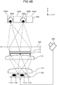
FIG. 4B is a view illustrating superposition of optical paths (the optical paths viewed from the X-axis direction) of light source elements. -
FIG. 4C is a view illustrating the optical paths when the optical paths are viewed from the X-axis direction in the first exemplary embodiment. -
FIG. 5A is a graph (a central portion in the X-axis direction) illustrating an outgoing light beam distribution of the display unit (liquid crystal panel) of the first exemplary embodiment. -
FIG. 5B is a graph (an end in the X-axis direction) illustrating the outgoing light beam distribution of the display unit (liquid crystal panel) of the first exemplary embodiment. -
FIG. 5C is a graph (a central portion in the Y-axis direction) illustrating the outgoing light beam distribution of the display unit (liquid crystal panel) of the first exemplary embodiment. -
FIG. 6A is a view illustrating the optical paths of the head-up display of the first exemplary embodiment. -
FIG. 6B is a view illustrating the optical paths of the head-up display of the first exemplary embodiment. -
FIG. 7A is a view illustrating lighting control in each region of an eye-box of a second exemplary embodiment. -
FIG. 7B is a view illustrating the lighting control in each region of the eye-box of the second exemplary embodiment. - Hereinafter, exemplary embodiments will be described in detail with reference to the drawings as appropriate. However, detailed description more than necessary may be omitted. For example, detailed description of a known matter or repetitive description of a substantially identical configuration may be omitted. Such omissions are aimed to prevent the following description from being redundant more than necessary, and to help those skilled in the art easily understand the following description. Note that the attached drawings and the following description are provided for those skilled in the art to fully understand the present disclosure, and are not intended to limit the subject matter as described in the appended claims.
- In the head-up display of PTL 1, the light beam emitted from the light source (light emitting diode) is condensed into the diffuser using the second condenser lens. Specifically, a plurality of lenses provided in the second condenser lens receive light beams from a plurality of light sources (light emitting diodes), respectively, and the light beams are output to the diffuser. That is, one lens receives the light beam from one light source. Therefore, luminance uniformity is generated near a boundary of a region irradiated with the light beams emitted from adjacent lenses in the condenser lens when the light beam emitted from each lens of the condenser lens is incident on the diffuser. Additionally, because of a configuration in which one light source illuminates a part of a display element, the light beams from all the light source elements reach a whole region of the eye-box irrespective of positions of driver's eyes. In other words, the light beams of the light sources are incident on a portion except for the positions of the driver's eyes on the eye-box, and a large amount of wasted light beam exists.
- Hereinafter, a first exemplary embodiment will be described with reference to the accompanying drawings.
-
FIG. 1 is a view illustrating a configuration of a head-up display mounted on a vehicle in the first exemplary embodiment. Head-updisplay 100 is mounted on vehicle 200 (an example of a moving body) includingwindshield 230. Head-updisplay 100 is constructed withdisplay unit 120, reflectionoptical unit 130,housing 140, andviewpoint detector 800.Display unit 120 includesillumination device 110,liquid crystal panel 115, andcontroller 700. - Head-up
display 100 projects an image ontowindshield 230 in order to causeobserver 300 to visually recognizevirtual image 400. -
Illumination device 110 illuminatesliquid crystal panel 115 that is of a display device.Liquid crystal panel 115 displays an image of a speedometer or a numerical value indicating speed, for example.Liquid crystal panel 115 acts as a spatial light modulation element that modulates light beams fromillumination device 110 using the displayed image. The modulated light beams are output fromliquid crystal panel 115 as transmitted light beams. The transmitted light beams are guided into eye-box 600 ofobserver 300 through reflectionoptical unit 130 andwindshield 230, and visually recognized asvirtual image 400 byobserver 300. For example,observer 300 can visually recognize the image such as the speedometer asvirtual image 400. As used herein, the eye-box means a region wherevirtual image 400 can visually be recognized byobserver 300 without any omission ofvirtual image 400. - Reflection optical unit 130 (an example of an optical element) includes
first mirror 131 andsecond mirror 132.First mirror 131 reflects the light beams outgoing fromliquid crystal panel 115 towardsecond mirror 132.Second mirror 132 reflects the light beams fromfirst mirror 131 towardwindshield 230.Second mirror 132 has a concave reflection surface. Reflectionoptical unit 130 is not always necessarily constructed with two mirrors, but may be constructed with one mirror or at least three mirrors. A refraction optical system such as a lens may further be disposed on an optical path of reflectionoptical unit 130. -
Housing 140 of head-updisplay 100 accommodatesdisplay unit 120 and reflectionoptical unit 130, andopening 141 through which the light beams from reflectionoptical unit 130 are output. A transparent cover may be provided inopening 141. -
Controller 700 is a processor that controlsillumination device 110 orliquid crystal panel 115.Controller 700 controls head-updisplay 100 based on information fromviewpoint detector 800. -
Viewpoint detector 800 is provided invehicle 200, and is a device that detects positions of right and left eyes ofobserver 300. For example,viewpoint detector 800 is an imaging device such as a camera or a sensor using an infrared light beam. -
FIG. 2 is a view illustrating a detailed configuration ofdisplay unit 120.Display unit 120 includesillumination device 110,liquid crystal panel 115, andcontroller 700.Liquid crystal panel 115 includesincident plane 115a on which the light beams are incident andoutgoing plane 115b from which the light beams are output.Incident plane 115a andoutgoing plane 115b have an identical shape, and a rectangular shape. - In the following description, a three-dimensional orthogonal coordinate system is set in each of the drawings. That is, an X-axis is set to a direction parallel to a longitudinal direction of
incident plane 115a andoutgoing plane 115b inliquid crystal panel 115, a Y-axis is set to a direction parallel to a crosswise direction ofincident plane 115a andoutgoing plane 115b, and a Z-axis is set to a direction parallel to a normal direction ofincident plane 115a andoutgoing plane 115b. - As illustrated in
FIG. 2 ,illumination device 110 is constructed with a plurality oflight source elements 111,first lens 112 disposed in an outgoing direction oflight source element 111,second lens 113 disposed in an outgoing direction offirst lens 112, and diffuser 114 (an example of a diffusion member) disposed in an outgoing direction ofsecond lens 113. - For example, each of
light source elements 111 is a chip type light emitting diode (LED), and is a luminous body that supplies an illumination light beam toliquid crystal panel 115. The plurality oflight source elements 111 are arranged in line in the longitudinal direction (the X-direction inFIG. 3 ). -
First lens 112 is disposed close tolight source elements 111 to an extent in which the outgoing light beam of eachlight source element 111 does not leak.First lens 112 takes in the outgoing light beam of eachlight source element 111 fromincident plane 112a.First lens 112 has a function of outputting the divergent light beams oflight source elements 111 while deflecting the divergent light beams into substantially parallel light beams in the Y-direction. Only onefirst lens 112 is disposed with respect to the plurality oflight source elements 111. - At least one of
incident plane 112a andoutgoing plane 112b offirst lens 112 has a convex shape such thatfirst lens 112 has positive refractive power. The convex shapes ofincident plane 112a andoutgoing plane 112b offirst lens 112 are not necessarily rotational symmetry with respect to an optical axis, but may be a toroidal shape in which the X-direction and the Y-direction differ from each other in a curvature. In the first exemplary embodiment,first lens 112 is a plano-convex lens in which onlyoutgoing plane 112b has a convex shape. -
Outgoing plane 112b offirst lens 112 is a convex plane having an aspherical shape in which the X-axis direction and the Y-axis direction differ from each other in a curvature. The X-axis direction ofoutgoing plane 112b has a shape in which the curvature is decreased from a center to an end (that is, a curvature radius is increased) such that an illuminance distribution becomes even ondiffuser 114 of the outgoing light beam of eachlight source element 111. The Y-axis direction ofoutgoing plane 112b has a shape in which the curvature at the end is smaller than that in the central portion such that the illuminance distribution becomes even ondiffuser 114. -
Second lens 113 has a function of deflecting the outgoing light beams offirst lens 112 in a desired direction. In the first exemplary embodiment,incident plane 113a ofsecond lens 113 has a shape in which onlyincident plane 113a in the X-axis direction is convex.Outgoing plane 113b ofsecond lens 113 has a convex shape in which the X-axis direction and the Y-axis direction differ from each other in a curvature.Incident plane 113a ofsecond lens 113 may have a convex shape in which the X-axis direction and the Y-axis direction differ from each other in a curvature.Outgoing plane 113b ofsecond lens 113 may have a shape in which one of the X-axis and the Y-axis direction is convex. The refractive power ofsecond lens 113 is set according to an outgoing angle of the outgoing light beams at the end of display unit 120 (or an incident angle of the light beams incident on diffuser 114).Second lens 113 is not always necessarily provided. A desired outgoing angle can be obtained at the end of thedisplay unit 120 only withfirst lens 112 with no use ofsecond lens 113 by lengthening a distance betweenfirst lens 112 anddiffuser 114. -
First lens 112 andsecond lens 113 are made of a transparent material having a predetermined refractive index. The refractive index of the transparent material ranges from 1.4 to 1.6, for example. Epoxy resin, silicone resin, acrylic resin, and resin such as polycarbonate can be used as the transparent material. In the first exemplary embodiment, the polycarbonate is used in consideration of a heat-resistant property. -
Diffuser 114 diffuses the light beams deflected byfirst lens 112 andsecond lens 113, and outputs the light beams toliquid crystal panel 115. Therefore, the luminance uniformity can be reduced in a video light beam, which is visually recognized in eye-box 600 and generated by the plurality oflight source elements 111.Diffuser 114 may be an optical member having a function of diffusing the light beams. For example, a surface ofdiffuser 114 is constructed with a bead material, a fine irregular structure, or a roughened surface. Furthermore, a dot sheet or a permeable, milky-white sheet may be used asdiffuser 114. -
Controller 700 controls lighting of the plurality oflight source elements 111 based on information aboutviewpoint detector 800 orliquid crystal panel 115. For example,controller 700 is constructed with a microcomputer. - Optical paths of the light beams emitted from
light source elements 111 of head-updisplay 100 of the first exemplary embodiment will be described below. - Each of
FIGS. 3A and3B is a view illustrating the optical paths fromliquid crystal panel 115 in head-updisplay 100 to eye-box 600.Observer 300 visually recognizes the transmitted light beams ofliquid crystal panel 115 through virtual imageoptical system 500. Virtual imageoptical system 500 is a combination of reflectionoptical unit 130 andwindshield 230 inFIG. 1 .FIG. 3A illustrates the optical paths when the optical path is viewed from a long-side side ofliquid crystal panel 115, andFIG. 3B illustrates the optical paths when the optical path is viewed from a short-side side ofliquid crystal panel 115. - In the case that
liquid crystal panel 115 is disposed such thatincident plane 115a ofliquid crystal panel 115 becomes parallel to the outgoing plane ofillumination device 110, the outgoing angles of the outgoing light beams fromliquid crystal panel 115 toward the central portion of eye-box 600 vary in the central portion and the end ofliquid crystal panel 115. Specifically, outgoing angle α1 in the central portion ofliquid crystal panel 115 is larger than outgoing angle α2 at the end ofliquid crystal panel 115. That is, the outgoing light beam in the central portion ofliquid crystal panel 115 is output in the normal direction ofoutgoing plane 115b ofliquid crystal panel 115, and the outgoing light beam at the end is output toward the outside ofoutgoing plane 115b ofliquid crystal panel 115. Unlessliquid crystal panel 115 is disposed in parallel toillumination device 110, the outgoing light beam in the central portion has an inclination with respect to the normal direction ofoutgoing plane 115b ofliquid crystal panel 115. In eye-box 600, because a length in the X-direction is generally longer than a length in the Y-direction, light distribution angle 61 (seeFIG. 3A ) in the X-axis direction is larger than light distribution angle 62 (seeFIG. 3B ) in the Y-axis direction. -
FIG. 4A is a view illustrating the optical paths fromlight source elements 111 to eye-box 600 when the optical paths are viewed from the Y-axis direction.First lens 112 deflects the outgoing light beam from eachlight source element 111 such that outgoing light beams from the plurality oflight source elements 111 are superposed at the position ofdiffuser 114. - That is, the refractive power of
first lens 112 is set such that each of the plurality oflight source elements 111 illuminates the whole surface ofliquid crystal panel 115 whenfirst lens 112 is viewed from the Y-axis direction. For example, as illustrated inFIG. 4B , both the outgoing light beam fromlight source element 111a and the outgoing light beam fromlight source element 111c illuminate the whole region ofliquid crystal panel 115. The same holds true forlight source elements - Thus, the light beams from the plurality of
light source elements 111 illuminate the whole (identical region) ofliquid crystal panel 115 while being superposed on each other. Therefore,virtual image 400 visually recognized in eye-box 600 has even luminance. - A focal length of
first lens 112 is set such that outgoing light beams fromlight source elements 111a to 111d illuminate the identical region ofliquid crystal panel 115 while being superposed on each other. Specifically,first lens 112 is designed such that the focal length offirst lens 112 becomes identical to a distance from an optical center offirst lens 112 toliquid crystal panel 115. - The focal length of
first lens 112 may be set to a value larger than the distance from the optical center offirst lens 112 toliquid crystal panel 115 as long as the substantially identical region ofliquid crystal panel 115 is illuminated with the outgoing light beams emitted from the plurality oflight source elements 111 while the outgoing light beams are superposed on each other. -
Second lens 113 is used in order to adjust the incident angles fromfirst lens 112 toliquid crystal panel 115 of the outgoing light beams. That is,second lens 113 deflects each outgoing light beam fromfirst lens 112 in a direction inclined to a predetermined angle. The predetermined angle is an angle at which the outgoing angles are obtained in the central portion and the end ofliquid crystal panel 115 as illustrated inFIGS. 3A and3B . That is, the refractive power ofsecond lens 113 is set such that the outgoing angles are obtained according to virtual imageoptical system 500. As described above,second lens 113 is not always necessarily provided. -
Diffuser 114 weakens directivity of the light beams incident ondiffuser 114. In the case that diffuser 114 is not provided, the light beam outgoing fromliquid crystal panel 115 has a light distribution characteristic having a peak of the light intensity in the direction corresponding to each of the plurality oflight sources 111.Diffuser 114, when provided, diffuses the light beams incident onliquid crystal panel 115, the light beams are transmitted throughliquid crystal panel 115, and the light distribution characteristics of the outgoing light beams is smoothed. The light beam emitted from each of the plurality oflight source elements 111 is incident ondiffuser 114 at a different angle corresponding to a disposition position of each oflight source elements 111. Because the light distribution angle in the X-axis direction ofdiffuser 114 is a light distribution angle of the outgoing light beam for a combination of the incident light beams from the plurality oflight sources 111 arrayed in the X-axis direction, the light distribution angle in the X-axis direction ofdiffuser 114 becomes larger than a diffusion characteristic ofdiffuser 114 itself. Therefore, in the X-axis direction, compared with the Y-axis direction, the light distribution angle can be increased larger than the diffusion characteristic ofdiffuser 114. The light distribution angle of the outgoing light beam ofliquid crystal panel 115 can be controlled by changing the dispositions of the plurality oflight source elements 111. A difference in angle incident ondiffuser 114 increases by widening a gap betweenlight source elements 111, and an appearance gap between the peaks of light intensity is widened. Accordingly, in the case that an identical number oflight source elements 111 is used, the light distribution angle ofliquid crystal panel 115 can be increased by widening the gap betweenlight source elements 111 However, it is necessary to widen the gap betweenlight source elements 111 to an extent in which the outgoing light beams oflight source elements 111 necessarily enterfirst lens 112 without being leaked. -
FIG. 4C is a view illustrating the optical paths fromlight source element 111 to eye-box 600 when the optical paths are viewed from the X-axis direction. The outgoing light beams oflight source element 111 are incident onfirst lens 112, and are deflected to an extent in which the outgoing light beams become outward light beams throughsecond lens 113. In the first exemplary embodiment,virtual image 400 includes a long side (a side extending in the longitudinal direction of liquid crystal panel 115) and a short side (a side extending in the crosswise direction of liquid crystal panel 115). In the Y-axis direction indicating a short-side direction ofillumination device 110, the refractive powers offirst lens 112 andsecond lens 113 are set such that a light distribution angle of the outgoing light beam ofliquid crystal panel 115 is narrowed compared with the X-axis direction. -
Diffuser 114 has a function of diffusing and outputting the light beams incident ondiffuser 114 according to a predetermined light distribution characteristic (diffusion angle). The light distribution characteristic is set such that the light beams, which are output fromdiffuser 114 and passed through virtual imageoptical system 500, finally have a spread corresponding to a width of eye-box 600. In the case that light distribution characteristic is set indiffuser 114 so as to obtain the spread corresponding to the width in the Y-axis direction of eye-box 600, sometimes the smoothing of the angle characteristic in the X-axis direction is not completely accomplished. In this case, an anisotropic material having different diffusion properties (diffusion angles) in the X-axis direction and the Y-axis direction may be used as a material fordiffuser 114. The plurality oflight source elements 111 may be disposed by adjusting the gap betweenlight source elements 111. -
FIG. 5A is a graph illustrating a light distribution characteristic of the outgoing light beam in a central portion of the X-axis direction that is of the longitudinal direction ofliquid crystal panel 115 of the first exemplary embodiment.FIG. 5B is a graph illustrating the light distribution characteristic of the outgoing light beam at an end of the X-axis direction that is of the longitudinal direction ofliquid crystal panel 115 of the first exemplary embodiment.FIG. 5C is a graph illustrating the light distribution characteristic of the outgoing light beam in the central portion of the Y-axis direction that is of the crosswise direction ofliquid crystal panel 115 of the first exemplary embodiment. In the graphs ofFIGS. 5A to 5C , a vertical axis indicates light intensity ofliquid crystal panel 115 with a unit of candela, and a horizontal axis indicates the light distribution angle of the light beam ofliquid crystal panel 115 with a unit of degree. - With reference to
FIGS. 5A and 5B , in the central portion ofliquid crystal panel 115, the outgoing light beam has a peak intensity of the outgoing light beam in the normal direction ofoutgoing plane 115b ofliquid crystal panel 115. On the other hand, as can be seen fromFIGS. 5A and 5B , at the end ofliquid crystal panel 115, the outgoing light beam has a peak intensity in a direction inclined toward the outside ofliquid crystal panel 115 based on the normal direction. As illustrated inFIGS. 5A and 5C , inliquid crystal panel 115 of the first exemplary embodiment, the light distribution angle in the X-axis direction is larger than the light distribution angle in the Y-axis direction. Therefore, the virtual image having an even luminance distribution in eye-box 600 can visually be recognized in head-updisplay 100 in whichvirtual image 400 larger than an area ofliquid crystal panel 115 is displayed. - Each of
FIGS. 6A and6B is a view schematically illustrating a method for controllinglight source elements 111 of head-updisplay 100 of the first exemplary embodiment. In the first exemplary embodiment,controller 700 controls a lighting state of each oflight source elements 111 according to information about the viewpoint position ofobserver 300, the viewpoint position being obtained byviewpoint detector 800. - The outgoing light beams emitted from
light source elements 111a to 111d are respectively incident on positions corresponding to eye-boxpartial regions 600a to 600d into which eye-box 600 is divided. That is, the light beam oflight source element 111a located at the end oflight source elements 111 is mainly incident on eye-boxpartial region 600a located at the end of eye-box 600. The light beam oflight source element 111d located at an opposite end to thelight source element 111a oflight source elements 111 is mainly incident on eye-boxpartial region 600d located on an opposite end to eye-boxpartial region 600a of eye-box 600. The position on which the outgoing light beam of each oflight source elements 111a to 111d is incident depends on the disposition position of each oflight source elements 111a to 111d, and a number of partial regions of eye-box 600 can be identical to a number oflight source elements 111. -
Viewpoint detector 800 detects which region of eye-boxpartial regions 600a to 600d the right and left eyes ofobserver 300 are located.Controller 700 controls light intensity of each oflight source elements 111a to 111d according to an eye position ofobserver 300, the eye position being detected byviewpoint detector 800. For this reason,controller 700 previously includes a table in whichlight source element 111 to be lit is decided according to the eye position ofobserver 300, the eye position being detected byviewpoint detector 800.. In the first exemplary embodiment, as illustrated inFIG. 6A , in the case that lefteye 300a ofobserver 300 is located in the center of eye-boxpartial region 600a whileright eye 300b ofobserver 300 is located in the center of eye-boxpartial region 600c,light source element 111a forleft eye 300a is lit,light source element 111c forright eye 300b is lit, andlight source elements - The case that the eye positions of
observer 300 move from the state inFIG. 6A to the left direction (a negative direction of an X-coordinate) in a paper plane ofFIG. 6A will be described. For example, in the case that lefteye 300a ofobserver 300 is located at a boundary between eye-boxpartial regions right eye 300b ofobserver 300 is located at a boundary between eye-boxpartial regions light source elements left eye 300a andlight source elements right eye 300b are lit with light intensity lower than that of the case that the eye positions ofobserver 300 are located in the center of the corresponding eye-box partial region. - The case that the eye positions of
observer 300 further move from the above state to the left direction (the negative direction of an X-coordinate) in the paper plane will be described.FIG. 6B illustrates the case that the eye positions ofobserver 300 move such that lefteye 300a of the observer is located in the center of eye-boxpartial region 600b and such thatright eye 300b of the observer is located in the center of eye-boxpartial region 600d. At this point,light source element 111b forleft eye 300a andlight source element 111d forright eye 300b are lit, andlight source elements - In the first exemplary embodiment, the illumination regions of eye-
box 600 are changed by controlling the lighting states oflight source elements 111. This is becausefirst lens 112 andsecond lens 113 are configured such that the position in eye-box 600 on which the light beam is incident from each of the plurality oflight source elements 111a to 111d differs from each other while each oflight source elements 111a to 111d illuminates the whole region ofliquid crystal panel 115. - As described above, in the first exemplary embodiment, head-up
display 100 projects the image onto eye-box 600 ofobserver 300. Head-updisplay 100 includes the plurality oflight source elements 111, liquid crystal panel 115 (an example of the transmission type display element), first lens 112 (an example of the optical member),viewpoint detector 800, andcontroller 700. The plurality oflight source elements 111 are arranged into an array shape, and output the light beams.Liquid crystal panel 115 displays the image.First lens 112 deflects the light beams emitted from the plurality oflight source elements 111 such that the light beams illuminate the identical region inincident plane 115a ofliquid crystal panel 115.Viewpoint detector 800 detects the eye position (an example of the viewpoint position) ofobserver 300.Controller 700 controls the plurality oflight source elements 111 according to the eye position ofobserver 300, the eye position being detected byviewpoint detector 800. - Therefore, only eye-box
partial regions illumination device 110, andobserver 300 can visually recognizevirtual image 400. On the other hand, eye-boxpartial regions - Even if the eye is located at a boundary between the eye-box partial regions,
observer 300 can visually recognizevirtual image 400 without changing the luminance. - Head-up
display 100 according to a second exemplary embodiment differs from head-updisplay 100 of the first exemplary embodiment in thatlight source element 111 is constructed with ninelight source elements 111a to 111i, and head-updisplay 100 of the second exemplary embodiment is similar to head-updisplay 100 of the first exemplary embodiment in other configurations. Therefore, the description is omitted. - Each of
FIGS. 7A and 7B is a view illustrating a light intensity distribution in each of eye-boxpartial regions 600a to 600i. The intensity of the incident light beam from each oflight source elements 111a to 111i is maximized in the corresponding region of eye-boxpartial regions 600a to 600i of eye-box 600. Becauselight source elements 111a to 111i of head-updisplay 100 of the second exemplary embodiment are densely disposed, each of the outgoing light beams oflight source elements 111a to 111i is incident on not only the corresponding eye-box partial region but also the adjacent eye-box partial regions. -
FIG. 7A is a view illustrating the light intensity distribution in eye-box 600 when lefteye 300a ofobserver 300 is located in eye-boxpartial region 600c whileright eye 300b ofobserver 300 is located in eye-boxpartial region 600g. At this point,light source elements left eye 300a. Light source elements 111f, 111g, 111h are lit forright eye 300b. At this point,light source elements 111a, 111e, 111i are turned off because the outgoing light beams oflight source elements 111a, 111e, 111i are not incident on the viewpoint position ofobserver 300. -
FIG. 7B is a view illustrating the light intensity distribution in eye-box 600 whenobserver 300 moves from the state inFIG. 7A to the left side in the paper plane. Specifically, the case that lefteye 300a ofobserver 300 moves from eye-boxpartial region 600c to eye-boxpartial region 600d whileright eye 300b ofobserver 300 moves from eye-boxpartial region 600g to eye-boxpartial region 600h will be described. In this case, whenleft eye 300a ofobserver 300 enters eye-boxpartial region 600d, light source element 111e forleft eye 300a is lit in addition tolight source elements Light source element 111b can be turned off because the outgoing light beam oflight source element 111b is not incident onleft eye 300a. Similarly, light source element 111i forright eye 300b is lit in addition to light source elements 111g, 111h. Light source element 111f is turned off because the outgoing light beam of light source element 111f is not incident onright eye 300b. That is,light source elements virtual image 400 visually recognized byobserver 300, because the number of light source elements that illuminate the viewpoint position ofobserver 300 does not change when the light source element to be turned off and the light source element to be lit are simultaneously controlled. - According to the configuration of the second exemplary embodiment,
illumination device 110 selectively illuminates only the eye-box partial regions where the eyes ofobserver 300 are located, and thusobserver 300 can visually recognizevirtual image 400. On the other hand,light source elements 111 to illuminate the eye-box partial regions where the eyes ofobserver 300 are not located are turned off, so that the power saving is achieved. - In
FIGS. 7A and 7B , light intensity distribution is indicated by a solid line in each litlight source element 111. The intensity distribution of the light beam incident on eye-box 600 is indicated by a hatched portion. That is, the hatched portion is a combination of the light intensity distributions indicated by the solid lines. As can be seen from the eye positions ofobserver 300 and the intensity distributions of the hatched portions inFIGS. 7A and 7B , a large change in light intensity around the eyes ofobserver 300 is suppressed. Therefore, in the case that the control oflight source elements 111 incompletely follows the movement of the eyes ofobserver 300, the change in luminance ofvirtual image 400 can be suppressed when thevirtual image 400 is viewed fromobserver 300. - The first and second exemplary embodiments are described above as illustration of the technique disclosed in this application. However, the technique of the present disclosure is not limited to the first and second exemplary embodiments, but is applicable to exemplary embodiments where modifications, replacements, additions, omissions, and the like are appropriately made. Additionally, components described in the first and second exemplary embodiments can be combined to make a new exemplary embodiment. Then, other exemplary embodiments will be described below.
- In the first and second exemplary embodiments,
liquid crystal panel 115 is used as the spatial light modulation element. However, another display element can be used as long as the display element is a transmission type display device. - By way of example,
liquid crystal panel 115 is disposed so as to be orthogonal to the main light beam oflight source element 111. Alternatively,liquid crystal panel 115 may be disposed so as not to be orthogonal to the main light beam oflight source element 111, but be inclined relative to the main light beam. - A Fresnel lens can be used in the outgoing planes and the incident planes of
first lens 112 andsecond lens 113. Therefore, a thinner lens can be provided. - The focal length of
first lens 112 may be set to a value equal to or larger than the distance from the optical center offirst lens 112 tooutgoing plane 113b ofsecond lens 113 as long as the substantially identical region ofliquid crystal panel 115 is illuminated with the outgoing light beams emitted from the plurality oflight source elements 111 while the outgoing light beams are superposed on each other. Therefore, the virtual image in which the luminance uniformity is reduced can be generated. - In the first and second exemplary embodiments, one
first lens 112 is disposed with respect to the plurality oflight source elements 111. Alternatively, a plurality of first lenses may be disposed with respect to the plurality oflight source elements 111. - Although the convex lens is used as
first lens 112, a total internal reflection (TIR) lens can also be used. Therefore, the light beams can efficiently be emitted fromlight source elements 111 tosecond lens 113, and therefore light use efficiency is improved. - In
illumination device 110 of the first and second exemplary embodiments,light source elements 111 are disposed in only one line in the Y-axis direction (the crosswise direction of liquid crystal panel 115). Alternatively, in the Y-axis direction,light source elements 111 may be disposed in a plurality of lines. - In the first and second exemplary embodiments,
diffuser 114 is disposed betweensecond lens 113 andliquid crystal panel 115. Alternatively,diffuser 114 may be disposed betweenfirst lens 112 andsecond lens 113. Although the efficiency is degraded, the luminance uniformity can be reduced even in this position. - By way of example,
windshield 230 is used as the member reflecting the outgoing light beams of head-updisplay 100. Alternatively, a combiner may be used. - By way of example, the LED is used as the light source. Alternatively, a laser diode or an organic light emitting diode may be used.
- In the first and second exemplary embodiments, the head-up display in which the image is observed by using both the eyes is described as the light source control method. However, a head-up display in which the image is observed by using a simple eye can be constructed by performing the similar control. In a conventional simple-eye head-up display device, both the eyes are irradiated with the light beams depending on the eye positions of the observer, and sometimes the virtual image is visually recognized with both the eyes. When the control is performed like the first and second exemplary embodiments, only the simple eye is easy to be illuminated.
-
Viewpoint detector 800 may detect the eye position by not only directly detecting the eye position but also estimating the eye position from eyebrows, a nose, or an outline of a face. - In the first and second exemplary embodiments, the power saving is achieved by the control of the turn-off and the lighting according to the eye position of the observer. Alternatively,
light source elements 111 may be moved according to the eye position ofobserver 300 for the power saving. - In the second exemplary embodiment, by way of example, the light source elements whose light beams do not reach the eye of
observer 300 are turned off. Alternatively,light source elements 111 may be lit while the light intensity oflight source elements 111 is lowered. Therefore, the luminance uniformity can be reduced in the case that the eyes of the observer each are located at the boundary portions between the eye-box partial regions. - The display image of
liquid crystal panel 115 is time-divided to present different images to the right and left eyes, which allows the observer to recognize a stereoscopic image. In this case, the turn-off and the lighting of the light source elements are controlled such that only the eye-box partial region where the right eye is located is illuminated when the right eye image is displayed. On the other hand, the turn-off and the lighting of the light source elements are controlled such that only the eye-box partial region where the left eye is located is illuminated when the left eye image is displayed, which allows naked eye stereoscopic display. - The moving body on which head-up
display 100 of the first and second exemplary embodiments is mounted is not limited to an automobile, but includes a railroad vehicle, a motorcycle, an airplane, a helicopter, a vessel, and various devices that carry people. - The present disclosure is applicable to a projection device that causes an observer to visually recognize a virtual image. Specifically, the present disclosure is applicable to a head-up display and the like.
-
- 100
- head-up display
- 110
- illumination device
- 111
- light source element
- 112
- first lens
- 112a
- incident plane (of first lens)
- 112b
- outgoing plane (of first lens)
- 113
- second lens
- 113a
- incident plane (of second lens)
- 113b
- outgoing plane (of second lens)
- 114
- diffuser (diffusion member)
- 115
- liquid crystal panel
- 115a
- incident plane (of liquid crystal panel)
- 115b
- outgoing plane (of liquid crystal panel)
- 120
- display unit
- 130
- reflection optical unit
- 131
- first mirror
- 132
- second mirror
- 140
- housing
- 141
- opening
- 200
- vehicle
- 230
- windshield
- 300
- observer
- 300a
- left eye
- 300b
- right eye
- 400
- virtual image
- 500
- virtual image optical system
- 600
- eye-box
- 700
- controller
Claims (8)
- A head-up display that projects an image onto an eye-box of an observer, the head-up display comprising:a plurality of light source elements that are arranged in an array and that emit light beams;a transmission type display element that displays the image;an optical member that deflects the light beams emitted from the plurality of light source elements such that an identical region in an incident plane of the transmission type display element is illuminated with the light beams;a viewpoint detector that detects a viewpoint position of the observer; anda controller that controls intensity of the light beam of each of the plurality of light source elements according to the viewpoint position detected by the viewpoint detector.
- The head-up display according to claim 1, wherein a focal length of the optical member is set equal or larger than a value of a distance from an optical center of the optical member to the transmission type display element.
- The head-up display according to claim 1, wherein the optical member is configured by a lens element.
- The head-up display according to claim 1, wherein the optical member includes a first lens element and a second lens element disposed on an outgoing plane side of the first lens element.
- The head-up display according to claim 1, wherein
at least parts of outgoing light beams of the plurality of light source elements are incident on different regions of the eye-box, and
the controller turns off each of the plurality of light source elements, the light beam being projected onto a region where the viewpoint position of the observer in the eye-box does not exist, in the plurality of light source elements. - The head-up display according to claim 1, wherein, when the viewpoint position of the observer is located at a boundary of a plurality of regions in the eye-box, the controller lowers an intensity of an outgoing light beam of each of plurality of the light source elements compared with when the viewpoint position of the observer is not located at the boundary of the plurality of regions in the eye-box.
- The head-up display according to claim 1, wherein the head-up display is mounted on a moving body including a windshield.
- A moving body on which the head-up display according to claim 1 is mounted.
Applications Claiming Priority (2)
| Application Number | Priority Date | Filing Date | Title |
|---|---|---|---|
| JP2015132282 | 2015-07-01 | ||
| PCT/JP2016/003053 WO2017002344A1 (en) | 2015-07-01 | 2016-06-24 | Head-up display and moving body comprising head-up display |
Publications (3)
| Publication Number | Publication Date |
|---|---|
| EP3287834A1 true EP3287834A1 (en) | 2018-02-28 |
| EP3287834A4 EP3287834A4 (en) | 2018-03-14 |
| EP3287834B1 EP3287834B1 (en) | 2019-08-07 |
Family
ID=57608187
Family Applications (1)
| Application Number | Title | Priority Date | Filing Date |
|---|---|---|---|
| EP16817455.5A Active EP3287834B1 (en) | 2015-07-01 | 2016-06-24 | Head-up display and moving body comprising head-up display |
Country Status (4)
| Country | Link |
|---|---|
| US (1) | US10302943B2 (en) |
| EP (1) | EP3287834B1 (en) |
| JP (1) | JP6586646B2 (en) |
| WO (1) | WO2017002344A1 (en) |
Cited By (5)
| Publication number | Priority date | Publication date | Assignee | Title |
|---|---|---|---|---|
| CN109849791A (en) * | 2019-03-07 | 2019-06-07 | 宁波吉利汽车研究开发有限公司 | A kind of assisted driving system and vehicle |
| EP3543771A1 (en) * | 2018-03-20 | 2019-09-25 | Panasonic Intellectual Property Management Co., Ltd. | Head-up display and moving object |
| FR3083331A1 (en) * | 2018-06-29 | 2020-01-03 | Faurecia Interieur Industrie | AUGMENTED REALITY DEVICE FOR VEHICLE |
| CN114994940A (en) * | 2022-02-16 | 2022-09-02 | 友达光电股份有限公司 | Naked eye type stereo display system and display method thereof |
| WO2023104257A1 (en) * | 2021-12-06 | 2023-06-15 | Continental Automotive Technologies GmbH | Method, computer program and device for controlling an imaging unit of a display device, and display device |
Families Citing this family (24)
| Publication number | Priority date | Publication date | Assignee | Title |
|---|---|---|---|---|
| US11126005B2 (en) * | 2016-10-24 | 2021-09-21 | Maxell, Ltd. | Head up display system for expanding a display range of a virtual image |
| US10762810B2 (en) * | 2018-01-05 | 2020-09-01 | North Inc. | Augmented reality eyebox fitting optimization for individuals |
| US10884249B2 (en) * | 2018-10-23 | 2021-01-05 | Panasonic Automotive Systems Company Of America, Division Of Panasonic Corporation Of North America | Combiner head up display with separate infrared function |
| JP2020109453A (en) | 2019-01-07 | 2020-07-16 | 矢崎総業株式会社 | Head-up display device |
| JP7131397B2 (en) * | 2019-01-10 | 2022-09-06 | 株式会社デンソー | virtual image display |
| CN111948812B (en) | 2019-05-17 | 2026-01-27 | 未来(北京)黑科技有限公司 | Head-up display system |
| JP7509150B2 (en) * | 2019-09-24 | 2024-07-02 | 日本精機株式会社 | Head-up display |
| CN112622767A (en) | 2019-10-08 | 2021-04-09 | 松下知识产权经营株式会社 | Display system and electronic rearview mirror system provided with same |
| JP7276062B2 (en) * | 2019-10-09 | 2023-05-18 | 株式会社デンソー | Virtual image display device and display control device |
| JP2021084466A (en) * | 2019-11-26 | 2021-06-03 | 矢崎総業株式会社 | Vehicle display device |
| JP7584001B2 (en) * | 2020-03-25 | 2024-11-15 | 日本精機株式会社 | Head-up display device, display control device, and display control method |
| JP2022026716A (en) * | 2020-07-31 | 2022-02-10 | 日本精機株式会社 | Head-up display device |
| JP2022026522A (en) * | 2020-07-31 | 2022-02-10 | 日本精機株式会社 | Head-up display device |
| JP7494646B2 (en) * | 2020-08-24 | 2024-06-04 | 日本精機株式会社 | Head-up display device, display control device, and control method for head-up display device |
| JP7569497B2 (en) * | 2020-08-31 | 2024-10-18 | 日本精機株式会社 | Display control device, head-up display device |
| US11960080B2 (en) * | 2020-10-20 | 2024-04-16 | Nippon Seiki Co., Ltd. | Head-up display device |
| JP7579504B2 (en) * | 2020-11-27 | 2024-11-08 | 日本精機株式会社 | Display control device, head-up display device, and display control method |
| JP7661769B2 (en) * | 2021-04-30 | 2025-04-15 | 日本精機株式会社 | Display control device, head-up display device, and display control method |
| JP7661790B2 (en) * | 2021-05-27 | 2025-04-15 | 日本精機株式会社 | Head-up display device |
| FR3125895B1 (en) * | 2021-07-30 | 2026-04-17 | Valeo Comfort & Driving Assistance | Image generation device and head-up display incorporating such a device |
| KR102730251B1 (en) * | 2022-02-16 | 2024-11-13 | 현대모비스 주식회사 | Head-Up Display Apparatus And Control Method Therefor |
| KR20230123200A (en) * | 2022-02-16 | 2023-08-23 | 현대모비스 주식회사 | Head-Up Display Apparatus And Control Method Therefor |
| US12159560B2 (en) | 2023-03-22 | 2024-12-03 | Ford Global Technologies, Llc | Projector power management for head-up displays |
| US12472815B2 (en) * | 2023-07-12 | 2025-11-18 | Infineon Technologies Austria Ag | Driver and passenger aware content projection |
Family Cites Families (14)
| Publication number | Priority date | Publication date | Assignee | Title |
|---|---|---|---|---|
| JP3556306B2 (en) * | 1995-02-06 | 2004-08-18 | オリンパス株式会社 | Video display device |
| US5714967A (en) * | 1994-05-16 | 1998-02-03 | Olympus Optical Co., Ltd. | Head-mounted or face-mounted image display apparatus with an increased exit pupil |
| JP3717654B2 (en) | 1998-02-17 | 2005-11-16 | 株式会社リコー | Color image display device |
| JP4490605B2 (en) * | 2001-07-26 | 2010-06-30 | 矢崎総業株式会社 | In-vehicle head-up display device |
| JP4686462B2 (en) | 2003-09-30 | 2011-05-25 | コーニンクレッカ フィリップス エレクトロニクス エヌ ヴィ | Light source array for liquid crystal display applications |
| JP2007108429A (en) | 2005-10-13 | 2007-04-26 | Denso Corp | Display device and vehicle head-up display device including the same |
| US7542210B2 (en) * | 2006-06-29 | 2009-06-02 | Chirieleison Sr Anthony | Eye tracking head mounted display |
| JP2010197493A (en) * | 2009-02-23 | 2010-09-09 | Nippon Sheet Glass Co Ltd | Head-up display |
| JP2011059270A (en) * | 2009-09-08 | 2011-03-24 | Nippon Seiki Co Ltd | Display device for vehicle |
| KR101408501B1 (en) | 2010-01-12 | 2014-06-17 | 가부시키가이샤 니콘 | Display device and display method |
| JP5463939B2 (en) | 2010-02-01 | 2014-04-09 | 株式会社ニコン | Display device and display method |
| US9097890B2 (en) * | 2010-02-28 | 2015-08-04 | Microsoft Technology Licensing, Llc | Grating in a light transmissive illumination system for see-through near-eye display glasses |
| JP6279881B2 (en) * | 2013-11-01 | 2018-02-14 | Necプラットフォームズ株式会社 | Virtual image display device |
| JP6098486B2 (en) * | 2013-11-18 | 2017-03-22 | 三菱電機株式会社 | Vehicle display device |
-
2016
- 2016-06-24 WO PCT/JP2016/003053 patent/WO2017002344A1/en not_active Ceased
- 2016-06-24 JP JP2017526172A patent/JP6586646B2/en active Active
- 2016-06-24 EP EP16817455.5A patent/EP3287834B1/en active Active
-
2017
- 2017-12-12 US US15/839,489 patent/US10302943B2/en active Active
Cited By (8)
| Publication number | Priority date | Publication date | Assignee | Title |
|---|---|---|---|---|
| EP3543771A1 (en) * | 2018-03-20 | 2019-09-25 | Panasonic Intellectual Property Management Co., Ltd. | Head-up display and moving object |
| FR3083331A1 (en) * | 2018-06-29 | 2020-01-03 | Faurecia Interieur Industrie | AUGMENTED REALITY DEVICE FOR VEHICLE |
| CN109849791A (en) * | 2019-03-07 | 2019-06-07 | 宁波吉利汽车研究开发有限公司 | A kind of assisted driving system and vehicle |
| WO2023104257A1 (en) * | 2021-12-06 | 2023-06-15 | Continental Automotive Technologies GmbH | Method, computer program and device for controlling an imaging unit of a display device, and display device |
| CN114994940A (en) * | 2022-02-16 | 2022-09-02 | 友达光电股份有限公司 | Naked eye type stereo display system and display method thereof |
| US20230262206A1 (en) * | 2022-02-16 | 2023-08-17 | Au Optronics Corporation | Naked-eye stereoscopic display system and display method thereof |
| US11825067B2 (en) * | 2022-02-16 | 2023-11-21 | Au Optronics Corporation | Naked-eye stereoscopic display system and display method thereof |
| CN114994940B (en) * | 2022-02-16 | 2024-04-12 | 友达光电股份有限公司 | Naked eye stereoscopic display system and display method thereof |
Also Published As
| Publication number | Publication date |
|---|---|
| JPWO2017002344A1 (en) | 2018-05-24 |
| US10302943B2 (en) | 2019-05-28 |
| WO2017002344A1 (en) | 2017-01-05 |
| EP3287834B1 (en) | 2019-08-07 |
| JP6586646B2 (en) | 2019-10-09 |
| EP3287834A4 (en) | 2018-03-14 |
| US20180101007A1 (en) | 2018-04-12 |
Similar Documents
| Publication | Publication Date | Title |
|---|---|---|
| US10302943B2 (en) | Head-up display and moving body comprising head-up display | |
| JP5866644B1 (en) | Head-up display and moving body with head-up display | |
| JP6823817B2 (en) | Head-up display device | |
| JP6078798B2 (en) | Head-up display, lighting device, and moving body equipped with the same | |
| KR101274891B1 (en) | Head-up display device for projecting image on screen | |
| JP6098375B2 (en) | Head-up display device | |
| EP3543771A1 (en) | Head-up display and moving object | |
| CN109946838B (en) | Head-up display device | |
| US20180259773A1 (en) | Image display device and headup display equipped with image display device | |
| CN109313348B (en) | Optical Devices and Optical Systems | |
| EP4481270A1 (en) | Optical member, light source device, and head-up display | |
| KR102362729B1 (en) | Head up display apparatus | |
| US11415800B2 (en) | Head-up display | |
| CN118511109A (en) | Light source device and head-up display |
Legal Events
| Date | Code | Title | Description |
|---|---|---|---|
| STAA | Information on the status of an ep patent application or granted ep patent |
Free format text: STATUS: THE INTERNATIONAL PUBLICATION HAS BEEN MADE |
|
| PUAI | Public reference made under article 153(3) epc to a published international application that has entered the european phase |
Free format text: ORIGINAL CODE: 0009012 |
|
| STAA | Information on the status of an ep patent application or granted ep patent |
Free format text: STATUS: REQUEST FOR EXAMINATION WAS MADE |
|
| 17P | Request for examination filed |
Effective date: 20171124 |
|
| AK | Designated contracting states |
Kind code of ref document: A1 Designated state(s): AL AT BE BG CH CY CZ DE DK EE ES FI FR GB GR HR HU IE IS IT LI LT LU LV MC MK MT NL NO PL PT RO RS SE SI SK SM TR |
|
| AX | Request for extension of the european patent |
Extension state: BA ME |
|
| A4 | Supplementary search report drawn up and despatched |
Effective date: 20180212 |
|
| RIC1 | Information provided on ipc code assigned before grant |
Ipc: G02B 27/01 20060101AFI20180206BHEP Ipc: G02B 27/00 20060101ALI20180206BHEP Ipc: G02B 26/02 20060101ALI20180206BHEP Ipc: G06F 3/01 20060101ALI20180206BHEP Ipc: B60Q 3/18 20170101ALI20180206BHEP Ipc: B60K 35/00 20060101ALI20180206BHEP Ipc: G09F 9/00 20060101ALI20180206BHEP Ipc: G02B 26/00 20060101ALI20180206BHEP Ipc: G09G 5/00 20060101ALI20180206BHEP Ipc: B60R 21/015 20060101ALI20180206BHEP Ipc: G09G 3/20 20060101ALI20180206BHEP |
|
| DAV | Request for validation of the european patent (deleted) | ||
| DAX | Request for extension of the european patent (deleted) | ||
| GRAP | Despatch of communication of intention to grant a patent |
Free format text: ORIGINAL CODE: EPIDOSNIGR1 |
|
| STAA | Information on the status of an ep patent application or granted ep patent |
Free format text: STATUS: GRANT OF PATENT IS INTENDED |
|
| RIC1 | Information provided on ipc code assigned before grant |
Ipc: G02B 26/02 20060101ALI20190123BHEP Ipc: G09F 9/00 20060101ALI20190123BHEP Ipc: G02B 27/01 20060101AFI20190123BHEP Ipc: G09G 3/20 20060101ALI20190123BHEP Ipc: B60K 35/00 20060101ALI20190123BHEP Ipc: G02B 27/00 20060101ALI20190123BHEP Ipc: G02B 26/00 20060101ALI20190123BHEP Ipc: G09G 5/00 20060101ALI20190123BHEP Ipc: B60R 21/015 20060101ALI20190123BHEP Ipc: B60Q 3/18 20170101ALI20190123BHEP Ipc: G06F 3/01 20060101ALI20190123BHEP |
|
| INTG | Intention to grant announced |
Effective date: 20190220 |
|
| GRAS | Grant fee paid |
Free format text: ORIGINAL CODE: EPIDOSNIGR3 |
|
| GRAA | (expected) grant |
Free format text: ORIGINAL CODE: 0009210 |
|
| STAA | Information on the status of an ep patent application or granted ep patent |
Free format text: STATUS: THE PATENT HAS BEEN GRANTED |
|
| AK | Designated contracting states |
Kind code of ref document: B1 Designated state(s): AL AT BE BG CH CY CZ DE DK EE ES FI FR GB GR HR HU IE IS IT LI LT LU LV MC MK MT NL NO PL PT RO RS SE SI SK SM TR |
|
| REG | Reference to a national code |
Ref country code: GB Ref legal event code: FG4D |
|
| REG | Reference to a national code |
Ref country code: CH Ref legal event code: EP Ref country code: AT Ref legal event code: REF Ref document number: 1164735 Country of ref document: AT Kind code of ref document: T Effective date: 20190815 |
|
| REG | Reference to a national code |
Ref country code: DE Ref legal event code: R096 Ref document number: 602016018373 Country of ref document: DE |
|
| REG | Reference to a national code |
Ref country code: IE Ref legal event code: FG4D |
|
| REG | Reference to a national code |
Ref country code: NL Ref legal event code: MP Effective date: 20190807 |
|
| REG | Reference to a national code |
Ref country code: LT Ref legal event code: MG4D |
|
| PG25 | Lapsed in a contracting state [announced via postgrant information from national office to epo] |
Ref country code: NO Free format text: LAPSE BECAUSE OF FAILURE TO SUBMIT A TRANSLATION OF THE DESCRIPTION OR TO PAY THE FEE WITHIN THE PRESCRIBED TIME-LIMIT Effective date: 20191107 Ref country code: PT Free format text: LAPSE BECAUSE OF FAILURE TO SUBMIT A TRANSLATION OF THE DESCRIPTION OR TO PAY THE FEE WITHIN THE PRESCRIBED TIME-LIMIT Effective date: 20191209 Ref country code: SE Free format text: LAPSE BECAUSE OF FAILURE TO SUBMIT A TRANSLATION OF THE DESCRIPTION OR TO PAY THE FEE WITHIN THE PRESCRIBED TIME-LIMIT Effective date: 20190807 Ref country code: BG Free format text: LAPSE BECAUSE OF FAILURE TO SUBMIT A TRANSLATION OF THE DESCRIPTION OR TO PAY THE FEE WITHIN THE PRESCRIBED TIME-LIMIT Effective date: 20191107 Ref country code: HR Free format text: LAPSE BECAUSE OF FAILURE TO SUBMIT A TRANSLATION OF THE DESCRIPTION OR TO PAY THE FEE WITHIN THE PRESCRIBED TIME-LIMIT Effective date: 20190807 Ref country code: NL Free format text: LAPSE BECAUSE OF FAILURE TO SUBMIT A TRANSLATION OF THE DESCRIPTION OR TO PAY THE FEE WITHIN THE PRESCRIBED TIME-LIMIT Effective date: 20190807 Ref country code: LT Free format text: LAPSE BECAUSE OF FAILURE TO SUBMIT A TRANSLATION OF THE DESCRIPTION OR TO PAY THE FEE WITHIN THE PRESCRIBED TIME-LIMIT Effective date: 20190807 Ref country code: FI Free format text: LAPSE BECAUSE OF FAILURE TO SUBMIT A TRANSLATION OF THE DESCRIPTION OR TO PAY THE FEE WITHIN THE PRESCRIBED TIME-LIMIT Effective date: 20190807 |
|
| REG | Reference to a national code |
Ref country code: AT Ref legal event code: MK05 Ref document number: 1164735 Country of ref document: AT Kind code of ref document: T Effective date: 20190807 |
|
| PG25 | Lapsed in a contracting state [announced via postgrant information from national office to epo] |
Ref country code: ES Free format text: LAPSE BECAUSE OF FAILURE TO SUBMIT A TRANSLATION OF THE DESCRIPTION OR TO PAY THE FEE WITHIN THE PRESCRIBED TIME-LIMIT Effective date: 20190807 Ref country code: GR Free format text: LAPSE BECAUSE OF FAILURE TO SUBMIT A TRANSLATION OF THE DESCRIPTION OR TO PAY THE FEE WITHIN THE PRESCRIBED TIME-LIMIT Effective date: 20191108 Ref country code: IS Free format text: LAPSE BECAUSE OF FAILURE TO SUBMIT A TRANSLATION OF THE DESCRIPTION OR TO PAY THE FEE WITHIN THE PRESCRIBED TIME-LIMIT Effective date: 20191207 Ref country code: RS Free format text: LAPSE BECAUSE OF FAILURE TO SUBMIT A TRANSLATION OF THE DESCRIPTION OR TO PAY THE FEE WITHIN THE PRESCRIBED TIME-LIMIT Effective date: 20190807 Ref country code: LV Free format text: LAPSE BECAUSE OF FAILURE TO SUBMIT A TRANSLATION OF THE DESCRIPTION OR TO PAY THE FEE WITHIN THE PRESCRIBED TIME-LIMIT Effective date: 20190807 Ref country code: AL Free format text: LAPSE BECAUSE OF FAILURE TO SUBMIT A TRANSLATION OF THE DESCRIPTION OR TO PAY THE FEE WITHIN THE PRESCRIBED TIME-LIMIT Effective date: 20190807 |
|
| PG25 | Lapsed in a contracting state [announced via postgrant information from national office to epo] |
Ref country code: TR Free format text: LAPSE BECAUSE OF FAILURE TO SUBMIT A TRANSLATION OF THE DESCRIPTION OR TO PAY THE FEE WITHIN THE PRESCRIBED TIME-LIMIT Effective date: 20190807 |
|
| PG25 | Lapsed in a contracting state [announced via postgrant information from national office to epo] |
Ref country code: RO Free format text: LAPSE BECAUSE OF FAILURE TO SUBMIT A TRANSLATION OF THE DESCRIPTION OR TO PAY THE FEE WITHIN THE PRESCRIBED TIME-LIMIT Effective date: 20190807 Ref country code: IT Free format text: LAPSE BECAUSE OF FAILURE TO SUBMIT A TRANSLATION OF THE DESCRIPTION OR TO PAY THE FEE WITHIN THE PRESCRIBED TIME-LIMIT Effective date: 20190807 Ref country code: DK Free format text: LAPSE BECAUSE OF FAILURE TO SUBMIT A TRANSLATION OF THE DESCRIPTION OR TO PAY THE FEE WITHIN THE PRESCRIBED TIME-LIMIT Effective date: 20190807 Ref country code: AT Free format text: LAPSE BECAUSE OF FAILURE TO SUBMIT A TRANSLATION OF THE DESCRIPTION OR TO PAY THE FEE WITHIN THE PRESCRIBED TIME-LIMIT Effective date: 20190807 Ref country code: EE Free format text: LAPSE BECAUSE OF FAILURE TO SUBMIT A TRANSLATION OF THE DESCRIPTION OR TO PAY THE FEE WITHIN THE PRESCRIBED TIME-LIMIT Effective date: 20190807 Ref country code: PL Free format text: LAPSE BECAUSE OF FAILURE TO SUBMIT A TRANSLATION OF THE DESCRIPTION OR TO PAY THE FEE WITHIN THE PRESCRIBED TIME-LIMIT Effective date: 20190807 |
|
| PG25 | Lapsed in a contracting state [announced via postgrant information from national office to epo] |
Ref country code: SK Free format text: LAPSE BECAUSE OF FAILURE TO SUBMIT A TRANSLATION OF THE DESCRIPTION OR TO PAY THE FEE WITHIN THE PRESCRIBED TIME-LIMIT Effective date: 20190807 Ref country code: SM Free format text: LAPSE BECAUSE OF FAILURE TO SUBMIT A TRANSLATION OF THE DESCRIPTION OR TO PAY THE FEE WITHIN THE PRESCRIBED TIME-LIMIT Effective date: 20190807 Ref country code: CZ Free format text: LAPSE BECAUSE OF FAILURE TO SUBMIT A TRANSLATION OF THE DESCRIPTION OR TO PAY THE FEE WITHIN THE PRESCRIBED TIME-LIMIT Effective date: 20190807 Ref country code: IS Free format text: LAPSE BECAUSE OF FAILURE TO SUBMIT A TRANSLATION OF THE DESCRIPTION OR TO PAY THE FEE WITHIN THE PRESCRIBED TIME-LIMIT Effective date: 20200224 |
|
| REG | Reference to a national code |
Ref country code: DE Ref legal event code: R097 Ref document number: 602016018373 Country of ref document: DE |
|
| PLBE | No opposition filed within time limit |
Free format text: ORIGINAL CODE: 0009261 |
|
| STAA | Information on the status of an ep patent application or granted ep patent |
Free format text: STATUS: NO OPPOSITION FILED WITHIN TIME LIMIT |
|
| PG2D | Information on lapse in contracting state deleted |
Ref country code: IS |
|
| 26N | No opposition filed |
Effective date: 20200603 |
|
| PG25 | Lapsed in a contracting state [announced via postgrant information from national office to epo] |
Ref country code: SI Free format text: LAPSE BECAUSE OF FAILURE TO SUBMIT A TRANSLATION OF THE DESCRIPTION OR TO PAY THE FEE WITHIN THE PRESCRIBED TIME-LIMIT Effective date: 20190807 |
|
| PG25 | Lapsed in a contracting state [announced via postgrant information from national office to epo] |
Ref country code: MC Free format text: LAPSE BECAUSE OF FAILURE TO SUBMIT A TRANSLATION OF THE DESCRIPTION OR TO PAY THE FEE WITHIN THE PRESCRIBED TIME-LIMIT Effective date: 20190807 |
|
| REG | Reference to a national code |
Ref country code: CH Ref legal event code: PL |
|
| GBPC | Gb: european patent ceased through non-payment of renewal fee |
Effective date: 20200624 |
|
| PG25 | Lapsed in a contracting state [announced via postgrant information from national office to epo] |
Ref country code: LU Free format text: LAPSE BECAUSE OF NON-PAYMENT OF DUE FEES Effective date: 20200624 |
|
| REG | Reference to a national code |
Ref country code: BE Ref legal event code: MM Effective date: 20200630 |
|
| PG25 | Lapsed in a contracting state [announced via postgrant information from national office to epo] |
Ref country code: CH Free format text: LAPSE BECAUSE OF NON-PAYMENT OF DUE FEES Effective date: 20200630 Ref country code: LI Free format text: LAPSE BECAUSE OF NON-PAYMENT OF DUE FEES Effective date: 20200630 Ref country code: FR Free format text: LAPSE BECAUSE OF NON-PAYMENT OF DUE FEES Effective date: 20200630 Ref country code: GB Free format text: LAPSE BECAUSE OF NON-PAYMENT OF DUE FEES Effective date: 20200624 Ref country code: IE Free format text: LAPSE BECAUSE OF NON-PAYMENT OF DUE FEES Effective date: 20200624 |
|
| PG25 | Lapsed in a contracting state [announced via postgrant information from national office to epo] |
Ref country code: BE Free format text: LAPSE BECAUSE OF NON-PAYMENT OF DUE FEES Effective date: 20200630 |
|
| PG25 | Lapsed in a contracting state [announced via postgrant information from national office to epo] |
Ref country code: MT Free format text: LAPSE BECAUSE OF FAILURE TO SUBMIT A TRANSLATION OF THE DESCRIPTION OR TO PAY THE FEE WITHIN THE PRESCRIBED TIME-LIMIT Effective date: 20190807 Ref country code: CY Free format text: LAPSE BECAUSE OF FAILURE TO SUBMIT A TRANSLATION OF THE DESCRIPTION OR TO PAY THE FEE WITHIN THE PRESCRIBED TIME-LIMIT Effective date: 20190807 |
|
| PG25 | Lapsed in a contracting state [announced via postgrant information from national office to epo] |
Ref country code: MK Free format text: LAPSE BECAUSE OF FAILURE TO SUBMIT A TRANSLATION OF THE DESCRIPTION OR TO PAY THE FEE WITHIN THE PRESCRIBED TIME-LIMIT Effective date: 20190807 |
|
| REG | Reference to a national code |
Ref country code: DE Ref legal event code: R081 Ref document number: 602016018373 Country of ref document: DE Owner name: PANASONIC AUTOMOTIVE SYSTEMS CO., LTD., YOKOHA, JP Free format text: FORMER OWNER: PANASONIC INTELLECTUAL PROPERTY MANAGEMENT CO., LTD, OSAKA-SHI, OSAKA, JP |
|
| PGFP | Annual fee paid to national office [announced via postgrant information from national office to epo] |
Ref country code: DE Payment date: 20250618 Year of fee payment: 10 |