EP3287770A1 - Disposable sets including raman sensors - Google Patents
Disposable sets including raman sensors Download PDFInfo
- Publication number
- EP3287770A1 EP3287770A1 EP17195282.3A EP17195282A EP3287770A1 EP 3287770 A1 EP3287770 A1 EP 3287770A1 EP 17195282 A EP17195282 A EP 17195282A EP 3287770 A1 EP3287770 A1 EP 3287770A1
- Authority
- EP
- European Patent Office
- Prior art keywords
- sers
- tube
- sensing device
- disposable set
- opening
- Prior art date
- Legal status (The legal status is an assumption and is not a legal conclusion. Google has not performed a legal analysis and makes no representation as to the accuracy of the status listed.)
- Withdrawn
Links
- 238000001069 Raman spectroscopy Methods 0.000 title claims description 59
- 238000004416 surface enhanced Raman spectroscopy Methods 0.000 claims abstract description 131
- 239000000758 substrate Substances 0.000 claims abstract description 54
- 239000012530 fluid Substances 0.000 claims description 58
- 239000002086 nanomaterial Substances 0.000 claims description 26
- 229920003023 plastic Polymers 0.000 claims description 8
- 239000004033 plastic Substances 0.000 claims description 7
- 229910052751 metal Inorganic materials 0.000 claims description 6
- 239000002184 metal Substances 0.000 claims description 6
- 239000012141 concentrate Substances 0.000 claims description 2
- 230000005672 electromagnetic field Effects 0.000 claims description 2
- 238000001514 detection method Methods 0.000 description 11
- VYPSYNLAJGMNEJ-UHFFFAOYSA-N Silicium dioxide Chemical compound O=[Si]=O VYPSYNLAJGMNEJ-UHFFFAOYSA-N 0.000 description 9
- 239000003795 chemical substances by application Substances 0.000 description 8
- 238000000034 method Methods 0.000 description 8
- 238000010586 diagram Methods 0.000 description 6
- 239000003814 drug Substances 0.000 description 6
- 229940079593 drug Drugs 0.000 description 6
- 238000001802 infusion Methods 0.000 description 6
- 239000004593 Epoxy Substances 0.000 description 5
- 238000004458 analytical method Methods 0.000 description 5
- 238000005259 measurement Methods 0.000 description 5
- 230000000737 periodic effect Effects 0.000 description 5
- 230000008569 process Effects 0.000 description 5
- 239000000377 silicon dioxide Substances 0.000 description 4
- 238000013329 compounding Methods 0.000 description 3
- 230000005284 excitation Effects 0.000 description 3
- 238000012986 modification Methods 0.000 description 3
- 230000004048 modification Effects 0.000 description 3
- 230000003287 optical effect Effects 0.000 description 3
- 235000012239 silicon dioxide Nutrition 0.000 description 3
- XUIMIQQOPSSXEZ-UHFFFAOYSA-N Silicon Chemical compound [Si] XUIMIQQOPSSXEZ-UHFFFAOYSA-N 0.000 description 2
- BQCADISMDOOEFD-UHFFFAOYSA-N Silver Chemical compound [Ag] BQCADISMDOOEFD-UHFFFAOYSA-N 0.000 description 2
- 239000000853 adhesive Substances 0.000 description 2
- 230000001070 adhesive effect Effects 0.000 description 2
- 230000003993 interaction Effects 0.000 description 2
- 238000004519 manufacturing process Methods 0.000 description 2
- 239000000203 mixture Substances 0.000 description 2
- 229910052710 silicon Inorganic materials 0.000 description 2
- 239000010703 silicon Substances 0.000 description 2
- 229910052709 silver Inorganic materials 0.000 description 2
- 239000004332 silver Substances 0.000 description 2
- 238000002560 therapeutic procedure Methods 0.000 description 2
- 238000011144 upstream manufacturing Methods 0.000 description 2
- 238000012795 verification Methods 0.000 description 2
- 239000004677 Nylon Substances 0.000 description 1
- 238000010521 absorption reaction Methods 0.000 description 1
- 238000000149 argon plasma sintering Methods 0.000 description 1
- 230000005540 biological transmission Effects 0.000 description 1
- 229910052681 coesite Inorganic materials 0.000 description 1
- 229910052906 cristobalite Inorganic materials 0.000 description 1
- 238000011161 development Methods 0.000 description 1
- 230000003467 diminishing effect Effects 0.000 description 1
- 238000012377 drug delivery Methods 0.000 description 1
- 239000011521 glass Substances 0.000 description 1
- 238000001631 haemodialysis Methods 0.000 description 1
- 230000000322 hemodialysis Effects 0.000 description 1
- 238000002615 hemofiltration Methods 0.000 description 1
- 230000006698 induction Effects 0.000 description 1
- 238000003780 insertion Methods 0.000 description 1
- 230000037431 insertion Effects 0.000 description 1
- 238000001990 intravenous administration Methods 0.000 description 1
- 238000002642 intravenous therapy Methods 0.000 description 1
- 238000002356 laser light scattering Methods 0.000 description 1
- 239000007788 liquid Substances 0.000 description 1
- 239000000463 material Substances 0.000 description 1
- 238000000465 moulding Methods 0.000 description 1
- 238000001127 nanoimprint lithography Methods 0.000 description 1
- 239000002071 nanotube Substances 0.000 description 1
- 229920001778 nylon Polymers 0.000 description 1
- 239000002985 plastic film Substances 0.000 description 1
- 229920001296 polysiloxane Polymers 0.000 description 1
- 239000004800 polyvinyl chloride Substances 0.000 description 1
- 239000010453 quartz Substances 0.000 description 1
- 238000011896 sensitive detection Methods 0.000 description 1
- 229910052682 stishovite Inorganic materials 0.000 description 1
- 239000000126 substance Substances 0.000 description 1
- 229910052905 tridymite Inorganic materials 0.000 description 1
- 238000003466 welding Methods 0.000 description 1
Images




Classifications
-
- G—PHYSICS
- G01—MEASURING; TESTING
- G01N—INVESTIGATING OR ANALYSING MATERIALS BY DETERMINING THEIR CHEMICAL OR PHYSICAL PROPERTIES
- G01N21/00—Investigating or analysing materials by the use of optical means, i.e. using sub-millimetre waves, infrared, visible or ultraviolet light
- G01N21/62—Systems in which the material investigated is excited whereby it emits light or causes a change in wavelength of the incident light
- G01N21/63—Systems in which the material investigated is excited whereby it emits light or causes a change in wavelength of the incident light optically excited
- G01N21/65—Raman scattering
- G01N21/658—Raman scattering enhancement Raman, e.g. surface plasmons
-
- G—PHYSICS
- G01—MEASURING; TESTING
- G01N—INVESTIGATING OR ANALYSING MATERIALS BY DETERMINING THEIR CHEMICAL OR PHYSICAL PROPERTIES
- G01N21/00—Investigating or analysing materials by the use of optical means, i.e. using sub-millimetre waves, infrared, visible or ultraviolet light
- G01N21/62—Systems in which the material investigated is excited whereby it emits light or causes a change in wavelength of the incident light
- G01N21/63—Systems in which the material investigated is excited whereby it emits light or causes a change in wavelength of the incident light optically excited
- G01N21/65—Raman scattering
- G01N2021/651—Cuvettes therefore
-
- G—PHYSICS
- G01—MEASURING; TESTING
- G01N—INVESTIGATING OR ANALYSING MATERIALS BY DETERMINING THEIR CHEMICAL OR PHYSICAL PROPERTIES
- G01N21/00—Investigating or analysing materials by the use of optical means, i.e. using sub-millimetre waves, infrared, visible or ultraviolet light
- G01N21/62—Systems in which the material investigated is excited whereby it emits light or causes a change in wavelength of the incident light
- G01N21/63—Systems in which the material investigated is excited whereby it emits light or causes a change in wavelength of the incident light optically excited
- G01N21/65—Raman scattering
Definitions
- the present disclosure relates in general to surface enhanced Raman spectroscopy, and more specifically to a sensing member within a disposable set for Raman spectroscopy sensing.
- IV therapy is typically provided to a patient using a disposable set.
- a fluid e.g., drug
- a fluid concentration e.g., an infusion bag
- administrators can misread the information on the container or forget to check the information on the container.
- the fluid, agent and/or fluid/agent concentration within the container may not accurately reflect the actual fluid type or concentration.
- sensors have been integrated within a portion of the disposable drug delivery set to provide a final verification before the fluid is infused into a patient.
- optical sensors use optical sensing to determine a drug type and/or concentration.
- optical sensors include Raman spectroscopy sensors and surface enhanced Raman spectroscopy (“SERS”) sensors.
- SERS surface enhanced Raman spectroscopy
- the sensors use light provided from an outside source, such as a laser, to detect properties in the fluid under measurement.
- Raman spectroscopy sensors measure vibrational, rotational, and other low-frequency modes of a fluid.
- the sensors use for example, inelastic scattering or Raman scattering of monochromatic light from a laser in the visible, near infrared, and/or near ultraviolet range.
- the laser light interacts with molecular vibrations, phonons, and/or other excitations in the fluid, resulting in the energy of the laser photons being shifted up or down.
- the shift in energy provides information about the vibrational modes in the fluid.
- a sample fluid is illuminated with a laser beam. Light from the illuminated spot is collected with a lens and sent through a monochromator. Wavelengths close to the laser line resulting from elastic Rayleigh scattering are filtered out while the rest of the collected light is dispersed onto a Raman spectroscopy sensor for analysis.
- SERS sensors operate under the same principles as Raman spectroscopy sensors.
- SERS sensors use a surface-sensitive detection technique that enhances Raman scattering by molecules absorbed on rough metal surfaces or nanostructures such as, for example, plasmonic-magnetic silica nanotubes. Similar to Raman spectroscopy sensors, SERS sensors use laser light to detect shifts in energy of the absorbed molecules. The use of SERS sensors requires that the sensor be in contact with the fluid under measurement.
- Known systems position SERS sensors within the tubing of a disposable set. However, placing the SERS sensor within the tubing reduces fluid flow, thereby frustrating infusion therapy.
- the present disclosure provides new and innovative configurations of SERS sensors and/or Raman spectrometry sensor interfaces configured to facilitate the detection of a fluid, concentration of a fluid, and/or a concentration of an agent within a fluid through a disposable set.
- the SERS sensors are located within tubing of a disposable set.
- the SERS sensors and/or Raman spectrometry sensor interfaces are positioned to be flush within an interior wall of disposable set tubing.
- the SERS sensors and/or Raman spectrometry sensor interfaces include a wing and/or an alignment key configured to accommodate and/or connect to a lens of a Raman spectrometer.
- a disposable set includes a tube and a sensing member insertable into the tube.
- the sensing member is configured to include (i) a first end having a first diameter and at least one through hole positioned along a perimeter of the first end.
- the sensing member also includes a second end having a second diameter and including at least one through hole positioned along a perimeter of the second end, the second diameter being substantially equal to the first diameter.
- the sensing member further includes a middle portion located between the first end and the second end having a diameter that is less than the first diameter, the middle portion including at least one SERS sensing element.
- a disposable set in another embodiment, includes a tube including an opening positioned along a portion of a wall of the tube and an enclosure connected to the tube at the opening.
- the example enclosure includes a first end including a SERS substrate positioned to be substantially flush with an interior wall of the tube at the opening and at least one post to support the SERS substrate at the opening.
- the example enclosure also includes a second end configured to align a sensing device with the SERS substrate and a channel located between the first end and the second end configured to enable light from the sensing device to reach the SERS substrate.
- the disposable set may further include a second enclosure connected to the tube at the second opening.
- This second enclosure includes a first end including a window positioned to be substantially flush with the interior wall of the tube at the second opening, a second end configured to align a second sensing device with the window and a channel located between the first end and the second end configured to enable light from the second sensing device reach the window.
- a SERS sensor is a sensor positioned within a disposable set.
- the SERS sensor includes rough metal surfaces or nanostructures configured to contact or otherwise interact with molecules of a fluid flowing through the disposable cassette.
- the interaction of the SERS senor with the fluid molecules enhances Raman scattering to facilitate the detection of the fluid type, fluid concentration, and/or agent within a fluid by a SERS sensing (e.g., analysis and detection) device or Raman sensing device.
- the Raman spectroscopy interface includes a window or other structure that enables a Raman sensing device to detect properties of fluid (or agent) based on incident laser light.
- the Raman spectroscopy interface and/or the SERS sensor within a disposable set is configured to facilitate the detection of laser light scattering based on fluidic (or agent) properties.
- the detection of the scattered laser light enables the accurate detection of a wide range of drugs without affecting a flow of fluid through the disposable set.
- This disclosure provides different embodiments of configurations of SERS and/or Raman sensing members having one or more sensing elements and/or interfaces integrated with a disposable set.
- FIG. 1 shows a first embodiment of a disposable set 100 for use with a SERS sensor 101.
- the disposable set 100 includes a tube 102 (e.g., an IV line).
- the tube 102 may include any type of medical fluid material including, for example, any medical grade plastic or rubber, such as silicone, polyvinylchloride (PVC), or nylon, etc.
- the tube 102 may have any diameter from a few millimeters to a few centimeters or larger.
- FIG. 1 only shows a portion of the disposable set 100 and the tube 102.
- the disposable set 100 can also include a catheter, a connection to an infusion bag, a connection to an infusion pump, an air removal device, etc.
- the SERS sensor 101 includes a sensing member 104 disposed within the tube 102.
- the sensing member 104 may be inserted into the tube 102.
- the tube 102 may be formed or molded around the sensing member 104.
- the sensing member 104 includes a first flange 106, a second flange 108, and a middle section 110.
- the flanges 106 and 108 have a diameter that is substantially equal to or slightly larger (e.g., larger by 0.1 to 2 millimeters) than a diameter of an interior wall of the tube 102.
- the second flange 108 may have a smaller diameter than the first flange 106.
- the flanges 106 and 108 include at least one through hole 112 configured to enable fluid to pass through the sensing member 104.
- the sensing member 104 includes six through holes 112 positioned circumferentially along a perimeter of the flanges 106 and 108. In other embodiments, the sensing member 104 may include additional or fewer through holes 112. Further, the diameters of the through holes 112 may vary based on the number of through holes 112 included within each flange 106 and 108. In some instances, the number and dimension of the through holes 112 may be based on a type of fluid (or agent) that is to pass through the tube 102.
- more holes and/or larger holes may be used for relatively more viscous fluids and/or more patient-critical fluids.
- the through holes 112 are shown as being circular, in other examples they may be configured to have an oval shape, a square shape, a rectangular shape, a triangular shape, etc.
- the example middle section 110 of FIG. 1 is configured to have a diameter that is smaller than the flanges 106 and 108.
- the middle section 110 includes one or more sensing elements 114 attached to a plastic or metallic sheet 116, which may be rolled or assembled into the middle section 110 using a variety of methods including, for example, adhesive and/or heat shrinkable plastic.
- the sensing elements 114 include a rough metal surface or nanostructures (as described in conjunction with FIGS. 7 and 9 ) attached to the plastic (or metallic) sheet, which are configured to interact with molecules within the fluid to enable the acquiring of SERS measurements. In some instances, the sensing elements 114 absorb or bind to at least some molecules of a fluid under measurement.
- This absorption or binding enhances Raman light scattering or inelastic scattering of an incident laser light, which improves the detection of fluidic properties (e.g., vibrational, rotational, and other low-frequency modes of a fluid).
- the type and/or composition of the sensing elements 114 may be selected based on the fluid to be detected.
- a SERS sensing device 118 includes a light emitter 120 configured to provide light (e.g., laser light) that propagates through the tube 102 to the middle section 110.
- the SERS sensing device 110 also includes a SERS spectrometer 122 that measures interactions of molecules within the fluid with the sensing element 114 to determine properties of the fluid.
- the SERS spectrometer 122 uses the detected properties to identify a fluid type and/or concentration.
- the SERS spectrometer 122 may include a commercial spectrometer, e.g., from Delta Nu®, Raman Systems®, and/or Control Development, for example.
- the disposable set 100 may also include a Raman spectroscopy sensor located upstream or downstream from sensing member 104, as illustrated for example in connection with FIGS. 5 and 6 .
- Raman spectroscopy sensing does not require a surface to detect properties of a molecule.
- the Raman spectroscopy sensor may be external to the tube 102.
- the use of a Raman spectroscopy sensor in conjunction with a SERS sensor enhances fluid detection precision.
- FIG. 2 shows a second embodiment of a disposable set 200 including a SERS sensor 201.
- the disposable set 200 includes tubing 202 and sensing member 204 with first end 206, second end 208, and middle section 210.
- the middle section 210 includes a SERS sensing element 211.
- the middle section 210 also includes a step 209 that aligns the sensing element onto a center portion of the section 210.
- the ends 206 and 208 include spokes or paddles 212 that extend from ends 206 and 208 to respective outer rings 213, which compress into the tube 202 for press-fitting.
- the spokes 212 may be compressible to enable the sensing member 204 to be inserted or press-fitted into the tube 202.
- Spaces defined between ends 206 and 208, spokes 212 and outer rings 213 enable fluid to pass through the sensing member 204.
- the example tube 202 includes interior wings 214.
- the interior wings 214 are configured to secure or prevent the sensing member 204 from moving after insertion.
- the interior wings 214 include a circular ring that extends from an interior wall of the tube 202 to contact the ends 206 and 208.
- the interior wing 214 may include one or more latches that extend from the interior wall of the tubing. While FIG. 2 shows an interior wing 214 for each end 206 and 208, in other embodiments, the tube 202 may include only one interior wing 214.
- the example tube 202 of FIG. 2 also includes exterior wings 216.
- a SERS sensing device 218 (including a light emitter 220 and a Raman spectrometer 222) is placed adjacent to the sensing member 204 exterior to the tube 202 to provide SERS sensing and analysis.
- the example exterior wings 216 extend from an exterior wall of the tube 202 to align a lens of the SERS sensing device 218 with the sensing member 204.
- the exterior wings 216 are located in proximity to the ends 206 and 208.
- the exterior wings 216 may be located at other portions of the tube 202 based on the type of Raman spectrometer and/or lens used. Further, dimensions of the exterior wings 216 may be based on the type of Raman spectrometer and/or lens.
- the wings 214 and 216 are shown as being integrated with the tube 202, it should be appreciated that in other examples, the wings 214 and 216 may be constructed separate from the tube 202. In these examples, the wings 214 and 216 are connected to the tube 202 using adhesives, pressure bonding, heat staking, etc. Additionally, in some embodiments, the wings 214 and 216 may be adjusted by a user. For instance, a diameter of the wings 214 and 216 may be adjusted to accommodate a lens of a Raman spectrometer.
- FIGS. 3 and 4 show a third embodiment of a disposable set 300 including a SERS sensor 301 integrated with a tube 302.
- the tube 302 includes port 304 defining an opening formed in a portion of a wall of the tube 302.
- a cap 306 is connected to the tube 302 at the port 304.
- the connection of the port 304 and cap 306 may be made by induction welding and/or any other method to create a seal between the wall of the tubing 302 and the cap 306.
- the example cap 306 includes a first end 308 and a second end 310.
- the first end 308 faces an interior of the tube 302.
- the second end 310 faces away from the tube and may include an alignment key 311 for a SERS sensing device 318 (including a light emitter 320 and a Raman spectrometer 322).
- the first end 308 incudes a SERS substrate 312 that is positioned to be substantially flush with the interior wall of the tube 302.
- the SERS substrate 312 may be supported by one or more posts 314 to prevent the substrate from moving during use.
- the SERS substrate 312 of FIG. 3 includes rough metal surfaces or nanostructures disposed on a plastic and/or metallic sheet (described in conjunction with FIGS. 7 and 9 ).
- FIGS. 3 and 4 enables the SERS substrate 312 to be backlight by the light emitter 320 for fluid molecule analysis while at the same time reducing the amount of area within the tube 302 used by the sensor.
- the sensing members 104 and 204 of FIGS. 1 and 2 consume a relatively large volume within the tube. While through holes 112 and paddles 212 reduce fluid restriction, the volume of the members 104 and 204 still provides some fluid restriction.
- the configuration of FIG. 3 instead locates the SERS substrate 312 along a wall of the tube 302, thereby keeping the channel of the tube 302 relatively free of components.
- the SERS substrate 312 may extend some distance (e.g., 0.1 to 10 millimeters) from the interior wall of the tube to increase the amount of contact with the fluid.
- the example cap 306 of FIG. 3 includes a channel 316 that extends from the first end 308 to the second end 310.
- the dimensions of the channel may vary based on the alignment key of the second end 310 and the size of the SERS substrate 312.
- the alignment key 311 functions as a window to enable light from the SERS sensing device 318 to travel through the channel 316 to the SERS substrate 312.
- the channel 316 may include one or more lens to focus light on the SERS substrate 312.
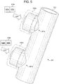
- FIGS. 5 and 6 show a fourth embodiment of a disposable set 500 including a SERS sensor 501a and a Raman spectroscopy sensor interface 501b integrated with a tube 502.
- the SERS sensor 501a includes a SERS substrate 512a (similar to the SERS substrate 312, as discussed in conjunction with FIGS. 3 and 4 ).
- the SERS sensor 501a and the Raman spectroscopy sensor interface 501b may be directly adjacent to each other and/or separated by a few centimeters (e.g., less than 4 centimeters) along the tube 502.
- the Raman spectroscopy sensor interface 501b may be located between 4 centimeters to at least 24 centimeters downstream and/or upstream from the SERS sensor 501a.
- the Raman spectroscopy sensor interface 501b includes a window and channel to facilitate a Raman spectroscopy sensor's measurement of fluid within the tube 502.
- the tube 502 includes a second port 504b from which a second cap 506b is connected.
- the second port 504b is formed in another portion of a wall of the tube 502. Similar to the first cap 506a, the second cap 506b includes a first end 514b, a second end 516, and a channel 507.
- the first end 514b includes instead a window section 505b that enables light from a Raman spectrometer to propagate to the interior of the tube 502.
- the window section 505b may be constructed from glass, quartz, or substantially transparent plastic.
- the first end 514a of the first cap 506a at the first port 504a may also include a window section 505a on the backside of the SERS substrate 512.
- This window section 505a may improve light transmission to the backside of the SERS substrate 512, thereby improving sensing accuracy.
- the SERS substrate 512 may be connected to the window section 505a via one or more posts or other connectors.
- the SERS sensor 501a operates in conjunction with a SERS sensing device 518a including a light emitter 520a and a Raman spectrometer 522a.
- the Raman spectroscopy sensor interface 501b operates in conjunction with a Raman sensing device 518b including a light emitter 520b and a Raman spectrometer 522b.
- the SERS sensor 501a and the Raman spectroscopy sensor interface 501b operate in conjunction with a single SERS (or Raman) sensing device including a light emitter and a Raman spectrometer.
- the use of a SERS sensor 501a in conjunction with a Raman spectroscopy sensor interface 501b at a similar location of the tube 502 improves fluid detection by increasing the amount of analysis performed on the fluid.
- the Raman spectroscopy sensor interface 501b enables information to be determined as to how laser light interacts with molecular vibrations, phonons, and/or other excitations in the fluid while the SERS sensor 501a provides information as to how laser light interacts with molecular vibrations, phonons, and/or other excitations on the SERS substrate 512.
- Some fluids e.g., drugs
- This configuration accordingly provides detection of more types of fluids.
- FIG. 7 shows a diagram illustrating one example fabrication process of the SERS sensing element 114 and 211 respectively of FIGS. 1 and 2 and the SERS substrates 312 and 512 respectively of FIGS. 3 and 5 .
- the sensing element and the SERS substrate include nanostructures 702 fabricated by a nanoreplica process. These nanostructures include so-called "hot spots" that concentrate an incident electromagnetic field (e.g., laser light) and effectively amplify the localized near field.
- the SERS surface with periodic nanostructure 702 (e.g., nanodomes) is generated by nanoreplica molding process utilizing silicon masters fabricated by nanoimprint lithography (as shown in FIG. 7 ).
- the enhancement factor ("EF") of the SERS substrate using these nanostructures can achieve a value as high as 10 7 .
- a silicon master wafer 704 is etched to include periodic lands 706 and valleys 708.
- a liquid UV epoxy 710 and a PET sheet 712 is disposed on the master wafer 704.
- the UV epoxy 710 and PET sheet 712 is cured using UV light to form a cured UV epoxy 714.
- the master wafer 704 is removed and the remaining structure is flipped so that a front side of the UV epoxy 714 includes lands and valleys.
- an insulating layer 716 of silicon dioxide SiO 2 is layered (e.g., deposited) on the UV epoxy 714 forming domes 702.
- silver 718 is deposited on top of the silicon dioxide layer 716. It should be appreciated that silver may be replaced with any other type of conductive metal and/or substance for SERS sensing.
- FIG. 8 shows a commonly used periodic nanopattern of the nanostructures disclosed in FIG. 7 .
- the larger circles correspond to the nanodomes 702 of FIG. 7 and the smaller circles correspond to the hot spots 802.
- the commonly used nanopattern includes two full hot spots.
- FIG. 9 shows a hybrid periodic nanostructure/pattern according to the present disclosure that increases the number of hot spots to improve the enhancement factor of the SERS substrate and/or sensing elements.
- a smaller sized nanostructure or nanodome 902 is placed within a center of the four larger nanodomes 702.
- d is the diameter of the smaller sized nanostructure 902.
- P is the distance between the centers of the larger nanodomes 702 and D is a diameter of the larger nanodomes 702.
- D is the diameter of the larger nanodomes 702.
- d is determined to be 66 nanometers.
- a disposable set in a first aspect of the present disclosure, includes a tube and a sensing member insertable into the tube, the sensing member including a first end having a first diameter and including at least one through hole positioned along a perimeter of the first end, a second end having a second diameter and including at least one through hole positioned along a perimeter of the second end, the second diameter being substantially equal to the first diameter, and a middle portion located between the first end and the second end having a diameter that is less than the first diameter, the middle portion including at least one surface enhanced Raman spectroscopy (“SERS”) sensing element.
- SERS surface enhanced Raman spectroscopy
- the SERS sensing element includes nanostructures disposed upon a plastic sheet.
- the tube includes a first interior wing configured to fix the first end of the sensing member in place within the tube.
- the tube includes a second interior wing configured to fix the second end of the sensing member in place within the tube.
- the tube includes at least one exterior wing configured to align a sensing device with the sensing member.
- the first end and the second end each include at least six through holes positioned circumferentially along the respective perimeter.
- a disposable set includes a tube and a sensing member insertable into the tube, the sensing member including a first end including a first plurality of spokes that extend from the first end to a first outer ring having a first diameter, a second end including a second plurality of spokes that extend from the second end to a second outer ring having a second diameter, the second diameter being substantially equal to the first diameter, and a middle portion located between the first end and the second end having a diameter that is less than the first diameter, the middle portion including at least one SERS sensing element.
- the spokes of the first end and the second end are compressible to enable the sensing member to be press-fitted into the tube.
- the disposable set includes a first set of spaces defined between the first end, the first plurality of spokes, and the first outer ring configured to enable fluid to flow through and a second set of spaces defined between the second end, the second plurality of spokes, and the second outer ring configured to enable the fluid to flow through.
- the tube includes a circular interior wing configured to fix the first outer ring of the sensing member in place within the tube.
- the SERS sensing element includes nanostructures arranged within a grid pattern.
- the nanostructures include a smaller sized nanostructure located within a center of four larger nanostructures.
- a disposable set includes a tube including an opening positioned along a portion of a wall of the tube and an enclosure connected to the tube at the opening, the enclosure including (i) a first end including a SERS substrate positioned to be substantially flush with an interior wall of the tube at the opening, (ii) at least one post to support the SERS substrate at the opening, (iii) a second end configured to align a sensing device with the SERS substrate, and (iv) a channel located between the first end and the second end configured to enable light from the sensing device to reach the SERS substrate.
- the channel includes a lens configured to focus the light from the sensing device on the SERS substrate.
- the second end includes an alignment key configured to align a corresponding lens of the sensing device with the SERS substrate.
- the tube includes a second opening positioned along a second portion of the wall of the tube.
- the disposable set further includes a second enclosure connected to the tube at the second opening, the second enclosure including (a) a first end including a window positioned to be substantially flush with the interior wall of the tube at the second opening, (b) a second end configured to align a second sensing device with the window, and (c) a channel located between the first end and the second end configured to enable light from the second sensing device to reach the window.
- the sensing device includes a SERS analyzer and the second sensing device includes a Raman spectroscopy analyzer.
- the second opening is located between 1 centimeter and 24 centimeters from the opening.
- any of the structure and functionality illustrated and described in connection with FIGS. 1 to 9 may be used in combination with any of the structure and functionality illustrated and described in connection with any of the other of FIGS. 1 to 9 and with any one or more of the preceding aspects.
- the disposable set of FIGS. 1 to 6 was described as being part of an IV system and could include a catheter, a connection to an infusion bag, a connection to an infusion pump, etc. It should be appreciated that the disclosed disposable set could also be included within a drug compounding system to measure fluid type and/or concentration prior to entering a compounding device and/or after exiting a compounding device. Moreover, the disposable set could be used in renal applications including, for example, hemofiltration, hemodialysis, etc.
Landscapes
- Health & Medical Sciences (AREA)
- Nuclear Medicine, Radiotherapy & Molecular Imaging (AREA)
- Physics & Mathematics (AREA)
- Life Sciences & Earth Sciences (AREA)
- Chemical & Material Sciences (AREA)
- Analytical Chemistry (AREA)
- Biochemistry (AREA)
- General Health & Medical Sciences (AREA)
- General Physics & Mathematics (AREA)
- Immunology (AREA)
- Pathology (AREA)
- Investigating, Analyzing Materials By Fluorescence Or Luminescence (AREA)
Abstract
Description
- The present disclosure relates in general to surface enhanced Raman spectroscopy, and more specifically to a sensing member within a disposable set for Raman spectroscopy sensing.
- Intravenous ("IV") therapy is typically provided to a patient using a disposable set. Previously, administrators had to confirm a fluid (e.g., drug) type, fluid concentration, or agent within a fluid to be administered by reading information on a drug container such as, for example, an infusion bag. However, administrators can misread the information on the container or forget to check the information on the container. Additionally, the fluid, agent and/or fluid/agent concentration within the container may not accurately reflect the actual fluid type or concentration. To reduce these errors and improve patient safety, sensors have been integrated within a portion of the disposable drug delivery set to provide a final verification before the fluid is infused into a patient.
- Some of these known fluid detection sensors use optical sensing to determine a drug type and/or concentration. These optical sensors include Raman spectroscopy sensors and surface enhanced Raman spectroscopy ("SERS") sensors. The sensors use light provided from an outside source, such as a laser, to detect properties in the fluid under measurement.
- Raman spectroscopy sensors measure vibrational, rotational, and other low-frequency modes of a fluid. The sensors use for example, inelastic scattering or Raman scattering of monochromatic light from a laser in the visible, near infrared, and/or near ultraviolet range. The laser light interacts with molecular vibrations, phonons, and/or other excitations in the fluid, resulting in the energy of the laser photons being shifted up or down. The shift in energy provides information about the vibrational modes in the fluid. In practice, a sample fluid is illuminated with a laser beam. Light from the illuminated spot is collected with a lens and sent through a monochromator. Wavelengths close to the laser line resulting from elastic Rayleigh scattering are filtered out while the rest of the collected light is dispersed onto a Raman spectroscopy sensor for analysis.
- SERS sensors operate under the same principles as Raman spectroscopy sensors. However, SERS sensors use a surface-sensitive detection technique that enhances Raman scattering by molecules absorbed on rough metal surfaces or nanostructures such as, for example, plasmonic-magnetic silica nanotubes. Similar to Raman spectroscopy sensors, SERS sensors use laser light to detect shifts in energy of the absorbed molecules. The use of SERS sensors requires that the sensor be in contact with the fluid under measurement. Known systems position SERS sensors within the tubing of a disposable set. However, placing the SERS sensor within the tubing reduces fluid flow, thereby frustrating infusion therapy.
- Moreover, the use of SERS sensors and Raman spectroscopy sensors requires that the laser light travel through the tubing. The plastic composition of the tubing oftentimes interferes with the laser light, reducing sensing accuracy of the Raman spectroscopy sensors and/or the SERS sensors. A need accordingly exists for a disposable set that uses Raman spectroscopy sensors and/or SERS sensors having improved fluid flow, and which is able to provide relatively interference-free laser light.
-
-
FIG. 1 shows a diagram of a disposable set including a SERS sensor disposed within a tube, according to a first embodiment of the present disclosure. -
FIG. 2 shows a diagram of a disposable set including a SERS sensor disposed within a tube, according to a second embodiment of the present disclosure. -
FIGS. 3 and4 show a diagram of a disposable set including a SERS sensor integrated with a tube, according to a third embodiment of the present disclosure. -
FIGS. 5 and6 show a diagram of a disposable set including a SERS sensor and a Raman spectroscopy sensor interface integrated with a tube, according to a fourth embodiment of the present disclosure. -
FIGS. 7A to 7E show diagrams illustrating a fabrication process of the sensing element ofFIGS. 1 and2 and the SERS substrates ofFIGS. 3 and5 , according to an example embodiment of the present disclosure. -
FIG. 8 shows a prior art nanopattern of nanostructures for the process discussed in connection withFIG. 7 . -
FIG. 9 shows a hybrid periodic nanostructure/pattern that increases a number of hot spots to improve an enhancement factor of the sensing element ofFIGS. 1 and2 and the SERS substrates ofFIGS. 3 and5 , according to an example embodiment of the present disclosure. - The present disclosure provides new and innovative configurations of SERS sensors and/or Raman spectrometry sensor interfaces configured to facilitate the detection of a fluid, concentration of a fluid, and/or a concentration of an agent within a fluid through a disposable set. In some instances, the SERS sensors are located within tubing of a disposable set. In other instances, the SERS sensors and/or Raman spectrometry sensor interfaces are positioned to be flush within an interior wall of disposable set tubing. In such a configuration, the SERS sensors and/or Raman spectrometry sensor interfaces include a wing and/or an alignment key configured to accommodate and/or connect to a lens of a Raman spectrometer.
- In an example embodiment, a disposable set includes a tube and a sensing member insertable into the tube. The sensing member is configured to include (i) a first end having a first diameter and at least one through hole positioned along a perimeter of the first end. The sensing member also includes a second end having a second diameter and including at least one through hole positioned along a perimeter of the second end, the second diameter being substantially equal to the first diameter. The sensing member further includes a middle portion located between the first end and the second end having a diameter that is less than the first diameter, the middle portion including at least one SERS sensing element.
- In another embodiment, a disposable set includes a tube including an opening positioned along a portion of a wall of the tube and an enclosure connected to the tube at the opening. The example enclosure includes a first end including a SERS substrate positioned to be substantially flush with an interior wall of the tube at the opening and at least one post to support the SERS substrate at the opening. The example enclosure also includes a second end configured to align a sensing device with the SERS substrate and a channel located between the first end and the second end configured to enable light from the sensing device to reach the SERS substrate. In this other embodiment, the disposable set may further include a second enclosure connected to the tube at the second opening. This second enclosure includes a first end including a window positioned to be substantially flush with the interior wall of the tube at the second opening, a second end configured to align a second sensing device with the window and a channel located between the first end and the second end configured to enable light from the second sensing device reach the window.
- Additional features and advantages of the disclosed SERS sensors and/or Raman spectrometry sensor interfaces are described in, and will be apparent from, the following Detailed Description and the Figures.
- The present disclosure relates in general to a disposable set that includes a SERS sensor, and in particular, to a disposable set that is integrated with an optical Raman spectroscopy interface and/or SERS sensing element for fluid verification and/or identification during IV therapy. As disclosed herein, a SERS sensor is a sensor positioned within a disposable set. The SERS sensor includes rough metal surfaces or nanostructures configured to contact or otherwise interact with molecules of a fluid flowing through the disposable cassette. The interaction of the SERS senor with the fluid molecules enhances Raman scattering to facilitate the detection of the fluid type, fluid concentration, and/or agent within a fluid by a SERS sensing (e.g., analysis and detection) device or Raman sensing device. The Raman spectroscopy interface includes a window or other structure that enables a Raman sensing device to detect properties of fluid (or agent) based on incident laser light.
- As discussed below, the Raman spectroscopy interface and/or the SERS sensor within a disposable set is configured to facilitate the detection of laser light scattering based on fluidic (or agent) properties. The detection of the scattered laser light enables the accurate detection of a wide range of drugs without affecting a flow of fluid through the disposable set. This disclosure provides different embodiments of configurations of SERS and/or Raman sensing members having one or more sensing elements and/or interfaces integrated with a disposable set.
-
FIG. 1 shows a first embodiment of adisposable set 100 for use with aSERS sensor 101. In this illustrated embodiment, thedisposable set 100 includes a tube 102 (e.g., an IV line). Thetube 102 may include any type of medical fluid material including, for example, any medical grade plastic or rubber, such as silicone, polyvinylchloride (PVC), or nylon, etc. Thetube 102 may have any diameter from a few millimeters to a few centimeters or larger. It should be appreciated thatFIG. 1 only shows a portion of thedisposable set 100 and thetube 102. For instance, thedisposable set 100 can also include a catheter, a connection to an infusion bag, a connection to an infusion pump, an air removal device, etc. - In the illustrated example, the
SERS sensor 101 includes asensing member 104 disposed within thetube 102. The sensingmember 104 may be inserted into thetube 102. Alternatively, thetube 102 may be formed or molded around the sensingmember 104. In this example, the sensingmember 104 includes afirst flange 106, asecond flange 108, and amiddle section 110. Theflanges tube 102. Such a configuration enables thesensing member 104 to be press-fittingly inserted into thetube 102 while also holding thesensing member 104 in place during use. In other examples, thesecond flange 108 may have a smaller diameter than thefirst flange 106. - The
flanges hole 112 configured to enable fluid to pass through the sensingmember 104. In the illustrated example, the sensingmember 104 includes six throughholes 112 positioned circumferentially along a perimeter of theflanges member 104 may include additional or fewer throughholes 112. Further, the diameters of the throughholes 112 may vary based on the number of throughholes 112 included within eachflange holes 112 may be based on a type of fluid (or agent) that is to pass through thetube 102. For instance, more holes and/or larger holes may be used for relatively more viscous fluids and/or more patient-critical fluids. Moreover, while the throughholes 112 are shown as being circular, in other examples they may be configured to have an oval shape, a square shape, a rectangular shape, a triangular shape, etc. - The example
middle section 110 ofFIG. 1 is configured to have a diameter that is smaller than theflanges middle section 110 includes one ormore sensing elements 114 attached to a plastic ormetallic sheet 116, which may be rolled or assembled into themiddle section 110 using a variety of methods including, for example, adhesive and/or heat shrinkable plastic. Thesensing elements 114 include a rough metal surface or nanostructures (as described in conjunction withFIGS. 7 and9 ) attached to the plastic (or metallic) sheet, which are configured to interact with molecules within the fluid to enable the acquiring of SERS measurements. In some instances, thesensing elements 114 absorb or bind to at least some molecules of a fluid under measurement. This absorption or binding enhances Raman light scattering or inelastic scattering of an incident laser light, which improves the detection of fluidic properties (e.g., vibrational, rotational, and other low-frequency modes of a fluid). The type and/or composition of thesensing elements 114 may be selected based on the fluid to be detected. - In this example, a
SERS sensing device 118 includes alight emitter 120 configured to provide light (e.g., laser light) that propagates through thetube 102 to themiddle section 110. TheSERS sensing device 110 also includes aSERS spectrometer 122 that measures interactions of molecules within the fluid with thesensing element 114 to determine properties of the fluid. TheSERS spectrometer 122 uses the detected properties to identify a fluid type and/or concentration. TheSERS spectrometer 122 may include a commercial spectrometer, e.g., from Delta Nu®, Raman Systems®, and/or Control Development, for example. - While
FIG. 1 shows only the SERS-type sensing member 104, it should be appreciated that thedisposable set 100 may also include a Raman spectroscopy sensor located upstream or downstream from sensingmember 104, as illustrated for example in connection withFIGS. 5 and6 . As discussed above, Raman spectroscopy sensing does not require a surface to detect properties of a molecule. As a result, the Raman spectroscopy sensor may be external to thetube 102. As illustrated inFIGS. 5 and6 , the use of a Raman spectroscopy sensor in conjunction with a SERS sensor enhances fluid detection precision. -
FIG. 2 shows a second embodiment of adisposable set 200 including aSERS sensor 201. In this embodiment, thedisposable set 200 includestubing 202 and sensingmember 204 withfirst end 206,second end 208, andmiddle section 210. Themiddle section 210 includes aSERS sensing element 211. Themiddle section 210 also includes astep 209 that aligns the sensing element onto a center portion of thesection 210. - The ends 206 and 208 include spokes or paddles 212 that extend from
ends outer rings 213, which compress into thetube 202 for press-fitting. For instance, thespokes 212 may be compressible to enable thesensing member 204 to be inserted or press-fitted into thetube 202. Spaces defined between ends 206 and 208,spokes 212 andouter rings 213 enable fluid to pass through the sensingmember 204. - To help fix the location of the
sensing member 204, theexample tube 202 includesinterior wings 214. Theinterior wings 214 are configured to secure or prevent thesensing member 204 from moving after insertion. In this example, theinterior wings 214 include a circular ring that extends from an interior wall of thetube 202 to contact theends interior wing 214 may include one or more latches that extend from the interior wall of the tubing. WhileFIG. 2 shows aninterior wing 214 for eachend tube 202 may include only oneinterior wing 214. - The
example tube 202 ofFIG. 2 also includesexterior wings 216. As discussed above, a SERS sensing device 218 (including alight emitter 220 and a Raman spectrometer 222) is placed adjacent to thesensing member 204 exterior to thetube 202 to provide SERS sensing and analysis. The exampleexterior wings 216 extend from an exterior wall of thetube 202 to align a lens of theSERS sensing device 218 with the sensingmember 204. In this embodiment, theexterior wings 216 are located in proximity to theends exterior wings 216 may be located at other portions of thetube 202 based on the type of Raman spectrometer and/or lens used. Further, dimensions of theexterior wings 216 may be based on the type of Raman spectrometer and/or lens. - While the
interior wings 214 and theexterior wings 216 are shown as being integrated with thetube 202, it should be appreciated that in other examples, thewings tube 202. In these examples, thewings tube 202 using adhesives, pressure bonding, heat staking, etc. Additionally, in some embodiments, thewings wings -
FIGS. 3 and4 show a third embodiment of adisposable set 300 including aSERS sensor 301 integrated with atube 302. In this embodiment, thetube 302 includesport 304 defining an opening formed in a portion of a wall of thetube 302. Acap 306 is connected to thetube 302 at theport 304. The connection of theport 304 andcap 306 may be made by induction welding and/or any other method to create a seal between the wall of thetubing 302 and thecap 306. - The
example cap 306 includes afirst end 308 and asecond end 310. Thefirst end 308 faces an interior of thetube 302. Thesecond end 310 faces away from the tube and may include analignment key 311 for a SERS sensing device 318 (including alight emitter 320 and a Raman spectrometer 322). As shown inFIG. 4 , thefirst end 308 incudes aSERS substrate 312 that is positioned to be substantially flush with the interior wall of thetube 302. TheSERS substrate 312 may be supported by one ormore posts 314 to prevent the substrate from moving during use. Similar to thesensing element FIGS. 1 and2 , theSERS substrate 312 ofFIG. 3 includes rough metal surfaces or nanostructures disposed on a plastic and/or metallic sheet (described in conjunction withFIGS. 7 and9 ). - The configuration shown in
FIGS. 3 and4 enables theSERS substrate 312 to be backlight by thelight emitter 320 for fluid molecule analysis while at the same time reducing the amount of area within thetube 302 used by the sensor. In comparison, thesensing members FIGS. 1 and2 consume a relatively large volume within the tube. While throughholes 112 and paddles 212 reduce fluid restriction, the volume of themembers FIG. 3 instead locates theSERS substrate 312 along a wall of thetube 302, thereby keeping the channel of thetube 302 relatively free of components. In some instances, theSERS substrate 312 may extend some distance (e.g., 0.1 to 10 millimeters) from the interior wall of the tube to increase the amount of contact with the fluid. - To enable light to reach the
SERS substrate 312, theexample cap 306 ofFIG. 3 includes achannel 316 that extends from thefirst end 308 to thesecond end 310. The dimensions of the channel may vary based on the alignment key of thesecond end 310 and the size of theSERS substrate 312. Thealignment key 311 functions as a window to enable light from theSERS sensing device 318 to travel through thechannel 316 to theSERS substrate 312. In some embodiments, thechannel 316 may include one or more lens to focus light on theSERS substrate 312. -
FIGS. 5 and6 show a fourth embodiment of adisposable set 500 including aSERS sensor 501a and a Ramanspectroscopy sensor interface 501b integrated with atube 502. In this embodiment, theSERS sensor 501a includes a SERS substrate 512a (similar to theSERS substrate 312, as discussed in conjunction withFIGS. 3 and4 ). As shown inFIGS. 5 and6 , theSERS sensor 501a and the Ramanspectroscopy sensor interface 501b may be directly adjacent to each other and/or separated by a few centimeters (e.g., less than 4 centimeters) along thetube 502. In other embodiments, the Ramanspectroscopy sensor interface 501b may be located between 4 centimeters to at least 24 centimeters downstream and/or upstream from theSERS sensor 501a. - The Raman
spectroscopy sensor interface 501b includes a window and channel to facilitate a Raman spectroscopy sensor's measurement of fluid within thetube 502. To accommodate this Ramanspectroscopy sensor interface 501b, thetube 502 includes asecond port 504b from which asecond cap 506b is connected. Thesecond port 504b is formed in another portion of a wall of thetube 502. Similar to thefirst cap 506a, thesecond cap 506b includes a first end 514b, a second end 516, and achannel 507. However, because Raman spectroscopy sensors do not require a sensing element that contacts the fluid, the first end 514b includes instead awindow section 505b that enables light from a Raman spectrometer to propagate to the interior of thetube 502. To reduce interference, thewindow section 505b may be constructed from glass, quartz, or substantially transparent plastic. - In some instances, the
first end 514a of thefirst cap 506a at thefirst port 504a may also include awindow section 505a on the backside of theSERS substrate 512. Thiswindow section 505a may improve light transmission to the backside of theSERS substrate 512, thereby improving sensing accuracy. TheSERS substrate 512 may be connected to thewindow section 505a via one or more posts or other connectors. - The
SERS sensor 501a operates in conjunction with aSERS sensing device 518a including alight emitter 520a and aRaman spectrometer 522a. The Ramanspectroscopy sensor interface 501b operates in conjunction with aRaman sensing device 518b including alight emitter 520b and aRaman spectrometer 522b. Alternatively, theSERS sensor 501a and the Ramanspectroscopy sensor interface 501b operate in conjunction with a single SERS (or Raman) sensing device including a light emitter and a Raman spectrometer. - It should be appreciated that the use of a
SERS sensor 501a in conjunction with a Ramanspectroscopy sensor interface 501b at a similar location of thetube 502 improves fluid detection by increasing the amount of analysis performed on the fluid. For instance, the Ramanspectroscopy sensor interface 501b enables information to be determined as to how laser light interacts with molecular vibrations, phonons, and/or other excitations in the fluid while theSERS sensor 501a provides information as to how laser light interacts with molecular vibrations, phonons, and/or other excitations on theSERS substrate 512. Some fluids (e.g., drugs) that may not be easily detectable by one type of sensor may be more readily detected by the other sensor. This configuration accordingly provides detection of more types of fluids. -
FIG. 7 (collectively 7A to 7E) shows a diagram illustrating one example fabrication process of theSERS sensing element FIGS. 1 and2 and theSERS substrates FIGS. 3 and5 . As shown inFIGS. 7A to 7E , the sensing element and the SERS substrate (collectively structure 700) includenanostructures 702 fabricated by a nanoreplica process. These nanostructures include so-called "hot spots" that concentrate an incident electromagnetic field (e.g., laser light) and effectively amplify the localized near field. The SERS surface with periodic nanostructure 702 (e.g., nanodomes) is generated by nanoreplica molding process utilizing silicon masters fabricated by nanoimprint lithography (as shown inFIG. 7 ). The enhancement factor ("EF") of the SERS substrate using these nanostructures can achieve a value as high as 107. - As shown in
FIG. 7A , asilicon master wafer 704 is etched to includeperiodic lands 706 andvalleys 708. InFIG. 7B , aliquid UV epoxy 710 and aPET sheet 712 is disposed on themaster wafer 704. InFIG. 7C , theUV epoxy 710 andPET sheet 712 is cured using UV light to form a curedUV epoxy 714. InFIG. 7D , themaster wafer 704 is removed and the remaining structure is flipped so that a front side of theUV epoxy 714 includes lands and valleys. InFIG. 7D , an insulatinglayer 716 of silicon dioxide SiO2 is layered (e.g., deposited) on theUV epoxy 714 formingdomes 702. InFIG. 7E ,silver 718 is deposited on top of thesilicon dioxide layer 716. It should be appreciated that silver may be replaced with any other type of conductive metal and/or substance for SERS sensing. -
FIG. 8 shows a commonly used periodic nanopattern of the nanostructures disclosed inFIG. 7 . In this example, the larger circles correspond to thenanodomes 702 ofFIG. 7 and the smaller circles correspond to thehot spots 802. For any square defined by the centers of the nanodomes, the commonly used nanopattern includes two full hot spots. -
FIG. 9 shows a hybrid periodic nanostructure/pattern according to the present disclosure that increases the number of hot spots to improve the enhancement factor of the SERS substrate and/or sensing elements. In this embodiment, a smaller sized nanostructure ornanodome 902 is placed within a center of the fourlarger nanodomes 702. In order to maintain the distance between adjacent nanostructures, equation (1) is used:
- In equation (1) d is the diameter of the smaller
sized nanostructure 902. P is the distance between the centers of the larger nanodomes 702 and D is a diameter of thelarger nanodomes 702. In an example where D is equal to 300 nanometers, P is equal to 400 nanometers, d is determined to be 66 nanometers. As a result of this configuration, the number ofhot spots 802 within the dotted square has been tripled from two (in the case of the prior art example) to six for the same covered area. This configuration accordingly improves the signal or accuracy of the SERS substrates and sensing elements. - To the above ends, and without limiting the following description, in a first aspect of the present disclosure, a disposable set includes a tube and a sensing member insertable into the tube, the sensing member including a first end having a first diameter and including at least one through hole positioned along a perimeter of the first end, a second end having a second diameter and including at least one through hole positioned along a perimeter of the second end, the second diameter being substantially equal to the first diameter, and a middle portion located between the first end and the second end having a diameter that is less than the first diameter, the middle portion including at least one surface enhanced Raman spectroscopy ("SERS") sensing element.
- In accordance with a second aspect of the present disclosure, which may be used in combination with the first aspect, the SERS sensing element includes nanostructures disposed upon a plastic sheet.
- In accordance with a third aspect of the present disclosure, which may be used in combination with any one or more of the preceding aspects, the tube includes a first interior wing configured to fix the first end of the sensing member in place within the tube.
- In accordance with a fourth aspect of the present disclosure, which may be used in combination with any one or more of the preceding aspects, the tube includes a second interior wing configured to fix the second end of the sensing member in place within the tube.
- In accordance with a fifth aspect of the present disclosure, which may be used in combination with any one or more of the preceding aspects, the tube includes at least one exterior wing configured to align a sensing device with the sensing member.
- In accordance with a sixth aspect of the present disclosure, which may be used in combination with any one or more of the preceding aspects, the first end and the second end each include at least six through holes positioned circumferentially along the respective perimeter.
- In accordance with a seventh aspect of the present disclosure, which may be used in combination with any one or more of the preceding aspects, a disposable set includes a tube and a sensing member insertable into the tube, the sensing member including a first end including a first plurality of spokes that extend from the first end to a first outer ring having a first diameter, a second end including a second plurality of spokes that extend from the second end to a second outer ring having a second diameter, the second diameter being substantially equal to the first diameter, and a middle portion located between the first end and the second end having a diameter that is less than the first diameter, the middle portion including at least one SERS sensing element.
- In accordance with a eighth aspect of the present disclosure, which may be used in combination with any one or more of the preceding aspects, the spokes of the first end and the second end are compressible to enable the sensing member to be press-fitted into the tube.
- In accordance with a ninth aspect of the present disclosure, which may be used in combination with any one or more of the preceding aspects, the disposable set includes a first set of spaces defined between the first end, the first plurality of spokes, and the first outer ring configured to enable fluid to flow through and a second set of spaces defined between the second end, the second plurality of spokes, and the second outer ring configured to enable the fluid to flow through.
- In accordance with a tenth aspect of the present disclosure, which may be used in combination with any one or more of the preceding aspects, the tube includes a circular interior wing configured to fix the first outer ring of the sensing member in place within the tube.
- In accordance with a eleventh aspect of the present disclosure, which may be used in combination with any one or more of the preceding aspects, the SERS sensing element includes nanostructures arranged within a grid pattern.
- In accordance with a twelfth aspect of the present disclosure, which may be used in combination with any one or more of the preceding aspects, the nanostructures include a smaller sized nanostructure located within a center of four larger nanostructures.
- In accordance with a thirteenth aspect of the present disclosure, which may be used in combination with any one or more of the preceding aspects, the smaller sized nanostructure has a diameter d according to the following equation

- In accordance with a fourteenth aspect of the present disclosure, which may be used in combination with any one or more of the preceding aspects, a disposable set includes a tube including an opening positioned along a portion of a wall of the tube and an enclosure connected to the tube at the opening, the enclosure including (i) a first end including a SERS substrate positioned to be substantially flush with an interior wall of the tube at the opening, (ii) at least one post to support the SERS substrate at the opening, (iii) a second end configured to align a sensing device with the SERS substrate, and (iv) a channel located between the first end and the second end configured to enable light from the sensing device to reach the SERS substrate.
- In accordance with a fifteenth aspect of the present disclosure, which may be used in combination with any one or more of the preceding aspects, the channel includes a lens configured to focus the light from the sensing device on the SERS substrate.
- In accordance with a sixteenth aspect of the present disclosure, which may be used in combination with any one or more of the preceding aspects, the second end includes an alignment key configured to align a corresponding lens of the sensing device with the SERS substrate.
- In accordance with a seventeenth aspect of the present disclosure, which may be used in combination with any one or more of the preceding aspects, the tube includes a second opening positioned along a second portion of the wall of the tube.
- In accordance with a eighteenth aspect of the present disclosure, which may be used in combination with any one or more of the preceding aspects, the disposable set further includes a second enclosure connected to the tube at the second opening, the second enclosure including (a) a first end including a window positioned to be substantially flush with the interior wall of the tube at the second opening, (b) a second end configured to align a second sensing device with the window, and (c) a channel located between the first end and the second end configured to enable light from the second sensing device to reach the window.
- In accordance with a nineteenth aspect of the present disclosure, which may be used in combination with any one or more of the preceding aspects, the sensing device includes a SERS analyzer and the second sensing device includes a Raman spectroscopy analyzer.
- In accordance with a twentieth aspect of the present disclosure, which may be used in combination with any one or more of the preceding aspects, the second opening is located between 1 centimeter and 24 centimeters from the opening.
- In accordance with a twenty-first aspect of the present disclosure, any of the structure and functionality illustrated and described in connection with
FIGS. 1 to 9 may be used in combination with any of the structure and functionality illustrated and described in connection with any of the other ofFIGS. 1 to 9 and with any one or more of the preceding aspects. - It should be understood that various changes and modifications to the example embodiments described herein will be apparent to those skilled in the art. Such changes and modifications can be made without departing from the spirit and scope of the present subject matter and without diminishing its intended advantages. It is therefore intended that such changes and modifications be covered by the appended claims.
- For example the disposable set of
FIGS. 1 to 6 was described as being part of an IV system and could include a catheter, a connection to an infusion bag, a connection to an infusion pump, etc. It should be appreciated that the disclosed disposable set could also be included within a drug compounding system to measure fluid type and/or concentration prior to entering a compounding device and/or after exiting a compounding device. Moreover, the disposable set could be used in renal applications including, for example, hemofiltration, hemodialysis, etc.
Claims (16)
- A disposable set (300, 500) including:a tube (302, 502) including an opening (304, 504) positioned along a portion of a wall of the tube; andan enclosure (306, 506) connected to the tube at the opening, the enclosure including:(i) a first end (308, 514) including a surface enhanced Raman spectroscopy ("SERS") substrate (312, 512) positioned to be substantially flush with an interior wall of the tube at the opening,(ii) at least one post (314) to support the SERS substrate at the opening,(iii) a second end (310, 516) configured to align a sensing device with the SERS substrate, and(iv) a channel (316, 507) located between the first end and the second end configured to enable light from the sensing device to reach the SERS substrate.
- The disposable set of Claim 1, wherein the channel includes a lens configured to focus the light from the sensing device on the SERS substrate.
- The disposable set of Claims 1 or 2, wherein the second end includes an alignment key configured to align a corresponding lens of the sensing device with the SERS substrate.
- The disposable set of Claims 1, 2, or 3, wherein the sensing device includes at least one of a light emitter and a Raman spectrometer.
- The disposable set of Claims 1, 2, or 3, wherein the tube includes a second opening positioned along a second portion of the wall of the tube.
- The disposable set of Claim 5, wherein the disposable set further includes a second enclosure connected to the tube at the second opening, the second enclosure including:(a) a first end including a window positioned to be substantially flush with the interior wall of the tube at the second opening,(b) a second end configured to align a second sensing device with the window; and(c) a channel located between the first end and the second end configured to enable light from the second sensing device to reach the window.
- The disposable set of Claim 6, wherein the sensing device includes a SERS analyzer and the second sensing device includes a Raman spectroscopy analyzer.
- The disposable set of Claims 5, 6, or 7, wherein the second opening is located between 1 centimeter and 24 centimeters from the opening.
- A surface enhanced Raman spectroscopy ("SERS") sensor (391, 501) including:(i) a first end (308, 514) including a SERS substrate (312, 512),(ii) at least one post (314) to support the SERS substrate,(iii) a second end (310, 516) configured to align a sensing device with the SERS substrate, and(iv) a channel (316, 507) located between the first end and the second end configured to enable light from the sensing device to reach the SERS substrate.
- The SERS sensor of Claim 9, wherein the SERS substrate includes a rough metal surface.
- The SERS sensor of Claim 9, wherein the SERS substrate includes nanostructures disposed on a plastic or metallic sheet.
- The SERS sensor of Claim 11, wherein the nanostructures are arranged in a two-dimensional grid including a small nanodome placed between four large nanodomes.
- The SERS sensor of Claim 12, wherein the nanostructures include hot spots placed between each pair of the four large nanodomes and between each of the four large nanodomes and the small nanodome, wherein the hot spots are configured to concentrate an incident electromagnetic field.
- The SERS sensor of Claims 9, 10, or 11, wherein the sensing device includes at least one of a light emitter and a Raman spectrometer.
- The SERS sensor of Claim 14, wherein the Raman spectrometer is configured to detect light provided by the light emitter that is reflected from the SERS substrate to determine a property of a fluid that is in contact with the SERS substrate.
- The SERS sensor of Claim 15, wherein the Raman spectrometer is configured to determine at least one of a fluid type and concentration of the fluid that is in contact with the SERS substrate based on the determined property.
Applications Claiming Priority (2)
| Application Number | Priority Date | Filing Date | Title |
|---|---|---|---|
| US201361875447P | 2013-09-09 | 2013-09-09 | |
| EP14771477.8A EP3044570B1 (en) | 2013-09-09 | 2014-09-08 | Disposable sets including surface enhanced raman spectroscopy sensors |
Related Parent Applications (1)
| Application Number | Title | Priority Date | Filing Date |
|---|---|---|---|
| EP14771477.8A Division EP3044570B1 (en) | 2013-09-09 | 2014-09-08 | Disposable sets including surface enhanced raman spectroscopy sensors |
Publications (1)
| Publication Number | Publication Date |
|---|---|
| EP3287770A1 true EP3287770A1 (en) | 2018-02-28 |
Family
ID=51582528
Family Applications (2)
| Application Number | Title | Priority Date | Filing Date |
|---|---|---|---|
| EP14771477.8A Not-in-force EP3044570B1 (en) | 2013-09-09 | 2014-09-08 | Disposable sets including surface enhanced raman spectroscopy sensors |
| EP17195282.3A Withdrawn EP3287770A1 (en) | 2013-09-09 | 2014-09-08 | Disposable sets including raman sensors |
Family Applications Before (1)
| Application Number | Title | Priority Date | Filing Date |
|---|---|---|---|
| EP14771477.8A Not-in-force EP3044570B1 (en) | 2013-09-09 | 2014-09-08 | Disposable sets including surface enhanced raman spectroscopy sensors |
Country Status (5)
| Country | Link |
|---|---|
| US (1) | US10088423B2 (en) |
| EP (2) | EP3044570B1 (en) |
| AU (2) | AU2014317928B2 (en) |
| CA (1) | CA2923458A1 (en) |
| WO (1) | WO2015035285A1 (en) |
Citations (2)
| Publication number | Priority date | Publication date | Assignee | Title |
|---|---|---|---|---|
| CN102279175A (en) * | 2011-06-28 | 2011-12-14 | 吉林大学 | Device for directionally emitting enhanced Raman spectrums by utilizing surface plasmas |
| US20120276549A1 (en) * | 2011-04-29 | 2012-11-01 | The Board of Trustees of the University of Illinois SRU Biosystems, Inc. | Photonic biosensors incorporated into tubing, methods of manufacture and instruments for analyziing the biosensors |
Family Cites Families (5)
| Publication number | Priority date | Publication date | Assignee | Title |
|---|---|---|---|---|
| US6623977B1 (en) * | 1999-11-05 | 2003-09-23 | Real-Time Analyzers, Inc. | Material for surface-enhanced Raman spectroscopy, and SER sensors and method for preparing same |
| US7713849B2 (en) | 2004-08-20 | 2010-05-11 | Illuminex Corporation | Metallic nanowire arrays and methods for making and using same |
| JP2014509744A (en) | 2011-03-25 | 2014-04-21 | イムラ アメリカ インコーポレイテッド | Surface enhanced Raman scattering apparatus and method |
| US9019495B2 (en) * | 2012-07-31 | 2015-04-28 | Hewlett-Packard Development Company, L.P. | Apparatus for performing spectroscopy having a porous membrane |
| US8670119B1 (en) * | 2013-01-30 | 2014-03-11 | Hewlett-Packard Development Company, L.P. | Apparatus having surface-enhanced spectroscopy modules |
-
2014
- 2014-09-08 EP EP14771477.8A patent/EP3044570B1/en not_active Not-in-force
- 2014-09-08 US US15/036,004 patent/US10088423B2/en active Active
- 2014-09-08 CA CA2923458A patent/CA2923458A1/en not_active Abandoned
- 2014-09-08 AU AU2014317928A patent/AU2014317928B2/en not_active Ceased
- 2014-09-08 WO PCT/US2014/054508 patent/WO2015035285A1/en not_active Ceased
- 2014-09-08 EP EP17195282.3A patent/EP3287770A1/en not_active Withdrawn
-
2017
- 2017-09-19 AU AU2017232074A patent/AU2017232074A1/en not_active Abandoned
Patent Citations (2)
| Publication number | Priority date | Publication date | Assignee | Title |
|---|---|---|---|---|
| US20120276549A1 (en) * | 2011-04-29 | 2012-11-01 | The Board of Trustees of the University of Illinois SRU Biosystems, Inc. | Photonic biosensors incorporated into tubing, methods of manufacture and instruments for analyziing the biosensors |
| CN102279175A (en) * | 2011-06-28 | 2011-12-14 | 吉林大学 | Device for directionally emitting enhanced Raman spectrums by utilizing surface plasmas |
Non-Patent Citations (1)
| Title |
|---|
| CHARLES J. CHOI ET AL: "Biochemical sensor tubing for point-of-care monitoring of intravenous drugs and metabolites", LAB ON A CHIP, vol. 12, no. 3, 12 December 2012 (2012-12-12), pages 574 - 581, XP055428814, ISSN: 1473-0197, DOI: 10.1039/C2LC20586F * |
Also Published As
| Publication number | Publication date |
|---|---|
| AU2017232074A1 (en) | 2017-10-12 |
| AU2014317928B2 (en) | 2017-06-22 |
| US20170199128A1 (en) | 2017-07-13 |
| US10088423B2 (en) | 2018-10-02 |
| CA2923458A1 (en) | 2015-03-12 |
| AU2014317928A1 (en) | 2016-03-24 |
| EP3044570A1 (en) | 2016-07-20 |
| WO2015035285A1 (en) | 2015-03-12 |
| EP3044570B1 (en) | 2017-11-08 |
Similar Documents
| Publication | Publication Date | Title |
|---|---|---|
| Ro et al. | Integrated light collimating system for extended optical-path-length absorbance detection in microchip-based capillary electrophoresis | |
| US9272126B2 (en) | Photonic biosensors incorporated into tubing, methods of manufacture and instruments for analyzing the biosensors | |
| CN1751239B (en) | Blood analysis device and blood analysis method | |
| Zheng et al. | Micro coulter counters with platinum black electroplated electrodes for human blood cell sensing | |
| CN104483498A (en) | Sensing chip and preparation method thereof | |
| CN109328229A (en) | Gene sequencing chip and its installing frame | |
| Cooksey et al. | Dynamic measurement of nanoflows: realization of an optofluidic flow meter to the nanoliter-per-minute scale | |
| WO2017069139A1 (en) | Immunological measurement device | |
| CN106198327A (en) | A kind of liquid particles detection device | |
| JP2004340702A (en) | Microchip and liquid detection method | |
| Bryan et al. | A multiplex “Disposable Photonics” biosensor platform and its application to antibody profiling in upper respiratory disease | |
| US20230296603A1 (en) | Development of a smartphone-based biosensor device for detecting sars-cov-2 antigens in body fluids using localized surface plasmon resonance (lspr) | |
| AU2014317928B2 (en) | Disposable sets including Raman sensors | |
| CN110914672A (en) | Optical test platform | |
| Qu et al. | Microfluidic chip with fiber-tip sensors for synchronously monitoring concentration and temperature of glucose solutions | |
| Ma et al. | A hybrid microdevice with a thin PDMS membrane on the detection window for UV absorbance detection | |
| Chandra Roy et al. | On chip optofluidic low‐pressure monitoring device | |
| Kang | Assessment of blood biophysical properties using pressure sensing with micropump and microfluidic comparator | |
| Yoon et al. | Microfluidic airborne metal particle sensor using oil microcirculation for real-time and continuous monitoring of metal particle emission | |
| CN103284731B (en) | Light-resistant blood collection tube | |
| JP4371745B2 (en) | Microreactor for optical measurement and optical measurement method using the same | |
| CN107449712B (en) | Method and device for detecting reagent in channel and cell analyzer system | |
| CN110869741A (en) | Analysis device and flow path plate | |
| Cheng et al. | Microfluidic Preconcentration Chip with Self-Assembled Chemical Modified Surface for Trace Carbonyl Compounds Detection | |
| CN209992451U (en) | A Microfluidic Ultraviolet Oxidation Device for Organic Nitrogen Analysis |
Legal Events
| Date | Code | Title | Description |
|---|---|---|---|
| PUAI | Public reference made under article 153(3) epc to a published international application that has entered the european phase |
Free format text: ORIGINAL CODE: 0009012 |
|
| STAA | Information on the status of an ep patent application or granted ep patent |
Free format text: STATUS: REQUEST FOR EXAMINATION WAS MADE |
|
| 17P | Request for examination filed |
Effective date: 20171006 |
|
| AC | Divisional application: reference to earlier application |
Ref document number: 3044570 Country of ref document: EP Kind code of ref document: P |
|
| AK | Designated contracting states |
Kind code of ref document: A1 Designated state(s): AL AT BE BG CH CY CZ DE DK EE ES FI FR GB GR HR HU IE IS IT LI LT LU LV MC MK MT NL NO PL PT RO RS SE SI SK SM TR |
|
| STAA | Information on the status of an ep patent application or granted ep patent |
Free format text: STATUS: THE APPLICATION IS DEEMED TO BE WITHDRAWN |
|
| 18D | Application deemed to be withdrawn |
Effective date: 20180829 |