EP3287707A1 - Fan guard assembly and outdoor unit having the same - Google Patents
Fan guard assembly and outdoor unit having the same Download PDFInfo
- Publication number
- EP3287707A1 EP3287707A1 EP17168834.4A EP17168834A EP3287707A1 EP 3287707 A1 EP3287707 A1 EP 3287707A1 EP 17168834 A EP17168834 A EP 17168834A EP 3287707 A1 EP3287707 A1 EP 3287707A1
- Authority
- EP
- European Patent Office
- Prior art keywords
- hub
- rib
- outdoor unit
- fan
- motor
- Prior art date
- Legal status (The legal status is an assumption and is not a legal conclusion. Google has not performed a legal analysis and makes no representation as to the accuracy of the status listed.)
- Granted
Links
Images




Classifications
-
- F—MECHANICAL ENGINEERING; LIGHTING; HEATING; WEAPONS; BLASTING
- F04—POSITIVE - DISPLACEMENT MACHINES FOR LIQUIDS; PUMPS FOR LIQUIDS OR ELASTIC FLUIDS
- F04D—NON-POSITIVE-DISPLACEMENT PUMPS
- F04D29/00—Details, component parts, or accessories
- F04D29/70—Suction grids; Strainers; Dust separation; Cleaning
- F04D29/701—Suction grids; Strainers; Dust separation; Cleaning especially adapted for elastic fluid pumps
- F04D29/703—Suction grids; Strainers; Dust separation; Cleaning especially adapted for elastic fluid pumps specially for fans, e.g. fan guards
-
- F—MECHANICAL ENGINEERING; LIGHTING; HEATING; WEAPONS; BLASTING
- F04—POSITIVE - DISPLACEMENT MACHINES FOR LIQUIDS; PUMPS FOR LIQUIDS OR ELASTIC FLUIDS
- F04D—NON-POSITIVE-DISPLACEMENT PUMPS
- F04D19/00—Axial-flow pumps
- F04D19/002—Axial flow fans
-
- F—MECHANICAL ENGINEERING; LIGHTING; HEATING; WEAPONS; BLASTING
- F04—POSITIVE - DISPLACEMENT MACHINES FOR LIQUIDS; PUMPS FOR LIQUIDS OR ELASTIC FLUIDS
- F04D—NON-POSITIVE-DISPLACEMENT PUMPS
- F04D25/00—Pumping installations or systems
- F04D25/02—Units comprising pumps and their driving means
- F04D25/06—Units comprising pumps and their driving means the pump being electrically driven
- F04D25/0693—Details or arrangements of the wiring
-
- F—MECHANICAL ENGINEERING; LIGHTING; HEATING; WEAPONS; BLASTING
- F04—POSITIVE - DISPLACEMENT MACHINES FOR LIQUIDS; PUMPS FOR LIQUIDS OR ELASTIC FLUIDS
- F04D—NON-POSITIVE-DISPLACEMENT PUMPS
- F04D29/00—Details, component parts, or accessories
- F04D29/26—Rotors specially for elastic fluids
- F04D29/32—Rotors specially for elastic fluids for axial flow pumps
- F04D29/325—Rotors specially for elastic fluids for axial flow pumps for axial flow fans
-
- F—MECHANICAL ENGINEERING; LIGHTING; HEATING; WEAPONS; BLASTING
- F04—POSITIVE - DISPLACEMENT MACHINES FOR LIQUIDS; PUMPS FOR LIQUIDS OR ELASTIC FLUIDS
- F04D—NON-POSITIVE-DISPLACEMENT PUMPS
- F04D29/00—Details, component parts, or accessories
- F04D29/26—Rotors specially for elastic fluids
- F04D29/32—Rotors specially for elastic fluids for axial flow pumps
- F04D29/325—Rotors specially for elastic fluids for axial flow pumps for axial flow fans
- F04D29/329—Details of the hub
-
- F—MECHANICAL ENGINEERING; LIGHTING; HEATING; WEAPONS; BLASTING
- F24—HEATING; RANGES; VENTILATING
- F24F—AIR-CONDITIONING; AIR-HUMIDIFICATION; VENTILATION; USE OF AIR CURRENTS FOR SCREENING
- F24F1/00—Room units for air-conditioning, e.g. separate or self-contained units or units receiving primary air from a central station
- F24F1/06—Separate outdoor units, e.g. outdoor unit to be linked to a separate room comprising a compressor and a heat exchanger
- F24F1/38—Fan details of outdoor units, e.g. bell-mouth shaped inlets or fan mountings
-
- F—MECHANICAL ENGINEERING; LIGHTING; HEATING; WEAPONS; BLASTING
- F24—HEATING; RANGES; VENTILATING
- F24F—AIR-CONDITIONING; AIR-HUMIDIFICATION; VENTILATION; USE OF AIR CURRENTS FOR SCREENING
- F24F1/00—Room units for air-conditioning, e.g. separate or self-contained units or units receiving primary air from a central station
- F24F1/06—Separate outdoor units, e.g. outdoor unit to be linked to a separate room comprising a compressor and a heat exchanger
- F24F1/40—Vibration or noise prevention at outdoor units
-
- F—MECHANICAL ENGINEERING; LIGHTING; HEATING; WEAPONS; BLASTING
- F24—HEATING; RANGES; VENTILATING
- F24F—AIR-CONDITIONING; AIR-HUMIDIFICATION; VENTILATION; USE OF AIR CURRENTS FOR SCREENING
- F24F1/00—Room units for air-conditioning, e.g. separate or self-contained units or units receiving primary air from a central station
- F24F1/06—Separate outdoor units, e.g. outdoor unit to be linked to a separate room comprising a compressor and a heat exchanger
- F24F1/46—Component arrangements in separate outdoor units
- F24F1/48—Component arrangements in separate outdoor units characterised by air airflow, e.g. inlet or outlet airflow
-
- F—MECHANICAL ENGINEERING; LIGHTING; HEATING; WEAPONS; BLASTING
- F24—HEATING; RANGES; VENTILATING
- F24F—AIR-CONDITIONING; AIR-HUMIDIFICATION; VENTILATION; USE OF AIR CURRENTS FOR SCREENING
- F24F1/00—Room units for air-conditioning, e.g. separate or self-contained units or units receiving primary air from a central station
- F24F1/06—Separate outdoor units, e.g. outdoor unit to be linked to a separate room comprising a compressor and a heat exchanger
- F24F1/56—Casing or covers of separate outdoor units, e.g. fan guards
Definitions
- the present invention relates to a fan guard assembly having an improved structure for providing improved performance and an outdoor unit having the same.
- an air conditioner is a device removing dust, and the like in the air while controlling a distribution of temperature, humidity, an air current, and the like, appropriate for human activities using a freezing cycle.
- Main components configuring the freezing cycle include a compressor, a condenser, an evaporator, a blower fan, and the like.
- An air conditioner is referred to as a split type air conditioner when an indoor unit and an outdoor unit are installed separately and is referred to as an integrated air conditioner when the indoor unit and the outdoor unit are installed together in a single cabinet.
- the split type air conditioner is composed of the indoor unit having the evaporator and the fan and the outdoor unit having the compressor, the condenser, and the fan.
- the outdoor unit of the split type air conditioner has a motor for rotating the fan and a motor bracket for supporting the motor. Considering a position where the motor and the motor bracket are installed in the outdoor unit, it is common that the motor and the motor bracket are installed between the condenser and the fan. Describing the flow of air in the installation structure, air introduced into an inlet sequentially passes through the condenser, the motor bracket, and the fan, and then is discharged through an outlet.
- Exemplary embodiments of the present invention overcome the above disadvantages and other disadvantages not described above. Also, the present invention is not required to overcome the disadvantages described above, and an exemplary embodiment of the present invention may not overcome any of the problems described above.
- the present disclosure provides an outdoor unit capable of decreasing a flow resistance of air flowing from a blower fan.
- the present disclosure also provides a fan guard assembly capable of securing rigidity for stably supporting a blower fan and a motor.
- an outdoor unit includes: a cabinet; a bell mouth provided in the cabinet; a fan guard provided at an outlet of the bell mouth; and a fan motor assembly fixed to the fan guard.
- the fan guard may include: a hub located at a center of the outlet and having the fan motor assembly fixed thereto; and a rib connecting between the hub and the cabinet.
- the fan motor assembly may include: a motor fixed to the hub; and a blower fan driven by the motor.
- a height of the rib may increase outwardly from the hub.
- the rib may include a first end surface corresponding to a position where it is connected to the hub and a second end surface corresponding to a tip of a blade of the blower fan, the first end surface may have a height of 0.02 to 0.09 times a distance L from a center of the hub to the tip of the blade, and the second end surface may have a height of 0.04 to 0.2 times the distance L.
- the rib further may include a third end surface located between the first and second end surfaces, at the same distance from the first and second end surfaces, respectively, and the third end surface may have a height of 0.03 to 0.14 times the distance L.
- a cross section of the rib may have a tilt angle increasing as being far away from the hub with respect to a driving shaft of the motor.
- the rib may include a first end surface corresponding to a position where it is connected to the hub and a second end surface corresponding to a tip of a blade of the blower fan, the first end surface may have a tilt angle of 10° to 30°, and the second end surface may have a tilt angle of 20° to 40°.
- the rib may further include a third end surface located between the first and second end surfaces, at the same distance from the first and second end surfaces, respectively, and the third end surface may have a tilt angle of 15° to 35°.
- the rib may include: a plurality of first ribs radially provided from the hub; and a plurality of second ribs spaced from the hub in a circumferential direction to be connected to the first ribs.
- the plurality of first ribs may include: a first rib having a height increasing outwardly from the hub; and an auxiliary rib connecting between the second rib and the cabinet.
- a tip of the first rib may be located on the same plane and a rear end of the first rib may have a height increasing toward the fan motor assembly.
- a transverse section of the first rib may have a fan shape or an airfoil.
- the hub may have an insertion portion into which at least a part of the motor is inserted.
- the hub may have a fastening portion protruding from an outer circumferential surface of the hub, and the fastening portion may have a fastening hole fastened to the motor.
- the rib may have an accommodating portion accommodating an electric wire connected to the motor.
- the bell mouth may have a through hole through which the electric wire penetrates.
- a fan guard assembly includes: a front panel having an outlet; and a fan guard including a hub provided at the outlet to directly fix a fan motor assembly and a rib connecting between the hub and the front panel.
- the fan guard may have greater rigidity outwardly from the hub to support the fan motor assembly.
- the front panel and the fan guard may be integrally formed.
- FIGS. 1 to 10 To help understand the following exemplary embodiments, in signs described in the accompanying drawing, relevant components among components performing the same operations in each exemplary embodiment are denoted by reference numerals on the same or extending line.
- FIG. 1 is a perspective view schematically illustrating an air conditioner according to an exemplary embodiment of the present disclosure.
- an air conditioner according to an exemplary embodiment of the present disclosure includes an indoor unit 10 and an outdoor unit 20.
- the indoor unit 10 and the outdoor unit 20 may be connected to each other by a refrigerant pipe 13.
- the refrigerant pipe 13 may include a first refrigerant pipe 13a and a second refrigerant pipe 13b.
- a refrigerant condensed in the outdoor unit 20 may move to the indoor unit 10 through a first refrigerant pipe 13a.
- the refrigerant exchanging heat with indoor air in the indoor unit 10 may move to the outdoor unit 20 through the second refrigerant pipe 13b.
- the refrigerant may circulate through a refrigerant pipe (not illustrated) installed in the indoor unit 10 and a refrigerant pipe (not illustrated) installed in the outdoor unit 20 through the refrigerant pipe 13.
- the indoor unit 10 may discharge the air, which is heat exchanged with the refrigerant compressed and condensed in the outdoor unit 20, to the interior of a room to maintain the room temperature at an appropriate temperature.
- the indoor unit 10 may include an expansion valve and an evaporator. The air cooled by the refrigerant evaporated in the evaporator is discharged to the interior of a room, and thus the room air may be cooled.
- the indoor unit 10 may be provided with a fan assembly (not illustrated) and a diffuser assembly (not illustrated) so that the air cooled by the refrigerant may be smoothly discharged into the interior of a room.
- the outdoor unit may include a cabinet 30 forming an appearance and a fan guard provided at an outlet of the cabinet 30.
- the inside of the cabinet 30 may be provided with a compressor, a condenser, and a blower fan.
- the cabinet 30 may be provided with an inlet through which external air is introduced and an outlet through which the introduced air may be discharged to the outside.
- the outlet may be provided with the fan guard 40 for protecting the blower fan.
- the compressor compresses the refrigerant, and the compressed refrigerant is introduced into the condenser to be condensed. At this time, the blower fan is driven and the external air introduced through the inlet may cool heat generated in the condenser.
- a construction and an operation of the outdoor unit and the indoor unit are well known in the art and thus a detailed description thereof will be omitted.
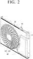
- FIG. 2 is a perspective view of a fan guard assembly according to an exemplary embodiment of the present disclosure viewed from a front and
- FIG. 3 is a perspective view of the fan guard assembly according to the exemplary embodiment of the present disclosure viewed from a rear.
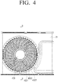
- FIG. 4 is a front view of the fan guard assembly according to the exemplary embodiment of the present disclosure and
- FIG. 5 is a rear view of the fan guard assembly according to the exemplary embodiment of the present disclosure.
- the fan guard assembly includes a front panel 31 of the cabinet and the fan guard 40 connected to the front panel 31.
- the front panel 31 may be provided with an outlet 33 for discharging air to the outside.
- the fan guard 40 may include a hub 401 provided at the outlet 33 to directly fix the fan motor assembly and a rib 402 connecting between the hub 401 and the front panel 31.
- the front panel 31 and the rib 402 may be integrally formed by injection molding.
- the fan motor assembly may include a motor 60 and a blower fan 50 driven by the motor 60.
- the blower fan 50 includes a body 501 connected to a driving shaft 601 of the motor 60 and rotating together with the motor 60 and a blade 502 connected to an outer circumferential surface of the body 501.
- the blower fan 50 may be provided in various shapes and structures for blowing the air introduced into the cabinet 30 to the outlet 33.
- the rib 402 may include a first rib 4021 radially provided from the hub 401 and a second rib 4022 spaced from the hub in a circumferential direction and connected to the first rib 4021. Further, the rib 402 may further include an auxiliary rib 4023 connecting between the second rib 4022 located at the outermost side and the front panel 31.
- the first rib 4021 may be shaped to have a height increasing outwardly and the plurality of auxiliary ribs 4023 may be provided at a predetermined position so that the second rib 4022 located at the outermost side may be easily supported on the front panel 31.
- a transverse section of the first rib 4021 may have a fan shape or an airfoil, but the shape of the transverse section of the first rib 4021 is not limited thereto, and therefore the first rib 4021 may be changed to have cross sectional areas of various shapes. Meanwhile, the number of each rib 402 may be adjusted by a user so as to stably support the fan motor assembly.
- the rib 402 will be described in detail with reference to the subsequent drawings.
- the fan guard assembly may further include a bell mouth 70 connected to the rear of the front panel 31.
- the bell mouth 70 may be screwed to the front panel 31 and thus detached from the front panel 31.
- the bell mouth 70 is located on the outer circumference of the blower fan 50 to guide the air discharged from the blower fan 50 to the outside.
- the rear of the bell mouth 70 may be referred to as an inlet through which the air discharged from the blower fan 50 is introduced into the bell mouth 70 and the front of the bell mouth 70 adjacent to the rib 402 may be referred to as an outlet through which the introduced air flows toward the rib 402 to be discharged to the outside.
- the air passing through the blower fan 50 may be smoothly introduced by preventing an eddy current at the inlet of the bell mouth 70 to improve flow noise.
- the bell mouth 70 may be provided in various curvatures or shapes so as to form a flow channel through which air flows.
- FIG. 6 is a cross-sectional view taken along direction A-A of FIG. 4 and FIG. 7 is an exploded perspective view of the fan guard assembly according to the exemplary embodiment of the present disclosure.
- the operation of the outdoor unit will be described with reference to FIGS. 6 and 7 , focusing on differences from the existing outdoor unit.
- an insertion groove 4010 having a predetermined depth is provided on a rear surface of the hub 401 to insert the motor 60 into the insertion groove 4010 and fix the motor 60 thereto.
- the hub 401 may have a fastening portion 4015 protruding from the outer circumferential surface, and the motor 60 may be screwed to a fastening hole (not illustrated) formed in the fastening portion 4015. That is, the motor 60 may be firmly fixed to the fastening portion 4015 in a state where the motor 60 is inserted into the insertion groove 4010 at a predetermined depth to be stably supported.
- the rib 401 is connected to the hub 401 and the front panel 31, respectively, and thus the hub 401 located at the outlet 33 is stably supported on the front panel 31.
- the rib 402 may have enough rigidity to withstand a weight of the motor 60 and the blower fan 50.
- the compressor if the compressor is driven, the refrigerant is compressed under a high temperature and a high pressure while passing through the compressor and is transferred to a heat exchanger serving as the condenser.
- the blower fan 50 rotates by driving the motor 60, and outdoor air is introduced into the cabinet 30 through the inlet formed on the side surface or the rear surface of the cabinet 30.
- the air introduced into the cabinet 30 is compressed under a high temperature and a high pressure while passing through the heat exchanger to cool the refrigerant flowing into the heat exchanger.
- the air passing through the heat exchanger is transferred to the bell mouth 70 through the blower fan 50 and the blower fan 50 is located inside the bell mouth 70.
- the air inside the cabinet 30 is introduced through the bell mouth 70 and is discharged to the outside.
- a separate motor bracket is provided to fix the motor and blower fan to the outdoor unit.
- the motor bracket is provided between the condenser and the fan in the outdoor unit. In the installation structure, the air introduced into the inlet sequentially passes through the condenser, the motor bracket, and the blower fan and then is discharged through the outlet.
- the motor bracket since the motor and the motor bracket are provided at a suction side of the fan, a channel resistance of the suction side of the fan increases, and thus the fan performance may deteriorate.
- the motor bracket since the motor bracket needs to have predetermined rigidity to support the motor due to the characteristics of the motor, the motor bracket should be formed as large as possible.
- the motor bracket has a structure to increase the channel resistance, but the fan guard assembly according to the exemplary embodiment of the present disclosure directly fixes the motor 60 to the hub 401 to prevent the blower fan performance from decreasing due to the increase in the channel resistance, thereby effectively decreasing the power consumption of the motor 60 and minimizing the noise.
- FIG. 8 is an enlarged perspective view for explaining an accommodating portion illustrated in FIG. 7 .
- the accommodating portion 403 may be provided on the rear surface of at least one first rib 4021 radially located from the hub 401.
- An electric wire 65 supplying electric power is connected to the motor 60.
- the electric wire 65 connected to the motor 60 is accommodated in the accommodating portion 403.
- protruding portions 4031 may be provided on the rear surface of at least one first rib 4021 to be spaced apart from each other toward the rear.
- the protruding portion 4031 may have a predetermined height along a longitudinal direction of the first rib 4021 and the accommodating portion 403 may be formed between the respective protrusions 4031.
- the bell mouth 70 has a through hole 701 to allow the electric wire 65 to pass through.
- the protruding portion 4031 may be formed with a fixing protrusion 4032 protruding along the circumferential direction.
- the fixing protrusions 4032 may be provided to be spaced apart from the opposite protrusion 4031 by a predetermined distance. Therefore, the electric wire 65 is stably accommodated in the accommodating portion 403 without being exposed to the blower fan 50 by the fixing protrusion 4032, and may be prevented from being damaged due to the contact with the blower fan 50.
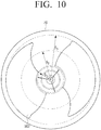
- FIGS. 9 and 10 are views for explaining a cross section structure of the fan guard assembly according to the exemplary embodiment of the present disclosure.
- the first rib 4021 may be provided to have greater rigidity outwardly so as to easily support the motor 60 and the blower fan 50.
- a tip of the first rib 4021 may be located on the same plane and a rear end of the first rib 4021 may be shaped to have a height increasing toward the blower fan 50.
- the height of the first rib 4021 may be set to have a greater height outwardly with respect to the hub 401.
- the first rib 4021 has a first end surface S 1 corresponding to a position where it is connected to the hub 40, a second end surface S 3 corresponding to a tip of a blade 502, and a third end surface S 2 located between the first end surface S 1 and the second end surface S 3 , at the same distance from the first end surface S 1 and the second end surface S 3 , respectively.
- the first end surface S 1 may have a height of 0.02 to 0.09 times the distance L from a center of the hub 401 to the tip of the blade 502.
- the second end surface S 3 may have a height of 0.04 to 0.2 times the distance L from the center of the hub 401 to the tip of the blade 502.
- the third end surface S 2 may have a height of 0.03 to 0.14 times the distance L from the center of the hub 401 to the tip of the blade 502.
- first rib 4021 may be provided so that a tilt angle of a cross section thereof increases as being far away from the hub 401 with respect to a driving shaft 601 of the motor 60.
- the first end surface S 1 may have a tilt angle A 1 of 10° to 30° and the second end surface S 3 may have a tilt angle A 3 of 20° to 40°.
- the third end surface S 2 may have a tilt angle A 2 of 15° to 35°.
- the rigidity for stably supporting the motor 60 and the blower fan 50 may be ensured by providing the height (and number) and the tilt angle of the first rib 4021. Further, it is possible to satisfy the standards on a safety distance h 1 (finger safety) between the rib 402 and the blower fan 50 while preventing potential safety accidents that may occur due to the contact of a part (e.g., a finger, etc.) of a user's body with the blower fan 50.
- h 1 finger safety
- the fan guard assembly according to the exemplary embodiment of the present disclosure is mounted to directly support the motor 60 to the insertion groove 4010 of the hub 401 to remove the additional working processes, thereby increasing the assembling productivity.
- the tilt angle of the first rib 4021 may be optimized to effectively decrease the noise increasing in proportion to an air volume in the outdoor unit 20 of the air conditioner.
- the flow resistance of the air discharged to the outlet may decrease, and as a result noise and power consumption may decrease.
- the performance of the blower fan 50 may be improved and as a result the miniaturization of the motor 60 may be achieved.
Landscapes
- Engineering & Computer Science (AREA)
- Mechanical Engineering (AREA)
- General Engineering & Computer Science (AREA)
- Chemical & Material Sciences (AREA)
- Combustion & Propulsion (AREA)
- Structures Of Non-Positive Displacement Pumps (AREA)
- Other Air-Conditioning Systems (AREA)
Abstract
Description
- The present invention relates to a fan guard assembly having an improved structure for providing improved performance and an outdoor unit having the same.
- In general, an air conditioner is a device removing dust, and the like in the air while controlling a distribution of temperature, humidity, an air current, and the like, appropriate for human activities using a freezing cycle. Main components configuring the freezing cycle include a compressor, a condenser, an evaporator, a blower fan, and the like.
- An air conditioner is referred to as a split type air conditioner when an indoor unit and an outdoor unit are installed separately and is referred to as an integrated air conditioner when the indoor unit and the outdoor unit are installed together in a single cabinet. The split type air conditioner is composed of the indoor unit having the evaporator and the fan and the outdoor unit having the compressor, the condenser, and the fan.
- The outdoor unit of the split type air conditioner has a motor for rotating the fan and a motor bracket for supporting the motor. Considering a position where the motor and the motor bracket are installed in the outdoor unit, it is common that the motor and the motor bracket are installed between the condenser and the fan. Describing the flow of air in the installation structure, air introduced into an inlet sequentially passes through the condenser, the motor bracket, and the fan, and then is discharged through an outlet.
- However, in a structure in which the motor and the motor bracket are provided at a suction side of the fan, a channel resistance of the suction side of the fan increases, and thus the fan performance may deteriorate. In addition, since the rigidity of the motor bracket needs to be secured due to characteristics of the motor bracket, the motor bracket should be formed as large as possible. As a result, the motor bracket cannot but increase the channel resistance. As such, the decrease in the fan performance due to the increase in the channel resistance is a direct cause of an increase in power consumption of the motor and an increase in noise.
- Exemplary embodiments of the present invention overcome the above disadvantages and other disadvantages not described above. Also, the present invention is not required to overcome the disadvantages described above, and an exemplary embodiment of the present invention may not overcome any of the problems described above.
- The present disclosure provides an outdoor unit capable of decreasing a flow resistance of air flowing from a blower fan.
- The present disclosure also provides a fan guard assembly capable of securing rigidity for stably supporting a blower fan and a motor.
- According to as aspect of the present disclosure, an outdoor unit includes: a cabinet; a bell mouth provided in the cabinet; a fan guard provided at an outlet of the bell mouth; and a fan motor assembly fixed to the fan guard.
- The fan guard may include: a hub located at a center of the outlet and having the fan motor assembly fixed thereto; and a rib connecting between the hub and the cabinet.
- The fan motor assembly may include: a motor fixed to the hub; and a blower fan driven by the motor.
- A height of the rib may increase outwardly from the hub.
- The rib may include a first end surface corresponding to a position where it is connected to the hub and a second end surface corresponding to a tip of a blade of the blower fan, the first end surface may have a height of 0.02 to 0.09 times a distance L from a center of the hub to the tip of the blade, and the second end surface may have a height of 0.04 to 0.2 times the distance L.
- The rib further may include a third end surface located between the first and second end surfaces, at the same distance from the first and second end surfaces, respectively, and the third end surface may have a height of 0.03 to 0.14 times the distance L.
- A cross section of the rib may have a tilt angle increasing as being far away from the hub with respect to a driving shaft of the motor.
The rib may include a first end surface corresponding to a position where it is connected to the hub and a second end surface corresponding to a tip of a blade of the blower fan, the first end surface may have a tilt angle of 10° to 30°, and the second end surface may have a tilt angle of 20° to 40°. - The rib may further include a third end surface located between the first and second end surfaces, at the same distance from the first and second end surfaces, respectively, and the third end surface may have a tilt angle of 15° to 35°.
- The rib may include: a plurality of first ribs radially provided from the hub; and a plurality of second ribs spaced from the hub in a circumferential direction to be connected to the first ribs.
- The plurality of first ribs may include: a first rib having a height increasing outwardly from the hub; and an auxiliary rib connecting between the second rib and the cabinet.
- A tip of the first rib may be located on the same plane and a rear end of the first rib may have a height increasing toward the fan motor assembly.
- A transverse section of the first rib may have a fan shape or an airfoil.
- The hub may have an insertion portion into which at least a part of the motor is inserted.
- The hub may have a fastening portion protruding from an outer circumferential surface of the hub, and the fastening portion may have a fastening hole fastened to the motor.
- The rib may have an accommodating portion accommodating an electric wire connected to the motor.
- The bell mouth may have a through hole through which the electric wire penetrates.
- According to another aspect of the present disclosure, a fan guard assembly includes: a front panel having an outlet; and a fan guard including a hub provided at the outlet to directly fix a fan motor assembly and a rib connecting between the hub and the front panel.
- The fan guard may have greater rigidity outwardly from the hub to support the fan motor assembly.
- The front panel and the fan guard may be integrally formed.
- The above and/or other aspects of the present invention will be more apparent by describing certain exemplary embodiments of the present invention with reference to the accompanying drawings, in which:
-
FIG. 1 is a perspective view schematically illustrating an air conditioner according to an exemplary embodiment of the present disclosure; -
FIG. 2 is a perspective view of a fan guard assembly according to an exemplary embodiment of the present disclosure viewed from a front; -
FIG. 3 is a perspective view of the fan guard assembly according to the exemplary embodiment of the present disclosure viewed from a rear; -
FIG. 4 is a front view of the fan guard assembly according to the exemplary embodiment of the present disclosure; -
FIG. 5 is a rear view of the fan guard assembly according to the exemplary embodiment of the present disclosure; -
FIG. 6 is a cross-sectional view taken along direction A-A ofFIG. 4 ; -
FIG. 7 is an exploded perspective view of the fan guard assembly according to the exemplary embodiment of the present disclosure; -
FIG. 8 is an enlarged perspective view for explaining an accommodating portion illustrated inFIG. 7 ; and -
FIGS. 9 and10 are views for explaining a cross section structure of the fan guard assembly according to the exemplary embodiment of the present disclosure. - Hereinafter, exemplary embodiments of the present disclosure will be described in more detail with reference to
FIGS. 1 to 10 .
To help understand the following exemplary embodiments, in signs described in the accompanying drawing, relevant components among components performing the same operations in each exemplary embodiment are denoted by reference numerals on the same or extending line. -
FIG. 1 is a perspective view schematically illustrating an air conditioner according to an exemplary embodiment of the present disclosure. Referring toFIG. 1 , an air conditioner according to an exemplary embodiment of the present disclosure includes anindoor unit 10 and anoutdoor unit 20. Theindoor unit 10 and theoutdoor unit 20 may be connected to each other by arefrigerant pipe 13. - The
refrigerant pipe 13 may include afirst refrigerant pipe 13a and asecond refrigerant pipe 13b. A refrigerant condensed in theoutdoor unit 20 may move to theindoor unit 10 through afirst refrigerant pipe 13a. The refrigerant exchanging heat with indoor air in theindoor unit 10 may move to theoutdoor unit 20 through thesecond refrigerant pipe 13b. The refrigerant may circulate through a refrigerant pipe (not illustrated) installed in theindoor unit 10 and a refrigerant pipe (not illustrated) installed in theoutdoor unit 20 through therefrigerant pipe 13. - The
indoor unit 10 may discharge the air, which is heat exchanged with the refrigerant compressed and condensed in theoutdoor unit 20, to the interior of a room to maintain the room temperature at an appropriate temperature. Theindoor unit 10 may include an expansion valve and an evaporator. The air cooled by the refrigerant evaporated in the evaporator is discharged to the interior of a room, and thus the room air may be cooled. Theindoor unit 10 may be provided with a fan assembly (not illustrated) and a diffuser assembly (not illustrated) so that the air cooled by the refrigerant may be smoothly discharged into the interior of a room. - The outdoor unit may include a
cabinet 30 forming an appearance and a fan guard provided at an outlet of thecabinet 30. The inside of thecabinet 30 may be provided with a compressor, a condenser, and a blower fan. Thecabinet 30 may be provided with an inlet through which external air is introduced and an outlet through which the introduced air may be discharged to the outside. The outlet may be provided with thefan guard 40 for protecting the blower fan. The compressor compresses the refrigerant, and the compressed refrigerant is introduced into the condenser to be condensed. At this time, the blower fan is driven and the external air introduced through the inlet may cool heat generated in the condenser. A construction and an operation of the outdoor unit and the indoor unit are well known in the art and thus a detailed description thereof will be omitted. -
FIG. 2 is a perspective view of a fan guard assembly according to an exemplary embodiment of the present disclosure viewed from a front andFIG. 3 is a perspective view of the fan guard assembly according to the exemplary embodiment of the present disclosure viewed from a rear.FIG. 4 is a front view of the fan guard assembly according to the exemplary embodiment of the present disclosure andFIG. 5 is a rear view of the fan guard assembly according to the exemplary embodiment of the present disclosure. - Referring to
FIGS. 2 to 5 , the fan guard assembly includes afront panel 31 of the cabinet and thefan guard 40 connected to thefront panel 31. Thefront panel 31 may be provided with anoutlet 33 for discharging air to the outside. Thefan guard 40 may include ahub 401 provided at theoutlet 33 to directly fix the fan motor assembly and arib 402 connecting between thehub 401 and thefront panel 31. Thefront panel 31 and therib 402 may be integrally formed by injection molding. - Here, the fan motor assembly may include a
motor 60 and ablower fan 50 driven by themotor 60. Further, theblower fan 50 includes abody 501 connected to a drivingshaft 601 of themotor 60 and rotating together with themotor 60 and ablade 502 connected to an outer circumferential surface of thebody 501. Here, theblower fan 50 may be provided in various shapes and structures for blowing the air introduced into thecabinet 30 to theoutlet 33. - The
rib 402 may include afirst rib 4021 radially provided from thehub 401 and asecond rib 4022 spaced from the hub in a circumferential direction and connected to thefirst rib 4021. Further, therib 402 may further include anauxiliary rib 4023 connecting between thesecond rib 4022 located at the outermost side and thefront panel 31. Thefirst rib 4021 may be shaped to have a height increasing outwardly and the plurality ofauxiliary ribs 4023 may be provided at a predetermined position so that thesecond rib 4022 located at the outermost side may be easily supported on thefront panel 31. - For example, a transverse section of the
first rib 4021 may have a fan shape or an airfoil, but the shape of the transverse section of thefirst rib 4021 is not limited thereto, and therefore thefirst rib 4021 may be changed to have cross sectional areas of various shapes. Meanwhile, the number of eachrib 402 may be adjusted by a user so as to stably support the fan motor assembly. Therib 402 will be described in detail with reference to the subsequent drawings. - In addition, the fan guard assembly may further include a
bell mouth 70 connected to the rear of thefront panel 31. For example, thebell mouth 70 may be screwed to thefront panel 31 and thus detached from thefront panel 31. Thebell mouth 70 is located on the outer circumference of theblower fan 50 to guide the air discharged from theblower fan 50 to the outside. - For example, the rear of the
bell mouth 70 may be referred to as an inlet through which the air discharged from theblower fan 50 is introduced into thebell mouth 70 and the front of thebell mouth 70 adjacent to therib 402 may be referred to as an outlet through which the introduced air flows toward therib 402 to be discharged to the outside. The air passing through theblower fan 50 may be smoothly introduced by preventing an eddy current at the inlet of thebell mouth 70 to improve flow noise. Thebell mouth 70 may be provided in various curvatures or shapes so as to form a flow channel through which air flows. -
FIG. 6 is a cross-sectional view taken along direction A-A ofFIG. 4 andFIG. 7 is an exploded perspective view of the fan guard assembly according to the exemplary embodiment of the present disclosure. The operation of the outdoor unit will be described with reference toFIGS. 6 and7 , focusing on differences from the existing outdoor unit. - Referring to
FIGS. 6 and7 , aninsertion groove 4010 having a predetermined depth is provided on a rear surface of thehub 401 to insert themotor 60 into theinsertion groove 4010 and fix themotor 60 thereto. For example, thehub 401 may have afastening portion 4015 protruding from the outer circumferential surface, and themotor 60 may be screwed to a fastening hole (not illustrated) formed in thefastening portion 4015. That is, themotor 60 may be firmly fixed to thefastening portion 4015 in a state where themotor 60 is inserted into theinsertion groove 4010 at a predetermined depth to be stably supported. - At least a part of the
motor 60 is inserted into theinsertion groove 4010 of thehub 401. Therib 401 is connected to thehub 401 and thefront panel 31, respectively, and thus thehub 401 located at theoutlet 33 is stably supported on thefront panel 31. In particular, therib 402 may have enough rigidity to withstand a weight of themotor 60 and theblower fan 50. - For example, in the operation process of the air conditioner, if the compressor is driven, the refrigerant is compressed under a high temperature and a high pressure while passing through the compressor and is transferred to a heat exchanger serving as the condenser. At the same time, the
blower fan 50 rotates by driving themotor 60, and outdoor air is introduced into thecabinet 30 through the inlet formed on the side surface or the rear surface of thecabinet 30. - The air introduced into the
cabinet 30 is compressed under a high temperature and a high pressure while passing through the heat exchanger to cool the refrigerant flowing into the heat exchanger. - The air passing through the heat exchanger is transferred to the
bell mouth 70 through theblower fan 50 and theblower fan 50 is located inside thebell mouth 70. The air inside thecabinet 30 is introduced through thebell mouth 70 and is discharged to the outside. - Conventionally, a separate motor bracket is provided to fix the motor and blower fan to the outdoor unit. The motor bracket is provided between the condenser and the fan in the outdoor unit. In the installation structure, the air introduced into the inlet sequentially passes through the condenser, the motor bracket, and the blower fan and then is discharged through the outlet.
- That is, since the motor and the motor bracket are provided at a suction side of the fan, a channel resistance of the suction side of the fan increases, and thus the fan performance may deteriorate. In addition, since the motor bracket needs to have predetermined rigidity to support the motor due to the characteristics of the motor, the motor bracket should be formed as large as possible.
- As a result, the motor bracket has a structure to increase the channel resistance, but the fan guard assembly according to the exemplary embodiment of the present disclosure directly fixes the
motor 60 to thehub 401 to prevent the blower fan performance from decreasing due to the increase in the channel resistance, thereby effectively decreasing the power consumption of themotor 60 and minimizing the noise. -
FIG. 8 is an enlarged perspective view for explaining an accommodating portion illustrated inFIG. 7 . Referring toFIG. 8 , theaccommodating portion 403 may be provided on the rear surface of at least onefirst rib 4021 radially located from thehub 401. Anelectric wire 65 supplying electric power is connected to themotor 60. Here, theelectric wire 65 connected to themotor 60 is accommodated in theaccommodating portion 403. - For example, protruding
portions 4031 may be provided on the rear surface of at least onefirst rib 4021 to be spaced apart from each other toward the rear. The protrudingportion 4031 may have a predetermined height along a longitudinal direction of thefirst rib 4021 and theaccommodating portion 403 may be formed between therespective protrusions 4031. Further, thebell mouth 70 has a throughhole 701 to allow theelectric wire 65 to pass through. - Further, at least a part of the protruding
portion 4031 may be formed with a fixingprotrusion 4032 protruding along the circumferential direction. The fixingprotrusions 4032 may be provided to be spaced apart from theopposite protrusion 4031 by a predetermined distance. Therefore, theelectric wire 65 is stably accommodated in theaccommodating portion 403 without being exposed to theblower fan 50 by the fixingprotrusion 4032, and may be prevented from being damaged due to the contact with theblower fan 50. -
FIGS. 9 and10 are views for explaining a cross section structure of the fan guard assembly according to the exemplary embodiment of the present disclosure. Referring toFIGS. 9 and10 , thefirst rib 4021 may be provided to have greater rigidity outwardly so as to easily support themotor 60 and theblower fan 50. A tip of thefirst rib 4021 may be located on the same plane and a rear end of thefirst rib 4021 may be shaped to have a height increasing toward theblower fan 50. - For example, the height of the
first rib 4021 may be set to have a greater height outwardly with respect to thehub 401. Thefirst rib 4021 has a first end surface S1 corresponding to a position where it is connected to thehub 40, a second end surface S3 corresponding to a tip of ablade 502, and a third end surface S2 located between the first end surface S1 and the second end surface S3, at the same distance from the first end surface S1 and the second end surface S3, respectively. - Here, the first end surface S1 may have a height of 0.02 to 0.09 times the distance L from a center of the
hub 401 to the tip of theblade 502. The second end surface S3 may have a height of 0.04 to 0.2 times the distance L from the center of thehub 401 to the tip of theblade 502. The third end surface S2 may have a height of 0.03 to 0.14 times the distance L from the center of thehub 401 to the tip of theblade 502. - Further, the
first rib 4021 may be provided so that a tilt angle of a cross section thereof increases as being far away from thehub 401 with respect to a drivingshaft 601 of themotor 60. The first end surface S1 may have a tilt angle A1 of 10° to 30° and the second end surface S3 may have a tilt angle A3 of 20° to 40°. In addition, the third end surface S2 may have a tilt angle A2 of 15° to 35°. - In particular, the rigidity for stably supporting the
motor 60 and theblower fan 50 may be ensured by providing the height (and number) and the tilt angle of thefirst rib 4021. Further, it is possible to satisfy the standards on a safety distance h1 (finger safety) between therib 402 and theblower fan 50 while preventing potential safety accidents that may occur due to the contact of a part (e.g., a finger, etc.) of a user's body with theblower fan 50. - Conventionally, it takes much working process time to mount the
motor 60 and theblower fan 50 on the motor bracket that is a separate component, but the fan guard assembly according to the exemplary embodiment of the present disclosure is mounted to directly support themotor 60 to theinsertion groove 4010 of thehub 401 to remove the additional working processes, thereby increasing the assembling productivity. - In addition, the tilt angle of the
first rib 4021 may be optimized to effectively decrease the noise increasing in proportion to an air volume in theoutdoor unit 20 of the air conditioner. In addition, by eliminating the configuration of the motor bracket which is separately installed in the existing outdoor unit, the flow resistance of the air discharged to the outlet may decrease, and as a result noise and power consumption may decrease. Furthermore, the performance of theblower fan 50 may be improved and as a result the miniaturization of themotor 60 may be achieved. - Hereinabove, various exemplary embodiments of the present disclosure are individually described, but each exemplary embodiment need not necessarily be implemented alone and therefore the configurations and operations of each exemplary embodiment may also be implemented in combination with at least one other exemplary embodiment.
- Although the preferred exemplary embodiments of the present invention have been disclosed for illustrative purposes, those skilled in the art will appreciate that various modifications, additions and substitutions are possible, without departing from the scope of the invention as disclosed in the accompanying claims.
Claims (15)
- An outdoor unit, comprising: a cabinet;
a bell mouth provided in the cabinet;
a fan guard provided at an outlet of the bell mouth; and
a fan motor assembly fixed to the fan guard. - The outdoor unit as claimed in claim 1, wherein the fan guard includes:a hub located at a center of the outlet and having the fan motor assembly fixed thereto; anda rib connecting the hub and the cabinet.
- The outdoor unit as claimed in claim 1 or 2, wherein the fan motor assembly includes:a motor fixed to the hub; anda blower fan driven by the motor.
- The outdoor unit as claimed in claim 3, wherein a height of the rib increases outwardly from the hub.
- The outdoor unit as claimed in claim 4, wherein the rib includes
a first surface corresponding to a position where it is connected to the hub, and
a second surface corresponding to a tip of a blade of the blower fan,
wherein the first surface has a height of 0.02 to 0.09 times a distance L from a center of the hub to the tip of the blade, and
the second surface has a height of 0.04 to 0.2 times the distance L. - The outdoor unit as claimed in claim 5, wherein
the rib further includes a third surface located between the first surface and the second surface, at a same distance from the first surface and the second surface, respectively, and
the third surface has a height of 0.03 to 0.14 times the distance L. - The outdoor unit as claimed in any one of claims 3 to 6, wherein a cross section of the rib has an increasing tilt angle as the rib extends from the hub with respect to a driving shaft of the motor.
- The outdoor unit as claimed in claim 7, wherein the rib includes
a first surface corresponding to a position where it is connected to the hub, and
a second surface corresponding to a tip of a blade of the blower fan,wherein the first surface has a tilt angle of 10° to 30°, and the second surface has a tilt angle of 20° to 40°. - The outdoor unit as claimed in claim 8, wherein
the rib further includes a third surface located between the first surface and the second surface, at a same distance from the first surface and the second surface, respectively, and
the third surface has a tilt angle of 15° to 35°. - The outdoor unit as claimed in any one of claims 2 to 9, wherein the rib includes:a plurality of first ribs radially provided from the hub; anda plurality of second ribs spaced from the hub in a circumferential direction connected to the plurality of first ribs.
- The outdoor unit as claimed in claim 10, wherein the plurality of first ribs include:a first rib having a height increasing outwardly from the hub; andan auxiliary rib connecting the second rib and the cabinet.
- The outdoor unit as claimed in claim 11, wherein a tip of the first rib is located on a same plane and a rear end of the first rib has a height increasing toward the fan motor assembly.
- The outdoor unit as claimed in any one of claims 3 to 12, wherein the hub has an insertion portion into which at least a part of the motor is inserted.
- The outdoor unit as claimed in claim 13, wherein the hub has a fastening portion protruding from an outer circumferential surface of the hub, and
the fastening portion has a fastening hole to fasten the motor. - A fan guard assembly, comprising:a front panel having an outlet; anda fan guard including:a hub provided at the outlet to directly fix a fan motor assembly, anda rib connecting between the hub and the front panel.
Applications Claiming Priority (1)
| Application Number | Priority Date | Filing Date | Title |
|---|---|---|---|
| KR1020160067520A KR102489427B1 (en) | 2016-05-31 | 2016-05-31 | Fan guard assembly and outdoor unit having the same |
Publications (3)
| Publication Number | Publication Date |
|---|---|
| EP3287707A1 true EP3287707A1 (en) | 2018-02-28 |
| EP3287707C0 EP3287707C0 (en) | 2025-05-28 |
| EP3287707B1 EP3287707B1 (en) | 2025-05-28 |
Family
ID=58644970
Family Applications (1)
| Application Number | Title | Priority Date | Filing Date |
|---|---|---|---|
| EP17168834.4A Active EP3287707B1 (en) | 2016-05-31 | 2017-04-28 | Fan guard assembly and outdoor unit having the same |
Country Status (3)
| Country | Link |
|---|---|
| US (1) | US10871172B2 (en) |
| EP (1) | EP3287707B1 (en) |
| KR (1) | KR102489427B1 (en) |
Cited By (2)
| Publication number | Priority date | Publication date | Assignee | Title |
|---|---|---|---|---|
| EP3677846A1 (en) | 2019-01-04 | 2020-07-08 | Vaillant GmbH | Outdoor unit of an air conditioner |
| EP3880967A1 (en) * | 2018-11-16 | 2021-09-22 | ebm-papst Mulfingen GmbH & Co. KG | Diagonal fan with outlet guide vane device |
Families Citing this family (16)
| Publication number | Priority date | Publication date | Assignee | Title |
|---|---|---|---|---|
| CN106766055B (en) * | 2017-02-17 | 2019-08-13 | 珠海格力电器股份有限公司 | Air guide grid, air inlet panel and air conditioner |
| CN207122442U (en) * | 2017-08-18 | 2018-03-20 | 开利公司 | Fan casing and there is its air-conditioner set |
| USD894366S1 (en) * | 2018-05-07 | 2020-08-25 | Ebm-Papst Mulfingen Gmbh & Co. Kg | Ventilation unit |
| USD890328S1 (en) * | 2018-05-07 | 2020-07-14 | Ebm-Papst Mulfingen Gmbh & Co. Kg | Ventilation grid |
| DE102018128792A1 (en) * | 2018-11-16 | 2020-05-20 | Ebm-Papst Mulfingen Gmbh & Co. Kg | Compact diagonal fan with guide device |
| WO2020132722A1 (en) | 2018-12-28 | 2020-07-02 | Springer Carrier Ltda. | Grille for ventilation apparatus |
| WO2020156237A1 (en) * | 2019-02-03 | 2020-08-06 | 广东美的制冷设备有限公司 | Rear encircling plate assembly of window type air conditioner, window type air conditioner and window type air conditioner device |
| CN112576529A (en) * | 2019-09-27 | 2021-03-30 | 广东美的环境电器制造有限公司 | Fan with cooling device |
| USD938573S1 (en) * | 2019-11-27 | 2021-12-14 | Jiangmen Keye Electric Appliances Manufacturing Co. Ltd | Fan grille |
| CN111351086B (en) * | 2020-04-22 | 2024-07-23 | 佛山市顺德区美的洗涤电器制造有限公司 | Steam generator mounting assembly and range hood |
| US20220325905A1 (en) * | 2021-04-07 | 2022-10-13 | Rheem Manufacturing Company | Air handling unit and fan therefor |
| KR20230121322A (en) | 2022-02-11 | 2023-08-18 | 엘지전자 주식회사 | Outdoor unit for air conditioner |
| KR20230121325A (en) | 2022-02-11 | 2023-08-18 | 엘지전자 주식회사 | Outdoor unit for air conditioner |
| KR20230121323A (en) | 2022-02-11 | 2023-08-18 | 엘지전자 주식회사 | Outdoor unit for air conditioner |
| KR20230124788A (en) | 2022-02-18 | 2023-08-28 | 엘지전자 주식회사 | Outdoor unit for air conditioner |
| WO2025264103A1 (en) * | 2024-06-18 | 2025-12-26 | Daikin Research & Development Malaysia Sdn. Bhd. | An outdoor unit for an air conditioner |
Citations (6)
| Publication number | Priority date | Publication date | Assignee | Title |
|---|---|---|---|---|
| JPH0396700A (en) * | 1989-09-08 | 1991-04-22 | Toshiba Corp | Air blower |
| US5097678A (en) * | 1990-11-19 | 1992-03-24 | Aubuchon Steven L | Ventilating protective cover for top-discharge air conditioners |
| US20040146395A1 (en) * | 2003-01-27 | 2004-07-29 | Lennox Industries, Inc. | Noise reduction by vortex suppression in air flow systems |
| US20090110542A1 (en) * | 2007-10-30 | 2009-04-30 | Samsung Electronics Co., Ltd. | Fan guard and outdoor unit for air conditioner having the same |
| KR20090130670A (en) * | 2008-06-16 | 2009-12-24 | 삼성전자주식회사 | Outdoor unit of air conditioner |
| US20140154095A1 (en) * | 2012-11-30 | 2014-06-05 | Plasticos y Alambres, S.A. DE C.V. | Fan guard for air conditioning machine |
Family Cites Families (13)
| Publication number | Priority date | Publication date | Assignee | Title |
|---|---|---|---|---|
| US5117656A (en) * | 1990-04-23 | 1992-06-02 | General Electric Company | Outdoor unit for a central system for conditioning air, assembly for use with a housing of such unit, and method of assembling a blower motor to a cover for such unit |
| US6139265A (en) * | 1996-05-01 | 2000-10-31 | Valeo Thermique Moteur | Stator fan |
| KR100275313B1 (en) * | 1997-11-04 | 2001-01-15 | 홍은수 | fan |
| KR100408781B1 (en) * | 1999-08-09 | 2003-12-06 | 다이킨 고교 가부시키가이샤 | Fan guard of blowing unit and air conditioning apparatus |
| JP3982181B2 (en) * | 2001-01-29 | 2007-09-26 | ダイキン工業株式会社 | Fan guard for blower unit |
| JP2004156884A (en) * | 2002-11-08 | 2004-06-03 | Daikin Ind Ltd | Fan guard for blower unit |
| US7011504B2 (en) * | 2003-04-04 | 2006-03-14 | Nidec America Corporation | Fan, fan guard and related method |
| US7811055B2 (en) | 2004-04-26 | 2010-10-12 | Behr Gmbh & Co. Kg | Fan housing for a heat exchanger, particular for motor vehicles |
| KR200466110Y1 (en) | 2007-07-30 | 2013-04-03 | 삼성전자주식회사 | Outdoor unit of air conditioner |
| KR101583080B1 (en) * | 2009-03-12 | 2016-01-07 | 엘지전자 주식회사 | Outdoor unit for air conditioner |
| JP5824656B2 (en) * | 2011-08-23 | 2015-11-25 | パナソニックIpマネジメント株式会社 | Air conditioner outdoor unit |
| JP2013119816A (en) | 2011-12-08 | 2013-06-17 | Samsung Yokohama Research Institute Co Ltd | Propeller fan and outdoor unit of air conditioning apparatus |
| KR20140014409A (en) * | 2012-06-22 | 2014-02-06 | 삼성전자주식회사 | Indoor unit of air conditioner |
-
2016
- 2016-05-31 KR KR1020160067520A patent/KR102489427B1/en active Active
-
2017
- 2017-04-07 US US15/482,011 patent/US10871172B2/en active Active
- 2017-04-28 EP EP17168834.4A patent/EP3287707B1/en active Active
Patent Citations (6)
| Publication number | Priority date | Publication date | Assignee | Title |
|---|---|---|---|---|
| JPH0396700A (en) * | 1989-09-08 | 1991-04-22 | Toshiba Corp | Air blower |
| US5097678A (en) * | 1990-11-19 | 1992-03-24 | Aubuchon Steven L | Ventilating protective cover for top-discharge air conditioners |
| US20040146395A1 (en) * | 2003-01-27 | 2004-07-29 | Lennox Industries, Inc. | Noise reduction by vortex suppression in air flow systems |
| US20090110542A1 (en) * | 2007-10-30 | 2009-04-30 | Samsung Electronics Co., Ltd. | Fan guard and outdoor unit for air conditioner having the same |
| KR20090130670A (en) * | 2008-06-16 | 2009-12-24 | 삼성전자주식회사 | Outdoor unit of air conditioner |
| US20140154095A1 (en) * | 2012-11-30 | 2014-06-05 | Plasticos y Alambres, S.A. DE C.V. | Fan guard for air conditioning machine |
Cited By (5)
| Publication number | Priority date | Publication date | Assignee | Title |
|---|---|---|---|---|
| EP3880967A1 (en) * | 2018-11-16 | 2021-09-22 | ebm-papst Mulfingen GmbH & Co. KG | Diagonal fan with outlet guide vane device |
| US12006947B2 (en) | 2018-11-16 | 2024-06-11 | Ebm-Papst Mulfingen Gmbh & Co. Kg | Diagonal fan with outlet guide vane device |
| EP3880967B1 (en) * | 2018-11-16 | 2025-12-03 | ebm-papst Mulfingen GmbH & Co. KG | Diagonal fan with outlet guide vane device |
| EP3677846A1 (en) | 2019-01-04 | 2020-07-08 | Vaillant GmbH | Outdoor unit of an air conditioner |
| DE102019100109A1 (en) | 2019-01-04 | 2020-07-09 | Vaillant Gmbh | Increased efficiency for heat pump ventilation |
Also Published As
| Publication number | Publication date |
|---|---|
| US20170343016A1 (en) | 2017-11-30 |
| EP3287707C0 (en) | 2025-05-28 |
| KR20170135503A (en) | 2017-12-08 |
| EP3287707B1 (en) | 2025-05-28 |
| US10871172B2 (en) | 2020-12-22 |
| KR102489427B1 (en) | 2023-01-18 |
Similar Documents
| Publication | Publication Date | Title |
|---|---|---|
| EP3287707B1 (en) | Fan guard assembly and outdoor unit having the same | |
| CN101608815B (en) | Outdoor machine of air conditioner | |
| US10465697B2 (en) | Centrifugal fan and air conditioner having the same | |
| CN101802526B (en) | Partition and condenser shroud for an air conditioning unit | |
| EP2781844B1 (en) | Turbo fan and ceiling type air conditioner using the same | |
| EP3040629B1 (en) | Outdoor device for an air conditioner | |
| KR20190004118A (en) | Window type air conditioner | |
| EP3631307B1 (en) | Air conditioner | |
| KR20190010240A (en) | Control box and Window type air conditioner including the same | |
| KR20170020146A (en) | Indoor unit for air conditoiner | |
| KR20180106587A (en) | Air conditioner | |
| KR20190139054A (en) | An outdoor unit for a an air conditioner | |
| EP4273459B1 (en) | Air conditioner | |
| JP7370477B2 (en) | Air conditioner outdoor unit | |
| US20070044496A1 (en) | Monolithic air conditioner | |
| KR20130109515A (en) | Axial fan of outdoor unit of air conditioner | |
| KR20090076031A (en) | Blower and outdoor unit of air conditioner having same | |
| KR20200114497A (en) | Window type air conditioner | |
| KR101229343B1 (en) | Ceiling Type Air Conditioner | |
| JP2008196841A (en) | Air conditioner | |
| US20060254304A1 (en) | Indoor unit of an air conditioner | |
| KR100437393B1 (en) | Control box mounting apparatus for air conditioner | |
| KR100676251B1 (en) | Outdoor unit of air conditioner | |
| EP3161395B1 (en) | Plug-type holder with improved assemblage for securing a fan assembly in a refrigerator | |
| KR100677517B1 (en) | Air conditioner |
Legal Events
| Date | Code | Title | Description |
|---|---|---|---|
| PUAI | Public reference made under article 153(3) epc to a published international application that has entered the european phase |
Free format text: ORIGINAL CODE: 0009012 |
|
| STAA | Information on the status of an ep patent application or granted ep patent |
Free format text: STATUS: REQUEST FOR EXAMINATION WAS MADE |
|
| 17P | Request for examination filed |
Effective date: 20170428 |
|
| AK | Designated contracting states |
Kind code of ref document: A1 Designated state(s): AL AT BE BG CH CY CZ DE DK EE ES FI FR GB GR HR HU IE IS IT LI LT LU LV MC MK MT NL NO PL PT RO RS SE SI SK SM TR |
|
| AX | Request for extension of the european patent |
Extension state: BA ME |
|
| STAA | Information on the status of an ep patent application or granted ep patent |
Free format text: STATUS: EXAMINATION IS IN PROGRESS |
|
| 17Q | First examination report despatched |
Effective date: 20200416 |
|
| GRAP | Despatch of communication of intention to grant a patent |
Free format text: ORIGINAL CODE: EPIDOSNIGR1 |
|
| STAA | Information on the status of an ep patent application or granted ep patent |
Free format text: STATUS: GRANT OF PATENT IS INTENDED |
|
| INTG | Intention to grant announced |
Effective date: 20241205 |
|
| GRAS | Grant fee paid |
Free format text: ORIGINAL CODE: EPIDOSNIGR3 |
|
| GRAA | (expected) grant |
Free format text: ORIGINAL CODE: 0009210 |
|
| STAA | Information on the status of an ep patent application or granted ep patent |
Free format text: STATUS: THE PATENT HAS BEEN GRANTED |
|
| AK | Designated contracting states |
Kind code of ref document: B1 Designated state(s): AL AT BE BG CH CY CZ DE DK EE ES FI FR GB GR HR HU IE IS IT LI LT LU LV MC MK MT NL NO PL PT RO RS SE SI SK SM TR |
|
| REG | Reference to a national code |
Ref country code: GB Ref legal event code: FG4D |
|
| REG | Reference to a national code |
Ref country code: CH Ref legal event code: EP |
|
| REG | Reference to a national code |
Ref country code: IE Ref legal event code: FG4D Ref country code: DE Ref legal event code: R096 Ref document number: 602017089650 Country of ref document: DE |
|
| U01 | Request for unitary effect filed |
Effective date: 20250528 |
|
| U07 | Unitary effect registered |
Designated state(s): AT BE BG DE DK EE FI FR IT LT LU LV MT NL PT RO SE SI Effective date: 20250606 |
|
| PG25 | Lapsed in a contracting state [announced via postgrant information from national office to epo] |
Ref country code: ES Free format text: LAPSE BECAUSE OF FAILURE TO SUBMIT A TRANSLATION OF THE DESCRIPTION OR TO PAY THE FEE WITHIN THE PRESCRIBED TIME-LIMIT Effective date: 20250528 |
|
| PG25 | Lapsed in a contracting state [announced via postgrant information from national office to epo] |
Ref country code: GR Free format text: LAPSE BECAUSE OF FAILURE TO SUBMIT A TRANSLATION OF THE DESCRIPTION OR TO PAY THE FEE WITHIN THE PRESCRIBED TIME-LIMIT Effective date: 20250829 Ref country code: NO Free format text: LAPSE BECAUSE OF FAILURE TO SUBMIT A TRANSLATION OF THE DESCRIPTION OR TO PAY THE FEE WITHIN THE PRESCRIBED TIME-LIMIT Effective date: 20250828 |
|
| PG25 | Lapsed in a contracting state [announced via postgrant information from national office to epo] |
Ref country code: PL Free format text: LAPSE BECAUSE OF FAILURE TO SUBMIT A TRANSLATION OF THE DESCRIPTION OR TO PAY THE FEE WITHIN THE PRESCRIBED TIME-LIMIT Effective date: 20250528 |
|
| PG25 | Lapsed in a contracting state [announced via postgrant information from national office to epo] |
Ref country code: HR Free format text: LAPSE BECAUSE OF FAILURE TO SUBMIT A TRANSLATION OF THE DESCRIPTION OR TO PAY THE FEE WITHIN THE PRESCRIBED TIME-LIMIT Effective date: 20250528 |
|
| PG25 | Lapsed in a contracting state [announced via postgrant information from national office to epo] |
Ref country code: RS Free format text: LAPSE BECAUSE OF FAILURE TO SUBMIT A TRANSLATION OF THE DESCRIPTION OR TO PAY THE FEE WITHIN THE PRESCRIBED TIME-LIMIT Effective date: 20250828 |
|
| PG25 | Lapsed in a contracting state [announced via postgrant information from national office to epo] |
Ref country code: IS Free format text: LAPSE BECAUSE OF FAILURE TO SUBMIT A TRANSLATION OF THE DESCRIPTION OR TO PAY THE FEE WITHIN THE PRESCRIBED TIME-LIMIT Effective date: 20250928 |
|
| PG25 | Lapsed in a contracting state [announced via postgrant information from national office to epo] |
Ref country code: SM Free format text: LAPSE BECAUSE OF FAILURE TO SUBMIT A TRANSLATION OF THE DESCRIPTION OR TO PAY THE FEE WITHIN THE PRESCRIBED TIME-LIMIT Effective date: 20250528 |
|
| PG25 | Lapsed in a contracting state [announced via postgrant information from national office to epo] |
Ref country code: CZ Free format text: LAPSE BECAUSE OF FAILURE TO SUBMIT A TRANSLATION OF THE DESCRIPTION OR TO PAY THE FEE WITHIN THE PRESCRIBED TIME-LIMIT Effective date: 20250528 |
|
| PG25 | Lapsed in a contracting state [announced via postgrant information from national office to epo] |
Ref country code: SK Free format text: LAPSE BECAUSE OF FAILURE TO SUBMIT A TRANSLATION OF THE DESCRIPTION OR TO PAY THE FEE WITHIN THE PRESCRIBED TIME-LIMIT Effective date: 20250528 |
|
| PLBE | No opposition filed within time limit |
Free format text: ORIGINAL CODE: 0009261 |
|
| STAA | Information on the status of an ep patent application or granted ep patent |
Free format text: STATUS: NO OPPOSITION FILED WITHIN TIME LIMIT |
|
| PGFP | Annual fee paid to national office [announced via postgrant information from national office to epo] |
Ref country code: GB Payment date: 20260324 Year of fee payment: 10 |
|
| REG | Reference to a national code |
Ref country code: CH Ref legal event code: L10 Free format text: ST27 STATUS EVENT CODE: U-0-0-L10-L00 (AS PROVIDED BY THE NATIONAL OFFICE) Effective date: 20260409 |