EP3287658A1 - Piston for disc brake device - Google Patents
Piston for disc brake device Download PDFInfo
- Publication number
- EP3287658A1 EP3287658A1 EP16783166.8A EP16783166A EP3287658A1 EP 3287658 A1 EP3287658 A1 EP 3287658A1 EP 16783166 A EP16783166 A EP 16783166A EP 3287658 A1 EP3287658 A1 EP 3287658A1
- Authority
- EP
- European Patent Office
- Prior art keywords
- piston
- wall portion
- reinforcement
- disc brake
- brake device
- Prior art date
- Legal status (The legal status is an assumption and is not a legal conclusion. Google has not performed a legal analysis and makes no representation as to the accuracy of the status listed.)
- Withdrawn
Links
- 230000002787 reinforcement Effects 0.000 claims abstract description 211
- 239000012530 fluid Substances 0.000 claims description 13
- 230000002093 peripheral effect Effects 0.000 abstract 1
- 238000010276 construction Methods 0.000 description 15
- 238000000034 method Methods 0.000 description 9
- 230000001965 increasing effect Effects 0.000 description 7
- 230000003245 working effect Effects 0.000 description 6
- 239000000463 material Substances 0.000 description 5
- 238000007493 shaping process Methods 0.000 description 4
- 239000000843 powder Substances 0.000 description 3
- 230000001105 regulatory effect Effects 0.000 description 3
- 239000007787 solid Substances 0.000 description 3
- 229910000838 Al alloy Inorganic materials 0.000 description 2
- XEEYBQQBJWHFJM-UHFFFAOYSA-N Iron Chemical compound [Fe] XEEYBQQBJWHFJM-UHFFFAOYSA-N 0.000 description 2
- 238000005452 bending Methods 0.000 description 2
- 230000006835 compression Effects 0.000 description 2
- 238000007906 compression Methods 0.000 description 2
- 239000000470 constituent Substances 0.000 description 2
- 230000000994 depressogenic effect Effects 0.000 description 2
- 230000002708 enhancing effect Effects 0.000 description 2
- 229910052751 metal Inorganic materials 0.000 description 2
- 239000002184 metal Substances 0.000 description 2
- 229910045601 alloy Inorganic materials 0.000 description 1
- 239000000956 alloy Substances 0.000 description 1
- 238000000151 deposition Methods 0.000 description 1
- 230000008021 deposition Effects 0.000 description 1
- 238000010586 diagram Methods 0.000 description 1
- 229910052742 iron Inorganic materials 0.000 description 1
- 238000010030 laminating Methods 0.000 description 1
- 238000001465 metallisation Methods 0.000 description 1
- 230000003287 optical effect Effects 0.000 description 1
- 239000005011 phenolic resin Substances 0.000 description 1
- 239000011347 resin Substances 0.000 description 1
- 229920005989 resin Polymers 0.000 description 1
- 238000000110 selective laser sintering Methods 0.000 description 1
- 238000005245 sintering Methods 0.000 description 1
- 239000000725 suspension Substances 0.000 description 1
- 229920001187 thermosetting polymer Polymers 0.000 description 1
- 239000013585 weight reducing agent Substances 0.000 description 1
Images





Classifications
-
- F—MECHANICAL ENGINEERING; LIGHTING; HEATING; WEAPONS; BLASTING
- F16—ENGINEERING ELEMENTS AND UNITS; GENERAL MEASURES FOR PRODUCING AND MAINTAINING EFFECTIVE FUNCTIONING OF MACHINES OR INSTALLATIONS; THERMAL INSULATION IN GENERAL
- F16D—COUPLINGS FOR TRANSMITTING ROTATION; CLUTCHES; BRAKES
- F16D65/00—Parts or details
- F16D65/14—Actuating mechanisms for brakes; Means for initiating operation at a predetermined position
- F16D65/16—Actuating mechanisms for brakes; Means for initiating operation at a predetermined position arranged in or on the brake
- F16D65/18—Actuating mechanisms for brakes; Means for initiating operation at a predetermined position arranged in or on the brake adapted for drawing members together, e.g. for disc brakes
-
- F—MECHANICAL ENGINEERING; LIGHTING; HEATING; WEAPONS; BLASTING
- F16—ENGINEERING ELEMENTS AND UNITS; GENERAL MEASURES FOR PRODUCING AND MAINTAINING EFFECTIVE FUNCTIONING OF MACHINES OR INSTALLATIONS; THERMAL INSULATION IN GENERAL
- F16D—COUPLINGS FOR TRANSMITTING ROTATION; CLUTCHES; BRAKES
- F16D55/00—Brakes with substantially-radial braking surfaces pressed together in axial direction, e.g. disc brakes
- F16D55/02—Brakes with substantially-radial braking surfaces pressed together in axial direction, e.g. disc brakes with axially-movable discs or pads pressed against axially-located rotating members
- F16D55/22—Brakes with substantially-radial braking surfaces pressed together in axial direction, e.g. disc brakes with axially-movable discs or pads pressed against axially-located rotating members by clamping an axially-located rotating disc between movable braking members, e.g. movable brake discs or brake pads
- F16D55/228—Brakes with substantially-radial braking surfaces pressed together in axial direction, e.g. disc brakes with axially-movable discs or pads pressed against axially-located rotating members by clamping an axially-located rotating disc between movable braking members, e.g. movable brake discs or brake pads with a separate actuating member for each side
-
- F—MECHANICAL ENGINEERING; LIGHTING; HEATING; WEAPONS; BLASTING
- F16—ENGINEERING ELEMENTS AND UNITS; GENERAL MEASURES FOR PRODUCING AND MAINTAINING EFFECTIVE FUNCTIONING OF MACHINES OR INSTALLATIONS; THERMAL INSULATION IN GENERAL
- F16D—COUPLINGS FOR TRANSMITTING ROTATION; CLUTCHES; BRAKES
- F16D2121/00—Type of actuator operation force
- F16D2121/02—Fluid pressure
- F16D2121/04—Fluid pressure acting on a piston-type actuator, e.g. for liquid pressure
-
- F—MECHANICAL ENGINEERING; LIGHTING; HEATING; WEAPONS; BLASTING
- F16—ENGINEERING ELEMENTS AND UNITS; GENERAL MEASURES FOR PRODUCING AND MAINTAINING EFFECTIVE FUNCTIONING OF MACHINES OR INSTALLATIONS; THERMAL INSULATION IN GENERAL
- F16D—COUPLINGS FOR TRANSMITTING ROTATION; CLUTCHES; BRAKES
- F16D2125/00—Components of actuators
- F16D2125/02—Fluid-pressure mechanisms
- F16D2125/06—Pistons
Definitions
- the present invention relates to an improvement of a piston for a disc brake device.
- Disc brakes are widely used to slow or stop a motor vehicle.
- a pair of pads which are provided so as to hold therebetween a rotor rotating together with a wheel are caused to press against both sides of the rotor by a piston.
- a floating-type disc brake device is in use in which the pair of pads described above are supported on a support which is fixed to a suspension system so as to be displaced freely.
- the piston described above is provided only one side (an inboard side which faces a transverse center of a vehicle body with the floating-type disc brake device mounted on the motor vehicle) of the rotor.
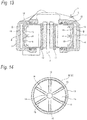
- an opposed-piston-type disc brake device described in Patent Literature 1 is shown in Figs. 13 to 14 .
- This opposed-piston-type disc brake device 1 includes a caliper 5 which is made up of an inboard body portion 3 and an outboard body portion 4 in a position where a rotor 2 is held.
- An inboard cylinder space 6 and an outboard cylinder space 7 are provided in the inboard body portion 3 and the outboard body portion 4, respectively, in such a way that their openings face each other across the rotor 2.
- an inboard piston 8 and an outboard piston 9 are fitted in the inboard piston space 6 and the outboard piston space 7, respectively, in a fluid-tight fashion and in such a way as to move in an axial direction of the rotor 2.
- an inboard pad 10 is supported in the inboard body portion 3 so as to be displaced in the axial direction of the rotor 2
- an outboard pad 11 is supported in the outboard body portion 4 so as to be displaced in the axial direction of the rotor 2.
- the inboard and outboard pistons 8, 9 are made of metal and have a bottomed cylindrical shape as a whole, including a cylindrical wall portion 12 having a cylindrical shape and a bottom wall portion 13 having a disc shape.
- the bottom wall portion 13 closes an axial end side of the cylindrical wall portion 12 which lies on a deeper side of each of the inboard and outboard cylinder spaces 6, 7.
- a substantially cylindrical projecting portion 14 is formed at a central portion of an inner surface of the bottom wall portion 13 which makes up each of the inboard and outboard pistons 8, 9. Additionally, a plurality of (six in the illustrated example) straight reinforcement ribs 15, 15 are provided circumferentially at equal intervals on the inner surface of the bottom wall portion 13 so as to extend in a radial direction (radially) to thereby continue to an outer circumferential surface of the projecting portion 14 and an inner circumferential surface of the cylindrical wall portion 12.
- the inboard and outboard pistons 8, 9 are made so rigid that when braking, the inboard and outboard pistons 8, 9 are prevented from being deformed irrespective of the fact that the pressurized fluid is introduced into the inboard and outboard cylinder spaces 6, 7.
- Patent Literature 1 JP 2011-102598 A
- the invention has been made in view of the situations described above to realize a construction for a piston which is incorporated in a disc brake device which enables the ensured rigidity and the reduced weight to be made compatible at higher levels by enhancing the flexibility in design.
- the ensured rigidity and the reduce weight can be made compatible at higher levels by enhancing the flexibility in design.
- the reinforcement walls which continue to the inner circumferential surface of the cylindrical wall portion and the inner surface of the bottom wall portion which make up the piston and which make up the interior reinforcement body are arranged in such a way that the reinforcement walls do not exist in the radial direction which passes through the piston center axis on the premise that the interior reinforcement body is rotationally symmetric with respect to the piston center axis as the center thereof.
- the reinforcement walls can be designed with the high flexibility by adopting, for example, the configuration as described under (2) in which the pair of reinforcement walls which lie adjacent to each other in the circumferential direction are inclined reversely relative to the radial direction and the radially inward end portions of both the reinforcement walls are connected together (at the portion other than the piston center) or the configuration in which the lengthwise end portions of the reinforcement walls are made to continue to the inner circumferential surface of the cylindrical wall portion.
- the direction in which the reinforcement walls are set (the direction in which the reinforcement walls are inclined relative to the radial direction, the angle at which the reinforcement walls are inclined) and the lengthwise dimension of the reinforcement walls can also be changed as required. Consequently, according to the invention, it is easy to design the disc brake device piston so that the ensured rigidity and the reduced weight are made compatible at higher levels.
- the lengthwise dimension of the reinforcement walls which make up the combined wall portion can be made shorter than when the reinforcement walls are arranged in the radial direction. Therefore, a reduction in weight of the disc brake device piston can be facilitated.
- the pair of reinforcement walls which make up the different combined wall portions are inclined so as to move away from each other as they extend radially inwards. Therefore, a large space can be formed between the combined wall portions which lie adjacent to each other in the circumferential direction. Because of this, a sufficient reduction in weight can be realized.
- the ensured rigidity and the reduced weight of the cylindrical wall portion and the bottom wall portion can be made compatible.
- the large spaces can be ensured in the interior of the piston, and therefore, a separate member can also be inserted thereinto.
- the axial position of the radially outer end portion of the interior reinforcement body is regulated, and therefore, the sufficient rigidity can be ensured for the cylindrical wall portion, thereby making it possible to prevent an occurrence of a deformation in the cylindrical wall portion effectively.
- the closed space is provided in the corner portion of each of the reinforcement walls where the sufficiently high rigidity is provided by being held between the axial end portion of the cylindrical wall portion and the radially outer end portion of the bottom wall portion, and therefore, a reduction in weight of the disc brake device piston can be realized while ensuring the sufficient rigidity.
- a piston 16 of a first embodiment is incorporated in an opposed-piston-type disc brake device or a floating-type disc brake device.
- the overall construction of the opposed-piston-type disc brake device has already been described, and the overall construction of the floating-type disc brake device has widely been known, and the overall constructions of these disc brake devices are not a gist of the invention.
- a description of the construction of a disc brake device in which the piston 16 is incorporated will be omitted here.
- the piston 16 of this embodiment is incorporated in the opposed-piston-type disc brake device
- the piston 16 can be incorporated as either of an inboard piston and an outboard piston.
- the piston 16 is formed into a single integral unit as a whole by cutting and shaping a material of light metal such as aluminum alloy or injecting a thermosetting resin such as phenol resin into such an integral unit.
- the piston 16 includes a cylindrical wall portion 17 having a cylindrical shape and a bottom wall portion 18 having a disc shape and is formed into a bottomed cylindrical shape as a whole.
- the cylindrical wall portion 17 has an outside diameter dimension which is slightly smaller than a bore diameter dimension of a cylinder space 20 formed in a caliper 19.
- the other axial end face (an upper end face in Figs. 4 , 5 ) of the cylindrical wall portion 17 lies close to or is in abutment with a rear surface of a pressure plate 22 which makes up a pad 21.
- a boot groove 23 is formed along a full length of an outer circumferential surface of the other axial end portion of the cylindrical wall portion 17 so as to be depressed radially inwards. Then, a boot, which is configured to prevent the intrusion of foreign matters into the cylinder space 20, can be fitted between the boot groove 23 and an opening portion of the cylinder space 20.
- the bottom wall portion 18 closes an axial end side (a lower end side in Figs. 4 , 5 ) of the cylindrical wall portion 17 which is situated on a deeper side of the cylinder space 20.
- an outer surface (an axial side surface) of the bottom wall portion 18 is formed into a flat plane.
- a plurality of depressions can also be formed on the outer surface of the bottom wall portion to reduce the weight of the piston 16.
- an interior reinforcement body 24 is provided integrally with the piston 16 inside the piston 16 (radially inwards of the cylindrical wall portion 17).
- This interior reinforcement body 24 is provided so as to continue individually to an inner circumferential surface of the cylindrical wall portion 17 and an inner surface (the other axial side surface) of the bottom wall portion 18 and prevents an occurrence of a deformation in the cylindrical wall portion 17 and the bottom wall portion 18 irrespective of a stress (a brake fluid pressure) which is exerted on an outer circumferential surface of the cylindrical portion 17 and the outer surface (the axial side surface) of the bottom wall portion 18 when braking.
- a boundary position between the interior reinforcement body 24 and the cylindrical wall portion 17 and the bottom wall portion 18 is indicted by a chain double-dashed line in Fig. 5 .
- the interior reinforcement body 24 is rotationally symmetric with respect to a piston center axis (O) of the piston.
- the reason for configuring the interior reinforcement body 24 in that way is that the balance in radial rigidity is prevented from being lost (the generation of high rigid portions and low rigid portions is prevented) in circumferential positions on the outer circumferential surface of the cylindrical wall portion 17 due to stress being exerted equally along the length of the outer circumferential surface in the circumferential direction.
- the interior reinforcement body 24 makes up an inner circumferential wall and an inner bottom wall of the piston 16 together with the cylindrical wall portion 17 and the bottom wall portion 18.
- An axial thickness-wise dimension of the interior reinforcement body 24 measured from the inner surface (Z) of the bottom wall portion 18 increases into a smooth curve as it extends radially outwards from a center of the bottom wall portion 18 (a portion of the bottom wall portion 18 which passes through the piston center axis (O)). Because of this, an inner bottom surface of the piston 16 which is made up of the other axial side surface of the interior reinforcement body 24 is formed into a mortar-like shape (or a shape of a concavely depressed surface) whose bottom portion is made up of a central portion through which the piston center axis (O) passes.
- an axial position (X) of the other axial end edge of a radially outer end portion of the interior reinforcement body 24 which continues to the inner circumferential surface of the cylindrical wall portion 17 is regulated as follows. Namely, this axial position (X) coincides with an axial position (Y) of an axial end edge of a piston seal 25 which is mounted on an axial middle portion of the cylinder space 20 which corresponds to a boundary position between a portion where a fluid pressure is borne and a portion where no fluid pressure is borne on the outer circumferential surface of the cylindrical wall portion 17.
- the interior reinforcement body 24 is designed to be provided only at radially inward portions of the portions on the outer circumferential surface of the cylindrical wall portion 17 where stress is borne when braking. In other words, the interior reinforcement portion 24 is not provided at radially inward portions of the portions on the outer circumferential surface of the cylindrical wall portion 17 where no stress is borne.
- the piston seal 25 has a rectangular cross-sectional shape and is formed into an annular shape as a whole.
- the piston seal 25 is brought into sliding contact with an outer circumferential surface of an axial middle portion of the cylindrical wall 17 in a fluid-tight fashion so as to move with respect to the outer circumferential surface of the axial middle portion.
- the piston seal 25 moves (rolls back) the piston 16 towards the deeper side of the cylinder space 20 by the elastic restoring force.
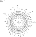
- the interior reinforcement body 24 having the function and configuration that have been described above is made up of a plurality of (a total of 12 in this embodiment) reinforcement walls 26a, 26b, a plurality of (six in the illustrated embodiment) radially inward continuous walls 27, 27 and a central reinforcement portion 28.
- the reinforcement walls 26a, 26b make up a radially outward portion of the interior reinforcement body 24.
- the reinforcement walls 26a, 26b are arranged so as not to exist in a radial direction (radially) which passes through the piston center axis (O) in such a state that radially outward end portions (lengthwise end portions) of the reinforcement walls 26a, 26b are made to continue to the inner circumferential surface of the cylindrical wall portion 17 while axial end portions of the reinforcement walls 26a, 26b are made to continue to the inner surface of the bottom wall portion 18.
- the six reinforcement walls 26a, 26a are disposed at equal intervals in the circumferential direction while being inclined by a predetermined angle in a predetermined direction relative to the radial direction.
- the remaining six reinforcement walls 26b, 26b are disposed at equal intervals in the circumferential direction while being inclined by the same inclination angle as that at which the reinforcement walls 26a, 26 are inclined relative to the radial direction in an opposite direction to the direction in which the reinforcement walls 26a, 26a are inclined.
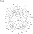
- the reinforcement walls 26a, 26a are provided in such a state that the reinforcement walls 26a, 26a are inclined by an inclination angle of + ⁇ relative to an imaginary line (Ra) in Fig.
- the reinforcement walls 26b, 26b are provided in such a state that the reinforcement walls 26b, 26b are inclined by an inclination angle of - ⁇ relative to an imaginary line (Rb) in Fig. 2 which denotes the radial direction as they extend radially inwards.
- the inclination of the reinforcement walls 26a, 26b relative to the radial direction means that center lines of the reinforcement walls 26a, 26b are so inclined relative to the radial direction.
- the reinforcement walls 26a, 26a and the reinforcement walls 26b, 26b which are inclined in the opposite directions relative to the radial direction, are disposed alternately in the circumferential direction.
- radially inward end portions of the pairs of reinforcement walls 26a, 26b which are inclined in directions in which they move towards each other as they extend radially inwards are connected together so as to form combined wall portions 29, 29 having substantially a V-like shape when seen from the front.
- These combined wall portions 29, 29 are provided at equal intervals in the circumferential direction.
- An axial thickness-wise dimension of the combined wall portions 29, 29 (the reinforcement walls 26a, 26b) is made to decrease as they extend radially inwards (towards the piston center axis (O)).
- first space portions 30, 30 and second space portions 31, 31, which are openings which open in the other axial direction, are formed alternately in the circumferential direction at the radially outward portion of the interior reinforcement body 24.
- the first space portions 30, 30 are formed at portions held by the pairs of reinforcement walls 26a, 26b which make up the combined wall portions 29, 29.
- the first space portions 30, 30 are each formed into a shape of an isosceles triangle with a curved base (a fan-like shape in Fig.
- the second space portions 31, 31 are formed between the combined wall portions 29, 29 which lie adjacent to each other in the circumferential direction.
- the second space portions 31, 31 are each formed into a shape of an isosceles triangle with a curved base (a hexagonal shape in Fig. 2 which is the reference drawing) and are disposed so that a vertical angle lies radially outwards while the base lies radially inwards.
- the first space portions 30, 30 and the second space portions 31, 31 are formed so that their angular corner portions are rounded so as to avoid the concentration of stress thereto.
- Axial dimensions of the first and second space portions 30, 31 are smaller by a slight amount (on the order one- to two-tenth an overall axial dimension) than an axial dimension of portions of the interior reinforcement body 24 which are offset circumferentially from the first and second space portions 30, 31. Because of this, bottom surfaces (axial side surfaces) of the first and second space portions 30, 31 do not reach the bottom wall portion 18 and are situated slightly nearer to the other axial side than the inner surface of the bottom wall portion 18. By adopting this configuration, even the portions where the first and second space portions 30, 31 are formed can contribute to the enhancement in strength of the bottom wall portion 18.
- the radially inward continuous walls 27, 27 make up a radial middle portion of the interior reinforcement body 24 and are disposed radially. Radially outward end portions of the radially inward continuous walls 27, 27 continue to the connecting portions (the radially inward end portions) of the pairs of reinforcement walls 26a, 26b which make up the combined wall portions 29, 29.
- a lengthwise dimension of the radially inward continuous walls 27, 27 is set shorter than lengthwise dimensions of the reinforcement walls 26a, 26b, whereas a thickness-wise dimension of the radially inward continuous walls 27, 27 is set greater than thickness-wise dimensions of the reinforcement walls 26a, 26b.
- the radially inward continuous walls 27, 27 which are configured in the way described above are provided individually between radially inward end portions of the second space portions 31, 31 in relation to the circumferential direction. As with the reinforcement walls 26a, 26b, an axial thickness-wise dimension of the radially inward continuous walls 27, 27 is made to decrease as they extend radially inwards (towards the piston center axis (O)).
- the central reinforcement portion 28 makes up a radially inward portion of the interior reinforcement body 24 and has a substantially circular ring shape when seen from the front. Because of this, the inner surface of the bottom wall portion 18 is exposed to a radially inward side (a circular portion including the piston center axis (O)) of the central reinforcement portion 28. An outer circumferential edge of the central reinforcement portion 28 continues to radially inward end portion of the radially inward continuous walls 27, 27 in six circumferential positions thereof.
- an axial thickness-wise dimension of the central reinforcement portion 28 is also made to decrease (to zero at a radially inner end portion) as it extends radially inwards (towards the piston center axis (O)).
- a hydraulic pressure is introduced into the cylinder space 20 (a pressurized brake oil is sent into the cylinder space 20), so that the piston 16 is pushed out towards the other axial side from the cylinder space 20.
- This brings the other axial end face of the piston 16 (the cylindrical wall portion 17) into abutment with the rear surface of the pressure plate 22 of the pad 21, whereby a lining of the pad 21 is pressed against a side surface of a rotor.
- the lining of the pad 21 and the side surface of the rotor are brought into sliding contact with each other, whereby the vehicle is slowed or stopped.
- the stress exerted on the outer circumferential surface of the cylindrical wall portion 17 is borne by the central reinforcement portion 28 by way of the reinforcement walls 26a, 26b (the combined wall portions 29) and the radially inward continuous walls 27, 27.
- radial compression stress is exerted on the reinforcement walls 26a, 26b and the radially inward continuous walls 27, 27, while radial compression stress and circumferential tensile stress are exerted on the central reinforcement portion 28.
- the stress exerted on the outer surface of the bottom wall portion 18 is borne by the reinforcement walls 26a, 26b, the radially inward continuous walls 27, 27 and the central reinforcement portion 28.
- the flexibility in design can be enhanced, whereby the ensured rigidity and the reduced weight can be made compatible at higher levels.
- the configuration is adopted in which the reinforcement walls 26a, 26b which continue to the inner circumferential surface of the cylindrical wall portion 17 and the inner surface of the bottom wall portion 18 exist not in the radial direction, in relation to the pairs of reinforcement walls 26a, 26b which lie adjacent to each other in the circumferential direction, the reinforcement walls 26a, 26b are inclined reversely or in the opposite direction relative to the radial direction, and the radially inward end portions of the reinforcement walls 26a, 26b are connected together (to thereby form the combined wall portions 29 having substantially the V-like shape when seen from the front), and by adopting this configuration, the design of high flexibility is realized.
- the lengthwise dimensions of the reinforcement walls 26a, 26b which make up the combined wall portions 29, 29 are made shorter than those of the reinforcement walls 26a, 26b which are arranged in the radial direction as described in the conventional construction shown in Fig. 14 , for example, whereby the weight of the piston 16 is reduced.
- the pair of reinforcement walls 26a, 26b which make up the different combined wall portions 29, 29 are inclined in the directions in which they move away further from each other as they extend radially inwards, and therefore, the second space portions 31, 31 each having a great volume are formed individually between the combined wall portions 29, 29 which lie adjacent to each other in the circumferential direction. Because of this, in the case of the first embodiment, a sufficient weight reduction can be realized. Consequently, even in a case where the radially inward continuous walls 27, 27 and the central reinforcement portion 28 are provided radially inwards of the combined wall portions 29, 29, it is possible to enhance the rigidity while suppressing the increase in overall weight of the piston 16.
- the reinforcement walls 26a, 26b are provided so as to be bifurcated from the radially outer end portions of the radially inward continuous walls 27, 27 which are arranged radially in a similar way to that of the conventional construction. Because of this, compared with a construction in which in place of the reinforcement walls 26a, 26b, the radially inward continuous walls 27, 27 are assumed to be extended radially outwards, the number of portions which support the inner circumferential surface of the cylindrical wall portion 17 can be doubled, and therefore, the rigidity of the piston 16 can be enhanced effectively.
- the piston 16 Since the piston 16 is formed into the bottomed cylindrical shape, a great bending moment is exerted on the cylindrical wall portion 17 at the axial end side which continues to the radially outer end portion of the bottom wall portion 18 rather than at the other axial end side. Then, in the case of the first embodiment, the axial thickness-wise dimension of the interior reinforcement body 24 is regulated so as to increase as it extends radially outwards (an inner bottom surface of the piston 16 is formed into a mortar-like shape), whereby the radial thickness-wise dimension of the interior reinforcement body 24 is ensured greatly at the axial end side portion of the cylindrical wall portion 17 on which the great bending moment is exerted.
- the ensured rigidity (the suppressed deformation) and the reduced weight can be made compatible at the cylindrical wall portion 17 and the bottom wall portion 18. Additionally, since the large spaces can be ensured in the interior of the piston 16, it is possible to insert a separate member into the piston 16.
- the axial position (X) of the other axial end edge of the radially outer end portion of the interior reinforcement body 24 which continues to the inner circumferential surface of the cylindrical wall portion 17 coincides with the axial position (Y) which constitutes the boundary position between the portions where the fluid pressure is borne and the portions where no fluid pressure is borne on the outer circumferential surface of the cylindrical wall portion 17, and the interior reinforcement body 24 is provided only at the radially inward portions of the portions on the outer circumferential surface of the cylindrical wall portion 17 where stress is exerted when braking.
- closed spaces 32, 32 of an isosceles triangular shape are provided individually in corner portions of reinforcement walls 26a, 26b, which make up a piston 16a, which exist at portions lying between an axial end portion of a cylindrical wall portion 17 and a radially outer end portion of a bottom wall portion 18.
- These corner portions have sufficiently high rigidity as a result of being held by the axial end portion of the cylindrical wall portion 17 and the radially outer end portion of the bottom wall portion 18 therebetween, even when the closed spaces 32, 32 are provided in the way described above, an interior reinforcement body 24 can still ensure the sufficient rigidity.
- the piston 16a of the second embodiment which has the closed spaces 32, 32 described above can be fabricated from metallic powder of aluminum alloy or iron-based alloy using a powder sintering method (SLS: Selective Laser Sintering) or can be fabricated using various solid shaping methods for fabricating a three-dimensional solid by laminating a material (for example, a fused deposition modeling method, an inkjet method, a powder binding method, an optical solid shaping method, a laser engineered net shaping (LENS) method, a fused metal deposition method (FDM)).
- SLS powder sintering method
- LENS laser engineered net shaping
- FDM fused metal deposition method
- the piston can be fabricated without using a special fabricating method by devising a shape for the piston so that closed spaces are formed between the interior reinforcement body and inner surface of the piston.
- an interior reinforcement body 24a which is provided inside a piston 16b is made up of six reinforcement walls 26c, 26d only. These reinforcement walls 26c, 26d are arranged so as not to exist in a radial direction (radially) which passes through a piston center axis (O) in such a state that radially outboard end portions (lengthwise end portions) thereof continue to an inner circumferential surface of a cylindrical wall portion 17 while axial end portions thereof continue to an inner surface of a bottom wall portion 18.
- three reinforcement walls 26c, 26c are disposed at equal intervals in a circumferential direction while being inclined by a predetermined angle in a predetermined direction relative to the radial direction.
- the remaining three reinforcement walls 26d, 26d are disposed at equal intervals in the circumferential direction in such a state that the reinforcement walls 26d, 26d are inclined relative to the radial direction by an angle equal to the angle at which the reinforcement walls 26c, 26c are inclined but in an opposite direction to the direction in which the reinforcement walls 26c, 26c are inclined.
- the reinforcement walls 26c, 26c are provided so as to be inclined by an inclination angle of + ⁇ relative to an imaginary line (Rc) in Fig. 8 which denotes the radial direction as they extend radially inward.
- the reinforcement walls 26d, 26d are provided so as to be inclined by an inclination angle or - ⁇ relative to an imaginary line (Rd) in Fig. 8 which denotes the radial direction as they extend radially inward.
- pairs of reinforcement walls 26c, 26d radially inward end portions of pairs of reinforcement walls 26c, 26d which are inclined so as to move towards each other as they extend radially inwards are connected together so as to form combined wall portions 29a, 29a of a V-like shape when seen from the front.
- first space portions 30a, 30a and a second space portion 31 a are formed which open to the other axial end side.
- the first space portions 30a, 30a are formed at portions lying between the pairs of reinforcement walls 26c, 26d which make up the combined wall portions 29a, 29a.
- the first space portions 30a, 30a have a shape of a triangle with a curved base when seen from the front (an isosceles triangular shape, a fan-like shape) and are disposed so that a vertical angle lies radially inwards while the base lies radially outwards.
- the second space portion 31a is made up by continuously combining spaces existing between the circumferentially adjacent combined wall portions 29a, 29a and a space existing radially inwards of the combined wall portions 29a, 29a and has a Y-like shape when seen from the front.
- the weight of the interior reinforcement body 24a can be reduced and the volume of the second space 31a can be increased, the weight of the interior reinforcement body 24a can be reduced further.
- a fourth embodiment of the invention will be described.
- a total of three radially inward continuous walls 27a, 27a are provided so as to continue to connecting portions where radially inward end portions of pairs of reinforcement walls 26c, 26d which make up combined wall portions 29a, 29a are connected together.
- circumferential end portions of the radially inward continuous walls 27a, 27a continue to connecting portions (radially inward end portions) of the circumferentially adjacent combined wall portions 29a, 29a.
- the radially inward continuous walls 27a, 27a are connected into a frame having a regular triangular shape (a frame having a regular polygonal shape) so as to surround a piston center axis (O).
- second space portions 31 b, 31 b having a substantially rectangular shape when seen from the front are formed individually between the circumferentially adjacent combined wall portions 29a, 29a, and a third space portion 33 having a regular triangular shape when seen from the front is formed inside the radially inward continuous walls 27a, 27a.
- the rigidity of a piston 16c (an interior reinforcement body 24b) can be increased further.
- the connecting portions of the combined wall portions 29a, 29a are made to continue to each other by way of the radially inward continuous walls 27a, 27a.
- the connecting portions of the combined wall portions 29a, 29a can also be made to continue to an outer circumferential edge of a central reinforcement portion having a substantially ring shape (or a circular shape) when seen from the front such as the one described in the first embodiment.
- the interior reinforcement body 24a is described as being made up of the total of three combined wall portions 29a, 29a.
- an interior reinforcement body 24c is made up of a total of four combined wall portions 29a, 29a.
- the configuration of a pair of reinforcement walls 26c, 26d which make up the combined wall portion 29a is the same as that of the third embodiment.
- a second space portion 31 c which is substantially cruciform when seen from the front is provided by combining spaces existing between the circumferentially adjacent combined wall portions 29a, 29a and a space existing radially inwards of the combined wall portions 29a, 29a.
- the rigidity can be increased. More specifically, since the number of combined wall portions 29a, 29a is increased, the rigidity can be balanced well in relation to the circumferential direction (a generation of portions having high circumferential rigidity and portions having low circumferential rigidity can be made difficult to occur).
- a sixth embodiment of the invention will be described.
- a total of four radially inward continuous walls 27b, 27b are provided so as to continue to connecting portions where radially inward end portions of pairs of reinforcement walls 26c, 26d which make up combined wall portions 29a, 29a are connected together.
- circumferential end portions of the radially inward continuous walls 27b, 27b continue to connecting portions (radially inward end portions) of the circumferentially adjacent combined wall portions 29a, 29a.
- the radially inward continuous walls 27b, 27b are connected into a frame having a rectangular shape (a frame having a regular polygonal shape) so as to surround a piston center axis (O).
- an interior reinforcement body 24d is configured into a shape resulting from piling parallel crosses when seen from the front.
- second space portions 31 d, 31 d having a substantially rectangular shape when seen from the front are formed individually between the circumferentially adjacent combined wall portions 29a, 29a, and a third space portion 33a having a square shape when seen from the front is formed inside the radially inward continuous walls 27b, 27b.
- the rigidity of a piston 16e (the interior reinforcement body 24d) can be increased further.
- the connecting portions of the combined wall portions 29a, 29a are made to continue to each other by way of the radially inward continuous walls 27b, 27b.
- the connecting portions of the combined wall portions 29a, 29a can also be made to continue to an outer circumferential edge of a central reinforcement portion having a substantially ring shape (or a circular shape) when seen from the front such as the one described in the first embodiment.
- an interior reinforcement body 24e which is provided inside a piston 16f is made up of a total of three reinforcement walls 26e, 26e.
- These reinforcement walls 26e, 26e are arranged so as not to exist in a radial direction (radially) which passes through a piston center axis (O) in such a state that lengthwise end portions thereof continue to an inner circumferential surface of a cylindrical wall portion 17.
- the reinforcement walls 26e, 26e are disposed at equal intervals (at intervals of 120°) in a circumferential direction while being inclined by an angle of 30 degrees in a predetermined direction relative to the radial direction.
- the reinforcement walls 26e, 26e are combined into a frame having a shape of a regular triangle which is inscribed to the cylindrical wall portion 17.
- first space portions 30b, 30b and a second space portion 31e are formed which open to the other axial end side.
- the first space portions 30b, 30b are formed at portions lying between the inner circumferential surface of the cylindrical wall portion 17 and outer surfaces of the reinforcement walls 26e, 26e and are formed into a bow shape when seen from the front.
- the second space portion 31e is formed inside the interior reinforcement body 24e and is formed into a shape of a regular triangle when seen from the front.
- the configuration is adopted in which the reinforcement walls 26e, 26e which continue to the inner circumferential surface of the cylindrical wall portion 17 and the inner surface of the bottom wall portion 18 do not exist in the radial direction and in which circumferential end portions of the reinforcement walls 26e, 26e continue to the inner circumferential surface of the cylindrical wall portion 17, and by adopting this configuration, the design of high flexibility is realized. Then, in the case of the seventh embodiment, by adopting the configuration described above, a lengthwise dimension of the reinforcement walls 26e, 26e becomes longer than when they are arranged radially.
- an interior reinforcement body with a frame of a regular quadrangle can also be formed using four reinforcement walls.
- an interior reinforcement body with a frame of a regular pentagon can also be formed using five reinforcement walls.
- the invention is not limited to the embodiments that have been described heretofore and hence can be modified or improved as required.
- the materials, shapes, dimensions, numbers and locations of the constituent elements which are described in the embodiments are arbitrary and are not limited thereto, as long as the invention can be attained.
- a two-piece construction may be adopted in which a piston includes a piston main body and a piston cap which is attached to a distal end portion of the piston main body.
- an interior reinforcement body can also be provided separately from a piston including a cylindrical wall portion and a bottom wall portion.
- a material from which the interior reinforcement body is formed can be different from a material from which the piston is formed.
- an axial position of the other axial end edge of a radially inward end portion of the interior reinforcement body which continues to an inner circumferential surface of the cylindrical wall portion coincides with an axial position of an axial end edge of a piston seal.
- the invention is not limited to that construction, and hence, the axial position of the other axial end edge of the interior reinforcement body can also be disposed closer to the other axial end side than the axial position of the piston seal.
- An axial thickness-wise dimension of the interior reinforcement body is not limited to that described in the constructions of the embodiments and hence can be changed as required according to locations, numbers and dimensions of reinforcement walls which make up the interior reinforcement body.
Landscapes
- Engineering & Computer Science (AREA)
- General Engineering & Computer Science (AREA)
- Mechanical Engineering (AREA)
- Braking Arrangements (AREA)
Abstract
Description
- The present invention relates to an improvement of a piston for a disc brake device.
- Disc brakes are widely used to slow or stop a motor vehicle. When a disc brake is used to slow or stop a vehicle, a pair of pads which are provided so as to hold therebetween a rotor rotating together with a wheel are caused to press against both sides of the rotor by a piston. As a disc brake device like the one described above, a floating-type disc brake device is in use in which the pair of pads described above are supported on a support which is fixed to a suspension system so as to be displaced freely. In the case of this floating-type disc brake, the piston described above is provided only one side (an inboard side which faces a transverse center of a vehicle body with the floating-type disc brake device mounted on the motor vehicle) of the rotor.
- In contrast with this floating-type disc brake device, in recent years, opposed-piston-type disc brake devices that pistons are provided at both sides of the rotor and the pair of pads are pressed against both sides of the rotor by these pistons when the disc brakes are used are also widely used particularly on high-performance vehicles for the reason that superior braking force can be obtained therewith.
- In these opposed-piston-type disc brake devices, an opposed-piston-type disc brake device described in
Patent Literature 1 is shown inFigs. 13 to 14 . This opposed-piston-typedisc brake device 1 includes a caliper 5 which is made up of an inboard body portion 3 and an outboard body portion 4 in a position where arotor 2 is held. Aninboard cylinder space 6 and anoutboard cylinder space 7 are provided in the inboard body portion 3 and the outboard body portion 4, respectively, in such a way that their openings face each other across therotor 2. Then, aninboard piston 8 and anoutboard piston 9 are fitted in theinboard piston space 6 and theoutboard piston space 7, respectively, in a fluid-tight fashion and in such a way as to move in an axial direction of therotor 2. Additionally, aninboard pad 10 is supported in the inboard body portion 3 so as to be displaced in the axial direction of therotor 2, and anoutboard pad 11 is supported in the outboard body portion 4 so as to be displaced in the axial direction of therotor 2. When braking, a fluid is sent under pressure into theinboard cylinder space 6 and theoutboard cylinder space 7, whereby theinboard pad 10 and theoutboard pad 11 are pressed against the corresponding sides of therotor 2 by theinboard piston 8 and theoutboard piston 9, respectively. - The inboard and
outboard pistons cylindrical wall portion 12 having a cylindrical shape and abottom wall portion 13 having a disc shape. Thebottom wall portion 13 closes an axial end side of thecylindrical wall portion 12 which lies on a deeper side of each of the inboard andoutboard cylinder spaces - A substantially
cylindrical projecting portion 14 is formed at a central portion of an inner surface of thebottom wall portion 13 which makes up each of the inboard andoutboard pistons straight reinforcement ribs bottom wall portion 13 so as to extend in a radial direction (radially) to thereby continue to an outer circumferential surface of the projectingportion 14 and an inner circumferential surface of thecylindrical wall portion 12. By adopting this configuration, the inboard andoutboard pistons outboard pistons outboard cylinder spaces - In the case of the inboard and
outboard pistons straight reinforcement ribs reinforcement ribs reinforcement ribs outboard pistons - Patent Literature 1:
JP 2011-102598 A - The invention has been made in view of the situations described above to realize a construction for a piston which is incorporated in a disc brake device which enables the ensured rigidity and the reduced weight to be made compatible at higher levels by enhancing the flexibility in design.
- The above object of the invention is achieved by the following configurations.
- (1) A piston for a disc brake device, which is fitted in a cylinder space formed in a caliper of the disc brake device so as to move in an axial direction, the piston including:
- a cylindrical wall portion having a cylindrical shape; and
- a bottom wall portion closing an end side of the cylindrical wall portion at one end thereof in the axial direction which lies on a deeper side of the cylinder space, wherein
- the piston has a bottomed cylindrical shape as a whole,
- at least three reinforcement walls are provided so as to continue to an inner circumferential surface of the cylindrical wall portion and an inner surface of the bottom wall portion, the reinforcement walls exist not in a radial direction which passes through a piston center axis, and
- an interior reinforcement body, which includes at least the reinforcement walls and is provided radially inwards of the cylindrical wall portion, is rotationally symmetric with respect to the piston center axis as a center thereof.
- (2) The piston for a disc brake device according to the above (1), wherein
radially inward end portions of a pair of the reinforcement walls which are adjacent to each other in a circumferential direction and which are inclined reversely relative to the radial direction are connected together so as to form a combined wall portion. - (3) The piston for a disc brake device according to the above (2), wherein
a radially inward continuous wall is provided radially inwards of a connecting portion of the radially inward end portions of the pair of the reinforcement walls forming the combined wall portion,
at least one end portion of the radially inward continuous wall continues to the connecting portion, and
the radially inward continuous wall forms the interior reinforcement body together with the corresponding reinforcement wall. - (4) The piston for a disc brake device according to the above (3), wherein
the radially inward continuous wall is disposed in the radial direction which passes through the piston center axis. - (5) The piston for a disc brake device according to the above (3), wherein
both end portions of the radially inward continuous wall continue to a pair of the connecting portions which are adjacent to each other in the circumferential direction. - (6) The piston for a disc brake device according to any one of the above (1) to (5), wherein
an axially thickness-wise dimension of the interior reinforcement body from the inner surface of the bottom wall portion gradually increases as the interior reinforcement body extends radially outwards from a center of the bottom wall portion, and
an axial position of an edge of a radially outer end portion of the interior reinforcement body at the other end thereof in the axial direction which continues to the inner circumferential surface of the cylindrical wall portion is situated in a boundary position between a portion where a fluid pressure is borne and a portion where no fluid pressure is borne on an outer circumferential surface of the cylindrical wall portion or a position which lies closer to the other end side than the boundary position in the axial direction. - (7) The piston for a disc brake device according to the above (1), wherein
the reinforcement walls are connected into a frame of a regular polygonal shape, and
the interior reinforcement body is formed by only the reinforcement walls. - (8) The piston for a disc brake device according to any one of the above (1) to (7), wherein
a closed space is provided in a corner portion of each of the reinforcement walls which exists at a portion held between an axial end portion of the cylindrical wall portion and a radially outer end portion of the bottom wall portion. - According to the disc brake device piston of the invention which is configured in the ways described above, the ensured rigidity and the reduce weight can be made compatible at higher levels by enhancing the flexibility in design.
- Namely, in the case of the invention, the reinforcement walls which continue to the inner circumferential surface of the cylindrical wall portion and the inner surface of the bottom wall portion which make up the piston and which make up the interior reinforcement body are arranged in such a way that the reinforcement walls do not exist in the radial direction which passes through the piston center axis on the premise that the interior reinforcement body is rotationally symmetric with respect to the piston center axis as the center thereof.
- Because of this, according to the invention, the reinforcement walls can be designed with the high flexibility by adopting, for example, the configuration as described under (2) in which the pair of reinforcement walls which lie adjacent to each other in the circumferential direction are inclined reversely relative to the radial direction and the radially inward end portions of both the reinforcement walls are connected together (at the portion other than the piston center) or the configuration in which the lengthwise end portions of the reinforcement walls are made to continue to the inner circumferential surface of the cylindrical wall portion. Namely, in addition to the thickness-wise dimension of the reinforcement walls and the number of reinforcement walls to be provided, the direction in which the reinforcement walls are set (the direction in which the reinforcement walls are inclined relative to the radial direction, the angle at which the reinforcement walls are inclined) and the lengthwise dimension of the reinforcement walls can also be changed as required. Consequently, according to the invention, it is easy to design the disc brake device piston so that the ensured rigidity and the reduced weight are made compatible at higher levels.
- According to the configuration described under (2) above, the lengthwise dimension of the reinforcement walls which make up the combined wall portion can be made shorter than when the reinforcement walls are arranged in the radial direction. Therefore, a reduction in weight of the disc brake device piston can be facilitated. In the pairs of reinforcement walls which lie adjacent to each other in the circumferential direction, the pair of reinforcement walls which make up the different combined wall portions are inclined so as to move away from each other as they extend radially inwards. Therefore, a large space can be formed between the combined wall portions which lie adjacent to each other in the circumferential direction. Because of this, a sufficient reduction in weight can be realized. Consequently, as in the configurations described under, for example, (3) to (5) above, even when the radially inward continuous walls are provided radially inwards of the combined wall portions so as to realize a further enhancement in rigidity, a reduction in weight of the disc brake device piston can be realized by suppressing an increase in overall weight thereof.
- According to the configuration described under (6) above, the ensured rigidity and the reduced weight of the cylindrical wall portion and the bottom wall portion can be made compatible. In addition, the large spaces can be ensured in the interior of the piston, and therefore, a separate member can also be inserted thereinto. Further, the axial position of the radially outer end portion of the interior reinforcement body is regulated, and therefore, the sufficient rigidity can be ensured for the cylindrical wall portion, thereby making it possible to prevent an occurrence of a deformation in the cylindrical wall portion effectively.
- Further, according to the configuration described under (8) above, the closed space is provided in the corner portion of each of the reinforcement walls where the sufficiently high rigidity is provided by being held between the axial end portion of the cylindrical wall portion and the radially outer end portion of the bottom wall portion, and therefore, a reduction in weight of the disc brake device piston can be realized while ensuring the sufficient rigidity.
-
- [
Fig. 1] Fig. 1 is a front view of a disc brake device piston showing a first embodiment of the invention. - [
Fig. 2] Fig. 2 is a schematic diagram corresponding to the front view of the disc brake device piston shown inFig. 1 . - [
Fig. 3] Fig. 3 is a bottom view of the disc brake device piston shown inFig. 1 . - [
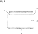
Fig. 4] Fig. 4 is a side view of the disc brake device piston shown inFig. 1 . - [
Fig. 5] Fig. 5 is a sectional view of the disc brake device piston taken along a line (A)-(O)-(A) shown inFig. 1 . - [
Fig. 6] Fig. 6 is a perspective view of the disc brake device piston shown inFig. 1 . - [
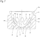
Fig. 7] Fig. 7 is a sectional view, corresponding toFig. 5 , showing a disc brake device piston according to a second embodiment of the invention. - [
Fig. 8] Fig. 8 is a schematic view, corresponding to a front view, of a disc brake device piston according to a third embodiment of the invention. - [
Fig. 9] Fig. 9 is a schematic view, corresponding to a front view, of a disc brake device piston according to a fourth embodiment of the invention. - [
Fig. 10] Fig. 10 is a schematic view, corresponding to a front view, of a disc brake device piston according to a fifth embodiment of the invention. - [
Fig. 11] Fig. 11 is a schematic view, corresponding to a front view, of a disc brake device piston according to a sixth embodiment of the invention. - [
Fig. 12] Fig. 12 is a schematic view, corresponding to a front view, of a disc brake device piston according to a seventh embodiment of the invention. - [
Fig. 13] Fig. 13 is a sectional view showing a conventional opposed-piston-type disc brake device. - [
Fig. 14] Fig. 14 is a front view of a piston which is removed from the disc brake device shown inFig. 13 . - Referring to
Figs. 1 to 6 , a first embodiment of the invention will be described. As in the case of the piston of the conventional construction shown inFig. 13 , when in use, apiston 16 of a first embodiment is incorporated in an opposed-piston-type disc brake device or a floating-type disc brake device. The overall construction of the opposed-piston-type disc brake device has already been described, and the overall construction of the floating-type disc brake device has widely been known, and the overall constructions of these disc brake devices are not a gist of the invention. Thus, a description of the construction of a disc brake device in which thepiston 16 is incorporated will be omitted here. In addition, in a case where thepiston 16 of this embodiment is incorporated in the opposed-piston-type disc brake device, thepiston 16 can be incorporated as either of an inboard piston and an outboard piston. - The
piston 16 is formed into a single integral unit as a whole by cutting and shaping a material of light metal such as aluminum alloy or injecting a thermosetting resin such as phenol resin into such an integral unit. In the case of the first embodiment, thepiston 16 includes acylindrical wall portion 17 having a cylindrical shape and abottom wall portion 18 having a disc shape and is formed into a bottomed cylindrical shape as a whole. - Of these constituent elements of the
piston 16, thecylindrical wall portion 17 has an outside diameter dimension which is slightly smaller than a bore diameter dimension of acylinder space 20 formed in acaliper 19. With thepiston 16 fitted in thecylinder space 20 so as to move in an axial direction, the other axial end face (an upper end face inFigs. 4 ,5 ) of thecylindrical wall portion 17 lies close to or is in abutment with a rear surface of apressure plate 22 which makes up apad 21. Aboot groove 23 is formed along a full length of an outer circumferential surface of the other axial end portion of thecylindrical wall portion 17 so as to be depressed radially inwards. Then, a boot, which is configured to prevent the intrusion of foreign matters into thecylinder space 20, can be fitted between theboot groove 23 and an opening portion of thecylinder space 20. - With the
piston 16 fitted in thecylinder space 20, thebottom wall portion 18 closes an axial end side (a lower end side inFigs. 4 ,5 ) of thecylindrical wall portion 17 which is situated on a deeper side of thecylinder space 20. In the case of the first embodiment, an outer surface (an axial side surface) of thebottom wall portion 18 is formed into a flat plane. Although an illustration is omitted, a plurality of depressions can also be formed on the outer surface of the bottom wall portion to reduce the weight of thepiston 16. - In particular, in the case of this first embodiment, an
interior reinforcement body 24 is provided integrally with thepiston 16 inside the piston 16 (radially inwards of the cylindrical wall portion 17). Thisinterior reinforcement body 24 is provided so as to continue individually to an inner circumferential surface of thecylindrical wall portion 17 and an inner surface (the other axial side surface) of thebottom wall portion 18 and prevents an occurrence of a deformation in thecylindrical wall portion 17 and thebottom wall portion 18 irrespective of a stress (a brake fluid pressure) which is exerted on an outer circumferential surface of thecylindrical portion 17 and the outer surface (the axial side surface) of thebottom wall portion 18 when braking. A boundary position between theinterior reinforcement body 24 and thecylindrical wall portion 17 and thebottom wall portion 18 is indicted by a chain double-dashed line inFig. 5 . In the case of the first embodiment, theinterior reinforcement body 24 is rotationally symmetric with respect to a piston center axis (O) of the piston. The reason for configuring theinterior reinforcement body 24 in that way is that the balance in radial rigidity is prevented from being lost (the generation of high rigid portions and low rigid portions is prevented) in circumferential positions on the outer circumferential surface of thecylindrical wall portion 17 due to stress being exerted equally along the length of the outer circumferential surface in the circumferential direction. - The
interior reinforcement body 24 makes up an inner circumferential wall and an inner bottom wall of thepiston 16 together with thecylindrical wall portion 17 and thebottom wall portion 18. An axial thickness-wise dimension of theinterior reinforcement body 24 measured from the inner surface (Z) of thebottom wall portion 18 increases into a smooth curve as it extends radially outwards from a center of the bottom wall portion 18 (a portion of thebottom wall portion 18 which passes through the piston center axis (O)). Because of this, an inner bottom surface of thepiston 16 which is made up of the other axial side surface of theinterior reinforcement body 24 is formed into a mortar-like shape (or a shape of a concavely depressed surface) whose bottom portion is made up of a central portion through which the piston center axis (O) passes. - In the case of the first embodiment, an axial position (X) of the other axial end edge of a radially outer end portion of the
interior reinforcement body 24 which continues to the inner circumferential surface of thecylindrical wall portion 17 is regulated as follows. Namely, this axial position (X) coincides with an axial position (Y) of an axial end edge of apiston seal 25 which is mounted on an axial middle portion of thecylinder space 20 which corresponds to a boundary position between a portion where a fluid pressure is borne and a portion where no fluid pressure is borne on the outer circumferential surface of thecylindrical wall portion 17. By adopting this configuration, theinterior reinforcement body 24 is designed to be provided only at radially inward portions of the portions on the outer circumferential surface of thecylindrical wall portion 17 where stress is borne when braking. In other words, theinterior reinforcement portion 24 is not provided at radially inward portions of the portions on the outer circumferential surface of thecylindrical wall portion 17 where no stress is borne. - The
piston seal 25 has a rectangular cross-sectional shape and is formed into an annular shape as a whole. Thepiston seal 25 is brought into sliding contact with an outer circumferential surface of an axial middle portion of thecylindrical wall 17 in a fluid-tight fashion so as to move with respect to the outer circumferential surface of the axial middle portion. When the brake is released, thepiston seal 25 moves (rolls back) thepiston 16 towards the deeper side of thecylinder space 20 by the elastic restoring force. - In the case of the first embodiment, the
interior reinforcement body 24 having the function and configuration that have been described above is made up of a plurality of (a total of 12 in this embodiment)reinforcement walls continuous walls central reinforcement portion 28. - The
reinforcement walls interior reinforcement body 24. Thereinforcement walls reinforcement walls cylindrical wall portion 17 while axial end portions of thereinforcement walls bottom wall portion 18. - Specifically speaking, in the 12
reinforcement walls reinforcement walls reinforcement walls reinforcement walls 26a, 26 are inclined relative to the radial direction in an opposite direction to the direction in which thereinforcement walls reinforcement walls reinforcement walls Fig. 2 which denotes the radial direction as they extend radially inwards. Additionally, thereinforcement walls reinforcement walls Fig. 2 which denotes the radial direction as they extend radially inwards. The inclination of thereinforcement walls reinforcement walls - Then, the
reinforcement walls reinforcement walls reinforcement walls reinforcement walls wall portions wall portions wall portions 29, 29 (thereinforcement walls - In the case of the first embodiment, as a result of the radially outward portion of the
interior reinforcement body 24 being configured in the way described above,first space portions second space portions interior reinforcement body 24. Of these first and second space portions, thefirst space portions reinforcement walls wall portions first space portions Fig. 2 which is a reference drawing) and are disposed so that a vertical angle lies radially inwards while the base lies radially outwards. In contrast with this, thesecond space portions wall portions second space portions Fig. 2 which is the reference drawing) and are disposed so that a vertical angle lies radially outwards while the base lies radially inwards. In the case of the first embodiment, thefirst space portions second space portions second space portions interior reinforcement body 24 which are offset circumferentially from the first andsecond space portions second space portions bottom wall portion 18 and are situated slightly nearer to the other axial side than the inner surface of thebottom wall portion 18. By adopting this configuration, even the portions where the first andsecond space portions bottom wall portion 18. - The radially inward
continuous walls interior reinforcement body 24 and are disposed radially. Radially outward end portions of the radially inwardcontinuous walls reinforcement walls wall portions continuous walls reinforcement walls continuous walls reinforcement walls continuous walls second space portions reinforcement walls continuous walls - The
central reinforcement portion 28 makes up a radially inward portion of theinterior reinforcement body 24 and has a substantially circular ring shape when seen from the front. Because of this, the inner surface of thebottom wall portion 18 is exposed to a radially inward side (a circular portion including the piston center axis (O)) of thecentral reinforcement portion 28. An outer circumferential edge of thecentral reinforcement portion 28 continues to radially inward end portion of the radially inwardcontinuous walls reinforcement walls continuous walls central reinforcement portion 28 is also made to decrease (to zero at a radially inner end portion) as it extends radially inwards (towards the piston center axis (O)). - In slowing or stopping a vehicle such as a motor vehicle using the disc brake device in which the
piston 16 of the first embodiment is incorporated which is configured in the way described heretofore, a hydraulic pressure is introduced into the cylinder space 20 (a pressurized brake oil is sent into the cylinder space 20), so that thepiston 16 is pushed out towards the other axial side from thecylinder space 20. This brings the other axial end face of the piston 16 (the cylindrical wall portion 17) into abutment with the rear surface of thepressure plate 22 of thepad 21, whereby a lining of thepad 21 is pressed against a side surface of a rotor. Then, the lining of thepad 21 and the side surface of the rotor are brought into sliding contact with each other, whereby the vehicle is slowed or stopped. - Then, when braking in the way described above, stress generated based on the brake oil is exerted on the outer circumferential surface of the
cylindrical wall portion 17 and the outer surface of thebottom wall portion 18. More specifically, radially inward stress is exerted evenly in the circumferential direction on a portion of the outer circumferential surface of thecylindrical wall portion 17 which lies closer to the axial end side than the axial position (Y) (the axial position of the axial end edge of the piston seal 25). Additionally, stress directed towards the other axial side is exerted evenly on the outer surface of thebottom wall portion 18. In the case of the first embodiment, since theinterior reinforcement body 24 configured in the way described above is provided inside thepiston 16, although the stress is exerted as described above, an occurrence of a deformation in thecylindrical wall portion 17 and thebottom wall portion 18 can be prevented effectively. - Namely, the stress exerted on the outer circumferential surface of the
cylindrical wall portion 17 is borne by thecentral reinforcement portion 28 by way of thereinforcement walls continuous walls reinforcement walls continuous walls central reinforcement portion 28. In contrast with this, the stress exerted on the outer surface of thebottom wall portion 18 is borne by thereinforcement walls continuous walls central reinforcement portion 28. - According to the
piston 16 of the first embodiment which is configured in the way described above, the flexibility in design can be enhanced, whereby the ensured rigidity and the reduced weight can be made compatible at higher levels. - Namely, in the case of the first embodiment, the configuration is adopted in which the
reinforcement walls cylindrical wall portion 17 and the inner surface of thebottom wall portion 18 exist not in the radial direction, in relation to the pairs ofreinforcement walls reinforcement walls reinforcement walls wall portions 29 having substantially the V-like shape when seen from the front), and by adopting this configuration, the design of high flexibility is realized. Then, in the case of the first embodiment, by adopting the configuration described above, the lengthwise dimensions of thereinforcement walls wall portions reinforcement walls Fig. 14 , for example, whereby the weight of thepiston 16 is reduced. In the pairs ofreinforcement walls reinforcement walls wall portions second space portions wall portions continuous walls central reinforcement portion 28 are provided radially inwards of the combinedwall portions piston 16. In the case of the first embodiment, thereinforcement walls continuous walls reinforcement walls continuous walls cylindrical wall portion 17 can be doubled, and therefore, the rigidity of thepiston 16 can be enhanced effectively. - Since the
piston 16 is formed into the bottomed cylindrical shape, a great bending moment is exerted on thecylindrical wall portion 17 at the axial end side which continues to the radially outer end portion of thebottom wall portion 18 rather than at the other axial end side. Then, in the case of the first embodiment, the axial thickness-wise dimension of theinterior reinforcement body 24 is regulated so as to increase as it extends radially outwards (an inner bottom surface of thepiston 16 is formed into a mortar-like shape), whereby the radial thickness-wise dimension of theinterior reinforcement body 24 is ensured greatly at the axial end side portion of thecylindrical wall portion 17 on which the great bending moment is exerted. Consequently, in the case of the first embodiment, the ensured rigidity (the suppressed deformation) and the reduced weight can be made compatible at thecylindrical wall portion 17 and thebottom wall portion 18. Additionally, since the large spaces can be ensured in the interior of thepiston 16, it is possible to insert a separate member into thepiston 16. - The axial position (X) of the other axial end edge of the radially outer end portion of the
interior reinforcement body 24 which continues to the inner circumferential surface of thecylindrical wall portion 17 coincides with the axial position (Y) which constitutes the boundary position between the portions where the fluid pressure is borne and the portions where no fluid pressure is borne on the outer circumferential surface of thecylindrical wall portion 17, and theinterior reinforcement body 24 is provided only at the radially inward portions of the portions on the outer circumferential surface of thecylindrical wall portion 17 where stress is exerted when braking. This allows the interior reinforcement body 24 (thereinforcement walls cylindrical portion 17 effectively while suppressing the increase in weight which would be attributed to the provision of theinterior reinforcement body 24 to a minimum level. - Referring to
Fig. 7 , a second embodiment of the invention will be described. In the case of the second embodiment, closedspaces reinforcement walls piston 16a, which exist at portions lying between an axial end portion of acylindrical wall portion 17 and a radially outer end portion of abottom wall portion 18. These corner portions have sufficiently high rigidity as a result of being held by the axial end portion of thecylindrical wall portion 17 and the radially outer end portion of thebottom wall portion 18 therebetween, even when theclosed spaces interior reinforcement body 24 can still ensure the sufficient rigidity. Thus, it is possible to reduce the weight of thepiston 16a while ensuring the sufficient rigidity. - The
piston 16a of the second embodiment which has the closedspaces - The other configurations and working effects are the same as those of the first embodiment described above.
- Referring to
Fig. 8 , a third embodiment of the invention will be described. In the case of the third embodiment, aninterior reinforcement body 24a which is provided inside apiston 16b is made up of sixreinforcement walls reinforcement walls cylindrical wall portion 17 while axial end portions thereof continue to an inner surface of abottom wall portion 18. - Specifically speaking, in the total of six
reinforcement walls reinforcement walls reinforcement walls reinforcement walls reinforcement walls reinforcement walls reinforcement walls Fig. 8 which denotes the radial direction as they extend radially inward. Thereinforcement walls Fig. 8 which denotes the radial direction as they extend radially inward. Then, in pairs ofreinforcement walls reinforcement walls wall portions - In the case of the third embodiment, as a result of the
interior reinforcement body 24a being configured in the way described above,first space portions second space portion 31 a are formed which open to the other axial end side. In these space portions, thefirst space portions reinforcement walls wall portions first space portions second space portion 31a is made up by continuously combining spaces existing between the circumferentially adjacent combinedwall portions wall portions - In the case of the third embodiment configured in the way described above, compared with the case of the first embodiment, since the weight of the
interior reinforcement body 24a can be reduced and the volume of thesecond space 31a can be increased, the weight of theinterior reinforcement body 24a can be reduced further. - The other configurations and working effects are the same as those of the first embodiment described above.
- Referring to
Fig. 9 , a fourth embodiment of the invention will be described. In the case of the fourth embodiment, with a view to increasing the rigidity more than that provided by the construction of the third embodiment, a total of three radially inwardcontinuous walls reinforcement walls wall portions continuous walls wall portions continuous walls second space portions wall portions third space portion 33 having a regular triangular shape when seen from the front is formed inside the radially inwardcontinuous walls - In the case of the fourth embodiment configured in the way described above, the rigidity of a
piston 16c (aninterior reinforcement body 24b) can be increased further. In the case of the fourth embodiment, the connecting portions of the combinedwall portions continuous walls wall portions - The other configurations and working effects are the same as those of the first and third embodiments described above.
- Referring to
Fig. 10 , a fifth embodiment of the invention will be described. In the case of the third embodiment described above, theinterior reinforcement body 24a is described as being made up of the total of three combinedwall portions interior reinforcement body 24c is made up of a total of four combinedwall portions reinforcement walls wall portion 29a is the same as that of the third embodiment. Asecond space portion 31 c which is substantially cruciform when seen from the front is provided by combining spaces existing between the circumferentially adjacent combinedwall portions wall portions - In the case of the fifth embodiment configured in the way described above, compared with the case of the third embodiment described above, the rigidity can be increased. More specifically, since the number of combined
wall portions - The other configurations and working effects are the same as those of the first and third embodiments described above.
- Referring to
Fig. 11 , a sixth embodiment of the invention will be described. In the case of the sixth embodiment, with a view to increasing the rigidity more than that provided by the construction of the fifth embodiment, a total of four radially inwardcontinuous walls reinforcement walls wall portions continuous walls wall portions continuous walls interior reinforcement body 24d is configured into a shape resulting from piling parallel crosses when seen from the front. Additionally, in the case of the sixth embodiment,second space portions wall portions third space portion 33a having a square shape when seen from the front is formed inside the radially inwardcontinuous walls - In the case of the sixth embodiment configured in the way described above, the rigidity of a piston 16e (the
interior reinforcement body 24d) can be increased further. In the case of the sixth embodiment, the connecting portions of the combinedwall portions continuous walls wall portions - The other configurations and working effects are the same as those of the first and fifth embodiments described above.
- Referring to
Fig. 12 , a seventh embodiment of the invention will be described. In the case of the seventh embodiment, aninterior reinforcement body 24e which is provided inside apiston 16f is made up of a total of threereinforcement walls reinforcement walls cylindrical wall portion 17. Specifically, thereinforcement walls reinforcement walls cylindrical wall portion 17. - In the case of the seventh embodiment, since the
interior reinforcement body 24e is configured in the way described above,first space portions second space portion 31e are formed which open to the other axial end side. In these space portions, thefirst space portions cylindrical wall portion 17 and outer surfaces of thereinforcement walls second space portion 31e is formed inside theinterior reinforcement body 24e and is formed into a shape of a regular triangle when seen from the front. - In the case of the seventh embodiment configured in the way described above, the configuration is adopted in which the
reinforcement walls cylindrical wall portion 17 and the inner surface of thebottom wall portion 18 do not exist in the radial direction and in which circumferential end portions of thereinforcement walls cylindrical wall portion 17, and by adopting this configuration, the design of high flexibility is realized. Then, in the case of the seventh embodiment, by adopting the configuration described above, a lengthwise dimension of thereinforcement walls reinforcement walls cylindrical wall portion 17, the rigidity can be well balanced in relation to the radial direction of the cylindrical wall portion 17 (a generation of portions having high circumferential rigidity and portions having low circumferential rigidity can be made difficult to occur) although the number of reinforcement walls to be provided becomes smaller than when they are arranged in the radial direction (although only three reinforcement walls are provided as in this embodiment). In addition, since the weight of theinterior reinforcement body 24e can be reduced and a great volume can be ensured in thesecond space portion 31 e, a sufficient reduction in weight can be realized. Consequently, the ensured rigidity and the reduced weight can be made compatible at higher levels. As a modified example of the seventh embodiment, an interior reinforcement body with a frame of a regular quadrangle can also be formed using four reinforcement walls. Additionally, an interior reinforcement body with a frame of a regular pentagon can also be formed using five reinforcement walls. - The other configurations and working effects are the same as those of the first embodiment.
- Here, the characteristics of the embodiments of the disc brake device piston according to the invention will briefly be summarized as follows.
- [1] A piston (the
piston 16 and thepistons 16 to 16f) for a disc brake device, which is fitted in a cylinder space (20) formed in a caliper (19) of the disc brake device so as to move in an axial direction, the piston including:- a cylindrical wall portion (17) having a cylindrical shape; and
- a bottom wall portion (18) closing an end side of the cylindrical wall portion at one end thereof in the axial direction which lies on a deeper side of the cylinder space (20), wherein
- the piston has a bottomed cylindrical shape as a whole,
- at least three reinforcement walls (26a) are provided so as to continue to an inner circumferential surface of the cylindrical wall portion and an inner surface of the bottom wall portion, to the reinforcement walls exist not in a radial direction which passes through a piston center axis (O), and
- an interior reinforcement body (24), which includes at least the reinforcement walls and is provided radially inwards of the cylindrical wall portion, is rotationally symmetric with respect to the piston center axis as a center thereof.
- [2] The piston (the
pistons
radially inward end portions of a pair of the reinforcement walls which are adjacent to each other in a circumferential direction and which are inclined reversely relative to the radial direction are connected together so as to form a combined wall portion (29, 29a). - [3] The piston (the
pistons
a radially inward continuous wall (27, 27a, 27b) is provided radially inwards of a connection portion of the radially inward end portions of the pair of the reinforcement walls forming the combined wall portion,
at least one end portion of the radially inward continuous wall continues to the connecting portion, and
the radially inward continuous wall forms the interior reinforcement body together with the corresponding reinforcement wall. - [4] The piston (the piston 16) for a disc brake device according to [3] above, wherein
the radially inward continuous wall is disposed in the radial direction which passes through the piston center axis. - [5] The piston (the
pistons 16c, 16e) for a disc brake device according to [3] above, wherein
both end portions of the radially inward continuous wall continue to a pair of the connecting portions which are adjacent to each other in the circumferential direction. - [6] The piston (the piston 16) for a disc brake device according to anyone of [1] to [5] above, wherein
an axially thickness-wise dimension of the interior reinforcement body from the inner surface of the bottom wall portion gradually increases as the interior reinforcement body extends radially outwards from a center of the bottom wall portion, and
an axial position (X) of an edge of a radially outer end portion of the interior reinforcement body at the other end thereof in the axial direction which continues to the inner circumferential surface of the cylindrical wall portion is situated in a boundary position (an axial position (Y) of an axial end edge of the piston seal 25) between a portion where a fluid pressure is borne and a portion where no fluid pressure is borne on an outer circumferential surface of the cylindrical wall portion or a position which lies closer to the other axial end side than the boundary position in the axial direction. - [7] The piston (the
pistons 16c, 16e) for a disc brake device according to [1] above, wherein
the reinforcement walls are connected into a frame of a regular polygonal shape,and
the interior reinforcement body is formed by only the reinforcement walls. - [8] The piston (the
piston 16a) for a disc brake device according to anyone of [1] to [7] above, wherein
a closed space (32) is provided in a corner portion of each of the reinforcement walls which exists at a portion held between an axial end portion of the cylindrical wall portion and a radially outer end portion of the bottom wall portion. - The invention is not limited to the embodiments that have been described heretofore and hence can be modified or improved as required. In addition, the materials, shapes, dimensions, numbers and locations of the constituent elements which are described in the embodiments are arbitrary and are not limited thereto, as long as the invention can be attained.
- Additionally, this patent application is based on Japanese Patent Application (No.
2015-085891) filed on April 20, 2015 - In carrying out the invention, a two-piece construction may be adopted in which a piston includes a piston main body and a piston cap which is attached to a distal end portion of the piston main body. Additionally, in carrying out the invention, an interior reinforcement body can also be provided separately from a piston including a cylindrical wall portion and a bottom wall portion. As this occurs, a material from which the interior reinforcement body is formed can be different from a material from which the piston is formed. Further, in carrying out the invention, an axial position of the other axial end edge of a radially inward end portion of the interior reinforcement body which continues to an inner circumferential surface of the cylindrical wall portion coincides with an axial position of an axial end edge of a piston seal. However, the invention is not limited to that construction, and hence, the axial position of the other axial end edge of the interior reinforcement body can also be disposed closer to the other axial end side than the axial position of the piston seal. An axial thickness-wise dimension of the interior reinforcement body is not limited to that described in the constructions of the embodiments and hence can be changed as required according to locations, numbers and dimensions of reinforcement walls which make up the interior reinforcement body.
-
- 1 disc brake device
- 2 rotor
- 3 inboard body portion
- 4 outboard body portion
- 5 caliper
- 6 inboard cylinder space
- 7 outboard cylinder space
- 8 inboard piston
- 9 outboard piston
- 10 inboard pad
- 11 outboard pad
- 12 cylindrical wall portion
- 13 bottom wall portion
- 14 projecting portion
- 15 reinforcement rib
- 16, 16a, 16b piston
- 17 cylindrical wall portion
- 18 bottom wall portion
- 19 caliper
- 20 cylinder space
- 21 pad
- 22 pressure plate
- 23 boot groove
- 24, 24a to 24e
interior reinforcement body 25 piston seal - 26a to 22e reinforcement wall
- 27, 27a, 27b radially inward continuous wall
- 28 central reinforcement portion
- 29, 29a combined wall portion
- 30, 30a, 30b first space portion
- 31, 31 a to 31 e second space portion
- 32 closed space
- 33, 33a third space portion.
Claims (8)
- A piston for a disc brake device, which is fitted in a cylinder space formed in a caliper of the disc brake device so as to move in an axial direction, the piston comprising:a cylindrical wall portion having a cylindrical shape; anda bottom wall portion closing an end side of the cylindrical wall portion at one end thereof in the axial direction which lies on a deeper side of the cylinder space, whereinthe piston has a bottomed cylindrical shape as a whole,at least three reinforcement walls are provided so as to continue to an inner circumferential surface of the cylindrical wall portion and an inner surface of the bottom wall portion, the reinforcement walls exist not in a radial direction which passes through a piston center axis, andan interior reinforcement body, which includes at least the reinforcement walls and is provided radially inwards of the cylindrical wall portion, is rotationally symmetric with respect to the piston center axis as a center thereof.
- The piston for a disc brake device according to Claim 1, wherein
radially inward end portions of a pair of the reinforcement walls which are adjacent to each other in a circumferential direction and which are inclined reversely relative to the radial direction are connected together so as to form a combined wall portion. - The piston for a disc brake device according to Claim 2, wherein
a radially inward continuous wall is provided radially inwards of a connecting portion of the radially inward end portions of the pair of the reinforcement walls forming the combined wall portion,
at least one end portion of the radially inward continuous wall continues to the connecting portion, and
the radially inward continuous wall forms the interior reinforcement body together with the corresponding reinforcement wall. - The piston for a disc brake device according to Claim 3, wherein
the radially inward continuous wall is disposed in the radial direction which passes through the piston center axis. - The piston for a disc brake device according to Claim 3, wherein
both end portions of the radially inward continuous wall continue to a pair of the connecting portions which are adjacent to each other in the circumferential direction. - The piston for a disc brake device according to any one of Claims 1 to 5, wherein
an axially thickness-wise dimension of the interior reinforcement body from the inner surface of the bottom wall portion gradually increases as the interior reinforcement body extends radially outwards from a center of the bottom wall portion, and
an axial position of an edge of a radially outer end portion of the interior reinforcement body at the other end thereof in the axial direction which continues to the inner circumferential surface of the cylindrical wall portion is situated in a boundary position between a portion where a fluid pressure is borne and a portion where no fluid pressure is borne on an outer circumferential surface of the cylindrical wall portion or a position which lies closer to the other end side than the boundary position in the axial direction. - The piston for a disc brake device according to Claim 1, wherein
the reinforcement walls are connected into a frame of a regular polygonal shape, and
the interior reinforcement body is formed by only the reinforcement walls. - The piston for a disc brake device according to any one of Claims 1 to 7, wherein
a closed space is provided in a corner portion of each of the reinforcement walls which exists at a portion held between an axial end portion of the cylindrical wall portion and a radially outer end portion of the bottom wall portion.
Applications Claiming Priority (2)
| Application Number | Priority Date | Filing Date | Title |
|---|---|---|---|
| JP2015085891A JP2016205485A (en) | 2015-04-20 | 2015-04-20 | Piston for disc brake device |
| PCT/JP2016/062424 WO2016171145A1 (en) | 2015-04-20 | 2016-04-19 | Piston for disc brake device |
Publications (2)
| Publication Number | Publication Date |
|---|---|
| EP3287658A1 true EP3287658A1 (en) | 2018-02-28 |
| EP3287658A4 EP3287658A4 (en) | 2018-12-19 |
Family
ID=57143097
Family Applications (1)
| Application Number | Title | Priority Date | Filing Date |
|---|---|---|---|
| EP16783166.8A Withdrawn EP3287658A4 (en) | 2015-04-20 | 2016-04-19 | Piston for disc brake device |
Country Status (5)
| Country | Link |
|---|---|
| US (1) | US20180106314A1 (en) |
| EP (1) | EP3287658A4 (en) |
| JP (1) | JP2016205485A (en) |
| CN (1) | CN107532665A (en) |
| WO (1) | WO2016171145A1 (en) |
Family Cites Families (9)
| Publication number | Priority date | Publication date | Assignee | Title |
|---|---|---|---|---|
| JPS56164238A (en) * | 1980-05-20 | 1981-12-17 | Akebono Brake Ind Co Ltd | Disc-shaped brake piston |
| MX153781A (en) * | 1980-08-28 | 1987-01-09 | Kelsey Hayes Co | IMPROVEMENTS IN HYDRAULIC PISTON FOR AUTOMOBILE BRAKE SYSTEMS |
| JPS614040U (en) * | 1984-06-15 | 1986-01-11 | 東京部品工業株式会社 | Piston in disc brake |
| DE4003731A1 (en) * | 1990-02-08 | 1991-08-14 | Teves Gmbh Alfred | COLD FORMED PISTON FOR HYDRAULIC WORKING BRAKE |
| US5105917A (en) * | 1990-12-31 | 1992-04-21 | Kelsey-Hayes Company | Disc brake piston |
| JPH04362327A (en) * | 1991-06-04 | 1992-12-15 | Nissin Kogyo Kk | Resin piston of disc brake for vehicle |
| DE19939873A1 (en) * | 1999-07-02 | 2001-01-04 | Continental Teves Ag & Co Ohg | Pistons for a hydraulic pressure chamber |
| JP2011102598A (en) * | 2009-11-10 | 2011-05-26 | Nissin Kogyo Co Ltd | Piston for vehicle disk brake |
| ITBS20130036A1 (en) * | 2013-03-18 | 2014-09-19 | Freni Brembo Spa | DISC BRAKE CALIPER WITH REDUCED AXIAL SIZE |
-
2015
- 2015-04-20 JP JP2015085891A patent/JP2016205485A/en active Pending
-
2016
- 2016-04-19 EP EP16783166.8A patent/EP3287658A4/en not_active Withdrawn
- 2016-04-19 WO PCT/JP2016/062424 patent/WO2016171145A1/en not_active Ceased
- 2016-04-19 US US15/567,634 patent/US20180106314A1/en not_active Abandoned
- 2016-04-19 CN CN201680023704.8A patent/CN107532665A/en not_active Withdrawn
Also Published As
| Publication number | Publication date |
|---|---|
| CN107532665A (en) | 2018-01-02 |
| WO2016171145A1 (en) | 2016-10-27 |
| EP3287658A4 (en) | 2018-12-19 |
| JP2016205485A (en) | 2016-12-08 |
| US20180106314A1 (en) | 2018-04-19 |
Similar Documents
| Publication | Publication Date | Title |
|---|---|---|
| EP2815148B1 (en) | Caliper body for disc brake | |
| US8485323B2 (en) | Caliper assembly for disc brake system | |
| US11965567B2 (en) | Disc brake | |
| CN103348166B (en) | Piston ring | |
| CN109312799B (en) | Brake caliper | |
| US11162550B2 (en) | Caliper for opposed piston type disc brake | |
| US9784329B2 (en) | Composite brake drum with bands | |
| US7344006B2 (en) | Piston assembly for use in a brake assembly | |
| EP3680504B1 (en) | Vehicular disc brake | |
| US10520053B2 (en) | Heat shield element | |
| EP3680502B1 (en) | Caliper for opposed piston-type disc brake | |
| CN111051723B (en) | Piston seal assembly for clutch release system and clutch release system | |
| JP6299411B2 (en) | Disc brake | |
| EP2796742A2 (en) | Caliper body for vehicle disc brake | |
| US20180106314A1 (en) | Piston for disc brake device | |
| CN104718398A (en) | Rebound rubber | |
| US20150167764A1 (en) | Friction material engagement of a friction member | |
| US20180172096A1 (en) | Piston and disc brake using same | |
| US11802600B2 (en) | Caliper body of a caliper for disc brake | |
| CN217081205U (en) | Anti-drop-top brake drum for automobile | |
| JP2024147007A (en) | Caliper body for disc brake and floating type disc brake device | |
| JP4461082B2 (en) | Caliper body for disc brakes for vehicles | |
| CN115247680B (en) | Calipers for opposed piston disc brakes | |
| JP2010112424A (en) | Opposed piston type disk brake | |
| JPH04362327A (en) | Resin piston of disc brake for vehicle |
Legal Events
| Date | Code | Title | Description |
|---|---|---|---|
| PUAI | Public reference made under article 153(3) epc to a published international application that has entered the european phase |
Free format text: ORIGINAL CODE: 0009012 |
|
| 17P | Request for examination filed |
Effective date: 20171019 |
|
| AK | Designated contracting states |
Kind code of ref document: A1 Designated state(s): AL AT BE BG CH CY CZ DE DK EE ES FI FR GB GR HR HU IE IS IT LI LT LU LV MC MK MT NL NO PL PT RO RS SE SI SK SM TR |
|
| AX | Request for extension of the european patent |
Extension state: BA ME |
|
| DAV | Request for validation of the european patent (deleted) | ||
| DAX | Request for extension of the european patent (deleted) | ||
| A4 | Supplementary search report drawn up and despatched |
Effective date: 20181120 |
|
| RIC1 | Information provided on ipc code assigned before grant |
Ipc: F16D 125/06 20120101ALI20181114BHEP Ipc: F16D 65/18 20060101AFI20181114BHEP Ipc: F16D 55/228 20060101ALI20181114BHEP Ipc: F16D 121/04 20120101ALI20181114BHEP |
|
| STAA | Information on the status of an ep patent application or granted ep patent |
Free format text: STATUS: THE APPLICATION IS DEEMED TO BE WITHDRAWN |
|
| 18D | Application deemed to be withdrawn |
Effective date: 20190618 |