EP3287553A1 - Systems and methods for air entanglement - Google Patents
Systems and methods for air entanglement Download PDFInfo
- Publication number
- EP3287553A1 EP3287553A1 EP17187449.8A EP17187449A EP3287553A1 EP 3287553 A1 EP3287553 A1 EP 3287553A1 EP 17187449 A EP17187449 A EP 17187449A EP 3287553 A1 EP3287553 A1 EP 3287553A1
- Authority
- EP
- European Patent Office
- Prior art keywords
- bedplate
- air
- entangling
- head
- coupled
- Prior art date
- Legal status (The legal status is an assumption and is not a legal conclusion. Google has not performed a legal analysis and makes no representation as to the accuracy of the status listed.)
- Granted
Links
Images


Classifications
-
- D—TEXTILES; PAPER
- D04—BRAIDING; LACE-MAKING; KNITTING; TRIMMINGS; NON-WOVEN FABRICS
- D04H—MAKING TEXTILE FABRICS, e.g. FROM FIBRES OR FILAMENTARY MATERIAL; FABRICS MADE BY SUCH PROCESSES OR APPARATUS, e.g. FELTS, NON-WOVEN FABRICS; COTTON-WOOL; WADDING ; NON-WOVEN FABRICS FROM STAPLE FIBRES, FILAMENTS OR YARNS, BONDED WITH AT LEAST ONE WEB-LIKE MATERIAL DURING THEIR CONSOLIDATION
- D04H18/00—Needling machines
-
- B—PERFORMING OPERATIONS; TRANSPORTING
- B29—WORKING OF PLASTICS; WORKING OF SUBSTANCES IN A PLASTIC STATE IN GENERAL
- B29B—PREPARATION OR PRETREATMENT OF THE MATERIAL TO BE SHAPED; MAKING GRANULES OR PREFORMS; RECOVERY OF PLASTICS OR OTHER CONSTITUENTS OF WASTE MATERIAL CONTAINING PLASTICS
- B29B11/00—Making preforms
- B29B11/14—Making preforms characterised by structure or composition
- B29B11/16—Making preforms characterised by structure or composition comprising fillers or reinforcement
-
- D—TEXTILES; PAPER
- D04—BRAIDING; LACE-MAKING; KNITTING; TRIMMINGS; NON-WOVEN FABRICS
- D04H—MAKING TEXTILE FABRICS, e.g. FROM FIBRES OR FILAMENTARY MATERIAL; FABRICS MADE BY SUCH PROCESSES OR APPARATUS, e.g. FELTS, NON-WOVEN FABRICS; COTTON-WOOL; WADDING ; NON-WOVEN FABRICS FROM STAPLE FIBRES, FILAMENTS OR YARNS, BONDED WITH AT LEAST ONE WEB-LIKE MATERIAL DURING THEIR CONSOLIDATION
- D04H1/00—Non-woven fabrics formed wholly or mainly of staple fibres or like relatively short fibres
- D04H1/40—Non-woven fabrics formed wholly or mainly of staple fibres or like relatively short fibres from fleeces or layers composed of fibres without existing or potential cohesive properties
- D04H1/42—Non-woven fabrics formed wholly or mainly of staple fibres or like relatively short fibres from fleeces or layers composed of fibres without existing or potential cohesive properties characterised by the use of certain kinds of fibres insofar as this use has no preponderant influence on the consolidation of the fleece
- D04H1/4209—Inorganic fibres
- D04H1/4242—Carbon fibres
-
- D—TEXTILES; PAPER
- D04—BRAIDING; LACE-MAKING; KNITTING; TRIMMINGS; NON-WOVEN FABRICS
- D04H—MAKING TEXTILE FABRICS, e.g. FROM FIBRES OR FILAMENTARY MATERIAL; FABRICS MADE BY SUCH PROCESSES OR APPARATUS, e.g. FELTS, NON-WOVEN FABRICS; COTTON-WOOL; WADDING ; NON-WOVEN FABRICS FROM STAPLE FIBRES, FILAMENTS OR YARNS, BONDED WITH AT LEAST ONE WEB-LIKE MATERIAL DURING THEIR CONSOLIDATION
- D04H1/00—Non-woven fabrics formed wholly or mainly of staple fibres or like relatively short fibres
- D04H1/40—Non-woven fabrics formed wholly or mainly of staple fibres or like relatively short fibres from fleeces or layers composed of fibres without existing or potential cohesive properties
- D04H1/42—Non-woven fabrics formed wholly or mainly of staple fibres or like relatively short fibres from fleeces or layers composed of fibres without existing or potential cohesive properties characterised by the use of certain kinds of fibres insofar as this use has no preponderant influence on the consolidation of the fleece
- D04H1/4282—Addition polymers
- D04H1/43—Acrylonitrile series
-
- D—TEXTILES; PAPER
- D04—BRAIDING; LACE-MAKING; KNITTING; TRIMMINGS; NON-WOVEN FABRICS
- D04H—MAKING TEXTILE FABRICS, e.g. FROM FIBRES OR FILAMENTARY MATERIAL; FABRICS MADE BY SUCH PROCESSES OR APPARATUS, e.g. FELTS, NON-WOVEN FABRICS; COTTON-WOOL; WADDING ; NON-WOVEN FABRICS FROM STAPLE FIBRES, FILAMENTS OR YARNS, BONDED WITH AT LEAST ONE WEB-LIKE MATERIAL DURING THEIR CONSOLIDATION
- D04H1/00—Non-woven fabrics formed wholly or mainly of staple fibres or like relatively short fibres
- D04H1/40—Non-woven fabrics formed wholly or mainly of staple fibres or like relatively short fibres from fleeces or layers composed of fibres without existing or potential cohesive properties
- D04H1/44—Non-woven fabrics formed wholly or mainly of staple fibres or like relatively short fibres from fleeces or layers composed of fibres without existing or potential cohesive properties the fleeces or layers being consolidated by mechanical means, e.g. by rolling
- D04H1/46—Non-woven fabrics formed wholly or mainly of staple fibres or like relatively short fibres from fleeces or layers composed of fibres without existing or potential cohesive properties the fleeces or layers being consolidated by mechanical means, e.g. by rolling by needling or like operations to cause entanglement of fibres
-
- D—TEXTILES; PAPER
- D04—BRAIDING; LACE-MAKING; KNITTING; TRIMMINGS; NON-WOVEN FABRICS
- D04H—MAKING TEXTILE FABRICS, e.g. FROM FIBRES OR FILAMENTARY MATERIAL; FABRICS MADE BY SUCH PROCESSES OR APPARATUS, e.g. FELTS, NON-WOVEN FABRICS; COTTON-WOOL; WADDING ; NON-WOVEN FABRICS FROM STAPLE FIBRES, FILAMENTS OR YARNS, BONDED WITH AT LEAST ONE WEB-LIKE MATERIAL DURING THEIR CONSOLIDATION
- D04H1/00—Non-woven fabrics formed wholly or mainly of staple fibres or like relatively short fibres
- D04H1/40—Non-woven fabrics formed wholly or mainly of staple fibres or like relatively short fibres from fleeces or layers composed of fibres without existing or potential cohesive properties
- D04H1/44—Non-woven fabrics formed wholly or mainly of staple fibres or like relatively short fibres from fleeces or layers composed of fibres without existing or potential cohesive properties the fleeces or layers being consolidated by mechanical means, e.g. by rolling
- D04H1/46—Non-woven fabrics formed wholly or mainly of staple fibres or like relatively short fibres from fleeces or layers composed of fibres without existing or potential cohesive properties the fleeces or layers being consolidated by mechanical means, e.g. by rolling by needling or like operations to cause entanglement of fibres
- D04H1/492—Non-woven fabrics formed wholly or mainly of staple fibres or like relatively short fibres from fleeces or layers composed of fibres without existing or potential cohesive properties the fleeces or layers being consolidated by mechanical means, e.g. by rolling by needling or like operations to cause entanglement of fibres by fluid jet
-
- D—TEXTILES; PAPER
- D04—BRAIDING; LACE-MAKING; KNITTING; TRIMMINGS; NON-WOVEN FABRICS
- D04H—MAKING TEXTILE FABRICS, e.g. FROM FIBRES OR FILAMENTARY MATERIAL; FABRICS MADE BY SUCH PROCESSES OR APPARATUS, e.g. FELTS, NON-WOVEN FABRICS; COTTON-WOOL; WADDING ; NON-WOVEN FABRICS FROM STAPLE FIBRES, FILAMENTS OR YARNS, BONDED WITH AT LEAST ONE WEB-LIKE MATERIAL DURING THEIR CONSOLIDATION
- D04H1/00—Non-woven fabrics formed wholly or mainly of staple fibres or like relatively short fibres
- D04H1/40—Non-woven fabrics formed wholly or mainly of staple fibres or like relatively short fibres from fleeces or layers composed of fibres without existing or potential cohesive properties
- D04H1/44—Non-woven fabrics formed wholly or mainly of staple fibres or like relatively short fibres from fleeces or layers composed of fibres without existing or potential cohesive properties the fleeces or layers being consolidated by mechanical means, e.g. by rolling
- D04H1/46—Non-woven fabrics formed wholly or mainly of staple fibres or like relatively short fibres from fleeces or layers composed of fibres without existing or potential cohesive properties the fleeces or layers being consolidated by mechanical means, e.g. by rolling by needling or like operations to cause entanglement of fibres
- D04H1/498—Non-woven fabrics formed wholly or mainly of staple fibres or like relatively short fibres from fleeces or layers composed of fibres without existing or potential cohesive properties the fleeces or layers being consolidated by mechanical means, e.g. by rolling by needling or like operations to cause entanglement of fibres entanglement of layered webs
-
- D—TEXTILES; PAPER
- D04—BRAIDING; LACE-MAKING; KNITTING; TRIMMINGS; NON-WOVEN FABRICS
- D04H—MAKING TEXTILE FABRICS, e.g. FROM FIBRES OR FILAMENTARY MATERIAL; FABRICS MADE BY SUCH PROCESSES OR APPARATUS, e.g. FELTS, NON-WOVEN FABRICS; COTTON-WOOL; WADDING ; NON-WOVEN FABRICS FROM STAPLE FIBRES, FILAMENTS OR YARNS, BONDED WITH AT LEAST ONE WEB-LIKE MATERIAL DURING THEIR CONSOLIDATION
- D04H3/00—Non-woven fabrics formed wholly or mainly of yarns or like filamentary material of substantial length
- D04H3/08—Non-woven fabrics formed wholly or mainly of yarns or like filamentary material of substantial length characterised by the method of strengthening or consolidating
- D04H3/10—Non-woven fabrics formed wholly or mainly of yarns or like filamentary material of substantial length characterised by the method of strengthening or consolidating with bonds between yarns or filaments made mechanically
- D04H3/11—Non-woven fabrics formed wholly or mainly of yarns or like filamentary material of substantial length characterised by the method of strengthening or consolidating with bonds between yarns or filaments made mechanically by fluid jet
-
- F—MECHANICAL ENGINEERING; LIGHTING; HEATING; WEAPONS; BLASTING
- F16—ENGINEERING ELEMENTS AND UNITS; GENERAL MEASURES FOR PRODUCING AND MAINTAINING EFFECTIVE FUNCTIONING OF MACHINES OR INSTALLATIONS; THERMAL INSULATION IN GENERAL
- F16D—COUPLINGS FOR TRANSMITTING ROTATION; CLUTCHES; BRAKES
- F16D69/00—Friction linings; Attachment thereof; Selection of coacting friction substances or surfaces
- F16D2069/005—Friction linings; Attachment thereof; Selection of coacting friction substances or surfaces having a layered structure
-
- F—MECHANICAL ENGINEERING; LIGHTING; HEATING; WEAPONS; BLASTING
- F16—ENGINEERING ELEMENTS AND UNITS; GENERAL MEASURES FOR PRODUCING AND MAINTAINING EFFECTIVE FUNCTIONING OF MACHINES OR INSTALLATIONS; THERMAL INSULATION IN GENERAL
- F16D—COUPLINGS FOR TRANSMITTING ROTATION; CLUTCHES; BRAKES
- F16D2250/00—Manufacturing; Assembly
- F16D2250/0092—Tools or machines for producing linings
-
- F—MECHANICAL ENGINEERING; LIGHTING; HEATING; WEAPONS; BLASTING
- F16—ENGINEERING ELEMENTS AND UNITS; GENERAL MEASURES FOR PRODUCING AND MAINTAINING EFFECTIVE FUNCTIONING OF MACHINES OR INSTALLATIONS; THERMAL INSULATION IN GENERAL
- F16D—COUPLINGS FOR TRANSMITTING ROTATION; CLUTCHES; BRAKES
- F16D69/00—Friction linings; Attachment thereof; Selection of coacting friction substances or surfaces
- F16D69/02—Composition of linings ; Methods of manufacturing
- F16D69/023—Composite materials containing carbon and carbon fibres or fibres made of carbonizable material
Definitions
- This disclosure generally relates to creation of fibrous preforms, and more particularly to the creation of fibrous preforms produced by air entanglement.
- Carbon/carbon (“C/C”) parts are employed in various industries.
- An exemplary use for C/C parts includes using them as friction disks such as aircraft brake disks, race car brake disks, clutch disks, and the like.
- C/C brake disks are especially useful in such applications because of the superior high temperature capability, light weight, stable friction performance and/or other characteristics of the C/C material.
- the C/C material used in C/C parts such as aircraft brakes is a good conductor of heat and thus is able to dissipate heat away from the braking surfaces that is generated in response to braking.
- C/C material is also highly resistant to heat damage, and is thus capable of sustaining friction between brake surfaces during severe braking, without a significant reduction in the friction coefficient or mechanical failure.
- C/C material is generally formed by utilizing continuous fibers, i.e., carbon fiber or oxidized polyacrylonitrile (PAN) fibers, referred to as "OPF.”
- OPF fibers are the precursors of carbonized PAN fibers and are used to fabricate a preform shape using a needle punching process.
- OPF fibers are layered in selected orientations into a fibrous preform of a selected geometry.
- two or more layers of fibers are layered onto a support and are then needled together simultaneously or in a series of needling steps. This process interconnects the horizontal fibers with a third direction (also called the z-direction).
- the fibers extending into the third direction are also called z-fibers.
- This needling process may involve driving a multitude of barbed needles into the fibrous layers to displace a portion of the horizontal fibers into the z-direction.
- z-fibers are created by transferring in-plane fibers into the z-direction by needling.
- Z-directions fibers are created due to the high elongation characteristics of the OPF.
- OPF maintains elongation values in the range of 12-14%.
- Carbon fibers on the other hand have elongation values that are typically less than 1%. Thus, needling operations do not effectively create a z-fiber; carbon fibers break well before a z-fiber is created.
- the loom system may comprise a base, a bedplate coupled to the base, wherein the bedplate is configured to rotate about an axis of rotation, and an air entangling module coupled to the base.
- the air entangling module may comprise an air entangling head coupled to an outer support and an inner support, wherein the air entangling head is configured to apply a jet of air toward the bedplate at an entangling zone.
- the air entangling head may have freedom of motion along the outer support and the inner support, and may be configured to rest on top of a fibrous layer.
- the bedplate comprises an aperture configured to allow circulation of the jet of air from the air entangling head through the bedplate.
- the loom system may comprise a vacuum chamber comprised within the base and disposed below the bedplate.
- the loom system may comprise a bobbin coupled to the base configured to dispose the fibrous layer onto the bedplate.
- the loom system may comprise a first roller coupled to a proximal side of the air entangling head configured to flatten the fibrous layer at the proximal side of the air entangling head.
- the loom system may comprise a second roller coupled to a distal side of the air entangling head configured to flatten the fibrous layer at the distal side of the air entangling head.
- the loom system may comprise an upper vacuum head disposed proximate to the entangling zone, wherein the upper vacuum head may be configured to collect stray fibers above the bedplate.
- the air entangling module may further comprise an inner diameter spring coupled to the inner support and an outer diameter spring coupled to the outer support, wherein the inner diameter spring and the outer diameter spring are configured to at least one of increase or decrease a load applied to the fibrous layer by the air entangling head.
- the base may be coupled to a support structure configured to support the base and a motor, and separate the base from the motor.
- the motor may be configured to rotate a driveshaft coupled to the motor, wherein the driveshaft is coupled to the bedplate and is configured to rotate the bedplate.
- a loom system for making a fibrous preform may comprise a base, a bedplate coupled to the base, wherein the bedplate is configured to rotate about an axis of rotation, an air entangling module coupled to the base, the air entangling module comprising an air entangling head configured to apply a jet of air toward the bedplate an entangling zone, and a vacuum chamber within the base and disposed below the bedplate.
- the loom system may comprise a bobbin configured to dispose a fibrous layer onto the bedplate.
- the loom system may comprise a roller coupled to at least one of a proximal side or a distal side of the air entangling head configured to flatten a fibrous layer proximate to the entangling zone.
- the air entangling head may be coupled to an inner support and an outer support, wherein the air entangling head has freedom of motion along the inner support and the outer support.
- the loom system may comprise an upper vacuum head disposed proximate to the entangling zone, wherein the upper vacuum head is configured to collect stray fibers from an upper surface of the base.
- a method for making a fibrous preform may comprise rotating a bedplate of a loom system for making the fibrous preform about an axis of rotation, disposing a plurality of fibrous layers onto a first fibrous layer during the rotating the bedplate, resting an air entangling head of an air entangling module on top of the plurality of fibrous layers, and applying a jet of air to the plurality of fibrous layers from the air entangling head at an entangling zone of the loom system.
- the method may comprise disposing the first fibrous layer onto the bedplate by clamping an inner diameter portion and an outer diameter portion of the first fibrous layer to the bedplate.
- the method may comprise collecting stray fibers from a vacuum chamber disposed below the bedplate. In various embodiments, the method may comprise flattening by a roller coupled to the air entangling head the plurality of fibrous layers at least one of before or after the applying the jet of air to the plurality of fibrous layers.
- C/C material for use in aircraft braking systems is generally formed by utilizing continuous oxidized polyacrylonitrile (PAN) fibers, referred to as "OPF" fibers.
- PAN polyacrylonitrile
- OPF oxidized polyacrylonitrile
- Such OPF fibers are the precursors of carbonized PAN fibers.
- C/C brake disks are also made using carbon fiber/phenolic prepregs and densified by either multiple infiltration/pyrolysis cycles or by chemical vapor infiltration (CVI). Thus, while some embodiments herein are discussed with reference to OPF, C/C brake disks may also be made by starting with carbon fiber as opposed to OPF.
- C/C disks manufactured using carbon fibers may comprise woven carbon fiber fabrics in a phenolic resin matrix which is the pyrolyzed to convert the matrix to carbon char.
- the fibers may be used to fabricate a preform shape using an entanglement process, for example, as discussed further herein with reference to various embodiments that use fluids such as air to orientate and/or entangle the fibers and/or fiber layer(s).
- fibers are layered in a selected orientation into a fibrous preform of a selected geometry.
- Two or more layers of fibers may be layered onto a support and are then entangled together simultaneously or in a series of entangling steps.
- This process interconnects the horizontal fibers with a third direction (also called the z-direction).
- the fibers extending into the third direction are also called z-fibers.
- This entangling process may involve directing jets of air into the fibrous layers to displace a portion of the horizontal fibers in the z-direction.
- a fibrous preform may be produced using air entanglement by first combining or stacking multiple fibrous layers then entangling the fibrous layers using air entanglement to produce a multi-dimensional fabric including z-fibers.
- loom may refer to any device for creating textiles, such the loom systems discussed herein.
- Fibrous preform may be a preform comprising carbon fibers and/or OPF, or any other suitable material, which may be densified into a C/C structure for use in braking systems, as described herein.
- a loom system 100 for making a fibrous preform may comprise a bedplate 110, upon which fibrous material 126 may be layered.
- Bedplate 110 may be annular in order to produce net shape fibrous preforms, such as net shape fibrous preforms for brakes.
- a "net shape" preform indicates that the initial production of the item is very close to the final (net) shape. Therefore, such an annular bedplate may be advantageously utilized to form a near net shape air entangled fibrous preform with reduced waste.
- bedplate 110 may be stationary or movable.
- Stationary bedplates (not shown) may be smooth bedplates, such that the other components of loom system 100 may rotate around, and with respect to, the stationary bedplate to facilitate layering and/or entangling fibrous material 126.
- Movable bedplates (such as bedplate 110 in FIGS. 1A and 1B ) may be rotatable bedplates that comprise a surface that generates friction between the bedplate and fibrous material 126 such that the bedplates move and/or entrain fibrous material 126 to facilitate layering and/or entangling fibrous material 126. As depicted in FIGS.
- bedplate 110 may be moveable and configured to rotate about axis of rotation 102.
- bedplate housing 410 of base 105 upon which bedplate 110 rests and/or is coupled, comprises bearings 403, which are configured to allow the rotation of bedplate 110 relative to base 105, which remains stationary.
- loom system 100 the positions of components of a loom system, such as loom system 100, relative to one another may be described along axis 265, which is parallel to axis of rotation 102. Components more toward the "top” of loom system 100, i.e., “above” other components, may be further in direction 266. Components more toward the "bottom” of loom system 100, i.e., “below” other components, may be further in direction 267.
- bedplate 110 may comprise apertures 111 configured to allow circulation of jets of air through bedplate 110 during the entanglement of layers of fibrous material 126.
- Bobbin 120 may be coupled to base 105 and located above bedplate 110. The length of bobbin 120 may span a length of bedplate 110 between an inner diameter 112 and an outer diameter 113 of bedplate 110. Bobbin 120 may be above bedplate 110 and coupled between an inner bobbin support 124 and an outer bobbin support 122. Inner bobbin support 124 and outer bobbin support 122 may be coupled to base 105 and protrude substantially perpendicular to the plane defined by an upper surface of base 105.
- Bobbin 120 may be conical, with an outer diameter portion of bobbin 120, proximate to outer diameter 113, being larger than an inner diameter portion of bobbin 120, proximate to inner diameter 112.
- Bobbin 120 may be configured to store fibrous material 126 rolled about bobbin 120. In operation, bobbin 120 may unroll fibrous material 126 onto bedplate 110. As bedplate 110 rotates, layers of fibrous material 126 may be stacked on top of one another with each revolution of bedplate 110. Fibrous material 126 may be comprised of carbon fiber, OPF, or any other suitable fibrous material.
- loom system 100 may comprise an air entangling module 130.
- Air entangling module 130 may comprise an air entangling head 135, an inner support 131, and an outer support 132.
- Air entangling head 135 may span the length of bedplate 110 between inner diameter 112 and outer diameter 113. Air entangling head 135 may be supported by outer support 132 proximate to outer diameter 113 and inner support 131 proximate to inner diameter 112.
- Inner support 131 and outer support 132 may be coupled to base 105 and protrude substantially perpendicular to the plane defined by the upper surface of base 105.
- an outer diameter portion 136 of air entangling head 135 proximate to outer diameter 113 may have a larger width than an inner diameter portion 137 of air entangling head 135 proximate to inner diameter 112.
- Air entangling head 135 may be suspended above bedplate 110 and/or the layers of fibrous material 126 that have accumulated with rotations of bedplate 110 about axis of rotation 102.
- air entangling head 135, 235 may float along the heights of inner support 131 and outer support 132, i.e., air entangling head 135 may have freedom of motion along the heights of inner support 131 and outer support 132, such that air entangling head 135, 235 is always resting on top of, or in contact with, the top of stack 240 of fibrous layers 242.
- Stack 240 of fibrous layers 242 may be disposed on baseplate 210, similar to bedplate 110 in FIGS. 1A and 1B .
- air entangling head 135 may be suspended above the top of stack 240 of fibrous layers 242, and may come in contact with fibrous layers 242 when lowered from a suspended position.
- air entangling head 135 in response to fibrous material 126 reaching an entangling zone 139 located under air entangling head 135 during rotation of bedplate 110, air entangling head 135 may be in contact with, or come into contact with, the top of stack 240 of fibrous layers 242. In response, air entangling head 135 may apply jets of air to fibrous layers 242 to create z-fibers between fibrous layers 242 in a direction perpendicular to fibrous layers 242 depicted in FIG. 2 . Jets of air may be applied to stack 240 through air-jet holes 232 in air entangling head 235.
- Air entangling head 235 may comprise any number of air-jet holes 232 and may comprise air-jet holes 232 of various sizes and arrangements. Air entanglement of fibrous layers 242 may be controlled by the size of the air-jet holes 232 of air entangling head 235, the air pressure of the jets of air, the orientation of air-jet holes 232 relative to fibrous layers 242, and/or by other mechanisms.
- FIGS. 1A and 1B depict air entangling head 135 extending above only a portion of the bedplate 110, and entangling zone 139 being on a portion of bedplate 110 under air entangling head 135.
- air entangling head 135 may comprise an annular shape aligned over the entire area, or a substantial portion, of bedplate 110.
- the entire annulus, or a substantial portion, of the preform is air entangled simultaneously.
- fibrous layers FIG. 2
- FIG. 2 do not pass through entangling zone 139 as depicted in FIGS. 1A and 1B , but rather, the entire annulus, or a substantial portion of the annulus, is entangled simultaneously, causing the entire area of bedplate 110 to be an entangling zone.
- an air entangling module such as air entangling module 330, may comprise one or more rollers, such as first roller 336 and/or second roller 337. Elements with the like element numbering between figures are intended to be the same and will not be repeated for the sake of clarity.
- One or more rollers in a loom system such as loom system 300, may be located anywhere along bedplate 310, and may be configured to flatten or hold down fibrous material 126 as it is disposed onto bedplate 310. Additionally, the rollers may be configured to drive fibrous material 126 through entangling zone 139. Rollers may span a length of bedplate 310 between an inner diameter 312 and an outer diameter 313 of bedplate 310.
- first roller 336 and/or second roller 337 may be coupled to air entangling head 135.
- a roller such as first roller 336, may be coupled to a proximal side 138 of air entangling head 135, proximal side 138 being more proximate to where fibrous layers 242 ( FIG.2 ) of fibrous material 126 are disposed than a distal side of air entangling head 135 opposite proximal side 138.
- a roller, such as second roller 337 may be coupled to air entangling head 135 on the distal side.
- First roller 336 and/or second roller 337 may be conical, such that a portion of first roller 336 and/or second roller 337 proximate to outer diameter 313 may be larger than a portion of first roller 336 and/or second roller 337 proximate to inner diameter 312.
- bedplate 310 may rotate about axis of rotation 102 (depicted in FIGS. 1A and 1B ). As fibrous layers 242 of fibrous material 126 are disposed on bedplate 310, which is coupled to base 305, fibrous material 126 of fibrous layers 242 will reach entangling zone 139. Air entangling head 135 may be floating such that air entangling head 135 rests on the top fibrous layer 242 of fibrous material 126.
- first roller 336 coupled to the proximal side of air entangling head 135, fibrous material 126 will be flattened or held down by first roller 336 prior to air entangling head 135 applying jets of air to fibrous material 126 to entangle fibrous layers 242.
- second roller 337 coupled to the distal side of air entangling head 135, fibrous material 126 will be flattened or held down by second roller 337 after air entangling head 135 applies jets of air to fibrous material 126 to entangle fibrous layers 242.
- Compressed air may be supplied to air entangling head 135 through nozzle 338 or air entangling module 330.
- springs 339 may be coupled to inner support 131 and/or outer support 132, one spring 339 being an inner diameter spring and the other being an outer diameter spring.
- springs 339 may be extension springs.
- springs 339 may be compression springs. The load applied by air entangling head 135 and rollers 336, 337 on fibrous layers 242 may be adjusted in any other suitable way, such as adjusting the weight of rollers 336, 337 and/or air entangling head 135.
- a first fibrous layer 242 of stack 240 may be disposed on bedplate 310.
- the first fibrous layer 242 may be coupled to bedplate 310 in any suitable manner.
- bedplate 310 may comprise an inner clamp 315 at inner diameter 312 and an outer clamp 316 at outer diameter 313.
- Inner clamp 315 may clamp an inner diameter portion of the first fibrous layer 242 to bedplate 310 and outer clamp 316 may clamp an outer diameter portion of the first fibrous layer 242 to bedplate 310.
- the first fibrous layer 242 may be clamped down so that fibrous layers 242 subsequently disposed on top of the first fibrous layer 242 may be entangled to the first fibrous layer 242 by jets of air from air entangling head 135 at entangling zone 139.
- base 105 may comprise an upper base 106 and a lower base 107.
- a vacuum chamber 104 may be enclosed in base 105, between upper base 106 and lower base 107.
- Lower base 107 may be configured to separate from upper base 106 to expose vacuum chamber 104.
- apertures 111 in bedplate 110 may provide fluid communication between fibrous layers 242 and vacuum chamber 104, such that stray fibers breaking from fibrous material 126 caused by jets of air during entangling may be caught in vacuum chamber 104. Stray fibers in vacuum chamber 104 may be vacuumed out through vacuum aperture 108, or otherwise removed from vacuum chamber 104.
- Vacuum chamber 104 is also depicted in FIG. 4 through a bedplate void defined by base rim 411. Vacuum chamber 104 is visible through the bedplate void in response to bedplate 110 being decoupled from base 105.
- an upper vacuum head 127 may be coupled to an upper surface of base 105 proximate to bedplate 110 and entangling zone 139.
- Upper vacuum head 127 may be coupled to a vacuum source and configured to collect stray fibers breaking from fibrous material 126 caused by jets of air during entangling.
- Upper vacuum head 127 may be coupled at any suitable location on base 105.
- a housing may be coupled to base 105, enclosing the area comprising bedplate 110, bobbin 120, and air entangling module 130. The enclosed area may also be configured to aid in the vacuum collection of stray fibers through upper vacuum head 127.
- base 105 may comprise an emergency shutoff 109 configured to stop operation of loom system 100 in response to engaging emergency shutoff 109.
- Emergency shutoff 109 may be disposed anywhere on base 105.
- base 105 may be coupled to a support structure 170 configured to support base 105 and the components coupled to base 105 in a desired spatial location.
- support structure 170 may comprise legs 172 which couple to base 105.
- Lower base 107 and/or upper base 106 may be configured to move along legs 172 to expose vacuum chamber 104.
- brackets 174 may couple legs 172 to a floor or foundation.
- Legs 172 may be coupled to a floor or foundation in any suitable manner.
- Base 105 may be coupled to support structure 170 and/or legs 172 by brackets 173 or in any other suitable manner.
- support structure 170 may comprise a lower support 175 configured to support a motor 160 of loom system 100.
- Motor 160 may be coupled to support structure 170 at lower support 175, or at any other suitable location on support structure 170.
- Motor 160 may be configured to drive a drive shaft 134, which may take place by rotating one or more gears 162.
- Drive shaft 134 may be disposed through vacuum chamber 104 and couple to bedplate 110, to rotate bedplate 110 during operation of motor 160.
- Motor 160 may be separated by a distance from bedplate 110 and/or base 105 in order to avoid stray fibers resulting from air entangling from contaminating motor 160.
- method 500 may comprise rotating bedplate 110 (step 502) about axis of rotation 102.
- Bedplate 110 may be rotated by motor 160, which drives drive shaft 134 coupled to bedplate 110.
- a first fibrous layer 242 may be disposed onto bedplate 110 (step 504) by bobbin 120, or in any other suitable manner. Step 504 may take place before, during, or after step 502.
- the first fibrous layer 242 may be coupled to bedplate 110 by inner and outer clamps 315, 316 or by any other suitable method.
- An additional fibrous layer(s) 242 may be disposed onto bedplate 110 (step 506) by bobbin 120 or another suitable manner. Fibrous layers 242 may be disposed on bedplate 110 (step 506) during the bedplate 110 rotation (step 502).
- air entangling head 135 may rest on top of fibrous layers 242 (step 508) as fibrous layers 242 are being disposed onto bedplate 110 into stack 240. Air entangling head 135 may float along the heights of inner support 131 and outer support 132 such that air entangling head 135, 235 tends to rest on top of, or in contact with, the top of stack 240 of fibrous layers 242. Air entangling head 135 may apply a jet of air to fibrous layers 242 (step 510) to entangle fibrous layers 242 together by forming z-fibers, in response to a portion of un-entangled fibrous material 126 reaching entangling zone 139.
- Air entangling head 135 may apply a jet of air in response to each fibrous layer 242 being added to stack 240, or in response to any suitable number of fibrous layers 242 being added to stack 240.
- stray fibers breaking from fibrous material 126 may pass through apertures 111 in bedplate 110, and accumulate in vacuum chamber 104. Therefore, stray fibers may be collected from vacuum chamber 104 (step 512) by vacuum suction through vacuum aperture 108 or by any other suitable method.
- fibrous layers 242 may be flattened (step 514) by a roller, such as first roller 336 and/or second roller 337, before and/or after entangling zone 139.
- fibrous layers 242 may be flattened before air entangling head 135 applies a jet of air to fibrous layers 242 by first roller 336 coupled to the proximal side to air entangling head 135.
- fibrous layers 242 may be flattened after air entangling head 135 applies a jet of air to fibrous layers 242 by second roller 337 coupled to the distal side to air entangling head 135.
- steps 506 through 514 may occur while bedplate 110 is rotating (i.e., during step 502).
- steps 502 and 506 through 514 may repeat until the fibrous preform of fibrous layers 242 reaches a desired number of layers and/or a desired thickness.
- the fibrous preform upon making a fibrous preform comprising the desired number of fibrous layers or the desired thickness, the fibrous preform may be removed from loom system 100 (step 516).
- the fibrous preform may be removed by moving air entangling head 135 such that it does not block movement of the fibrous preform on bedplate 110 from being lifted in a direction parallel to axis of rotation 102.
- air entangling head 135 may be configured to decouple from inner support 131 and/or outer support 132. In various embodiments, air entangling head 135 may decouple from inner support 131 and rotate about outer support 132 so that air entangling head 135 is no longer disposed between inner diameter 112 and outer diameter 113 of bedplate 110.
- Bobbin 120 may be similarly removed from inner bobbin support 124 and/or outer bobbin support 122, and/or rotated about outer bobbin support 122. The fibrous preform may then be removed from bedplate 110 and loom system 100 by being lifted from bedplate 110.
- references to "one embodiment,” “an embodiment,” “an example embodiment,” etc. indicate that the embodiment described may include a particular feature, structure, or characteristic, but every embodiment may not necessarily include the particular feature, structure, or characteristic. Moreover, such phrases are not necessarily referring to the same embodiment. Further, when a particular feature, structure, or characteristic is described in connection with an embodiment, it is submitted that it is within the knowledge of one skilled in the art to affect such feature, structure, or characteristic in connection with other embodiments whether or not explicitly described. After reading the description, it will be apparent to one skilled in the relevant art(s) how to implement the disclosure in alternative embodiments.
Landscapes
- Engineering & Computer Science (AREA)
- Textile Engineering (AREA)
- Mechanical Engineering (AREA)
- Chemical & Material Sciences (AREA)
- Inorganic Chemistry (AREA)
- Nonwoven Fabrics (AREA)
Abstract
Description
- This disclosure generally relates to creation of fibrous preforms, and more particularly to the creation of fibrous preforms produced by air entanglement.
- Carbon/carbon ("C/C") parts are employed in various industries. An exemplary use for C/C parts includes using them as friction disks such as aircraft brake disks, race car brake disks, clutch disks, and the like. C/C brake disks are especially useful in such applications because of the superior high temperature capability, light weight, stable friction performance and/or other characteristics of the C/C material. In particular, the C/C material used in C/C parts such as aircraft brakes is a good conductor of heat and thus is able to dissipate heat away from the braking surfaces that is generated in response to braking. C/C material is also highly resistant to heat damage, and is thus capable of sustaining friction between brake surfaces during severe braking, without a significant reduction in the friction coefficient or mechanical failure.
- C/C material is generally formed by utilizing continuous fibers, i.e., carbon fiber or oxidized polyacrylonitrile (PAN) fibers, referred to as "OPF." Such OPF fibers are the precursors of carbonized PAN fibers and are used to fabricate a preform shape using a needle punching process. OPF fibers are layered in selected orientations into a fibrous preform of a selected geometry. Typically, two or more layers of fibers are layered onto a support and are then needled together simultaneously or in a series of needling steps. This process interconnects the horizontal fibers with a third direction (also called the z-direction). The fibers extending into the third direction are also called z-fibers. This needling process may involve driving a multitude of barbed needles into the fibrous layers to displace a portion of the horizontal fibers into the z-direction.
- In typical OPF preforms used for production of aircraft brake preforms, z-fibers are created by transferring in-plane fibers into the z-direction by needling. Z-directions fibers are created due to the high elongation characteristics of the OPF. OPF maintains elongation values in the range of 12-14%. Carbon fibers on the other hand have elongation values that are typically less than 1%. Thus, needling operations do not effectively create a z-fiber; carbon fibers break well before a z-fiber is created.
- A loom system for making a fibrous preform is disclosed. In various embodiments, the loom system may comprise a base, a bedplate coupled to the base, wherein the bedplate is configured to rotate about an axis of rotation, and an air entangling module coupled to the base. The air entangling module may comprise an air entangling head coupled to an outer support and an inner support, wherein the air entangling head is configured to apply a jet of air toward the bedplate at an entangling zone. The air entangling head may have freedom of motion along the outer support and the inner support, and may be configured to rest on top of a fibrous layer. In various embodiments, the bedplate comprises an aperture configured to allow circulation of the jet of air from the air entangling head through the bedplate. In various embodiments, the loom system may comprise a vacuum chamber comprised within the base and disposed below the bedplate. In various embodiments, the loom system may comprise a bobbin coupled to the base configured to dispose the fibrous layer onto the bedplate.
- In various embodiments, the loom system may comprise a first roller coupled to a proximal side of the air entangling head configured to flatten the fibrous layer at the proximal side of the air entangling head. In various embodiments, the loom system may comprise a second roller coupled to a distal side of the air entangling head configured to flatten the fibrous layer at the distal side of the air entangling head. In various embodiments, the loom system may comprise an upper vacuum head disposed proximate to the entangling zone, wherein the upper vacuum head may be configured to collect stray fibers above the bedplate. In various embodiments, the air entangling module may further comprise an inner diameter spring coupled to the inner support and an outer diameter spring coupled to the outer support, wherein the inner diameter spring and the outer diameter spring are configured to at least one of increase or decrease a load applied to the fibrous layer by the air entangling head. In various embodiments, the base may be coupled to a support structure configured to support the base and a motor, and separate the base from the motor. In various embodiments, the motor may be configured to rotate a driveshaft coupled to the motor, wherein the driveshaft is coupled to the bedplate and is configured to rotate the bedplate.
- In various embodiments, a loom system for making a fibrous preform may comprise a base, a bedplate coupled to the base, wherein the bedplate is configured to rotate about an axis of rotation, an air entangling module coupled to the base, the air entangling module comprising an air entangling head configured to apply a jet of air toward the bedplate an entangling zone, and a vacuum chamber within the base and disposed below the bedplate. In various embodiments, the loom system may comprise a bobbin configured to dispose a fibrous layer onto the bedplate. In various embodiments, the loom system may comprise a roller coupled to at least one of a proximal side or a distal side of the air entangling head configured to flatten a fibrous layer proximate to the entangling zone. In various embodiments, the air entangling head may be coupled to an inner support and an outer support, wherein the air entangling head has freedom of motion along the inner support and the outer support. In various embodiments, the loom system may comprise an upper vacuum head disposed proximate to the entangling zone, wherein the upper vacuum head is configured to collect stray fibers from an upper surface of the base.
- In various embodiments, a method for making a fibrous preform may comprise rotating a bedplate of a loom system for making the fibrous preform about an axis of rotation, disposing a plurality of fibrous layers onto a first fibrous layer during the rotating the bedplate, resting an air entangling head of an air entangling module on top of the plurality of fibrous layers, and applying a jet of air to the plurality of fibrous layers from the air entangling head at an entangling zone of the loom system. In various embodiments, the method may comprise disposing the first fibrous layer onto the bedplate by clamping an inner diameter portion and an outer diameter portion of the first fibrous layer to the bedplate. In various embodiments, the method may comprise collecting stray fibers from a vacuum chamber disposed below the bedplate. In various embodiments, the method may comprise flattening by a roller coupled to the air entangling head the plurality of fibrous layers at least one of before or after the applying the jet of air to the plurality of fibrous layers.
- The subject matter of the present disclosure is particularly pointed out and distinctly claimed in the concluding portion of the specification. A more complete understanding of the present disclosure, however, may best be obtained by referring to the detailed description and claims when considered in connection with the drawing figures. In the figures, like referenced numerals may refer to like parts throughout the different figures unless otherwise specified.
-
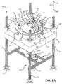
FIGS. 1A and1B illustrate perspective views of a loom system for making a composite structure, in accordance with various embodiments; -
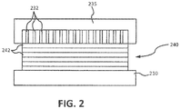
FIG. 2 illustrates an entangling head, fibrous layers, and a bedplate of a system for making a composite structure, in accordance with various embodiments; -
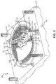
FIG. 3 illustrates a perspective view of a portion of a loom system for making a composite structure, in accordance with various embodiments; -
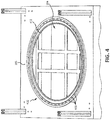
FIG. 4 illustrates a perspective view of the base of a loom system for making a composite structure, in accordance with various embodiments; and -
FIG. 5 illustrates a method for making a composite structure, in accordance with various embodiments. - All ranges may include the upper and lower values, and all ranges and ratio limits disclosed herein may be combined. It is to be understood that unless specifically stated otherwise, references to "a," "an," and/or "the" may include one or more than one and that reference to an item in the singular may also include the item in the plural.
- The detailed description of various embodiments herein makes reference to the accompanying drawings, which show various embodiments by way of illustration. While these various embodiments are described in sufficient detail to enable those skilled in the art to practice the disclosure, it should be understood that other embodiments may be realized and that logical, chemical, and mechanical changes may be made without departing from the scope of the disclosure. Thus, the detailed description herein is presented for purposes of illustration only and not of limitation. For example, the steps recited in any of the method or process descriptions may be executed in any order and are not necessarily limited to the order presented. Furthermore, any reference to singular includes plural embodiments, and any reference to more than one component or step may include a singular embodiment or step. Also, any reference to attached, fixed, connected, or the like may include permanent, removable, temporary, partial, full, and/or any other possible attachment option. Additionally, any reference to without contact (or similar phrases) may also include reduced contact or minimal contact.
- Finally, though the various embodiments discussed herein may be carried out in the context of an aircraft, it should be understood that systems and methods disclosed herein may be incorporated into anything needing a brake or having a wheel, or into any vehicle such as, for example, an aircraft, a train, a bus, an automobile and the like.
- C/C material for use in aircraft braking systems is generally formed by utilizing continuous oxidized polyacrylonitrile (PAN) fibers, referred to as "OPF" fibers. Such OPF fibers are the precursors of carbonized PAN fibers. C/C brake disks are also made using carbon fiber/phenolic prepregs and densified by either multiple infiltration/pyrolysis cycles or by chemical vapor infiltration (CVI). Thus, while some embodiments herein are discussed with reference to OPF, C/C brake disks may also be made by starting with carbon fiber as opposed to OPF. C/C disks manufactured using carbon fibers may comprise woven carbon fiber fabrics in a phenolic resin matrix which is the pyrolyzed to convert the matrix to carbon char. The fibers may be used to fabricate a preform shape using an entanglement process, for example, as discussed further herein with reference to various embodiments that use fluids such as air to orientate and/or entangle the fibers and/or fiber layer(s).
- In various embodiments, fibers are layered in a selected orientation into a fibrous preform of a selected geometry. Two or more layers of fibers may be layered onto a support and are then entangled together simultaneously or in a series of entangling steps. This process interconnects the horizontal fibers with a third direction (also called the z-direction). The fibers extending into the third direction are also called z-fibers. This entangling process may involve directing jets of air into the fibrous layers to displace a portion of the horizontal fibers in the z-direction. Thus, a fibrous preform may be produced using air entanglement by first combining or stacking multiple fibrous layers then entangling the fibrous layers using air entanglement to produce a multi-dimensional fabric including z-fibers.
- As used herein, "loom" may refer to any device for creating textiles, such the loom systems discussed herein. "Fibrous preform" may be a preform comprising carbon fibers and/or OPF, or any other suitable material, which may be densified into a C/C structure for use in braking systems, as described herein.
- According to various embodiments, with reference to
FIGS. 1A and1B , a loomsystem 100 for making a fibrous preform may comprise abedplate 110, upon whichfibrous material 126 may be layered.Bedplate 110 may be annular in order to produce net shape fibrous preforms, such as net shape fibrous preforms for brakes. A "net shape" preform indicates that the initial production of the item is very close to the final (net) shape. Therefore, such an annular bedplate may be advantageously utilized to form a near net shape air entangled fibrous preform with reduced waste. - In various embodiments,
bedplate 110 may be stationary or movable. Stationary bedplates (not shown) may be smooth bedplates, such that the other components ofloom system 100 may rotate around, and with respect to, the stationary bedplate to facilitate layering and/or entanglingfibrous material 126. Movable bedplates (such asbedplate 110 inFIGS. 1A and1B ) may be rotatable bedplates that comprise a surface that generates friction between the bedplate andfibrous material 126 such that the bedplates move and/or entrainfibrous material 126 to facilitate layering and/or entanglingfibrous material 126. As depicted inFIGS. 1A and1B ,bedplate 110 may be moveable and configured to rotate about axis ofrotation 102. With momentary additional reference toFIG. 4 ,bedplate housing 410 ofbase 105, upon which bedplate 110 rests and/or is coupled, comprisesbearings 403, which are configured to allow the rotation ofbedplate 110 relative tobase 105, which remains stationary. - With continued reference to
FIGS. 1A and1B , the positions of components of a loom system, such as loomsystem 100, relative to one another may be described alongaxis 265, which is parallel to axis ofrotation 102. Components more toward the "top" ofloom system 100, i.e., "above" other components, may be further indirection 266. Components more toward the "bottom" ofloom system 100, i.e., "below" other components, may be further indirection 267. - In various embodiments,
bedplate 110 may compriseapertures 111 configured to allow circulation of jets of air throughbedplate 110 during the entanglement of layers offibrous material 126.Bobbin 120 may be coupled tobase 105 and located abovebedplate 110. The length ofbobbin 120 may span a length ofbedplate 110 between aninner diameter 112 and anouter diameter 113 ofbedplate 110.Bobbin 120 may be abovebedplate 110 and coupled between aninner bobbin support 124 and anouter bobbin support 122.Inner bobbin support 124 andouter bobbin support 122 may be coupled tobase 105 and protrude substantially perpendicular to the plane defined by an upper surface ofbase 105.Bobbin 120 may be conical, with an outer diameter portion ofbobbin 120, proximate toouter diameter 113, being larger than an inner diameter portion ofbobbin 120, proximate toinner diameter 112.Bobbin 120 may be configured to storefibrous material 126 rolled aboutbobbin 120. In operation,bobbin 120 may unrollfibrous material 126 ontobedplate 110. Asbedplate 110 rotates, layers offibrous material 126 may be stacked on top of one another with each revolution ofbedplate 110.Fibrous material 126 may be comprised of carbon fiber, OPF, or any other suitable fibrous material. - In various embodiments, loom
system 100 may comprise anair entangling module 130.Air entangling module 130 may comprise anair entangling head 135, aninner support 131, and anouter support 132.Air entangling head 135 may span the length ofbedplate 110 betweeninner diameter 112 andouter diameter 113.Air entangling head 135 may be supported byouter support 132 proximate toouter diameter 113 andinner support 131 proximate toinner diameter 112.Inner support 131 andouter support 132 may be coupled tobase 105 and protrude substantially perpendicular to the plane defined by the upper surface ofbase 105. In various embodiments, anouter diameter portion 136 ofair entangling head 135 proximate toouter diameter 113 may have a larger width than aninner diameter portion 137 ofair entangling head 135 proximate toinner diameter 112.Air entangling head 135 may be suspended abovebedplate 110 and/or the layers offibrous material 126 that have accumulated with rotations ofbedplate 110 about axis ofrotation 102. - With combined reference to
FIGS. 1A ,1B , and2 , in various embodiments,air entangling head inner support 131 andouter support 132, i.e.,air entangling head 135 may have freedom of motion along the heights ofinner support 131 andouter support 132, such thatair entangling head stack 240 offibrous layers 242.Stack 240 offibrous layers 242 may be disposed onbaseplate 210, similar tobedplate 110 inFIGS. 1A and1B . In various embodiments,air entangling head 135 may be suspended above the top ofstack 240 offibrous layers 242, and may come in contact withfibrous layers 242 when lowered from a suspended position. - In various embodiments, in response to
fibrous material 126 reaching anentangling zone 139 located underair entangling head 135 during rotation ofbedplate 110,air entangling head 135 may be in contact with, or come into contact with, the top ofstack 240 offibrous layers 242. In response,air entangling head 135 may apply jets of air tofibrous layers 242 to create z-fibers betweenfibrous layers 242 in a direction perpendicular tofibrous layers 242 depicted inFIG. 2 . Jets of air may be applied to stack 240 through air-jet holes 232 inair entangling head 235. Compressed air may be accelerated to high velocity and expelled through air-jet holes 232 to entanglefibrous layers 242 by creating z-fibers.Air entangling head 235 may comprise any number of air-jet holes 232 and may comprise air-jet holes 232 of various sizes and arrangements. Air entanglement offibrous layers 242 may be controlled by the size of the air-jet holes 232 ofair entangling head 235, the air pressure of the jets of air, the orientation of air-jet holes 232 relative tofibrous layers 242, and/or by other mechanisms. -
FIGS. 1A and1B , in accordance with various embodiments, depictair entangling head 135 extending above only a portion of thebedplate 110, and entanglingzone 139 being on a portion ofbedplate 110 underair entangling head 135. In various embodiments,air entangling head 135 may comprise an annular shape aligned over the entire area, or a substantial portion, ofbedplate 110. In various embodiments comprising an annular air entangling head, the entire annulus, or a substantial portion, of the preform is air entangled simultaneously. Thus, fibrous layers (FIG. 2 ) do not pass through entanglingzone 139 as depicted inFIGS. 1A and1B , but rather, the entire annulus, or a substantial portion of the annulus, is entangled simultaneously, causing the entire area ofbedplate 110 to be an entangling zone. - In various embodiments, with additional reference to
FIG. 3 , an air entangling module, such asair entangling module 330, may comprise one or more rollers, such asfirst roller 336 and/orsecond roller 337. Elements with the like element numbering between figures are intended to be the same and will not be repeated for the sake of clarity. One or more rollers in a loom system, such as loomsystem 300, may be located anywhere alongbedplate 310, and may be configured to flatten or hold downfibrous material 126 as it is disposed ontobedplate 310. Additionally, the rollers may be configured to drivefibrous material 126 through entanglingzone 139. Rollers may span a length ofbedplate 310 between aninner diameter 312 and anouter diameter 313 ofbedplate 310. - As depicted in
FIG. 3 , in various embodiments,first roller 336 and/orsecond roller 337 may be coupled toair entangling head 135. In various embodiments, a roller, such asfirst roller 336, may be coupled to aproximal side 138 ofair entangling head 135,proximal side 138 being more proximate to where fibrous layers 242 (FIG.2 ) offibrous material 126 are disposed than a distal side ofair entangling head 135 oppositeproximal side 138. In various embodiments, a roller, such assecond roller 337 may be coupled toair entangling head 135 on the distal side.First roller 336 and/orsecond roller 337 may be conical, such that a portion offirst roller 336 and/orsecond roller 337 proximate toouter diameter 313 may be larger than a portion offirst roller 336 and/orsecond roller 337 proximate toinner diameter 312. - In operation, with combined reference to
FIGS. 2 and3 ,bedplate 310 may rotate about axis of rotation 102 (depicted inFIGS. 1A and1B ). Asfibrous layers 242 offibrous material 126 are disposed onbedplate 310, which is coupled tobase 305,fibrous material 126 offibrous layers 242 will reach entanglingzone 139.Air entangling head 135 may be floating such thatair entangling head 135 rests on the topfibrous layer 242 offibrous material 126. In various embodiments, withfirst roller 336 coupled to the proximal side ofair entangling head 135,fibrous material 126 will be flattened or held down byfirst roller 336 prior toair entangling head 135 applying jets of air tofibrous material 126 to entanglefibrous layers 242. In various embodiments, withsecond roller 337 coupled to the distal side ofair entangling head 135,fibrous material 126 will be flattened or held down bysecond roller 337 afterair entangling head 135 applies jets of air tofibrous material 126 to entanglefibrous layers 242. Compressed air may be supplied to air entanglinghead 135 throughnozzle 338 orair entangling module 330. - In various embodiments, to apply more or less of a load by
air entangling head 135 androllers fibrous layers 242 offibrous material 126, springs 339 may be coupled toinner support 131 and/orouter support 132, onespring 339 being an inner diameter spring and the other being an outer diameter spring. To apply a reduced load byair entangling head 135 androllers fibrous layers 242, springs 339 may be extension springs. To apply an increased load byair entangling head 135 androllers fibrous layers 242, springs 339 may be compression springs. The load applied byair entangling head 135 androllers fibrous layers 242 may be adjusted in any other suitable way, such as adjusting the weight ofrollers air entangling head 135. - In various embodiments, with further reference to
FIGS. 2 and3 , a firstfibrous layer 242 ofstack 240 may be disposed onbedplate 310. The firstfibrous layer 242 may be coupled tobedplate 310 in any suitable manner. In various embodiments,bedplate 310 may comprise aninner clamp 315 atinner diameter 312 and anouter clamp 316 atouter diameter 313.Inner clamp 315 may clamp an inner diameter portion of the firstfibrous layer 242 to bedplate 310 andouter clamp 316 may clamp an outer diameter portion of the firstfibrous layer 242 tobedplate 310. The firstfibrous layer 242 may be clamped down so thatfibrous layers 242 subsequently disposed on top of the firstfibrous layer 242 may be entangled to the firstfibrous layer 242 by jets of air fromair entangling head 135 at entanglingzone 139. - With reference again to
FIGS. 1A ,1B , and2 , in various embodiments,base 105 may comprise anupper base 106 and alower base 107. In various embodiments, avacuum chamber 104 may be enclosed inbase 105, betweenupper base 106 andlower base 107.Lower base 107 may be configured to separate fromupper base 106 to exposevacuum chamber 104. In various embodiments,apertures 111 inbedplate 110 may provide fluid communication betweenfibrous layers 242 andvacuum chamber 104, such that stray fibers breaking fromfibrous material 126 caused by jets of air during entangling may be caught invacuum chamber 104. Stray fibers invacuum chamber 104 may be vacuumed out throughvacuum aperture 108, or otherwise removed fromvacuum chamber 104.Vacuum chamber 104 is also depicted inFIG. 4 through a bedplate void defined bybase rim 411.Vacuum chamber 104 is visible through the bedplate void in response tobedplate 110 being decoupled frombase 105. - In various embodiments, an
upper vacuum head 127 may be coupled to an upper surface ofbase 105 proximate to bedplate 110 and entanglingzone 139.Upper vacuum head 127 may be coupled to a vacuum source and configured to collect stray fibers breaking fromfibrous material 126 caused by jets of air during entangling.Upper vacuum head 127 may be coupled at any suitable location onbase 105. In various embodiments, a housing may be coupled tobase 105, enclosing thearea comprising bedplate 110,bobbin 120, andair entangling module 130. The enclosed area may also be configured to aid in the vacuum collection of stray fibers throughupper vacuum head 127. - In various embodiments,
base 105 may comprise anemergency shutoff 109 configured to stop operation ofloom system 100 in response to engagingemergency shutoff 109.Emergency shutoff 109 may be disposed anywhere onbase 105. - In various embodiments,
base 105 may be coupled to asupport structure 170 configured to supportbase 105 and the components coupled tobase 105 in a desired spatial location. As depicted inFIGS. 1A and1B ,support structure 170 may compriselegs 172 which couple tobase 105.Lower base 107 and/orupper base 106 may be configured to move alonglegs 172 to exposevacuum chamber 104. In various embodiments,brackets 174 may couplelegs 172 to a floor or foundation.Legs 172 may be coupled to a floor or foundation in any suitable manner.Base 105 may be coupled to supportstructure 170 and/orlegs 172 bybrackets 173 or in any other suitable manner. - In various embodiments,
support structure 170 may comprise alower support 175 configured to support amotor 160 ofloom system 100.Motor 160 may be coupled to supportstructure 170 atlower support 175, or at any other suitable location onsupport structure 170.Motor 160 may be configured to drive adrive shaft 134, which may take place by rotating one or more gears 162. Driveshaft 134 may be disposed throughvacuum chamber 104 and couple to bedplate 110, to rotatebedplate 110 during operation ofmotor 160.Motor 160 may be separated by a distance frombedplate 110 and/orbase 105 in order to avoid stray fibers resulting from air entangling from contaminatingmotor 160. - With reference to
FIG. 5 , amethod 500 for making a fibrous preform is depicted, in accordance with various embodiments. With combined reference toFIGS. 1B ,2 , and5 , in various embodiments,method 500 may comprise rotating bedplate 110 (step 502) about axis ofrotation 102.Bedplate 110 may be rotated bymotor 160, which drivesdrive shaft 134 coupled tobedplate 110. A firstfibrous layer 242 may be disposed onto bedplate 110 (step 504) bybobbin 120, or in any other suitable manner. Step 504 may take place before, during, or afterstep 502. The firstfibrous layer 242 may be coupled tobedplate 110 by inner andouter clamps bobbin 120 or another suitable manner.Fibrous layers 242 may be disposed on bedplate 110 (step 506) during thebedplate 110 rotation (step 502). - In various embodiments,
air entangling head 135 may rest on top of fibrous layers 242 (step 508) asfibrous layers 242 are being disposed ontobedplate 110 intostack 240.Air entangling head 135 may float along the heights ofinner support 131 andouter support 132 such thatair entangling head stack 240 offibrous layers 242.Air entangling head 135 may apply a jet of air to fibrous layers 242 (step 510) to entanglefibrous layers 242 together by forming z-fibers, in response to a portion of un-entangledfibrous material 126 reachingentangling zone 139.Air entangling head 135 may apply a jet of air in response to eachfibrous layer 242 being added to stack 240, or in response to any suitable number offibrous layers 242 being added to stack 240. As a result of the air entangling offibrous layers 242, stray fibers breaking fromfibrous material 126 may pass throughapertures 111 inbedplate 110, and accumulate invacuum chamber 104. Therefore, stray fibers may be collected from vacuum chamber 104 (step 512) by vacuum suction throughvacuum aperture 108 or by any other suitable method. - In various embodiments, with combined reference to
FIGS. 2 ,3 , and5 ,fibrous layers 242 may be flattened (step 514) by a roller, such asfirst roller 336 and/orsecond roller 337, before and/or after entanglingzone 139. In various embodiments,fibrous layers 242 may be flattened beforeair entangling head 135 applies a jet of air tofibrous layers 242 byfirst roller 336 coupled to the proximal side to air entanglinghead 135. In various embodiments,fibrous layers 242 may be flattened afterair entangling head 135 applies a jet of air tofibrous layers 242 bysecond roller 337 coupled to the distal side to air entanglinghead 135. - In various embodiments,
steps 506 through 514 may occur whilebedplate 110 is rotating (i.e., during step 502). In various embodiments,steps fibrous layers 242 reaches a desired number of layers and/or a desired thickness. With reference toFIGS. 1A ,3 , and5 , upon making a fibrous preform comprising the desired number of fibrous layers or the desired thickness, the fibrous preform may be removed from loom system 100 (step 516). The fibrous preform may be removed by movingair entangling head 135 such that it does not block movement of the fibrous preform onbedplate 110 from being lifted in a direction parallel to axis ofrotation 102. In various embodiments,air entangling head 135 may be configured to decouple frominner support 131 and/orouter support 132. In various embodiments,air entangling head 135 may decouple frominner support 131 and rotate aboutouter support 132 so thatair entangling head 135 is no longer disposed betweeninner diameter 112 andouter diameter 113 ofbedplate 110.Bobbin 120 may be similarly removed frominner bobbin support 124 and/orouter bobbin support 122, and/or rotated aboutouter bobbin support 122. The fibrous preform may then be removed frombedplate 110 and loomsystem 100 by being lifted frombedplate 110. - Benefits and other advantages have been described herein with regard to specific embodiments. Furthermore, the connecting lines shown in the various figures contained herein are intended to represent exemplary functional relationships and/or physical couplings between the various elements. It should be noted that many alternative or additional functional relationships or physical connections may be present in a practical system. However, the benefits, advantages, solutions to problems, and any elements that may cause any benefit, advantage, or solution to occur or become more pronounced are not to be construed as critical, required, or essential features or elements of the disclosure. The scope of the disclosure is accordingly to be limited by nothing other than the appended claims, in which reference to an element in the singular is not intended to mean "one and only one" unless explicitly so stated, but rather "one or more." Moreover, where a phrase similar to "at least one of A, B, or C" is used in the claims, it is intended that the phrase be interpreted to mean that A alone may be present in an embodiment, B alone may be present in an embodiment, C alone may be present in an embodiment, or that any combination of the elements A, B and C may be present in a single embodiment; for example, A and B, A and C, B and C, or A and B and C.
- Systems, methods and apparatus are provided herein. In the detailed description herein, references to "one embodiment," "an embodiment," "an example embodiment," etc., indicate that the embodiment described may include a particular feature, structure, or characteristic, but every embodiment may not necessarily include the particular feature, structure, or characteristic. Moreover, such phrases are not necessarily referring to the same embodiment. Further, when a particular feature, structure, or characteristic is described in connection with an embodiment, it is submitted that it is within the knowledge of one skilled in the art to affect such feature, structure, or characteristic in connection with other embodiments whether or not explicitly described. After reading the description, it will be apparent to one skilled in the relevant art(s) how to implement the disclosure in alternative embodiments.
Claims (15)
- A loom system for making a fibrous preform, comprising:a base (105);a bedplate (110) coupled to the base, wherein the bedplate is configured to rotate about an axis of rotation (102); andan air entangling module (130) coupled to the base, the air entangling module comprising an air entangling head (135) coupled to an outer support (132) and an inner support (131), wherein the air entangling head is configured to apply a jet of air toward the bedplate at an entangling zone, wherein the air entangling head has freedom of motion along the outer support and the inner support, the air entangling head being configured to rest on top of a fibrous layer.
- The loom system of claim 1, wherein the bedplate comprises an aperture (111) configured to allow circulation of the jet of air from the air entangling head through the bedplate.
- The loom system of claim 2, further comprising a vacuum chamber (104) comprised within the base and disposed below the bedplate.
- The loom system of any preceding claim, wherein the air entangling module further comprises an inner diameter spring (339) coupled to the inner support and an outer diameter spring (339) coupled to the outer support, wherein the inner diameter spring and the outer diameter spring are configured to at least one of increase or decrease a load applied to the fibrous layer by the air entangling head.
- The loom system of any preceding claim, wherein the base is coupled to a support structure (170) configured to support the base and a motor, and separate the base from the motor.
- The loom system of claim 5, wherein the motor is configured to rotate a drive shaft (134) coupled to the motor (160), wherein the drive shaft is coupled to the bedplate and is configured to rotate the bedplate.
- A loom system for making a fibrous preform, comprising:a base (105);a bedplate (110) coupled to the base, wherein the bedplate is configured to rotate about an axis of rotation (102);an air entangling module (130) coupled to the base, the air entangling module comprising an air entangling head (135) configured to apply a jet of air toward the bedplate an entangling zone; anda vacuum chamber (104) within the base and disposed below the bedplate.
- The loom system of any preceding claim, further comprising a bobbin (120) configured to dispose a fibrous layer onto the bedplate.
- The loom system of any preceding claim, further comprising a roller (336, 337) coupled to at least one of a proximal side or a distal side of the air entangling head configured to flatten a fibrous layer proximate to the entangling zone.
- The loom system of claim 9, wherein the air entangling head is coupled to an inner support (131) and an outer support (132), wherein the air entangling head has freedom of motion along the inner support and the outer support.
- The loom system of any preceding claim, further comprising an upper vacuum head disposed proximate to the entangling zone, wherein the upper vacuum head is configured to collect stray fibers from an upper surface of the base.
- A method for making a fibrous preform, comprising:rotating a bedplate of a loom system for making the fibrous preform about an axis of rotation;disposing a plurality of fibrous layers onto a first fibrous layer during the rotating the bedplate;resting an air entangling head of an air entangling module on top of the plurality of fibrous layers; andapplying a jet of air to the plurality of fibrous layers from the air entangling head at an entangling zone of the loom system.
- The method of claim 12, further comprising disposing the first fibrous layer onto the bedplate by clamping an inner diameter portion and an outer diameter portion of the first fibrous layer to the bedplate.
- The method of claim 12, further comprising collecting stray fibers from a vacuum chamber disposed below the bedplate.
- The method of claim 12, further comprising flattening by a roller coupled to the air entangling head the plurality of fibrous layers at least one of before or after the applying the jet of air to the plurality fibrous layers.
Applications Claiming Priority (1)
| Application Number | Priority Date | Filing Date | Title |
|---|---|---|---|
| US15/245,007 US10081892B2 (en) | 2016-08-23 | 2016-08-23 | Systems and methods for air entanglement |
Publications (2)
| Publication Number | Publication Date |
|---|---|
| EP3287553A1 true EP3287553A1 (en) | 2018-02-28 |
| EP3287553B1 EP3287553B1 (en) | 2020-04-22 |
Family
ID=59858870
Family Applications (1)
| Application Number | Title | Priority Date | Filing Date |
|---|---|---|---|
| EP17187449.8A Active EP3287553B1 (en) | 2016-08-23 | 2017-08-23 | Systems and methods for air entanglement |
Country Status (2)
| Country | Link |
|---|---|
| US (1) | US10081892B2 (en) |
| EP (1) | EP3287553B1 (en) |
Families Citing this family (2)
| Publication number | Priority date | Publication date | Assignee | Title |
|---|---|---|---|---|
| US11492733B2 (en) * | 2020-02-21 | 2022-11-08 | Raytheon Technologies Corporation | Weave control grid |
| US11535962B2 (en) * | 2020-05-21 | 2022-12-27 | Raytheon Technologies Corporation | Weaving assembly and method of using |
Citations (4)
| Publication number | Priority date | Publication date | Assignee | Title |
|---|---|---|---|---|
| US3120463A (en) * | 1964-02-04 | Porous fibrous sheet material | ||
| WO1999028122A1 (en) * | 1997-12-03 | 1999-06-10 | Hills, Inc. | Nonwoven fabrics formed from ribbon-shaped fibers and method and apparatus for making the same |
| EP2955260A1 (en) * | 2014-06-09 | 2015-12-16 | Goodrich Corporation | System and method for air entanglement |
| EP3073004A1 (en) * | 2015-03-27 | 2016-09-28 | Goodrich Corporation | System and method for multiple surface air jet needling |
Family Cites Families (25)
| Publication number | Priority date | Publication date | Assignee | Title |
|---|---|---|---|---|
| US2862251A (en) | 1955-04-12 | 1958-12-02 | Chicopee Mfg Corp | Method of and apparatus for producing nonwoven product |
| US3110151A (en) | 1961-05-26 | 1963-11-12 | Du Pont | Process for producing compact interlaced yarn |
| BR6456568D0 (en) * | 1963-02-23 | 1973-12-27 | Honshu Paper Co Ltd | PROCESS FOR THE MANUFACTURE OF PERFECTED FLUID ABSORBING MATERIAL AS WELL AS THE RESPECTIVE ABSORBENT MATERIAL |
| US3391048A (en) * | 1964-01-10 | 1968-07-02 | Eastman Kodak Co | Entangled nonwoven web product from parallel laid filamentary tows |
| US3422510A (en) | 1964-12-30 | 1969-01-21 | Celanese Corp | Apparatus and method for producing a non-woven fabric |
| US3458905A (en) * | 1966-07-05 | 1969-08-05 | Du Pont | Apparatus for entangling fibers |
| US3485706A (en) * | 1968-01-18 | 1969-12-23 | Du Pont | Textile-like patterned nonwoven fabrics and their production |
| US3688355A (en) | 1969-05-13 | 1972-09-05 | Kuraray Co | Method and apparatus for preparing non-woven fibrous materials |
| US3747161A (en) | 1971-08-20 | 1973-07-24 | Johnson & Johnson | Method for producing a rearranged fabric having improved cross-strength |
| DE3238084A1 (en) | 1982-10-14 | 1984-04-26 | Mathias 4815 Schloss Holte Mitter | DEVICE FOR EVENLY DELIVERING, DISTRIBUTING AND APPLYING A FOAMED FLEET OF APPLICATION TO A PREFERRED TEXTILE TRACK OR THE LIKE. |
| IT1233086B (en) * | 1989-05-31 | 1992-03-14 | Claudio Governale | Consolidating loose fibrous nonwoven structures into web |
| US5238644A (en) | 1990-07-26 | 1993-08-24 | Johnson & Johnson Inc. | Low fluid pressure dual-sided fiber entanglement method, apparatus and resulting product |
| FR2741634B1 (en) | 1995-11-27 | 1998-04-17 | Europ Propulsion | PROCESS FOR THE REALIZATION OF FIBROUS PREFORMS INTENDED FOR THE MANUFACTURE OF ANNULAR PIECES IN COMPOSITE MATERIAL |
| US6052983A (en) | 1998-06-24 | 2000-04-25 | Belmont Textile Machinery Co., Inc. | Fluid-jet twist-inserting apparatus and method |
| JP3620021B2 (en) | 2001-01-12 | 2005-02-16 | 中部電力株式会社 | High-speed rotating body for power storage flywheel |
| FR2824086B1 (en) | 2001-04-30 | 2003-08-01 | Messier Bugatti | SMOOTH TABLE CIRCULAR NEEDLE MACHINE |
| FR2824084B1 (en) | 2001-04-30 | 2003-08-01 | Messier Bugatti | NEEDLE FEEDER BY CONTINUOUS SPIRAL BAND |
| FR2824085B1 (en) | 2001-04-30 | 2003-08-01 | Messier Bugatti | CIRCULAR NEEDLE MACHINE PROVIDED WITH AN AUTOMATIC PREFORM DEVICE |
| JP4439854B2 (en) * | 2002-10-08 | 2010-03-24 | 三菱レイヨン・エンジニアリング株式会社 | Non-woven fabric manufacturing method using pressurized steam jet nozzle |
| EP1560966B1 (en) | 2002-11-12 | 2013-05-29 | The Procter & Gamble Company | Process and apparatus for preparing a molded, textured, spunlaced, nonwoven web |
| FR2869330B1 (en) | 2004-04-23 | 2006-07-21 | Messier Bugatti Sa | PROCESS FOR PRODUCING TWO-DIMENSIONAL HELICOIDAL FIBROUS TABLET |
| GB0514141D0 (en) | 2005-07-09 | 2005-08-17 | P G Lawton Ind Services Ltd | Production of shaped filamentary structures |
| DE102009007669A1 (en) | 2009-02-05 | 2010-08-12 | Fleissner Gmbh | Method and device for producing cotton wool products |
| FR2954358B1 (en) | 2009-12-23 | 2012-01-13 | Messier Bugatti | CIRCULAR CLAMPING TABLE FOR TEXTILE STRUCTURE FORMED FROM ANNIBLE FIBROUS PREFORM |
| US9309613B1 (en) | 2014-11-03 | 2016-04-12 | Goodrich Corporation | System and method to fabricate helical fabric |
-
2016
- 2016-08-23 US US15/245,007 patent/US10081892B2/en active Active
-
2017
- 2017-08-23 EP EP17187449.8A patent/EP3287553B1/en active Active
Patent Citations (4)
| Publication number | Priority date | Publication date | Assignee | Title |
|---|---|---|---|---|
| US3120463A (en) * | 1964-02-04 | Porous fibrous sheet material | ||
| WO1999028122A1 (en) * | 1997-12-03 | 1999-06-10 | Hills, Inc. | Nonwoven fabrics formed from ribbon-shaped fibers and method and apparatus for making the same |
| EP2955260A1 (en) * | 2014-06-09 | 2015-12-16 | Goodrich Corporation | System and method for air entanglement |
| EP3073004A1 (en) * | 2015-03-27 | 2016-09-28 | Goodrich Corporation | System and method for multiple surface air jet needling |
Also Published As
| Publication number | Publication date |
|---|---|
| US20180057979A1 (en) | 2018-03-01 |
| EP3287553B1 (en) | 2020-04-22 |
| US10081892B2 (en) | 2018-09-25 |
Similar Documents
| Publication | Publication Date | Title |
|---|---|---|
| US9783917B2 (en) | System and method for air entanglement | |
| US4790052A (en) | Process for manufacturing homogeneously needled three-dimensional structures of fibrous material | |
| US9546438B2 (en) | Low z high performance carbon composite materials | |
| JP3235065B2 (en) | Manufacture of shaped filament structure | |
| JP7610900B2 (en) | Preform molding method and preform molding device that integrates knitting and needling | |
| US9932696B2 (en) | System and method for transport of fibers to/from a circular needle-punching loom | |
| CN1212034A (en) | Method for producing a fiber preform for producing rings of synthetic material | |
| EP3287553B1 (en) | Systems and methods for air entanglement | |
| EP3257987B1 (en) | Systems and methods for forming a composite structure | |
| EP3805592B1 (en) | Composite fiber preform for disc brakes | |
| EP3804967B1 (en) | Method for manufacturing composite fiber preform for disc brakes | |
| EP3312326B1 (en) | System and method for multiple surface air jet needling | |
| JPH08312699A (en) | Near-net-shaped fibrous structure and manufacture thereof | |
| US12344492B2 (en) | Individual zone tension control | |
| EP3176460B1 (en) | Methods for atmospheric single cycle carbonization | |
| US10640900B2 (en) | System and method for multiple surface water jet needling | |
| EP3015585A1 (en) | System and method for manufacturing net shape preform from textile strips |
Legal Events
| Date | Code | Title | Description |
|---|---|---|---|
| PUAI | Public reference made under article 153(3) epc to a published international application that has entered the european phase |
Free format text: ORIGINAL CODE: 0009012 |
|
| STAA | Information on the status of an ep patent application or granted ep patent |
Free format text: STATUS: THE APPLICATION HAS BEEN PUBLISHED |
|
| AK | Designated contracting states |
Kind code of ref document: A1 Designated state(s): AL AT BE BG CH CY CZ DE DK EE ES FI FR GB GR HR HU IE IS IT LI LT LU LV MC MK MT NL NO PL PT RO RS SE SI SK SM TR |
|
| AX | Request for extension of the european patent |
Extension state: BA ME |
|
| STAA | Information on the status of an ep patent application or granted ep patent |
Free format text: STATUS: REQUEST FOR EXAMINATION WAS MADE |
|
| 17P | Request for examination filed |
Effective date: 20180828 |
|
| RBV | Designated contracting states (corrected) |
Designated state(s): AL AT BE BG CH CY CZ DE DK EE ES FI FR GB GR HR HU IE IS IT LI LT LU LV MC MK MT NL NO PL PT RO RS SE SI SK SM TR |
|
| GRAP | Despatch of communication of intention to grant a patent |
Free format text: ORIGINAL CODE: EPIDOSNIGR1 |
|
| STAA | Information on the status of an ep patent application or granted ep patent |
Free format text: STATUS: GRANT OF PATENT IS INTENDED |
|
| INTG | Intention to grant announced |
Effective date: 20191125 |
|
| GRAS | Grant fee paid |
Free format text: ORIGINAL CODE: EPIDOSNIGR3 |
|
| GRAA | (expected) grant |
Free format text: ORIGINAL CODE: 0009210 |
|
| STAA | Information on the status of an ep patent application or granted ep patent |
Free format text: STATUS: THE PATENT HAS BEEN GRANTED |
|
| AK | Designated contracting states |
Kind code of ref document: B1 Designated state(s): AL AT BE BG CH CY CZ DE DK EE ES FI FR GB GR HR HU IE IS IT LI LT LU LV MC MK MT NL NO PL PT RO RS SE SI SK SM TR |
|
| REG | Reference to a national code |
Ref country code: CH Ref legal event code: EP |
|
| REG | Reference to a national code |
Ref country code: IE Ref legal event code: FG4D |
|
| REG | Reference to a national code |
Ref country code: DE Ref legal event code: R096 Ref document number: 602017015078 Country of ref document: DE |
|
| REG | Reference to a national code |
Ref country code: AT Ref legal event code: REF Ref document number: 1260181 Country of ref document: AT Kind code of ref document: T Effective date: 20200515 |
|
| REG | Reference to a national code |
Ref country code: LT Ref legal event code: MG4D |
|
| REG | Reference to a national code |
Ref country code: NL Ref legal event code: MP Effective date: 20200422 |
|
| PG25 | Lapsed in a contracting state [announced via postgrant information from national office to epo] |
Ref country code: FI Free format text: LAPSE BECAUSE OF FAILURE TO SUBMIT A TRANSLATION OF THE DESCRIPTION OR TO PAY THE FEE WITHIN THE PRESCRIBED TIME-LIMIT Effective date: 20200422 Ref country code: IS Free format text: LAPSE BECAUSE OF FAILURE TO SUBMIT A TRANSLATION OF THE DESCRIPTION OR TO PAY THE FEE WITHIN THE PRESCRIBED TIME-LIMIT Effective date: 20200822 Ref country code: NO Free format text: LAPSE BECAUSE OF FAILURE TO SUBMIT A TRANSLATION OF THE DESCRIPTION OR TO PAY THE FEE WITHIN THE PRESCRIBED TIME-LIMIT Effective date: 20200722 Ref country code: GR Free format text: LAPSE BECAUSE OF FAILURE TO SUBMIT A TRANSLATION OF THE DESCRIPTION OR TO PAY THE FEE WITHIN THE PRESCRIBED TIME-LIMIT Effective date: 20200723 Ref country code: LT Free format text: LAPSE BECAUSE OF FAILURE TO SUBMIT A TRANSLATION OF THE DESCRIPTION OR TO PAY THE FEE WITHIN THE PRESCRIBED TIME-LIMIT Effective date: 20200422 Ref country code: PT Free format text: LAPSE BECAUSE OF FAILURE TO SUBMIT A TRANSLATION OF THE DESCRIPTION OR TO PAY THE FEE WITHIN THE PRESCRIBED TIME-LIMIT Effective date: 20200824 Ref country code: NL Free format text: LAPSE BECAUSE OF FAILURE TO SUBMIT A TRANSLATION OF THE DESCRIPTION OR TO PAY THE FEE WITHIN THE PRESCRIBED TIME-LIMIT Effective date: 20200422 Ref country code: SE Free format text: LAPSE BECAUSE OF FAILURE TO SUBMIT A TRANSLATION OF THE DESCRIPTION OR TO PAY THE FEE WITHIN THE PRESCRIBED TIME-LIMIT Effective date: 20200422 |
|
| REG | Reference to a national code |
Ref country code: AT Ref legal event code: MK05 Ref document number: 1260181 Country of ref document: AT Kind code of ref document: T Effective date: 20200422 |
|
| PG25 | Lapsed in a contracting state [announced via postgrant information from national office to epo] |
Ref country code: HR Free format text: LAPSE BECAUSE OF FAILURE TO SUBMIT A TRANSLATION OF THE DESCRIPTION OR TO PAY THE FEE WITHIN THE PRESCRIBED TIME-LIMIT Effective date: 20200422 Ref country code: LV Free format text: LAPSE BECAUSE OF FAILURE TO SUBMIT A TRANSLATION OF THE DESCRIPTION OR TO PAY THE FEE WITHIN THE PRESCRIBED TIME-LIMIT Effective date: 20200422 Ref country code: BG Free format text: LAPSE BECAUSE OF FAILURE TO SUBMIT A TRANSLATION OF THE DESCRIPTION OR TO PAY THE FEE WITHIN THE PRESCRIBED TIME-LIMIT Effective date: 20200722 Ref country code: RS Free format text: LAPSE BECAUSE OF FAILURE TO SUBMIT A TRANSLATION OF THE DESCRIPTION OR TO PAY THE FEE WITHIN THE PRESCRIBED TIME-LIMIT Effective date: 20200422 |
|
| PG25 | Lapsed in a contracting state [announced via postgrant information from national office to epo] |
Ref country code: AL Free format text: LAPSE BECAUSE OF FAILURE TO SUBMIT A TRANSLATION OF THE DESCRIPTION OR TO PAY THE FEE WITHIN THE PRESCRIBED TIME-LIMIT Effective date: 20200422 |
|
| REG | Reference to a national code |
Ref country code: DE Ref legal event code: R097 Ref document number: 602017015078 Country of ref document: DE |
|
| PG25 | Lapsed in a contracting state [announced via postgrant information from national office to epo] |
Ref country code: ES Free format text: LAPSE BECAUSE OF FAILURE TO SUBMIT A TRANSLATION OF THE DESCRIPTION OR TO PAY THE FEE WITHIN THE PRESCRIBED TIME-LIMIT Effective date: 20200422 Ref country code: CZ Free format text: LAPSE BECAUSE OF FAILURE TO SUBMIT A TRANSLATION OF THE DESCRIPTION OR TO PAY THE FEE WITHIN THE PRESCRIBED TIME-LIMIT Effective date: 20200422 Ref country code: RO Free format text: LAPSE BECAUSE OF FAILURE TO SUBMIT A TRANSLATION OF THE DESCRIPTION OR TO PAY THE FEE WITHIN THE PRESCRIBED TIME-LIMIT Effective date: 20200422 Ref country code: EE Free format text: LAPSE BECAUSE OF FAILURE TO SUBMIT A TRANSLATION OF THE DESCRIPTION OR TO PAY THE FEE WITHIN THE PRESCRIBED TIME-LIMIT Effective date: 20200422 Ref country code: AT Free format text: LAPSE BECAUSE OF FAILURE TO SUBMIT A TRANSLATION OF THE DESCRIPTION OR TO PAY THE FEE WITHIN THE PRESCRIBED TIME-LIMIT Effective date: 20200422 Ref country code: DK Free format text: LAPSE BECAUSE OF FAILURE TO SUBMIT A TRANSLATION OF THE DESCRIPTION OR TO PAY THE FEE WITHIN THE PRESCRIBED TIME-LIMIT Effective date: 20200422 Ref country code: SM Free format text: LAPSE BECAUSE OF FAILURE TO SUBMIT A TRANSLATION OF THE DESCRIPTION OR TO PAY THE FEE WITHIN THE PRESCRIBED TIME-LIMIT Effective date: 20200422 Ref country code: IT Free format text: LAPSE BECAUSE OF FAILURE TO SUBMIT A TRANSLATION OF THE DESCRIPTION OR TO PAY THE FEE WITHIN THE PRESCRIBED TIME-LIMIT Effective date: 20200422 |
|
| PG25 | Lapsed in a contracting state [announced via postgrant information from national office to epo] |
Ref country code: SK Free format text: LAPSE BECAUSE OF FAILURE TO SUBMIT A TRANSLATION OF THE DESCRIPTION OR TO PAY THE FEE WITHIN THE PRESCRIBED TIME-LIMIT Effective date: 20200422 Ref country code: PL Free format text: LAPSE BECAUSE OF FAILURE TO SUBMIT A TRANSLATION OF THE DESCRIPTION OR TO PAY THE FEE WITHIN THE PRESCRIBED TIME-LIMIT Effective date: 20200422 |
|
| PLBE | No opposition filed within time limit |
Free format text: ORIGINAL CODE: 0009261 |
|
| STAA | Information on the status of an ep patent application or granted ep patent |
Free format text: STATUS: NO OPPOSITION FILED WITHIN TIME LIMIT |
|
| REG | Reference to a national code |
Ref country code: DE Ref legal event code: R119 Ref document number: 602017015078 Country of ref document: DE |
|
| 26N | No opposition filed |
Effective date: 20210125 |
|
| PG25 | Lapsed in a contracting state [announced via postgrant information from national office to epo] |
Ref country code: MC Free format text: LAPSE BECAUSE OF FAILURE TO SUBMIT A TRANSLATION OF THE DESCRIPTION OR TO PAY THE FEE WITHIN THE PRESCRIBED TIME-LIMIT Effective date: 20200422 |
|
| REG | Reference to a national code |
Ref country code: CH Ref legal event code: PL |
|
| PG25 | Lapsed in a contracting state [announced via postgrant information from national office to epo] |
Ref country code: LI Free format text: LAPSE BECAUSE OF NON-PAYMENT OF DUE FEES Effective date: 20200831 Ref country code: LU Free format text: LAPSE BECAUSE OF NON-PAYMENT OF DUE FEES Effective date: 20200823 Ref country code: CH Free format text: LAPSE BECAUSE OF NON-PAYMENT OF DUE FEES Effective date: 20200831 |
|
| REG | Reference to a national code |
Ref country code: BE Ref legal event code: MM Effective date: 20200831 |
|
| PG25 | Lapsed in a contracting state [announced via postgrant information from national office to epo] |
Ref country code: SI Free format text: LAPSE BECAUSE OF FAILURE TO SUBMIT A TRANSLATION OF THE DESCRIPTION OR TO PAY THE FEE WITHIN THE PRESCRIBED TIME-LIMIT Effective date: 20200422 |
|
| PG25 | Lapsed in a contracting state [announced via postgrant information from national office to epo] |
Ref country code: DE Free format text: LAPSE BECAUSE OF NON-PAYMENT OF DUE FEES Effective date: 20210302 |
|
| PG25 | Lapsed in a contracting state [announced via postgrant information from national office to epo] |
Ref country code: IE Free format text: LAPSE BECAUSE OF NON-PAYMENT OF DUE FEES Effective date: 20200823 Ref country code: BE Free format text: LAPSE BECAUSE OF NON-PAYMENT OF DUE FEES Effective date: 20200831 |
|
| PG25 | Lapsed in a contracting state [announced via postgrant information from national office to epo] |
Ref country code: TR Free format text: LAPSE BECAUSE OF FAILURE TO SUBMIT A TRANSLATION OF THE DESCRIPTION OR TO PAY THE FEE WITHIN THE PRESCRIBED TIME-LIMIT Effective date: 20200422 Ref country code: MT Free format text: LAPSE BECAUSE OF FAILURE TO SUBMIT A TRANSLATION OF THE DESCRIPTION OR TO PAY THE FEE WITHIN THE PRESCRIBED TIME-LIMIT Effective date: 20200422 Ref country code: CY Free format text: LAPSE BECAUSE OF FAILURE TO SUBMIT A TRANSLATION OF THE DESCRIPTION OR TO PAY THE FEE WITHIN THE PRESCRIBED TIME-LIMIT Effective date: 20200422 |
|
| PG25 | Lapsed in a contracting state [announced via postgrant information from national office to epo] |
Ref country code: MK Free format text: LAPSE BECAUSE OF FAILURE TO SUBMIT A TRANSLATION OF THE DESCRIPTION OR TO PAY THE FEE WITHIN THE PRESCRIBED TIME-LIMIT Effective date: 20200422 |
|
| P01 | Opt-out of the competence of the unified patent court (upc) registered |
Effective date: 20230522 |
|
| PGFP | Annual fee paid to national office [announced via postgrant information from national office to epo] |
Ref country code: GB Payment date: 20250724 Year of fee payment: 9 |
|
| PGFP | Annual fee paid to national office [announced via postgrant information from national office to epo] |
Ref country code: FR Payment date: 20250725 Year of fee payment: 9 |