EP3287359A1 - Drain mast of an aircraft - Google Patents
Drain mast of an aircraft Download PDFInfo
- Publication number
- EP3287359A1 EP3287359A1 EP16382400.6A EP16382400A EP3287359A1 EP 3287359 A1 EP3287359 A1 EP 3287359A1 EP 16382400 A EP16382400 A EP 16382400A EP 3287359 A1 EP3287359 A1 EP 3287359A1
- Authority
- EP
- European Patent Office
- Prior art keywords
- pipe
- drain mast
- tube
- aircraft
- duct
- Prior art date
- Legal status (The legal status is an assumption and is not a legal conclusion. Google has not performed a legal analysis and makes no representation as to the accuracy of the status listed.)
- Granted
Links
Images


Classifications
-
- B—PERFORMING OPERATIONS; TRANSPORTING
- B64—AIRCRAFT; AVIATION; COSMONAUTICS
- B64D—EQUIPMENT FOR FITTING IN OR TO AIRCRAFT; FLIGHT SUITS; PARACHUTES; ARRANGEMENT OR MOUNTING OF POWER PLANTS OR PROPULSION TRANSMISSIONS IN AIRCRAFT
- B64D33/00—Arrangement in aircraft of power plant parts or auxiliaries not otherwise provided for
-
- B—PERFORMING OPERATIONS; TRANSPORTING
- B64—AIRCRAFT; AVIATION; COSMONAUTICS
- B64C—AEROPLANES; HELICOPTERS
- B64C1/00—Fuselages; Constructional features common to fuselages, wings, stabilising surfaces or the like
- B64C1/14—Windows; Doors; Hatch covers or access panels; Surrounding frame structures; Canopies; Windscreens accessories therefor, e.g. pressure sensors, water deflectors, hinges, seals, handles, latches, windscreen wipers
- B64C1/1407—Doors; surrounding frames
- B64C1/1453—Drain masts
-
- B—PERFORMING OPERATIONS; TRANSPORTING
- B64—AIRCRAFT; AVIATION; COSMONAUTICS
- B64D—EQUIPMENT FOR FITTING IN OR TO AIRCRAFT; FLIGHT SUITS; PARACHUTES; ARRANGEMENT OR MOUNTING OF POWER PLANTS OR PROPULSION TRANSMISSIONS IN AIRCRAFT
- B64D41/00—Power installations for auxiliary purposes
Definitions
- the present invention relates to a drain mast of a compartment, receptacle or piping of an aircraft intended to drain a fluid, more particularly, to the drain mast of the compartment of an auxiliary power unit (APU) of an aircraft.
- APU auxiliary power unit
- auxiliary power unit APU
- Masts are supposed to release both small portions of fluid and large fluid leakages being this last case the sizing case.
- a drain mast is intended to evacuate fluid as a result of a failure, malfunction or similar. Being this purpose the first criteria to satisfy for certification, it is usually accompanied with the requirement, in case of flammable fluids, of avoiding that the drained liquid impinges onto an external hot area of the aircraft that could start a fire.
- the mast should avoid the fluid from attaching to the skin of the fuselage.
- the fluid oil in this case, creates stains causing inspections, complaints or cleaning operations.
- the known APU drain mast consists in a tube with or without a chamfered end.
- Said tube comprises:
- Each drain mast usually has a receptacle intended to receive the fluid from any source. This receptacle is able to lead the fluid towards the final tube.
- the shape of the mast makes the droplets of fluid to run through the inner surface of the tube and finally they are released to the ambient. Therefore the liquid film runs freely in the inner wall of the tube.
- the droplets are not always well released and it is frequent that once a droplet achieves the open end of the tube, instead of being released to the atmosphere, it is adhered to the outer surface of the tube going up till the fuselage because when the aircraft is flying the airflow can be powerful enough to promote the droplet to the rear outer surface of the drain mast or they are released and adhered to the fuselage by the airflow.
- the invention has been applied to the APU compartment but it can also be applied to other areas of the aircraft where drain masts are located.
- the object of the invention would be to control the droplets leaking path in order to avoid fuselage contamination without impacting in the parasitic drag.
- the claimed drain mast comprises a pipe coupled to the inner longitudinal surface of the tube of the drain mast and configured such that the drained liquid flows from the tube to the pipe.
- the drain mast further comprises:
- the pipe could further comprise a duct diametrically located in a cross-section of the pipe and having an end coupled to the inner longitudinal surface of the tube such that the drained liquid flows from the tube to the pipe through the duct, the duct further comprising an opening in the side of the duct pointing towards the airflow direction, i.e., in the face of the duct opposite to the incoming airflow, such that the opening creates a suction effect that sucks the drained liquid from the duct to the pipe.
- the invention discloses, therefore, a tube connectable to the below part of the compartment that avoids the adherence of droplets to the fuselage by a further pipe having an inlet allowing the entrance of the coming airflow as it is located confronted to the free air stream.
- the air is accelerated into the pipe since the flow close to the fuselage is low energy air.
- at certain stage of the pipe could be a duct, having its longitudinal axis diametrically located with respect to a cross-section of the pipe, having an opening into the pipe that drains the evacuated liquid into the pipe.
- the accelerated airflow creates a suction effect that sucks the drained liquid drops from the tube to the pipe and then they are released to the atmosphere.
- Drops are broken into multiple and smaller droplets that are further accelerated due to said smaller size.
- a Mach number of 0.3 would be advisable.
- the longitudinal axis of the outlet of the pipe is inclined with respect to the longitudinal axis of the inlet and also with respect to the longitudinal axis of the fuselage such that the pipe provides at its outlet a velocity component inclined to the free airstream. Thanks to this component, the fluid will be ejected opposite to the fuselage by the drain mast, therefore avoiding its adherence to it.
- the claimed drain mast achieves the following phenomena:
- two advantages of the device are that it guarantees the correct detachment of the drop or drops from the drain mast and it provides the released fluid/drops with a velocity component that ejects the fluid far from the skin of the fuselage.
- the claimed drain mast has reduced dimensions, is light and easy to manufacture as well as a non-expensive system. Another advantage is that there are no changes in the compartment design of the aircraft and it is easy to attach to the wall of the compartment.
- auxiliary power unit of an aircraft comprising a drain mast according to the above technical features and an aircraft comprising a drain mast according to the above technical features.
- Figure 1A illustrates the basic components of a known drain mast of an APU compartment of an aircraft, the drain mast comprising a tube (1) having a first end (10) connected to the APU compartment and a second end (11) for discharging the liquids to the atmosphere.
- the APU compartment is usually located in the tail cone of the aircraft close to the fuselage and receives the liquids leaked by the APU.
- the tube (1) could also be connected to a receptacle or piping of the aircraft intended to drain a fluid.
- FIG. 1 shows an embodiment of the invention in which the drain mast has the tube (1) comprising:
- the pipe (4) comprises an inlet (5) allowing the entrance of the coming airflow and an outlet (9) that has its longitudinal axis inclined with respect to the longitudinal axis of the inlet (5).
- the depicted embodiment also comprises a duct (6) located diametrically with respect to the pipe (4) and having an end coupled to the inner longitudinal surface (13) of the tube (1) such that the drained liquid flows from the tube (1) to the duct (6).
- the duct (6) further comprises an opening (7) in the side of the duct (6) pointing towards the airflow direction or, what is the same, the opening (7) is located in the face of the duct (6) opposite to the face of the duct (6) facing the incoming flow.
- Figure 3 shows that the opening (7) of the duct (6) is located in the center of the cross-section of the pipe (4), wherein the maximum speed for the airflow is obtained, although the opening (7) could be located in a different location or the duct (6) can comprise several openings (7) in the face of the duct (6) that is located opposite to the incoming airflow, or, in the worst case, even not having a duct (6) and therefore the tube (1) directly discharging to the pipe (4).
- Figure 4 shows an embodiment wherein the pipe (4) comprises a first straight part (20) in which the drops are released into the pipe (4) and accelerated and a second straight part (21) in which the drops are finally released to the atmosphere with an inclination with respect to the first straight part (20).
- the pipe (4) also comprises a bended part (22) located in between the first and the second straight parts (20, 21).
- the first part (20) has to be long enough to provide enough speed to the drops, obtaining a quick acceleration of them. More specifically the length of the first part (20) of the pipe (4) is between 5-22 mm to fully develop the spray.
- the spray is accelerated along the first part (20) of the pipe (4), due to the small size of the droplets and the coming airflow, the inertia forces has less effect and therefore the pipe (4) can be bended avoiding in such a way a possible adherence of the spray to the inner walls of the pipe (4).
- the second end (11) of the tube (1) further comprises:
- Said internal rim (2) can be located in a tube (1) having a chamfered end (11) the rim (2) being located following the profile of said chamfered end (11) or it can be located in a tube (1) with a straight end being the rim (2) in a plane inclined with respect to the fuselage.
- the drain mast also comprises a fairing (8) having an aerodynamic shape to reduce drag, the fairing (8) surrounds the pipe (4) and the end of the tube (1).
- the faring (8) comprises two orifices, the inlet (3) and the outlet (9) of the pipe (4).
Landscapes
- Engineering & Computer Science (AREA)
- Aviation & Aerospace Engineering (AREA)
- Mechanical Engineering (AREA)
- Jet Pumps And Other Pumps (AREA)
- Catching Or Destruction (AREA)
- Separating Particles In Gases By Inertia (AREA)
Abstract
-a pipe (4) coupled to the inner longitudinal surface (13) of the tube (1) and configured such that the drained liquid flows from the tube (1) to the pipe (4) comprising:
- an inlet (5) having its longitudinal axis configured for being confronted to the coming airflow for allowing the inlet of said coming airflow into the pipe (4), and
- an outlet (9) having its longitudinal axis inclined with respect to the longitudinal axis of the inlet (5) and configured for discharging the airflow flowing through the pipe (4) in a direction inclined with a component perpendicular to the fuselage of the aircraft.
Description
- The present invention relates to a drain mast of a compartment, receptacle or piping of an aircraft intended to drain a fluid, more particularly, to the drain mast of the compartment of an auxiliary power unit (APU) of an aircraft.
- Known drainage systems of the auxiliary power unit (APU) of an aircraft comprise a mast for evacuating any liquid accumulated in the APU compartment to the atmosphere by gravity or pressure differential. Masts are supposed to release both small portions of fluid and large fluid leakages being this last case the sizing case.
- As described above, a drain mast is intended to evacuate fluid as a result of a failure, malfunction or similar. Being this purpose the first criteria to satisfy for certification, it is usually accompanied with the requirement, in case of flammable fluids, of avoiding that the drained liquid impinges onto an external hot area of the aircraft that could start a fire.
- For satisfying that second requirement, the mast should avoid the fluid from attaching to the skin of the fuselage. Sometimes, it is not a question of safety but it is a cosmetic issue where the fluid, oil in this case, creates stains causing inspections, complaints or cleaning operations.
- The known APU drain mast consists in a tube with or without a chamfered end. Said tube comprises:
- a first end configured for being connected to the compartment of the aircraft,
- a second end configured for discharging said liquid to the atmosphere,
- an inner surface configured for being exposed to the drained liquid, and
- an outer surface that can be exposed to the airflow surrounding the drain mast.
- Each drain mast usually has a receptacle intended to receive the fluid from any source. This receptacle is able to lead the fluid towards the final tube. The shape of the mast makes the droplets of fluid to run through the inner surface of the tube and finally they are released to the ambient. Therefore the liquid film runs freely in the inner wall of the tube.
- In case of having small leakages, the droplets are not always well released and it is frequent that once a droplet achieves the open end of the tube, instead of being released to the atmosphere, it is adhered to the outer surface of the tube going up till the fuselage because when the aircraft is flying the airflow can be powerful enough to promote the droplet to the rear outer surface of the drain mast or they are released and adhered to the fuselage by the airflow.
- In addition to the previously stated drawbacks related to the improper release of the droplets, these masts are also a source of parasite drag to the aircraft.
- The invention herein described tries to avoid these phenomena.
- The invention has been applied to the APU compartment but it can also be applied to other areas of the aircraft where drain masts are located.
- The object of the invention would be to control the droplets leaking path in order to avoid fuselage contamination without impacting in the parasitic drag.
- The claimed drain mast comprises a pipe coupled to the inner longitudinal surface of the tube of the drain mast and configured such that the drained liquid flows from the tube to the pipe. The drain mast further comprises:
- an inlet having its longitudinal axis configured for being confronted to the coming airflow for allowing the inlet of said coming airflow into the pipe, and,
- an outlet having its longitudinal axis inclined with respect to the longitudinal axis of the inlet and configured for discharging the airflow and the drained liquid flowing through the pipe in a direction inclined with a component perpendicular to the fuselage of the aircraft.
- The pipe could further comprise a duct diametrically located in a cross-section of the pipe and having an end coupled to the inner longitudinal surface of the tube such that the drained liquid flows from the tube to the pipe through the duct, the duct further comprising an opening in the side of the duct pointing towards the airflow direction, i.e., in the face of the duct opposite to the incoming airflow, such that the opening creates a suction effect that sucks the drained liquid from the duct to the pipe.
- The invention discloses, therefore, a tube connectable to the below part of the compartment that avoids the adherence of droplets to the fuselage by a further pipe having an inlet allowing the entrance of the coming airflow as it is located confronted to the free air stream. The air is accelerated into the pipe since the flow close to the fuselage is low energy air. Optionally, at certain stage of the pipe could be a duct, having its longitudinal axis diametrically located with respect to a cross-section of the pipe, having an opening into the pipe that drains the evacuated liquid into the pipe.
- The accelerated airflow creates a suction effect that sucks the drained liquid drops from the tube to the pipe and then they are released to the atmosphere.
- Drops are broken into multiple and smaller droplets that are further accelerated due to said smaller size. In order to reach an optimum size of the droplets, a Mach number of 0.3 would be advisable.
- The longitudinal axis of the outlet of the pipe is inclined with respect to the longitudinal axis of the inlet and also with respect to the longitudinal axis of the fuselage such that the pipe provides at its outlet a velocity component inclined to the free airstream. Thanks to this component, the fluid will be ejected opposite to the fuselage by the drain mast, therefore avoiding its adherence to it.
- The claimed drain mast achieves the following phenomena:
- a) first off all, drops are broken up thus generating a fine spray once they are ingested into the flow of the pipe, in the remaining piping length the small droplets are accelerated.
- b) afterwards the spray is discharged to the ambient, inclined with a certain angle and having a perpendicular component to the free airstream thanks to the second part of the pipe that provides the fluid with a momentum having a perpendicular component to the free airstream.
- Therefore, two advantages of the device are that it guarantees the correct detachment of the drop or drops from the drain mast and it provides the released fluid/drops with a velocity component that ejects the fluid far from the skin of the fuselage. Once the drop is ingested in the accelerated flow of the pipe, a spray is formed and fully developed, this spray allows to reduce the momentum response time and, therefore, to accelerate the fluid in a shortest distance.
- The claimed drain mast has reduced dimensions, is light and easy to manufacture as well as a non-expensive system. Another advantage is that there are no changes in the compartment design of the aircraft and it is easy to attach to the wall of the compartment.
- It is also an object of the present invention an auxiliary power unit of an aircraft comprising a drain mast according to the above technical features and an aircraft comprising a drain mast according to the above technical features.
-
-
Figures 1A and 1B show schematic longitudinal and cross sections of a drain mast of the state of the art showing the behavior of a fluid droplet. -
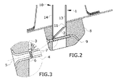
Figure 2 shows a schematic longitudinal section of an embodiment of the drain mast. -
Figure 3 shows an schematic view showing the pipe and duct of the embodiment ofFigure 2 . -
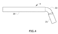
Figure 4 shows a schematic representation of an embodiment of the pipe. -
Figure 5 and 6 show schematic representations of a fairing of the embodiment shown inFigure 2 . -
Figure 1A illustrates the basic components of a known drain mast of an APU compartment of an aircraft, the drain mast comprising a tube (1) having a first end (10) connected to the APU compartment and a second end (11) for discharging the liquids to the atmosphere. The APU compartment is usually located in the tail cone of the aircraft close to the fuselage and receives the liquids leaked by the APU. The tube (1) could also be connected to a receptacle or piping of the aircraft intended to drain a fluid. - As can be seen in
Figures 1 , the distribution of the airflow in the outer surface (14) of the tube (1) opposite to the surface facing the coming airflow promotes the adherence of the droplets of liquid to the outer surface (14) of the tube (1) such that the droplet runs over said outer surface (14) as it is depicted inFigure 1B . As previously stated, another option is that the drop or drops are firstly released to the atmosphere but afterwards adhered again to the fuselage by the airflow. -
Figure 2 shows an embodiment of the invention in which the drain mast has the tube (1) comprising: - a first end (10) connected to the compartment of the aircraft,
- a second end (11) for discharging said liquids to the atmosphere and additionally this second end (11) could be configured for being located in a plane inclined with respect to the fuselage,
- an inner longitudinal surface (13) configured for being exposed to the drained liquid, and
- an outer longitudinal surface (14),
- The pipe (4) comprises an inlet (5) allowing the entrance of the coming airflow and an outlet (9) that has its longitudinal axis inclined with respect to the longitudinal axis of the inlet (5).
- The depicted embodiment also comprises a duct (6) located diametrically with respect to the pipe (4) and having an end coupled to the inner longitudinal surface (13) of the tube (1) such that the drained liquid flows from the tube (1) to the duct (6). The duct (6) further comprises an opening (7) in the side of the duct (6) pointing towards the airflow direction or, what is the same, the opening (7) is located in the face of the duct (6) opposite to the face of the duct (6) facing the incoming flow.
-
Figure 3 shows that the opening (7) of the duct (6) is located in the center of the cross-section of the pipe (4), wherein the maximum speed for the airflow is obtained, although the opening (7) could be located in a different location or the duct (6) can comprise several openings (7) in the face of the duct (6) that is located opposite to the incoming airflow, or, in the worst case, even not having a duct (6) and therefore the tube (1) directly discharging to the pipe (4). - More specifically,
Figure 4 shows an embodiment wherein the pipe (4) comprises a first straight part (20) in which the drops are released into the pipe (4) and accelerated and a second straight part (21) in which the drops are finally released to the atmosphere with an inclination with respect to the first straight part (20). The pipe (4) also comprises a bended part (22) located in between the first and the second straight parts (20, 21). The first part (20) has to be long enough to provide enough speed to the drops, obtaining a quick acceleration of them. More specifically the length of the first part (20) of the pipe (4) is between 5-22 mm to fully develop the spray. - The spray is accelerated along the first part (20) of the pipe (4), due to the small size of the droplets and the coming airflow, the inertia forces has less effect and therefore the pipe (4) can be bended avoiding in such a way a possible adherence of the spray to the inner walls of the pipe (4).
- To lead the liquid coming from the walls of the tube (1) to the pipe (4) or to duct (6) are several solutions, one is to incline the tube (1) rearwards then forcing to fall down the fluid onto the inner front face of the tube (1) and run down by gravity through this face. In this case, the longitudinal axis of the tube (1) is located in an inclined position with respect to the fuselage of the aircraft.
- Another embodiment is that the second end (11) of the tube (1) further comprises:
- an internal rim (2) located at its second end (11) connected to the inner surface (13) of the tube (1) and configured for being located in a plane inclined with respect to the horizontal plane of the fuselage, the internal rim (2) further comprising an aperture (3) being located at the lowest part of the internal rim (2) for draining the liquid,
- the internal rim (2) and the aperture (3) being configured such that at the second end (11) the liquid is directed by gravity through the internal rim (2) to the aperture (3).
- Said internal rim (2) can be located in a tube (1) having a chamfered end (11) the rim (2) being located following the profile of said chamfered end (11) or it can be located in a tube (1) with a straight end being the rim (2) in a plane inclined with respect to the fuselage.
- Therefore, drops approaching the open end runs by gravity over the internal rim (2) and are guided to the second end (11) thanks to its inclination and thus to the inclination of the internal rim (2) connected to said second end (11).
- The drain mast also comprises a fairing (8) having an aerodynamic shape to reduce drag, the fairing (8) surrounds the pipe (4) and the end of the tube (1). The faring (8) comprises two orifices, the inlet (3) and the outlet (9) of the pipe (4).
Claims (11)
- Drain mast for draining liquids from an aircraft, the drain mast comprising a tube (1) comprising:- a first end (10) configured for being connected to a source of liquids to be drained from the aircraft,- a second end (11) configured for discharging said liquids to the atmosphere,- an inner longitudinal surface (13) configured for being exposed to the drained liquid, and- an outer longitudinal surface (14),
characterized in that the drain mast further comprises a pipe (4) coupled to the inner longitudinal surface (13) of the tube (1) and configured such that the drained liquid flows from the tube (1) to the pipe (4), the pipe (4) comprising:- an inlet (5) having its longitudinal axis configured for being confronted to the coming airflow for allowing the inlet of said coming airflow into the pipe (4), and- an outlet (9) having its longitudinal axis inclined with respect to the longitudinal axis of the inlet (5) and configured for discharging the airflow and the drained liquid flowing through the pipe (4) in a direction inclined with a component perpendicular to the fuselage of the aircraft. - Drain mast for draining liquids according to claim 1 wherein the pipe (4) further comprises a duct (6) diametrically located in a cross-section of the pipe (4) and having an end coupled to the inner longitudinal surface (13) of the tube (1) such that the drained liquid flows from the tube (1) to the pipe (4) through the duct (6), the duct (6) further comprising an opening (7) in the side of the duct (6) pointing towards the airflow direction such that the opening (7) and the airflow create a suction effect that sucks the drained liquid from the duct (6) to the pipe (4).
- Drain mast for draining liquids according to claim 2, wherein the opening (7) of the duct (6) is located in the center of the cross-section of the pipe (4).
- Drain mast for draining liquids according to claim 2, wherein the duct (6) comprises several openings (7) in the side of the duct (6) pointing towards the airflow direction.
- Drain mast for draining liquids according to any preceding claim, wherein the longitudinal axis of the tube (1) is configured for being located in an inclined position with respect to the fuselage of the aircraft.
- Drain mast for draining liquids according to any preceding claim, wherein the second end (11) of the tube (1) is configured for being located in a plane inclined with respect to the fuselage of the aircraft.
- Drain mast for draining liquids, according to any preceding claim, wherein the tube (1) further comprises an internal rim (2) located at its second end (11) connected to the inner surface (13) of the drain mast (1), the internal rim (2) further comprising an aperture (3) being located at the lowest part of the internal rim (2) for draining the liquid, the internal rim (2) and the aperture (3) being configured such that at the second end (11) the liquid is directed by gravity through the internal rim (2) to the aperture (3).
- Drain mast for draining liquids, according to any preceding claim, wherein it comprises a fairing (8) enclosing the pipe (4) and the end of the tube (1) and having an aerodynamic shape for reducing drag.
- Drain mast for draining liquids, according to any preceding claim, wherein the pipe (4) comprises a first straight part (20) wherein the liquid is released into the pipe (4) and accelerated, a second straight part (21) wherein the accelerated liquid is released to the atmosphere, having the second straight part (21) an inclination with respect to the first straight part (20) and a bended part (22) located in-between the first and the second straight parts (20, 21).
- Auxiliary power unit of an aircraft comprising a drain mast according to any preceding claim.
- Aircraft comprising a drain mast according to any preceding claim 1 to 9.
Priority Applications (5)
| Application Number | Priority Date | Filing Date | Title |
|---|---|---|---|
| EP16382400.6A EP3287359B1 (en) | 2016-08-22 | 2016-08-22 | Drain mast of an aircraft |
| ES16382400T ES2732174T3 (en) | 2016-08-22 | 2016-08-22 | Drainage mast of an aircraft |
| CA2976498A CA2976498C (en) | 2016-08-22 | 2017-08-14 | Drain mast of an aircraft |
| US15/677,205 US20180050786A1 (en) | 2016-08-22 | 2017-08-15 | Drain mast of an aircraft |
| CN201710726974.1A CN107757931B (en) | 2016-08-22 | 2017-08-22 | Aircraft discharge string |
Applications Claiming Priority (1)
| Application Number | Priority Date | Filing Date | Title |
|---|---|---|---|
| EP16382400.6A EP3287359B1 (en) | 2016-08-22 | 2016-08-22 | Drain mast of an aircraft |
Publications (2)
| Publication Number | Publication Date |
|---|---|
| EP3287359A1 true EP3287359A1 (en) | 2018-02-28 |
| EP3287359B1 EP3287359B1 (en) | 2019-03-20 |
Family
ID=56799378
Family Applications (1)
| Application Number | Title | Priority Date | Filing Date |
|---|---|---|---|
| EP16382400.6A Active EP3287359B1 (en) | 2016-08-22 | 2016-08-22 | Drain mast of an aircraft |
Country Status (5)
| Country | Link |
|---|---|
| US (1) | US20180050786A1 (en) |
| EP (1) | EP3287359B1 (en) |
| CN (1) | CN107757931B (en) |
| CA (1) | CA2976498C (en) |
| ES (1) | ES2732174T3 (en) |
Cited By (1)
| Publication number | Priority date | Publication date | Assignee | Title |
|---|---|---|---|---|
| EP3312081B1 (en) * | 2016-10-20 | 2020-08-12 | Airbus Operations, S.L. | Drain mast of an aircraft |
Families Citing this family (1)
| Publication number | Priority date | Publication date | Assignee | Title |
|---|---|---|---|---|
| CN116066242B (en) * | 2023-02-27 | 2025-11-21 | 中国航发湖南动力机械研究所 | Water and oil centralized discharge structure for auxiliary power device |
Citations (3)
| Publication number | Priority date | Publication date | Assignee | Title |
|---|---|---|---|---|
| GB2376269A (en) * | 2001-06-08 | 2002-12-11 | Rolls Royce Plc | A gas turbine engine breather outlet |
| EP2829469A1 (en) * | 2013-07-22 | 2015-01-28 | Airbus Operations S.L. | Drainage mast of an aircraft compartment subjected to a negative pressure |
| EP2853482A1 (en) * | 2013-09-18 | 2015-04-01 | Goodrich Corporation | Drain mast |
Family Cites Families (2)
| Publication number | Priority date | Publication date | Assignee | Title |
|---|---|---|---|---|
| US5104069A (en) * | 1990-10-29 | 1992-04-14 | The Boeing Company | Apparatus and method for ejecting matter from an aircraft |
| US20090133376A1 (en) * | 2007-11-28 | 2009-05-28 | Zysman Steven H | Combined gearbox breather and drain mast for jet aircraft engine |
-
2016
- 2016-08-22 EP EP16382400.6A patent/EP3287359B1/en active Active
- 2016-08-22 ES ES16382400T patent/ES2732174T3/en active Active
-
2017
- 2017-08-14 CA CA2976498A patent/CA2976498C/en active Active
- 2017-08-15 US US15/677,205 patent/US20180050786A1/en not_active Abandoned
- 2017-08-22 CN CN201710726974.1A patent/CN107757931B/en active Active
Patent Citations (3)
| Publication number | Priority date | Publication date | Assignee | Title |
|---|---|---|---|---|
| GB2376269A (en) * | 2001-06-08 | 2002-12-11 | Rolls Royce Plc | A gas turbine engine breather outlet |
| EP2829469A1 (en) * | 2013-07-22 | 2015-01-28 | Airbus Operations S.L. | Drainage mast of an aircraft compartment subjected to a negative pressure |
| EP2853482A1 (en) * | 2013-09-18 | 2015-04-01 | Goodrich Corporation | Drain mast |
Cited By (1)
| Publication number | Priority date | Publication date | Assignee | Title |
|---|---|---|---|---|
| EP3312081B1 (en) * | 2016-10-20 | 2020-08-12 | Airbus Operations, S.L. | Drain mast of an aircraft |
Also Published As
| Publication number | Publication date |
|---|---|
| CN107757931A (en) | 2018-03-06 |
| US20180050786A1 (en) | 2018-02-22 |
| EP3287359B1 (en) | 2019-03-20 |
| CA2976498A1 (en) | 2018-02-22 |
| CN107757931B (en) | 2022-11-22 |
| ES2732174T3 (en) | 2019-11-21 |
| CA2976498C (en) | 2023-11-07 |
Similar Documents
| Publication | Publication Date | Title |
|---|---|---|
| US8910890B2 (en) | Seeding device | |
| EP2681111B1 (en) | A draining device | |
| US9804187B2 (en) | Aerodynamic measurement probe with evacuation of penetrated liquid by gravity | |
| US11099094B2 (en) | Pressure measuring probe, in particular for aircraft | |
| JP2013121536A5 (en) | ||
| EP3031713B1 (en) | Aircraft wing rib | |
| US5104069A (en) | Apparatus and method for ejecting matter from an aircraft | |
| CA2976498C (en) | Drain mast of an aircraft | |
| CN107021207B (en) | Aircraft flow device for passive boundary layer suction | |
| US20180265208A1 (en) | Air intake structure and airflow control system | |
| EP3205582A1 (en) | Total air temperature probe with efficient particle pass through | |
| CN110271658B (en) | Leading edge structure for an airflow control system of an aircraft | |
| WO2012010116A3 (en) | Driven aircraft, in particular an aircraft designed as a flying wing and/or having a low radar signature | |
| DE60305245D1 (en) | Noise reduction device for aircraft | |
| US10640191B2 (en) | Drain mast of an aircraft | |
| US20110138758A1 (en) | Conduit piece for the absorption of foreign bodies | |
| US10564073B2 (en) | Insert for an inflow and outflow apparatus | |
| US20150361999A1 (en) | Ventilated Drainage System | |
| EP2555975B1 (en) | Air extractor from a cockpit of a craft | |
| CN104527987A (en) | Airplane main oil tank pressure-maintaining vent system | |
| CN104986323A (en) | Glove vane aircraft | |
| BR102017022512B1 (en) | DRAINAGE MAST FOR DRAINING LIQUIDS FROM AN AIRCRAFT, AUXILIARY POWER UNIT OF AN AIRCRAFT AND AIRCRAFT | |
| EP3176081A2 (en) | A simplified fluidic oscillator for controlling aerodynamics of an aircraft | |
| CN107831176B (en) | A device for detecting slender soft parts | |
| CN106596201B (en) | An airborne sampling head capable of preventing condensation of water vapor and its application |
Legal Events
| Date | Code | Title | Description |
|---|---|---|---|
| PUAI | Public reference made under article 153(3) epc to a published international application that has entered the european phase |
Free format text: ORIGINAL CODE: 0009012 |
|
| STAA | Information on the status of an ep patent application or granted ep patent |
Free format text: STATUS: THE APPLICATION HAS BEEN PUBLISHED |
|
| AK | Designated contracting states |
Kind code of ref document: A1 Designated state(s): AL AT BE BG CH CY CZ DE DK EE ES FI FR GB GR HR HU IE IS IT LI LT LU LV MC MK MT NL NO PL PT RO RS SE SI SK SM TR |
|
| AX | Request for extension of the european patent |
Extension state: BA ME |
|
| STAA | Information on the status of an ep patent application or granted ep patent |
Free format text: STATUS: REQUEST FOR EXAMINATION WAS MADE |
|
| 17P | Request for examination filed |
Effective date: 20180809 |
|
| RBV | Designated contracting states (corrected) |
Designated state(s): AL AT BE BG CH CY CZ DE DK EE ES FI FR GB GR HR HU IE IS IT LI LT LU LV MC MK MT NL NO PL PT RO RS SE SI SK SM TR |
|
| RIC1 | Information provided on ipc code assigned before grant |
Ipc: B64C 1/14 20060101AFI20180830BHEP Ipc: B64D 41/00 20060101ALI20180830BHEP |
|
| GRAP | Despatch of communication of intention to grant a patent |
Free format text: ORIGINAL CODE: EPIDOSNIGR1 |
|
| STAA | Information on the status of an ep patent application or granted ep patent |
Free format text: STATUS: GRANT OF PATENT IS INTENDED |
|
| INTG | Intention to grant announced |
Effective date: 20181015 |
|
| RIN1 | Information on inventor provided before grant (corrected) |
Inventor name: CASADO MONTERO, CARLOS Inventor name: HERNANZ MANRIQUE, JOSE ANGEL Inventor name: MOLINA, ALBERTO |
|
| GRAS | Grant fee paid |
Free format text: ORIGINAL CODE: EPIDOSNIGR3 |
|
| GRAA | (expected) grant |
Free format text: ORIGINAL CODE: 0009210 |
|
| STAA | Information on the status of an ep patent application or granted ep patent |
Free format text: STATUS: THE PATENT HAS BEEN GRANTED |
|
| AK | Designated contracting states |
Kind code of ref document: B1 Designated state(s): AL AT BE BG CH CY CZ DE DK EE ES FI FR GB GR HR HU IE IS IT LI LT LU LV MC MK MT NL NO PL PT RO RS SE SI SK SM TR |
|
| REG | Reference to a national code |
Ref country code: GB Ref legal event code: FG4D |
|
| REG | Reference to a national code |
Ref country code: CH Ref legal event code: EP |
|
| REG | Reference to a national code |
Ref country code: DE Ref legal event code: R096 Ref document number: 602016011270 Country of ref document: DE |
|
| REG | Reference to a national code |
Ref country code: AT Ref legal event code: REF Ref document number: 1110250 Country of ref document: AT Kind code of ref document: T Effective date: 20190415 |
|
| REG | Reference to a national code |
Ref country code: IE Ref legal event code: FG4D |
|
| REG | Reference to a national code |
Ref country code: NL Ref legal event code: MP Effective date: 20190320 |
|
| PG25 | Lapsed in a contracting state [announced via postgrant information from national office to epo] |
Ref country code: SE Free format text: LAPSE BECAUSE OF FAILURE TO SUBMIT A TRANSLATION OF THE DESCRIPTION OR TO PAY THE FEE WITHIN THE PRESCRIBED TIME-LIMIT Effective date: 20190320 Ref country code: FI Free format text: LAPSE BECAUSE OF FAILURE TO SUBMIT A TRANSLATION OF THE DESCRIPTION OR TO PAY THE FEE WITHIN THE PRESCRIBED TIME-LIMIT Effective date: 20190320 Ref country code: NO Free format text: LAPSE BECAUSE OF FAILURE TO SUBMIT A TRANSLATION OF THE DESCRIPTION OR TO PAY THE FEE WITHIN THE PRESCRIBED TIME-LIMIT Effective date: 20190620 Ref country code: LT Free format text: LAPSE BECAUSE OF FAILURE TO SUBMIT A TRANSLATION OF THE DESCRIPTION OR TO PAY THE FEE WITHIN THE PRESCRIBED TIME-LIMIT Effective date: 20190320 |
|
| REG | Reference to a national code |
Ref country code: LT Ref legal event code: MG4D |
|
| PG25 | Lapsed in a contracting state [announced via postgrant information from national office to epo] |
Ref country code: BG Free format text: LAPSE BECAUSE OF FAILURE TO SUBMIT A TRANSLATION OF THE DESCRIPTION OR TO PAY THE FEE WITHIN THE PRESCRIBED TIME-LIMIT Effective date: 20190620 Ref country code: GR Free format text: LAPSE BECAUSE OF FAILURE TO SUBMIT A TRANSLATION OF THE DESCRIPTION OR TO PAY THE FEE WITHIN THE PRESCRIBED TIME-LIMIT Effective date: 20190621 Ref country code: HR Free format text: LAPSE BECAUSE OF FAILURE TO SUBMIT A TRANSLATION OF THE DESCRIPTION OR TO PAY THE FEE WITHIN THE PRESCRIBED TIME-LIMIT Effective date: 20190320 Ref country code: NL Free format text: LAPSE BECAUSE OF FAILURE TO SUBMIT A TRANSLATION OF THE DESCRIPTION OR TO PAY THE FEE WITHIN THE PRESCRIBED TIME-LIMIT Effective date: 20190320 Ref country code: LV Free format text: LAPSE BECAUSE OF FAILURE TO SUBMIT A TRANSLATION OF THE DESCRIPTION OR TO PAY THE FEE WITHIN THE PRESCRIBED TIME-LIMIT Effective date: 20190320 Ref country code: RS Free format text: LAPSE BECAUSE OF FAILURE TO SUBMIT A TRANSLATION OF THE DESCRIPTION OR TO PAY THE FEE WITHIN THE PRESCRIBED TIME-LIMIT Effective date: 20190320 |
|
| REG | Reference to a national code |
Ref country code: AT Ref legal event code: MK05 Ref document number: 1110250 Country of ref document: AT Kind code of ref document: T Effective date: 20190320 |
|
| PG25 | Lapsed in a contracting state [announced via postgrant information from national office to epo] |
Ref country code: IT Free format text: LAPSE BECAUSE OF FAILURE TO SUBMIT A TRANSLATION OF THE DESCRIPTION OR TO PAY THE FEE WITHIN THE PRESCRIBED TIME-LIMIT Effective date: 20190320 Ref country code: CZ Free format text: LAPSE BECAUSE OF FAILURE TO SUBMIT A TRANSLATION OF THE DESCRIPTION OR TO PAY THE FEE WITHIN THE PRESCRIBED TIME-LIMIT Effective date: 20190320 Ref country code: SK Free format text: LAPSE BECAUSE OF FAILURE TO SUBMIT A TRANSLATION OF THE DESCRIPTION OR TO PAY THE FEE WITHIN THE PRESCRIBED TIME-LIMIT Effective date: 20190320 Ref country code: RO Free format text: LAPSE BECAUSE OF FAILURE TO SUBMIT A TRANSLATION OF THE DESCRIPTION OR TO PAY THE FEE WITHIN THE PRESCRIBED TIME-LIMIT Effective date: 20190320 Ref country code: EE Free format text: LAPSE BECAUSE OF FAILURE TO SUBMIT A TRANSLATION OF THE DESCRIPTION OR TO PAY THE FEE WITHIN THE PRESCRIBED TIME-LIMIT Effective date: 20190320 Ref country code: PT Free format text: LAPSE BECAUSE OF FAILURE TO SUBMIT A TRANSLATION OF THE DESCRIPTION OR TO PAY THE FEE WITHIN THE PRESCRIBED TIME-LIMIT Effective date: 20190720 Ref country code: AL Free format text: LAPSE BECAUSE OF FAILURE TO SUBMIT A TRANSLATION OF THE DESCRIPTION OR TO PAY THE FEE WITHIN THE PRESCRIBED TIME-LIMIT Effective date: 20190320 |
|
| REG | Reference to a national code |
Ref country code: ES Ref legal event code: FG2A Ref document number: 2732174 Country of ref document: ES Kind code of ref document: T3 Effective date: 20191121 |
|
| PG25 | Lapsed in a contracting state [announced via postgrant information from national office to epo] |
Ref country code: PL Free format text: LAPSE BECAUSE OF FAILURE TO SUBMIT A TRANSLATION OF THE DESCRIPTION OR TO PAY THE FEE WITHIN THE PRESCRIBED TIME-LIMIT Effective date: 20190320 Ref country code: SM Free format text: LAPSE BECAUSE OF FAILURE TO SUBMIT A TRANSLATION OF THE DESCRIPTION OR TO PAY THE FEE WITHIN THE PRESCRIBED TIME-LIMIT Effective date: 20190320 |
|
| PG25 | Lapsed in a contracting state [announced via postgrant information from national office to epo] |
Ref country code: AT Free format text: LAPSE BECAUSE OF FAILURE TO SUBMIT A TRANSLATION OF THE DESCRIPTION OR TO PAY THE FEE WITHIN THE PRESCRIBED TIME-LIMIT Effective date: 20190320 Ref country code: IS Free format text: LAPSE BECAUSE OF FAILURE TO SUBMIT A TRANSLATION OF THE DESCRIPTION OR TO PAY THE FEE WITHIN THE PRESCRIBED TIME-LIMIT Effective date: 20190720 |
|
| REG | Reference to a national code |
Ref country code: DE Ref legal event code: R097 Ref document number: 602016011270 Country of ref document: DE |
|
| PLBE | No opposition filed within time limit |
Free format text: ORIGINAL CODE: 0009261 |
|
| STAA | Information on the status of an ep patent application or granted ep patent |
Free format text: STATUS: NO OPPOSITION FILED WITHIN TIME LIMIT |
|
| PG25 | Lapsed in a contracting state [announced via postgrant information from national office to epo] |
Ref country code: DK Free format text: LAPSE BECAUSE OF FAILURE TO SUBMIT A TRANSLATION OF THE DESCRIPTION OR TO PAY THE FEE WITHIN THE PRESCRIBED TIME-LIMIT Effective date: 20190320 |
|
| 26N | No opposition filed |
Effective date: 20200102 |
|
| PG25 | Lapsed in a contracting state [announced via postgrant information from national office to epo] |
Ref country code: SI Free format text: LAPSE BECAUSE OF FAILURE TO SUBMIT A TRANSLATION OF THE DESCRIPTION OR TO PAY THE FEE WITHIN THE PRESCRIBED TIME-LIMIT Effective date: 20190320 |
|
| PG25 | Lapsed in a contracting state [announced via postgrant information from national office to epo] |
Ref country code: TR Free format text: LAPSE BECAUSE OF FAILURE TO SUBMIT A TRANSLATION OF THE DESCRIPTION OR TO PAY THE FEE WITHIN THE PRESCRIBED TIME-LIMIT Effective date: 20190320 |
|
| PG25 | Lapsed in a contracting state [announced via postgrant information from national office to epo] |
Ref country code: LI Free format text: LAPSE BECAUSE OF NON-PAYMENT OF DUE FEES Effective date: 20190831 Ref country code: MC Free format text: LAPSE BECAUSE OF FAILURE TO SUBMIT A TRANSLATION OF THE DESCRIPTION OR TO PAY THE FEE WITHIN THE PRESCRIBED TIME-LIMIT Effective date: 20190320 Ref country code: CH Free format text: LAPSE BECAUSE OF NON-PAYMENT OF DUE FEES Effective date: 20190831 Ref country code: LU Free format text: LAPSE BECAUSE OF NON-PAYMENT OF DUE FEES Effective date: 20190822 |
|
| REG | Reference to a national code |
Ref country code: BE Ref legal event code: MM Effective date: 20190831 |
|
| PG25 | Lapsed in a contracting state [announced via postgrant information from national office to epo] |
Ref country code: IE Free format text: LAPSE BECAUSE OF NON-PAYMENT OF DUE FEES Effective date: 20190822 |
|
| PG25 | Lapsed in a contracting state [announced via postgrant information from national office to epo] |
Ref country code: BE Free format text: LAPSE BECAUSE OF NON-PAYMENT OF DUE FEES Effective date: 20190831 |
|
| PG25 | Lapsed in a contracting state [announced via postgrant information from national office to epo] |
Ref country code: CY Free format text: LAPSE BECAUSE OF FAILURE TO SUBMIT A TRANSLATION OF THE DESCRIPTION OR TO PAY THE FEE WITHIN THE PRESCRIBED TIME-LIMIT Effective date: 20190320 |
|
| PG25 | Lapsed in a contracting state [announced via postgrant information from national office to epo] |
Ref country code: MT Free format text: LAPSE BECAUSE OF FAILURE TO SUBMIT A TRANSLATION OF THE DESCRIPTION OR TO PAY THE FEE WITHIN THE PRESCRIBED TIME-LIMIT Effective date: 20190320 Ref country code: HU Free format text: LAPSE BECAUSE OF FAILURE TO SUBMIT A TRANSLATION OF THE DESCRIPTION OR TO PAY THE FEE WITHIN THE PRESCRIBED TIME-LIMIT; INVALID AB INITIO Effective date: 20160822 |
|
| PG25 | Lapsed in a contracting state [announced via postgrant information from national office to epo] |
Ref country code: MK Free format text: LAPSE BECAUSE OF FAILURE TO SUBMIT A TRANSLATION OF THE DESCRIPTION OR TO PAY THE FEE WITHIN THE PRESCRIBED TIME-LIMIT Effective date: 20190320 |
|
| PGFP | Annual fee paid to national office [announced via postgrant information from national office to epo] |
Ref country code: ES Payment date: 20250926 Year of fee payment: 10 |
|
| PGFP | Annual fee paid to national office [announced via postgrant information from national office to epo] |
Ref country code: DE Payment date: 20250820 Year of fee payment: 10 |
|
| PGFP | Annual fee paid to national office [announced via postgrant information from national office to epo] |
Ref country code: GB Payment date: 20250821 Year of fee payment: 10 |
|
| PGFP | Annual fee paid to national office [announced via postgrant information from national office to epo] |
Ref country code: FR Payment date: 20250828 Year of fee payment: 10 |