EP3287348A1 - Seat lock structure for saddle riding vehicle - Google Patents
Seat lock structure for saddle riding vehicle Download PDFInfo
- Publication number
- EP3287348A1 EP3287348A1 EP15889927.8A EP15889927A EP3287348A1 EP 3287348 A1 EP3287348 A1 EP 3287348A1 EP 15889927 A EP15889927 A EP 15889927A EP 3287348 A1 EP3287348 A1 EP 3287348A1
- Authority
- EP
- European Patent Office
- Prior art keywords
- bracket
- seat
- seat lock
- lock mechanism
- key cylinder
- Prior art date
- Legal status (The legal status is an assumption and is not a legal conclusion. Google has not performed a legal analysis and makes no representation as to the accuracy of the status listed.)
- Granted
Links
Images



Classifications
-
- E—FIXED CONSTRUCTIONS
- E05—LOCKS; KEYS; WINDOW OR DOOR FITTINGS; SAFES
- E05B—LOCKS; ACCESSORIES THEREFOR; HANDCUFFS
- E05B83/00—Vehicle locks specially adapted for particular types of wing or vehicle
- E05B83/16—Locks for luggage compartments, car boot lids or car bonnets
-
- B—PERFORMING OPERATIONS; TRANSPORTING
- B62—LAND VEHICLES FOR TRAVELLING OTHERWISE THAN ON RAILS
- B62J—CYCLE SADDLES OR SEATS; AUXILIARY DEVICES OR ACCESSORIES SPECIALLY ADAPTED TO CYCLES AND NOT OTHERWISE PROVIDED FOR, e.g. ARTICLE CARRIERS OR CYCLE PROTECTORS
- B62J1/00—Saddles or other seats for cycles; Arrangement thereof; Component parts
- B62J1/12—Box-shaped seats; Bench-type seats, e.g. dual or twin seats
-
- B—PERFORMING OPERATIONS; TRANSPORTING
- B62—LAND VEHICLES FOR TRAVELLING OTHERWISE THAN ON RAILS
- B62J—CYCLE SADDLES OR SEATS; AUXILIARY DEVICES OR ACCESSORIES SPECIALLY ADAPTED TO CYCLES AND NOT OTHERWISE PROVIDED FOR, e.g. ARTICLE CARRIERS OR CYCLE PROTECTORS
- B62J1/00—Saddles or other seats for cycles; Arrangement thereof; Component parts
- B62J1/14—Separate pillions
-
- B—PERFORMING OPERATIONS; TRANSPORTING
- B62—LAND VEHICLES FOR TRAVELLING OTHERWISE THAN ON RAILS
- B62K—CYCLES; CYCLE FRAMES; CYCLE STEERING DEVICES; RIDER-OPERATED TERMINAL CONTROLS SPECIALLY ADAPTED FOR CYCLES; CYCLE AXLE SUSPENSIONS; CYCLE SIDECARS, FORECARS, OR THE LIKE
- B62K11/00—Motorcycles, engine-assisted cycles or motor scooters with one or two wheels
- B62K11/02—Frames
- B62K11/04—Frames characterised by the engine being between front and rear wheels
-
- E—FIXED CONSTRUCTIONS
- E05—LOCKS; KEYS; WINDOW OR DOOR FITTINGS; SAFES
- E05B—LOCKS; ACCESSORIES THEREFOR; HANDCUFFS
- E05B83/00—Vehicle locks specially adapted for particular types of wing or vehicle
-
- E—FIXED CONSTRUCTIONS
- E05—LOCKS; KEYS; WINDOW OR DOOR FITTINGS; SAFES
- E05B—LOCKS; ACCESSORIES THEREFOR; HANDCUFFS
- E05B85/00—Details of vehicle locks not provided for in groups E05B77/00 - E05B83/00
- E05B85/06—Lock cylinder arrangements
Definitions
- the present invention relates to a seat lock structure for a saddle riding vehicle in which a seat lock mechanism is directly operated by a key cylinder.
- Patent Literature 1 and Patent Literature 2 the theft prevention is performed by covering a seat lock mechanism with a peripheral part or an external part of the seat lock mechanism, but this causes enlargement of a structure around the seat lock mechanism. The volume of the storage space provided under the seat is therefore restricted.
- the present invention provides a seat lock structure for a saddle riding vehicle, including a seat (17, 57) on which a rider or a passenger sits, a key cylinder (91), and a seat lock mechanism (87) to open and close the seat (17, 57) by a key operation of the key cylinder (91),
- the key cylinder (91) includes a turning arm (118) which is turned by the key operation
- the seat lock mechanism (87) includes a first bracket (141) which is fixed to a vehicle body frame (10A), and a second bracket (142) which is slidably supported on the first bracket (141) and engageable with a seat (17, 57) side, and the second bracket (142) is slid by being pressed by the turning arm (118), and a slide regulating portion (142g) formed on the second bracket (142) regulates the second bracket (142) from being slid when the turning arm (118) is unturnable.
- an article storage part (85) for storing articles may be formed below the seat (17, 57), and the seat lock mechanism (87) may be provided in the article storage part (85).
- the article storage part (85) may be configured to spread downward and rearward of the seat lock mechanism (87).
- the key cylinder (91) and the seat lock mechanism (87) may be disposed so as to be at least partially overlapped with each other in a forward-rearward direction.
- the slide regulating portion (142g) may be disposed at a lower portion of the key cylinder (91).
- a striker (97) may be provided below the seat (17, 57), a slit (141g) into which the striker (97) is inserted may be formed in the first bracket (141), and a locking pawl (142e) which is disposed close to one side of the slit (141g) and is engageable with the striker (97) inserted into the slit (141g) may be formed in the second bracket (142), so that the locking pawl (142e) is disposed between the key cylinder (91) and the slit (141g).
- a key cylinder of the present invention includes a turning arm which is turned by a key operation
- a seat lock mechanism includes a first bracket which is fixed to a vehicle body frame, and a second bracket which is slidably supported on the first bracket and engageable with a seat side, the second bracket is slid by being pressed by the turning arm, and a slide regulating portion formed on the second bracket regulates the second bracket from being slid when the turning arm is unturnable. Therefore, the second bracket can be prevented from being forcibly slid without the key by providing the slide regulating portion on the second bracket.
- the seat lock mechanism can be downsized as compared to a case where a guard member for preventing tampering with the second bracket is provided to a peripheral part of the seat lock mechanism.
- An article storage part for storing articles is formed below a seat, and the seat lock mechanism is provided in the article storage part. Therefore, the storage space of the article storage part can be increased by downsizing the seat lock mechanism, thereby improving the usability.
- the article storage part which spreads downward and rearward of the seat lock mechanism has a configuration in which articles such as a tool box and a U-shaped lock member can be easily taken in and out from the article storage part, thereby improving the usability of the article storage part.
- the key cylinder and the seat lock mechanism are disposed so as to be at least partially overlapped with each other in the forward-rearward direction, thereby enabling occupied spaces of the key cylinder and the seat lock mechanism to be reduced in the forward-rearward direction, and increasing a volume of the article storage part.
- the slide regulating portion is disposed below the key cylinder, thereby enabling the second bracket to be easily slid horizontally when the turning arm is turned, and simplifying an engagement structure of the second bracket with the seat side which is opened and closed up and down.
- a striker is provided below the seat, a slit into which the striker is inserted is formed in the first bracket, and a locking pawl which is disposed close to one side of the slit and is engageable with the striker inserted into the slit is formed in the second bracket, so that the locking pawl is disposed between the key cylinder and the slit. Therefore, the locking pawl is disposed between the key cylinder and the slit, thereby preventing the tampering with the locking pawl.
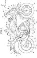
- Fig. 1 is a right side elevational view of a motorcycle 10 provided with a seat lock mechanism according to the present invention.
- the motorcycle 10 is a saddle riding vehicle in which a front wheel 13 is supported on a front end portion of a vehicle body frame 10A through a front fork 12, a rear wheel 16 is supported on a lower portion of the vehicle body frame 10A through a swing arm 14, and a main seat 17 for a rider is supported on an upper portion of the vehicle body frame 10A.
- the vehicle body frame 10A includes: a head pipe 10b; a pair of left and right main frames 10c; a pair of left and right pivot frames 10d; a down frame 10e; a pair of left and right seat frames 10f (see Fig. 7 ); and a pair of left and right sub frames 10g.
- the head pipe 10b steerably supports the front fork 12.
- the left and right main frames 10c extend obliquely rearwardly and downwardly from the head pipe 10b.
- the pivot frames 10d extend substantially downwardly from rear ends of the main frames 10c.
- the down frame 10e extends substantially downwardly from the head pipe 10b.
- the seat frames 10f extend obliquely rearwardly and upwardly from upper end portions of the pivot frames 10d to support the main seat 17.
- the sub frames 10g extend obliquely rearwardly and upwardly from upper portions of the pivot frames 10d and in lower sides of the seat frames 10f so as to be connected to rear portions of the seat frames 10f.
- the front fork 12 is attached at an upper portion thereof with a bar steering handle 21, and supports at a lower portion thereof the front wheel 13 through a wheel shaft 22.
- a front end portion of the swing arm 14 is swingably supported on a pivot shaft 23 which is provided to the left and right pivot frames 10d, and a rear end portion of the swing arm 14 supports the rear wheel 16 through a wheel shaft 24.
- An engine 26 is supported on a center portion of the vehicle body frame 10A, and transmits power to the rear wheel 16 through a chain 28 from a transmission 27 integrally provided with the engine 26.
- a fuel tank 29 is supported on the left and right main frames 10c above the engine 26.
- a tank pad 65 is provided to a rear portion of the fuel tank 29.
- the pivot frames 10d and the down frame 10e support the engine 26.
- the engine 26 includes a crankcase 26a in which a crankshaft is rotatably housed, and a cylinder part 26b rising obliquely upwardly and forwardly from an upper portion at a front of the crankcase 26a.
- An intake device 36 is connected to a rear portion of the cylinder part 26b.
- the intake device 36 includes an air cleaner box 37, and an intake duct 38 which is connected to a rear portion of the air cleaner box 37.
- An exhaust device 39 is connected to a front portion of the cylinder part 26b.
- the motorcycle 10 is covered by a vehicle body cover 31.
- the vehicle body cover 31 includes a front cowl 32, a pair of left and right side cowls 33, and a pair of left and right rear side body covers 34.
- the front cowl 32 includes an upper cowl 41, a pair of left and right middle cowls 42, and a pair of left and right lower cowls 43.
- the upper cowl 41 includes a center upper cowl 45 which forms a front surface of the front cowl 32, and is located at a center in a vehicle width direction and in a lower portion of the upper cowl 41, and a pair of left and right side upper cowls 46 which are located outside the vehicle width direction, and a windscreen 47 is mounted on the left and right side upper cowls 46.
- a headlight 51 is disposed below the side upper cowls 46.
- the middle cowls 42 form left and right side surfaces of the front cowl 32, and each of the middle cowls 42 covers a front portion of the vehicle body to a position lower than the wheel shaft 22 of the front wheel 13 from a side of the vehicle body.
- Each of the lower cowls 43 extends to the side of the lower portion of the engine 26 from the front end portion of the lower cowl 43 which is connected to the lower end portion of the middle cowl 42.
- the side cowl 33 consists of a substantially V-shaped inner side cowl 54, and an inverse triangular-shaped outer side cowl 55 which covers the outside of the upper portion of the inner side cowl 54.
- the side cowl 33 covers the lower portions of the main seat 17 and the fuel tank 29 from the side of the vehicle body.
- the rear side body cover 34 covers, from the side of the vehicle body, a lower side of a side edge portion of each of a rear portion of the main seat 17 for a rider, and a rear seat 57 for a passenger which is disposed at a rear of the main seat 17.
- the air cleaner box 37 and the intake duct 38 are disposed inside the side cowl 33 in the vehicle width direction, particularly the intake duct 38 is disposed inside a rear portion of the inner side cowl 54 in the vehicle width direction.
- a reference numeral 61 in the figure represents a front fender which covers the front wheel 13 from above, a reference numeral 62 represents a pair of left and right rearview mirrors which are mounted on the side upper cowls 46, respectively, and a reference numeral 63 represents a pair of left and right front winkers which are mounted on front and upper portions of the middle cowls 42, respectively.
- a reference numeral 64 represents a pair of left and right steps for a rider
- a reference numeral 66 represents a pair of left and right plate members which are attached to side surfaces in the lower portions of the pivot frames 10d, respectively
- a reference numeral 67 represents a rear fender which covers the rear wheel 16 from above
- a reference numeral 69 represents a side stand which is attached to a lower end portion of the left pivot frame 10d
- a reference numeral 73 represents a pair of left and right rear winkers which are mounted on the rear fender 67
- reference numerals 74, 75 are an exhaust pipe and a muffler, respectively, the exhaust pipe and the muffler constituting the exhaust device 39.
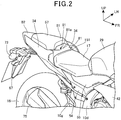
- Fig. 2 is a perspective view illustrating a seat lock device 115 (see Fig. 3 ) of the rear seat 57 and its surrounding.
- a center cowl 81 is provided at the rear of the main seat 17 so as to connect front ends at upper portions of respective left and right rear side body covers 34.
- a rear center cowl 82 is provided at the rear of the rear seat 57 so as to connect upper edges at the rear end portions of respective left and right rear side body covers 34.
- An article storage part 85 (see Fig. 3 ) is formed in a space surrounded by the left and right rear side body covers 34, the center cowl 81 and the rear center cowl 82 which are described above.
- An opening 86 (see Fig. 6 ) formed by the left and right rear side body covers 34, the center cowl 81 and the rear center cowl 82, that is, the opening 86 above the article storage part 85 is covered by the rear seat 57.
- the rear seat 57 is configured to be detachable and attachable from/to the vehicle body, and is locked by the seat lock device 115 provided in the article storage part 85.
- a circular hole 81a is opened in a center of the center cowl 81 in the vehicle width direction, and a key cylinder 91 constituting the seat lock device 115 is disposed inside the circular hole 81a.
- Fig. 3 is a right side sectional view in which a rear portion of the motorcycle 10 is cut along a center line in the vehicle width direction.
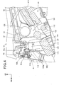
- Fig. 4 is a left side sectional view in which the rear portion of the motorcycle 10 is cut along the center line in the vehicle width direction.
- a bridge member 93 which extends in the vehicle width direction is attached to the left and right seat frames 10f, and the seat lock device 115 is provided to the bridge member 93.
- the key cylinder 91 and a seat lock mechanism 87 constituting the seat lock device 115 are disposed in the article storage part 85.
- the article storage part 85 extends downwardly and rearwardly of the seat lock device 115.
- the above-described bridge member 93 is a component of the vehicle body frame 10A (see Fig. 1 ).
- the rear seat 57 includes a seat cushion member 95 having elasticity, and a bottom plate 96 which is provided on a bottom surface of the seat cushion member 95.
- the bottom plate 96 is integrally formed at a rear portion thereof with a hook 96a which protrudes downwardly and rearwardly, and is provided at a front portion thereof with a substantially U-shaped striker 97 which protrudes downwardly.
- the hook 96a is engaged with a rear engaging part 98a of a rear bracket 98 provided between the left and right seat frames 10f, the striker 97 is engaged with the seat lock device 115, and the rear seat 57 is fixed to the vehicle body side in the locked state.
- the rear fender 67 is attached through a fender stay 102 to a rear end portion of a rear lower cowl 101 which forms a bottom wall of the article storage part 85.
- a reference numeral 104 represents a wire harness which energizes the rear winkers 73 (see Fig. 1 ) and a license plate lamp for illuminating a license plate which is attached to the rear fender 67.
- the article storage part 85 is surrounded by the center cowl 81 on a front side of the article storage part 85, the rear center cowl 82 and a tail lamp 105 disposed below the rear center cowl 82 on a rear side of the article storage part 85, the rear lower cowl 101 on a lower side of the article storage part 85, the rear seat 57 on an upper side of the article storage part 85, and the rear side body covers 34 on left and right sides of the article storage part 85.
- the article storage part 85 houses at a front and lower portion thereof a tool box 111 and a U-shaped lock member 112, and houses at a rear portion thereof an ETC in-vehicle unit 113.
- the bridge member 93 includes an upper wall 93a which extends in the vehicle width direction, and a front wall 93b which extends substantially downwardly from a front edge of the upper wall 93a.
- the front wall 93b is formed to extend along a front wall 81b of the center cowl 81.
- the upper wall 93a is attached with the seat lock mechanism 87 which is engaged with the striker 97, the front wall 93b is attached with the key cylinder 91 disposed to face the circular hole 81a in the center cowl 81.
- the key cylinder 91 and the seat lock mechanism 87 constitute the seat lock device 115.
- the seat lock mechanism 87 includes a first bracket 141 which is attached to a lower surface of the upper wall 93a of the bridge member 93, and a second bracket 142 which is slidably attached to the first bracket 141 to be engaged or unengaged with the striker 97 of the rear seat 57.
- the second bracket 142 is engaged with a turning arm 118 of the key cylinder 91 to be slid to both sides in the vehicle width direction by turning of the turning arm 118.
- a reference numeral 135 represents an accessory socket provided in the article storage part 85.
- Fig. 5 is a sectional view illustrating the key cylinder 91.
- the key cylinder 91 includes an outer cylinder 116, a turning member 117 which is turnably inserted into the outer cylinder 116, and the turning arm 118 which is integrally provided to one end portion of the turning member 117.
- the outer cylinder 116 includes a main body 121, and a cylindrical member 122 which is fixed inside the main body 121.
- the turning member 117 includes a key insertion hole 117a into which a key is inserted, a plurality of axis orthogonal holes 117b which are opened in a direction orthogonal to an axis of the turning member 117, and tumblers 124 each of which is inserted into the axis orthogonal hole 117b.
- the tumblers 124 are moved in the axis orthogonal holes 117b when the key is inserted into the key insertion hole 117a.
- the tumblers 124 are slid out of axis orthogonal holes (not illustrated) provided in the cylindrical member 122 of the outer cylinder 116, thereby enabling the turning member 117 to be turnable with respect to the cylindrical member 122.
- the tumblers 124 are inserted into both of the axis orthogonal holes 117b in the turning member 117 and the axis orthogonal holes in the cylindrical member 122 so that the turning member 117 is unturnable with respect to the cylindrical member 122.
- One end surface of the outer cylinder 116 is blocked by a plate 126, and the turning member 117 extends to pass through the plate 126.
- the turning arm 118 is relatively unturnably supported on the turning member 117, is disposed to be adjacent to the plate 126, and is held by a retaining ring 127 provided to the turning member 117.
- a compression coil spring 131 is disposed between the plate 126 and a step portion 121a provided in an inner periphery surface of the outer cylinder 116. The compression coil spring 131 biases the turning member 117 through the plate 126 and the turning arm 118 so that the turning member 117 does not get out of the outer cylinder 116.
- a reference numeral 133 represents a cover member which blocks the outer cylinder 116 and a part of an end surface of the turning member 117, the cover member 133 being provided with a key insertion opening 133a.
- Fig. 6 is a plan view illustrating a vehicle body rear portion with the rear seat 57 removed.
- the bridge member 93, the rear bracket 98, the U-shaped lock member 112, the ETC in-vehicle unit 113, and the accessory socket 135 are exposed from the opening 86 of the article storage part 85 provided in the vehicle body rear portion.
- a striker insertion hole 93c which is long in a forward-rearward direction of the vehicle body is opened in a center portion in the vehicle width direction of the upper wall 93a of the bridge member 93, in order to pass through the striker 97 (see Fig. 4 ).
- a mounting portion 81c of the center cowl 81 is attached by a screw 145 to a left side of the striker insertion hole 93c, and the first bracket 141 of the seat lock mechanism 87 is attached by a bolt 146 to a right side of the striker insertion hole 93c.
- the rear bracket 98 is formed in a U shape in a top plan view so as to have the rear engaging part 98a in the rear portion of the rear bracket 98.
- the screw 145 and the bolt 146 are covered by the rear seat 57, and therefore such fixing members are not exposed to outside, thereby improving the appearance.
- Fig. 7 is a sectional view taken along line VII-VII of Fig. 1 .
- the substantially inverted U-shaped bridge member 93 is provided between the left and right seat frames 10f, 10f, and the key cylinder 91 and the seat lock mechanism 87 are supported on an upper portion of the bridge member 93.
- the key cylinder 91 is located at a center in the vehicle width direction of the vehicle body rear portion.
- the substantially inverted U-shaped bridge member 93 enables the seat lock mechanism 87 to be located below the upper wall 93a of the bridge member 93, and a volume of the article storage part 85 to be secured.
- the rear lower cowl 101 has a curved sectional shape so that the center portion in the vehicle width direction is higher than outside the vehicle width direction, and is integrally formed with a pair of left and right side walls 101a, 101a which are provided inside the vehicle width direction of the left and right sub frames 10g, 10g and protrude upwardly from the rear lower cowl 101.
- a U-shaped lock member 112 is disposed inside the left and right side walls 101a, 101a, and a tool box 111 is disposed in the upper portion of the left and right side walls 101a, 101a.
- a pair of left and right louvers 151, 151 are disposed outside the bridge member 93 in the vehicle width direction.
- the louver 151 is a member for introducing outside air into the vehicle body cover 31, and the introduced outside air is supplied to the engine 26 through the intake duct 38 and the air cleaner box 37 illustrated in Fig. 1 .
- a reference numeral 152 is a rear cross member provided between the left and right sub frames 10g, 10g which serves as a component of the vehicle body frame 10A (see Fig. 1 ).
- Fig. 8 is a perspective view illustrating the seat lock mechanism 87.
- the seat lock mechanism 87 includes the first bracket 141 which is attached to the bridge member 93 (see Fig. 4 ), the second bracket 142 (a part indicated by a plurality of dots; the same shall apply hereinafter) which is attached to the first bracket 141 so as to be movable in a vehicle lateral direction (vehicle width direction), and a tension coil spring 143 provided between the first bracket 141 and the second bracket 142 to bias the second bracket 142 toward an engaging side with striker 97 (see Fig. 4 ).
- the first bracket 141 is integrally formed of a forward-descending attachment portion 141a which is attached to the bridge member 93, a rear wall 141b which extends substantially downwardly from a rear edge of the attachment portion 141a, a lower end bent portion 141c which is bent forwardly from a lower edge of the rear wall 141b, and an L-shaped bent portion 141d which continuously extends to the rear portion of the attachment portion 141a and extends forwardly and downwardly from a right upper edge portion of the rear wall 141b.
- the attachment portion 141a includes a bolt insertion hole 141e for passing the bolt 146 (see Fig. 6 ) for fastening to the bridge member 93, and a positioning protrusion 141f which is provided to protrude upwardly at a front of the bolt insertion hole 141e.
- the positioning protrusion 141f is fitted in a protrusion insertion hole (not illustrated) which is opened to the bridge member 93.
- a nut 153 into which the bolt 146 is screwed is attached to a bottom surface of the attachment portion 141a, and a female thread of the nut 153 matches the bolt insertion hole 141e.
- the rear wall 141b has a vertically long slit 141g into which the striker 97 is inserted (see Fig. 4 ).
- the second bracket 142 is integrally formed of a vertical wall 142a which slides with the rear wall 141b of the first bracket 141, a front extension portion 142b which extends forwardly from the lower portion of the vertical wall 142a, a right bent portion 142c which is bent forwardly from a right edge of the vertical wall 142a, and a locking pawl 142e which protrudes to the side from a left edge of the vertical wall 142a.
- the vertical wall 142a includes a pair of oblong holes 142d into which holding members 155 that are attached to the rear wall 141b of the first bracket 141 are inserted.
- the front extension portion 142b includes a longitudinally placed planar extension portion main body 142f, and an L-shaped end portion 142g which is formed to extend leftwardly and upwardly from a lower portion of a distal end of the extension portion main body 142f.
- the right bent portion 142c has a spring end insertion hole 142h opened to insert one end of the tension coil spring 143. Both ends of the tension coil spring 143 are hooked on the L-shaped bent portion 141d of the first bracket 141 and the right bent portion 142c, respectively.
- the locking pawl 142e overlaps with the slit 141g of the first bracket 141 in the forward-rearward direction when being moved in the leftward direction, but does not overlap with the slit 141g when being moved in the rightward direction.
- the second bracket 142 is moved in the leftward direction with respect to the first bracket 141 by a tensile force of the tension coil spring 143, and the locking pawl 142e overlaps with the slit 141g in the forward-rearward direction.
- Figs. 9A and 9B each are an explanatory view for describing the seat lock mechanism 87.
- Fig. 9A is an elevation view of the seat lock mechanism 87
- Fig. 9B is a left side elevational view of the seat lock mechanism 87.
- the L-shaped bent portion 141d of the first bracket 141 includes a spring hooking portion 141p which hooks the tension coil spring 143 and extends vertically.
- a spring hooking recess portion 141j for hooking the end portion of the tension coil spring 143 is formed in a lower portion of a side end surface 141h of the spring hooking portion 141p.
- the slit 141g of the first bracket 141 consists of a tapered portion 141k which is formed so that a width in the vehicle width direction of the tapered portion 141k is gradually reduced as it goes downwardly, and a straight portion 141m which extends downwardly so that the width in the vehicle width direction becomes substantially uniform from a lower end of the tapered portion 141k.
- Such a shape of the slit 141g enables the striker 97 to be easily inserted into the slit 141g from above.
- the holding member 155 is integrally formed of a shaft portion 155a which is attached to the rear wall 141b of the first bracket 141, and is inserted into oblong holes 142d of the second bracket 142, and a flange 155b which is formed larger than an outer diameter of the shaft portion 155a at an end portion of the shaft portion 155a.
- a front end portion of the extension portion main body 142f of the front extension portion 142b and the L-shaped end portion 142g constitute an engagement portion 142j having a substantially U-shape or a substantially inverted J-shape in a front view where the turning arm 118 of the key cylinder 91 enters to be engaged therewith.
- the engagement between the turning arm 118 and the engagement portion 142j is not disengaged in all ranges where the second bracket 142 is slid by turning of the turning arm 118.
- the locking pawl 142e of the second bracket 142 is formed so that a lower edge has a substantially horizontal flat surface, and is located above the striker 97 which is inserted into the slit 141g of the first bracket 141, thereby preventing the striker 97 from being moved upwardly.
- the attachment portion 141a inclines downwardly toward the front, and the rear wall 141b inclines forwardly.
- the vertical wall 142a inclines forwardly, and the front extension portion 142b inclines downwardly toward the front.
- the key cylinder 91 and the seat lock mechanism 87 are disposed so that partial portions of them (between a rear end portion of the key cylinder 91 and a front end portion of the attachment portion 141a of the seat lock mechanism 87, and between the rear end portion of the key cylinder 91 and a front end portion of the front extension portion 142b) are overlapped with each other in the forward-rearward direction, and the key cylinder 91 is disposed forward of the locking pawl (see Fig. 9A ) of the second bracket 142.
- An axial line 91a of the key cylinder 91 (for more details, the axial line 91a of the turning member 117 (see Fig. 5 )) inclines upwardly toward the front, and the turning arm 118 of the key cylinder 91 extends along the engagement portion 142j of the second bracket 142.
- the holding member 155 has a female thread 155c formed in the shaft portion 155a, and a hexagon socket head bolt 157 which is inserted into the bolt insertion hole 141n formed in the rear wall 141b of the first bracket 141 is screwed in the female thread 155c of the shaft portion 155a to attach the holding member 155 to the rear wall 141b.
- the spring hooking portion 141p of the L-shaped bent portion 141d in the first bracket 141 is formed substantially parallel to the rear wall 141b, and overlaps with the right bent portion 142c of the second bracket 142 in a side view.
- Each of the first bracket 141 and the second bracket 142 is formed by bending a sheet of plate, and the second bracket 142 has a plate thickness thicker than the first bracket 141.
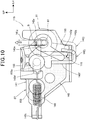
- Fig. 10 is an operation diagram illustrating the operation of the seat lock device 115.
- Fig. 9A the striker 97 of the rear seat 57 (see Fig. 4 ) is inserted into the slit 141g of the first bracket 141, and the locking pawl 142e of the second bracket 142 is located above the striker 97. Furthermore, the turning arm 118 of the key cylinder 91 is engaged with the engagement portion 142j of the second bracket 142. Therefore, the turning arm 118 is unturnable unless the key is inserted into the key cylinder 91. That is, in Fig. 9A , the seat lock device 115 is locked, and therefore the rear seat 57 cannot be opened.
- the L-shaped end portion 142g of the front extension portion 142b contacts with the turning arm 118 because the engagement portion 142j of the second bracket 142 is engaged with the turning arm 118. Therefore, the L-shaped end portion 142g is formed to surround the turning arm 118, thereby regulating the rightward movement of the second bracket 142 to prevent the seat lock device 115 from being released.
- the second bracket 142 When the key is kept inserted into the key cylinder 91 after the rear seat 57 is opened, the second bracket 142 is moved leftwardly by an elastic force of the tension coil spring 143 while turning the turning arm 118 by the extension portion main body 142f, and is returned to a position where the locking pawl 142e overlaps with the slit 141g in the forward-rearward direction.
- the locking pawl 142e is moved rightwardly once, and then returned leftwardly to be moved above the striker 97.
- the seat lock device 115 returns again to the locked state.
- the second bracket 142 is held at the position.
- the rear seat 57 is reclined forwardly to insert the striker 97 in the slit 141g, and then while maintaining the state, the key is inserted into the key cylinder 91 and turned counterclockwise.
- the locking pawl 142e is moved to the position which overlaps with the slit 141g in the forward-rearward direction to result in the locked state.
- the key cylinder 91 includes the turning arm 118 which is turned by the key operation
- the seat lock mechanism 87 includes the first bracket 141 which is fixed to the vehicle body frame 10A, and the second bracket 142 which is slidably supported on the first bracket 141 and engageable with the rear seat 57 side, the second bracket 142 is slid by being pressed by the turning arm 118, and the L-shaped end portion 142g serving as a slide regulating portion formed on the second bracket 142 regulates the second bracket 142 from being slid when the turning arm 118 is unturnable
- the L-shaped end portion 142g is provided to the second bracket 142, thereby preventing the second bracket 142 from being forcibly slid without the key. Accordingly, the seat lock mechanism 87 can be downsized as compared to a case where the guard member for preventing tampering with the second bracket 142 is provided to a peripheral part of the seat lock mechanism 87. Cables for connecting the key cylinder and the seat lock mechanism are not required unlike before, thereby reducing the cost and improving the assemblability.
- the seat lock mechanism 87 which is user-friendly.
- the number of ribs for restricting tampering with the seat lock mechanism 87 can be reduced when the ribs are provided to an exterior part, for example. Thereby, the cost can be reduced, and a split surface of the exterior part can be provided to the periphery of the seat lock mechanism 87. Accordingly, the degree of freedom of arrangement of the exterior part can be increased, and the appearance can be improved.
- the article storage part 85 for storing articles is formed below the rear seat 57, and the seat lock mechanism 87 is provided in the article storage part 85. Therefore, the storage space of the article storage part 85 can be increased by downsizing the seat lock mechanism 87, thereby improving the usability.
- the article storage part 85 which spreads downward and rearward of the seat lock mechanism 87 has a configuration in which articles such as the tool box 111 and the U-shaped lock member 112 can be easily taken in and out from the article storage part 85, thereby improving the usability of the article storage part 85.
- the key cylinder 91 and the seat lock mechanism 87 are disposed so as to be at least partially overlapped with each other in the forward-rearward direction, thereby enabling the occupied spaces of the key cylinder 91 and the seat lock mechanism 87 to be reduced in the forward-rearward direction, and increasing the volume of the article storage part 85, particularly, the volume of the storage space rearward of the seat lock mechanism 87.
- the L-shaped end portion 142g is disposed below the key cylinder 91, thereby enabling the second bracket 142 to be easily slid horizontally when the turning arm 118 is turned, and simplifying the engagement structure of the second bracket 142 with the rear seat 57 side which is opened and closed up and down (i.e., the engagement structure of the striker 97 and the locking pawl 142e).
- the striker 97 is provided at a lower portion of the rear seat 57, the slit 141g into which the striker 97 is inserted is formed in the first bracket 141, and the locking pawl 142e which is disposed close to one side of the slit 141g and is engageable with the striker 97 inserted into the slit 141g is formed in the second bracket 142, so that the locking pawl 142e is disposed between the key cylinder 91 and the slit 141g.
- the locking pawl 142e is disposed between the key cylinder 91 and the slit 141g to cover the locking pawl 142e by the key cylinder 91 and the first bracket 141 in which the slit 141g is formed, thereby preventing the tampering with the locking pawl 142e.
- the seat lock device 115 is provided only in the rear seat 57 as illustrated in Fig. 3 , but without being limited to the rear seat 57, the seat lock device 115 may be provided only in the main seat 17, or in both of the main seat 17 and the rear seat 57.
Landscapes
- Engineering & Computer Science (AREA)
- Mechanical Engineering (AREA)
- Lock And Its Accessories (AREA)
- Seats For Vehicles (AREA)
Abstract
Description
- The present invention relates to a seat lock structure for a saddle riding vehicle in which a seat lock mechanism is directly operated by a key cylinder.
- There has been known a structure in which a seat lock mechanism is connected to a key cylinder by a cable, the key cylinder being adapted to lock and unlock the seat lock mechanism by a key operation, and a guard body for preventing access to a cable is provided to a bracket supporting the key cylinder (for example, see Patent Literature 1).
- Also, there has been known a structure formed so that a rear center cover covers a seat lock mechanism to guard the seat lock mechanism (for example, see Patent Literature 2).
-
- Patent Literature 1: Japanese Patent Laid-Open No.
2007-62561 - Patent Literature 2: Japanese Patent Laid-Open No.
2010-36596 - In
Patent Literature 1 and Patent Literature 2, the theft prevention is performed by covering a seat lock mechanism with a peripheral part or an external part of the seat lock mechanism, but this causes enlargement of a structure around the seat lock mechanism. The volume of the storage space provided under the seat is therefore restricted. - It is an object of the present invention to provide a seat lock structure for a saddle riding vehicle which can be downsized.
- To solve the above problem, the present invention provides a seat lock structure for a saddle riding vehicle, including a seat (17, 57) on which a rider or a passenger sits, a key cylinder (91), and a seat lock mechanism (87) to open and close the seat (17, 57) by a key operation of the key cylinder (91), in which the key cylinder (91) includes a turning arm (118) which is turned by the key operation, the seat lock mechanism (87) includes a first bracket (141) which is fixed to a vehicle body frame (10A), and a second bracket (142) which is slidably supported on the first bracket (141) and engageable with a seat (17, 57) side, and the second bracket (142) is slid by being pressed by the turning arm (118), and a slide regulating portion (142g) formed on the second bracket (142) regulates the second bracket (142) from being slid when the turning arm (118) is unturnable.
- In the above configuration, an article storage part (85) for storing articles may be formed below the seat (17, 57), and the seat lock mechanism (87) may be provided in the article storage part (85).
- In the above configuration, the article storage part (85) may be configured to spread downward and rearward of the seat lock mechanism (87).
- In the above configuration, the key cylinder (91) and the seat lock mechanism (87) may be disposed so as to be at least partially overlapped with each other in a forward-rearward direction.
- In the above configuration, the slide regulating portion (142g) may be disposed at a lower portion of the key cylinder (91).
- In the above configuration, a striker (97) may be provided below the seat (17, 57), a slit (141g) into which the striker (97) is inserted may be formed in the first bracket (141), and a locking pawl (142e) which is disposed close to one side of the slit (141g) and is engageable with the striker (97) inserted into the slit (141g) may be formed in the second bracket (142), so that the locking pawl (142e) is disposed between the key cylinder (91) and the slit (141g).
- A key cylinder of the present invention includes a turning arm which is turned by a key operation, a seat lock mechanism includes a first bracket which is fixed to a vehicle body frame, and a second bracket which is slidably supported on the first bracket and engageable with a seat side, the second bracket is slid by being pressed by the turning arm, and a slide regulating portion formed on the second bracket regulates the second bracket from being slid when the turning arm is unturnable. Therefore, the second bracket can be prevented from being forcibly slid without the key by providing the slide regulating portion on the second bracket. Thus, the seat lock mechanism can be downsized as compared to a case where a guard member for preventing tampering with the second bracket is provided to a peripheral part of the seat lock mechanism.
- An article storage part for storing articles is formed below a seat, and the seat lock mechanism is provided in the article storage part. Therefore, the storage space of the article storage part can be increased by downsizing the seat lock mechanism, thereby improving the usability.
- The article storage part which spreads downward and rearward of the seat lock mechanism has a configuration in which articles such as a tool box and a U-shaped lock member can be easily taken in and out from the article storage part, thereby improving the usability of the article storage part.
- The key cylinder and the seat lock mechanism are disposed so as to be at least partially overlapped with each other in the forward-rearward direction, thereby enabling occupied spaces of the key cylinder and the seat lock mechanism to be reduced in the forward-rearward direction, and increasing a volume of the article storage part.
- The slide regulating portion is disposed below the key cylinder, thereby enabling the second bracket to be easily slid horizontally when the turning arm is turned, and simplifying an engagement structure of the second bracket with the seat side which is opened and closed up and down.
- A striker is provided below the seat, a slit into which the striker is inserted is formed in the first bracket, and a locking pawl which is disposed close to one side of the slit and is engageable with the striker inserted into the slit is formed in the second bracket, so that the locking pawl is disposed between the key cylinder and the slit. Therefore, the locking pawl is disposed between the key cylinder and the slit, thereby preventing the tampering with the locking pawl.
-
- [
Fig. 1] Fig. 1 is a right side elevational view of a motorcycle provided with a seat lock mechanism according to the present invention. - [
Fig. 2] Fig. 2 is a perspective view illustrating a seat lock device of a rear seat and its surrounding. - [
Fig. 3] Fig. 3 is a right side sectional view in which a rear portion of the motorcycle is cut along a center line in a vehicle width direction, and a sectional view cut along line III-III ofFig 6 . - [
Fig. 4] Fig. 4 is a left side sectional view in which the rear portion of themotorcycle 10 is cut along the center line in the vehicle width direction, and a sectional view cut along line IV-IV ofFig 6 . - [
Fig. 5] Fig. 5 is a side sectional view illustrating the key cylinder. - [
Fig. 6] Fig. 6 is a plan view illustrating a vehicle body rear portion with the rear seat removed. - [
Fig. 7] Fig. 7 is a sectional view taken along line VII-VII ofFig 1 . - [
Fig. 8] Fig. 8 is a perspective view illustrating the seat lock mechanism. - [
Figs. 9A and 9B] Figs. 9A and 9B each are an explanatory view for describing the seat lock mechanism,Fig. 9A is an elevation view of the seat lock mechanism, and -
Fig. 9B is a left side elevational view of the seat lock mechanism. - [
Fig. 10] Fig. 10 is an operation diagram illustrating the operation of the seat lock device. - One embodiment of the present invention will be described below with reference to the drawings. Note that in the following description, directions such as forward, rearward, leftward, rightward, upward and downward directions are the same as those with respect to a vehicle body, unless otherwise specified. In addition, a sign "FR" in each drawing represents a forward direction of the vehicle body, a sign "UP" represents an upward direction of the vehicle body, and a sign "LH" represents a leftward direction of the vehicle body.
-
Fig. 1 is a right side elevational view of amotorcycle 10 provided with a seat lock mechanism according to the present invention. - The
motorcycle 10 is a saddle riding vehicle in which afront wheel 13 is supported on a front end portion of avehicle body frame 10A through afront fork 12, arear wheel 16 is supported on a lower portion of thevehicle body frame 10A through aswing arm 14, and amain seat 17 for a rider is supported on an upper portion of thevehicle body frame 10A. - The
vehicle body frame 10A includes: ahead pipe 10b; a pair of left and rightmain frames 10c; a pair of left andright pivot frames 10d; adown frame 10e; a pair of left andright seat frames 10f (seeFig. 7 ); and a pair of left andright sub frames 10g. - The
head pipe 10b steerably supports thefront fork 12. The left and rightmain frames 10c extend obliquely rearwardly and downwardly from thehead pipe 10b. Thepivot frames 10d extend substantially downwardly from rear ends of themain frames 10c. Thedown frame 10e extends substantially downwardly from thehead pipe 10b. Theseat frames 10f extend obliquely rearwardly and upwardly from upper end portions of thepivot frames 10d to support themain seat 17. Thesub frames 10g extend obliquely rearwardly and upwardly from upper portions of thepivot frames 10d and in lower sides of theseat frames 10f so as to be connected to rear portions of theseat frames 10f. - The
front fork 12 is attached at an upper portion thereof with abar steering handle 21, and supports at a lower portion thereof thefront wheel 13 through awheel shaft 22. A front end portion of theswing arm 14 is swingably supported on apivot shaft 23 which is provided to the left andright pivot frames 10d, and a rear end portion of theswing arm 14 supports therear wheel 16 through awheel shaft 24. - An
engine 26 is supported on a center portion of thevehicle body frame 10A, and transmits power to therear wheel 16 through achain 28 from atransmission 27 integrally provided with theengine 26. Afuel tank 29 is supported on the left and rightmain frames 10c above theengine 26. Atank pad 65 is provided to a rear portion of thefuel tank 29. The pivot frames 10d and the downframe 10e support theengine 26. - The
engine 26 includes acrankcase 26a in which a crankshaft is rotatably housed, and acylinder part 26b rising obliquely upwardly and forwardly from an upper portion at a front of thecrankcase 26a. Anintake device 36 is connected to a rear portion of thecylinder part 26b. Theintake device 36 includes an aircleaner box 37, and anintake duct 38 which is connected to a rear portion of theair cleaner box 37. Anexhaust device 39 is connected to a front portion of thecylinder part 26b. - The
motorcycle 10 is covered by avehicle body cover 31. Thevehicle body cover 31 includes afront cowl 32, a pair of left and right side cowls 33, and a pair of left and right rear side body covers 34. - The
front cowl 32 includes anupper cowl 41, a pair of left and rightmiddle cowls 42, and a pair of left and rightlower cowls 43. - The
upper cowl 41 includes a centerupper cowl 45 which forms a front surface of thefront cowl 32, and is located at a center in a vehicle width direction and in a lower portion of theupper cowl 41, and a pair of left and right sideupper cowls 46 which are located outside the vehicle width direction, and awindscreen 47 is mounted on the left and right sideupper cowls 46. Aheadlight 51 is disposed below the sideupper cowls 46. - The
middle cowls 42 form left and right side surfaces of thefront cowl 32, and each of themiddle cowls 42 covers a front portion of the vehicle body to a position lower than thewheel shaft 22 of thefront wheel 13 from a side of the vehicle body. Each of thelower cowls 43 extends to the side of the lower portion of theengine 26 from the front end portion of thelower cowl 43 which is connected to the lower end portion of themiddle cowl 42. - The
side cowl 33 consists of a substantially V-shapedinner side cowl 54, and an inverse triangular-shapedouter side cowl 55 which covers the outside of the upper portion of theinner side cowl 54. Theside cowl 33 covers the lower portions of themain seat 17 and thefuel tank 29 from the side of the vehicle body. - The rear side body cover 34 covers, from the side of the vehicle body, a lower side of a side edge portion of each of a rear portion of the
main seat 17 for a rider, and arear seat 57 for a passenger which is disposed at a rear of themain seat 17. - The
air cleaner box 37 and theintake duct 38 are disposed inside theside cowl 33 in the vehicle width direction, particularly theintake duct 38 is disposed inside a rear portion of theinner side cowl 54 in the vehicle width direction. - A
reference numeral 61 in the figure represents a front fender which covers thefront wheel 13 from above, areference numeral 62 represents a pair of left and right rearview mirrors which are mounted on the sideupper cowls 46, respectively, and areference numeral 63 represents a pair of left and right front winkers which are mounted on front and upper portions of themiddle cowls 42, respectively. Areference numeral 64 represents a pair of left and right steps for a rider, areference numeral 66 represents a pair of left and right plate members which are attached to side surfaces in the lower portions of the pivot frames 10d, respectively, areference numeral 67 represents a rear fender which covers therear wheel 16 from above, areference numeral 69 represents a side stand which is attached to a lower end portion of theleft pivot frame 10d, areference numeral 73 represents a pair of left and right rear winkers which are mounted on therear fender 67, andreference numerals exhaust device 39. -
Fig. 2 is a perspective view illustrating a seat lock device 115 (seeFig. 3 ) of therear seat 57 and its surrounding. - A
center cowl 81 is provided at the rear of themain seat 17 so as to connect front ends at upper portions of respective left and right rear side body covers 34. Arear center cowl 82 is provided at the rear of therear seat 57 so as to connect upper edges at the rear end portions of respective left and right rear side body covers 34. - An article storage part 85 (see
Fig. 3 ) is formed in a space surrounded by the left and right rear side body covers 34, thecenter cowl 81 and therear center cowl 82 which are described above. An opening 86 (seeFig. 6 ) formed by the left and right rear side body covers 34, thecenter cowl 81 and therear center cowl 82, that is, theopening 86 above thearticle storage part 85 is covered by therear seat 57. - The
rear seat 57 is configured to be detachable and attachable from/to the vehicle body, and is locked by theseat lock device 115 provided in thearticle storage part 85. Acircular hole 81a is opened in a center of thecenter cowl 81 in the vehicle width direction, and akey cylinder 91 constituting theseat lock device 115 is disposed inside thecircular hole 81a. -
Fig. 3 is a right side sectional view in which a rear portion of themotorcycle 10 is cut along a center line in the vehicle width direction.Fig. 4 is a left side sectional view in which the rear portion of themotorcycle 10 is cut along the center line in the vehicle width direction. - As illustrated in
Fig. 3 , abridge member 93 which extends in the vehicle width direction is attached to the left and right seat frames 10f, and theseat lock device 115 is provided to thebridge member 93. Thekey cylinder 91 and aseat lock mechanism 87 constituting theseat lock device 115 are disposed in thearticle storage part 85. Thearticle storage part 85 extends downwardly and rearwardly of theseat lock device 115. The above-describedbridge member 93 is a component of thevehicle body frame 10A (seeFig. 1 ). - The
rear seat 57 includes aseat cushion member 95 having elasticity, and abottom plate 96 which is provided on a bottom surface of theseat cushion member 95. Thebottom plate 96 is integrally formed at a rear portion thereof with ahook 96a which protrudes downwardly and rearwardly, and is provided at a front portion thereof with a substantiallyU-shaped striker 97 which protrudes downwardly. - The
hook 96a is engaged with arear engaging part 98a of arear bracket 98 provided between the left and right seat frames 10f, thestriker 97 is engaged with theseat lock device 115, and therear seat 57 is fixed to the vehicle body side in the locked state. - The
rear fender 67 is attached through afender stay 102 to a rear end portion of a rearlower cowl 101 which forms a bottom wall of thearticle storage part 85. Note that areference numeral 104 represents a wire harness which energizes the rear winkers 73 (seeFig. 1 ) and a license plate lamp for illuminating a license plate which is attached to therear fender 67. - The
article storage part 85 is surrounded by thecenter cowl 81 on a front side of thearticle storage part 85, therear center cowl 82 and atail lamp 105 disposed below therear center cowl 82 on a rear side of thearticle storage part 85, the rearlower cowl 101 on a lower side of thearticle storage part 85, therear seat 57 on an upper side of thearticle storage part 85, and the rear side body covers 34 on left and right sides of thearticle storage part 85. Thearticle storage part 85 houses at a front and lower portion thereof atool box 111 and aU-shaped lock member 112, and houses at a rear portion thereof an ETC in-vehicle unit 113. - As illustrated in
Fig. 4 , thebridge member 93 includes anupper wall 93a which extends in the vehicle width direction, and afront wall 93b which extends substantially downwardly from a front edge of theupper wall 93a. Thefront wall 93b is formed to extend along afront wall 81b of thecenter cowl 81. - The
upper wall 93a is attached with theseat lock mechanism 87 which is engaged with thestriker 97, thefront wall 93b is attached with thekey cylinder 91 disposed to face thecircular hole 81a in thecenter cowl 81. - The
key cylinder 91 and theseat lock mechanism 87 constitute theseat lock device 115. - The
seat lock mechanism 87 includes afirst bracket 141 which is attached to a lower surface of theupper wall 93a of thebridge member 93, and asecond bracket 142 which is slidably attached to thefirst bracket 141 to be engaged or unengaged with thestriker 97 of therear seat 57. - The
second bracket 142 is engaged with aturning arm 118 of thekey cylinder 91 to be slid to both sides in the vehicle width direction by turning of theturning arm 118. Note that areference numeral 135 represents an accessory socket provided in thearticle storage part 85. -
Fig. 5 is a sectional view illustrating thekey cylinder 91. - The
key cylinder 91 includes anouter cylinder 116, a turningmember 117 which is turnably inserted into theouter cylinder 116, and theturning arm 118 which is integrally provided to one end portion of the turningmember 117. - The
outer cylinder 116 includes amain body 121, and acylindrical member 122 which is fixed inside themain body 121. - The turning
member 117 includes akey insertion hole 117a into which a key is inserted, a plurality of axisorthogonal holes 117b which are opened in a direction orthogonal to an axis of the turningmember 117, andtumblers 124 each of which is inserted into the axisorthogonal hole 117b. Thetumblers 124 are moved in the axisorthogonal holes 117b when the key is inserted into thekey insertion hole 117a. Thus, thetumblers 124 are slid out of axis orthogonal holes (not illustrated) provided in thecylindrical member 122 of theouter cylinder 116, thereby enabling the turningmember 117 to be turnable with respect to thecylindrical member 122. When the key is pulled out from thekey insertion hole 117a, thetumblers 124 are inserted into both of the axisorthogonal holes 117b in the turningmember 117 and the axis orthogonal holes in thecylindrical member 122 so that the turningmember 117 is unturnable with respect to thecylindrical member 122. - One end surface of the
outer cylinder 116 is blocked by aplate 126, and the turningmember 117 extends to pass through theplate 126. - The turning
arm 118 is relatively unturnably supported on the turningmember 117, is disposed to be adjacent to theplate 126, and is held by a retainingring 127 provided to the turningmember 117. Acompression coil spring 131 is disposed between theplate 126 and astep portion 121a provided in an inner periphery surface of theouter cylinder 116. Thecompression coil spring 131 biases the turningmember 117 through theplate 126 and theturning arm 118 so that the turningmember 117 does not get out of theouter cylinder 116. Note that areference numeral 133 represents a cover member which blocks theouter cylinder 116 and a part of an end surface of the turningmember 117, thecover member 133 being provided with akey insertion opening 133a. -
Fig. 6 is a plan view illustrating a vehicle body rear portion with therear seat 57 removed. - The
bridge member 93, therear bracket 98, theU-shaped lock member 112, the ETC in-vehicle unit 113, and theaccessory socket 135 are exposed from theopening 86 of thearticle storage part 85 provided in the vehicle body rear portion. Astriker insertion hole 93c which is long in a forward-rearward direction of the vehicle body is opened in a center portion in the vehicle width direction of theupper wall 93a of thebridge member 93, in order to pass through the striker 97 (seeFig. 4 ). On theupper wall 93a of thebridge member 93, a mountingportion 81c of thecenter cowl 81 is attached by ascrew 145 to a left side of thestriker insertion hole 93c, and thefirst bracket 141 of theseat lock mechanism 87 is attached by abolt 146 to a right side of thestriker insertion hole 93c. - The
rear bracket 98 is formed in a U shape in a top plan view so as to have therear engaging part 98a in the rear portion of therear bracket 98. Thescrew 145 and thebolt 146 are covered by therear seat 57, and therefore such fixing members are not exposed to outside, thereby improving the appearance. -
Fig. 7 is a sectional view taken along line VII-VII ofFig. 1 . - The substantially inverted
U-shaped bridge member 93 is provided between the left and right seat frames 10f, 10f, and thekey cylinder 91 and theseat lock mechanism 87 are supported on an upper portion of thebridge member 93. Thekey cylinder 91 is located at a center in the vehicle width direction of the vehicle body rear portion. As described above, the substantially invertedU-shaped bridge member 93 enables theseat lock mechanism 87 to be located below theupper wall 93a of thebridge member 93, and a volume of thearticle storage part 85 to be secured. - The rear
lower cowl 101 has a curved sectional shape so that the center portion in the vehicle width direction is higher than outside the vehicle width direction, and is integrally formed with a pair of left andright side walls lower cowl 101. - A
U-shaped lock member 112 is disposed inside the left andright side walls tool box 111 is disposed in the upper portion of the left andright side walls - A pair of left and
right louvers bridge member 93 in the vehicle width direction. Thelouver 151 is a member for introducing outside air into thevehicle body cover 31, and the introduced outside air is supplied to theengine 26 through theintake duct 38 and theair cleaner box 37 illustrated inFig. 1 . Note that areference numeral 152 is a rear cross member provided between the left and right sub frames 10g, 10g which serves as a component of thevehicle body frame 10A (seeFig. 1 ). -
Fig. 8 is a perspective view illustrating theseat lock mechanism 87. - The
seat lock mechanism 87 includes thefirst bracket 141 which is attached to the bridge member 93 (seeFig. 4 ), the second bracket 142 (a part indicated by a plurality of dots; the same shall apply hereinafter) which is attached to thefirst bracket 141 so as to be movable in a vehicle lateral direction (vehicle width direction), and atension coil spring 143 provided between thefirst bracket 141 and thesecond bracket 142 to bias thesecond bracket 142 toward an engaging side with striker 97 (seeFig. 4 ). - The
first bracket 141 is integrally formed of a forward-descendingattachment portion 141a which is attached to thebridge member 93, arear wall 141b which extends substantially downwardly from a rear edge of theattachment portion 141a, a lower endbent portion 141c which is bent forwardly from a lower edge of therear wall 141b, and an L-shapedbent portion 141d which continuously extends to the rear portion of theattachment portion 141a and extends forwardly and downwardly from a right upper edge portion of therear wall 141b. - The
attachment portion 141a includes abolt insertion hole 141e for passing the bolt 146 (seeFig. 6 ) for fastening to thebridge member 93, and apositioning protrusion 141f which is provided to protrude upwardly at a front of thebolt insertion hole 141e. Thepositioning protrusion 141f is fitted in a protrusion insertion hole (not illustrated) which is opened to thebridge member 93. When thepositioning protrusion 141f is fitted in the protrusion insertion hole, theseat lock mechanism 87 is prevented from being turned with respect to thebridge member 93. - A
nut 153 into which thebolt 146 is screwed is attached to a bottom surface of theattachment portion 141a, and a female thread of thenut 153 matches thebolt insertion hole 141e. - The
rear wall 141b has a verticallylong slit 141g into which thestriker 97 is inserted (seeFig. 4 ). - The
second bracket 142 is integrally formed of avertical wall 142a which slides with therear wall 141b of thefirst bracket 141, afront extension portion 142b which extends forwardly from the lower portion of thevertical wall 142a, a rightbent portion 142c which is bent forwardly from a right edge of thevertical wall 142a, and a lockingpawl 142e which protrudes to the side from a left edge of thevertical wall 142a. - The
vertical wall 142a includes a pair ofoblong holes 142d into which holdingmembers 155 that are attached to therear wall 141b of thefirst bracket 141 are inserted. - The
front extension portion 142b includes a longitudinally placed planar extension portionmain body 142f, and an L-shapedend portion 142g which is formed to extend leftwardly and upwardly from a lower portion of a distal end of the extension portionmain body 142f. - The right
bent portion 142c has a springend insertion hole 142h opened to insert one end of thetension coil spring 143. Both ends of thetension coil spring 143 are hooked on the L-shapedbent portion 141d of thefirst bracket 141 and the rightbent portion 142c, respectively. - The locking
pawl 142e overlaps with theslit 141g of thefirst bracket 141 in the forward-rearward direction when being moved in the leftward direction, but does not overlap with theslit 141g when being moved in the rightward direction. InFig. 8 , thesecond bracket 142 is moved in the leftward direction with respect to thefirst bracket 141 by a tensile force of thetension coil spring 143, and the lockingpawl 142e overlaps with theslit 141g in the forward-rearward direction. -
Figs. 9A and 9B each are an explanatory view for describing theseat lock mechanism 87.Fig. 9A is an elevation view of theseat lock mechanism 87, andFig. 9B is a left side elevational view of theseat lock mechanism 87. - As illustrated in
Fig. 9A , the L-shapedbent portion 141d of thefirst bracket 141 includes aspring hooking portion 141p which hooks thetension coil spring 143 and extends vertically. A spring hookingrecess portion 141j for hooking the end portion of thetension coil spring 143 is formed in a lower portion of aside end surface 141h of thespring hooking portion 141p. - The
slit 141g of thefirst bracket 141 consists of a taperedportion 141k which is formed so that a width in the vehicle width direction of the taperedportion 141k is gradually reduced as it goes downwardly, and astraight portion 141m which extends downwardly so that the width in the vehicle width direction becomes substantially uniform from a lower end of the taperedportion 141k. Such a shape of theslit 141g enables thestriker 97 to be easily inserted into theslit 141g from above. - The holding
member 155 is integrally formed of ashaft portion 155a which is attached to therear wall 141b of thefirst bracket 141, and is inserted intooblong holes 142d of thesecond bracket 142, and aflange 155b which is formed larger than an outer diameter of theshaft portion 155a at an end portion of theshaft portion 155a. - A front end portion of the extension portion
main body 142f of thefront extension portion 142b and the L-shapedend portion 142g constitute anengagement portion 142j having a substantially U-shape or a substantially inverted J-shape in a front view where theturning arm 118 of thekey cylinder 91 enters to be engaged therewith. - The engagement between the turning
arm 118 and theengagement portion 142j is not disengaged in all ranges where thesecond bracket 142 is slid by turning of theturning arm 118. - The locking
pawl 142e of thesecond bracket 142 is formed so that a lower edge has a substantially horizontal flat surface, and is located above thestriker 97 which is inserted into theslit 141g of thefirst bracket 141, thereby preventing thestriker 97 from being moved upwardly. - Disposing the
engagement portion 142j of thesecond bracket 142 below thekey cylinder 91 enables thesecond bracket 142 to be easily slid horizontally when theturning arm 118 is swung. - As illustrated in
Fig. 9B , in thefirst bracket 141, theattachment portion 141a inclines downwardly toward the front, and therear wall 141b inclines forwardly. In thesecond bracket 142, thevertical wall 142a inclines forwardly, and thefront extension portion 142b inclines downwardly toward the front. - The
key cylinder 91 and theseat lock mechanism 87 are disposed so that partial portions of them (between a rear end portion of thekey cylinder 91 and a front end portion of theattachment portion 141a of theseat lock mechanism 87, and between the rear end portion of thekey cylinder 91 and a front end portion of thefront extension portion 142b) are overlapped with each other in the forward-rearward direction, and thekey cylinder 91 is disposed forward of the locking pawl (seeFig. 9A ) of thesecond bracket 142. - An
axial line 91a of the key cylinder 91 (for more details, theaxial line 91a of the turning member 117 (seeFig. 5 )) inclines upwardly toward the front, and theturning arm 118 of thekey cylinder 91 extends along theengagement portion 142j of thesecond bracket 142. - The holding
member 155 has afemale thread 155c formed in theshaft portion 155a, and a hexagonsocket head bolt 157 which is inserted into thebolt insertion hole 141n formed in therear wall 141b of thefirst bracket 141 is screwed in thefemale thread 155c of theshaft portion 155a to attach the holdingmember 155 to therear wall 141b. - The
spring hooking portion 141p of the L-shapedbent portion 141d in thefirst bracket 141 is formed substantially parallel to therear wall 141b, and overlaps with the rightbent portion 142c of thesecond bracket 142 in a side view. - Each of the
first bracket 141 and thesecond bracket 142 is formed by bending a sheet of plate, and thesecond bracket 142 has a plate thickness thicker than thefirst bracket 141. - The operation of the
seat lock device 115 described above will be described as follows. -
Fig. 10 is an operation diagram illustrating the operation of theseat lock device 115. - In
Fig. 9A , thestriker 97 of the rear seat 57 (seeFig. 4 ) is inserted into theslit 141g of thefirst bracket 141, and the lockingpawl 142e of thesecond bracket 142 is located above thestriker 97. Furthermore, the turningarm 118 of thekey cylinder 91 is engaged with theengagement portion 142j of thesecond bracket 142. Therefore, the turningarm 118 is unturnable unless the key is inserted into thekey cylinder 91. That is, inFig. 9A , theseat lock device 115 is locked, and therefore therear seat 57 cannot be opened. - In this state, when the
rear seat 57 is tried to be forcibly opened with a bar-like member or the like without using a key to move thesecond bracket 142 rightwardly, the L-shapedend portion 142g of thefront extension portion 142b contacts with the turningarm 118 because theengagement portion 142j of thesecond bracket 142 is engaged with the turningarm 118. Therefore, the L-shapedend portion 142g is formed to surround theturning arm 118, thereby regulating the rightward movement of thesecond bracket 142 to prevent theseat lock device 115 from being released. - When the key is inserted into the
key cylinder 91 to turn the turning member 117 (seeFig. 5 ) and theturning arm 118 in a direction indicated by an arrow A as illustrated inFig. 10 in a state where the above-described rear seat 57 (seeFig. 4 ) is locked, a distal end portion of theturning arm 118 presses the extension portionmain body 142f of thesecond bracket 142 rightwardly. As a result, thesecond bracket 142 slides rightwardly with respect to thefirst bracket 141 as indicated by an arrow B. That is, the lockingpawl 142e of thesecond bracket 142 is moved to a position which does not overlap with theslit 141g of thefirst bracket 141 in the forward-rearward direction. Thus, thestriker 97 whose upper movement is regulated by the lockingpawl 142e can be moved upwardly, thereby enabling therear seat 57 to be opened. - When the key is kept inserted into the
key cylinder 91 after therear seat 57 is opened, thesecond bracket 142 is moved leftwardly by an elastic force of thetension coil spring 143 while turning theturning arm 118 by the extension portionmain body 142f, and is returned to a position where the lockingpawl 142e overlaps with theslit 141g in the forward-rearward direction. In this state, when therear seat 57 is closed and thestriker 97 is inserted into theslit 141g, the lockingpawl 142e is moved rightwardly once, and then returned leftwardly to be moved above thestriker 97. In this state, when the key is extracted from thekey cylinder 91, theseat lock device 115 returns again to the locked state. - When the key is extracted from the
key cylinder 91 after therear seat 57 is opened, a movement position of thesecond bracket 142 and a turning position of theturning arm 118 are held in the state at that time. - For example, (1) when the key is extracted in a state where the
second bracket 142 is moved rightwardly and the lockingpawl 142e does not overlap with theslit 141g in the forward-rearward direction, thesecond bracket 142 is held at the position. Thus, in order to close therear seat 57, therear seat 57 is reclined forwardly to insert thestriker 97 in theslit 141g, and then while maintaining the state, the key is inserted into thekey cylinder 91 and turned counterclockwise. Thereby, the lockingpawl 142e is moved to the position which overlaps with theslit 141g in the forward-rearward direction to result in the locked state. -
- (2) When the key is extracted in a state where the
second bracket 142 is moved leftwardly and the lockingpawl 142e overlaps with theslit 141g in the forward-rearward direction, thesecond bracket 142 is held at the position, and in order to close therear seat 57, therear seat 57 is reclined forwardly, and thestriker 97 contacts an upper edge of the lockingpawl 142e. In this state, when the key is inserted into thekey cylinder 91 and turned clockwise, the lockingpawl 142e can be moved rightwardly, and therear seat 57 is completely closed to dispose thestriker 97 below the lockingpawl 142e to result in the locked state. - As described above, in order to lock the
rear seat 57, it is necessary to surely insert the key into thekey cylinder 91 before therear seat 57 is completely closed as described in the above (1) and (2), thereby preventing therear seat 57 from being locked in a state where the key is placed in the article storage part 85 (seeFig. 4 ). - As illustrated in
Fig. 1 ,Fig. 4 , andFigs. 9A, 9B , in the seat lock structure for themotorcycle 10 serving as a saddle riding vehicle which is provided with arear seat 57 serving as a seat on which a rider sits or a seat on which a passenger sits, akey cylinder 91, and aseat lock mechanism 87 to open and close therear seat 57 by the key operation of thekey cylinder 91, thekey cylinder 91 includes theturning arm 118 which is turned by the key operation, theseat lock mechanism 87 includes thefirst bracket 141 which is fixed to thevehicle body frame 10A, and thesecond bracket 142 which is slidably supported on thefirst bracket 141 and engageable with therear seat 57 side, thesecond bracket 142 is slid by being pressed by the turningarm 118, and the L-shapedend portion 142g serving as a slide regulating portion formed on thesecond bracket 142 regulates thesecond bracket 142 from being slid when theturning arm 118 is unturnable. With this configuration, the L-shapedend portion 142g is provided to thesecond bracket 142, thereby preventing thesecond bracket 142 from being forcibly slid without the key. Accordingly, theseat lock mechanism 87 can be downsized as compared to a case where the guard member for preventing tampering with thesecond bracket 142 is provided to a peripheral part of theseat lock mechanism 87. Cables for connecting the key cylinder and the seat lock mechanism are not required unlike before, thereby reducing the cost and improving the assemblability. - When closing the
rear seat 57, it is necessary to insert the key into thekey cylinder 91 to turn theturning arm 118, thereby preventing the seat from being locked in the state where the key is placed in thearticle storage part 85 below therear seat 57. Accordingly, there is provided theseat lock mechanism 87 which is user-friendly. - Since it is not necessary to provide the guard member to the periphery parts of the
seat lock mechanism 87, the number of ribs for restricting tampering with theseat lock mechanism 87 can be reduced when the ribs are provided to an exterior part, for example. Thereby, the cost can be reduced, and a split surface of the exterior part can be provided to the periphery of theseat lock mechanism 87. Accordingly, the degree of freedom of arrangement of the exterior part can be increased, and the appearance can be improved. - As illustrated in
Fig. 3 andFig. 4 , thearticle storage part 85 for storing articles is formed below therear seat 57, and theseat lock mechanism 87 is provided in thearticle storage part 85. Therefore, the storage space of thearticle storage part 85 can be increased by downsizing theseat lock mechanism 87, thereby improving the usability. - The
article storage part 85 which spreads downward and rearward of theseat lock mechanism 87 has a configuration in which articles such as thetool box 111 and theU-shaped lock member 112 can be easily taken in and out from thearticle storage part 85, thereby improving the usability of thearticle storage part 85. - As illustrated in
Fig. 4 , thekey cylinder 91 and theseat lock mechanism 87 are disposed so as to be at least partially overlapped with each other in the forward-rearward direction, thereby enabling the occupied spaces of thekey cylinder 91 and theseat lock mechanism 87 to be reduced in the forward-rearward direction, and increasing the volume of thearticle storage part 85, particularly, the volume of the storage space rearward of theseat lock mechanism 87. - As illustrated in
Fig. 8 andFig. 9A , the L-shapedend portion 142g is disposed below thekey cylinder 91, thereby enabling thesecond bracket 142 to be easily slid horizontally when theturning arm 118 is turned, and simplifying the engagement structure of thesecond bracket 142 with therear seat 57 side which is opened and closed up and down (i.e., the engagement structure of thestriker 97 and the lockingpawl 142e). - As illustrated in
Fig. 4 andFigs. 9A, 9B , thestriker 97 is provided at a lower portion of therear seat 57, theslit 141g into which thestriker 97 is inserted is formed in thefirst bracket 141, and the lockingpawl 142e which is disposed close to one side of theslit 141g and is engageable with thestriker 97 inserted into theslit 141g is formed in thesecond bracket 142, so that the lockingpawl 142e is disposed between thekey cylinder 91 and theslit 141g. Therefore, the lockingpawl 142e is disposed between thekey cylinder 91 and theslit 141g to cover thelocking pawl 142e by thekey cylinder 91 and thefirst bracket 141 in which theslit 141g is formed, thereby preventing the tampering with the lockingpawl 142e. - The above-described embodiment is only for purposes of illustrating one aspect of the present invention, and can be arbitrarily modified and applied without departing from the scope of the present invention.
- For example, in the above-described embodiment, the
seat lock device 115 is provided only in therear seat 57 as illustrated inFig. 3 , but without being limited to therear seat 57, theseat lock device 115 may be provided only in themain seat 17, or in both of themain seat 17 and therear seat 57. -
- 10
- Motorcycle (saddle riding vehicle)
- 10A
- Vehicle body frame
- 17
- Main seat (seat)
- 57
- Rear seat (seat)
- 85
- Article storage part
- 87
- Seat lock mechanism
- 91
- Key cylinder
- 97
- Striker
- 115
- Seat lock device
- 118
- Turning arm
- 141
- First bracket
- 141g
- Slit
- 142
- Second bracket
- 142e
- Locking pawl
- 142g
- L-shaped end portion (slide regulating portion)
Claims (6)
- A seat lock structure for a saddle riding vehicle, comprising:a seat (17, 57) on which a rider or a passenger sits;a key cylinder (91); anda seat lock mechanism (87) to open and close the seat (17, 57) by a key operation of the key cylinder (91), whereinthe key cylinder (91) includes a turning arm (118) which is turned by a key operation,the seat lock mechanism (87) includes a first bracket (141) which is fixed to a vehicle body frame (10A), and a second bracket (142) which is slidably supported on the first bracket (141) and engageable with a seat (17, 57) side, andthe second bracket (142) is slid by being pressed by the turning arm (118), and a slide regulating portion (142g) formed on the second bracket (142) regulates the second bracket (142) from being slid when the turning arm (118) is unturnable.
- The seat lock structure for a saddle riding vehicle according to claim 1, wherein
an article storage part (85) for storing articles is formed below the seat (17, 57), and the seat lock mechanism (87) is provided in the article storage part (85). - The seat lock structure for a saddle riding vehicle according to claim 2, wherein
the article storage part (85) spreads downward and rearward of the seat lock mechanism (87). - The seat lock structure for a saddle riding vehicle according to any one of claims 1 to 3, wherein
the key cylinder (91) and the seat lock mechanism (87) are disposed so as to be at least partially overlapped with each other in a forward-rearward direction. - The seat lock structure for a saddle riding vehicle according to any one of claims 1 to 4, wherein
the slide regulating portion (142g) is disposed below the key cylinder (91). - The seat lock structure for a saddle riding vehicle according to any one of claims 1 to 5, wherein
a striker (97) is provided at a lower portion of the seat (17, 57), a slit (141g) into which the striker (97) is inserted is formed in the first bracket (141), and a locking pawl (142e) which is disposed close to one side of the slit (141g) and is engageable with the striker (97) inserted into the slit (141g) is formed in the second bracket (142), so that the locking pawl (142e) is disposed between the key cylinder (91) and the slit (141g).
Applications Claiming Priority (1)
| Application Number | Priority Date | Filing Date | Title |
|---|---|---|---|
| PCT/JP2015/062589 WO2016170688A1 (en) | 2015-04-24 | 2015-04-24 | Seat lock structure for saddle riding vehicle |
Publications (3)
| Publication Number | Publication Date |
|---|---|
| EP3287348A1 true EP3287348A1 (en) | 2018-02-28 |
| EP3287348A4 EP3287348A4 (en) | 2018-05-02 |
| EP3287348B1 EP3287348B1 (en) | 2020-03-18 |
Family
ID=57142976
Family Applications (1)
| Application Number | Title | Priority Date | Filing Date |
|---|---|---|---|
| EP15889927.8A Active EP3287348B1 (en) | 2015-04-24 | 2015-04-24 | Seat lock structure for saddle riding vehicle |
Country Status (7)
| Country | Link |
|---|---|
| US (1) | US10221593B2 (en) |
| EP (1) | EP3287348B1 (en) |
| JP (1) | JP6389327B2 (en) |
| CN (1) | CN107531300B (en) |
| BR (1) | BR112017021359B1 (en) |
| TW (1) | TWI627339B (en) |
| WO (1) | WO2016170688A1 (en) |
Cited By (1)
| Publication number | Priority date | Publication date | Assignee | Title |
|---|---|---|---|---|
| US10221593B2 (en) * | 2015-04-24 | 2019-03-05 | Honda Motor Co., Ltd. | Seat lock structure for saddle riding vehicle |
Families Citing this family (8)
| Publication number | Priority date | Publication date | Assignee | Title |
|---|---|---|---|---|
| JP6502297B2 (en) * | 2016-09-30 | 2019-04-17 | 本田技研工業株式会社 | Saddle-ride type vehicle |
| JP2018083530A (en) * | 2016-11-24 | 2018-05-31 | 本田技研工業株式会社 | Lock structure of saddle-riding type vehicle |
| JP6799516B2 (en) * | 2017-09-25 | 2020-12-16 | 本田技研工業株式会社 | Lock device |
| JP6892526B2 (en) * | 2018-01-31 | 2021-06-23 | 本田技研工業株式会社 | Saddle-type vehicle |
| JP7024474B2 (en) * | 2018-02-08 | 2022-02-24 | スズキ株式会社 | Motorcycle frame structure |
| JP7024475B2 (en) * | 2018-02-08 | 2022-02-24 | スズキ株式会社 | Motorcycle frame structure |
| JP2022089641A (en) | 2020-12-04 | 2022-06-16 | ヤマハ発動機株式会社 | Saddle-riding type vehicle |
| WO2025125924A1 (en) * | 2023-12-14 | 2025-06-19 | Pelliscase, Lda | Passenger seat for motorcycles with storage |
Family Cites Families (18)
| Publication number | Priority date | Publication date | Assignee | Title |
|---|---|---|---|---|
| JPS5218811Y2 (en) * | 1973-09-08 | 1977-04-28 | ||
| JPS5189624A (en) * | 1975-01-31 | 1976-08-05 | Rotsukusochino enkakuseigyosochi | |
| JPS52148660U (en) * | 1976-05-07 | 1977-11-11 | ||
| US4157844A (en) * | 1977-11-28 | 1979-06-12 | General Motors Corporation | Tailgate lock and control assembly |
| JPS59110290U (en) * | 1983-01-12 | 1984-07-25 | 本田技研工業株式会社 | Seat lock mechanism in vehicles such as motorcycles |
| US6237710B1 (en) * | 1998-10-26 | 2001-05-29 | Yamaha Hatsudoki Kabushiki Kaisha | Locking arrangement for motorcycle |
| JP4394776B2 (en) * | 1999-09-06 | 2010-01-06 | 本田技研工業株式会社 | Seat lock structure for motorcycles |
| JP3816290B2 (en) * | 2000-02-29 | 2006-08-30 | 本田技研工業株式会社 | Scooter type seat mounting structure |
| WO2003004338A1 (en) * | 2001-07-02 | 2003-01-16 | Honda Giken Kogyo Kabushiki Kaisha | Seat lock device for autobicycles |
| TWI253423B (en) * | 2004-03-17 | 2006-04-21 | Honda Motor Co Ltd | Longitudinally slidable seat structure for two- or three-wheeled vehicle |
| JP4694315B2 (en) | 2005-08-31 | 2011-06-08 | 川崎重工業株式会社 | Seat lock guard structure |
| TW200927573A (en) * | 2007-12-19 | 2009-07-01 | Kwang Yang Motor Co | Motorcycle saddle lock |
| JP5258437B2 (en) | 2008-07-31 | 2013-08-07 | 本田技研工業株式会社 | Anti-theft structure |
| JP2012025273A (en) * | 2010-07-23 | 2012-02-09 | Honda Motor Co Ltd | Rear structure of saddle riding type vehicle |
| JP2013103566A (en) * | 2011-11-11 | 2013-05-30 | Suzuki Motor Corp | Straddle-type vehicle |
| JP5924990B2 (en) * | 2012-03-09 | 2016-05-25 | 本田技研工業株式会社 | Locking mechanism for saddle riding type vehicles |
| JP2014189104A (en) * | 2013-03-26 | 2014-10-06 | Yamaha Motor Co Ltd | Motorcycle |
| EP3287348B1 (en) * | 2015-04-24 | 2020-03-18 | Honda Motor Co., Ltd. | Seat lock structure for saddle riding vehicle |
-
2015
- 2015-04-24 EP EP15889927.8A patent/EP3287348B1/en active Active
- 2015-04-24 JP JP2017513940A patent/JP6389327B2/en active Active
- 2015-04-24 BR BR112017021359-1A patent/BR112017021359B1/en active IP Right Grant
- 2015-04-24 CN CN201580078941.XA patent/CN107531300B/en active Active
- 2015-04-24 WO PCT/JP2015/062589 patent/WO2016170688A1/en not_active Ceased
- 2015-04-24 US US15/565,342 patent/US10221593B2/en active Active
-
2016
- 2016-04-14 TW TW105111675A patent/TWI627339B/en not_active IP Right Cessation
Cited By (1)
| Publication number | Priority date | Publication date | Assignee | Title |
|---|---|---|---|---|
| US10221593B2 (en) * | 2015-04-24 | 2019-03-05 | Honda Motor Co., Ltd. | Seat lock structure for saddle riding vehicle |
Also Published As
| Publication number | Publication date |
|---|---|
| CN107531300A (en) | 2018-01-02 |
| US10221593B2 (en) | 2019-03-05 |
| JP6389327B2 (en) | 2018-09-19 |
| WO2016170688A1 (en) | 2016-10-27 |
| EP3287348A4 (en) | 2018-05-02 |
| BR112017021359A2 (en) | 2018-06-26 |
| TWI627339B (en) | 2018-06-21 |
| EP3287348B1 (en) | 2020-03-18 |
| BR112017021359B1 (en) | 2022-10-04 |
| TW201704613A (en) | 2017-02-01 |
| CN107531300B (en) | 2019-12-10 |
| US20180073285A1 (en) | 2018-03-15 |
| JPWO2016170688A1 (en) | 2018-02-15 |
Similar Documents
| Publication | Publication Date | Title |
|---|---|---|
| EP3287348B1 (en) | Seat lock structure for saddle riding vehicle | |
| US7448663B2 (en) | Guard structure for vehicle seat lock | |
| JP6145310B2 (en) | Motorcycle exhaust pipe side cover | |
| EP3251932B1 (en) | Straddled vehicle | |
| EP2933174B1 (en) | Saddled vehicle | |
| JP5021191B2 (en) | Electrical component removal prevention structure | |
| US12286182B2 (en) | Straddled vehicle | |
| JP5806483B2 (en) | Vehicle with cowl | |
| US9863461B2 (en) | Cable guard structure for locking mechanism of vehicle, and vehicle including same | |
| JP2014061840A (en) | Saddle-riding type vehicle | |
| JP2013133075A (en) | Seat storage structure for saddle-ride type vehicles | |
| CN103129649B (en) | Vehicle light assembly for saddle-ride type vehicle | |
| JP5352383B2 (en) | Rear structure of motorcycle | |
| CN102285395B (en) | Saddle type vehicle | |
| JP4641467B2 (en) | Rear structure of motorcycle | |
| JP6053477B2 (en) | Motorcycle rear flap stay | |
| CN222329892U (en) | Saddle-type vehicle | |
| CN110121459B (en) | Seat lock structure of saddle-riding vehicle | |
| JP2023018456A (en) | saddle-riding vehicle | |
| OA18290A (en) | ||
| JP2020050307A (en) | Vehicle lock device |
Legal Events
| Date | Code | Title | Description |
|---|---|---|---|
| STAA | Information on the status of an ep patent application or granted ep patent |
Free format text: STATUS: THE INTERNATIONAL PUBLICATION HAS BEEN MADE |
|
| PUAI | Public reference made under article 153(3) epc to a published international application that has entered the european phase |
Free format text: ORIGINAL CODE: 0009012 |
|
| STAA | Information on the status of an ep patent application or granted ep patent |
Free format text: STATUS: REQUEST FOR EXAMINATION WAS MADE |
|
| 17P | Request for examination filed |
Effective date: 20171010 |
|
| AK | Designated contracting states |
Kind code of ref document: A1 Designated state(s): AL AT BE BG CH CY CZ DE DK EE ES FI FR GB GR HR HU IE IS IT LI LT LU LV MC MK MT NL NO PL PT RO RS SE SI SK SM TR |
|
| AX | Request for extension of the european patent |
Extension state: BA ME |
|
| A4 | Supplementary search report drawn up and despatched |
Effective date: 20180406 |
|
| RIC1 | Information provided on ipc code assigned before grant |
Ipc: B62K 11/04 20060101ALI20180329BHEP Ipc: B62J 1/12 20060101AFI20180329BHEP Ipc: E05B 83/00 20140101ALI20180329BHEP |
|
| DAV | Request for validation of the european patent (deleted) | ||
| DAX | Request for extension of the european patent (deleted) | ||
| STAA | Information on the status of an ep patent application or granted ep patent |
Free format text: STATUS: EXAMINATION IS IN PROGRESS |
|
| 17Q | First examination report despatched |
Effective date: 20190221 |
|
| GRAP | Despatch of communication of intention to grant a patent |
Free format text: ORIGINAL CODE: EPIDOSNIGR1 |
|
| STAA | Information on the status of an ep patent application or granted ep patent |
Free format text: STATUS: GRANT OF PATENT IS INTENDED |
|
| INTG | Intention to grant announced |
Effective date: 20191014 |
|
| GRAS | Grant fee paid |
Free format text: ORIGINAL CODE: EPIDOSNIGR3 |
|
| GRAA | (expected) grant |
Free format text: ORIGINAL CODE: 0009210 |
|
| STAA | Information on the status of an ep patent application or granted ep patent |
Free format text: STATUS: THE PATENT HAS BEEN GRANTED |
|
| AK | Designated contracting states |
Kind code of ref document: B1 Designated state(s): AL AT BE BG CH CY CZ DE DK EE ES FI FR GB GR HR HU IE IS IT LI LT LU LV MC MK MT NL NO PL PT RO RS SE SI SK SM TR |
|
| REG | Reference to a national code |
Ref country code: GB Ref legal event code: FG4D |
|
| REG | Reference to a national code |
Ref country code: DE Ref legal event code: R096 Ref document number: 602015049213 Country of ref document: DE |
|
| REG | Reference to a national code |
Ref country code: AT Ref legal event code: REF Ref document number: 1245605 Country of ref document: AT Kind code of ref document: T Effective date: 20200415 Ref country code: IE Ref legal event code: FG4D |
|
| PG25 | Lapsed in a contracting state [announced via postgrant information from national office to epo] |
Ref country code: RS Free format text: LAPSE BECAUSE OF FAILURE TO SUBMIT A TRANSLATION OF THE DESCRIPTION OR TO PAY THE FEE WITHIN THE PRESCRIBED TIME-LIMIT Effective date: 20200318 Ref country code: FI Free format text: LAPSE BECAUSE OF FAILURE TO SUBMIT A TRANSLATION OF THE DESCRIPTION OR TO PAY THE FEE WITHIN THE PRESCRIBED TIME-LIMIT Effective date: 20200318 Ref country code: NO Free format text: LAPSE BECAUSE OF FAILURE TO SUBMIT A TRANSLATION OF THE DESCRIPTION OR TO PAY THE FEE WITHIN THE PRESCRIBED TIME-LIMIT Effective date: 20200618 |
|
| REG | Reference to a national code |
Ref country code: NL Ref legal event code: MP Effective date: 20200318 |
|
| PG25 | Lapsed in a contracting state [announced via postgrant information from national office to epo] |
Ref country code: SE Free format text: LAPSE BECAUSE OF FAILURE TO SUBMIT A TRANSLATION OF THE DESCRIPTION OR TO PAY THE FEE WITHIN THE PRESCRIBED TIME-LIMIT Effective date: 20200318 Ref country code: LV Free format text: LAPSE BECAUSE OF FAILURE TO SUBMIT A TRANSLATION OF THE DESCRIPTION OR TO PAY THE FEE WITHIN THE PRESCRIBED TIME-LIMIT Effective date: 20200318 Ref country code: HR Free format text: LAPSE BECAUSE OF FAILURE TO SUBMIT A TRANSLATION OF THE DESCRIPTION OR TO PAY THE FEE WITHIN THE PRESCRIBED TIME-LIMIT Effective date: 20200318 Ref country code: GR Free format text: LAPSE BECAUSE OF FAILURE TO SUBMIT A TRANSLATION OF THE DESCRIPTION OR TO PAY THE FEE WITHIN THE PRESCRIBED TIME-LIMIT Effective date: 20200619 Ref country code: BG Free format text: LAPSE BECAUSE OF FAILURE TO SUBMIT A TRANSLATION OF THE DESCRIPTION OR TO PAY THE FEE WITHIN THE PRESCRIBED TIME-LIMIT Effective date: 20200618 |
|
| REG | Reference to a national code |
Ref country code: LT Ref legal event code: MG4D |
|
| PG25 | Lapsed in a contracting state [announced via postgrant information from national office to epo] |
Ref country code: NL Free format text: LAPSE BECAUSE OF FAILURE TO SUBMIT A TRANSLATION OF THE DESCRIPTION OR TO PAY THE FEE WITHIN THE PRESCRIBED TIME-LIMIT Effective date: 20200318 |
|
| PG25 | Lapsed in a contracting state [announced via postgrant information from national office to epo] |
Ref country code: RO Free format text: LAPSE BECAUSE OF FAILURE TO SUBMIT A TRANSLATION OF THE DESCRIPTION OR TO PAY THE FEE WITHIN THE PRESCRIBED TIME-LIMIT Effective date: 20200318 Ref country code: SK Free format text: LAPSE BECAUSE OF FAILURE TO SUBMIT A TRANSLATION OF THE DESCRIPTION OR TO PAY THE FEE WITHIN THE PRESCRIBED TIME-LIMIT Effective date: 20200318 Ref country code: IS Free format text: LAPSE BECAUSE OF FAILURE TO SUBMIT A TRANSLATION OF THE DESCRIPTION OR TO PAY THE FEE WITHIN THE PRESCRIBED TIME-LIMIT Effective date: 20200718 Ref country code: CZ Free format text: LAPSE BECAUSE OF FAILURE TO SUBMIT A TRANSLATION OF THE DESCRIPTION OR TO PAY THE FEE WITHIN THE PRESCRIBED TIME-LIMIT Effective date: 20200318 Ref country code: LT Free format text: LAPSE BECAUSE OF FAILURE TO SUBMIT A TRANSLATION OF THE DESCRIPTION OR TO PAY THE FEE WITHIN THE PRESCRIBED TIME-LIMIT Effective date: 20200318 Ref country code: SM Free format text: LAPSE BECAUSE OF FAILURE TO SUBMIT A TRANSLATION OF THE DESCRIPTION OR TO PAY THE FEE WITHIN THE PRESCRIBED TIME-LIMIT Effective date: 20200318 Ref country code: PT Free format text: LAPSE BECAUSE OF FAILURE TO SUBMIT A TRANSLATION OF THE DESCRIPTION OR TO PAY THE FEE WITHIN THE PRESCRIBED TIME-LIMIT Effective date: 20200812 Ref country code: EE Free format text: LAPSE BECAUSE OF FAILURE TO SUBMIT A TRANSLATION OF THE DESCRIPTION OR TO PAY THE FEE WITHIN THE PRESCRIBED TIME-LIMIT Effective date: 20200318 |
|
| REG | Reference to a national code |
Ref country code: AT Ref legal event code: MK05 Ref document number: 1245605 Country of ref document: AT Kind code of ref document: T Effective date: 20200318 |
|
| REG | Reference to a national code |
Ref country code: CH Ref legal event code: PL |
|
| REG | Reference to a national code |
Ref country code: DE Ref legal event code: R097 Ref document number: 602015049213 Country of ref document: DE |
|
| PG25 | Lapsed in a contracting state [announced via postgrant information from national office to epo] |
Ref country code: MC Free format text: LAPSE BECAUSE OF FAILURE TO SUBMIT A TRANSLATION OF THE DESCRIPTION OR TO PAY THE FEE WITHIN THE PRESCRIBED TIME-LIMIT Effective date: 20200318 |
|
| PLBE | No opposition filed within time limit |
Free format text: ORIGINAL CODE: 0009261 |
|
| STAA | Information on the status of an ep patent application or granted ep patent |
Free format text: STATUS: NO OPPOSITION FILED WITHIN TIME LIMIT |
|
| PG25 | Lapsed in a contracting state [announced via postgrant information from national office to epo] |
Ref country code: AT Free format text: LAPSE BECAUSE OF FAILURE TO SUBMIT A TRANSLATION OF THE DESCRIPTION OR TO PAY THE FEE WITHIN THE PRESCRIBED TIME-LIMIT Effective date: 20200318 Ref country code: CH Free format text: LAPSE BECAUSE OF NON-PAYMENT OF DUE FEES Effective date: 20200430 Ref country code: ES Free format text: LAPSE BECAUSE OF FAILURE TO SUBMIT A TRANSLATION OF THE DESCRIPTION OR TO PAY THE FEE WITHIN THE PRESCRIBED TIME-LIMIT Effective date: 20200318 Ref country code: DK Free format text: LAPSE BECAUSE OF FAILURE TO SUBMIT A TRANSLATION OF THE DESCRIPTION OR TO PAY THE FEE WITHIN THE PRESCRIBED TIME-LIMIT Effective date: 20200318 Ref country code: IT Free format text: LAPSE BECAUSE OF FAILURE TO SUBMIT A TRANSLATION OF THE DESCRIPTION OR TO PAY THE FEE WITHIN THE PRESCRIBED TIME-LIMIT Effective date: 20200318 Ref country code: LU Free format text: LAPSE BECAUSE OF NON-PAYMENT OF DUE FEES Effective date: 20200424 Ref country code: LI Free format text: LAPSE BECAUSE OF NON-PAYMENT OF DUE FEES Effective date: 20200430 |
|
| REG | Reference to a national code |
Ref country code: BE Ref legal event code: MM Effective date: 20200430 |
|
| 26N | No opposition filed |
Effective date: 20201221 |
|
| PG25 | Lapsed in a contracting state [announced via postgrant information from national office to epo] |
Ref country code: BE Free format text: LAPSE BECAUSE OF NON-PAYMENT OF DUE FEES Effective date: 20200430 Ref country code: PL Free format text: LAPSE BECAUSE OF FAILURE TO SUBMIT A TRANSLATION OF THE DESCRIPTION OR TO PAY THE FEE WITHIN THE PRESCRIBED TIME-LIMIT Effective date: 20200318 |
|
| GBPC | Gb: european patent ceased through non-payment of renewal fee |
Effective date: 20200618 |
|
| PG25 | Lapsed in a contracting state [announced via postgrant information from national office to epo] |
Ref country code: IE Free format text: LAPSE BECAUSE OF NON-PAYMENT OF DUE FEES Effective date: 20200424 Ref country code: GB Free format text: LAPSE BECAUSE OF NON-PAYMENT OF DUE FEES Effective date: 20200618 Ref country code: FR Free format text: LAPSE BECAUSE OF NON-PAYMENT OF DUE FEES Effective date: 20200518 |
|
| PG25 | Lapsed in a contracting state [announced via postgrant information from national office to epo] |
Ref country code: SI Free format text: LAPSE BECAUSE OF FAILURE TO SUBMIT A TRANSLATION OF THE DESCRIPTION OR TO PAY THE FEE WITHIN THE PRESCRIBED TIME-LIMIT Effective date: 20200318 |
|
| REG | Reference to a national code |
Ref country code: DE Ref legal event code: R084 Ref document number: 602015049213 Country of ref document: DE |
|
| PG25 | Lapsed in a contracting state [announced via postgrant information from national office to epo] |
Ref country code: TR Free format text: LAPSE BECAUSE OF FAILURE TO SUBMIT A TRANSLATION OF THE DESCRIPTION OR TO PAY THE FEE WITHIN THE PRESCRIBED TIME-LIMIT Effective date: 20200318 Ref country code: MT Free format text: LAPSE BECAUSE OF FAILURE TO SUBMIT A TRANSLATION OF THE DESCRIPTION OR TO PAY THE FEE WITHIN THE PRESCRIBED TIME-LIMIT Effective date: 20200318 Ref country code: CY Free format text: LAPSE BECAUSE OF FAILURE TO SUBMIT A TRANSLATION OF THE DESCRIPTION OR TO PAY THE FEE WITHIN THE PRESCRIBED TIME-LIMIT Effective date: 20200318 |
|
| PG25 | Lapsed in a contracting state [announced via postgrant information from national office to epo] |
Ref country code: MK Free format text: LAPSE BECAUSE OF FAILURE TO SUBMIT A TRANSLATION OF THE DESCRIPTION OR TO PAY THE FEE WITHIN THE PRESCRIBED TIME-LIMIT Effective date: 20200318 Ref country code: AL Free format text: LAPSE BECAUSE OF FAILURE TO SUBMIT A TRANSLATION OF THE DESCRIPTION OR TO PAY THE FEE WITHIN THE PRESCRIBED TIME-LIMIT Effective date: 20200318 |
|
| PGFP | Annual fee paid to national office [announced via postgrant information from national office to epo] |
Ref country code: DE Payment date: 20250319 Year of fee payment: 11 |