EP3287169A1 - In vivo - Google Patents
In vivo Download PDFInfo
- Publication number
- EP3287169A1 EP3287169A1 EP16783322.7A EP16783322A EP3287169A1 EP 3287169 A1 EP3287169 A1 EP 3287169A1 EP 16783322 A EP16783322 A EP 16783322A EP 3287169 A1 EP3287169 A1 EP 3287169A1
- Authority
- EP
- European Patent Office
- Prior art keywords
- vivo
- measuring device
- radiation
- dose measuring
- expansion
- Prior art date
- Legal status (The legal status is an assumption and is not a legal conclusion. Google has not performed a legal analysis and makes no representation as to the accuracy of the status listed.)
- Granted
Links
Images






Classifications
-
- A—HUMAN NECESSITIES
- A61—MEDICAL OR VETERINARY SCIENCE; HYGIENE
- A61N—ELECTROTHERAPY; MAGNETOTHERAPY; RADIATION THERAPY; ULTRASOUND THERAPY
- A61N5/00—Radiation therapy
- A61N5/10—X-ray therapy; Gamma-ray therapy; Particle-irradiation therapy
- A61N5/1048—Monitoring, verifying, controlling systems and methods
- A61N5/1071—Monitoring, verifying, controlling systems and methods for verifying the dose delivered by the treatment plan
-
- A—HUMAN NECESSITIES
- A61—MEDICAL OR VETERINARY SCIENCE; HYGIENE
- A61B—DIAGNOSIS; SURGERY; IDENTIFICATION
- A61B6/00—Apparatus or devices for radiation diagnosis; Apparatus or devices for radiation diagnosis combined with radiation therapy equipment
- A61B6/42—Arrangements for detecting radiation specially adapted for radiation diagnosis
- A61B6/4208—Arrangements for detecting radiation specially adapted for radiation diagnosis characterised by using a particular type of detector
- A61B6/425—Arrangements for detecting radiation specially adapted for radiation diagnosis characterised by using a particular type of detector using detectors specially adapted to be used in the interior of the body
-
- A—HUMAN NECESSITIES
- A61—MEDICAL OR VETERINARY SCIENCE; HYGIENE
- A61B—DIAGNOSIS; SURGERY; IDENTIFICATION
- A61B5/00—Measuring for diagnostic purposes; Identification of persons
- A61B5/68—Arrangements of detecting, measuring or recording means, e.g. sensors, in relation to patient
-
- A—HUMAN NECESSITIES
- A61—MEDICAL OR VETERINARY SCIENCE; HYGIENE
- A61M—DEVICES FOR INTRODUCING MEDIA INTO, OR ONTO, THE BODY; DEVICES FOR TRANSDUCING BODY MEDIA OR FOR TAKING MEDIA FROM THE BODY; DEVICES FOR PRODUCING OR ENDING SLEEP OR STUPOR
- A61M25/00—Catheters; Hollow probes
- A61M25/10—Balloon catheters
- A61M25/1002—Balloon catheters characterised by balloon shape
-
- A—HUMAN NECESSITIES
- A61—MEDICAL OR VETERINARY SCIENCE; HYGIENE
- A61B—DIAGNOSIS; SURGERY; IDENTIFICATION
- A61B17/00—Surgical instruments, devices or methods
- A61B2017/00017—Electrical control of surgical instruments
- A61B2017/00022—Sensing or detecting at the treatment site
-
- A—HUMAN NECESSITIES
- A61—MEDICAL OR VETERINARY SCIENCE; HYGIENE
- A61M—DEVICES FOR INTRODUCING MEDIA INTO, OR ONTO, THE BODY; DEVICES FOR TRANSDUCING BODY MEDIA OR FOR TAKING MEDIA FROM THE BODY; DEVICES FOR PRODUCING OR ENDING SLEEP OR STUPOR
- A61M25/00—Catheters; Hollow probes
- A61M25/10—Balloon catheters
- A61M2025/1043—Balloon catheters with special features or adapted for special applications
- A61M2025/1086—Balloon catheters with special features or adapted for special applications having a special balloon surface topography, e.g. pores, protuberances, spikes or grooves
-
- A—HUMAN NECESSITIES
- A61—MEDICAL OR VETERINARY SCIENCE; HYGIENE
- A61N—ELECTROTHERAPY; MAGNETOTHERAPY; RADIATION THERAPY; ULTRASOUND THERAPY
- A61N5/00—Radiation therapy
- A61N5/10—X-ray therapy; Gamma-ray therapy; Particle-irradiation therapy
- A61N5/1001—X-ray therapy; Gamma-ray therapy; Particle-irradiation therapy using radiation sources introduced into or applied onto the body; brachytherapy
- A61N5/1014—Intracavitary radiation therapy
Definitions
- the present invention relates to an in vivo radiation dose measuring device.
- radiation therapy treats cancer by using high-energy X-ray, gamma ray, electron beam, proton beam, carbon ion beam, or the like, to damage tumor cells and induce apoptosis. Therefore, in order to maximize the damage to tumor cells, as much radiation as possible needs to be delivered to tumors.
- radiation therapy affects not only tumors but also normal organs around the tumors. If a lot of radiation is irradiated to normal organs, side effects of radiation may occur.
- the dose of radiation delivered to normal organs should be accurately measured.
- the dose of radiation at one point was measured in the conventional art, it is not possible to predict the occurrence of side effects of radiation and it is difficult to find an exact relationship between the dose of radiation delivered and the side effect of radiation.
- An aspect of the present invention is to provide a technique for measuring an accurate two-dimensional dose distribution of radiation delivered to an in vivo tissue by radiation therapy on a cancer patient.
- the present invention provides an in vivo radiation dose measuring device, including: a main body extending long in a direction of in vivo insertion and being capable of supplying a fluid; an expansion part having at least a portion fixed or connected to the main body and being expandable and shrinkable by inflow and outflow of the fluid; and a radiation measurement part disposed on the expansion part to measure a plane(2-dimensional) dose distribution of radiation in the in vivo tissue which the expansion part expands to touch.
- the radiation measurement part may have a film type wrapping at least a portion of the expansion part, and the radiation measurement part may be unfolded upon the expansion of the expansion part, and returned to a form wrapping the expansion part prior to expansion upon the shrinkage of the expansion part.
- the radiation measurement part may have one or more fold lines parallel with the direction of insertion, the fold lines being formed in a direction in which the radiation measurement part wraps the expansion part.
- the in vivo radiation dose measuring device may further include an accommodation part accommodating the radiation measurement part, wherein the accommodation part is transformable in compliance with a shape change of the radiation measurement part.
- the accommodation part and the expansion part may be in contact with each other, and at least one of the accommodation part and the expansion part may be formed of or treated with a material for reducing frictional force therebetween.
- the accommodation part may have a pocket form and may be in close contact with the radiation measurement part.
- the accommodation part may be formed of an elastic material.
- the accommodation part may be formed of at least one of polyurethane, nylon, and polyester.
- the expansion part may be formed of at least one of silicone, polyurethane, nylon, natural rubber, and synthetic rubber.
- the expansion part may have a fixation element, and at least one of the radiation measurement part and the accommodation part may have a fixation counterpart correspondence to the fixation element.
- the fixation element may protrude outward, and the fixation counterpart may include at least one of a hole and a coupling structure, which are formed in the radiation measurement part.
- the in vivo radiation dose measuring device may further include a position indication part for allowing the understanding of an insertion position of the device from the outside upon the insertion of the device into the body.
- the in vivo radiation dose measuring device may further include a position indication part for allowing the understanding of an insertion position of the device from the outside upon the insertion of the device into the body, wherein the position indication part is positioned on the fixation element.
- the in vivo radiation dose measuring device may further include a shrinkage part formed outside the accommodation part, wherein the shrinkage part gives shrinking force to the radiation measurement part upon the shrinkage of the expansion part.
- the shrinkage part may be formed of an elastic material.
- the shrinkage part may be formed of at least one of polyurethane, nylon, polyester, silicone, natural rubber, and synthetic rubber.
- the accommodation part may include: a first portion wrapping the expansion part; and a second portion connected with the first portion to wrap the radiation measurement part, wherein the accommodation part gives shrinking force to the expansion part.
- the in vivo radiation dose measuring device may further include a shrinkage auxiliary part connected to a plurality of sites of the radiation measurement part, one end of the shrinkage auxiliary part protruding out of the body when the device is inserted into the body, wherein the shrinkage auxiliary part is capable of additionally shrinking the radiation measurement part by operating a portion protruding out of the body
- the shrinkage auxiliary part may shrink a portion of the radiation measurement part, which is close to the direction of in vivo insertion.
- the present invention provides an in vivo radiation dose measuring device, including: an extension part extending long in a direction of in vivo insertion and being capable of supplying a fluid to the outside; an expansion part having at least a portion fixed or connected to the extension part and being expandable and shrinkable by inflow and outflow of the fluid; and a radiation measurement part, which wraps at least a portion of the expansion part in an unfolded state upon the expansion of the expansion part and wraps the expansion part in an at least partly folded state upon of the shrinkage of the expansion part.
- the radiation measurement part may measure the radiation dose in the body tissue corresponding to the expansion part in the plane dimension.
- the radiation measurement part may be configured of a film, extend in the direction of insertion, and have one or more fold lines for determining the folded state.
- an in vivo radiation dose measuring device for measuring an accurate two-dimensional dose distribution of radiation delivered to an in vivo tissue.
- the in vivo radiation dose measuring device may be used for female genitalia, oral cavity, nasal cavity, pharynx, esophagus, bronchus, and the like.
- FIGS. 1 and 7 An in vivo radiation dose measuring device according to a first embodiment of the present invention and a use thereof will be described with reference to FIGS. 1 and 7 .
- FIG. 1 is a perspective view showing a shrunken state of an in vivo radiation dose measuring device according to a first embodiment of the present invention
- FIG. 2 is a cross-sectional view taken along line II-II' of FIG. 1
- FIG. 3 is a perspective view showing an expanded state of the in vivo radiation dose measuring device according to the first embodiment of the present invention
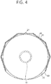
- FIG. 4 is a cross-sectional view taken along line IV-IV' of FIG. 3 .
- An in vivo radiation dose measuring device 1 is inserted into the body through the anus in a shrunken state as shown in FIG. 1 . Thereafter, the in vivo radiation dose measuring device expands as shown in FIG. 3 .
- the in vivo radiation dose measuring device 1 performs radiation treatment on the prostate or the like in an expanded state, and measures an accurate two-dimensional does distribution of radiation delivered to the in vivo tissue.
- the in vivo radiation dose measuring device 1 includes a main body 10, an expansion part 20, a radiation measurement part 30, an accommodation part 40, a position indication part 50, and a shrinkage part 60.
- the expansion part 20 has a balloon type, and expands by receiving a fluid, such as air or water, from the main body 10, and again shrinks when the fluid flows out through the main body 10.
- a fluid such as air or water
- the radiation measurement part 30 has a film type, and is accommodated in a pocket type accommodation part 40.
- a dosimeter using radiation sensitization including a radiation-sensitive film or the like, or a dosimeter using radiation ionization, including a diode array plate or the like, may be used.
- the radiation indication part 50 is accommodated in the expansion part 20, and formed of a material allowing the understanding of the position by an X-ray image.
- the position indication part 50 may be attached to another element or may be prepared as one body with another element.
- a portion of the radiation measurement part 30 is fixed to the expansion part 20, and the description thereof will be described later.
- the shrinkage part 60 wraps the accommodation part, and gives shrinking force to the accommodation unit 40.
- the in vivo radiation dose measurement device 1 when actually used, may be used by covering an outside of the shrinkage part 60 with a separate waterproof cover as needed.
- the radiation measurement part 30 wraps the entirety of the expansion part 20 in a polygonal shape, and a partial region of the expansion part 20 is wrapped by a plurality of layers.
- the radiation measurement part 30 maintains a form in which the radiation measurement 30 is in close contact with the expansion part 20 due to shrinking force.
- the radiation measurement part 30 wraps only a portion of the expansion part 20 in a polygonal shape, and wraps the entirety of the expansion part in a single layer type.
- the radiation measurement part 30 maintains a form in which the radiation measurement part 30 is in close contact with the expansion part 20 due to the shrinking force of the shrinkage part 60.
- FIG. 5 is a perspective view of an expansion part of the in vivo radiation dose measuring device according to the first embodiment of the present invention
- FIG. 6 is a cross-sectional view taken along line VI-VI' of FIG. 5
- FIG. 7 is a plane view of a radiation measurement part of the in vivo radiation dose measuring device according to the first embodiment of the present invention.
- the main body 10 includes a long tube-shaped main body tube 11 and a fluid supply tube 12.
- a fluid supply hole 13 connected to the expansion part 20 is formed in a middle region of the main body tube 11, and a mount groove 14 is formed into an end region of the main body tube 11.
- a gas outflow hole 15 for exhausting gas in the body is formed in an end portion of the main body tube 11 when the in vivo radiation dose measuring device is applied into the rectum.
- the gas outflow hole 15 becomes a passage for respiration of a patient when the in vivo radiation dose measuring device is applied into the oral cavity, nasal cavity, pharynx, bronchus, and the like.
- the fluid supply tube 12 supplies a fluid from an air or water supply source (not shown) to the expansion part 20 through the fluid supply hole 13.
- an opening/closing valve capable of controlling the supply and collection of the fluid through the fluid supply tube 12.
- the expansion part 20 is in close contact with the main body tube 11 at the time of shrinkage, and has a pair of fixation elements 21 protruding outward. In the expansion part 20 at the time of expansion, both ends are in close contact with the main body tube 11 to keep the airtightness and the middle region is inflated by the fluid. There is an accommodation space inside the fixation part 21, and the position indication part 50 is positioned in the accommodation space.
- the expansion part 20 may be formed of a silicone material, which may be silicone, polyurethane, nylon, natural rubber, or synthetic rubber alone or a composite thereof.
- the expansion part 20 expands and shrinks according to the supply and collection of the fluid.
- the position indication part 50 may be formed of any material that can be detected by an X-ray image, for example, a metal piece single material or a mixture of metal particles and a polymer.
- the position indication part 50 may be provided in a cylindrical shape in one embodiment, but may be provided in another shape, such as a spherical shape or a ring shape in another embodiment.
- the radiation measurement part 30 may be a dosimeter type radiation film using radiation sensitization, and may be configured of multiple layers including a protective layer - a radiation-sensitive layer - a protection layer.
- the radiation measurement part 30 is generally rectangular in shape.
- the radiation measurement part 30 has fold lines 31 formed at predetermined intervals and fixation counterparts 32 corresponding to the fixation elements 21 of the expanding part 20.
- the fold lines 31 are prepared through incisions in a length direction of the main body tube 11, and the fixation counterparts 32 are prepared in a hole type. A plurality of the fold lines 31 are formed in a direction in which the radiation measurement part 30 wraps the expansion part 20.
- the radiation measurement part 30 may further comprise a distance maintenance element, which connects both sides, which are divided by the fold lines 31, to prevent both sides from excessively being apart.
- the distance maintenance element may employ an adhesive tape, but is not limited thereto.
- the accommodation part 40 is formed in a pocket shape corresponding to the radiation measurement part 30, and a material for the accommodation part 40 may be a material having excellent shrinking force and restoring force.
- a specific example of the material may be polyurethane, nylon, and polyester alone or in a mixture thereof.
- the accommodation part 40 prevents the radiation measurement part 30 from being damaged by a direct contact with another component, especially, the expansion part 20, or from being affected by expanded and shrunken states through a contact with another component.
- At least one of the accommodation part 40 and the expansion part 20 may be formed of a material for reducing frictional force therebetween or may be surface-treated to surface treatment for friction prevention, and the surface treatment for friction prevention may be a coating treatment with an anti-friction agent, a protrusion treatment on a surface, surface modification, or the like.
- the shrinkage part 60 also has a pocket type, and one end portion of the shrinkage part 60 is mounted in the mount groove 14 of the main body.
- the shrinkage part 60 may also be formed of a material having excellent shrinking force and restoring force, and may be formed of polyurethane, silicone, natural rubber, synthetic rubber, polyurethane/nylon, or polyurethane/polyester.
- the in vivo radiation dose measuring device 1 in a shrunken state is inserted into the body through the anus of a prostatic cancer patient. After the insertion into the body, the in vivo radiation dose measuring device 1 is converted into an expanded state through the supply of a fluid.
- the position of the position indication part 50 is understood by using an X-ray image, and then the position of the entire in vivo radiation dose measuring device 1 is controlled.
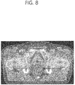
- FIG. 8 shows a state in which the in vivo radiation dose measuring device is inserted in the rectum through the anus in the radiation therapy of prostate cancer.
- the thick semicircular portion indicated by the arrow in the drawing is a radiation-sensitive film.
- the two-dimensional dose distribution of radiation delivered to the rectum of a patient by radiation therapy is measured by the radiation measurement part 30 in the form of a film.
- the radiation measurement part 30 maintains a shape of a non-overlapping single layer, so that the dose distribution can be measured over a very wide area.
- the radiation measurement part 30 is in close contact with the surrounding tissue due to the expansion, so that the radiation dose in the surrounding tissue can be accurately measured.
- the probability of occurrence of radiation side effects in normal organs is significantly increased if a limited dose of radiation or more radiation is delivered to a particular volume of each organ. Since the use of a conventional point dosimeter can actually obtain a dose value at only one point, the dose of radiation delivered to a particular volume is difficult to obtain. According to the present invention, the two-dimensional radiation dose distribution can be measured by the film-type radiation measurement part 30, and thus, so that such a conventional problem can be solved.
- the accurate position of the in vivo radiation dose measuring device 1 can be understood through the position indication part 50, and even when the treatment is repeatedly performed several times to several tens of times, the radiation measurement part 30 can be always positioned at the same site. Therefore, an accurate total dose distribution can be obtained through the dose distribution data that have been obtained from the measurements in the treatment procedure each time
- the in vivo radiation measuring device 1 After the end of the radiation treatment, the in vivo radiation measuring device 1 is made in a shrunken state by removing the fluid, and then the fluid is discharged out of the body.
- FIG. 9 is a plane view of a radiation measurement part of the in vivo radiation dose measuring device according to the second embodiment of the present invention.
- a radiation measurement part 30 according to the second embodiment has a film type as in the first embodiment, and has fold lines 31 formed by incisions.
- fixation counterparts 32 of the radiation measurement part 30 according to the second embodiment are formed to protrude outward.
- the radiation measurement part 30 may be variously modified other than the type in the second embodiment.
- the fold lines 31 may be formed by decreasing the thickness of the film instead of employing incisions, or by intermittent incisions. That is, the fold lines 31 may be formed by several methods as long as the radiation measurement part 30 can be easily folded.
- the radiation measurement part 30 may be prepared by connecting a plurality of band-shaped radiation films. Both ends of the fold line 31 may be treated in a linear or curved shape as in the first embodiment.
- the radiation measurement part 30 may be prepared without fold lines 31 as long as the radiation measurement part 30 is sufficiently thin so that a radiation detection layer inside is not damaged regardless of bending or winding.
- the radiation measurement part 30 wrap the expansion part 20 not in a polygonal shape, but in a shape corresponding to the expansion part 20 or in a circular or semicircular shape.
- FIG. 10 shows a radiation measurement part 30 and a shrinkage auxiliary part 70 of an in vivo radiation dose measuring device according to a third embodiment of the present invention
- FIG. 11 shows an operation state of the shrinkage auxiliary part in the in vivo radiation dose measuring device according to the third embodiment of the present invention.
- the shrinkage auxiliary part is not shown in FIG. 11 .
- the in vivo radiation dose measuring device is configured to solve a problem in that the radiation measurement part 30, which have been unfolded in the body due to the expansion of the expansion part 20, is not properly folded upon the shrinkage of the expansion part 20.
- a shrinkage auxiliary part 70 is prepared in a string type, and one end thereof is connected to an auxiliary hole 33 of the radiation measurement part 30.
- the auxiliary hole 33 connected to the shrinkage auxiliary part 70 is provided at a portion of the radiation measurement part 30, which is distant from the end portion of the main body 10 (in FIG. 5 , the portion at which the gas discharge hole 15 is located), that is, at a portion of the radiation measurement part 30, which is in first contact with the anus when the in vivo radiation dose measuring device is drawn out from the body.
- the other end of the shrinkage auxiliary part 70 is exposed to the outside through the main body tube 11, and to this end, a separate passage hole may be formed in the main body tube 11.
- the shrinkage auxiliary part 70 is prepared by having two disconnected portions (indicated by a solid line and dotted line, respectively). In another embodiment, the shrinkage auxiliary part 70 may have a wire type, or may be prepared in a single type.
- the end portion of the radiation measurement part 30 is compulsorily in close contact with the expansion part 20 by pulling the shrinkage auxiliary part 70 exposed to the outside.
- the medical staff can safely withdraw the in vivo radiation dose measuring device 1 out of the body while the end portion of the radiation measurement part 30 is in close contact with the expansion part to have a reduced diameter.
- FIG. 12 shows a shrunken state of an in vivo radiation dose measuring device according to a fourth embodiment of the present invention
- FIG. 13 shows an expanded state of the in vivo radiation dose measuring device according to the fourth embodiment of the present invention.
- FIGS. 12 and 13 show states corresponding to FIGS. 2 and 4 , respectively.
- a main body tube 11 and an expansion part 20 are not shown.
- a radiation measurement part 30 and an accommodation part 40 are shown apart from each other for convenience of explanation.
- the accommodation part 40 according to the fourth embodiment is composed of a first portion 40a forming a closed curve inside, a second portion 40b forming a closed curve outside, and a third portion 40c connecting the first portion 40a and the second portion 40b.
- the main body tube 11 and the expansion 20 are positioned at the first portion 40a, and the radiation measurement part 30 is positioned at the second portion 40b.
- the accommodation part 40 also performs a shrinking role while the shrinkage part 60 is omitted, unlike in the first embodiment.
- the accommodation part 40 of the radiation measurement part 30 is divided into two accommodation spaces by the third portion 40c.
- Such a division structure allows the radiation measurement part 30 to be smoothly folded at the time of shrinkage of the expansion part 20 such that the expansion part 20 and the radiation measurement part 30 interfere with each other, and can provide greater shrinking force compared with the first embodiment. Therefore, in the fourth embodiment, a separate shrinkage part 60 may be omitted.
Landscapes
- Health & Medical Sciences (AREA)
- Life Sciences & Earth Sciences (AREA)
- Engineering & Computer Science (AREA)
- Biomedical Technology (AREA)
- Veterinary Medicine (AREA)
- Public Health (AREA)
- General Health & Medical Sciences (AREA)
- Animal Behavior & Ethology (AREA)
- Heart & Thoracic Surgery (AREA)
- Pathology (AREA)
- Biophysics (AREA)
- Medical Informatics (AREA)
- Radiology & Medical Imaging (AREA)
- Nuclear Medicine, Radiotherapy & Molecular Imaging (AREA)
- Physics & Mathematics (AREA)
- Molecular Biology (AREA)
- Surgery (AREA)
- High Energy & Nuclear Physics (AREA)
- Optics & Photonics (AREA)
- Child & Adolescent Psychology (AREA)
- Pulmonology (AREA)
- Anesthesiology (AREA)
- Hematology (AREA)
- Measurement Of Radiation (AREA)
- Radiation-Therapy Devices (AREA)
Abstract
Description
- The present invention relates to an in vivo radiation dose measuring device.
- Generally, radiation therapy treats cancer by using high-energy X-ray, gamma ray, electron beam, proton beam, carbon ion beam, or the like, to damage tumor cells and induce apoptosis. Therefore, in order to maximize the damage to tumor cells, as much radiation as possible needs to be delivered to tumors.
- However, radiation therapy affects not only tumors but also normal organs around the tumors. If a lot of radiation is irradiated to normal organs, side effects of radiation may occur.
- Therefore, the dose of radiation delivered to normal organs should be accurately measured. However, since only the dose of radiation at one point was measured in the conventional art, it is not possible to predict the occurrence of side effects of radiation and it is difficult to find an exact relationship between the dose of radiation delivered and the side effect of radiation.
- An aspect of the present invention is to provide a technique for measuring an accurate two-dimensional dose distribution of radiation delivered to an in vivo tissue by radiation therapy on a cancer patient.
- In accordance with an aspect of the present invention, the present invention provides an in vivo radiation dose measuring device, including: a main body extending long in a direction of in vivo insertion and being capable of supplying a fluid; an expansion part having at least a portion fixed or connected to the main body and being expandable and shrinkable by inflow and outflow of the fluid; and a radiation measurement part disposed on the expansion part to measure a plane(2-dimensional) dose distribution of radiation in the in vivo tissue which the expansion part expands to touch.
- The radiation measurement part may have a film type wrapping at least a portion of the expansion part, and the radiation measurement part may be unfolded upon the expansion of the expansion part, and returned to a form wrapping the expansion part prior to expansion upon the shrinkage of the expansion part.
- The radiation measurement part may have one or more fold lines parallel with the direction of insertion, the fold lines being formed in a direction in which the radiation measurement part wraps the expansion part.
- The in vivo radiation dose measuring device may further include an accommodation part accommodating the radiation measurement part, wherein the accommodation part is transformable in compliance with a shape change of the radiation measurement part.
- The accommodation part and the expansion part may be in contact with each other, and at least one of the accommodation part and the expansion part may be formed of or treated with a material for reducing frictional force therebetween.
- The accommodation part may have a pocket form and may be in close contact with the radiation measurement part.
- The accommodation part may be formed of an elastic material.
- The accommodation part may be formed of at least one of polyurethane, nylon, and polyester.
- The expansion part may be formed of at least one of silicone, polyurethane, nylon, natural rubber, and synthetic rubber.
- The expansion part may have a fixation element, and at least one of the radiation measurement part and the accommodation part may have a fixation counterpart correspondence to the fixation element.
- The fixation element may protrude outward, and the fixation counterpart may include at least one of a hole and a coupling structure, which are formed in the radiation measurement part.
- The in vivo radiation dose measuring device may further include a position indication part for allowing the understanding of an insertion position of the device from the outside upon the insertion of the device into the body.
- The in vivo radiation dose measuring device may further include a position indication part for allowing the understanding of an insertion position of the device from the outside upon the insertion of the device into the body, wherein the position indication part is positioned on the fixation element.
- The in vivo radiation dose measuring device may further include a shrinkage part formed outside the accommodation part, wherein the shrinkage part gives shrinking force to the radiation measurement part upon the shrinkage of the expansion part.
- The shrinkage part may be formed of an elastic material.
- The shrinkage part may be formed of at least one of polyurethane, nylon, polyester, silicone, natural rubber, and synthetic rubber.
- The accommodation part may include: a first portion wrapping the expansion part; and a second portion connected with the first portion to wrap the radiation measurement part, wherein the accommodation part gives shrinking force to the expansion part.
- The in vivo radiation dose measuring device may further include a shrinkage auxiliary part connected to a plurality of sites of the radiation measurement part, one end of the shrinkage auxiliary part protruding out of the body when the device is inserted into the body, wherein the shrinkage auxiliary part is capable of additionally shrinking the radiation measurement part by operating a portion protruding out of the body
- The shrinkage auxiliary part may shrink a portion of the radiation measurement part, which is close to the direction of in vivo insertion.
- In accordance with an aspect of the present invention, the present invention provides an in vivo radiation dose measuring device, including: an extension part extending long in a direction of in vivo insertion and being capable of supplying a fluid to the outside; an expansion part having at least a portion fixed or connected to the extension part and being expandable and shrinkable by inflow and outflow of the fluid; and a radiation measurement part, which wraps at least a portion of the expansion part in an unfolded state upon the expansion of the expansion part and wraps the expansion part in an at least partly folded state upon of the shrinkage of the expansion part.
- The radiation measurement part may measure the radiation dose in the body tissue corresponding to the expansion part in the plane dimension.
- The radiation measurement part may be configured of a film, extend in the direction of insertion, and have one or more fold lines for determining the folded state.
- According to the present invention, provided is an in vivo radiation dose measuring device for measuring an accurate two-dimensional dose distribution of radiation delivered to an in vivo tissue.
-
-
FIG. 1 is a perspective view showing a shrunken state of an in vivo radiation dose measuring device according to a first embodiment of the present invention. -
FIG. 2 is a cross-sectional view taken along line II-II' ofFIG. 1 . -
FIG. 3 is a perspective view showing an expanded state of the in vivo radiation dose measuring device according to the first embodiment of the present invention. -
FIG. 4 is a cross-sectional view taken along line IV-IV' ofFIG. 3 . -
FIG. 5 is a perspective view of an expansion part of the in vivo radiation dose measuring device according to the first embodiment of the present invention. -
FIG. 6 is a cross-sectional view taken along line VI-VI' ofFIG. 5 . -
FIG. 7 is a plane view of a radiation measurement part of the in vivo radiation dose measuring device according to the first embodiment of the present invention. -
FIG. 8 is a computed tomography (CT) image showing a state in which the in vivo radiation dose measuring device according to the first embodiment of the present invention is actually inserted into the body. -
FIG. 9 is a plane view of a radiation measurement part of an in vivo radiation dose measuring device according to a second embodiment of the present invention. -
FIG. 10 shows a radiation measurement part and a shrinkage auxiliary part of an in vivo radiation dose measuring device according to a third embodiment of the present invention. -
FIG. 11 shows an operation state of the shrinkage auxiliary part in the in vivo radiation dose measuring device according to the third embodiment of the present invention. -
FIG. 12 shows a shrunken state of an in vivo radiation dose measuring device according to a fourth embodiment of the present invention. -
FIG. 13 shows an expanded state of the in vivo radiation dose measuring device according to the fourth embodiment of the present invention. - Hereinafter, the present invention will be described in detail with reference to accompanying drawings.
- The accompanying drawings correspond to merely an example shown to illustrate technical scope of the present invention more detail, and the scope of the present invention is not limited to the accompanying drawings.
- The following embodiments are described by exemplifying cases in which an in vivo radiation dose measuring device is inserted into the rectum, but the in vivo radiation dose measuring device according to the present invention, without the limitation to the rectum, may be used for female genitalia, oral cavity, nasal cavity, pharynx, esophagus, bronchus, and the like.
- An in vivo radiation dose measuring device according to a first embodiment of the present invention and a use thereof will be described with reference to
FIGS. 1 and7 . -
FIG. 1 is a perspective view showing a shrunken state of an in vivo radiation dose measuring device according to a first embodiment of the present invention;FIG. 2 is a cross-sectional view taken along line II-II' ofFIG. 1 ;FIG. 3 is a perspective view showing an expanded state of the in vivo radiation dose measuring device according to the first embodiment of the present invention; andFIG. 4 is a cross-sectional view taken along line IV-IV' ofFIG. 3 . - An in vivo radiation dose measuring
device 1 according to a first embodiment of the present invention is inserted into the body through the anus in a shrunken state as shown inFIG. 1 . Thereafter, the in vivo radiation dose measuring device expands as shown inFIG. 3 . The in vivo radiation dose measuringdevice 1 performs radiation treatment on the prostate or the like in an expanded state, and measures an accurate two-dimensional does distribution of radiation delivered to the in vivo tissue. - The in vivo radiation dose measuring
device 1 includes amain body 10, anexpansion part 20, aradiation measurement part 30, anaccommodation part 40, aposition indication part 50, and ashrinkage part 60. - The
expansion part 20 has a balloon type, and expands by receiving a fluid, such as air or water, from themain body 10, and again shrinks when the fluid flows out through themain body 10. - In the first embodiment, the
radiation measurement part 30 has a film type, and is accommodated in a pockettype accommodation part 40. As theradiation measurement part 30, a dosimeter using radiation sensitization, including a radiation-sensitive film or the like, or a dosimeter using radiation ionization, including a diode array plate or the like, may be used. - The
radiation indication part 50 is accommodated in theexpansion part 20, and formed of a material allowing the understanding of the position by an X-ray image. In another embodiment, theposition indication part 50 may be attached to another element or may be prepared as one body with another element. - A portion of the
radiation measurement part 30 is fixed to theexpansion part 20, and the description thereof will be described later. - The
shrinkage part 60 wraps the accommodation part, and gives shrinking force to theaccommodation unit 40. Although not shown, the in vivo radiationdose measurement device 1, when actually used, may be used by covering an outside of theshrinkage part 60 with a separate waterproof cover as needed. - As shown in
FIG. 2 , in a shrunken state, theradiation measurement part 30 wraps the entirety of theexpansion part 20 in a polygonal shape, and a partial region of theexpansion part 20 is wrapped by a plurality of layers. In a shrunken state, theradiation measurement part 30 maintains a form in which theradiation measurement 30 is in close contact with theexpansion part 20 due to shrinking force. - As shown in
FIG. 4 , in an expanded state, theradiation measurement part 30 wraps only a portion of theexpansion part 20 in a polygonal shape, and wraps the entirety of the expansion part in a single layer type. In addition, in an expended state, theradiation measurement part 30 maintains a form in which theradiation measurement part 30 is in close contact with theexpansion part 20 due to the shrinking force of theshrinkage part 60. - Hereinafter, the in vivo radiation
dose measuring device 1 according to the first embodiment will be described in more detail with reference toFIGS. 5 to 7 . -
FIG. 5 is a perspective view of an expansion part of the in vivo radiation dose measuring device according to the first embodiment of the present invention;FIG. 6 is a cross-sectional view taken along line VI-VI' ofFIG. 5 ; andFIG. 7 is a plane view of a radiation measurement part of the in vivo radiation dose measuring device according to the first embodiment of the present invention. - The
main body 10 includes a long tube-shapedmain body tube 11 and afluid supply tube 12. Afluid supply hole 13 connected to theexpansion part 20 is formed in a middle region of themain body tube 11, and amount groove 14 is formed into an end region of themain body tube 11. Agas outflow hole 15 for exhausting gas in the body is formed in an end portion of themain body tube 11 when the in vivo radiation dose measuring device is applied into the rectum. Thegas outflow hole 15 becomes a passage for respiration of a patient when the in vivo radiation dose measuring device is applied into the oral cavity, nasal cavity, pharynx, bronchus, and the like. - The
fluid supply tube 12 supplies a fluid from an air or water supply source (not shown) to theexpansion part 20 through thefluid supply hole 13. Although not shown, there may be an opening/closing valve capable of controlling the supply and collection of the fluid through thefluid supply tube 12. - The
expansion part 20 is in close contact with themain body tube 11 at the time of shrinkage, and has a pair offixation elements 21 protruding outward. In theexpansion part 20 at the time of expansion, both ends are in close contact with themain body tube 11 to keep the airtightness and the middle region is inflated by the fluid. There is an accommodation space inside thefixation part 21, and theposition indication part 50 is positioned in the accommodation space. - The
expansion part 20 may be formed of a silicone material, which may be silicone, polyurethane, nylon, natural rubber, or synthetic rubber alone or a composite thereof. Theexpansion part 20 expands and shrinks according to the supply and collection of the fluid. - The
position indication part 50 may be formed of any material that can be detected by an X-ray image, for example, a metal piece single material or a mixture of metal particles and a polymer. Theposition indication part 50 may be provided in a cylindrical shape in one embodiment, but may be provided in another shape, such as a spherical shape or a ring shape in another embodiment. - In the first embodiment, the
radiation measurement part 30 may be a dosimeter type radiation film using radiation sensitization, and may be configured of multiple layers including a protective layer - a radiation-sensitive layer - a protection layer. Theradiation measurement part 30 is generally rectangular in shape. Theradiation measurement part 30 hasfold lines 31 formed at predetermined intervals andfixation counterparts 32 corresponding to thefixation elements 21 of the expandingpart 20. - The fold lines 31 are prepared through incisions in a length direction of the
main body tube 11, and thefixation counterparts 32 are prepared in a hole type. A plurality of the fold lines 31 are formed in a direction in which theradiation measurement part 30 wraps theexpansion part 20. - Although not shown, the
radiation measurement part 30 may further comprise a distance maintenance element, which connects both sides, which are divided by the fold lines 31, to prevent both sides from excessively being apart. The distance maintenance element may employ an adhesive tape, but is not limited thereto. - The
accommodation part 40 is formed in a pocket shape corresponding to theradiation measurement part 30, and a material for theaccommodation part 40 may be a material having excellent shrinking force and restoring force. A specific example of the material may be polyurethane, nylon, and polyester alone or in a mixture thereof. Theaccommodation part 40 prevents theradiation measurement part 30 from being damaged by a direct contact with another component, especially, theexpansion part 20, or from being affected by expanded and shrunken states through a contact with another component. - At least one of the
accommodation part 40 and theexpansion part 20 may be formed of a material for reducing frictional force therebetween or may be surface-treated to surface treatment for friction prevention, and the surface treatment for friction prevention may be a coating treatment with an anti-friction agent, a protrusion treatment on a surface, surface modification, or the like. - The
shrinkage part 60 also has a pocket type, and one end portion of theshrinkage part 60 is mounted in themount groove 14 of the main body. Theshrinkage part 60 may also be formed of a material having excellent shrinking force and restoring force, and may be formed of polyurethane, silicone, natural rubber, synthetic rubber, polyurethane/nylon, or polyurethane/polyester. - Hereinafter, a use method and effects of the in vivo radiation
dose measuring device 1 according to the first embodiment of the present invention will be described. - The in vivo radiation
dose measuring device 1 in a shrunken state is inserted into the body through the anus of a prostatic cancer patient. After the insertion into the body, the in vivo radiationdose measuring device 1 is converted into an expanded state through the supply of a fluid. The position of theposition indication part 50 is understood by using an X-ray image, and then the position of the entire in vivo radiationdose measuring device 1 is controlled. - Thereafter, when the in vivo radiation
dose measuring device 1 is positioned at a desired site, the in vivo radiationdose measuring device 1 performs radiation treatment after the setup of a patient is completed. The expanded state suppresses the movement of the prostate and maintains the shape of the rectum constantly, thereby improving the accuracy of the treatment.FIG. 8 shows a state in which the in vivo radiation dose measuring device is inserted in the rectum through the anus in the radiation therapy of prostate cancer. The thick semicircular portion indicated by the arrow in the drawing is a radiation-sensitive film. - According to the present invention, the two-dimensional dose distribution of radiation delivered to the rectum of a patient by radiation therapy is measured by the
radiation measurement part 30 in the form of a film. In the expanded state, theradiation measurement part 30 maintains a shape of a non-overlapping single layer, so that the dose distribution can be measured over a very wide area. In addition, theradiation measurement part 30 is in close contact with the surrounding tissue due to the expansion, so that the radiation dose in the surrounding tissue can be accurately measured. - According to the statistical analysis of clinical patients, the probability of occurrence of radiation side effects in normal organs is significantly increased if a limited dose of radiation or more radiation is delivered to a particular volume of each organ. Since the use of a conventional point dosimeter can actually obtain a dose value at only one point, the dose of radiation delivered to a particular volume is difficult to obtain. According to the present invention, the two-dimensional radiation dose distribution can be measured by the film-type
radiation measurement part 30, and thus, so that such a conventional problem can be solved. - Also, according to the present invention, the accurate position of the in vivo radiation
dose measuring device 1 can be understood through theposition indication part 50, and even when the treatment is repeatedly performed several times to several tens of times, theradiation measurement part 30 can be always positioned at the same site. Therefore, an accurate total dose distribution can be obtained through the dose distribution data that have been obtained from the measurements in the treatment procedure each time - After the end of the radiation treatment, the in vivo
radiation measuring device 1 is made in a shrunken state by removing the fluid, and then the fluid is discharged out of the body. - Hereinafter, an in vivo radiation dose measuring device according to a second embodiment of the present invention will be described with reference to
FIG. 9. FIG. 9 is a plane view of a radiation measurement part of the in vivo radiation dose measuring device according to the second embodiment of the present invention. - A
radiation measurement part 30 according to the second embodiment has a film type as in the first embodiment, and hasfold lines 31 formed by incisions. - Meanwhile,
fixation counterparts 32 of theradiation measurement part 30 according to the second embodiment are formed to protrude outward. - The
radiation measurement part 30 may be variously modified other than the type in the second embodiment. For example, the fold lines 31 may be formed by decreasing the thickness of the film instead of employing incisions, or by intermittent incisions. That is, the fold lines 31 may be formed by several methods as long as theradiation measurement part 30 can be easily folded. In addition, theradiation measurement part 30 may be prepared by connecting a plurality of band-shaped radiation films. Both ends of thefold line 31 may be treated in a linear or curved shape as in the first embodiment. - Meanwhile, the
radiation measurement part 30 may be prepared withoutfold lines 31 as long as theradiation measurement part 30 is sufficiently thin so that a radiation detection layer inside is not damaged regardless of bending or winding. In this case, theradiation measurement part 30 wrap theexpansion part 20 not in a polygonal shape, but in a shape corresponding to theexpansion part 20 or in a circular or semicircular shape. - Hereinafter, an in vivo radiation dose measuring device according to a third embodiment of the present invention will be described with reference to
FIGS. 10 and11 . -
FIG. 10 shows aradiation measurement part 30 and a shrinkageauxiliary part 70 of an in vivo radiation dose measuring device according to a third embodiment of the present invention; andFIG. 11 shows an operation state of the shrinkage auxiliary part in the in vivo radiation dose measuring device according to the third embodiment of the present invention. The shrinkage auxiliary part is not shown inFIG. 11 . - The in vivo radiation dose measuring device according to the third embodiment is configured to solve a problem in that the
radiation measurement part 30, which have been unfolded in the body due to the expansion of theexpansion part 20, is not properly folded upon the shrinkage of theexpansion part 20. - A shrinkage
auxiliary part 70 is prepared in a string type, and one end thereof is connected to anauxiliary hole 33 of theradiation measurement part 30. Theauxiliary hole 33 connected to the shrinkageauxiliary part 70 is provided at a portion of theradiation measurement part 30, which is distant from the end portion of the main body 10 (inFIG. 5 , the portion at which thegas discharge hole 15 is located), that is, at a portion of theradiation measurement part 30, which is in first contact with the anus when the in vivo radiation dose measuring device is drawn out from the body. The other end of the shrinkageauxiliary part 70 is exposed to the outside through themain body tube 11, and to this end, a separate passage hole may be formed in themain body tube 11. - In the embodiment, the shrinkage
auxiliary part 70 is prepared by having two disconnected portions (indicated by a solid line and dotted line, respectively). In another embodiment, the shrinkageauxiliary part 70 may have a wire type, or may be prepared in a single type. - In cases where the
radiation measurement part 30 is not properly folded, the end portion of theradiation measurement part 30 is compulsorily in close contact with theexpansion part 20 by pulling the shrinkageauxiliary part 70 exposed to the outside. The medical staff can safely withdraw the in vivo radiationdose measuring device 1 out of the body while the end portion of theradiation measurement part 30 is in close contact with the expansion part to have a reduced diameter. - Hereinafter, an in vivo radiation dose measuring device according to a fourth embodiment of the present invention will be described with reference to
FIGS. 12 and13 . -
FIG. 12 shows a shrunken state of an in vivo radiation dose measuring device according to a fourth embodiment of the present invention; andFIG. 13 shows an expanded state of the in vivo radiation dose measuring device according to the fourth embodiment of the present invention. -
FIGS. 12 and13 show states corresponding toFIGS. 2 and4 , respectively. Amain body tube 11 and anexpansion part 20 are not shown. InFIGS. 12 and13 , aradiation measurement part 30 and anaccommodation part 40 are shown apart from each other for convenience of explanation. - The
accommodation part 40 according to the fourth embodiment is composed of afirst portion 40a forming a closed curve inside, asecond portion 40b forming a closed curve outside, and athird portion 40c connecting thefirst portion 40a and thesecond portion 40b. - The
main body tube 11 and theexpansion 20 are positioned at thefirst portion 40a, and theradiation measurement part 30 is positioned at thesecond portion 40b. - In the fourth embodiment, the
accommodation part 40 also performs a shrinking role while theshrinkage part 60 is omitted, unlike in the first embodiment. Referring toFIGS. 12 and13 , theaccommodation part 40 of theradiation measurement part 30 is divided into two accommodation spaces by thethird portion 40c. Such a division structure allows theradiation measurement part 30 to be smoothly folded at the time of shrinkage of theexpansion part 20 such that theexpansion part 20 and theradiation measurement part 30 interfere with each other, and can provide greater shrinking force compared with the first embodiment. Therefore, in the fourth embodiment, aseparate shrinkage part 60 may be omitted. - The above-described embodiments are illustrative of the present invention, and the present invention is not limited thereto. Since numerous variations and modifications will become apparent to those skilled in the art once the above disclosure is fully appreciated, the scope and spirit of the invention come within the scope of the appended claims and their equivalents.
Claims (22)
- An in vivo radiation dose measuring device, comprising:a main body extending long in a direction of in vivo insertion and being capable of supplying a fluid;an expansion part having at least a portion fixed or connected to the main body and being expandable and shrinkable by inflow and outflow of the fluid; anda radiation measurement part disposed on the expansion part to measure a 2-dimensional dose distribution of radiation in the in vivo tissue which the expansion part expands to touch.
- The in vivo radiation dose measuring device of claim 1, wherein the radiation measurement part has a film type wrapping at least a portion of the expansion part, and
wherein the radiation measurement part is unfolded upon the expansion of the expansion part, and returned to a form wrapping the expansion part prior to expansion upon the shrinkage of the expansion part. - The in vivo radiation dose measuring device of claim 2, wherein the radiation measurement part has one or more fold lines parallel with the direction of insertion, the fold lines being formed in a direction in which the radiation measurement part wraps the expansion part.
- The in vivo radiation dose measuring device of any one of claims 2 and 3, further comprising an accommodation part accommodating the radiation measurement part,
wherein the accommodation part is transformable in compliance with a shape change of the radiation measurement part. - The in vivo radiation dose measuring device of claim 4, wherein the accommodation part and the expansion part are in contact with each other, and
wherein at least one of the accommodation part and the expansion part is formed of or treated with a material for reducing frictional force therebetween. - The in vivo radiation dose measuring device of claim 4, wherein the accommodation part has a pocket form and is in close contact with the radiation measurement part.
- The in vivo radiation dose measuring device of claim 6, wherein the accommodation part is formed of an elastic material.
- The in vivo radiation dose measuring device of claim 7, wherein the accommodation part is formed of at least one of polyurethane, nylon, and polyester.
- The in vivo radiation dose measuring device of claim 1, wherein the expansion part is formed of at least one of silicone, polyurethane, nylon, natural rubber, and synthetic rubber.
- The in vivo radiation dose measuring device of claim 4, wherein the expansion part has a fixation element, and
wherein at least one of the radiation measurement part and the accommodation part has a fixation counterpart correspondence to the fixation element. - The in vivo radiation dose measuring device of claim 10, wherein the fixation element protrudes outward, and
wherein the fixation counterpart comprises at least one of a hole and a coupling structure, which are formed in the radiation measurement part. - The in vivo radiation dose measuring device of claim 1, further comprising a position indication part for allowing the understanding of an insertion position of the device from the outside upon the insertion of the device into the body.
- The in vivo radiation dose measuring device of claim 11, further comprising a position indication part for allowing the understanding of an insertion position of the device from the outside upon the insertion of the device into the body,
wherein the position indication part is positioned on the fixation element. - The in vivo radiation dose measuring device of claim 1, further comprising a shrinkage part formed outside the accommodation part, wherein the shrinkage part gives shrinking force to the radiation measurement part upon the shrinkage of the expansion part.
- The in vivo radiation dose measuring device of claim 14, wherein the shrinkage part is formed of an elastic material.
- The in vivo radiation dose measuring device of claim 15, wherein the shrinkage part is formed of at least one of polyurethane, nylon, polyester, silicone, natural rubber, and synthetic rubber.
- The in vivo radiation dose measuring device of claim 4, wherein the accommodation part comprises:a first portion wrapping the expansion part; anda second portion connected with the first portion to wrap the radiation measurement part,wherein the accommodation part gives shrinking force to the expansion part.
- The in vivo radiation dose measuring device of claim 1, further comprising a shrinkage auxiliary part connected to a plurality of sites of the radiation measurement part, one end of the shrinkage auxiliary part protruding out of the body when the device is inserted into the body, wherein the shrinkage auxiliary part is capable of additionally shrinking the radiation measurement part by operating a portion protruding out of the body
- The in vivo radiation dose measuring device of claim 18, wherein the shrinkage auxiliary part shrinks a portion of the radiation measurement part, which is close to the direction of in vivo insertion.
- An in vivo radiation dose measuring device, comprising:an extension part extending long in a direction of in vivo insertion and being capable of supplying a fluid to the outside;an expansion part having at least a portion fixed or connected to the extension part and being expandable and shrinkable by inflow and outflow of the fluid; anda radiation measurement part, which wraps at least a portion of the expansion part in an unfolded state upon the expansion of the expansion part and wraps the expansion part in an at least partly folded state upon of the shrinkage of the expansion part.
- The in vivo radiation dose measuring device of claim 20, wherein the radiation measurement part measures the radiation dose in the body tissue corresponding to the expansion part in the plane dimension.
- The in vivo radiation dose measuring device of claim 21, wherein the radiation measurement part is configured of a film, extends in the direction of insertion, and has one or more fold lines for determining the folded state.
Applications Claiming Priority (2)
| Application Number | Priority Date | Filing Date | Title |
|---|---|---|---|
| KR1020150055491A KR101665615B1 (en) | 2015-04-20 | 2015-04-20 | Apparatus for in-vivo dosimetry in radiotherapy |
| PCT/KR2016/002204 WO2016171388A1 (en) | 2015-04-20 | 2016-03-04 | In vivo radiation amount measuring instrument |
Publications (3)
| Publication Number | Publication Date |
|---|---|
| EP3287169A1 true EP3287169A1 (en) | 2018-02-28 |
| EP3287169A4 EP3287169A4 (en) | 2019-01-23 |
| EP3287169B1 EP3287169B1 (en) | 2020-05-06 |
Family
ID=57143253
Family Applications (1)
| Application Number | Title | Priority Date | Filing Date |
|---|---|---|---|
| EP16783322.7A Active EP3287169B1 (en) | 2015-04-20 | 2016-03-04 | In vivo radiation amount measuring instrument |
Country Status (4)
| Country | Link |
|---|---|
| US (1) | US11033244B2 (en) |
| EP (1) | EP3287169B1 (en) |
| KR (1) | KR101665615B1 (en) |
| WO (1) | WO2016171388A1 (en) |
Families Citing this family (2)
| Publication number | Priority date | Publication date | Assignee | Title |
|---|---|---|---|---|
| KR101840565B1 (en) * | 2016-10-25 | 2018-03-20 | 경희대학교 산학협력단 | Apparatus for measuring dose of radiation |
| GB201801730D0 (en) | 2018-02-02 | 2018-03-21 | Trueinvivo Ltd | Device and Method for Measuring Radiation Dosage |
Family Cites Families (21)
| Publication number | Priority date | Publication date | Assignee | Title |
|---|---|---|---|---|
| US3665916A (en) * | 1968-09-30 | 1972-05-30 | Tokyo Shibaura Electric Co | Catheter type semiconductor radiation detector |
| US6217503B1 (en) * | 1994-01-21 | 2001-04-17 | The Trustees Of Columbia University In The City Of New York | Apparatus and method to treat a disease process in a luminal structure |
| JPH0961202A (en) | 1995-08-23 | 1997-03-07 | Toshiba Corp | Fixing device for measuring sensor |
| KR20010023869A (en) * | 1997-09-11 | 2001-03-26 | 쿡 인코포레이티드 | Medical Radiation Treatment Delivery Apparatus |
| AU738093B2 (en) | 1997-09-11 | 2001-09-06 | Marc G. Apple | Medical radiation treatment delivery apparatus |
| US6484050B1 (en) * | 1997-11-18 | 2002-11-19 | Care Wise Medical Products Corporation | Minimally invasive surgical instrument for tissue identification, dislodgment and retrieval and methods of use |
| AU2002317113A1 (en) | 2001-07-05 | 2003-01-21 | Angiogene Inc. | Method and system for endovascular radiation detection |
| US7632288B2 (en) * | 2003-05-12 | 2009-12-15 | Boston Scientific Scimed, Inc. | Cutting balloon catheter with improved pushability |
| US20050080313A1 (en) * | 2003-10-10 | 2005-04-14 | Stewart Daren L. | Applicator for radiation treatment of a cavity |
| US20060259061A1 (en) * | 2005-04-22 | 2006-11-16 | Kick George F | Expandable sheath for percutaneous upper gastrointestinal tract access |
| US8568285B2 (en) * | 2005-12-05 | 2013-10-29 | Hampton University | Apparatus and method for external beam radiation distribution mapping |
| US9126035B2 (en) * | 2011-10-26 | 2015-09-08 | Radiadyne Llc | Shaped conforming medical balloons |
| US8603129B2 (en) * | 2007-01-16 | 2013-12-10 | Radiadyne, Llc | Rectal balloon with radiation sensor and/or markers |
| KR100921342B1 (en) * | 2007-08-03 | 2009-10-13 | 사회복지법인 삼성생명공익재단 | Radiation dose measuring device |
| US8968170B2 (en) | 2009-09-21 | 2015-03-03 | Catholic University Industry Academic Cooperation Foundation | Intrauterine radiation device and system comprising an individually inflating balloon |
| US20130053007A1 (en) | 2011-08-24 | 2013-02-28 | Microsoft Corporation | Gesture-based input mode selection for mobile devices |
| US9227084B2 (en) | 2011-09-29 | 2016-01-05 | Radiadyne Llc | Universal balloon for brachytherapy applicator |
| US20130123621A1 (en) * | 2011-11-10 | 2013-05-16 | John ISHAM | Dual chamber irradiation balloons |
| US8979725B2 (en) | 2012-05-23 | 2015-03-17 | Mark A. D'Andrea | Brachytherapy tandem and ovoid implantation devices and methods |
| WO2015160972A1 (en) * | 2014-04-15 | 2015-10-22 | Qmax, Llc | Helical balloon catheter |
| KR101649202B1 (en) * | 2015-02-04 | 2016-08-19 | 가톨릭대학교 산학협력단 | Rectal phantom unit and phantom device including the same |
-
2015
- 2015-04-20 KR KR1020150055491A patent/KR101665615B1/en active Active
-
2016
- 2016-03-04 EP EP16783322.7A patent/EP3287169B1/en active Active
- 2016-03-04 WO PCT/KR2016/002204 patent/WO2016171388A1/en not_active Ceased
- 2016-03-04 US US15/567,697 patent/US11033244B2/en active Active
Also Published As
| Publication number | Publication date |
|---|---|
| US20180098742A1 (en) | 2018-04-12 |
| WO2016171388A1 (en) | 2016-10-27 |
| EP3287169A4 (en) | 2019-01-23 |
| EP3287169B1 (en) | 2020-05-06 |
| US11033244B2 (en) | 2021-06-15 |
| KR101665615B1 (en) | 2016-10-12 |
Similar Documents
| Publication | Publication Date | Title |
|---|---|---|
| US8500771B2 (en) | Rectal balloon apparatus with pressure relieving lumen and sensors | |
| CN105407966B (en) | Launched field for brachytherapy is imaged | |
| US9907980B2 (en) | Real-time in vivo radiation dosimetry using scintillation detector | |
| US8603129B2 (en) | Rectal balloon with radiation sensor and/or markers | |
| US9402980B2 (en) | Rectal catheter for urological and other applications | |
| US20080300619A1 (en) | Rectal balloon apparatus with radiation sensor and/or markers | |
| EP1011813A1 (en) | Medical radiation treatment delivery apparatus | |
| KR100921342B1 (en) | Radiation dose measuring device | |
| US10159537B2 (en) | Human tissue radiation protector with auxiliary method of radiotherapy | |
| US11033244B2 (en) | In vivo radiation amount measuring instrument using film dosimeter that undergoes shape change with expansion | |
| US8454648B1 (en) | Locking device for a prostate immobilizer | |
| CN104688386A (en) | Interventional instrument conveying system | |
| US20160184559A1 (en) | Rectal balloon with locking stopper | |
| CN203634185U (en) | ERCP marking measuring conducting wire | |
| US20130030238A1 (en) | Brachytherapy devices, kits and methods of use | |
| CN204581597U (en) | A kind of intervention apparatus conveying system | |
| KR101777082B1 (en) | Apparatus for measuring dose of radiation that can be inserted into human body | |
| CN212439683U (en) | Percutaneous liver puncture implantable multifunctional biliary drainage device | |
| US8033980B2 (en) | Method for locating a source in a body | |
| KR20170123109A (en) | Pelvic phantom | |
| CN221808312U (en) | A drainage tube for tumor radiation intervention | |
| US20140336441A1 (en) | Endorectal balloon with gas release lumen | |
| US20160228726A1 (en) | Applicator and receptacle for a radioactive source for brachytherapy | |
| KR20010023869A (en) | Medical Radiation Treatment Delivery Apparatus | |
| CN111888639A (en) | radioactive particle loader |
Legal Events
| Date | Code | Title | Description |
|---|---|---|---|
| STAA | Information on the status of an ep patent application or granted ep patent |
Free format text: STATUS: THE INTERNATIONAL PUBLICATION HAS BEEN MADE |
|
| PUAI | Public reference made under article 153(3) epc to a published international application that has entered the european phase |
Free format text: ORIGINAL CODE: 0009012 |
|
| STAA | Information on the status of an ep patent application or granted ep patent |
Free format text: STATUS: REQUEST FOR EXAMINATION WAS MADE |
|
| 17P | Request for examination filed |
Effective date: 20170927 |
|
| AK | Designated contracting states |
Kind code of ref document: A1 Designated state(s): AL AT BE BG CH CY CZ DE DK EE ES FI FR GB GR HR HU IE IS IT LI LT LU LV MC MK MT NL NO PL PT RO RS SE SI SK SM TR |
|
| AX | Request for extension of the european patent |
Extension state: BA ME |
|
| RIN1 | Information on inventor provided before grant (corrected) |
Inventor name: KIM, TAE HYUN Inventor name: SHIN, DONGHO Inventor name: LEE, SE BYEONG Inventor name: JEANG, EUN HEE Inventor name: LIM, YOUNG KYUNG Inventor name: KIM, JOO-YOUNG Inventor name: KANG, KI MUN Inventor name: KIM, SUN YOUNG Inventor name: PARK, JEONGHOON Inventor name: KIM, DAE YONG Inventor name: JEONG, HOJIN Inventor name: JO, KWANGHYUN Inventor name: HWANG, UI-JUNG Inventor name: CHO, KWAN HO |
|
| RIN1 | Information on inventor provided before grant (corrected) |
Inventor name: SHIN, DONGHO Inventor name: JO, KWANGHYUN Inventor name: LIM, YOUNG KYUNG Inventor name: HWANG, UI-JUNG Inventor name: PARK, JEONGHOON Inventor name: JEANG, EUN HEE Inventor name: LEE, SE BYEONG Inventor name: KIM, JOO-YOUNG Inventor name: KIM, DAE YONG Inventor name: KIM, SUN YOUNG Inventor name: KANG, KI MUN Inventor name: KIM, TAE HYUN Inventor name: CHO, KWAN HO Inventor name: JEONG, HOJIN |
|
| DAV | Request for validation of the european patent (deleted) | ||
| DAX | Request for extension of the european patent (deleted) | ||
| A4 | Supplementary search report drawn up and despatched |
Effective date: 20190103 |
|
| RIC1 | Information provided on ipc code assigned before grant |
Ipc: A61B 6/00 20060101ALN20181219BHEP Ipc: A61N 5/10 20060101AFI20181219BHEP |
|
| GRAP | Despatch of communication of intention to grant a patent |
Free format text: ORIGINAL CODE: EPIDOSNIGR1 |
|
| STAA | Information on the status of an ep patent application or granted ep patent |
Free format text: STATUS: GRANT OF PATENT IS INTENDED |
|
| RIC1 | Information provided on ipc code assigned before grant |
Ipc: A61N 5/10 20060101AFI20190925BHEP Ipc: A61B 6/00 20060101ALN20190925BHEP |
|
| INTG | Intention to grant announced |
Effective date: 20191018 |
|
| RIN1 | Information on inventor provided before grant (corrected) |
Inventor name: KIM, JOO-YOUNG Inventor name: SHIN, DONGHO Inventor name: CHO, KWAN HO Inventor name: JO, KWANGHYUN Inventor name: KANG, KI MUN Inventor name: KIM, SUN YOUNG Inventor name: PARK, JEONGHOON Inventor name: LIM, YOUNG KYUNG Inventor name: JEANG, EUN HEE Inventor name: HWANG, UI-JUNG Inventor name: LEE, SE BYEONG Inventor name: KIM, DAE YONG Inventor name: KIM, TAE HYUN Inventor name: JEONG, HOJIN |
|
| GRAJ | Information related to disapproval of communication of intention to grant by the applicant or resumption of examination proceedings by the epo deleted |
Free format text: ORIGINAL CODE: EPIDOSDIGR1 |
|
| STAA | Information on the status of an ep patent application or granted ep patent |
Free format text: STATUS: REQUEST FOR EXAMINATION WAS MADE |
|
| GRAR | Information related to intention to grant a patent recorded |
Free format text: ORIGINAL CODE: EPIDOSNIGR71 |
|
| GRAS | Grant fee paid |
Free format text: ORIGINAL CODE: EPIDOSNIGR3 |
|
| STAA | Information on the status of an ep patent application or granted ep patent |
Free format text: STATUS: GRANT OF PATENT IS INTENDED |
|
| INTC | Intention to grant announced (deleted) | ||
| GRAA | (expected) grant |
Free format text: ORIGINAL CODE: 0009210 |
|
| STAA | Information on the status of an ep patent application or granted ep patent |
Free format text: STATUS: THE PATENT HAS BEEN GRANTED |
|
| RIC1 | Information provided on ipc code assigned before grant |
Ipc: A61N 5/10 20060101AFI20200303BHEP Ipc: A61B 6/00 20060101ALN20200303BHEP |
|
| RIC1 | Information provided on ipc code assigned before grant |
Ipc: A61N 5/10 20060101AFI20200325BHEP Ipc: A61B 6/00 20060101ALN20200325BHEP |
|
| AK | Designated contracting states |
Kind code of ref document: B1 Designated state(s): AL AT BE BG CH CY CZ DE DK EE ES FI FR GB GR HR HU IE IS IT LI LT LU LV MC MK MT NL NO PL PT RO RS SE SI SK SM TR |
|
| INTG | Intention to grant announced |
Effective date: 20200331 |
|
| REG | Reference to a national code |
Ref country code: GB Ref legal event code: FG4D |
|
| RIC1 | Information provided on ipc code assigned before grant |
Ipc: A61N 5/10 20060101AFI20200330BHEP Ipc: A61B 6/00 20060101ALN20200330BHEP |
|
| REG | Reference to a national code |
Ref country code: CH Ref legal event code: EP Ref country code: AT Ref legal event code: REF Ref document number: 1265829 Country of ref document: AT Kind code of ref document: T Effective date: 20200515 |
|
| REG | Reference to a national code |
Ref country code: IE Ref legal event code: FG4D |
|
| REG | Reference to a national code |
Ref country code: DE Ref legal event code: R096 Ref document number: 602016035953 Country of ref document: DE |
|
| REG | Reference to a national code |
Ref country code: LT Ref legal event code: MG4D |
|
| REG | Reference to a national code |
Ref country code: NL Ref legal event code: MP Effective date: 20200506 |
|
| PG25 | Lapsed in a contracting state [announced via postgrant information from national office to epo] |
Ref country code: SE Free format text: LAPSE BECAUSE OF FAILURE TO SUBMIT A TRANSLATION OF THE DESCRIPTION OR TO PAY THE FEE WITHIN THE PRESCRIBED TIME-LIMIT Effective date: 20200506 Ref country code: GR Free format text: LAPSE BECAUSE OF FAILURE TO SUBMIT A TRANSLATION OF THE DESCRIPTION OR TO PAY THE FEE WITHIN THE PRESCRIBED TIME-LIMIT Effective date: 20200807 Ref country code: LT Free format text: LAPSE BECAUSE OF FAILURE TO SUBMIT A TRANSLATION OF THE DESCRIPTION OR TO PAY THE FEE WITHIN THE PRESCRIBED TIME-LIMIT Effective date: 20200506 Ref country code: IS Free format text: LAPSE BECAUSE OF FAILURE TO SUBMIT A TRANSLATION OF THE DESCRIPTION OR TO PAY THE FEE WITHIN THE PRESCRIBED TIME-LIMIT Effective date: 20200906 Ref country code: FI Free format text: LAPSE BECAUSE OF FAILURE TO SUBMIT A TRANSLATION OF THE DESCRIPTION OR TO PAY THE FEE WITHIN THE PRESCRIBED TIME-LIMIT Effective date: 20200506 Ref country code: NO Free format text: LAPSE BECAUSE OF FAILURE TO SUBMIT A TRANSLATION OF THE DESCRIPTION OR TO PAY THE FEE WITHIN THE PRESCRIBED TIME-LIMIT Effective date: 20200806 Ref country code: PT Free format text: LAPSE BECAUSE OF FAILURE TO SUBMIT A TRANSLATION OF THE DESCRIPTION OR TO PAY THE FEE WITHIN THE PRESCRIBED TIME-LIMIT Effective date: 20200907 |
|
| PG25 | Lapsed in a contracting state [announced via postgrant information from national office to epo] |
Ref country code: LV Free format text: LAPSE BECAUSE OF FAILURE TO SUBMIT A TRANSLATION OF THE DESCRIPTION OR TO PAY THE FEE WITHIN THE PRESCRIBED TIME-LIMIT Effective date: 20200506 Ref country code: HR Free format text: LAPSE BECAUSE OF FAILURE TO SUBMIT A TRANSLATION OF THE DESCRIPTION OR TO PAY THE FEE WITHIN THE PRESCRIBED TIME-LIMIT Effective date: 20200506 Ref country code: BG Free format text: LAPSE BECAUSE OF FAILURE TO SUBMIT A TRANSLATION OF THE DESCRIPTION OR TO PAY THE FEE WITHIN THE PRESCRIBED TIME-LIMIT Effective date: 20200806 Ref country code: RS Free format text: LAPSE BECAUSE OF FAILURE TO SUBMIT A TRANSLATION OF THE DESCRIPTION OR TO PAY THE FEE WITHIN THE PRESCRIBED TIME-LIMIT Effective date: 20200506 |
|
| REG | Reference to a national code |
Ref country code: AT Ref legal event code: MK05 Ref document number: 1265829 Country of ref document: AT Kind code of ref document: T Effective date: 20200506 |
|
| PG25 | Lapsed in a contracting state [announced via postgrant information from national office to epo] |
Ref country code: AL Free format text: LAPSE BECAUSE OF FAILURE TO SUBMIT A TRANSLATION OF THE DESCRIPTION OR TO PAY THE FEE WITHIN THE PRESCRIBED TIME-LIMIT Effective date: 20200506 Ref country code: NL Free format text: LAPSE BECAUSE OF FAILURE TO SUBMIT A TRANSLATION OF THE DESCRIPTION OR TO PAY THE FEE WITHIN THE PRESCRIBED TIME-LIMIT Effective date: 20200506 |
|
| PG25 | Lapsed in a contracting state [announced via postgrant information from national office to epo] |
Ref country code: CZ Free format text: LAPSE BECAUSE OF FAILURE TO SUBMIT A TRANSLATION OF THE DESCRIPTION OR TO PAY THE FEE WITHIN THE PRESCRIBED TIME-LIMIT Effective date: 20200506 Ref country code: RO Free format text: LAPSE BECAUSE OF FAILURE TO SUBMIT A TRANSLATION OF THE DESCRIPTION OR TO PAY THE FEE WITHIN THE PRESCRIBED TIME-LIMIT Effective date: 20200506 Ref country code: ES Free format text: LAPSE BECAUSE OF FAILURE TO SUBMIT A TRANSLATION OF THE DESCRIPTION OR TO PAY THE FEE WITHIN THE PRESCRIBED TIME-LIMIT Effective date: 20200506 Ref country code: EE Free format text: LAPSE BECAUSE OF FAILURE TO SUBMIT A TRANSLATION OF THE DESCRIPTION OR TO PAY THE FEE WITHIN THE PRESCRIBED TIME-LIMIT Effective date: 20200506 Ref country code: AT Free format text: LAPSE BECAUSE OF FAILURE TO SUBMIT A TRANSLATION OF THE DESCRIPTION OR TO PAY THE FEE WITHIN THE PRESCRIBED TIME-LIMIT Effective date: 20200506 Ref country code: SM Free format text: LAPSE BECAUSE OF FAILURE TO SUBMIT A TRANSLATION OF THE DESCRIPTION OR TO PAY THE FEE WITHIN THE PRESCRIBED TIME-LIMIT Effective date: 20200506 Ref country code: IT Free format text: LAPSE BECAUSE OF FAILURE TO SUBMIT A TRANSLATION OF THE DESCRIPTION OR TO PAY THE FEE WITHIN THE PRESCRIBED TIME-LIMIT Effective date: 20200506 Ref country code: DK Free format text: LAPSE BECAUSE OF FAILURE TO SUBMIT A TRANSLATION OF THE DESCRIPTION OR TO PAY THE FEE WITHIN THE PRESCRIBED TIME-LIMIT Effective date: 20200506 |
|
| REG | Reference to a national code |
Ref country code: DE Ref legal event code: R097 Ref document number: 602016035953 Country of ref document: DE |
|
| PG25 | Lapsed in a contracting state [announced via postgrant information from national office to epo] |
Ref country code: SK Free format text: LAPSE BECAUSE OF FAILURE TO SUBMIT A TRANSLATION OF THE DESCRIPTION OR TO PAY THE FEE WITHIN THE PRESCRIBED TIME-LIMIT Effective date: 20200506 Ref country code: PL Free format text: LAPSE BECAUSE OF FAILURE TO SUBMIT A TRANSLATION OF THE DESCRIPTION OR TO PAY THE FEE WITHIN THE PRESCRIBED TIME-LIMIT Effective date: 20200506 |
|
| PLBE | No opposition filed within time limit |
Free format text: ORIGINAL CODE: 0009261 |
|
| STAA | Information on the status of an ep patent application or granted ep patent |
Free format text: STATUS: NO OPPOSITION FILED WITHIN TIME LIMIT |
|
| 26N | No opposition filed |
Effective date: 20210209 |
|
| PG25 | Lapsed in a contracting state [announced via postgrant information from national office to epo] |
Ref country code: SI Free format text: LAPSE BECAUSE OF FAILURE TO SUBMIT A TRANSLATION OF THE DESCRIPTION OR TO PAY THE FEE WITHIN THE PRESCRIBED TIME-LIMIT Effective date: 20200506 |
|
| PG25 | Lapsed in a contracting state [announced via postgrant information from national office to epo] |
Ref country code: MC Free format text: LAPSE BECAUSE OF FAILURE TO SUBMIT A TRANSLATION OF THE DESCRIPTION OR TO PAY THE FEE WITHIN THE PRESCRIBED TIME-LIMIT Effective date: 20200506 |
|
| REG | Reference to a national code |
Ref country code: CH Ref legal event code: PL |
|
| REG | Reference to a national code |
Ref country code: BE Ref legal event code: MM Effective date: 20210331 |
|
| PG25 | Lapsed in a contracting state [announced via postgrant information from national office to epo] |
Ref country code: IE Free format text: LAPSE BECAUSE OF NON-PAYMENT OF DUE FEES Effective date: 20210304 Ref country code: LI Free format text: LAPSE BECAUSE OF NON-PAYMENT OF DUE FEES Effective date: 20210331 Ref country code: LU Free format text: LAPSE BECAUSE OF NON-PAYMENT OF DUE FEES Effective date: 20210304 Ref country code: CH Free format text: LAPSE BECAUSE OF NON-PAYMENT OF DUE FEES Effective date: 20210331 |
|
| PG25 | Lapsed in a contracting state [announced via postgrant information from national office to epo] |
Ref country code: BE Free format text: LAPSE BECAUSE OF NON-PAYMENT OF DUE FEES Effective date: 20210331 |
|
| PG25 | Lapsed in a contracting state [announced via postgrant information from national office to epo] |
Ref country code: CY Free format text: LAPSE BECAUSE OF FAILURE TO SUBMIT A TRANSLATION OF THE DESCRIPTION OR TO PAY THE FEE WITHIN THE PRESCRIBED TIME-LIMIT Effective date: 20200506 |
|
| PG25 | Lapsed in a contracting state [announced via postgrant information from national office to epo] |
Ref country code: HU Free format text: LAPSE BECAUSE OF FAILURE TO SUBMIT A TRANSLATION OF THE DESCRIPTION OR TO PAY THE FEE WITHIN THE PRESCRIBED TIME-LIMIT; INVALID AB INITIO Effective date: 20160304 |
|
| PG25 | Lapsed in a contracting state [announced via postgrant information from national office to epo] |
Ref country code: MK Free format text: LAPSE BECAUSE OF FAILURE TO SUBMIT A TRANSLATION OF THE DESCRIPTION OR TO PAY THE FEE WITHIN THE PRESCRIBED TIME-LIMIT Effective date: 20200506 |
|
| PG25 | Lapsed in a contracting state [announced via postgrant information from national office to epo] |
Ref country code: TR Free format text: LAPSE BECAUSE OF FAILURE TO SUBMIT A TRANSLATION OF THE DESCRIPTION OR TO PAY THE FEE WITHIN THE PRESCRIBED TIME-LIMIT Effective date: 20200506 |
|
| PG25 | Lapsed in a contracting state [announced via postgrant information from national office to epo] |
Ref country code: MT Free format text: LAPSE BECAUSE OF FAILURE TO SUBMIT A TRANSLATION OF THE DESCRIPTION OR TO PAY THE FEE WITHIN THE PRESCRIBED TIME-LIMIT Effective date: 20200506 |
|
| PGFP | Annual fee paid to national office [announced via postgrant information from national office to epo] |
Ref country code: DE Payment date: 20250305 Year of fee payment: 10 |
|
| PGFP | Annual fee paid to national office [announced via postgrant information from national office to epo] |
Ref country code: FR Payment date: 20250326 Year of fee payment: 10 |
|
| PGFP | Annual fee paid to national office [announced via postgrant information from national office to epo] |
Ref country code: GB Payment date: 20250322 Year of fee payment: 10 |