EP3287089A1 - Polyaxial bone anchoring device and system of an instrument and a polyaxial bone anchoring device - Google Patents
Polyaxial bone anchoring device and system of an instrument and a polyaxial bone anchoring device Download PDFInfo
- Publication number
- EP3287089A1 EP3287089A1 EP16185554.9A EP16185554A EP3287089A1 EP 3287089 A1 EP3287089 A1 EP 3287089A1 EP 16185554 A EP16185554 A EP 16185554A EP 3287089 A1 EP3287089 A1 EP 3287089A1
- Authority
- EP
- European Patent Office
- Prior art keywords
- receiving part
- bone anchoring
- instrument
- anchoring device
- engagement
- Prior art date
- Legal status (The legal status is an assumption and is not a legal conclusion. Google has not performed a legal analysis and makes no representation as to the accuracy of the status listed.)
- Granted
Links
Images





Classifications
-
- A—HUMAN NECESSITIES
- A61—MEDICAL OR VETERINARY SCIENCE; HYGIENE
- A61B—DIAGNOSIS; SURGERY; IDENTIFICATION
- A61B17/00—Surgical instruments, devices or methods
- A61B17/56—Surgical instruments or methods for treatment of bones or joints; Devices specially adapted therefor
- A61B17/58—Surgical instruments or methods for treatment of bones or joints; Devices specially adapted therefor for osteosynthesis, e.g. bone plates, screws or setting implements
- A61B17/68—Internal fixation devices, including fasteners and spinal fixators, even if a part thereof projects from the skin
- A61B17/70—Spinal positioners or stabilisers, e.g. stabilisers comprising fluid filler in an implant
- A61B17/7001—Screws or hooks combined with longitudinal elements which do not contact vertebrae
- A61B17/7032—Screws or hooks with U-shaped head or back through which longitudinal rods pass
-
- A—HUMAN NECESSITIES
- A61—MEDICAL OR VETERINARY SCIENCE; HYGIENE
- A61B—DIAGNOSIS; SURGERY; IDENTIFICATION
- A61B17/00—Surgical instruments, devices or methods
- A61B17/56—Surgical instruments or methods for treatment of bones or joints; Devices specially adapted therefor
- A61B17/58—Surgical instruments or methods for treatment of bones or joints; Devices specially adapted therefor for osteosynthesis, e.g. bone plates, screws or setting implements
- A61B17/68—Internal fixation devices, including fasteners and spinal fixators, even if a part thereof projects from the skin
- A61B17/683—Internal fixation devices, including fasteners and spinal fixators, even if a part thereof projects from the skin comprising bone transfixation elements, e.g. bolt with a distal cooperating element such as a nut
-
- A—HUMAN NECESSITIES
- A61—MEDICAL OR VETERINARY SCIENCE; HYGIENE
- A61B—DIAGNOSIS; SURGERY; IDENTIFICATION
- A61B17/00—Surgical instruments, devices or methods
- A61B17/56—Surgical instruments or methods for treatment of bones or joints; Devices specially adapted therefor
- A61B17/58—Surgical instruments or methods for treatment of bones or joints; Devices specially adapted therefor for osteosynthesis, e.g. bone plates, screws or setting implements
- A61B17/68—Internal fixation devices, including fasteners and spinal fixators, even if a part thereof projects from the skin
- A61B17/70—Spinal positioners or stabilisers, e.g. stabilisers comprising fluid filler in an implant
- A61B17/7001—Screws or hooks combined with longitudinal elements which do not contact vertebrae
- A61B17/7035—Screws or hooks, wherein a rod-clamping part and a bone-anchoring part can pivot relative to each other
- A61B17/7037—Screws or hooks, wherein a rod-clamping part and a bone-anchoring part can pivot relative to each other wherein pivoting is blocked when the rod is clamped
-
- A—HUMAN NECESSITIES
- A61—MEDICAL OR VETERINARY SCIENCE; HYGIENE
- A61B—DIAGNOSIS; SURGERY; IDENTIFICATION
- A61B17/00—Surgical instruments, devices or methods
- A61B17/56—Surgical instruments or methods for treatment of bones or joints; Devices specially adapted therefor
- A61B17/58—Surgical instruments or methods for treatment of bones or joints; Devices specially adapted therefor for osteosynthesis, e.g. bone plates, screws or setting implements
- A61B17/68—Internal fixation devices, including fasteners and spinal fixators, even if a part thereof projects from the skin
- A61B17/70—Spinal positioners or stabilisers, e.g. stabilisers comprising fluid filler in an implant
- A61B17/7074—Tools specially adapted for spinal fixation operations other than for bone removal or filler handling
- A61B17/7076—Tools specially adapted for spinal fixation operations other than for bone removal or filler handling for driving, positioning or assembling spinal clamps or bone anchors specially adapted for spinal fixation
-
- A—HUMAN NECESSITIES
- A61—MEDICAL OR VETERINARY SCIENCE; HYGIENE
- A61B—DIAGNOSIS; SURGERY; IDENTIFICATION
- A61B17/00—Surgical instruments, devices or methods
- A61B17/56—Surgical instruments or methods for treatment of bones or joints; Devices specially adapted therefor
- A61B17/58—Surgical instruments or methods for treatment of bones or joints; Devices specially adapted therefor for osteosynthesis, e.g. bone plates, screws or setting implements
- A61B17/68—Internal fixation devices, including fasteners and spinal fixators, even if a part thereof projects from the skin
- A61B17/70—Spinal positioners or stabilisers, e.g. stabilisers comprising fluid filler in an implant
- A61B17/7074—Tools specially adapted for spinal fixation operations other than for bone removal or filler handling
- A61B17/7076—Tools specially adapted for spinal fixation operations other than for bone removal or filler handling for driving, positioning or assembling spinal clamps or bone anchors specially adapted for spinal fixation
- A61B17/7077—Tools specially adapted for spinal fixation operations other than for bone removal or filler handling for driving, positioning or assembling spinal clamps or bone anchors specially adapted for spinal fixation for moving bone anchors attached to vertebrae, thereby displacing the vertebrae
- A61B17/708—Tools specially adapted for spinal fixation operations other than for bone removal or filler handling for driving, positioning or assembling spinal clamps or bone anchors specially adapted for spinal fixation for moving bone anchors attached to vertebrae, thereby displacing the vertebrae with tubular extensions coaxially mounted on the bone anchors
-
- A—HUMAN NECESSITIES
- A61—MEDICAL OR VETERINARY SCIENCE; HYGIENE
- A61B—DIAGNOSIS; SURGERY; IDENTIFICATION
- A61B17/00—Surgical instruments, devices or methods
- A61B17/56—Surgical instruments or methods for treatment of bones or joints; Devices specially adapted therefor
- A61B17/58—Surgical instruments or methods for treatment of bones or joints; Devices specially adapted therefor for osteosynthesis, e.g. bone plates, screws or setting implements
- A61B17/68—Internal fixation devices, including fasteners and spinal fixators, even if a part thereof projects from the skin
- A61B17/70—Spinal positioners or stabilisers, e.g. stabilisers comprising fluid filler in an implant
- A61B17/7074—Tools specially adapted for spinal fixation operations other than for bone removal or filler handling
- A61B17/7083—Tools for guidance or insertion of tethers, rod-to-anchor connectors, rod-to-rod connectors, or longitudinal elements
-
- A—HUMAN NECESSITIES
- A61—MEDICAL OR VETERINARY SCIENCE; HYGIENE
- A61B—DIAGNOSIS; SURGERY; IDENTIFICATION
- A61B17/00—Surgical instruments, devices or methods
- A61B17/56—Surgical instruments or methods for treatment of bones or joints; Devices specially adapted therefor
- A61B17/58—Surgical instruments or methods for treatment of bones or joints; Devices specially adapted therefor for osteosynthesis, e.g. bone plates, screws or setting implements
- A61B17/68—Internal fixation devices, including fasteners and spinal fixators, even if a part thereof projects from the skin
- A61B17/84—Fasteners therefor or fasteners being internal fixation devices
- A61B17/86—Pins or screws or threaded wires; nuts therefor
- A61B17/8605—Heads, i.e. proximal ends projecting from bone
- A61B17/861—Heads, i.e. proximal ends projecting from bone specially shaped for gripping driver
- A61B17/8615—Heads, i.e. proximal ends projecting from bone specially shaped for gripping driver at the central region of the screw head
-
- A—HUMAN NECESSITIES
- A61—MEDICAL OR VETERINARY SCIENCE; HYGIENE
- A61B—DIAGNOSIS; SURGERY; IDENTIFICATION
- A61B17/00—Surgical instruments, devices or methods
- A61B17/56—Surgical instruments or methods for treatment of bones or joints; Devices specially adapted therefor
- A61B17/58—Surgical instruments or methods for treatment of bones or joints; Devices specially adapted therefor for osteosynthesis, e.g. bone plates, screws or setting implements
- A61B17/68—Internal fixation devices, including fasteners and spinal fixators, even if a part thereof projects from the skin
- A61B17/84—Fasteners therefor or fasteners being internal fixation devices
- A61B17/86—Pins or screws or threaded wires; nuts therefor
- A61B17/8605—Heads, i.e. proximal ends projecting from bone
- A61B17/861—Heads, i.e. proximal ends projecting from bone specially shaped for gripping driver
- A61B17/862—Heads, i.e. proximal ends projecting from bone specially shaped for gripping driver at the periphery of the screw head
-
- A—HUMAN NECESSITIES
- A61—MEDICAL OR VETERINARY SCIENCE; HYGIENE
- A61B—DIAGNOSIS; SURGERY; IDENTIFICATION
- A61B17/00—Surgical instruments, devices or methods
- A61B17/56—Surgical instruments or methods for treatment of bones or joints; Devices specially adapted therefor
- A61B17/58—Surgical instruments or methods for treatment of bones or joints; Devices specially adapted therefor for osteosynthesis, e.g. bone plates, screws or setting implements
- A61B17/68—Internal fixation devices, including fasteners and spinal fixators, even if a part thereof projects from the skin
- A61B17/84—Fasteners therefor or fasteners being internal fixation devices
- A61B17/86—Pins or screws or threaded wires; nuts therefor
- A61B17/8625—Shanks, i.e. parts contacting bone tissue
-
- A—HUMAN NECESSITIES
- A61—MEDICAL OR VETERINARY SCIENCE; HYGIENE
- A61B—DIAGNOSIS; SURGERY; IDENTIFICATION
- A61B17/00—Surgical instruments, devices or methods
- A61B2017/00526—Methods of manufacturing
-
- A—HUMAN NECESSITIES
- A61—MEDICAL OR VETERINARY SCIENCE; HYGIENE
- A61B—DIAGNOSIS; SURGERY; IDENTIFICATION
- A61B17/00—Surgical instruments, devices or methods
- A61B17/56—Surgical instruments or methods for treatment of bones or joints; Devices specially adapted therefor
- A61B2017/564—Methods for bone or joint treatment
-
- A—HUMAN NECESSITIES
- A61—MEDICAL OR VETERINARY SCIENCE; HYGIENE
- A61B—DIAGNOSIS; SURGERY; IDENTIFICATION
- A61B17/00—Surgical instruments, devices or methods
- A61B17/56—Surgical instruments or methods for treatment of bones or joints; Devices specially adapted therefor
- A61B17/58—Surgical instruments or methods for treatment of bones or joints; Devices specially adapted therefor for osteosynthesis, e.g. bone plates, screws or setting implements
- A61B17/68—Internal fixation devices, including fasteners and spinal fixators, even if a part thereof projects from the skin
- A61B17/84—Fasteners therefor or fasteners being internal fixation devices
- A61B17/86—Pins or screws or threaded wires; nuts therefor
- A61B2017/8655—Pins or screws or threaded wires; nuts therefor with special features for locking in the bone
Definitions
- the present invention relates to a polyaxial bone anchoring device and to a system of an instrument and a polyaxial bone anchoring device.
- the polaxial bone anchoring device comprises a receiving part for coupling a rod to a bone anchoring element and a clamping ring.
- the receiving part has a flexible head receiving portion and the clamping ring is configured to be arranged around the head receiving portion.
- the clamping ring can assume a locking position wherein the clamping ring exerts a force onto the head receiving portion such that an inserted head is locked, and a non-locking position wherein an inserted head is pivotable relative to the receiving part.
- US 2013/0085536 A1 describes a polyaxial bone anchoring device including a receiving part with a rod receiving portion and a head receiving portion for introducing and clamping of the head of a bone anchoring element and a locking ring configured to be arranged around the head receiving portion.
- the locking ring includes an engagement structure in the form of circumferentially extending ribs for engagement with a tool to allow the locking ring to be moved out of the locking position, i.e. releasing the locking mechanism. This enables a surgeon or other practitioner to carry out revisions or further positioning or re-positioning of the angular position of a receiving part with respect to the bone anchoring element.
- US 2011/0060374 A1 describes a percutaneous access device which includes an inner tube and an outer tube and also describes a bone anchor having a distal bone engaging portion and a receiving member having a recess for receiving a spinal fixation element.
- the proximal end of the receiving member may have an arcuate groove formed on an exterior surface thereof to facilitate connection of an instrument to the receiving member.
- a receiving part of a polyaxial bone anchoring device comprises a first engagement structure configured to be engaged by a corresponding engagement portion of an instrument, wherein the first engagement structure is positioned on an outer surface of the receiving part directly at or adjacent to an end surface of a top end of the receiving part.
- the end surface may for example be an annular end surface of a leg of the receiving part formed by a rod receiving channel.
- the receiving part may be engaged by an instrument at a position more distant away from an implant site in the bone and closer to the operator. Accordingly, a need for sufficient space for the receiving part and instrument within an incision or hole formed in the tissue of the human body may be reduced. In other words, less body tissue may be affected by removal when creating the incision and a visual control of operation steps during surgery may improved. If the engagement structure is formed as a rib circumferentially extending along the end face, the instrument having a corresponding circumferential notch may be applied to the receiving part with an easy find and rotation process.
- the polyaxial anchoring device may further comprise a clamping ring, which, when moved relative to the receiving part in an axial direction, locks or unlocks the head of an anchoring element received in the receiving part.
- a clamping ring which, when moved relative to the receiving part in an axial direction, locks or unlocks the head of an anchoring element received in the receiving part.
- An instrument configured to cooperate with the receiving part to effect locking and unlocking of an anchoring element received in the receiving part may be provided with a corresponding engagement portion.
- a third engagement structure of the receiving part cooperates with a further engagement portion of the instrument.
- the further engagement portion includes an abutment mechanism (a stop) and optionally a self-locking mechanism.
- the abutment mechanism is realized by an abutment face which serves as an endpoint of an engaging movement.
- the self-locking mechanism may be realized by an inclined section of a guiding wall portion of the further engagement portion of the instrument which creates an increasing amount of friction during engagement by the third engagement portion.
- the abutment mechanism allows to establish a correct alignment between the instrument and the polyaxial bone anchoring device while the self-locking mechanism advantageously allows to maintain and control the locked engaged positon and to avoid unintentional disengagement.
- a bone anchoring device includes a bone anchoring element 1 in the form of, for example, a bone screw having a shank 2 with a threaded portion and a head 3 with a spherically-shaped outer surface portion.
- the head 3 may have a recess 4 for engagement with a driver or tool.
- the bone anchoring device also includes a receiving part 5 for receiving a rod 6 to be connected to the bone anchoring element 1. Further, a pressure member 7 may be provided in the receiving part 5 for exerting pressure onto the head 3 of the bone anchoring element 1.
- the bone anchoring device includes a clamping ring 8 that is mountable to the receiving part 5 for compressing a portion of the receiving part 5 to exert pressure onto the pressure element 7 and in turn onto the head 3.
- the bone anchoring element also includes a fixation element 9 in the form of, for example, an inner screw or set screw for fixing the rod 6 in the receiving part 5.
- the fixation element 9 in the form of an inner screw has a thread corresponding to the internal thread 53 provided on the legs 52a, 52b.
- the receiving part 5 will be described in greater detail referring additionally to Figs. 3a to 4d .
- the receiving part 5 includes first end 5a and an opposite second end 5b and a central axis C that passes through the first end 5a and the second end 5b.
- the first end 5a may serve as an abutment for a portion of the instrument as described in greater detail below.
- a passage 51 extends through the receiving part 5 from the first end 5a to the second end 5b.
- the passage 51 may be formed as a cylindrical coaxial bore 51a in a region from the first end 5a to a distance from the first end 5a and may in this embodiment narrow into an accommodation space 51b with an inner diameter that decreases towards the second end 5b until a region with a minimum diameter is reached.
- the accommodation space 51b serves for accommodating head 3 of the bone anchoring device 1 and at least a portion of the pressure member 7, as can be seen also in Figs. 14a, 14b .
- a tapered or more specifically conically shaped bottom opening portion 51c extends from the region having the minimum diameter.
- a substantially U-shaped recess 52 extends from the first end 5a in direction of the second end 9b wherein a width of the recess 52 is slightly larger than a diameter of the rod 6, such that the rod 6 can be placed in the recess 52 and can be guided therein.
- the recess 52 forms a channel for the rod 6.
- two free legs 52a 52b are formed, on which an internal thread 53 may be provided.
- the internal thread 53 extends from an annular end surface 10 defined by first end 5a up to a distance from the first end 5a inside the bore 51.
- the internal thread 53 can be, for example, a metric thread, a flat thread, a negative angle-thread, a saw-tooth thread or any other thread form.
- a thread form such as a flat thread or a negative angle thread is used to prevent or reduce the splaying of the legs 52a, 52b when the fixation element 9 is screwed-in.
- An undercut 59 is formed adjacent to internal thread 53 in a direction away from the first end 5a, as can be seen in Fig. 4a .
- An upper part 50 of the receiving part 5 which is adjacent to the first end 5a has a substantially cylindrical outer surface except for example two flat recessed portions 56a, 56b, etc., which will explained in more detail below.
- a first engagement structure for engagement with the instrument are provided, wherein the first engagement structure may be formed by two circumferential ribs 54a, 54b which are formed on each leg 52a, 52b in the embodiment shown, respectively.
- the ribs 54a, 54b are positioned between the groove 5c and a lower end 50a of the upper portion 50.
- Each of the ribs 54a, 54b extends over a segment of the circumference of the upper portion 50, for example, for approximately a quarter circle or less, for example by an angle of about 60° (see Fig. 4c ) as in the embodiment shown.
- the arrangement is such that one end 540a1, 540b1 of each rib 54a, 54b is positioned at the recess 52 and the other end 540a2, 540b2 of each rib extends approximately to the middle section of each leg 54a, 54b as seen in a circumferential direction.
- each leg 52a, 52b which extends in that direction between the respective other end 540a2, 540b2 of the rib 54a, 54b and a respective other edge of U-shaped recess 52.
- the ribs 54a, 54b are arranged in an asymmetric manner with respect to a plane extending through the central axis C of the coaxial bore 51 and a longitudinal axis L of the recess 52. More specifically, the position of the ribs 54a, 54b is offset by 180° measured in relation to the central axis C and is rotated with respect to the central axis C such that the rib 54a of the leg 52a extends to the rod receiving recess 52 at one side of the receiving part 5 and the rib 54b extends to the rod receiving recess 52 at the other side of the receiving part 5. This permits the instrument to be placed first onto the rib-free portions 55a, 55b and then to be rotated to engage the ribs 54a, 54b as described in greater detail below.
- the ribs 54a, 54b may have a substantially rectangular cross-section or any other shape, but as can be seen in Figs. 4a and 4d , a dovetail-shape which in this embodiment is single-sided is preferable.
- the ribs 54a, 54b include a horizontal upper surface 141 which extends substantially perpendicular to the central axis C, while a bottom surface 142 is inclined and extends radially downwards, i.e., towards the distal direction.
- a width of the ribs 54a, 54b increases in a direction radially outwards (as seen from the central axis C) allowing for a more stable and reliable connection with the instrument when a corresponding complementary profile is also provided therein.
- the horizontal upper surface 141 in this embodiment is flush with the annular end surface 10 of the legs 52a, 52b of the receiving part 5 which is provided at the first end 5a.
- ribs 54' of modified receiving part 5' may also have a full two-sided dovetail-shape.
- the annular end surface 10 needs not to be planar. It may have an inclination directed inwards or outwards, or may be rounded.
- the upper surface of the ribs 54a, 54b, 54' forming the first engagement structure is continuous with the annular end surface 10.
- the ribs 54a, 54b and 54' in these embodiments are arranged directly at the annular end surface 10 of the legs 52a, 52b defined by the first end 5a of the receiving part 5, 5' or at least adjacent to that annular end surface 10 at first end 5a. Protrusions or recesses formed in the annular end surface are not ruled out, as long as the annular end surface 10 at first end 5a may serve as an abutment surface for the instrument as described below. A distance of the upper surface 141 of the ribs 54a, 54b from the annular end surface 10 of less than a width of the ribs in a direction parallel to the central axis C may be acceptable and is covered by the term "adjacent".
- An advantage of the arrangement of ribs 54a, 54b at the top of the receiving part 5 directly at or adjacent to an annular end surface 10 at the first end 5a arises from the fact that engagement features of bone anchoring device are positioned away from the bone surface when the anchoring element is implanted within the bone and the head of the anchoring element is received in the accommodation space of the receiving part. This in turn allows that the instrument engages the device remote from the bone surface which avoids damages to the body tissue and permits to create small incisions. Also, this structure of the receiving part allows the engaging instrument to be configured more stable and sustainable, which will become clear from explanations with regard to the instrument below.
- the ribs may also have a substantially rectangular, trapezoidal, rhomboid-shaped, tooth-shaped or rounded cross-section, etc., or with regard to further modified receiving parts 5", 5"', the ribs 54", 54"' may even have complex shapes as illustrated in Figs. 17b or 17c , respectively.
- the ribs 54a, 54b may have inclined or rounded end portions. It shall be understood that a number of ribs is not limited to just one per leg 52a, 52b. More ribs may be implemented below the ribs 54a, b, such as stop ribs 54a', 54b' as examples of third engagement structures.
- Stop ribs 54a', 54b' have a length less than that of the ribs 54a, 54b as can be seen in Figs. 3a, 3b . Nevertheless, similar to ribs 54a, 54b, stop ribs 54a', 54b' extend from the rod receiving recess 52 at respective sides of the receiving part 5, and also extend in a distance and parallel to ribs 54a, 54b in a circumferential direction on the cylindrical outer surface of upper part 5.
- the cross section of stop ribs 54a', 54b' is in this embodiment rectangular as can be seen in Fig. 4a , but the same shapes as detailed with regard to ribs 54a, 54b are possible as well.
- Stop ribs 54a', 54b' may also include rounded and/or inclined end portions.
- the width may be equal to or less than that of ribs 54a, 54b, or may even be larger. In this embodiment, the width of stop ribs 54a', 54b' is smaller than that of ribs 54a, 54b.
- the stop ribs 54a', 54b' are arranged directly at or adjacent to an upper end wall 561 of recessed surface portions 56a, 56b.
- the outer surface of the receiving part 5 also includes the substantially flat or planar recessed portions 56a, 56b.
- Recessed portions 56a, 56b are positioned at the upper part 50 in a circumferential direction in correspondence with the circumferentially extending ribs 54a, 54b and extend from an edge 50a at a bottom end of upper art 50 in a proximal direction parallel to the central axis C up to a predetermined distance from the ribs 14a, 14b.
- the recessed portions 56a, 56b need not have a planar flat surface recessed from a cylindrical outer contour of the receiving part 5 as in the embodiment but may also be rounded and/or provided with side walls.
- the recessed portions 56a, 56b serve as a guiding surface for upwardly projecting arms 83a, 83b of clamping ring 8 as will be detailed below.
- a head receiving portion 57 of the receiving part 5 that includes the accommodation space 51b.
- the head receiving portion 57 also has a substantially cylindrical outer surface that has a smaller diameter than the diameter of the upper part 50 of the receiving part 5. Adjacent the second end 5b, there is a portion 57a of the outer surface that slightly tapers outwards.
- the head receiving portion 57 comprises the accommodation space 51b.
- the head receiving portion 57 is flexible.
- the head receiving portion 57 consists of a plurality of flexible wall sections 57b that are separated by slits 58 extending in longitudinal direction and being open towards the second end 5b.
- the slits 58 may or may not extend even up into the upper part 50 of receiving part 5, as can be seen in Figs. 3a and 3b .
- the number and size of the slits 58 is provided depending on the desired flexibility of the head receiving portion 57.
- An inner diameter of the passage 51 at the second end 5b is smaller than a diameter of the head 3 of anchoring element 1. Due the flexibility of the head receiving portion 57 the head 3 could be inserted from the second end 5b, but with the clamping ring 8 arranged in place embracing the head receiving portion 57, there is not sufficient expansion of the flexible wall sections 57b to allow insertion from the bottom end. In use, the anchoring element 1 in this embodiment will rather be inserted into the receiving part 5 via first end 5a (i.e., top loading).
- the clamping ring 8 will be described in greater detail referring additionally to Figs. 5a to 5d .
- the clamping ring 8 comprises an upper end or first end 8a and an opposite lower end or second end 8b and may have a substantially spherical outer surface 81 which narrows towards the second end 8b.
- the outer diameter of the spherical surface 81 at or adjacent the first end 8a may be such that when the clamping ring 8 is mounted around the head receiving portion 57 of the receiving part 5, the outer spherical surface 81 of the clamping ring and the outer cylindrical surface of the upper part 50 of a receiving part 5 are flush with each other as depicted, for example, in Fig. 2 .
- An inner diameter of the clamping ring 8 is such that the clamping ring 8 can be mounted around the head receiving portion 57 wherein the upper end 8a faces towards the bottom end or edge 50a of the upper part 50 of the receiving part 5.
- Alignment features in the form of flat portions 82 are provided at the outer surface 81 of the clamping ring 8.
- the flat portions 82 are offset by 180°.
- the alignment features may assist in aligning the clamping ring 8 correctly with respect to the receiving part 5, in particular with respect to further flat surfaces 50b recessed from the cylindrical outer surface of upper part 50 directly below the U-shaped recess 52, see Fig. 3a .
- the shape of the outer surface of clamping ring 8 may be different in other embodiments.
- the outer surface 81 may have a cylindrical shape etc.
- clamping ring 8 further has a first inner cylindrical surface portion 86 that is adjacent or substantially adjacent to the upper end 8a. There may be a small inclined surface or bevelled surface (not shown) provided adjacent to the upper end 8a to facilitate mounting. Adjacent or substantially adjacent to the lower end 8b, a second inner surface portion 87 of the clamping ring 8 may be tapered in such a manner that the inner diameter conically widens towards the lower end 8b.
- the second inner surface portion 87 is configured to cooperate with the outer surface portion 57a of the head receiving portion in such a manner that when the clamping ring 8 is moved towards a lowermost position on the head receiving portion 57, the cooperating surfaces 57a of the head receiving portion 57 and 87 of the clamping ring 8 exert an increasing inwardly directed radial force towards the head 3.
- a height of the ring-shaped base portion (between ends 8a, 8b, i.e., without arms 83a, 83b) of clamping ring 8 in an axial direction corresponds substantially to a height of the head receiving portion 57 of the receiving part 5.
- the clamping ring 8 includes two upwardly projecting arms 83a, 83b extending from a shoulder 85 formed at first end 8a.
- the length of arms 83a, 83b substantially corresponds to a length of recessed portions 56a, 56b (as measured from the edge 50a at the bottom end of upper part 50) in a direction parallel to the central axis C, which are arranged to slideably receive arms 83a, 83b, when the locking ring 8 is attached to the receiving part.
- Each of arms 83a, 83b has end faces 89 which may abut on or at least may approach close to - upper end wall 561 of the recessed portions 56a, 56b.
- the width of arms 83a, 83b substantially corresponds to that of recessed portions 56a, 56b.
- the two arms 83a, 83b are located diametrically opposite to each other and are positioned asymmetrically with respect to the flat portions 82. More specifically, the position of both arms 83a, 83b is rotated in the same direction by for example about 60° in this non-limiting embodiment with respect to flat portions 82 in the circumferential direction, which is indicated in Fig. 5c by the dash-dotted axis R that will be aligned with longitudinal axis L of the U-shaped recess 52 in an assembled state.
- Each of two upwardly projecting arms 83a, 83b includes an engagement structure for engagement with an instrument on its outer surface within or adjacent a tip portion of the respective arm which in this embodiment is provided as a dovetail-shaped circumferentially extending engagement structure formed as a notch 88a, 88b.
- the engagement structure of the locking ring 8 as well as the engagement structure of the receiving part are located (i) close to each other and (ii) at a portion of a respective piece most proximate to the first end 5a of the receiving part 5 and away from the head receiving portion 18, i.e., away from the bone surface when the polyaxial bone anchoring device is in an assembled state in-situ.
- an instrument for performing steps of intermittent locking/unlocking during, e.g., repositioning of single vertebra or readjusting of a receiving part with an unlocked rod, wherein the clamping ring 8 is engaged and axially displaced by for example an outer tube of a locking/unlocking instrument with respect to an inner tube of the locking/unlocking instrument, which engages the receiving part 5.
- the arms 83a, 83b have a sufficient length that the engagement structures provided on the arms, such as notches 88a, 88b, are arranged at an axial position in the direction of the central axis C corresponding to that of the rod 6 when the rod is received in the U-shaped recess 52 and pressed against the pressure member 7 (i.e., in a locked state of the bone anchoring device), preferably even at or above an axial position of a largest diameter of the rod 6 like in the embodiment illustrated herein, see Figs. 14a, 14b .
- a width of notches 88a, 88b decreases in a direction radially outwards towards the outer surface of arms 83b.
- the notches 88a, 88b include a cylindrical base surface 880 coaxial with the central axis C and correspondingly inclined bottom surfaces 881 and upper surfaces 882 as can be seen in more detail in Fig. 4a .
- the engagement structure provided at the arms 83a, 83b need not be a notch 88a, 88b but may also be provided as a protruding rib as in the case of ribs 54a, 54b.
- the cross sectional profile of the engagement structure formed as notches 88a, 88b or ribs may be substantially rectangular, trapezoidal, rhomboid-shaped, tooth-shaped or rounded, etc. instead of being dovetail-shaped.
- a length of the engagement structures is limited to the width of the arms 83a, 83b and substantially corresponds to that of the engagement structures of the receiving part, i.e., the circumferential ribs 54a, 54b.
- a depth of the recessed portions 56a, 56b and a thickness of the arms measured in radial direction is defined such that the cylindrical base surface 880 of notches 88a, 88b is substantially flush with the cylindrical outer surface of the receiving part 5, when the locking ring is assembled with the receiving part.
- a dovetail-shaped circumferentially extending rib as an example of an engagement portion in an outer tube of the locking/unlocking instrument may be smoothly slid into a corresponding notch 88a, 88b of the locking ring 8.
- a small step between the cylindrical outer surface of the receiving part 5 and base surface 880 of the notches 88a, 88b is not ruled out.
- further notches or ribs are provided at arms 83a, 83b.
- the pressure member 7 as shown in Figs. 1 and 14a, 14b comprises a substantially cylindrical outer surface 71 which has a diameter that is equal to or slightly smaller than an inner diameter of the cylindrical coaxial bore 51a to facilitate sliding an accommodation therein.
- Pressure member 7 also has a rod receiving portion 72 which is cylinder-segment shaped for receiving a rod 6 therein and which forms two legs opposite each other, which face the first end of the receiving part when the pressure member 7 is inserted in the coaxial bore 51a.
- a spherical hollow section 73 is formed at a lower end of pressure member 7 which contacts the head 3 of anchoring element 1 and may exert pressure transferred from an inserted rod 6 onto the head 3 to lock the same when for example fixation element 9 is tightened.
- the pressure member may further comprise a coaxial hole allowing access to recess 4 which provided in the head 3 of anchoring element 1.
- the receiving part 5, the clamping ring 8, the pressure member 7, the fixation element 9 and the bone anchoring element 1 may be made of bio-compatible materials, for example of titanium or stainless steel, of a bio-compatible alloy, such as a NiTi-alloys, for example Nitinol, magnesium or magnesium alloys or from a bio-compatible plastic material, such as, for example, polyether ether ketone (PEEK) or poly-1-lactide acid (PLLA).
- PEEK polyether ether ketone
- PLLA poly-1-lactide acid
- the polyaxial bone anchoring device 100 is first assembled by attaching the clamping ring 8 to the flexible head receiving portion 57 via the second end 5b, wherein the flexible wall sections 57b are slightly compressed by the first and second inner surface portions 86, 87 of the clamping ring 8. Also, the bone anchoring element 1 is inserted into the receiving part 5 via the first end 5a. The pressure member 7 may then also be slid into the coaxial bore 51a of receiving part 5, and the anchoring element 1 is applied to a bone using, e.g" a driver or tool.
- a rod 6 may then be guided into the U-shaped recess 52 of receiving part 5 and using a locking/unlocking instrument the clamping ring is axially moved into the distal direction away from the first end 5a towards a lowermost position on the head receiving portion 57 to clamp the head 3, wherein the conical second inner surface portion 87 of clamping ring 8 cooperates with the outer surface portion 57a of the head receiving portion in such a manner that an increasing inwardly directed radial force is exerted towards and onto the head 3.
- fixation element 9 needs not to be tightened yet.
- a locking/unlocking instrument allows a temporary clamping and/or unclamping via the actuating, i.e., moving clamping ring between a clamping position and a pre-locking position.
- This function permits the operator to readjust and fix an angular position of the receiving part with respect to the anchoring element even without an inserted rod, or to reposition individual vertebrae via the attached instrument. Nevertheless, final fixation will be effected by tightening the fixation element 9 and thus pressing the pressure member 7 against the head 3 to lock the same.
- the instrument 200 functions as a head extension device which is configured to be attached to the receiving part 5 in-situ and thereby allows manipulating the receiving part 5 or supplying further instruments and/or parts to the receiving part 5.
- Multiple such instruments 200 may be attached to respective polyaxial bone anchoring devices 100 in-situ as illustrated in Fig. 6 , the polyaxial bone anchoring devices 100 being positioned within vertebrae, respectively.
- the instrument 200 is arranged to only engage the ribs 54a, 54b at the receiving part. Nevertheless, embodiments of any instruments such as above described locking/unlocking instrument also configured to engage receiving part 5 of polyaxial bone anchoring device 100 disclosed herein are encompassed by the appended claims.
- the instrument 200 includes a tubular member 202 having a front end portion 204, which comprises engagement portions for engagement with the engagement structures of the receiving part, and a rear end portion 206 as can be seen in Fig. 7 .
- the tubular member 212 includes an inner bore 212 extending from the rear end portion 206 to the front end portion 204, and the front end portion 24 is provided with a substantially rectangular-shaped recess 214 into which the bore 212 opens, and which forms two free legs 214a, 214b.
- the inner bore 212 has a diameter smaller than that of the receiving part 5.
- Inner bore 212 ends at an annular abutment surface 217, which serves to abut on annular end surface 10 of receiving part 5 during engagement.
- the tubular member 212 further has recessed portions 210 at opposite sides thereof in a region of the rear end portion 204, which may serve for attaching further instruments or for gripping the instrument.
- the legs 214a, 214b each include a rounded tip portion 215a, 215b, respectively, which facilitates insertion of the instrument into the incision or hole in the tissue and guiding to the in-situ position of the receiving part 5.
- a length of the rounded tip portion 215a, 215b in a direction of a central axis T of the instrument is small compared to the a portion of the free legs which has a substantially cylindrical contour and constant width measured in a radial direction from the central bore 212.
- notches 216a, 216b have a single-sided dove-tail-shaped cross section, which is complementary to that of the ribs 54a, 54b provided at the receiving part 5.
- Notches 216a, 216b are configured to slideably receive the ribs 54a, 54b during engagement by rotation in a circumferential direction as will be detailed below.
- Notches 216a, 216b extend between the recess walls and open into the recess 214 on both sides thereof in the circumferential direction around central axis T and have a length which corresponds to that of ribs 54a, 54b, covering for example an angle of 45°.
- the cross section may be different from a (single sided) dovetail-shape. Also the length may vary and depends on the width of the legs 214a, 214b.
- second engagement portions in the form of stop notches 218a, 218b are provided directly at the edge of the tip portions 215a, 215b extending from the recess at one open end 220a thereof in a circumferential direction around central axis T. More specifically, the notches 218a, 218b have a length shorter than that of notches 216a, 216b. As a consequence, stop notches 218a, 218b include an end or abutment face 220b facing in a circumferential direction, in this embodiment facing in the counter-clockwise direction in both cases.
- Stop notches 218a, 218b are configured to slideably receive stop ribs 54a', 54b' therein during engagement by rotation in a circumferential direction as will be detailed below.
- abutment faces 220b rotational movement of the instrument 200 with respect to the receiving part 5 is limited by these abutment faces 220b functioning as a stop.
- stop guarantees that the instrument 200 attains a correctly aligned engagement position with respect to the receiving part 5 and does not unintentionally lose contact with the receiving part during use, which otherwise might be harmful for the patient and also might damage the engagement features.
- the stop notches 218a, 218b do no need to have a lower wall. Rather, the notches 218a, 218b are also open towards the distal direction, i.e., towards second end 5b of receiving part 5. Since an axial position of the instrument 200 with respect to the receiving part 5 is already defined by ribs 54a, 54b received in notches 216a, 216b, the lower walls can be omitted and the stop notches 218a, 218b herein merely provide for the stop function.
- the tip edge of instrument 200 is further closer to the ribs 54a, 54b seen in the axial direction, which further reduced the depth with which the instrument has to enter the incision in order to engage the receiving part. This feature further avoids delicate parts arranged near the tip and the engagement portions which inevitably undergo large lever actions during use.
- the stop notches nevertheless have an upper guiding wall, which, however, has two sections, namely an annular horizontal section 221 which extends in a plane perpendicular to the central axis T, and an inclined section 222.
- the horizontal section 221 is located extending from the open end 220a of notches 218a, 218b, while the inclined section 222 extends adjacent to horizontal section 221 up to the abutment face 220b at the other end of notches 218a, 218b.
- the inclination is such that the width of notches 218a, 218b narrows towards the abutment end 220b.
- this function on the one hand assists in maintaining an engaged state of the instrument 200 with the receiving part 5 and prevents unintentional loosening.
- the operator obtains a tactile response during the rotational movement of the instrument that he is approaching the stop.
- an cylindrical inner surface 219 which as compared with the inner surface of inner bore 212 has an enlarged diameter, which corresponds to the diameter of the outer cylindrical surface of the upper part 50 of the receiving part 5.
- This cylindrical inner surface 219 serves for guiding the instrument while placing the instrument on the receiving part 5 as will be explained in the following.
- FIGs. 13a-d A use of the instrument 200 and the polyaxial bone anchoring device 100 is shown in Figs. 13a-d .
- the instrument 200 is moved to the receiving part 5 in a direction of the central axes C, T being aligned with each other.
- the free legs 214a, 214b are aligned with the rib-free portions 55a, 55b of the receiving part 5, respectively, in a circumferential direction.
- the instrument 200 is guided over the receiving part 5.
- the cylindrical inner surface 219 of the instrument 200 slideably contacts the outer cylindrical surface of the upper part of the receiving part 5 and crosses the rib-free portions 55a, 55b.
- Fig. 13c the downward movement of the instrument 200 stops wherein the annular abutment surface 217 at the end of bore 212 abuts on the annular end surface 10 of the receiving part.
- the rounded tip portion 215a, 215b having the engagement portions arranged at its inner wall is in this situation located at an axial position of the engagement structures 54a, 54b, 54a', 54b'.
- the instrument 200 is rotated in the circumferential direction as indicated by the arrow.
- the ribs 54a, 54b of the receiving part 5 slide with leading end portions 540a2, 540b2 into the respective notches 216a, 216b of the instrument 200
- the ribs 54a', 54b' slide with leading end portions 540a2', 540b2' into the respective notches 218a, 218b of the instrument 200.
- the inclined surface 222 has contacted an upper surface of ribs 54a', 54b' creating an increasing friction and slight tension between the ribs 54a and 54a' as well as 54b and 54b'.
- leading end portions 540a2', 540b2' of each of ribs 54a', 54b' abut on respective abutment faces 220b.
- the increasing friction thereby leads to self-locking of the engagement between the receiving part 5 and the instrument, whereby the abutment serves to define an aligned endpoint of the rotational movement.
- Figs. 14a and 14b the operator may perform desired steps of assembling and orienting the polyaxial bone anchoring device.
- Fig. 15 shows an enlarged detail of the engagement structures and portions.
- Figs. 16b and 16c reveal horizontal cross sections in the engaged position.
- the instrument may be different from the head extension instrument and may for example be locking/unlocking instrument.
- the polyaxial bone anchoring device may include a pressure member formed as an inner cap itself having a flexible head receiving portion as described for example in European patent application no 16 128 818.1 , by applicant, wherein a head of an anchoring element may be loaded to a head receiving portion of a receiving part from the bottom.
- a pressure member formed as an inner cap itself having a flexible head receiving portion as described for example in European patent application no 16 128 818.1 , by applicant, wherein a head of an anchoring element may be loaded to a head receiving portion of a receiving part from the bottom.
- the ribs disclosed therein for example in Fig. 3 are replaced with an arrangement of ribs as explained above while all other features are maintained.
- arms 83a, 83b as described above to the clamping ring disclosed in European patent application 16 128 818.1 to bring the ribs of the clamping ring and the receiving part into closer proximity like in the embodiment presented above.
Landscapes
- Health & Medical Sciences (AREA)
- Orthopedic Medicine & Surgery (AREA)
- Neurology (AREA)
- Life Sciences & Earth Sciences (AREA)
- Surgery (AREA)
- Heart & Thoracic Surgery (AREA)
- Engineering & Computer Science (AREA)
- Biomedical Technology (AREA)
- Nuclear Medicine, Radiotherapy & Molecular Imaging (AREA)
- Medical Informatics (AREA)
- Molecular Biology (AREA)
- Animal Behavior & Ethology (AREA)
- General Health & Medical Sciences (AREA)
- Public Health (AREA)
- Veterinary Medicine (AREA)
- Surgical Instruments (AREA)
Abstract
a receiving part (5) for coupling a rod (6) to a bone anchoring element (1), the receiving part (5) comprising a first end (5 a), a second end (5b), and a central axis (C) extending between the first end (5a) and the second end (5b), and an end surface (10) provided at the first end (5a), a recess (52) at the first end (52) for receiving a rod (6), and a head receiving portion (57) at the second end (5b) for pivotably holding a head (3) of a bone anchoring element (1), the head receiving portion (57) being at least partially flexible;
a clamping ring (8) configured to be arranged around the head receiving portion (57), wherein when the clamping ring (8) is around the head receiving portion, the clamping ring (8) can assume a locking position wherein the clamping ring (8) exerts a force onto the head receiving portion (57) such that an inserted head (3) is locked and a non-locking position wherein an inserted head (3) is pivotable relative to the receiving part (5, 5');
wherein the receiving part (5) further comprises at least one first engagement structure (54a, 54b) configured to be engaged by an engagement portion of an instrument, wherein the first engagement structure (54a, 54b) is positioned directly at or adjacent to the end surface (10) at the first end (5a).
Description
- The present invention relates to a polyaxial bone anchoring device and to a system of an instrument and a polyaxial bone anchoring device. The polaxial bone anchoring device comprises a receiving part for coupling a rod to a bone anchoring element and a clamping ring. The receiving part has a flexible head receiving portion and the clamping ring is configured to be arranged around the head receiving portion. When the clamping ring is around the head receiving portion, the clamping ring can assume a locking position wherein the clamping ring exerts a force onto the head receiving portion such that an inserted head is locked, and a non-locking position wherein an inserted head is pivotable relative to the receiving part.
-
US 2013/0085536 A1 describes a polyaxial bone anchoring device including a receiving part with a rod receiving portion and a head receiving portion for introducing and clamping of the head of a bone anchoring element and a locking ring configured to be arranged around the head receiving portion. The locking ring includes an engagement structure in the form of circumferentially extending ribs for engagement with a tool to allow the locking ring to be moved out of the locking position, i.e. releasing the locking mechanism. This enables a surgeon or other practitioner to carry out revisions or further positioning or re-positioning of the angular position of a receiving part with respect to the bone anchoring element. -
US 2011/0060374 A1 describes a percutaneous access device which includes an inner tube and an outer tube and also describes a bone anchor having a distal bone engaging portion and a receiving member having a recess for receiving a spinal fixation element. The proximal end of the receiving member may have an arcuate groove formed on an exterior surface thereof to facilitate connection of an instrument to the receiving member. - It is an object of the invention to provide a polyaxial bone anchoring device that allows an improved handling during surgery and to provide a system including an instrument adapted for use with such a polyaxial bone anchoring device.
- The object is solved by a polyaxial bone anchoring device according to
claim 1 and by a system of an instrument and the polyaxial bone anchoring device according to claims 13 and 15. Further developments are given in the dependent claims. - According to embodiments of the invention, a receiving part of a polyaxial bone anchoring device comprises a first engagement structure configured to be engaged by a corresponding engagement portion of an instrument, wherein the first engagement structure is positioned on an outer surface of the receiving part directly at or adjacent to an end surface of a top end of the receiving part. The end surface may for example be an annular end surface of a leg of the receiving part formed by a rod receiving channel. The positioning of the engagement structure directly at or adjacent the first end allows to easily find a receiving part and an aligned attachment position for an instrument in an incision or hole formed in a tissue of a human body.
- Due such an arrangement of the first engagement structure, the receiving part may be engaged by an instrument at a position more distant away from an implant site in the bone and closer to the operator. Accordingly, a need for sufficient space for the receiving part and instrument within an incision or hole formed in the tissue of the human body may be reduced. In other words, less body tissue may be affected by removal when creating the incision and a visual control of operation steps during surgery may improved. If the engagement structure is formed as a rib circumferentially extending along the end face, the instrument having a corresponding circumferential notch may be applied to the receiving part with an easy find and rotation process.
- The polyaxial anchoring device may further comprise a clamping ring, which, when moved relative to the receiving part in an axial direction, locks or unlocks the head of an anchoring element received in the receiving part. In such an embodiment, there may further be provided a second engagement structure arranged at upwardly projecting arms provided at the clamping ring. Due to such arms, even the second engagement structures may be in position close to the top end and the first engagement portion of the receiving part. An instrument configured to cooperate with the receiving part to effect locking and unlocking of an anchoring element received in the receiving part may be provided with a corresponding engagement portion.
- In a further embodiment, a third engagement structure of the receiving part cooperates with a further engagement portion of the instrument. The further engagement portion includes an abutment mechanism (a stop) and optionally a self-locking mechanism. The abutment mechanism is realized by an abutment face which serves as an endpoint of an engaging movement. while the self-locking mechanism may be realized by an inclined section of a guiding wall portion of the further engagement portion of the instrument which creates an increasing amount of friction during engagement by the third engagement portion.
- The abutment mechanism allows to establish a correct alignment between the instrument and the polyaxial bone anchoring device while the self-locking mechanism advantageously allows to maintain and control the locked engaged positon and to avoid unintentional disengagement.
- Further features and advantages of the invention will become apparent from the description of embodiments by means of the accompanying drawings. In the drawings:
-
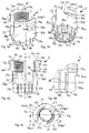
Fig. 1 shows an exploded perspective view of an embodiment of a polyaxial bone anchoring device according to the invention; -
Fig. 2 shows a perspective view of the polyaxial bone anchoring device ofFig. 1 in an assembled state; -
Fig, 3a shows a perspective view from the top of the receiving part ofFig. 1 ; -
Fig. 3b shows a perspective view from the bottom of the receiving part ofFig 1 ; -
Fig. 4a shows a cross-sectional view of the receiving part ofFigs. 3a and 3b along a line AA inFig. 4c ; -
Fig. 4b shows an enlarged view of the head receiving portion of the receiving part ofFig 4a ; -
Fig. 4c shows a top view of the receiving part ofFig 4a ; -
Fig. 4d shows a cross section of an upper art of the receiving part ofFig. 4a in an an enlarged view; -
Figs. 5a
to 5d show a cross section, a top perspective view, a top view and a bottom perspective view of a clamping ofFig. 1 ; -
Fig. 6 shows a perspective view of multiple instruments according to an embodiment of the invention each engaging a polyaxial bone anchoring device according toFig. 1 ; -
Fig. 7 shows a perspective view of the instrument according to the embodiment and the polyaxial bone anchoring device in an engaged state; -
Figs. 8a
to 8b shows a perspective view from the top and the bottom of the instrument ofFig. 7 ; -
Figs. 9a
to 9b shows a cross sectional view of the instrument ofFig. 7 in two different views perpendicular to each other. -
Fig. 10 shows an enlarged perspective view of a front end portion of the instrument ofFig. 7 ; -
Fig. 11 shows a view onto the front end portion ofFig,. 10 along a central axis of the instrument ofFig. 7 ; -
Fig. 12 shows a side view of the inner wall surface of one of the legs of the front end portion of the instrument; -
Fig. 13a
to 13d show steps of engaging the polyaxial bone anchoring device using the instrument ofFig. 7 ; -
Figs. 14a
to 14b show cross sectional views of the instrument and polyaxial bone anchoring device in an engaged state; -
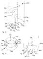
Fig. 15 shows an enlarged view engagement portions and structures of the instrument and the polyaxial bone anchoring device in an engaged state, respectively; -
Fig. 16a shows a side view of the instrument and the polyaxial bone anchoring device in an engaged state; -
Fig. 16b shows a horizontal cross sectional view taken along line BB inFig. 16a ; -
Fig. 16c shows a horizontal cross sectional view taken along line CC inFig. 16a ; -
Fig. 17a
to 17c shows alternative embodiments of engagement structures at a receiving part. - As shown in
Figs. 1 and 2 , a bone anchoring device according to an embodiment of the invention includes abone anchoring element 1 in the form of, for example, a bone screw having ashank 2 with a threaded portion and ahead 3 with a spherically-shaped outer surface portion. Thehead 3 may have arecess 4 for engagement with a driver or tool. The bone anchoring device also includes a receivingpart 5 for receiving arod 6 to be connected to thebone anchoring element 1. Further, apressure member 7 may be provided in the receivingpart 5 for exerting pressure onto thehead 3 of thebone anchoring element 1. In addition, the bone anchoring device includes aclamping ring 8 that is mountable to the receivingpart 5 for compressing a portion of the receivingpart 5 to exert pressure onto thepressure element 7 and in turn onto thehead 3. Lastly, the bone anchoring element also includes afixation element 9 in the form of, for example, an inner screw or set screw for fixing therod 6 in the receivingpart 5. Meanwhile, thefixation element 9 in the form of an inner screw has a thread corresponding to theinternal thread 53 provided on thelegs - The receiving
part 5 will be described in greater detail referring additionally toFigs. 3a to 4d . The receivingpart 5 includesfirst end 5a and an oppositesecond end 5b and a central axis C that passes through thefirst end 5a and thesecond end 5b. Thefirst end 5a may serve as an abutment for a portion of the instrument as described in greater detail below. Apassage 51 extends through the receivingpart 5 from thefirst end 5a to thesecond end 5b. Thepassage 51 may be formed as a cylindricalcoaxial bore 51a in a region from thefirst end 5a to a distance from thefirst end 5a and may in this embodiment narrow into anaccommodation space 51b with an inner diameter that decreases towards thesecond end 5b until a region with a minimum diameter is reached. Theaccommodation space 51b serves for accommodatinghead 3 of thebone anchoring device 1 and at least a portion of thepressure member 7, as can be seen also inFigs. 14a, 14b . Adjacent thesecond end 5b, a tapered or more specifically conically shapedbottom opening portion 51c extends from the region having the minimum diameter. - A substantially
U-shaped recess 52 extends from thefirst end 5a in direction of the second end 9b wherein a width of therecess 52 is slightly larger than a diameter of therod 6, such that therod 6 can be placed in therecess 52 and can be guided therein. Therecess 52 forms a channel for therod 6. By means of therecess 52, twofree legs 52ainternal thread 53 may be provided. In this embodiment, theinternal thread 53 extends from anannular end surface 10 defined byfirst end 5a up to a distance from thefirst end 5a inside thebore 51. Theinternal thread 53 can be, for example, a metric thread, a flat thread, a negative angle-thread, a saw-tooth thread or any other thread form. Preferably, a thread form such as a flat thread or a negative angle thread is used to prevent or reduce the splaying of thelegs fixation element 9 is screwed-in. An undercut 59 is formed adjacent tointernal thread 53 in a direction away from thefirst end 5a, as can be seen inFig. 4a . - An
upper part 50 of the receivingpart 5 which is adjacent to thefirst end 5a has a substantially cylindrical outer surface except for example two flat recessedportions 56a, 56b, etc., which will explained in more detail below. Also, at the outer surface of theupper part 50 of the receivingpart 5, a first engagement structure for engagement with the instrument are provided, wherein the first engagement structure may be formed by twocircumferential ribs leg ribs lower end 50a of theupper portion 50. Each of theribs upper portion 50, for example, for approximately a quarter circle or less, for example by an angle of about 60° (seeFig. 4c ) as in the embodiment shown. The arrangement is such that one end 540a1, 540b1 of eachrib recess 52 and the other end 540a2, 540b2 of each rib extends approximately to the middle section of eachleg free surface portion leg rib U-shaped recess 52. - Furthermore, the
ribs coaxial bore 51 and a longitudinal axis L of therecess 52. More specifically, the position of theribs rib 54a of theleg 52a extends to therod receiving recess 52 at one side of the receivingpart 5 and therib 54b extends to therod receiving recess 52 at the other side of the receivingpart 5. This permits the instrument to be placed first onto the rib-free portions ribs - The
ribs Figs. 4a and4d , a dovetail-shape which in this embodiment is single-sided is preferable. Namely, theribs upper surface 141 which extends substantially perpendicular to the central axis C, while abottom surface 142 is inclined and extends radially downwards, i.e., towards the distal direction. In other words, a width of theribs upper surface 141 in this embodiment is flush with theannular end surface 10 of thelegs part 5 which is provided at thefirst end 5a. Nevertheless, in an alternative embodiment illustrated inFig. 17a , ribs 54' of modified receiving part 5' may also have a full two-sided dovetail-shape. Theannular end surface 10 needs not to be planar. It may have an inclination directed inwards or outwards, or may be rounded. In preferred embodiments, the upper surface of theribs annular end surface 10. - In any case, the
ribs annular end surface 10 of thelegs first end 5a of the receivingpart 5, 5' or at least adjacent to thatannular end surface 10 atfirst end 5a. Protrusions or recesses formed in the annular end surface are not ruled out, as long as theannular end surface 10 atfirst end 5a may serve as an abutment surface for the instrument as described below. A distance of theupper surface 141 of theribs annular end surface 10 of less than a width of the ribs in a direction parallel to the central axis C may be acceptable and is covered by the term "adjacent". - An advantage of the arrangement of
ribs part 5 directly at or adjacent to anannular end surface 10 at thefirst end 5a arises from the fact that engagement features of bone anchoring device are positioned away from the bone surface when the anchoring element is implanted within the bone and the head of the anchoring element is received in the accommodation space of the receiving part. This in turn allows that the instrument engages the device remote from the bone surface which avoids damages to the body tissue and permits to create small incisions. Also, this structure of the receiving part allows the engaging instrument to be configured more stable and sustainable, which will become clear from explanations with regard to the instrument below. - It is noted that the ribs may also have a substantially rectangular, trapezoidal, rhomboid-shaped, tooth-shaped or rounded cross-section, etc., or with regard to further modified receiving
parts 5", 5"', theribs 54", 54"' may even have complex shapes as illustrated inFigs. 17b or 17c , respectively. Theribs leg ribs 54a, b, such asstop ribs 54a', 54b' as examples of third engagement structures. - Stop
ribs 54a', 54b' have a length less than that of theribs Figs. 3a, 3b . Nevertheless, similar toribs ribs 54a', 54b' extend from therod receiving recess 52 at respective sides of the receivingpart 5, and also extend in a distance and parallel toribs upper part 5. The cross section ofstop ribs 54a', 54b' is in this embodiment rectangular as can be seen inFig. 4a , but the same shapes as detailed with regard toribs ribs 54a', 54b' may also include rounded and/or inclined end portions. The width may be equal to or less than that ofribs stop ribs 54a', 54b' is smaller than that ofribs stop ribs 54a', 54b' are arranged directly at or adjacent to anupper end wall 561 of recessedsurface portions 56a, 56b. - As noted, the outer surface of the receiving
part 5 also includes the substantially flat or planar recessedportions 56a, 56b. Recessedportions 56a, 56b are positioned at theupper part 50 in a circumferential direction in correspondence with thecircumferentially extending ribs edge 50a at a bottom end ofupper art 50 in a proximal direction parallel to the central axis C up to a predetermined distance from the ribs 14a, 14b. The recessedportions 56a, 56b need not have a planar flat surface recessed from a cylindrical outer contour of the receivingpart 5 as in the embodiment but may also be rounded and/or provided with side walls. The recessedportions 56a, 56b serve as a guiding surface for upwardly projectingarms 83a, 83b of clampingring 8 as will be detailed below. - Between the
upper part 50 and thesecond end 5b of the receivingpart 5 ahead receiving portion 57 of the receivingpart 5 is provided that includes theaccommodation space 51b. Thehead receiving portion 57 also has a substantially cylindrical outer surface that has a smaller diameter than the diameter of theupper part 50 of the receivingpart 5. Adjacent thesecond end 5b, there is aportion 57a of the outer surface that slightly tapers outwards. Thehead receiving portion 57 comprises theaccommodation space 51b. To allow insertion of thehead 3, thehead receiving portion 57 is flexible. In the embodiment shown, thehead receiving portion 57 consists of a plurality of flexible wall sections 57b that are separated byslits 58 extending in longitudinal direction and being open towards thesecond end 5b. According to embodiments, theslits 58 may or may not extend even up into theupper part 50 of receivingpart 5, as can be seen inFigs. 3a and 3b . The number and size of theslits 58 is provided depending on the desired flexibility of thehead receiving portion 57. - An inner diameter of the
passage 51 at thesecond end 5b is smaller than a diameter of thehead 3 of anchoringelement 1. Due the flexibility of thehead receiving portion 57 thehead 3 could be inserted from thesecond end 5b, but with theclamping ring 8 arranged in place embracing thehead receiving portion 57, there is not sufficient expansion of the flexible wall sections 57b to allow insertion from the bottom end. In use, the anchoringelement 1 in this embodiment will rather be inserted into the receivingpart 5 viafirst end 5a (i.e., top loading). - The
clamping ring 8 will be described in greater detail referring additionally toFigs. 5a to 5d . Theclamping ring 8 comprises an upper end orfirst end 8a and an opposite lower end or second end 8b and may have a substantially sphericalouter surface 81 which narrows towards the second end 8b. The outer diameter of thespherical surface 81 at or adjacent thefirst end 8a may be such that when theclamping ring 8 is mounted around thehead receiving portion 57 of the receivingpart 5, the outerspherical surface 81 of the clamping ring and the outer cylindrical surface of theupper part 50 of a receivingpart 5 are flush with each other as depicted, for example, inFig. 2 . An inner diameter of theclamping ring 8 is such that theclamping ring 8 can be mounted around thehead receiving portion 57 wherein theupper end 8a faces towards the bottom end oredge 50a of theupper part 50 of the receivingpart 5. Alignment features in the form offlat portions 82 are provided at theouter surface 81 of theclamping ring 8. Theflat portions 82 are offset by 180°. The alignment features may assist in aligning theclamping ring 8 correctly with respect to the receivingpart 5, in particular with respect to further flat surfaces 50b recessed from the cylindrical outer surface ofupper part 50 directly below theU-shaped recess 52, seeFig. 3a . It shall be noted, however, that the shape of the outer surface of clampingring 8 may be different in other embodiments. For example, theouter surface 81 may have a cylindrical shape etc. - As can be seen in particular seen in
Fig. 5a , clampingring 8 further has a first innercylindrical surface portion 86 that is adjacent or substantially adjacent to theupper end 8a. There may be a small inclined surface or bevelled surface (not shown) provided adjacent to theupper end 8a to facilitate mounting. Adjacent or substantially adjacent to the lower end 8b, a secondinner surface portion 87 of theclamping ring 8 may be tapered in such a manner that the inner diameter conically widens towards the lower end 8b. The secondinner surface portion 87 is configured to cooperate with theouter surface portion 57a of the head receiving portion in such a manner that when theclamping ring 8 is moved towards a lowermost position on thehead receiving portion 57, the cooperatingsurfaces 57a of thehead receiving portion clamping ring 8 exert an increasing inwardly directed radial force towards thehead 3. Moreover, a height of the ring-shaped base portion (between ends 8a, 8b, i.e., withoutarms 83a, 83b) of clampingring 8 in an axial direction, as can be seen inFigs. 14a and 14b , corresponds substantially to a height of thehead receiving portion 57 of the receivingpart 5. - The
clamping ring 8 includes two upwardly projectingarms 83a, 83b extending from ashoulder 85 formed atfirst end 8a. As can be seen particularly inFigs. 2 ,14a and 14b , the length ofarms 83a, 83b substantially corresponds to a length of recessedportions 56a, 56b (as measured from theedge 50a at the bottom end of upper part 50) in a direction parallel to the central axis C, which are arranged to slideably receivearms 83a, 83b, when thelocking ring 8 is attached to the receiving part. Each ofarms 83a, 83b has end faces 89 which may abut on or at least may approach close to -upper end wall 561 of the recessedportions 56a, 56b. Similarly, the width ofarms 83a, 83b substantially corresponds to that of recessedportions 56a, 56b. The twoarms 83a, 83b are located diametrically opposite to each other and are positioned asymmetrically with respect to theflat portions 82. More specifically, the position of botharms 83a, 83b is rotated in the same direction by for example about 60° in this non-limiting embodiment with respect toflat portions 82 in the circumferential direction, which is indicated inFig. 5c by the dash-dotted axis R that will be aligned with longitudinal axis L of theU-shaped recess 52 in an assembled state. - Each of two upwardly projecting
arms 83a, 83b includes an engagement structure for engagement with an instrument on its outer surface within or adjacent a tip portion of the respective arm which in this embodiment is provided as a dovetail-shaped circumferentially extending engagement structure formed as anotch 88a, 88b. As already noted above a consequence of such positioning at a tip portion of thearms 83a, 83b, the engagement structure of thelocking ring 8 as well as the engagement structure of the receiving part are located (i) close to each other and (ii) at a portion of a respective piece most proximate to thefirst end 5a of the receivingpart 5 and away from the head receiving portion 18, i.e., away from the bone surface when the polyaxial bone anchoring device is in an assembled state in-situ. This allows to require less space within the body tissue by an instrument for performing steps of intermittent locking/unlocking during, e.g., repositioning of single vertebra or readjusting of a receiving part with an unlocked rod, wherein theclamping ring 8 is engaged and axially displaced by for example an outer tube of a locking/unlocking instrument with respect to an inner tube of the locking/unlocking instrument, which engages the receivingpart 5. - According to embodiments of the invention, the
arms 83a, 83b have a sufficient length that the engagement structures provided on the arms, such asnotches 88a, 88b, are arranged at an axial position in the direction of the central axis C corresponding to that of therod 6 when the rod is received in theU-shaped recess 52 and pressed against the pressure member 7 (i.e., in a locked state of the bone anchoring device), preferably even at or above an axial position of a largest diameter of therod 6 like in the embodiment illustrated herein, seeFigs. 14a, 14b . - In compliance with the dovetail-shaped cross sectional profile, a width of
notches 88a, 88b decreases in a direction radially outwards towards the outer surface of arms 83b. Thenotches 88a, 88b include acylindrical base surface 880 coaxial with the central axis C and correspondingly inclined bottom surfaces 881 andupper surfaces 882 as can be seen in more detail inFig. 4a . It is noted that the engagement structure provided at thearms 83a, 83b need not be anotch 88a, 88b but may also be provided as a protruding rib as in the case ofribs notches 88a, 88b or ribs may be substantially rectangular, trapezoidal, rhomboid-shaped, tooth-shaped or rounded, etc. instead of being dovetail-shaped. - A length of the engagement structures, e.g.,
notches 88a, 88b, is limited to the width of thearms 83a, 83b and substantially corresponds to that of the engagement structures of the receiving part, i.e., thecircumferential ribs portions 56a, 56b and a thickness of the arms measured in radial direction is defined such that thecylindrical base surface 880 ofnotches 88a, 88b is substantially flush with the cylindrical outer surface of the receivingpart 5, when the locking ring is assembled with the receiving part. As a consequence, a dovetail-shaped circumferentially extending rib as an example of an engagement portion in an outer tube of the locking/unlocking instrument may be smoothly slid into acorresponding notch 88a, 88b of thelocking ring 8. However, a small step between the cylindrical outer surface of the receivingpart 5 andbase surface 880 of thenotches 88a, 88b is not ruled out. Furthermore, it is not ruled out that further notches or ribs are provided atarms 83a, 83b. - The
pressure member 7 as shown inFigs. 1 and14a, 14b comprises a substantially cylindricalouter surface 71 which has a diameter that is equal to or slightly smaller than an inner diameter of the cylindricalcoaxial bore 51a to facilitate sliding an accommodation therein.Pressure member 7 also has arod receiving portion 72 which is cylinder-segment shaped for receiving arod 6 therein and which forms two legs opposite each other, which face the first end of the receiving part when thepressure member 7 is inserted in thecoaxial bore 51a. Moreover, a sphericalhollow section 73 is formed at a lower end ofpressure member 7 which contacts thehead 3 of anchoringelement 1 and may exert pressure transferred from an insertedrod 6 onto thehead 3 to lock the same when forexample fixation element 9 is tightened. The pressure member may further comprise a coaxial hole allowing access torecess 4 which provided in thehead 3 of anchoringelement 1. - The receiving
part 5, theclamping ring 8, thepressure member 7, thefixation element 9 and thebone anchoring element 1 may be made of bio-compatible materials, for example of titanium or stainless steel, of a bio-compatible alloy, such as a NiTi-alloys, for example Nitinol, magnesium or magnesium alloys or from a bio-compatible plastic material, such as, for example, polyether ether ketone (PEEK) or poly-1-lactide acid (PLLA). The parts can be made of the same or of different materials. - In operation, the polyaxial
bone anchoring device 100 is first assembled by attaching theclamping ring 8 to the flexiblehead receiving portion 57 via thesecond end 5b, wherein the flexible wall sections 57b are slightly compressed by the first and secondinner surface portions clamping ring 8. Also, thebone anchoring element 1 is inserted into the receivingpart 5 via thefirst end 5a. Thepressure member 7 may then also be slid into thecoaxial bore 51a of receivingpart 5, and theanchoring element 1 is applied to a bone using, e.g" a driver or tool. Arod 6 may then be guided into theU-shaped recess 52 of receivingpart 5 and using a locking/unlocking instrument the clamping ring is axially moved into the distal direction away from thefirst end 5a towards a lowermost position on thehead receiving portion 57 to clamp thehead 3, wherein the conical secondinner surface portion 87 of clampingring 8 cooperates with theouter surface portion 57a of the head receiving portion in such a manner that an increasing inwardly directed radial force is exerted towards and onto thehead 3. - Thereby, the
fixation element 9 needs not to be tightened yet. Rather, a locking/unlocking instrument allows a temporary clamping and/or unclamping via the actuating, i.e., moving clamping ring between a clamping position and a pre-locking position. This function permits the operator to readjust and fix an angular position of the receiving part with respect to the anchoring element even without an inserted rod, or to reposition individual vertebrae via the attached instrument. Nevertheless, final fixation will be effected by tightening thefixation element 9 and thus pressing thepressure member 7 against thehead 3 to lock the same. - Next, an
instrument 200 for use with the polyaxialbone anchoring device 100 will be explained with reference toFigs. 6-12 . Theinstrument 200 functions as a head extension device which is configured to be attached to the receivingpart 5 in-situ and thereby allows manipulating the receivingpart 5 or supplying further instruments and/or parts to the receivingpart 5. Multiplesuch instruments 200 may be attached to respective polyaxialbone anchoring devices 100 in-situ as illustrated inFig. 6 , the polyaxialbone anchoring devices 100 being positioned within vertebrae, respectively. Unlike the above explained instrument for locking/unlocking theclamping ring 8, which also engages theclamping ring 8 in addition to the receivingpart 5, theinstrument 200 is arranged to only engage theribs part 5 of polyaxialbone anchoring device 100 disclosed herein are encompassed by the appended claims. - The
instrument 200 includes atubular member 202 having afront end portion 204, which comprises engagement portions for engagement with the engagement structures of the receiving part, and arear end portion 206 as can be seen inFig. 7 . - As shown in
Figs. 8a-9b , thetubular member 212 includes aninner bore 212 extending from therear end portion 206 to thefront end portion 204, and the front end portion 24 is provided with a substantially rectangular-shapedrecess 214 into which thebore 212 opens, and which forms twofree legs 214a, 214b. Theinner bore 212 has a diameter smaller than that of the receivingpart 5.Inner bore 212 ends at anannular abutment surface 217, which serves to abut onannular end surface 10 of receivingpart 5 during engagement. Thetubular member 212 further has recessedportions 210 at opposite sides thereof in a region of therear end portion 204, which may serve for attaching further instruments or for gripping the instrument. - As can be seen in
Fig. 10 , thelegs 214a, 214b each include arounded tip portion 215a, 215b, respectively, which facilitates insertion of the instrument into the incision or hole in the tissue and guiding to the in-situ position of the receivingpart 5. A length of the roundedtip portion 215a, 215b in a direction of a central axis T of the instrument is small compared to the a portion of the free legs which has a substantially cylindrical contour and constant width measured in a radial direction from thecentral bore 212. - At an inner surface of the instrument in a region of the
tip portion 215a, 215b of the free legs of thefrond end portion 214 there are provided twoengagement portions 216a, 216b in the form ofnotches 216a, 216b. Thesenotches 216a, 216b have a single-sided dove-tail-shaped cross section, which is complementary to that of theribs part 5.Notches 216a, 216b are configured to slideably receive theribs Notches 216a, 216b extend between the recess walls and open into therecess 214 on both sides thereof in the circumferential direction around central axis T and have a length which corresponds to that ofribs ribs legs 214a, 214b. - Moreover, second engagement portions in the form of
stop notches 218a, 218b are provided directly at the edge of thetip portions 215a, 215b extending from the recess at oneopen end 220a thereof in a circumferential direction around central axis T. More specifically, thenotches 218a, 218b have a length shorter than that ofnotches 216a, 216b. As a consequence, stopnotches 218a, 218b include an end or abutment face 220b facing in a circumferential direction, in this embodiment facing in the counter-clockwise direction in both cases. - Stop
notches 218a, 218b are configured to slideably receivestop ribs 54a', 54b' therein during engagement by rotation in a circumferential direction as will be detailed below. However, as a consequence of the abutment faces 220b, rotational movement of theinstrument 200 with respect to the receivingpart 5 is limited by these abutment faces 220b functioning as a stop. Advantageously, such stop guarantees that theinstrument 200 attains a correctly aligned engagement position with respect to the receivingpart 5 and does not unintentionally lose contact with the receiving part during use, which otherwise might be harmful for the patient and also might damage the engagement features. - Still further, as can be seen in
Fig. 10 , thestop notches 218a, 218b do no need to have a lower wall. Rather, thenotches 218a, 218b are also open towards the distal direction, i.e., towardssecond end 5b of receivingpart 5. Since an axial position of theinstrument 200 with respect to the receivingpart 5 is already defined byribs notches 216a, 216b, the lower walls can be omitted and thestop notches 218a, 218b herein merely provide for the stop function. Due to the omission of the lower walls, the tip edge ofinstrument 200 is further closer to theribs - As can be seen in
Fig. 12 , the stop notches nevertheless have an upper guiding wall, which, however, has two sections, namely an annularhorizontal section 221 which extends in a plane perpendicular to the central axis T, and aninclined section 222. Thehorizontal section 221 is located extending from theopen end 220a ofnotches 218a, 218b, while theinclined section 222 extends adjacent tohorizontal section 221 up to the abutment face 220b at the other end ofnotches 218a, 218b. The inclination is such that the width ofnotches 218a, 218b narrows towards the abutment end 220b. As a consequence, during sliding-in of arib 54a', 54b' received in one of thenotches 218a, 218b from theopen end 220a in a rotational movement towards the abutment face 220b,such rib 54a', 54b' eventually contacts the inclined surface which in turn creates a frictional force between therib 54a', 54b' and the inclined surface 220b. - Advantageously, this function on the one hand assists in maintaining an engaged state of the
instrument 200 with the receivingpart 5 and prevents unintentional loosening. On the other end, the operator obtains a tactile response during the rotational movement of the instrument that he is approaching the stop. - It is noted that between the
notches notches inner surface 219, which as compared with the inner surface ofinner bore 212 has an enlarged diameter, which corresponds to the diameter of the outer cylindrical surface of theupper part 50 of the receivingpart 5. This cylindricalinner surface 219 serves for guiding the instrument while placing the instrument on the receivingpart 5 as will be explained in the following. - A use of the
instrument 200 and the polyaxialbone anchoring device 100 is shown inFigs. 13a-d . As shown inFig. 13a theinstrument 200 is moved to the receivingpart 5 in a direction of the central axes C, T being aligned with each other. Thereby, thefree legs 214a, 214b are aligned with the rib-free portions part 5, respectively, in a circumferential direction. - In
Fig. 13b , theinstrument 200 is guided over the receivingpart 5. The cylindricalinner surface 219 of theinstrument 200 slideably contacts the outer cylindrical surface of the upper part of the receivingpart 5 and crosses the rib-free portions - In
Fig. 13c , the downward movement of theinstrument 200 stops wherein theannular abutment surface 217 at the end ofbore 212 abuts on theannular end surface 10 of the receiving part. The roundedtip portion 215a, 215b having the engagement portions arranged at its inner wall is in this situation located at an axial position of theengagement structures - In
Fig. 13d , theinstrument 200 is rotated in the circumferential direction as indicated by the arrow. Thereby, theribs part 5 slide with leading end portions 540a2, 540b2 into therespective notches 216a, 216b of theinstrument 200, and theribs 54a', 54b' slide with leading end portions 540a2', 540b2' into therespective notches 218a, 218b of theinstrument 200. Initially, theinclined surface 222 has contacted an upper surface ofribs 54a', 54b' creating an increasing friction and slight tension between theribs ribs 54a', 54b' abut on respective abutment faces 220b. The increasing friction thereby leads to self-locking of the engagement between the receivingpart 5 and the instrument, whereby the abutment serves to define an aligned endpoint of the rotational movement. - In this final engagement position, which is also shown in
Figs. 14a and 14b , the operator may perform desired steps of assembling and orienting the polyaxial bone anchoring device.Fig. 15 shows an enlarged detail of the engagement structures and portions.Figs. 16b and 16c reveal horizontal cross sections in the engaged position. - Various modifications may be made without departing from the scope defined by the appended claims. For example, as noted above, the instrument may be different from the head extension instrument and may for example be locking/unlocking instrument.
- Moreover, the polyaxial bone anchoring device may include a pressure member formed as an inner cap itself having a flexible head receiving portion as described for example in
European patent application no 16 128 818.1 Fig. 3 are replaced with an arrangement of ribs as explained above while all other features are maintained. - However, it may also be conceived to add
arms 83a, 83b as described above to the clamping ring disclosed inEuropean patent application 16 128 818.1
Claims (15)
- A bone anchoring device (100), comprising:a receiving part (5) for coupling a rod (6) to a bone anchoring element (1), the receiving part (5) comprising a first end (5a), a second end (5b), and a central axis (C) extending between the first end (5a) and the second end (5b), and an end surface (10) provided at the first end (5a), a recess (52) at the first end (52) for receiving a rod (6), and a head receiving portion (57) at the second end (5b) for pivotably holding a head (3) of a bone anchoring element (1), the head receiving portion (57) being at least partially flexible;a clamping ring (8) configured to be arranged around the head receiving portion (57), wherein when the clamping ring (8) is around the head receiving portion, the clamping ring (8) can assume a locking position wherein the clamping ring (8) exerts a force onto the head receiving portion (57) such that an inserted head (3) is locked and a non-locking position wherein an inserted head (3) is pivotable relative to the receiving part (5,5');wherein the receiving part (5) further comprises at least one first engagement structure (54a, 54b) configured to be engaged by an engagement portion of an instrument, wherein the engagement structure (54a, 54b) is positioned directly at or adjacent to the end surface (10) at the first end (5a).
- The bone anchoring device (100) of claim 1, wherein at least one second engagement structure (88a, 88b) is provided, which is configured to be engaged by a further engagement portion of the instrument and which is arranged at the clamping ring (8), to allow axial displacement of the clamping ring (8) relative to the receiving part (5).
- The bone anchoring device (100) of claim 1 or 2, wherein the clamping ring (8) comprises an upwardly projecting arm (83, 83b), wherein the second engagement structure (88a, 88b) is provided at the upwardly projecting arm (83, 83b).
- The bone anchoring device (100) of claim 3, wherein second engagement portion (83a, 83b) is arranged in a region of the tip of the upwardly projecting arm (83a, 83b), and
wherein the upwardly projecting arm (83a, 83b) has a length such that the second engagement portion (83a, 83b) is arranged at a position in a direction along the central axis which corresponds to a position of an inserted rod (6) locked in the receiving part (5) by a fixation element (9), or to an axial position between the rod (6) and the first end (5a). - The bone anchoring device (100) of claim 4, wherein the first engagement structure (54a, 54b) and/or the second engagement structure (88a, 88b) are formed to be engaged by a rotational movement of the instrument or a portion of the instrument in a circumferential direction around the central axis, or are preferably formed as a circumferential rib.
- The bone anchoring device (100) of claim 4 or 5, wherein the receiving part (5) further comprises a recessed portion (56a, 56b) extending from an edge (50a) facing the head receiving portion (57) in a direction of the central axis (C) up to a distance from the first end (5a) of the receiving part (5).
- The bone anchoring device of one of claims 1 to 6, wherein the first engagement structure (54a, 54b) and/or the second engagement structure (88a, 88b):- have a dovetail-shaped cross section, or a cross section like a dovetail only on a single side; and/or- are arranged at an outer circumferential surface of the receiving part (5) and the clamping ring (8) and extend farther radially outward than all other parts of the receiving part (5) or the clamping ring (8), respectively.
- The bone anchoring device of one of claims 1 to 7, wherein an upper surface of the engagement structure (54a, 54b) is oriented away from the second end (5b) is flush with the end surface (10) at the first end (5a).
- The bone anchoring device of one of claims 1 to 8, wherein the end surface is provided as an annular-segment shaped end surface of legs (52a, 52b), which are formed by the U-shaped recess (52).
- The bone anchoring device of one of claims 1 to 9, further comprising a pressure member (7) configured to extend to exert pressure onto an inserted head (3).
- The bone anchoring device of one of claims 2 to 10, wherein the first engagement structure (54a, 54b) and the second engagement structure (88a, 88b) each are arranged asymmetric with respect to a plane extending through the central axis (C) of the receiving part and through a longitudinal axis (L) of the recess (52) for receiving the rod (6).
- The bone anchoring device of one of claims 1 to 11, wherein at least one third engagement structure (54a', 54b') is provided at the receiving part (5), which is aligned with the first engagement structure (54a, 54b) in the circumferential direction and arranged in a distance away from the first engagement portion in a direction along the central axis (C), wherein the third engagement structure (54a', 54b') comprises an abutment end (540a2', 540b2') facing in a circumferential direction.
- A system of an instrument (200) and a bone anchoring device (100) according to claim 12, the instrument comprising
at least one tubular member (202) comprising:at least one first engagement portion (216a, 216b) formed as a notch and positioned for engaging the first engagement structure (54a, 54b) at the receiving part (5); andat least one second engagement portion (218a, 218b) positioned for engaging the third engagement structure (54a', 54b') at the receiving part (5), wherein the second engagement portion has an abutment face (220b) facing and abutting against the abutment end (540a2', 540b2') of the third engagement structure (54a', 54b'), when the first engagement structure and the second engagement portion engage with each other. - The system according to claim 13, wherein the second engagement portion (218a, 218b) comprises a self-locking mechanism, which is provided by a guiding wall of the second engagement portion which has an inclined section with respect to a circumferential direction.
- A system of an instrument (200) and a bone anchoring device (100) according to one of claims 1 to 12, the instrument comprising
at least one tubular member (202) comprising:at least one first engagement portion (216a, 216b) formed as a notch and positioned for engaging the first engagement structure (54a, 54b) at the receiving part (5)
Priority Applications (7)
| Application Number | Priority Date | Filing Date | Title |
|---|---|---|---|
| EP16185554.9A EP3287089B1 (en) | 2016-08-24 | 2016-08-24 | Polyaxial bone anchoring device and system of an instrument and a polyaxial bone anchoring device |
| US15/669,541 US10492833B2 (en) | 2016-08-24 | 2017-08-04 | Polyaxial bone anchoring device and system of an instrument and a polyaxial bone anchoring device |
| CN201710722344.7A CN107773296B (en) | 2016-08-24 | 2017-08-22 | Polyaxial bone anchoring device and instrument and system of polyaxial bone anchoring device |
| JP2017160564A JP7029904B2 (en) | 2016-08-24 | 2017-08-23 | Multiaxial bone anchoring device, as well as instruments and multiaxial bone anchoring device systems |
| US16/665,510 US11344334B2 (en) | 2016-08-24 | 2019-10-28 | Polyaxial bone anchoring device and system of an instrument and a polyaxial bone anchoring device |
| US17/736,663 US12114896B2 (en) | 2016-08-24 | 2022-05-04 | Polyaxial bone anchoring device and system of an instrument and a polyaxial bone anchoring device |
| US18/890,341 US20250082368A1 (en) | 2016-08-24 | 2024-09-19 | Polyaxial bone anchoring device and system of an instrument and a polyaxial bone anchoring device |
Applications Claiming Priority (1)
| Application Number | Priority Date | Filing Date | Title |
|---|---|---|---|
| EP16185554.9A EP3287089B1 (en) | 2016-08-24 | 2016-08-24 | Polyaxial bone anchoring device and system of an instrument and a polyaxial bone anchoring device |
Publications (2)
| Publication Number | Publication Date |
|---|---|
| EP3287089A1 true EP3287089A1 (en) | 2018-02-28 |
| EP3287089B1 EP3287089B1 (en) | 2019-07-24 |
Family
ID=56799365
Family Applications (1)
| Application Number | Title | Priority Date | Filing Date |
|---|---|---|---|
| EP16185554.9A Active EP3287089B1 (en) | 2016-08-24 | 2016-08-24 | Polyaxial bone anchoring device and system of an instrument and a polyaxial bone anchoring device |
Country Status (4)
| Country | Link |
|---|---|
| US (4) | US10492833B2 (en) |
| EP (1) | EP3287089B1 (en) |
| JP (1) | JP7029904B2 (en) |
| CN (1) | CN107773296B (en) |
Cited By (1)
| Publication number | Priority date | Publication date | Assignee | Title |
|---|---|---|---|---|
| EP4074271A1 (en) * | 2021-04-15 | 2022-10-19 | Biedermann Technologies GmbH & Co. KG | Polyaxial bone anchoring device |
Families Citing this family (15)
| Publication number | Priority date | Publication date | Assignee | Title |
|---|---|---|---|---|
| FR3035318B1 (en) * | 2015-04-24 | 2017-05-19 | Medicrea Int | MATERIAL OF VERTEBRAL OSTEOSYNTHESIS |
| EP3490471B1 (en) | 2016-07-29 | 2023-10-25 | Zimmer Biomet Spine, Inc. | Bone anchor housing limiter |
| EP3287089B1 (en) * | 2016-08-24 | 2019-07-24 | Biedermann Technologies GmbH & Co. KG | Polyaxial bone anchoring device and system of an instrument and a polyaxial bone anchoring device |
| EP3476340B1 (en) * | 2017-10-25 | 2021-06-02 | Biedermann Technologies GmbH & Co. KG | Polyaxial bone anchoring device |
| EP3708097B1 (en) | 2017-12-22 | 2023-06-14 | Biedermann Technologies GmbH & Co. KG | Polyaxial bone anchoring device and system of an instrument and a polyaxial bone anchoring device |
| EP3536271B1 (en) | 2018-03-06 | 2022-05-04 | Biedermann Technologies GmbH & Co. KG | Polyaxial bone anchoring device and system of an instrument and a polyaxial bone anchoring device |
| US11076842B2 (en) | 2018-08-31 | 2021-08-03 | Pro-Dex, Inc. | Surgical tool attachment devices, systems, and methods |
| US11234738B2 (en) | 2018-11-16 | 2022-02-01 | Roger P. Jackson | Pivotal bone anchor assembly having a deployable collet insert with internal pressure ring |
| US11571244B2 (en) * | 2019-05-22 | 2023-02-07 | Nuvasive, Inc. | Posterior spinal fixation screws |
| EP3838196B1 (en) * | 2019-12-18 | 2024-01-31 | Biedermann Technologies GmbH & Co. KG | Coupling device and instrument for placing a coupling device to a head of a bone anchor |
| DE102020003247A1 (en) | 2020-05-29 | 2021-12-02 | Mimeo Medical Gmbh | Modular osteosynthesis device for vertebrae |
| DE102020005928A1 (en) | 2020-09-28 | 2022-03-31 | Mimeo Medical Gmbh | Modular and temporarily fixable vertebral osteosynthesis device |
| EP4129220B1 (en) * | 2021-08-04 | 2024-07-03 | Biedermann Technologies GmbH & Co. KG | Coupling device for coupling a rod to a bone anchoring element and method of manufacturing the same |
| WO2023041951A1 (en) * | 2021-09-14 | 2023-03-23 | Agmspine, Sia | A polyaxial spinal screw |
| EP4751667A1 (en) * | 2024-12-02 | 2026-06-03 | Biedermann Technologies GmbH & Co. KG | Instrument for use with a bone anchoring device |
Citations (7)
| Publication number | Priority date | Publication date | Assignee | Title |
|---|---|---|---|---|
| US20080015576A1 (en) * | 2006-04-28 | 2008-01-17 | Whipple Dale E | Large diameter bone anchor assembly |
| US20090149887A1 (en) * | 2005-09-23 | 2009-06-11 | Fridolin Schlaepfer | Bone support apparatus |
| US20110060374A1 (en) | 2003-12-16 | 2011-03-10 | Christopher Sicvol | Percutaneous Access Devices And Bone Anchor Assemblies |
| US20120179209A1 (en) * | 2010-12-10 | 2012-07-12 | Lutz Biedermann | Receiving part for receiving a rod for coupling the rod to a bone anchoring element and a bone anchoring device |
| US20130085536A1 (en) | 2011-09-30 | 2013-04-04 | Biedermann Technologies Gmbh & Co. Kg | Bone anchoring device and tool cooperating with such a bone anchoring device |
| US20150182265A1 (en) * | 2013-12-09 | 2015-07-02 | Timo Biedermann | Extension device for a bone anchor, in particular for minimally invasive surgery |
| US20160220281A1 (en) * | 2012-07-27 | 2016-08-04 | Biedermann Technologies Gmbh & Co. Kg | Polyaxial bone anchoring device with enlarged pivot angle |
Family Cites Families (66)
| Publication number | Priority date | Publication date | Assignee | Title |
|---|---|---|---|---|
| GB9014817D0 (en) | 1990-07-04 | 1990-08-22 | Mehdian Seyed M H | Improvements in or relating to apparatus for use in the treatment of spinal disorders |
| DE4307633C1 (en) | 1993-03-11 | 1994-05-19 | Pennig Dietmar | Screw for locking marrow-cavity pin in position - has threaded section of shank near head and opposite thread on head with unthreaded section of shank between |
| DE19509332C1 (en) | 1995-03-15 | 1996-08-14 | Harms Juergen | Anchoring element |
| US5549608A (en) * | 1995-07-13 | 1996-08-27 | Fastenetix, L.L.C. | Advanced polyaxial locking screw and coupling element device for use with rod fixation apparatus |
| US5586984A (en) | 1995-07-13 | 1996-12-24 | Fastenetix, L.L.C. | Polyaxial locking screw and coupling element assembly for use with rod fixation apparatus |
| US5575792A (en) | 1995-07-14 | 1996-11-19 | Fastenetix, L.L.C. | Extending hook and polyaxial coupling element device for use with top loading rod fixation devices |
| US5728098A (en) * | 1996-11-07 | 1998-03-17 | Sdgi Holdings, Inc. | Multi-angle bone screw assembly using shape-memory technology |
| EP1117336B1 (en) | 1998-09-29 | 2004-05-19 | SYNTHES AG Chur | Device for joining a longitudinal support and bone fixation means |
| DE29819914U1 (en) | 1998-11-07 | 1999-01-07 | Aesculap AG & Co. KG, 78532 Tuttlingen | Endoscopic insertion instruments |
| US6273888B1 (en) | 1999-05-28 | 2001-08-14 | Sdgi Holdings, Inc. | Device and method for selectively preventing the locking of a shape-memory alloy coupling system |
| US6254602B1 (en) * | 1999-05-28 | 2001-07-03 | Sdgi Holdings, Inc. | Advanced coupling device using shape-memory technology |
| US6743231B1 (en) | 2000-10-02 | 2004-06-01 | Sulzer Spine-Tech Inc. | Temporary spinal fixation apparatuses and methods |
| US7862587B2 (en) * | 2004-02-27 | 2011-01-04 | Jackson Roger P | Dynamic stabilization assemblies, tool set and method |
| US7335201B2 (en) | 2003-09-26 | 2008-02-26 | Zimmer Spine, Inc. | Polyaxial bone screw with torqueless fastening |
| US7156849B2 (en) | 2003-06-16 | 2007-01-02 | Depuy Spine, Inc. | Rod reduction nut and driver tool |
| US20050080415A1 (en) * | 2003-10-14 | 2005-04-14 | Keyer Thomas R. | Polyaxial bone anchor and method of spinal fixation |
| US7967826B2 (en) | 2003-10-21 | 2011-06-28 | Theken Spine, Llc | Connector transfer tool for internal structure stabilization systems |
| US7905907B2 (en) | 2003-10-21 | 2011-03-15 | Theken Spine, Llc | Internal structure stabilization system for spanning three or more structures |
| US7090674B2 (en) | 2003-11-03 | 2006-08-15 | Spinal, Llc | Bone fixation system with low profile fastener |
| US7503924B2 (en) | 2004-04-08 | 2009-03-17 | Globus Medical, Inc. | Polyaxial screw |
| US7666189B2 (en) | 2004-09-29 | 2010-02-23 | Synthes Usa, Llc | Less invasive surgical system and methods |
| WO2006057837A1 (en) * | 2004-11-23 | 2006-06-01 | Jackson Roger P | Spinal fixation tool attachment structure |
| US7491208B2 (en) | 2005-04-28 | 2009-02-17 | Warsaw Orthopedic, Inc. | Instrument and method for guiding surgical implants and instruments during surgery |
| EP1743584B1 (en) | 2005-07-12 | 2007-09-12 | BIEDERMANN MOTECH GmbH | Bone anchoring device |
| US7988694B2 (en) | 2005-09-29 | 2011-08-02 | K2M, Inc. | Spinal fixation system having locking and unlocking devices for use with a multi-planar, taper lock screw |
| US8029546B2 (en) | 2005-12-15 | 2011-10-04 | Warsaw Orthopedic, Inc. | Variable angle offset spinal connector assembly |
| ZA200808411B (en) | 2006-04-11 | 2009-12-30 | Synthes Gmbh | Minimally invasive fixation system |
| US8821506B2 (en) | 2006-05-11 | 2014-09-02 | Michael David Mitchell | Bone screw |
| EP1900334B2 (en) * | 2006-09-15 | 2013-01-16 | BIEDERMANN MOTECH GmbH | Bone anchoring device |
| US8167910B2 (en) | 2006-10-16 | 2012-05-01 | Innovative Delta Technology Llc | Bone screw and associated assembly and methods of use thereof |
| US7699876B2 (en) * | 2006-11-08 | 2010-04-20 | Ebi, Llc | Multi-axial bone fixation apparatus |
| US7947065B2 (en) | 2008-11-14 | 2011-05-24 | Ortho Innovations, Llc | Locking polyaxial ball and socket fastener |
| CA2692772A1 (en) | 2007-07-20 | 2009-01-29 | Synthes Usa, Llc | Polyaxial bone fixation element |
| DE602007007758D1 (en) * | 2007-07-31 | 2010-08-26 | Biedermann Motech Gmbh | Bone anchoring device |
| US8888819B2 (en) | 2007-08-31 | 2014-11-18 | DePuy Synthes Products, LLC | Connector for securing an offset spinal fixation element |
| US20090069852A1 (en) | 2007-09-06 | 2009-03-12 | Warsaw Orthopedic, Inc. | Multi-Axial Bone Anchor Assembly |
| US20090105756A1 (en) | 2007-10-23 | 2009-04-23 | Marc Richelsoph | Spinal implant |
| US8128635B2 (en) | 2007-10-23 | 2012-03-06 | Zimmer Spine S.A.S. | Bone fixation tensioning tool and method |
| JP2012529969A (en) | 2008-08-01 | 2012-11-29 | ロジャー・ピー・ジャクソン | Longitudinal connecting member with tensioning cord with sleeve |
| US8506601B2 (en) | 2008-10-14 | 2013-08-13 | Pioneer Surgical Technology, Inc. | Low profile dual locking fixation system and offset anchor member |
| US8075603B2 (en) | 2008-11-14 | 2011-12-13 | Ortho Innovations, Llc | Locking polyaxial ball and socket fastener |
| ES2403194T3 (en) * | 2008-11-28 | 2013-05-16 | Biedermann Technologies Gmbh & Co. Kg | Receiving component to receive a rod for coupling with a bone anchoring element and a bone anchoring system with this receiving component |
| ES2375879T3 (en) | 2008-12-23 | 2012-03-07 | Biedermann Motech Gmbh | RECEPTION AREA OF A ROD FOR COUPLING THE ROD IN AN BONE ANCHORAGE ELEMENT AND BONE ANCHORAGE DEVICE WITH SUCH RECEPTION AREA. |
| ES2378588T3 (en) | 2008-12-30 | 2012-04-16 | Biedermann Motech Gmbh | Receiving part for receiving a rod for coupling the rod in a bone anchoring element and bone anchoring device with such receiving part |
| US9005260B2 (en) | 2009-01-15 | 2015-04-14 | Aesculap Implant Systems, Llc | Receiver body for spinal fixation system |
| US8636778B2 (en) | 2009-02-11 | 2014-01-28 | Pioneer Surgical Technology, Inc. | Wide angulation coupling members for bone fixation system |
| EP2485667A1 (en) | 2009-10-05 | 2012-08-15 | CoLigne AG | Spinal fixation system and screwdriver tool for use with the same |
| US8298275B2 (en) | 2009-10-30 | 2012-10-30 | Warsaw Orthopedic, Inc. | Direct control spinal implant |
| US8623061B2 (en) | 2009-11-23 | 2014-01-07 | Rolix Holdings, Llc | CAM lock pedicle screw |
| WO2011077511A1 (en) | 2009-12-22 | 2011-06-30 | 株式会社ロバート・リード商会 | Spine fixing device, embedding device, embedding member fixing device, and spine fixing system |
| ES2394774T3 (en) | 2010-05-05 | 2013-02-05 | Biedermann Technologies Gmbh & Co. Kg | Receiver piece intended to receive a bar for coupling with an anchoring element for bone, anchoring device for bone and method and tool for mounting it |
| US8882817B2 (en) | 2010-08-20 | 2014-11-11 | K2M, Inc. | Spinal fixation system |
| US8974501B2 (en) | 2010-10-18 | 2015-03-10 | Alphatec Spine, Inc. | Distal loading receiver for a polyaxial bone screw and method for implantation thereof |
| EP2462888B1 (en) * | 2010-12-10 | 2015-02-18 | Biedermann Technologies GmbH & Co. KG | Receiving part for receiving a rod for coupling the rod to a bone anchoring element and bone anchoring device with such a receiving part |
| US9186184B2 (en) | 2011-02-14 | 2015-11-17 | Pioneer Surgical Technology, Inc. | Spinal fixation system and method |
| EP2918237A1 (en) * | 2011-09-15 | 2015-09-16 | Biedermann Technologies GmbH & Co. KG | Polyaxial bone anchoring device with enlarged pivot angle |
| DE102011054203A1 (en) | 2011-10-05 | 2013-04-11 | Aesculap Ag | Readjustable polyaxial pedicle screw |
| EP2591739A1 (en) | 2011-11-14 | 2013-05-15 | Biedermann Technologies GmbH & Co. KG | Polyaxial bone anchoring device |
| EP2591738A1 (en) | 2011-11-14 | 2013-05-15 | Biedermann Technologies GmbH & Co. KG | Polyaxial bone anchoring device |
| ES2552987T3 (en) * | 2012-07-03 | 2015-12-03 | Biedermann Technologies Gmbh & Co. Kg | Polyaxial bone anchoring device |
| US10058354B2 (en) | 2013-01-28 | 2018-08-28 | Roger P. Jackson | Pivotal bone anchor assembly with frictional shank head seating surfaces |
| US9566092B2 (en) | 2013-10-29 | 2017-02-14 | Roger P. Jackson | Cervical bone anchor with collet retainer and outer locking sleeve |
| US20150134006A1 (en) | 2013-11-08 | 2015-05-14 | Blackstone Medical, Inc. | Lockable Pedicle Fastener |
| US9895171B2 (en) | 2014-07-29 | 2018-02-20 | Transcendental Spine, Llc | Modular polyaxial bone screw |
| EP3318207B1 (en) | 2015-07-24 | 2021-11-24 | Biedermann Technologies GmbH & Co. KG | Polyaxial bone anchoring device and instrument for use with the same |
| EP3287089B1 (en) * | 2016-08-24 | 2019-07-24 | Biedermann Technologies GmbH & Co. KG | Polyaxial bone anchoring device and system of an instrument and a polyaxial bone anchoring device |
-
2016
- 2016-08-24 EP EP16185554.9A patent/EP3287089B1/en active Active
-
2017
- 2017-08-04 US US15/669,541 patent/US10492833B2/en active Active
- 2017-08-22 CN CN201710722344.7A patent/CN107773296B/en active Active
- 2017-08-23 JP JP2017160564A patent/JP7029904B2/en active Active
-
2019
- 2019-10-28 US US16/665,510 patent/US11344334B2/en active Active
-
2022
- 2022-05-04 US US17/736,663 patent/US12114896B2/en active Active
-
2024
- 2024-09-19 US US18/890,341 patent/US20250082368A1/en active Pending
Patent Citations (7)
| Publication number | Priority date | Publication date | Assignee | Title |
|---|---|---|---|---|
| US20110060374A1 (en) | 2003-12-16 | 2011-03-10 | Christopher Sicvol | Percutaneous Access Devices And Bone Anchor Assemblies |
| US20090149887A1 (en) * | 2005-09-23 | 2009-06-11 | Fridolin Schlaepfer | Bone support apparatus |
| US20080015576A1 (en) * | 2006-04-28 | 2008-01-17 | Whipple Dale E | Large diameter bone anchor assembly |
| US20120179209A1 (en) * | 2010-12-10 | 2012-07-12 | Lutz Biedermann | Receiving part for receiving a rod for coupling the rod to a bone anchoring element and a bone anchoring device |
| US20130085536A1 (en) | 2011-09-30 | 2013-04-04 | Biedermann Technologies Gmbh & Co. Kg | Bone anchoring device and tool cooperating with such a bone anchoring device |
| US20160220281A1 (en) * | 2012-07-27 | 2016-08-04 | Biedermann Technologies Gmbh & Co. Kg | Polyaxial bone anchoring device with enlarged pivot angle |
| US20150182265A1 (en) * | 2013-12-09 | 2015-07-02 | Timo Biedermann | Extension device for a bone anchor, in particular for minimally invasive surgery |
Cited By (3)
| Publication number | Priority date | Publication date | Assignee | Title |
|---|---|---|---|---|
| EP4074271A1 (en) * | 2021-04-15 | 2022-10-19 | Biedermann Technologies GmbH & Co. KG | Polyaxial bone anchoring device |
| US11564715B2 (en) | 2021-04-15 | 2023-01-31 | Biedermann Technologies Gmbh & Co. Kg | Polyaxial bone anchoring device |
| US12514619B2 (en) | 2021-04-15 | 2026-01-06 | Biedermann Technologies Gmbh & Co. Kg | Polyaxial bone anchoring device |
Also Published As
| Publication number | Publication date |
|---|---|
| CN107773296B (en) | 2021-11-19 |
| EP3287089B1 (en) | 2019-07-24 |
| CN107773296A (en) | 2018-03-09 |
| US11344334B2 (en) | 2022-05-31 |
| US20200121367A1 (en) | 2020-04-23 |
| JP2018069038A (en) | 2018-05-10 |
| US20250082368A1 (en) | 2025-03-13 |
| US12114896B2 (en) | 2024-10-15 |
| US20180055542A1 (en) | 2018-03-01 |
| US10492833B2 (en) | 2019-12-03 |
| JP7029904B2 (en) | 2022-03-04 |
| US20220330989A1 (en) | 2022-10-20 |
Similar Documents
| Publication | Publication Date | Title |
|---|---|---|
| US20250082368A1 (en) | Polyaxial bone anchoring device and system of an instrument and a polyaxial bone anchoring device | |
| US20250000552A1 (en) | Polyaxial bone anchoring device and instrument for use with the same | |
| US12496099B2 (en) | Polyaxial bone anchoring device and system including an instrument and a polyaxial bone anchoring device | |
| US20260033870A1 (en) | Polyaxial bone anchoring device and system including an instrument and a polyaxial bone anchoring device | |
| US10136922B2 (en) | Bone anchoring device and tool cooperating with such a bone anchoring device | |
| CN101810510A (en) | Receptacle for connecting rod to bone anchoring element and bone anchoring device with the receptacle |
Legal Events
| Date | Code | Title | Description |
|---|---|---|---|
| STAA | Information on the status of an ep patent application or granted ep patent |
Free format text: STATUS: EXAMINATION IS IN PROGRESS |
|
| PUAI | Public reference made under article 153(3) epc to a published international application that has entered the european phase |
Free format text: ORIGINAL CODE: 0009012 |
|
| 17P | Request for examination filed |
Effective date: 20170626 |
|
| AK | Designated contracting states |
Kind code of ref document: A1 Designated state(s): AL AT BE BG CH CY CZ DE DK EE ES FI FR GB GR HR HU IE IS IT LI LT LU LV MC MK MT NL NO PL PT RO RS SE SI SK SM TR |
|
| AX | Request for extension of the european patent |
Extension state: BA ME |
|
| GRAP | Despatch of communication of intention to grant a patent |
Free format text: ORIGINAL CODE: EPIDOSNIGR1 |
|
| STAA | Information on the status of an ep patent application or granted ep patent |
Free format text: STATUS: GRANT OF PATENT IS INTENDED |
|
| RIC1 | Information provided on ipc code assigned before grant |
Ipc: A61B 17/70 20060101AFI20181130BHEP Ipc: A61B 17/00 20060101ALI20181130BHEP |
|
| INTG | Intention to grant announced |
Effective date: 20190108 |
|
| GRAS | Grant fee paid |
Free format text: ORIGINAL CODE: EPIDOSNIGR3 |
|
| GRAA | (expected) grant |
Free format text: ORIGINAL CODE: 0009210 |
|
| STAA | Information on the status of an ep patent application or granted ep patent |
Free format text: STATUS: THE PATENT HAS BEEN GRANTED |
|
| AK | Designated contracting states |
Kind code of ref document: B1 Designated state(s): AL AT BE BG CH CY CZ DE DK EE ES FI FR GB GR HR HU IE IS IT LI LT LU LV MC MK MT NL NO PL PT RO RS SE SI SK SM TR |
|
| REG | Reference to a national code |
Ref country code: GB Ref legal event code: FG4D |
|
| REG | Reference to a national code |
Ref country code: CH Ref legal event code: EP Ref country code: CH Ref legal event code: NV Representative=s name: NOVAGRAAF INTERNATIONAL SA, CH |
|
| REG | Reference to a national code |
Ref country code: DE Ref legal event code: R096 Ref document number: 602016017214 Country of ref document: DE |
|
| REG | Reference to a national code |
Ref country code: AT Ref legal event code: REF Ref document number: 1157249 Country of ref document: AT Kind code of ref document: T Effective date: 20190815 |
|
| REG | Reference to a national code |
Ref country code: IE Ref legal event code: FG4D |
|
| REG | Reference to a national code |
Ref country code: NL Ref legal event code: MP Effective date: 20190724 |
|
| REG | Reference to a national code |
Ref country code: LT Ref legal event code: MG4D |
|
| REG | Reference to a national code |
Ref country code: AT Ref legal event code: MK05 Ref document number: 1157249 Country of ref document: AT Kind code of ref document: T Effective date: 20190724 |
|
| PG25 | Lapsed in a contracting state [announced via postgrant information from national office to epo] |
Ref country code: LT Free format text: LAPSE BECAUSE OF FAILURE TO SUBMIT A TRANSLATION OF THE DESCRIPTION OR TO PAY THE FEE WITHIN THE PRESCRIBED TIME-LIMIT Effective date: 20190724 Ref country code: FI Free format text: LAPSE BECAUSE OF FAILURE TO SUBMIT A TRANSLATION OF THE DESCRIPTION OR TO PAY THE FEE WITHIN THE PRESCRIBED TIME-LIMIT Effective date: 20190724 Ref country code: NL Free format text: LAPSE BECAUSE OF FAILURE TO SUBMIT A TRANSLATION OF THE DESCRIPTION OR TO PAY THE FEE WITHIN THE PRESCRIBED TIME-LIMIT Effective date: 20190724 Ref country code: AT Free format text: LAPSE BECAUSE OF FAILURE TO SUBMIT A TRANSLATION OF THE DESCRIPTION OR TO PAY THE FEE WITHIN THE PRESCRIBED TIME-LIMIT Effective date: 20190724 Ref country code: PT Free format text: LAPSE BECAUSE OF FAILURE TO SUBMIT A TRANSLATION OF THE DESCRIPTION OR TO PAY THE FEE WITHIN THE PRESCRIBED TIME-LIMIT Effective date: 20191125 Ref country code: BG Free format text: LAPSE BECAUSE OF FAILURE TO SUBMIT A TRANSLATION OF THE DESCRIPTION OR TO PAY THE FEE WITHIN THE PRESCRIBED TIME-LIMIT Effective date: 20191024 Ref country code: NO Free format text: LAPSE BECAUSE OF FAILURE TO SUBMIT A TRANSLATION OF THE DESCRIPTION OR TO PAY THE FEE WITHIN THE PRESCRIBED TIME-LIMIT Effective date: 20191024 Ref country code: SE Free format text: LAPSE BECAUSE OF FAILURE TO SUBMIT A TRANSLATION OF THE DESCRIPTION OR TO PAY THE FEE WITHIN THE PRESCRIBED TIME-LIMIT Effective date: 20190724 Ref country code: HR Free format text: LAPSE BECAUSE OF FAILURE TO SUBMIT A TRANSLATION OF THE DESCRIPTION OR TO PAY THE FEE WITHIN THE PRESCRIBED TIME-LIMIT Effective date: 20190724 |
|
| PG25 | Lapsed in a contracting state [announced via postgrant information from national office to epo] |
Ref country code: GR Free format text: LAPSE BECAUSE OF FAILURE TO SUBMIT A TRANSLATION OF THE DESCRIPTION OR TO PAY THE FEE WITHIN THE PRESCRIBED TIME-LIMIT Effective date: 20191025 Ref country code: RS Free format text: LAPSE BECAUSE OF FAILURE TO SUBMIT A TRANSLATION OF THE DESCRIPTION OR TO PAY THE FEE WITHIN THE PRESCRIBED TIME-LIMIT Effective date: 20190724 Ref country code: IS Free format text: LAPSE BECAUSE OF FAILURE TO SUBMIT A TRANSLATION OF THE DESCRIPTION OR TO PAY THE FEE WITHIN THE PRESCRIBED TIME-LIMIT Effective date: 20191124 Ref country code: AL Free format text: LAPSE BECAUSE OF FAILURE TO SUBMIT A TRANSLATION OF THE DESCRIPTION OR TO PAY THE FEE WITHIN THE PRESCRIBED TIME-LIMIT Effective date: 20190724 Ref country code: LV Free format text: LAPSE BECAUSE OF FAILURE TO SUBMIT A TRANSLATION OF THE DESCRIPTION OR TO PAY THE FEE WITHIN THE PRESCRIBED TIME-LIMIT Effective date: 20190724 Ref country code: ES Free format text: LAPSE BECAUSE OF FAILURE TO SUBMIT A TRANSLATION OF THE DESCRIPTION OR TO PAY THE FEE WITHIN THE PRESCRIBED TIME-LIMIT Effective date: 20190724 |
|
| PG25 | Lapsed in a contracting state [announced via postgrant information from national office to epo] |
Ref country code: TR Free format text: LAPSE BECAUSE OF FAILURE TO SUBMIT A TRANSLATION OF THE DESCRIPTION OR TO PAY THE FEE WITHIN THE PRESCRIBED TIME-LIMIT Effective date: 20190724 |
|
| PG25 | Lapsed in a contracting state [announced via postgrant information from national office to epo] |
Ref country code: PL Free format text: LAPSE BECAUSE OF FAILURE TO SUBMIT A TRANSLATION OF THE DESCRIPTION OR TO PAY THE FEE WITHIN THE PRESCRIBED TIME-LIMIT Effective date: 20190724 Ref country code: DK Free format text: LAPSE BECAUSE OF FAILURE TO SUBMIT A TRANSLATION OF THE DESCRIPTION OR TO PAY THE FEE WITHIN THE PRESCRIBED TIME-LIMIT Effective date: 20190724 Ref country code: EE Free format text: LAPSE BECAUSE OF FAILURE TO SUBMIT A TRANSLATION OF THE DESCRIPTION OR TO PAY THE FEE WITHIN THE PRESCRIBED TIME-LIMIT Effective date: 20190724 Ref country code: IT Free format text: LAPSE BECAUSE OF FAILURE TO SUBMIT A TRANSLATION OF THE DESCRIPTION OR TO PAY THE FEE WITHIN THE PRESCRIBED TIME-LIMIT Effective date: 20190724 Ref country code: RO Free format text: LAPSE BECAUSE OF FAILURE TO SUBMIT A TRANSLATION OF THE DESCRIPTION OR TO PAY THE FEE WITHIN THE PRESCRIBED TIME-LIMIT Effective date: 20190724 |
|
| PG25 | Lapsed in a contracting state [announced via postgrant information from national office to epo] |
Ref country code: SM Free format text: LAPSE BECAUSE OF FAILURE TO SUBMIT A TRANSLATION OF THE DESCRIPTION OR TO PAY THE FEE WITHIN THE PRESCRIBED TIME-LIMIT Effective date: 20190724 Ref country code: SK Free format text: LAPSE BECAUSE OF FAILURE TO SUBMIT A TRANSLATION OF THE DESCRIPTION OR TO PAY THE FEE WITHIN THE PRESCRIBED TIME-LIMIT Effective date: 20190724 Ref country code: CZ Free format text: LAPSE BECAUSE OF FAILURE TO SUBMIT A TRANSLATION OF THE DESCRIPTION OR TO PAY THE FEE WITHIN THE PRESCRIBED TIME-LIMIT Effective date: 20190724 Ref country code: LU Free format text: LAPSE BECAUSE OF NON-PAYMENT OF DUE FEES Effective date: 20190824 Ref country code: MC Free format text: LAPSE BECAUSE OF FAILURE TO SUBMIT A TRANSLATION OF THE DESCRIPTION OR TO PAY THE FEE WITHIN THE PRESCRIBED TIME-LIMIT Effective date: 20190724 Ref country code: IS Free format text: LAPSE BECAUSE OF FAILURE TO SUBMIT A TRANSLATION OF THE DESCRIPTION OR TO PAY THE FEE WITHIN THE PRESCRIBED TIME-LIMIT Effective date: 20200224 |
|
| REG | Reference to a national code |
Ref country code: BE Ref legal event code: MM Effective date: 20190831 |
|
| REG | Reference to a national code |
Ref country code: DE Ref legal event code: R097 Ref document number: 602016017214 Country of ref document: DE |
|
| PLBE | No opposition filed within time limit |
Free format text: ORIGINAL CODE: 0009261 |
|
| STAA | Information on the status of an ep patent application or granted ep patent |
Free format text: STATUS: NO OPPOSITION FILED WITHIN TIME LIMIT |
|
| PG2D | Information on lapse in contracting state deleted |
Ref country code: IS |
|
| PG25 | Lapsed in a contracting state [announced via postgrant information from national office to epo] |
Ref country code: IE Free format text: LAPSE BECAUSE OF NON-PAYMENT OF DUE FEES Effective date: 20190824 |
|
| 26N | No opposition filed |
Effective date: 20200603 |
|
| PG25 | Lapsed in a contracting state [announced via postgrant information from national office to epo] |
Ref country code: SI Free format text: LAPSE BECAUSE OF FAILURE TO SUBMIT A TRANSLATION OF THE DESCRIPTION OR TO PAY THE FEE WITHIN THE PRESCRIBED TIME-LIMIT Effective date: 20190724 Ref country code: BE Free format text: LAPSE BECAUSE OF NON-PAYMENT OF DUE FEES Effective date: 20190831 |
|
| PG25 | Lapsed in a contracting state [announced via postgrant information from national office to epo] |
Ref country code: FR Free format text: LAPSE BECAUSE OF NON-PAYMENT OF DUE FEES Effective date: 20190924 |
|
| PG25 | Lapsed in a contracting state [announced via postgrant information from national office to epo] |
Ref country code: CY Free format text: LAPSE BECAUSE OF FAILURE TO SUBMIT A TRANSLATION OF THE DESCRIPTION OR TO PAY THE FEE WITHIN THE PRESCRIBED TIME-LIMIT Effective date: 20190724 |
|
| PG25 | Lapsed in a contracting state [announced via postgrant information from national office to epo] |
Ref country code: HU Free format text: LAPSE BECAUSE OF FAILURE TO SUBMIT A TRANSLATION OF THE DESCRIPTION OR TO PAY THE FEE WITHIN THE PRESCRIBED TIME-LIMIT; INVALID AB INITIO Effective date: 20160824 Ref country code: MT Free format text: LAPSE BECAUSE OF FAILURE TO SUBMIT A TRANSLATION OF THE DESCRIPTION OR TO PAY THE FEE WITHIN THE PRESCRIBED TIME-LIMIT Effective date: 20190724 |
|
| PG25 | Lapsed in a contracting state [announced via postgrant information from national office to epo] |
Ref country code: MK Free format text: LAPSE BECAUSE OF FAILURE TO SUBMIT A TRANSLATION OF THE DESCRIPTION OR TO PAY THE FEE WITHIN THE PRESCRIBED TIME-LIMIT Effective date: 20190724 |
|
| P01 | Opt-out of the competence of the unified patent court (upc) registered |
Effective date: 20230525 |
|
| PGFP | Annual fee paid to national office [announced via postgrant information from national office to epo] |
Ref country code: DE Payment date: 20250827 Year of fee payment: 10 |
|
| PGFP | Annual fee paid to national office [announced via postgrant information from national office to epo] |
Ref country code: GB Payment date: 20250819 Year of fee payment: 10 |
|
| PGFP | Annual fee paid to national office [announced via postgrant information from national office to epo] |
Ref country code: CH Payment date: 20250901 Year of fee payment: 10 |