EP3286852B1 - A communication network, a power converter cabinet and a method therefore - Google Patents
A communication network, a power converter cabinet and a method therefore Download PDFInfo
- Publication number
- EP3286852B1 EP3286852B1 EP16714886.5A EP16714886A EP3286852B1 EP 3286852 B1 EP3286852 B1 EP 3286852B1 EP 16714886 A EP16714886 A EP 16714886A EP 3286852 B1 EP3286852 B1 EP 3286852B1
- Authority
- EP
- European Patent Office
- Prior art keywords
- communication
- power converter
- converter cabinet
- cabinet
- degrees
- Prior art date
- Legal status (The legal status is an assumption and is not a legal conclusion. Google has not performed a legal analysis and makes no representation as to the accuracy of the status listed.)
- Active
Links
Images


Classifications
-
- H—ELECTRICITY
- H04—ELECTRIC COMMUNICATION TECHNIQUE
- H04B—TRANSMISSION
- H04B7/00—Radio transmission systems, i.e. using radiation field
- H04B7/24—Radio transmission systems, i.e. using radiation field for communication between two or more posts
- H04B7/26—Radio transmission systems, i.e. using radiation field for communication between two or more posts at least one of which is mobile
-
- H—ELECTRICITY
- H04—ELECTRIC COMMUNICATION TECHNIQUE
- H04W—WIRELESS COMMUNICATION NETWORKS
- H04W4/00—Services specially adapted for wireless communication networks; Facilities therefor
- H04W4/80—Services using short range communication, e.g. near-field communication [NFC], radio-frequency identification [RFID] or low energy communication
-
- H—ELECTRICITY
- H05—ELECTRIC TECHNIQUES NOT OTHERWISE PROVIDED FOR
- H05K—PRINTED CIRCUITS; CASINGS OR CONSTRUCTIONAL DETAILS OF ELECTRIC APPARATUS; MANUFACTURE OF ASSEMBLAGES OF ELECTRICAL COMPONENTS
- H05K9/00—Screening of apparatus or components against electric or magnetic fields
- H05K9/0007—Casings
- H05K9/0049—Casings being metallic containers
Definitions
- the invention relates to a communication network in a power converter cabinet.
- the invention also relates to a power converter cabinet and a method for communication within a power converter cabinet.
- Communication is an essential and integrated part of power converters. This communication needs to be robust and reliable, and with rather low latency.
- a control unit needs to communicate with several or even hundreds of units or more building blocks/cells/power modules. Communicating units may be placed at different potentials (several kilovolts plus), requiring electrical isolation between the transmitters and receivers.
- a traditional solution to this communication problem has been the use of optical fibres, which can provide sufficiently low latency, adequate data rates, and also electrical isolation.
- a problem with these optical components is that their performance deteriorates over time. Moreover, they also require substantial installation efforts, and some space for the cables which may not always be available, resulting in damage caused by excessive bending, etc.
- An object of the present invention is to improve communication reliability for power converters inside a cabinet.
- a communication network in a power converter cabinet comprises at least a control unit and at least a power switch, a sensor or an actuator.
- the communication network comprises: a first communication point, provided with a first antenna configured to wirelessly transmit/receive in the mm-wave frequency band, with an opening angle of between 20 and 180 degrees, wherein the first communication point is connected to the at least a control unit inside the power converter cabinet; and a second communication point, provided with a second antenna configured to receive/transmit wirelessly in the mm-wave frequency band, with an opening angle of between 20 and 180 degrees, wherein the second communication point is connected to the at least a power switch, a sensor or an actuator inside the power converter cabinet; wherein the first and second communication points are configured to set up a communication link with multiple propagation paths, to send data between different active devices and/or components inside the power converter cabinet.
- the mm-wave frequency band may be 30-300 GHz, preferably 40-100 GHz, and more preferably about 60 GHz.
- the opening angle may be between 70 and 150 degrees, and preferably about 120 degrees.
- the communication network may comprise a third communication point, provided with a third antenna configured to receive/transmit wirelessly in the mm-wave frequency band, with an opening angle of between 20 and 180 degrees, wherein the first, second and third communication points are configured to set up communication links with multiple propagation paths, to send data between different active devices and/or components inside the power converter cabinet.
- the cabinet may be an at least partly closed cabinet in the sense that wireless mm-wave signals are reflected on its cabinet walls, wherein the cabinet walls may be metallic.
- the cabinet may comprise components and support structures being obstacles for direct line-of-sight between two communication points and providing arbitrary reflection surfaces for the wireless mm-wave signals.
- a power converter cabinet comprising at least a control unit and at least a power switch, a sensor or an actuator, and a communication network according to the first aspect above.
- a method for communication within an at least partly closed power converter cabinet wherein the power converter cabinet comprises at least a control unit and at least a power switch, a sensor or an actuator.
- the method comprises the steps of: arranging a first communication point inside the power converter cabinet, which first communication point is configured to wirelessly transmit/receive in the mm-wave frequency band, with an opening angle of between 20 and 180 degrees, wherein the first communication point is connected to the at least a control unit inside the power converter cabinet; and arranging a second communication point inside the power converter cabinet, which second communication point is configured to receive/transmit wirelessly in the mm-wave frequency band, with an opening angle of between 20 and 180 degrees, wherein the second communication point is connected to the at least a power switch, a sensor or an actuator inside the power converter cabinet; wherein the first and second communication points are configured to send data between different active devices and/or components inside the power converter cabinet, with multiple propagation paths.
- the method may comprise the step of arranging a third communication point inside the power converter cabinet, which third communication point is configured to receive/transmit wirelessly in the mm-wave frequency band, with an opening angle of between 20 and 180 degrees, wherein the first, second and third communication points are configured to send data between different active devices and/or components inside the power converter cabinet, with multiple propagation paths.
- the basic idea of the present invention is to utilize non-line-of-sight propagation with millimetre wave radio for time-critical communication in power converter applications.
- a solution to time-critical communication in power converter applications could be to apply wireless communication using electromagnetic wave propagation.
- ISM bands for Industrial, Scientific and Medical purposes other than telecommunication
- frequency bands are almost everywhere in the world overcrowded, and thus there is both a capacity problem and a severe interference problem with using that band.
- the present invention uses mm-wave frequencies (i.e., 30 - 300 GHz) for this application. At such frequencies there is a huge amount of bandwidth available, more or less license free.
- a reasonable mm-wave frequency is between 40-100 GHz.
- the attenuation is especially high around 60 GHz due to oxygen absorption.
- the atmospheric absorption at 60GHz is a slightly above 10dB/km in a band around 60 GHz. It can be as high as 15dB/km exactly at 60GHz due to oxygen resonance.
- the resulting signal at a receiver will contain delayed and attenuated replicas of the transmitted signal. This will give a channel transfer function that varies greatly with frequency. For some frequencies and distances the signal components add constructively, whereas at other distances and frequencies the signal will add destructively as the signal components experience different phase shifts. This appears in the channel transfer function as tops (high gains) and zeros (or dips with very low gain). Such behaviour for the channel transfer function has been verified with both finite element calculations and with on-site measurements.
- mm-wave frequency bands are used having non-line-of-sight communication, and antennas are used with appropriate opening angles.
- the cabinet have obstructing and reflecting metallic as well as non-metallic objects that in general obstruct the line-of-sight between two communication points.
- the benefit of the present invention summarizes electrical isolation between nodes, or communication points, high capacity wireless communication possible due to many GHz of available bandwidth, low latency communication due to high data rate (Gbits/s), and limited retransmission due to low interference, flexible low cost installation, only logical connections established by system designer (not during deployment), and antenna orientation is not critical, limited interference from external systems due to high attenuation at mm-waves, and especially for frequencies around 60 GHz, gives high reliability, limited interference to other systems due to high attenuation, practically license-free operation, and flexible network topology possible, including, but not limited to, star topology (point to multipoint).
- Figure 1 it is schematically illustrated a communication scenario with several communication points.
- Each of these communication points communicates with one or several of the other communication points in the network using mm-wave wireless communication and antennas with a certain opening angle to allow non-line-of-sight communication.
- the wireless transmitters and receivers in the network use for instance a point-to-multipoint communication to serve all units or communication points in a flexible way.
- the opening angles in this application are for a wide-beam patch antenna.
- the same beam width may be provided with other definitions of opening angles.
- Arranging of communication points are arbitrarily selected from a radio propagation point of view.
- a design goal is to place the antenna as close as possible to node with communication need, preferably on the node.
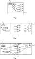
- FIG. 1 A snapshot of a wireless communication network with transmitting/receiving communication points (each communication point possess both features), together with obstacles obstructing a direct line-of-sight signal path inside a power converter cabinet, is illustrated in Fig. 1 .
- Different line types illustrate a set of different and possible signal propagation paths giving rise to the multipath channel behaviour.
- Fig. 1 there are several different propagation paths from one transmitting communication point 3a to the receiving communication point 2. Three different propagation paths are illustrated, one dotted, one dashed and one solid. This allows a communication link to be established despite lack of line-of-sight propagation between the respective communication points 2 and 3a. It is in contrast with the typical behaviour of mm-wave communication, where a direct line-of-sight link is expected.
- the antenna opening angle can, in principle, range from less than 1 degree to 360 degrees.
- the multipath characteristics of the channel is reduced to fluctuate less as a function of frequency (more flat).
- the transfer function variations increases as a function of frequency.
- a larger antenna opening angle also increases the possibility of increased external interference entering into the system. This in turn leads to the fact that the selection of the opening angle of the antenna is an important design decision.
- An opening angle of about 120 degrees allows a sufficient number of reflected rays to be received in the application and facilitates in establishing the communication link. If the opening angle is too small, like for instance below 20 degrees, a situation may occur where some locations (communication points) would not have coverage since there is no line-of-sight path, and the opening angle is too small to capture reflected rays. If the opening angle is too large, e.g. more than 180 degrees, a situation with too many reflections being received may occur, leading to an extreme multipath situation which is not resolvable even with advanced signal processing techniques. Utilization of an opening angle of between 70 and 150 degrees provides for a reasonable stability of the communication network.
- the signal processing techniques to be applied will depend on the multipath characteristics of the particular system scenario, which depends on e.g. the physical layout of the system, antenna characteristics, size of cabinet, type of components that represent the obstacles, number of obstacles.
- To facilitate proper reception it may e.g. be advantageous to include some training sequences for channel estimation and carrier recovery, carrier frequency and phase tracking. In some cases it may be sufficient with a simple equalizer or even no equalizer, and in other scenarios advanced modulation like Orthogonal Frequency Division Multiplexing (OFDM) or Code Division Multiple Access (CDMA), Spread Spectrum techniques or combinations of these techniques, possibly in combination with equalization techniques may be advantageous.
- Some scenarios may also advantageously include some form of diversity reception techniques in combination with advanced error control coding and/or hybrid Automatic Repeat request (ARQ) techniques.
- ARQ Automatic Repeat request
- the topology of the communication network may take different forms, including for instance a star network with a central unit and a number of nodes, or a ring network or a mesh network.
- Fig. 2 schematically illustrates a single cabinet 1 of a power converter.
- the communication network is used to provide high data-rate, several Gbits/s, information between a controller 5 and multiple power switches 6a-d. These power switches receive data to tell if they are to switch on or off, and to provide fast fault data back to the controller 5, or additionally adjacent power switches.
- the controller 5 is provided with a first communication point 2 and the power switches 6a-d are each provided with its own communication point 3a-d.
- Fig. 3 schematically illustrates multiple functional cabinets put together to form a power converter system within a closed cabinet 1.
- this system there may be multiple controllers 5, 7a-b and even redundant controllers 7a-b provided, in the left part of the cabinet 1.
- the wireless system is connected to the controllers. Wireless data is then sent to the power switches 6a-d, in the middle part of the cabinet 1, and also to sensors 8-10 in the right part of the cabinet.
- the sensors/measurement devices can be both high speed and low speed.
- the right part of the cabinet may comprise non-active components of the power converter such as inductors 8, capacitors 9 and mechanical switches 10.
- various signals e.g. voltages V, currents ⁇ , temperatures T, may be measured and transmitted back to the controllers 5, 7a-b.
- the controllers may also send commands to various actuators in the power converter to e.g. turn on and off fans, open and close contactors, etc. These actuators can receive and transmit both slow and high speed data.
- Fig. 4 schematically illustrates a redundant wireless system in place where data may be sent over different frequencies and different physical paths.
- the controllers 7a and 7b are two redundant controllers and the controller 5 is a supervising unit. Both of the two redundant controllers are able to receive data from the sensors e.g. high speed current sensor 8, and send switching data to the power switch 6a.
- One of the controllers e.g. 7a is the active controller and is controlling the switch 6a, while the other controller e.g. 7b is in active standby. If controller 7a fails then 7b may take over the control operation, either automatically or when commanded by the supervising controller e.g. 5.
- a power converter cabinet may include motor speed drives for pumping, traction, and marine applications. Furthermore, it may be used in static converters for wind turbines, excitation systems for power generation, etc.
- One of the power converter applications under consideration may call for a highly reliable communication with high data rate and low latency communication solutions.
- the required system features are provided by utilizing mm-wave wireless technology.
- the natural limitations (high attenuation, short-range, sever multipath propagation) of mm-wave technology can serve to be beneficial.
- control of a power switch mainly has been described above, sending of read/write data is equally applicable, for communication between active devices/components such as control units, power switches, sensors and actuators.
- the power switch may i.a. use the wireless communication to send data back, e.g. status information. Data may also be sent from a sensor back to the controller, or the controller may send a command signal to an actuator.
- the power converter cabinet 1 comprises at least a control unit 5 or 7a and 7b and at least a power switch 6a-d, a sensor 8-10 or an actuator.
- the communication network comprises: a first communication point 2, provided with a first antenna configured to wirelessly transmit/receive in the mm-wave frequency band, with an opening angle of between 20 and 180 degrees, wherein the first communication point 2 is connected to the at least a control unit 5 or 7a and 7b inside the power converter cabinet 1; and a second communication point 3a-d, provided with a second antenna configured to receive/transmit wirelessly in the mm-wave frequency band, with an opening angle of between 20 and 180 degrees, wherein the second communication point 3a-d is connected to the at least a power switch 6a-d, a sensor 8-10 or an actuator inside the power converter cabinet 1; wherein the first and second communication points are configured to set up a communication link with multiple propagation paths, to send data between different active devices and/or components inside the power converter cabinet 1.
- the mm-wave frequency band may be 30-300 GHz, preferably 40-100 GHz, and more preferably about 60 GHz.
- the opening angle may be between 70 and 150 degrees, and preferably about 120 degrees.
- the communication network may comprise a third communication point 3a-d, provided with a third antenna configured to receive/transmit wirelessly in the mm-wave frequency band, with an opening angle of between 20 and 180 degrees, wherein the first, second and third communication points are configured to set up communication links with multiple propagation paths, to send data between different active devices and/or components inside the power converter cabinet 1.
- the power converter cabinet 1 may be an at least partly closed cabinet in the sense that wireless mm-wave signals are reflected on its cabinet walls, wherein the cabinet walls may be of a metallic material, or of non-metallic material such as plastic materials, and/or with air gaps.
- a power converter cabinet which allows some RF signal to be received outside to enable communication to external nodes, e.g., mobile phones, smart devices, tablets etc. by having air gaps in the walls.
- the cabinet walls may still reflect some radio signals to improve communication inside the cabinet.
- the power converter cabinet 1 may comprise components and support structures being obstacles 4a-g for direct line-of-sight between two communication points 2, 3a-d and providing arbitrary reflection surfaces for the wireless mm-wave signals.
- a power converter cabinet 1 comprising at least a control unit 5; 7a-b and at least a power switch 6a-d, a sensor 8-10 or an actuator, and a communication network as described above.
- the power converter cabinet 1 comprises at least a control unit 5 or 7a and 7b and at least a power switch 6a-d, a sensor 8-10 or an actuator.
- the method comprises the steps of: arranging 20 a first communication point 2 inside the power converter cabinet 1, which first communication point 2 is configured to wirelessly transmit/receive in the mm-wave frequency band, with an opening angle of between 20 and 180 degrees, wherein the first communication point 2 is connected to the at least a control unit 5 or 7a and 7b inside the power converter cabinet 1; and arranging 21 a second communication point 3a-d inside the power converter cabinet 1, which second communication point 3a-d is configured to receive/transmit wirelessly in the mm-wave frequency band, with an opening angle of between 20 and 180 degrees, wherein the second communication point 3a-d is connected to the at least a power switch 6a-d, a sensor 8-10 or an actuator inside the power converter cabinet 1; wherein the first and second communication points are configured to send data between different active devices and/or components inside the power converter cabinet 1, with multiple propagation paths.
- the method may comprise the step of arranging 24 a third communication point 3a-d inside the power converter cabinet 1, which third communication point 3a-d is configured to receive/transmit wirelessly in the mm-wave frequency band, with an opening angle of between 20 and 180 degrees, wherein the first, second and third communication points are configured to send data between different active devices and/or components inside the power converter cabinet 1, with multiple propagation paths.
- the wireless mm-wave signals may be reflected on cabinet walls, wherein the cabinet walls may be of a metallic material facilitating reflection of mm-wave signals.
- the wireless mm-wave signals may be arbitrary reflected on components and support structures 4a-g inside the power converter cabinet 1, facilitating communication through multipath propagation inside the power converter cabinet.
Landscapes
- Engineering & Computer Science (AREA)
- Computer Networks & Wireless Communication (AREA)
- Signal Processing (AREA)
- Microelectronics & Electronic Packaging (AREA)
- Mobile Radio Communication Systems (AREA)
- Transmitters (AREA)
Description
- The invention relates to a communication network in a power converter cabinet. The invention also relates to a power converter cabinet and a method for communication within a power converter cabinet.
- Communication is an essential and integrated part of power converters. This communication needs to be robust and reliable, and with rather low latency. A control unit needs to communicate with several or even hundreds of units or more building blocks/cells/power modules. Communicating units may be placed at different potentials (several kilovolts plus), requiring electrical isolation between the transmitters and receivers.
- A traditional solution to this communication problem has been the use of optical fibres, which can provide sufficiently low latency, adequate data rates, and also electrical isolation. A problem with these optical components is that their performance deteriorates over time. Moreover, they also require substantial installation efforts, and some space for the cables which may not always be available, resulting in damage caused by excessive bending, etc.
- State of the art solutions typically apply
- fibre optics, which are expensive and deteriorate over time, and require time consuming installation
- other optical solutions like free-space optics alone or in combination with wired communications like for instance Ethernet or EtherCAT or similar, where the free space optics part provides the electrical isolation.
- Jong Ho Kim et al: "Antenna directivity effect on the delay spread at millimeter-wave", ADVANCED COMMUNICATION TECHNOLOGY (ICACT), 2011 13th International conference on, IEEE, (2011-02-13), pages 8-12, presents a delay spread characteristics at millimetre-wave band study.
- It has been proposed the use of wireless control of power network switching devices in
US2012207138 . - An object of the present invention is to improve communication reliability for power converters inside a cabinet.
- According to a first aspect, it is presented a communication network in a power converter cabinet. The power converter cabinet comprises at least a control unit and at least a power switch, a sensor or an actuator. The communication network comprises: a first communication point, provided with a first antenna configured to wirelessly transmit/receive in the mm-wave frequency band, with an opening angle of between 20 and 180 degrees, wherein the first communication point is connected to the at least a control unit inside the power converter cabinet; and a second communication point, provided with a second antenna configured to receive/transmit wirelessly in the mm-wave frequency band, with an opening angle of between 20 and 180 degrees, wherein the second communication point is connected to the at least a power switch, a sensor or an actuator inside the power converter cabinet; wherein the first and second communication points are configured to set up a communication link with multiple propagation paths, to send data between different active devices and/or components inside the power converter cabinet.
- The mm-wave frequency band may be 30-300 GHz, preferably 40-100 GHz, and more preferably about 60 GHz.
- The opening angle may be between 70 and 150 degrees, and preferably about 120 degrees.
- The communication network may comprise a third communication point, provided with a third antenna configured to receive/transmit wirelessly in the mm-wave frequency band, with an opening angle of between 20 and 180 degrees, wherein the first, second and third communication points are configured to set up communication links with multiple propagation paths, to send data between different active devices and/or components inside the power converter cabinet.
- The cabinet may be an at least partly closed cabinet in the sense that wireless mm-wave signals are reflected on its cabinet walls, wherein the cabinet walls may be metallic.
- The cabinet may comprise components and support structures being obstacles for direct line-of-sight between two communication points and providing arbitrary reflection surfaces for the wireless mm-wave signals.
- According to a second aspect, it is presented a power converter cabinet, comprising at least a control unit and at least a power switch, a sensor or an actuator, and a communication network according to the first aspect above.
- According to a third aspect, it is presented a method for communication within an at least partly closed power converter cabinet, wherein the power converter cabinet comprises at least a control unit and at least a power switch, a sensor or an actuator. The method comprises the steps of: arranging a first communication point inside the power converter cabinet, which first communication point is configured to wirelessly transmit/receive in the mm-wave frequency band, with an opening angle of between 20 and 180 degrees, wherein the first communication point is connected to the at least a control unit inside the power converter cabinet; and arranging a second communication point inside the power converter cabinet, which second communication point is configured to receive/transmit wirelessly in the mm-wave frequency band, with an opening angle of between 20 and 180 degrees, wherein the second communication point is connected to the at least a power switch, a sensor or an actuator inside the power converter cabinet; wherein the first and second communication points are configured to send data between different active devices and/or components inside the power converter cabinet, with multiple propagation paths.
- The method may comprise the step of arranging a third communication point inside the power converter cabinet, which third communication point is configured to receive/transmit wirelessly in the mm-wave frequency band, with an opening angle of between 20 and 180 degrees, wherein the first, second and third communication points are configured to send data between different active devices and/or components inside the power converter cabinet, with multiple propagation paths.
- Generally, all terms used in the claims are to be interpreted according to their ordinary meaning in the technical field, unless explicitly defined otherwise herein. All references to "a/an/the element, apparatus, component, means, step, etc." are to be interpreted openly as referring to at least one instance of the element, apparatus, component, means, step, etc., unless explicitly stated otherwise. The steps of any method disclosed herein do not have to be performed in the exact order disclosed, unless explicitly stated.
- The invention is now described, by way of example, with reference to the accompanying drawings, in which:
-
Fig. 1 schematically illustrates multi propagation paths inside a cabinet. -
Fig. 2 schematically illustrates a cabinet according to an embodiment of the description. -
Fig. 3 schematically illustrates a cabinet according to an embodiment of the description. -
Fig. 4 schematically illustrates a cabinet according to an embodiment of the description. -
Fig. 5 illustrates the steps of a method according to an embodiment of the description. - The invention will now be described more fully hereinafter with reference to the accompanying drawings, in which certain embodiments of the invention are shown. This invention may, however, be embodied in many different forms and should not be construed as limited to the embodiments set forth herein; rather, these embodiments are provided by way of example so that this disclosure will be thorough and complete, and will fully convey the scope of the invention to those skilled in the art. Like numbers refer to like elements throughout the description.
- The basic idea of the present invention is to utilize non-line-of-sight propagation with millimetre wave radio for time-critical communication in power converter applications.
- A solution to time-critical communication in power converter applications could be to apply wireless communication using electromagnetic wave propagation. However, well-known wireless standards or wireless technologies at ISM bands (for Industrial, Scientific and Medical purposes other than telecommunication) cannot easily fulfil the requirements for this rather critical application. In addition, such frequency bands are almost everywhere in the world overcrowded, and thus there is both a capacity problem and a severe interference problem with using that band. To avoid interference into power converter systems with possible errors in the communication causing retransmissions and delays, and also to avoid causing interference to other systems, the present invention uses mm-wave frequencies (i.e., 30 - 300 GHz) for this application. At such frequencies there is a huge amount of bandwidth available, more or less license free. Another advantage is that at such high frequencies, the attenuation is rather high, which is beneficial in terms of interference avoidance to and from the power converter system. A reasonable mm-wave frequency is between 40-100 GHz. The attenuation is especially high around 60 GHz due to oxygen absorption. The atmospheric absorption at 60GHz is a slightly above 10dB/km in a band around 60 GHz. It can be as high as 15dB/km exactly at 60GHz due to oxygen resonance.
- However, applying mm-wave communication in power electronics applications has some challenges. The transmitter and receiver cannot be expected to have line-of-sight between them. This is because there are a lot of metallic objects, transformers, capacitors, and other power electronic components obstructing the signal propagation between transmitter and receiver. Thus, in power converter applications we cannot rely on narrow antenna beams and direct line-of-sight communication as is often the case in mm-wave communication.
- In an environment with lots of reflecting objects, the resulting signal at a receiver will contain delayed and attenuated replicas of the transmitted signal. This will give a channel transfer function that varies greatly with frequency. For some frequencies and distances the signal components add constructively, whereas at other distances and frequencies the signal will add destructively as the signal components experience different phase shifts. This appears in the channel transfer function as tops (high gains) and zeros (or dips with very low gain). Such behaviour for the channel transfer function has been verified with both finite element calculations and with on-site measurements.
- To achieve high reliability, high capacity, and short latency wireless communication inside a power converter cabinet, mm-wave frequency bands are used having non-line-of-sight communication, and antennas are used with appropriate opening angles. The cabinet have obstructing and reflecting metallic as well as non-metallic objects that in general obstruct the line-of-sight between two communication points.
- The benefit of the present invention summarizes electrical isolation between nodes, or communication points, high capacity wireless communication possible due to many GHz of available bandwidth, low latency communication due to high data rate (Gbits/s), and limited retransmission due to low interference, flexible low cost installation, only logical connections established by system designer (not during deployment), and antenna orientation is not critical, limited interference from external systems due to high attenuation at mm-waves, and especially for frequencies around 60 GHz, gives high reliability, limited interference to other systems due to high attenuation, practically license-free operation, and flexible network topology possible, including, but not limited to, star topology (point to multipoint).
- In
Figure 1 , it is schematically illustrated a communication scenario with several communication points. Each of these communication points communicates with one or several of the other communication points in the network using mm-wave wireless communication and antennas with a certain opening angle to allow non-line-of-sight communication. The wireless transmitters and receivers in the network use for instance a point-to-multipoint communication to serve all units or communication points in a flexible way. - The opening angles in this application are for a wide-beam patch antenna. For other types of antennas the same beam width may be provided with other definitions of opening angles.
- Arranging of communication points are arbitrarily selected from a radio propagation point of view. A design goal is to place the antenna as close as possible to node with communication need, preferably on the node.
- A snapshot of a wireless communication network with transmitting/receiving communication points (each communication point possess both features), together with obstacles obstructing a direct line-of-sight signal path inside a power converter cabinet, is illustrated in
Fig. 1 . Different line types illustrate a set of different and possible signal propagation paths giving rise to the multipath channel behaviour. - As illustrated in the example of
Fig. 1 , there are several different propagation paths from one transmittingcommunication point 3a to the receivingcommunication point 2. Three different propagation paths are illustrated, one dotted, one dashed and one solid. This allows a communication link to be established despite lack of line-of-sight propagation between therespective communication points - Inside the power converter cabinet, under non-line-of-sight propagation conditions, the communication is possible as long as the antenna opening angle is sufficiently large to receive reflected waves. Note that the antenna opening angle can, in principle, range from less than 1 degree to 360 degrees. By having very narrow beams with reduced opening angle of the antenna, the multipath characteristics of the channel is reduced to fluctuate less as a function of frequency (more flat). In this situation, there is a risk of not being able to establish connections between communication points with many obstacles between them. By increasing the opening angle of the antenna, it is easier to establish connections, but at the same time the transfer function variations increases as a function of frequency. A larger antenna opening angle also increases the possibility of increased external interference entering into the system. This in turn leads to the fact that the selection of the opening angle of the antenna is an important design decision.
- An opening angle of about 120 degrees allows a sufficient number of reflected rays to be received in the application and facilitates in establishing the communication link. If the opening angle is too small, like for instance below 20 degrees, a situation may occur where some locations (communication points) would not have coverage since there is no line-of-sight path, and the opening angle is too small to capture reflected rays. If the opening angle is too large, e.g. more than 180 degrees, a situation with too many reflections being received may occur, leading to an extreme multipath situation which is not resolvable even with advanced signal processing techniques. Utilization of an opening angle of between 70 and 150 degrees provides for a reasonable stability of the communication network.
- The signal processing techniques to be applied will depend on the multipath characteristics of the particular system scenario, which depends on e.g. the physical layout of the system, antenna characteristics, size of cabinet, type of components that represent the obstacles, number of obstacles. To facilitate proper reception it may e.g. be advantageous to include some training sequences for channel estimation and carrier recovery, carrier frequency and phase tracking. In some cases it may be sufficient with a simple equalizer or even no equalizer, and in other scenarios advanced modulation like Orthogonal Frequency Division Multiplexing (OFDM) or Code Division Multiple Access (CDMA), Spread Spectrum techniques or combinations of these techniques, possibly in combination with equalization techniques may be advantageous. Some scenarios may also advantageously include some form of diversity reception techniques in combination with advanced error control coding and/or hybrid Automatic Repeat request (ARQ) techniques.
- The topology of the communication network may take different forms, including for instance a star network with a central unit and a number of nodes, or a ring network or a mesh network.
- Due to the antenna characteristics (frequency and opening angle), multiple propagation paths and obstructing/reflecting objects, communication is established even without line-of-sight between the transmitting and receiving
communication points - Possible application scenario examples of the present invention are described in connection with
Figs. 2-4 . -
Fig. 2 schematically illustrates asingle cabinet 1 of a power converter. In this case the communication network is used to provide high data-rate, several Gbits/s, information between acontroller 5 andmultiple power switches 6a-d. These power switches receive data to tell if they are to switch on or off, and to provide fast fault data back to thecontroller 5, or additionally adjacent power switches. Thecontroller 5 is provided with afirst communication point 2 and the power switches 6a-d are each provided with itsown communication point 3a-d. -
Fig. 3 schematically illustrates multiple functional cabinets put together to form a power converter system within aclosed cabinet 1. In this system, there may bemultiple controllers redundant controllers 7a-b provided, in the left part of thecabinet 1. Here the wireless system is connected to the controllers. Wireless data is then sent to the power switches 6a-d, in the middle part of thecabinet 1, and also to sensors 8-10 in the right part of the cabinet. The sensors/measurement devices can be both high speed and low speed. - The right part of the cabinet may comprise non-active components of the power converter such as
inductors 8,capacitors 9 andmechanical switches 10. As part of the overall control process various signals, e.g. voltages V, currents ±, temperatures T, may be measured and transmitted back to thecontrollers -
Fig. 4 schematically illustrates a redundant wireless system in place where data may be sent over different frequencies and different physical paths. In this case thecontrollers controller 5 is a supervising unit. Both of the two redundant controllers are able to receive data from the sensors e.g. high speedcurrent sensor 8, and send switching data to thepower switch 6a. One of the controllers e.g. 7a is the active controller and is controlling theswitch 6a, while the other controller e.g. 7b is in active standby. Ifcontroller 7a fails then 7b may take over the control operation, either automatically or when commanded by the supervising controller e.g. 5. - Applications of a power converter cabinet may include motor speed drives for pumping, traction, and marine applications. Furthermore, it may be used in static converters for wind turbines, excitation systems for power generation, etc.
- One of the power converter applications under consideration may call for a highly reliable communication with high data rate and low latency communication solutions. In this invention, the required system features are provided by utilizing mm-wave wireless technology. In addition to the huge available license free bandwidth, the natural limitations (high attenuation, short-range, sever multipath propagation) of mm-wave technology can serve to be beneficial.
- Although control of a power switch mainly has been described above, sending of read/write data is equally applicable, for communication between active devices/components such as control units, power switches, sensors and actuators. The power switch may i.a. use the wireless communication to send data back, e.g. status information. Data may also be sent from a sensor back to the controller, or the controller may send a command signal to an actuator.
- A communication network in a
power converter cabinet 1 is next presented in a more general way with reference toFigs. 1-4 . Thepower converter cabinet 1 comprises at least acontrol unit power switch 6a-d, a sensor 8-10 or an actuator. The communication network comprises: afirst communication point 2, provided with a first antenna configured to wirelessly transmit/receive in the mm-wave frequency band, with an opening angle of between 20 and 180 degrees, wherein thefirst communication point 2 is connected to the at least acontrol unit power converter cabinet 1; and asecond communication point 3a-d, provided with a second antenna configured to receive/transmit wirelessly in the mm-wave frequency band, with an opening angle of between 20 and 180 degrees, wherein thesecond communication point 3a-d is connected to the at least apower switch 6a-d, a sensor 8-10 or an actuator inside thepower converter cabinet 1; wherein the first and second communication points are configured to set up a communication link with multiple propagation paths, to send data between different active devices and/or components inside thepower converter cabinet 1. - The mm-wave frequency band may be 30-300 GHz, preferably 40-100 GHz, and more preferably about 60 GHz.
- The opening angle may be between 70 and 150 degrees, and preferably about 120 degrees.
- The communication network may comprise a
third communication point 3a-d, provided with a third antenna configured to receive/transmit wirelessly in the mm-wave frequency band, with an opening angle of between 20 and 180 degrees, wherein the first, second and third communication points are configured to set up communication links with multiple propagation paths, to send data between different active devices and/or components inside thepower converter cabinet 1. - The
power converter cabinet 1 may be an at least partly closed cabinet in the sense that wireless mm-wave signals are reflected on its cabinet walls, wherein the cabinet walls may be of a metallic material, or of non-metallic material such as plastic materials, and/or with air gaps. - It is foreseen to have a power converter cabinet which allows some RF signal to be received outside to enable communication to external nodes, e.g., mobile phones, smart devices, tablets etc. by having air gaps in the walls. However, the cabinet walls may still reflect some radio signals to improve communication inside the cabinet.
- The
power converter cabinet 1 may comprise components and supportstructures being obstacles 4a-g for direct line-of-sight between twocommunication points - A
power converter cabinet 1 is presented, comprising at least acontrol unit 5; 7a-b and at least apower switch 6a-d, a sensor 8-10 or an actuator, and a communication network as described above. - A method for communication within an at least partly closed
power converter cabinet 1 is presented with reference toFig. 5 . Thepower converter cabinet 1 comprises at least acontrol unit power switch 6a-d, a sensor 8-10 or an actuator. The method comprises the steps of: arranging 20 afirst communication point 2 inside thepower converter cabinet 1, whichfirst communication point 2 is configured to wirelessly transmit/receive in the mm-wave frequency band, with an opening angle of between 20 and 180 degrees, wherein thefirst communication point 2 is connected to the at least acontrol unit power converter cabinet 1; and arranging 21 asecond communication point 3a-d inside thepower converter cabinet 1, whichsecond communication point 3a-d is configured to receive/transmit wirelessly in the mm-wave frequency band, with an opening angle of between 20 and 180 degrees, wherein thesecond communication point 3a-d is connected to the at least apower switch 6a-d, a sensor 8-10 or an actuator inside thepower converter cabinet 1; wherein the first and second communication points are configured to send data between different active devices and/or components inside thepower converter cabinet 1, with multiple propagation paths. - The method may comprise the step of arranging 24 a
third communication point 3a-d inside thepower converter cabinet 1, whichthird communication point 3a-d is configured to receive/transmit wirelessly in the mm-wave frequency band, with an opening angle of between 20 and 180 degrees, wherein the first, second and third communication points are configured to send data between different active devices and/or components inside thepower converter cabinet 1, with multiple propagation paths. - The wireless mm-wave signals may be reflected on cabinet walls, wherein the cabinet walls may be of a metallic material facilitating reflection of mm-wave signals.
- The wireless mm-wave signals may be arbitrary reflected on components and
support structures 4a-g inside thepower converter cabinet 1, facilitating communication through multipath propagation inside the power converter cabinet. - The invention has mainly been described above with reference to a few embodiments. However, as is readily appreciated by a person skilled in the art, other embodiments than the ones disclosed above are equally possible within the scope of the invention, as defined by the appended patent claims.
Claims (15)
- A communication network in a power converter cabinet (1), wherein the power converter cabinet (1) comprises at least a control unit (5; 7a, 7b) and at least a power switch (6a-d), a sensor (8-10) or an actuator, the communication network comprises:a first communication point (2), provided with a first antenna configured to wirelessly transmit/receive in the mm-wave frequency band, with an opening angle of between 20 and 180 degrees, wherein the first communication point (2) is connected to the at least a control unit (5; 7a, 7b) inside the power converter cabinet (1); anda second communication point (3a-d), provided with a second antenna configured to receive/transmit wirelessly in the mm-wave frequency band, with an opening angle of between 20 and 180 degrees, wherein the second communication point (3a-d) is connected to the at least a power switch (6a-d), a sensor (8-10) or an actuator inside the power converter cabinet (1);wherein the first and second communication points are configured to set up a communication link with multiple propagation paths, to send data between different active devices and/or components inside the power converter cabinet (1).
- The communication network according to claim 1, wherein the mm-wave frequency band is 30-300 GHz, preferably 40-100 GHz, and more preferably about 60 GHz.
- The communication network according to any one of claims 1-2, wherein the opening angle is between 70 and 150 degrees, and preferably about 120 degrees.
- The communication network according to any one of claims 1-3, comprising a third communication point (3a-d), provided with a third antenna configured to receive/transmit wirelessly in the mm-wave frequency band, with an opening angle of between 20 and 180 degrees, wherein the first, second and third communication points are configured to set up communication links with multiple propagation paths, to send data between different active devices and/or components inside the power converter cabinet (1).
- The communication network according to any one of claims 1-4, wherein the power converter cabinet (1) is an at least partly closed cabinet in the sense that wireless mm-wave signals are reflected on its cabinet walls.
- The communication network according to claim 5, wherein the cabinet walls are metallic.
- The communication network according to any one of claims 1-6, wherein the power converter cabinet (1) comprises components and support structures being obstacles (4a-g) for direct line-of-sight between two communication points (2, 3a-d) and providing arbitrary reflection surfaces for the wireless mm-wave signals.
- A power converter cabinet (1), comprising at least a control unit (5; 7a-b) and at least a power switch (6a-d), a sensor (8-10) or an actuator, and a communication network according to any one of claims 1-7.
- A method for communication within an at least partly closed power converter cabinet (1), wherein the power converter cabinet (1) comprises at least a control unit (5; 7a, 7b) and at least a power switch (6a-d), a sensor (8-10) or an actuator, the method comprising the steps of:arranging (20) a first communication point (2) inside the power converter cabinet (1), which first communication point (2) is configured to wirelessly transmit/receive in the mm-wave frequency band, with an opening angle of between 20 and 180 degrees, wherein the first communication point (2) is connected to the at least a control unit (5; 7a, 7b) inside the power converter cabinet (1); andarranging (21) a second communication point (3a-d) inside the power converter cabinet (1), which second communication point (3a-d) is configured to receive/transmit wirelessly in the mm-wave frequency band, with an opening angle of between 20 and 180 degrees, wherein the second communication point (3a-d) is connected to the at least a power switch (6a-d), a sensor (8-10) or an actuator inside the power converter cabinet (1);wherein the first and second communication points are configured to send data between different active devices and/or components inside the power converter cabinet (1), with multiple propagation paths.
- The method according to claim 9, wherein the mm-wave frequency band is 30-300 GHz, preferably 40-100 GHz, and more preferably about 60 GHz.
- The method according to any one of claims 9-10, wherein the opening angle is between 70 and 150 degrees, and preferably about 120 degrees.
- The method according to any one of claims 9-11, comprising the step of arranging (24) a third communication point (3a-d) inside the power converter cabinet (1), which third communication point (3a-d) is configured to receive/transmit wirelessly in the mm-wave frequency band, with an opening angle of between 20 and 180 degrees, wherein the first, second and third communication points are configured to send data between different active devices and/or components inside the power converter cabinet (1), with multiple propagation paths.
- The method according to any one of claims 9-12, wherein the wireless mm-wave signals are reflected on cabinet walls.
- The method according to claim 13, wherein the cabinet walls are metallic.
- The method according to any one of claims 9-14, wherein the wireless mm-wave signals are arbitrary reflected on components and support structures (4a-g) inside the power converter cabinet (1).
Applications Claiming Priority (2)
| Application Number | Priority Date | Filing Date | Title |
|---|---|---|---|
| EP15164630.4A EP3086486A1 (en) | 2015-04-22 | 2015-04-22 | A communication network, a power converter cabinet and a method therefore |
| PCT/EP2016/057510 WO2016169769A1 (en) | 2015-04-22 | 2016-04-06 | A communication network, a power converter cabinet and a method therefore |
Publications (2)
| Publication Number | Publication Date |
|---|---|
| EP3286852A1 EP3286852A1 (en) | 2018-02-28 |
| EP3286852B1 true EP3286852B1 (en) | 2019-03-06 |
Family
ID=53008314
Family Applications (2)
| Application Number | Title | Priority Date | Filing Date |
|---|---|---|---|
| EP15164630.4A Withdrawn EP3086486A1 (en) | 2015-04-22 | 2015-04-22 | A communication network, a power converter cabinet and a method therefore |
| EP16714886.5A Active EP3286852B1 (en) | 2015-04-22 | 2016-04-06 | A communication network, a power converter cabinet and a method therefore |
Family Applications Before (1)
| Application Number | Title | Priority Date | Filing Date |
|---|---|---|---|
| EP15164630.4A Withdrawn EP3086486A1 (en) | 2015-04-22 | 2015-04-22 | A communication network, a power converter cabinet and a method therefore |
Country Status (4)
| Country | Link |
|---|---|
| US (1) | US10171977B2 (en) |
| EP (2) | EP3086486A1 (en) |
| CN (1) | CN107534458B (en) |
| WO (1) | WO2016169769A1 (en) |
Families Citing this family (5)
| Publication number | Priority date | Publication date | Assignee | Title |
|---|---|---|---|---|
| EP3086486A1 (en) | 2015-04-22 | 2016-10-26 | ABB Technology Ltd | A communication network, a power converter cabinet and a method therefore |
| CN111373700B (en) * | 2017-10-31 | 2021-11-19 | 村田机械株式会社 | Communication system, controlled device, and control method of communication system |
| CN110474690A (en) * | 2018-05-11 | 2019-11-19 | 中山市明阳电器有限公司 | A kind of optic communication wireless networking arrangement and method applied to drawer-type switch cabinet |
| DE102020121271A1 (en) | 2020-08-13 | 2022-02-17 | Schaeffler Technologies AG & Co. KG | Machine and method for sending and/or receiving machine-specific data of the machine |
| CN118714020B (en) * | 2024-08-21 | 2024-12-06 | 浙江大学 | Computer network system and computer system |
Family Cites Families (16)
| Publication number | Priority date | Publication date | Assignee | Title |
|---|---|---|---|---|
| JPH0951293A (en) | 1995-05-30 | 1997-02-18 | Matsushita Electric Ind Co Ltd | Indoor wireless communication system |
| US7065326B2 (en) * | 2001-05-02 | 2006-06-20 | Trex Enterprises Corporation | Millimeter wave communications system with a high performance modulator circuit |
| US7113134B1 (en) | 2004-03-12 | 2006-09-26 | Current Technologies, Llc | Transformer antenna device and method of using the same |
| US7551680B2 (en) * | 2004-10-28 | 2009-06-23 | Interdigital Technology Corporation | Wireless communication method and apparatus for forming, steering and selectively receiving a sufficient number of usable beam paths in both azimuth and elevation |
| DE602006020785D1 (en) | 2006-05-23 | 2011-04-28 | Intel Corp | MILLIMETER WAVE COMMUNICATION SYSTEM FOR THE INTERIOR |
| WO2009002464A2 (en) * | 2007-06-22 | 2008-12-31 | Vubiq Incorporated | System and method for wireless communication in a backplane fabric architecture |
| US8897184B2 (en) * | 2007-06-22 | 2014-11-25 | Vubiq Networks, Inc. | System and method for wireless communication in a backplane fabric architecture |
| US20090323860A1 (en) * | 2008-06-27 | 2009-12-31 | Infineon Technologies Ag | Receiving and processing data |
| FR2939991A1 (en) | 2008-12-11 | 2010-06-18 | Canon Kk | METHOD FOR SELECTING AN EFFECTIVE RECEPTION ANGLE OF A DIRECTIONAL ANTENNA OF A RECEIVER NODE, COMPUTER PROGRAM PRODUCT, STORAGE MEDIUM, AND RECEIVER NODE |
| US8326221B2 (en) * | 2009-02-09 | 2012-12-04 | Apple Inc. | Portable electronic device with proximity-based content synchronization |
| CN102577075B (en) | 2009-10-14 | 2016-06-01 | Abb研究有限公司 | Wireless Control of Power Network Switching Devices |
| US8797211B2 (en) | 2011-02-10 | 2014-08-05 | International Business Machines Corporation | Millimeter-wave communications using a reflector |
| EP2737718B1 (en) * | 2011-07-29 | 2019-09-04 | Vubiq Networks Inc. | System and method for wireless communication in a backplane fabric architecture |
| US9281979B2 (en) | 2013-02-26 | 2016-03-08 | Intel Corporation | Millimeter-wave line of sight MIMO communication system for indoor applications |
| CN203554264U (en) * | 2013-11-06 | 2014-04-16 | 广西电网公司电力科学研究院 | Modularized bidirectional energy-storage current transformer cabinet |
| EP3086486A1 (en) | 2015-04-22 | 2016-10-26 | ABB Technology Ltd | A communication network, a power converter cabinet and a method therefore |
-
2015
- 2015-04-22 EP EP15164630.4A patent/EP3086486A1/en not_active Withdrawn
-
2016
- 2016-04-06 US US15/563,149 patent/US10171977B2/en active Active
- 2016-04-06 EP EP16714886.5A patent/EP3286852B1/en active Active
- 2016-04-06 WO PCT/EP2016/057510 patent/WO2016169769A1/en not_active Ceased
- 2016-04-06 CN CN201680023123.4A patent/CN107534458B/en active Active
Non-Patent Citations (1)
| Title |
|---|
| None * |
Also Published As
| Publication number | Publication date |
|---|---|
| EP3286852A1 (en) | 2018-02-28 |
| CN107534458A (en) | 2018-01-02 |
| WO2016169769A1 (en) | 2016-10-27 |
| EP3086486A1 (en) | 2016-10-26 |
| US20180091931A1 (en) | 2018-03-29 |
| CN107534458B (en) | 2019-07-09 |
| US10171977B2 (en) | 2019-01-01 |
Similar Documents
| Publication | Publication Date | Title |
|---|---|---|
| US10171977B2 (en) | Communication network, a power converter cabinet, and a method therefore | |
| Wang et al. | Beam codebook based beamforming protocol for multi-Gbps millimeter-wave WPAN systems | |
| JP5424086B2 (en) | Wireless communication system, transmission terminal, reception terminal, and data retransmission method | |
| WO2021252858A1 (en) | Relay-aided intelligent reconfigurable surfaces | |
| US9762296B2 (en) | Wireless communication system | |
| CN109906560B (en) | Vehicle performing wireless communication and communication method thereof | |
| US12244368B2 (en) | Reflection direction control method, reflection direction control system, reflection direction control device, and reflection direction control program | |
| US20230209510A1 (en) | Radio communication method, radio communication system, radio base station, and repeater | |
| CN113812097B (en) | Multiple-input multiple-output transmission and reception | |
| CN103404044B (en) | A kind of antenna adjusting method of multiple-input and multiple-output microwave system and device | |
| Shaddad et al. | Channel estimation for intelligent reflecting surface in 6G wireless network via deep learning technique | |
| US12512888B2 (en) | Method and device for beam training for an intelligent reflecting surface (IRS) assisted cellular system | |
| EP4677757A1 (en) | Horizontal and vertical beamforming design for irs-assisted communications | |
| CN106465146A (en) | Electrically adjustable antenna, base station and method for matching RCU and RF port | |
| EP4252358A1 (en) | Polarization based beam selection process | |
| WO2019176388A1 (en) | Wireless communication system, wireless communication device, wireless communication method, and non-transitory computer-readable medium | |
| US20250125844A1 (en) | Control methods, communication devices and programs | |
| Madhow | Networking at 60 GHz: The emergence of multigigabit wireless | |
| WO2012156276A1 (en) | Transmission line and passenger information system | |
| EP3706326B1 (en) | Communication device for communicating between a power equipment controller and power equipment devices | |
| CN112886998A (en) | Microwave transmission method and related equipment | |
| JP5156676B2 (en) | Transmitting station | |
| US10666333B2 (en) | Signal transmission diversity | |
| CN116896696A (en) | Host-based optical frequency tuning | |
| WO2025074622A1 (en) | Communication system and time estimation method |
Legal Events
| Date | Code | Title | Description |
|---|---|---|---|
| STAA | Information on the status of an ep patent application or granted ep patent |
Free format text: STATUS: THE INTERNATIONAL PUBLICATION HAS BEEN MADE |
|
| PUAI | Public reference made under article 153(3) epc to a published international application that has entered the european phase |
Free format text: ORIGINAL CODE: 0009012 |
|
| STAA | Information on the status of an ep patent application or granted ep patent |
Free format text: STATUS: REQUEST FOR EXAMINATION WAS MADE |
|
| 17P | Request for examination filed |
Effective date: 20171122 |
|
| AK | Designated contracting states |
Kind code of ref document: A1 Designated state(s): AL AT BE BG CH CY CZ DE DK EE ES FI FR GB GR HR HU IE IS IT LI LT LU LV MC MK MT NL NO PL PT RO RS SE SI SK SM TR |
|
| AX | Request for extension of the european patent |
Extension state: BA ME |
|
| DAV | Request for validation of the european patent (deleted) | ||
| DAX | Request for extension of the european patent (deleted) | ||
| GRAP | Despatch of communication of intention to grant a patent |
Free format text: ORIGINAL CODE: EPIDOSNIGR1 |
|
| STAA | Information on the status of an ep patent application or granted ep patent |
Free format text: STATUS: GRANT OF PATENT IS INTENDED |
|
| INTG | Intention to grant announced |
Effective date: 20181126 |
|
| GRAS | Grant fee paid |
Free format text: ORIGINAL CODE: EPIDOSNIGR3 |
|
| GRAA | (expected) grant |
Free format text: ORIGINAL CODE: 0009210 |
|
| STAA | Information on the status of an ep patent application or granted ep patent |
Free format text: STATUS: THE PATENT HAS BEEN GRANTED |
|
| AK | Designated contracting states |
Kind code of ref document: B1 Designated state(s): AL AT BE BG CH CY CZ DE DK EE ES FI FR GB GR HR HU IE IS IT LI LT LU LV MC MK MT NL NO PL PT RO RS SE SI SK SM TR |
|
| REG | Reference to a national code |
Ref country code: GB Ref legal event code: FG4D |
|
| REG | Reference to a national code |
Ref country code: CH Ref legal event code: EP Ref country code: AT Ref legal event code: REF Ref document number: 1105976 Country of ref document: AT Kind code of ref document: T Effective date: 20190315 |
|
| REG | Reference to a national code |
Ref country code: DE Ref legal event code: R096 Ref document number: 602016010729 Country of ref document: DE |
|
| REG | Reference to a national code |
Ref country code: IE Ref legal event code: FG4D |
|
| REG | Reference to a national code |
Ref country code: NL Ref legal event code: MP Effective date: 20190306 |
|
| REG | Reference to a national code |
Ref country code: LT Ref legal event code: MG4D |
|
| PG25 | Lapsed in a contracting state [announced via postgrant information from national office to epo] |
Ref country code: LT Free format text: LAPSE BECAUSE OF FAILURE TO SUBMIT A TRANSLATION OF THE DESCRIPTION OR TO PAY THE FEE WITHIN THE PRESCRIBED TIME-LIMIT Effective date: 20190306 Ref country code: NO Free format text: LAPSE BECAUSE OF FAILURE TO SUBMIT A TRANSLATION OF THE DESCRIPTION OR TO PAY THE FEE WITHIN THE PRESCRIBED TIME-LIMIT Effective date: 20190606 Ref country code: SE Free format text: LAPSE BECAUSE OF FAILURE TO SUBMIT A TRANSLATION OF THE DESCRIPTION OR TO PAY THE FEE WITHIN THE PRESCRIBED TIME-LIMIT Effective date: 20190306 Ref country code: FI Free format text: LAPSE BECAUSE OF FAILURE TO SUBMIT A TRANSLATION OF THE DESCRIPTION OR TO PAY THE FEE WITHIN THE PRESCRIBED TIME-LIMIT Effective date: 20190306 |
|
| PG25 | Lapsed in a contracting state [announced via postgrant information from national office to epo] |
Ref country code: LV Free format text: LAPSE BECAUSE OF FAILURE TO SUBMIT A TRANSLATION OF THE DESCRIPTION OR TO PAY THE FEE WITHIN THE PRESCRIBED TIME-LIMIT Effective date: 20190306 Ref country code: RS Free format text: LAPSE BECAUSE OF FAILURE TO SUBMIT A TRANSLATION OF THE DESCRIPTION OR TO PAY THE FEE WITHIN THE PRESCRIBED TIME-LIMIT Effective date: 20190306 Ref country code: BG Free format text: LAPSE BECAUSE OF FAILURE TO SUBMIT A TRANSLATION OF THE DESCRIPTION OR TO PAY THE FEE WITHIN THE PRESCRIBED TIME-LIMIT Effective date: 20190606 Ref country code: GR Free format text: LAPSE BECAUSE OF FAILURE TO SUBMIT A TRANSLATION OF THE DESCRIPTION OR TO PAY THE FEE WITHIN THE PRESCRIBED TIME-LIMIT Effective date: 20190607 Ref country code: NL Free format text: LAPSE BECAUSE OF FAILURE TO SUBMIT A TRANSLATION OF THE DESCRIPTION OR TO PAY THE FEE WITHIN THE PRESCRIBED TIME-LIMIT Effective date: 20190306 Ref country code: HR Free format text: LAPSE BECAUSE OF FAILURE TO SUBMIT A TRANSLATION OF THE DESCRIPTION OR TO PAY THE FEE WITHIN THE PRESCRIBED TIME-LIMIT Effective date: 20190306 |
|
| REG | Reference to a national code |
Ref country code: AT Ref legal event code: MK05 Ref document number: 1105976 Country of ref document: AT Kind code of ref document: T Effective date: 20190306 |
|
| PG25 | Lapsed in a contracting state [announced via postgrant information from national office to epo] |
Ref country code: ES Free format text: LAPSE BECAUSE OF FAILURE TO SUBMIT A TRANSLATION OF THE DESCRIPTION OR TO PAY THE FEE WITHIN THE PRESCRIBED TIME-LIMIT Effective date: 20190306 Ref country code: PT Free format text: LAPSE BECAUSE OF FAILURE TO SUBMIT A TRANSLATION OF THE DESCRIPTION OR TO PAY THE FEE WITHIN THE PRESCRIBED TIME-LIMIT Effective date: 20190706 Ref country code: AL Free format text: LAPSE BECAUSE OF FAILURE TO SUBMIT A TRANSLATION OF THE DESCRIPTION OR TO PAY THE FEE WITHIN THE PRESCRIBED TIME-LIMIT Effective date: 20190306 Ref country code: SK Free format text: LAPSE BECAUSE OF FAILURE TO SUBMIT A TRANSLATION OF THE DESCRIPTION OR TO PAY THE FEE WITHIN THE PRESCRIBED TIME-LIMIT Effective date: 20190306 Ref country code: IT Free format text: LAPSE BECAUSE OF FAILURE TO SUBMIT A TRANSLATION OF THE DESCRIPTION OR TO PAY THE FEE WITHIN THE PRESCRIBED TIME-LIMIT Effective date: 20190306 Ref country code: EE Free format text: LAPSE BECAUSE OF FAILURE TO SUBMIT A TRANSLATION OF THE DESCRIPTION OR TO PAY THE FEE WITHIN THE PRESCRIBED TIME-LIMIT Effective date: 20190306 Ref country code: CZ Free format text: LAPSE BECAUSE OF FAILURE TO SUBMIT A TRANSLATION OF THE DESCRIPTION OR TO PAY THE FEE WITHIN THE PRESCRIBED TIME-LIMIT Effective date: 20190306 Ref country code: RO Free format text: LAPSE BECAUSE OF FAILURE TO SUBMIT A TRANSLATION OF THE DESCRIPTION OR TO PAY THE FEE WITHIN THE PRESCRIBED TIME-LIMIT Effective date: 20190306 |
|
| PG25 | Lapsed in a contracting state [announced via postgrant information from national office to epo] |
Ref country code: SM Free format text: LAPSE BECAUSE OF FAILURE TO SUBMIT A TRANSLATION OF THE DESCRIPTION OR TO PAY THE FEE WITHIN THE PRESCRIBED TIME-LIMIT Effective date: 20190306 Ref country code: PL Free format text: LAPSE BECAUSE OF FAILURE TO SUBMIT A TRANSLATION OF THE DESCRIPTION OR TO PAY THE FEE WITHIN THE PRESCRIBED TIME-LIMIT Effective date: 20190306 |
|
| REG | Reference to a national code |
Ref country code: CH Ref legal event code: PL |
|
| REG | Reference to a national code |
Ref country code: DE Ref legal event code: R097 Ref document number: 602016010729 Country of ref document: DE |
|
| REG | Reference to a national code |
Ref country code: BE Ref legal event code: MM Effective date: 20190430 |
|
| PG25 | Lapsed in a contracting state [announced via postgrant information from national office to epo] |
Ref country code: IS Free format text: LAPSE BECAUSE OF FAILURE TO SUBMIT A TRANSLATION OF THE DESCRIPTION OR TO PAY THE FEE WITHIN THE PRESCRIBED TIME-LIMIT Effective date: 20190706 Ref country code: AT Free format text: LAPSE BECAUSE OF FAILURE TO SUBMIT A TRANSLATION OF THE DESCRIPTION OR TO PAY THE FEE WITHIN THE PRESCRIBED TIME-LIMIT Effective date: 20190306 Ref country code: LU Free format text: LAPSE BECAUSE OF NON-PAYMENT OF DUE FEES Effective date: 20190406 |
|
| PLBE | No opposition filed within time limit |
Free format text: ORIGINAL CODE: 0009261 |
|
| STAA | Information on the status of an ep patent application or granted ep patent |
Free format text: STATUS: NO OPPOSITION FILED WITHIN TIME LIMIT |
|
| PG25 | Lapsed in a contracting state [announced via postgrant information from national office to epo] |
Ref country code: MC Free format text: LAPSE BECAUSE OF FAILURE TO SUBMIT A TRANSLATION OF THE DESCRIPTION OR TO PAY THE FEE WITHIN THE PRESCRIBED TIME-LIMIT Effective date: 20190306 Ref country code: DK Free format text: LAPSE BECAUSE OF FAILURE TO SUBMIT A TRANSLATION OF THE DESCRIPTION OR TO PAY THE FEE WITHIN THE PRESCRIBED TIME-LIMIT Effective date: 20190306 Ref country code: LI Free format text: LAPSE BECAUSE OF NON-PAYMENT OF DUE FEES Effective date: 20190430 Ref country code: CH Free format text: LAPSE BECAUSE OF NON-PAYMENT OF DUE FEES Effective date: 20190430 |
|
| 26N | No opposition filed |
Effective date: 20191209 |
|
| PG25 | Lapsed in a contracting state [announced via postgrant information from national office to epo] |
Ref country code: BE Free format text: LAPSE BECAUSE OF NON-PAYMENT OF DUE FEES Effective date: 20190430 Ref country code: SI Free format text: LAPSE BECAUSE OF FAILURE TO SUBMIT A TRANSLATION OF THE DESCRIPTION OR TO PAY THE FEE WITHIN THE PRESCRIBED TIME-LIMIT Effective date: 20190306 |
|
| PG25 | Lapsed in a contracting state [announced via postgrant information from national office to epo] |
Ref country code: TR Free format text: LAPSE BECAUSE OF FAILURE TO SUBMIT A TRANSLATION OF THE DESCRIPTION OR TO PAY THE FEE WITHIN THE PRESCRIBED TIME-LIMIT Effective date: 20190306 |
|
| PG25 | Lapsed in a contracting state [announced via postgrant information from national office to epo] |
Ref country code: IE Free format text: LAPSE BECAUSE OF NON-PAYMENT OF DUE FEES Effective date: 20190406 |
|
| PG25 | Lapsed in a contracting state [announced via postgrant information from national office to epo] |
Ref country code: CY Free format text: LAPSE BECAUSE OF FAILURE TO SUBMIT A TRANSLATION OF THE DESCRIPTION OR TO PAY THE FEE WITHIN THE PRESCRIBED TIME-LIMIT Effective date: 20190306 |
|
| PG25 | Lapsed in a contracting state [announced via postgrant information from national office to epo] |
Ref country code: MT Free format text: LAPSE BECAUSE OF FAILURE TO SUBMIT A TRANSLATION OF THE DESCRIPTION OR TO PAY THE FEE WITHIN THE PRESCRIBED TIME-LIMIT Effective date: 20190306 Ref country code: HU Free format text: LAPSE BECAUSE OF FAILURE TO SUBMIT A TRANSLATION OF THE DESCRIPTION OR TO PAY THE FEE WITHIN THE PRESCRIBED TIME-LIMIT; INVALID AB INITIO Effective date: 20160406 |
|
| PG25 | Lapsed in a contracting state [announced via postgrant information from national office to epo] |
Ref country code: MK Free format text: LAPSE BECAUSE OF FAILURE TO SUBMIT A TRANSLATION OF THE DESCRIPTION OR TO PAY THE FEE WITHIN THE PRESCRIBED TIME-LIMIT Effective date: 20190306 |
|
| PGFP | Annual fee paid to national office [announced via postgrant information from national office to epo] |
Ref country code: DE Payment date: 20250422 Year of fee payment: 10 |
|
| PGFP | Annual fee paid to national office [announced via postgrant information from national office to epo] |
Ref country code: GB Payment date: 20250423 Year of fee payment: 10 |
|
| PGFP | Annual fee paid to national office [announced via postgrant information from national office to epo] |
Ref country code: FR Payment date: 20250425 Year of fee payment: 10 |