EP3286512B1 - Tube-bundle heat exchanger with improved structure - Google Patents
Tube-bundle heat exchanger with improved structure Download PDFInfo
- Publication number
- EP3286512B1 EP3286512B1 EP16726424.1A EP16726424A EP3286512B1 EP 3286512 B1 EP3286512 B1 EP 3286512B1 EP 16726424 A EP16726424 A EP 16726424A EP 3286512 B1 EP3286512 B1 EP 3286512B1
- Authority
- EP
- European Patent Office
- Prior art keywords
- heat exchanger
- tubesheet
- fact
- exchanger according
- bundle
- Prior art date
- Legal status (The legal status is an assumption and is not a legal conclusion. Google has not performed a legal analysis and makes no representation as to the accuracy of the status listed.)
- Active
Links
Images

Classifications
-
- F—MECHANICAL ENGINEERING; LIGHTING; HEATING; WEAPONS; BLASTING
- F28—HEAT EXCHANGE IN GENERAL
- F28D—HEAT-EXCHANGE APPARATUS, NOT PROVIDED FOR IN ANOTHER SUBCLASS, IN WHICH THE HEAT-EXCHANGE MEDIA DO NOT COME INTO DIRECT CONTACT
- F28D7/00—Heat-exchange apparatus having stationary tubular conduit assemblies for both heat-exchange media, the media being in contact with different sides of a conduit wall
- F28D7/16—Heat-exchange apparatus having stationary tubular conduit assemblies for both heat-exchange media, the media being in contact with different sides of a conduit wall the conduits being arranged in parallel spaced relation
- F28D7/1607—Heat-exchange apparatus having stationary tubular conduit assemblies for both heat-exchange media, the media being in contact with different sides of a conduit wall the conduits being arranged in parallel spaced relation with particular pattern of flow of the heat exchange media, e.g. change of flow direction
-
- F—MECHANICAL ENGINEERING; LIGHTING; HEATING; WEAPONS; BLASTING
- F28—HEAT EXCHANGE IN GENERAL
- F28D—HEAT-EXCHANGE APPARATUS, NOT PROVIDED FOR IN ANOTHER SUBCLASS, IN WHICH THE HEAT-EXCHANGE MEDIA DO NOT COME INTO DIRECT CONTACT
- F28D7/00—Heat-exchange apparatus having stationary tubular conduit assemblies for both heat-exchange media, the media being in contact with different sides of a conduit wall
- F28D7/16—Heat-exchange apparatus having stationary tubular conduit assemblies for both heat-exchange media, the media being in contact with different sides of a conduit wall the conduits being arranged in parallel spaced relation
-
- F—MECHANICAL ENGINEERING; LIGHTING; HEATING; WEAPONS; BLASTING
- F28—HEAT EXCHANGE IN GENERAL
- F28F—DETAILS OF HEAT-EXCHANGE AND HEAT-TRANSFER APPARATUS, OF GENERAL APPLICATION
- F28F9/00—Casings; Header boxes; Auxiliary supports for elements; Auxiliary members within casings
-
- F—MECHANICAL ENGINEERING; LIGHTING; HEATING; WEAPONS; BLASTING
- F28—HEAT EXCHANGE IN GENERAL
- F28F—DETAILS OF HEAT-EXCHANGE AND HEAT-TRANSFER APPARATUS, OF GENERAL APPLICATION
- F28F9/00—Casings; Header boxes; Auxiliary supports for elements; Auxiliary members within casings
- F28F9/02—Header boxes; End plates
- F28F9/04—Arrangements for sealing elements into header boxes or end plates
- F28F9/16—Arrangements for sealing elements into header boxes or end plates by permanent joints, e.g. by rolling
- F28F9/18—Arrangements for sealing elements into header boxes or end plates by permanent joints, e.g. by rolling by welding
- F28F9/185—Arrangements for sealing elements into header boxes or end plates by permanent joints, e.g. by rolling by welding with additional preformed parts
-
- B—PERFORMING OPERATIONS; TRANSPORTING
- B29—WORKING OF PLASTICS; WORKING OF SUBSTANCES IN A PLASTIC STATE IN GENERAL
- B29C—SHAPING OR JOINING OF PLASTICS; SHAPING OF MATERIAL IN A PLASTIC STATE, NOT OTHERWISE PROVIDED FOR; AFTER-TREATMENT OF THE SHAPED PRODUCTS, e.g. REPAIRING
- B29C2791/00—Shaping characteristics in general
- B29C2791/004—Shaping under special conditions
- B29C2791/005—Using a particular environment, e.g. sterile fluids other than air
-
- F—MECHANICAL ENGINEERING; LIGHTING; HEATING; WEAPONS; BLASTING
- F28—HEAT EXCHANGE IN GENERAL
- F28D—HEAT-EXCHANGE APPARATUS, NOT PROVIDED FOR IN ANOTHER SUBCLASS, IN WHICH THE HEAT-EXCHANGE MEDIA DO NOT COME INTO DIRECT CONTACT
- F28D21/00—Heat-exchange apparatus not covered by any of the groups F28D1/00 - F28D20/00
- F28D2021/0019—Other heat exchangers for particular applications; Heat exchange systems not otherwise provided for
- F28D2021/0022—Other heat exchangers for particular applications; Heat exchange systems not otherwise provided for for chemical reactors
-
- F—MECHANICAL ENGINEERING; LIGHTING; HEATING; WEAPONS; BLASTING
- F28—HEAT EXCHANGE IN GENERAL
- F28F—DETAILS OF HEAT-EXCHANGE AND HEAT-TRANSFER APPARATUS, OF GENERAL APPLICATION
- F28F2275/00—Fastening; Joining
- F28F2275/06—Fastening; Joining by welding
-
- F—MECHANICAL ENGINEERING; LIGHTING; HEATING; WEAPONS; BLASTING
- F28—HEAT EXCHANGE IN GENERAL
- F28F—DETAILS OF HEAT-EXCHANGE AND HEAT-TRANSFER APPARATUS, OF GENERAL APPLICATION
- F28F2275/00—Fastening; Joining
- F28F2275/20—Fastening; Joining with threaded elements
- F28F2275/205—Fastening; Joining with threaded elements with of tie-rods
-
- F—MECHANICAL ENGINEERING; LIGHTING; HEATING; WEAPONS; BLASTING
- F28—HEAT EXCHANGE IN GENERAL
- F28F—DETAILS OF HEAT-EXCHANGE AND HEAT-TRANSFER APPARATUS, OF GENERAL APPLICATION
- F28F9/00—Casings; Header boxes; Auxiliary supports for elements; Auxiliary members within casings
- F28F9/22—Arrangements for directing heat-exchange media into successive compartments, e.g. arrangements of guide plates
Definitions
- DE19639422 describes an air/water heat exchanger for large diesel engines.
- DE8601340 describes an air dryer, which obviously does not work under pressure, and has solely simple gaskets sealing the ends of the tubes through which the fluid flows.
- the document BE436780A represents a document which shows the features of the preamble of claim 1.
- the present invention refers instead to a heat exchanger of the type with a pressurised shell and a tube bundle between the inlet and outlet tubesheets.
- the exchanger is of the kind with at least one tubesheet, of the 'thin' kind, i.e. with the tubesheet designed to be relatively flexible and to withstand the internal pressure of the exchanger.
- the exchanger is a TLE (Transfer Line Exchanger) used in the ethylene production cycle.
- the former promote deflection of the tubesheets as a result of the internal pressure between the tubesheets and thus mitigate secondary stresses acting on the tubes (due to elongation of the tubes as a result of thermal expansion) but they work with higher primary stresses acting on the tubesheet (the strains being proportional to the deformations resulting from elastic reactions) and with tubes working under traction.
- the latter work with low primary stresses (with tubesheets always remaining flat) but the tubes are physiologically subjected to working in compression, with potential risks of buckling and Euler instability.
- the thin tubesheet exchangers are therefore preferable for some aspects.
- the TLEs with flexible tubesheets are, however, subject to a potential risk in the event of corrosion of the coupling region between the tubes and tubesheet and/or in correspondence with holes in the diaphragms; in fact the rupture of a tube in the bundle results in the axial thrust from such tube being suddenly spread over the neighbouring tubes, with an increase in the stress acting thereupon and a potential chain reaction consisting of the tubes breaking, with the sudden collapse of the entire exchanger.
- tube bundle exchangers especially the TLE kind for ethylene, suffer from a considerable erosion problem caused by the gas in the inlet tubesheet ("hot" tubesheet) as a result of the particulate (coke) being dragged by the high speed gases (>100 m/s).
- the said potential poor distribution of the hot flue gases in the tubes due to the conical diffuser facilitating entry in the central part of the bundle and penalising the peripheral tubes, can lead to localised overheating and excessive thermal stresses on the tubesheet and on the tube/tubesheet joints.
- a concentration of vapour bubbles can also be generated in the upper part of the TLE behind the outlet tubesheet ("cold" tubesheet) with potential stagnation/blanketing which triggers overheating and/or high levels of accrued deposition of corrosive substances on the terminal part of the tubes in contract with the tubesheet.
- Fluid dynamic instability can also be generated during the two-phase descending vertical motion which carries the mixture of coolant (generally, water and vapour) to the outlet pipe or pipes, due to the continuous variation of the working point and potential scenarios with low Froude numbers in the liquid phase, which trigger a countercurrent motion between the liquid phase and the vapour phase rather than a cocurrent motion of the two phases in the descending duct.
- coolant generally, water and vapour
- a side-to-side flow scrubbing action be performed on the tubesheet by means of a suitably shaped diaphragm appropriately spaced from the tubesheet.
- the unidirectional high speed causes a high loss of concentrated load and therefore a decrease in the radiator's recirculation ratio.
- FR2518730 describes an example of a simple heat exchanger with thick tubesheets.
- US2008/038165 is an example of an exchanger for ammonia synthesis with a single thick tubesheet at one end of the bundle and no tubesheet at the other end.
- BE436780 describes a water/oil exchanger with exchanging tubes arranged between the tubesheets, which also fill the central zone of the exchanger.
- Three tie rods are arranged around the periphery of the exchanging tube bundle in order to support diaphragms within the exchanger.
- the main aim of the present invention is to provide an exchanger with a tube bundle and flexible tubesheet which overcomes the drawbacks of the commonly known technique, with a simple and efficient structure and greater operating safety.
- a heat exchanger with a pressurised shell and a tube bundle with exchanging tubes between flexible tubesheets, characterised by the fact that the flexible tubesheets are reciprocally interconnected by tie rods in a central zone of the tubesheets which is devoid of exchanging tubes and the exchanging tubes in the tube bundle are arranged around such tie rods.
- the heat exchanger is characterised by the fact that transverse diaphragms are arranged along the tube bundle for conveying the exchanging fluid, alternating in shape between discs and rings along the axis of the bundle and, preferably, the diaphragm closest to a tubesheet is ring-shaped.
- the ring-shaped diaphragms have a central passageway which is crossed solely by tie rods.
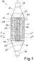
- Figure 1 shows an exchanger as a whole denoted by 10, produced according to principles of the present invention.
- the exchanger 10 comprises a pressurised shell 11, at the opposite ends of which there are conical diffusers or manifolds 12, 13, to which pipes 14, 15 are fitted for the inlet and outlet of the fluid to be cooled (for example, ethylene steam).
- a tube bundle 18 is arranged in the shell between the tubesheets 16 and 17 in order to be immersed in the exchanging fluid (e.g. water) which circulates in the exchanger via inlet and outlet pipes 19 and 20.
- the tubesheets are of the kind known as "thin" and are, therefore, flexible tubesheets, which means that the capacity to withstand flexion due to the internal pressure of the exchanger is ensured by the said tube bundle welded between the tubesheets, and the tubesheets flex outwards also due to the thermal expansion of the bundle.
- the tube bundle advantageously comprises a central zone devoid of tubes and in such area the tubesheets are reciprocally interconnected by tie rods 21.
- the tubes denoted as a whole with 18a and intended to be flowed through by the fluid to be cooled, are arranged around the central zone with the tie rods 21.
- the central zone - devoid of tubes but equipped with tie rods - comprises the centre of the tubesheets.
- the core of the bundle is composed solely of tie rods which do not take part in the circulation of the fluid to be cooled and the tubes are arranged in a torus around the tie rods.
- the area with solely tie rods can be, approximately, in correspondence with the section of the inlet pipe 14.
- the tie rods can be filled with solid metal elements or tubes similar to the tubes in the bundle but sealed at the ends.
- the inertia and section surface area thereof will be comparable to that of the exchanging tubes.
- Figure 2 shows, by way of example, a possible arrangement of the bundle, showing the central tie rods (advantageously arranged in a crosswise fashion) and the tubes surrounding such tie rods.
- the tie rods between the tubesheets help to withstand the pressure thrust between the tubesheets.
- the tie rods can transfer the pressure thrust acting on the said tubesheets from one tubesheet to the other.
- the tie rods are immersed in the cooling fluid just like the tubes but, since such rods are not flowed through by the hot fluid, they have the same temperature as the cooling fluid (for example, in an exchanger for ethylene with exchanging water, such rods can be - for example - approximately 10 °C colder than the exchanging tubes surrounding them).
- the arrangement is therefore advantageous because the buckling of the flexible tubesheets due to the pressure is mitigated in the central part by the different temperature profiles of the tubes and tie rods. Since the stresses are proportional to the deformations, the central part of the flexible tubesheets is less stressed than in the commonly known design solutions.
- the tubes are also less stressed by an axial load, because the further away one moves from the centre, proceeding outwards in a radial fashion, the more the axial stress decreases and the more the flexural stress increases due to the flexion (buckling due to pressure) of the tubesheet.
- the gas distribution in the tubes can be optimised.
- the gas flow is diverted to the tubes surrounding the tie rods and a more uniform distribution of the gas can be obtained in all the exchange tubes, in addition to a minimisation of the formation of vortices and a reduced time of stay in the distribution cone for the flue gas (i.e. better yield from the rapid flue gas cooling reactions).
- the improved distribution of axial forces within the bundle also means that the wall of the most outer peripheral tubes (where the flexural stress component is greater than the axial stress) can be thinner, thereby increasing the internal aperture of the passageway.
- an increased passageway aperture at the periphery of the bundle results in the gas particles - which have to travel freely along a route which is, on average, longer in order to reach the peripheral tubes - having nevertheless the advantage of being exposed to a greater surface area and therefore lower losses of pressure.
- the thicker tubes in the inner part have a greater margin against potential catastrophic ruptures in the event of thinning due to corrosion (even though, with the solution described here, corrosion is either reduced or eliminated).
- an insert 22 can also be featured, arranged in correspondence with the tie rods on the inlet tubesheet 16 on the hot side, in order to reduce the volume in the inlet conical diffuser.
- the insert 22 with a form which is generally tapered in the incoming flow direction, can be easily optimised by means of a computational fluid dynamics system, in order to better match the conformation of the conical diffuser.
- the insert can be made in one piece with the tubesheet or fitted thereonto in various ways, for example by keying.
- a removable fitting can be advantageous in order to be able to replace the insert when, possibly, worn, thereby constituting a sacrificial tubesheet for the protection of the thin tubesheet therebehind.
- diaphragms can also be used in the exchanger according to the invention, arranged transversely along the bundle, to convey the exchanging fluid.
- such diaphragms have the form of discs 23 and rings 24, which alternate along the axis of the bundle in order to ensure circulation as shown by the arrows in Figure 1 , in other words, winding between a peripheral passageway and a central passageway.
- the exchanger in particular a TLE
- the exchanger is, in fact, preferably vertical, with an ascending motion of the fluid (flue gases) to be cooled.
- the first and the last diaphragm have, advantageously, a ring conformation.
- the tie rods are, advantageously, present.
- the central part of the tubesheet is exposed to a speed of approximately zero and therefore there is always a risk, in such central zone, of the accumulation of debris/deposits with consequent overheating locally, since the deposits and fouling in general are an additional thermal resistance which prevents removal of the heat from the tubesheet by the cooling fluid.
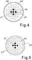
- FIG 4 there is a section of the exchanger shown which shows an advantageous embodiment of one of the ring-shaped diaphragms 24, with the central hole 25 whose perimeter follows the contour of the bundle of tie rods 21 (for example, advantageously arranged in a cross fashion) so that the solid crown part of the baffle is traversed by the exchange tubes and, preferably, supported thereby.
- the baffle may also have a minimum space between the peripheral edge thereof and the inner wall of the exchanger 26.
- the possibility of using ring-shaped diaphragms in proximity to the internal faces of the tubesheets also allows improved inlet and outlet circulation of the cooling fluid.
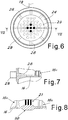
- radial channels 28 can be advantageously featured on the edge of the tubesheet within the exchange chamber.
- the channels 28 are connected to the respective inlet pipes 19 through a connection pipe, for example, in the form of a torus 29 around the periphery of the exchanger.
- such channels are a plurality and are distributed evenly around the circumference of the tubesheet.
- the radial channels 28 face the interior of the exchanger in order to take in the flow of cooling fluid between the tubesheet and the facing ring-shaped baffle.
- the opposite end of the exchange chamber can also feature a similar structure of radial channels 28 for the outlet of exchanging fluid in proximity to the opposite tubesheet 17.
- the solution described above prevents a descending vertical two-phase flow, which would be unstable and/or pulsatile for certain operating points/surface speeds of the liquid and vapour phases.
- the described adduction and extraction arrangement for the exchanging fluid also allows a circular fluid flow symmetry and a configuration known as a 'No Tubes In The Window' configuration, in which all the heat exchange tubes have the same Euler's critical load, regardless of the radial position thereof within the bundle.
- Figure 8 shows a further advantageous embodiment, according to which the tubesheet has a local thickening 30 in the central part, in correspondence with the tie rods 21, which can be used as a corrosion/erosion allowance.
- This thickening is always possible thanks to the fact that, with the structure according to the invention, the central part of the tubesheet is always at approximately the same temperature as the exchanging fluid.
- the thickening can also implement or comprise the external flow diversion insert.
- a tube bundle exchanger with flexible tubesheets produced according to the invention is prone to much fewer erosion and corrosion effects and also allows greater efficiency and flexibility of use. Also, it should be noted that, thanks to the principles of the invention, it is also possible to produce an exchanger which is symmetrical with respect to the transverse plane, i.e., which can be overturned, for example, to extend the working life thereof.
- IBW Internal Bore Welding welds
Landscapes
- Engineering & Computer Science (AREA)
- Physics & Mathematics (AREA)
- Thermal Sciences (AREA)
- Mechanical Engineering (AREA)
- General Engineering & Computer Science (AREA)
- Heat-Exchange Devices With Radiators And Conduit Assemblies (AREA)
- Pressure Welding/Diffusion-Bonding (AREA)
Description
- In the commonly known technique there are many types of heat exchangers for the most disparate uses.
- For example,
DE19639422 describes an air/water heat exchanger for large diesel engines.DE8601340 describes an air dryer, which obviously does not work under pressure, and has solely simple gaskets sealing the ends of the tubes through which the fluid flows. The documentBE436780A claim 1. - The present invention refers instead to a heat exchanger of the type with a pressurised shell and a tube bundle between the inlet and outlet tubesheets. In particular, the exchanger is of the kind with at least one tubesheet, of the 'thin' kind, i.e. with the tubesheet designed to be relatively flexible and to withstand the internal pressure of the exchanger. In still greater detail, the exchanger is a TLE (Transfer Line Exchanger) used in the ethylene production cycle.
- Existing tube bundle exchangers available on the ethylene market are essentially divided into two large categories: those with flexible tubesheets and those with reinforced tubesheets.
- The former promote deflection of the tubesheets as a result of the internal pressure between the tubesheets and thus mitigate secondary stresses acting on the tubes (due to elongation of the tubes as a result of thermal expansion) but they work with higher primary stresses acting on the tubesheet (the strains being proportional to the deformations resulting from elastic reactions) and with tubes working under traction. The latter work with low primary stresses (with tubesheets always remaining flat) but the tubes are physiologically subjected to working in compression, with potential risks of buckling and Euler instability.
- The thin tubesheet exchangers are therefore preferable for some aspects.
- It is true that the TLEs with flexible tubesheets are, however, subject to a potential risk in the event of corrosion of the coupling region between the tubes and tubesheet and/or in correspondence with holes in the diaphragms; in fact the rupture of a tube in the bundle results in the axial thrust from such tube being suddenly spread over the neighbouring tubes, with an increase in the stress acting thereupon and a potential chain reaction consisting of the tubes breaking, with the sudden collapse of the entire exchanger.
- Furthermore, the tube bundle exchangers, especially the TLE kind for ethylene, suffer from a considerable erosion problem caused by the gas in the inlet tubesheet ("hot" tubesheet) as a result of the particulate (coke) being dragged by the high speed gases (>100 m/s).
- Because of the conical diffuser which connects the gas arrival point with the tubesheet and which facilitates the entry in the central part of the bundle and penalises the peripheral tubes, there is also localised erosion primarily in the centre of the tubesheet, where strains can be greater.
- The said potential poor distribution of the hot flue gases in the tubes, due to the conical diffuser facilitating entry in the central part of the bundle and penalising the peripheral tubes, can lead to localised overheating and excessive thermal stresses on the tubesheet and on the tube/tubesheet joints.
- There is, in fact, a possibility of high corrosion on the 'hot' inlet tubesheet on the shell side due to areas of flow which are either dead or stagnant in the lowest points of the natural circulation circuit (thermosyphon) and which are not properly cooled.
- Finally, in the (classic) configuration of a TLE with the ascending vertical flue gas motion, a concentration of vapour bubbles can also be generated in the upper part of the TLE behind the outlet tubesheet ("cold" tubesheet) with potential stagnation/blanketing which triggers overheating and/or high levels of accrued deposition of corrosive substances on the terminal part of the tubes in contract with the tubesheet.
- Fluid dynamic instability can also be generated during the two-phase descending vertical motion which carries the mixture of coolant (generally, water and vapour) to the outlet pipe or pipes, due to the continuous variation of the working point and potential scenarios with low Froude numbers in the liquid phase, which trigger a countercurrent motion between the liquid phase and the vapour phase rather than a cocurrent motion of the two phases in the descending duct.
- To endeavour to improve the situation, various solutions have been proposed within the commonly known technique to endeavour to render water distribution uniform in the lowest point of the circuit (still with reference to a TLE with ascending vertical flue gas motion).
- For example, it has been proposed that a side-to-side flow scrubbing action be performed on the tubesheet by means of a suitably shaped diaphragm appropriately spaced from the tubesheet.
- However, such solution produces a unidirectional high speed, but also stagnation in the direction perpendicular to the flow and in the shaded areas of the tubes.
- In addition, the unidirectional high speed causes a high loss of concentrated load and therefore a decrease in the radiator's recirculation ratio.
- Furthermore, there is an increased possibility of stratification of the corrosive water deposits on the upper face of the diaphragm in correspondence with the through holes for the fluid.
- It has also been proposed that water channelling be provided by means of ducts or tunnels, but such arrangement renders it necessary to ensure that water be drawn upwards in each tunnel in order to wet the surface of the tubes within a rigid tubesheet anchored to the flexible tubesheet. There is, therefore, a reduction in the flow rate at the end of the tunnel, a reduction for which it has been attempted to compensate by shaping the ducts with a section which grows gradually smaller so as to compensate for this effect and maintain high speeds which prevent scaling and deposits. Nevertheless, the high speeds result in a further high loss of concentrated load and therefore a decrease in the radiator's recirculation ratio.
- It has also been proposed that there be water inlets in rings which are concentric to the flue gas tubes, but such arrangement leads to high losses of the inlet load within the ring, because the equivalent diameter of the annular geometry is small. Therefore, there is a greater possibility of clogging due to dragged deposits, resulting in local overheating of the tube wall in correspondence with the inlet. In addition, there are high speeds due to the reduced section of the passageway of the rings, which means a high loss of concentrated load and therefore a decrease in the radiator's recirculation ratio.
-
FR2518730 US2008/038165 is an example of an exchanger for ammonia synthesis with a single thick tubesheet at one end of the bundle and no tubesheet at the other end. -
BE436780 - The main aim of the present invention is to provide an exchanger with a tube bundle and flexible tubesheet which overcomes the drawbacks of the commonly known technique, with a simple and efficient structure and greater operating safety.
- In view of this aim, the decision was made to produce, according to the invention, a heat exchanger with a pressurised shell and a tube bundle with exchanging tubes between flexible tubesheets, characterised by the fact that the flexible tubesheets are reciprocally interconnected by tie rods in a central zone of the tubesheets which is devoid of exchanging tubes and the exchanging tubes in the tube bundle are arranged around such tie rods.
- According to a further aspect of the invention, the heat exchanger is characterised by the fact that transverse diaphragms are arranged along the tube bundle for conveying the exchanging fluid, alternating in shape between discs and rings along the axis of the bundle and, preferably, the diaphragm closest to a tubesheet is ring-shaped. Advantageously, the ring-shaped diaphragms have a central passageway which is crossed solely by tie rods.
- To provide a clearer explanation of the innovative principles of the present invention and the advantages thereof with respect to the commonly known technique, an exemplifying embodiment in which the said principles are applied will be described below, with the help of the accompanying drawings. In the drawings:
-
Figure 1 is a schematic, partially sectioned, side view of an exchanger according to the invention; -
Figure 2 shows a schematic, cross-sectioned view of a first possible arrangement of the tube bundle in the exchanger shown inFigure 1 ; -
Figure 3 shows a schematic, cross-sectioned view of a second possible arrangement of the tube bundle in the exchanger shown inFigure 1 ; -
Figure 4 shows a schematic, cross-sectioned view according to line IV-IV inFigure 1 ; -
Figure 5 shows a schematic, cross-sectioned view according to line V-V inFigure 1 ; -
Figure 6 shows a schematic, cross-sectioned view (according - generally - to line V-V inFigure 1 ) of a possible embodiment of areas, in proximity to the tubesheets, for the inlet and outlet of the coolant within an exchanger according to the invention; -
Figure 7 shows a partial schematic view of a section according to line VII-VII inFigure 6 ; -
Figure 8 shows a schematic, partial, sectioned view of a possible variant of a central zone of the tubesheet in an exchanger according to the invention. - With reference to the figures,
Figure 1 shows an exchanger as a whole denoted by 10, produced according to principles of the present invention. - The
exchanger 10 comprises apressurised shell 11, at the opposite ends of which there are conical diffusers ormanifolds pipes tube bundle 18 is arranged in the shell between thetubesheets outlet pipes - According to the principles of the invention, the tube bundle advantageously comprises a central zone devoid of tubes and in such area the tubesheets are reciprocally interconnected by
tie rods 21. The tubes, denoted as a whole with 18a and intended to be flowed through by the fluid to be cooled, are arranged around the central zone with thetie rods 21. As can be seen in the figures, the central zone - devoid of tubes but equipped with tie rods - comprises the centre of the tubesheets. Essentially, the core of the bundle is composed solely of tie rods which do not take part in the circulation of the fluid to be cooled and the tubes are arranged in a torus around the tie rods. - Advantageously, the area with solely tie rods can be, approximately, in correspondence with the section of the
inlet pipe 14. The tie rods can be filled with solid metal elements or tubes similar to the tubes in the bundle but sealed at the ends. Generally, the inertia and section surface area thereof will be comparable to that of the exchanging tubes. -
Figure 2 shows, by way of example, a possible arrangement of the bundle, showing the central tie rods (advantageously arranged in a crosswise fashion) and the tubes surrounding such tie rods. - The tie rods between the tubesheets help to withstand the pressure thrust between the tubesheets. In other words, the tie rods can transfer the pressure thrust acting on the said tubesheets from one tubesheet to the other.
- The innovative structure of the exchanger which features flexible tubesheets with the presence of tie rods in the central part of the bundle and exchanging tubes solely around the tie rods provides various advantages.
- First and foremost, the tie rods are immersed in the cooling fluid just like the tubes but, since such rods are not flowed through by the hot fluid, they have the same temperature as the cooling fluid (for example, in an exchanger for ethylene with exchanging water, such rods can be - for example - approximately 10 °C colder than the exchanging tubes surrounding them).
- The arrangement is therefore advantageous because the buckling of the flexible tubesheets due to the pressure is mitigated in the central part by the different temperature profiles of the tubes and tie rods. Since the stresses are proportional to the deformations, the central part of the flexible tubesheets is less stressed than in the commonly known design solutions.
- At the same time, the tubes are also less stressed by an axial load, because the further away one moves from the centre, proceeding outwards in a radial fashion, the more the axial stress decreases and the more the flexural stress increases due to the flexion (buckling due to pressure) of the tubesheet.
- Thanks to the decrease in the axial forces on the tubes and the improved diversion of the flow towards the peripheral tubes, the gas distribution in the tubes can be optimised.
- In fact, the gas flow is diverted to the tubes surrounding the tie rods and a more uniform distribution of the gas can be obtained in all the exchange tubes, in addition to a minimisation of the formation of vortices and a reduced time of stay in the distribution cone for the flue gas (i.e. better yield from the rapid flue gas cooling reactions).
- The improved distribution of axial forces within the bundle also means that the wall of the most outer peripheral tubes (where the flexural stress component is greater than the axial stress) can be thinner, thereby increasing the internal aperture of the passageway. Alternatively, it is also possible to increase the diameter of the outer tubes as shown, by way of example, in
Figure 3 . - In any case, an increased passageway aperture at the periphery of the bundle results in the gas particles - which have to travel freely along a route which is, on average, longer in order to reach the peripheral tubes - having nevertheless the advantage of being exposed to a greater surface area and therefore lower losses of pressure.
- Incidentally, the thicker tubes in the inner part have a greater margin against potential catastrophic ruptures in the event of thinning due to corrosion (even though, with the solution described here, corrosion is either reduced or eliminated).
- Returning to
Figure 1 , aninsert 22 can also be featured, arranged in correspondence with the tie rods on theinlet tubesheet 16 on the hot side, in order to reduce the volume in the inlet conical diffuser. - This allows the time of stay of the fluid in the conical diffuser to be reduced and improved protection of the hot tubesheet to be offered. Furthermore, diversion is the fluid towards the inlets of the tubes in the bundle is further improved.
- The
insert 22, with a form which is generally tapered in the incoming flow direction, can be easily optimised by means of a computational fluid dynamics system, in order to better match the conformation of the conical diffuser. The insert can be made in one piece with the tubesheet or fitted thereonto in various ways, for example by keying. A removable fitting can be advantageous in order to be able to replace the insert when, possibly, worn, thereby constituting a sacrificial tubesheet for the protection of the thin tubesheet therebehind. - As can be seen, again in
Figure 1 , diaphragms can also be used in the exchanger according to the invention, arranged transversely along the bundle, to convey the exchanging fluid. - Advantageously, such diaphragms have the form of
discs 23 and rings 24, which alternate along the axis of the bundle in order to ensure circulation as shown by the arrows inFigure 1 , in other words, winding between a peripheral passageway and a central passageway. The exchanger (in particular a TLE) is, in fact, preferably vertical, with an ascending motion of the fluid (flue gases) to be cooled. - As seen in
Figure 1 , the first and the last diaphragm have, advantageously, a ring conformation. This is possible due to the fact that, in the central passageway of the ring-shaped diaphragm, where the flow of cooling fluid passes, solely the tie rods are, advantageously, present. In fact, in general, the central part of the tubesheet is exposed to a speed of approximately zero and therefore there is always a risk, in such central zone, of the accumulation of debris/deposits with consequent overheating locally, since the deposits and fouling in general are an additional thermal resistance which prevents removal of the heat from the tubesheet by the cooling fluid. - If, according to the commonly known technique, there were no exchange tubes in such central zone, the use of ring-shaped diaphragms in proximity to the tubesheets would be impossible because such arrangement would involve an unacceptable increase in the tubesheet temperature due to the deposits, which would not allow correct removal of the heat conveyed into such zone by the exchange tubes.
- With the principles of the present invention, a possible accumulation of deposits in the central zone of the tubesheet does not, however, result in a rise in temperature locally because the central part of the bundle is not fed with hot fluid.
- In
Figure 4 , there is a section of the exchanger shown which shows an advantageous embodiment of one of the ring-shapeddiaphragms 24, with thecentral hole 25 whose perimeter follows the contour of the bundle of tie rods 21 (for example, advantageously arranged in a cross fashion) so that the solid crown part of the baffle is traversed by the exchange tubes and, preferably, supported thereby. The baffle may also have a minimum space between the peripheral edge thereof and the inner wall of theexchanger 26. - In
Figure 5 , however, there is a section of the exchanger shown which shows an advantageous embodiment of one of the disc-shapeddiaphragms 23, with ampleperipheral space 27 for circulation of the exchanging fluid between the two sides of the disc fluid. - Advantageously, the possibility of using ring-shaped diaphragms in proximity to the internal faces of the tubesheets also allows improved inlet and outlet circulation of the cooling fluid.
- As shown in the embodiment in
Figures 6 and 7 ,radial channels 28 can be advantageously featured on the edge of the tubesheet within the exchange chamber. Thechannels 28 are connected to therespective inlet pipes 19 through a connection pipe, for example, in the form of atorus 29 around the periphery of the exchanger. - Advantageously, such channels are a plurality and are distributed evenly around the circumference of the tubesheet.
- The
radial channels 28 face the interior of the exchanger in order to take in the flow of cooling fluid between the tubesheet and the facing ring-shaped baffle. - Advantageously, the opposite end of the exchange chamber can also feature a similar structure of
radial channels 28 for the outlet of exchanging fluid in proximity to theopposite tubesheet 17. - The possibility of having multiple water inlets and at least one exchanging fluid outlet (which, at the outlet, can be a mixture of water plus steam), which is completely radial and allows a more uniform distribution of the fluid and overcomes various problems encountered with the commonly known systems.
- For example, with reference to a standard vertical TLE with ascending hot flue gases, the solution described above prevents a descending vertical two-phase flow, which would be unstable and/or pulsatile for certain operating points/surface speeds of the liquid and vapour phases.
- The described adduction and extraction arrangement for the exchanging fluid also allows a circular fluid flow symmetry and a configuration known as a 'No Tubes In The Window' configuration, in which all the heat exchange tubes have the same Euler's critical load, regardless of the radial position thereof within the bundle.
- Moreover, by placing the outlet pipe of water/steam mixture flush with the upper tubesheet, the 'downflow' area is eliminated. By creating a torus, with multiple access points, which collects the steam coming from all radial directions, pockets of steam are prevented from forming on the top of the exchanger.
-
Figure 8 shows a further advantageous embodiment, according to which the tubesheet has alocal thickening 30 in the central part, in correspondence with thetie rods 21, which can be used as a corrosion/erosion allowance. This thickening is always possible thanks to the fact that, with the structure according to the invention, the central part of the tubesheet is always at approximately the same temperature as the exchanging fluid. The thickening can also implement or comprise the external flow diversion insert. - At this point, it is clear how the intended aims are achieved. A tube bundle exchanger with flexible tubesheets produced according to the invention is prone to much fewer erosion and corrosion effects and also allows greater efficiency and flexibility of use. Also, it should be noted that, thanks to the principles of the invention, it is also possible to produce an exchanger which is symmetrical with respect to the transverse plane, i.e., which can be overturned, for example, to extend the working life thereof.
- Naturally, the description set out above of an embodiment applying the innovative principles of the present invention is given by way of example of such innovative principles and therefore must not be deemed a limitation of the patent right claimed here. For example, the proportions of the various parts of the exchanger may vary with respect to that shown in the drawings in order to adapt to specific requirements, as is easily imaginable by persons skilled in the art. Also the number of tubes, tie rods and any disc or ring-shaped internal diaphragms may vary depending on the embodiment and the specific requirements.
- Finally, there may be various techniques for fastening the tube bundle to the tubesheets, as is easily imaginable by persons skilled in the art. For example it may be advantageous to use Internal Bore Welding welds (IBW), as are known by persons skilled in the art and as shown schematically in
Figure 7 , for the tube on the left.
Claims (12)
- A heat exchanger (10) with a pressurised shell (11) and a tube bundle (18) with exchanging tubes (18a) between flexible tubesheets (16, 17), whereby the flexible tubesheets (16, 17) are reciprocally interconnected by a plurality of tie rods (21) in a central zone of the tubesheets (16, 17) characterized in that said central zone is devoid of exchanging tubes (18a) and the exchanging tubes (18a) in the tube bundle (18) are arranged around such plurality of tie rods (21).
- A heat exchanger according to Claim 1, characterised by the fact that the exchanging tubes (18a) at the periphery of the bundle (18) have a wall thickness which is less than the wall thickness of the other exchanging tubes (18a) in the bundle.
- A heat exchanger according to Claim 1, characterised by the fact that the exchanging tubes (18a) at the periphery of the bundle have a diameter which is greater than that of the other exchanging tubes (18a) in the bundle.
- A heat exchanger according to Claim 1, characterised by the fact that transverse diaphragms are arranged along the tube bundle (18) for conveying the exchanging fluid, alternating in shape between discs (23) and rings (24) along the axis of the bundle.
- A heat exchanger according to Claim 4, characterised by the fact that the diaphragm closest to a tubesheet is ring-shaped.
- A heat exchanger according to Claim 4, characterised by the fact that the ring-shaped diaphragms (24) have a central passageway (25) which is crossed solely by tie rods.
- A heat exchanger according to Claim 1, characterised by the fact that at least the inlet tubesheet (16) has an insert (22) protruding from the hot side of the tubesheet in the central zone, in correspondence with the tie rods.
- A heat exchanger according to Claim 1, characterised by the fact that at least the inlet tubesheet (16) has a greater thickness in the central zone featuring the connection with the tie rods (21) than in the peripheral part of the tubesheet.
- A heat exchanger according to Claim 1, characterised by the fact that, in proximity to at least the inlet tubesheet (16), there are radial channels (28) present for the inlet of exchanging fluid.
- A heat exchanger according to Claim 1, characterised by the fact that, in proximity to at least the outlet tubesheet (17), there are radial channels (28) present for the outlet of exchanging fluid.
- A heat exchanger according to Claims 9 or 10, characterised by the fact that the radial channels (28) are circumferentially evenly spaced.
- A heat exchanger according to Claims 9 or 10, characterised by the fact that the radial channels (28) are surrounded by and connected to a toroidal pipe (29) for the intake and outlet of exchanging fluid.
Priority Applications (1)
| Application Number | Priority Date | Filing Date | Title |
|---|---|---|---|
| PL16726424T PL3286512T3 (en) | 2015-04-24 | 2016-04-21 | Tube-bundle heat exchanger with improved structure |
Applications Claiming Priority (2)
| Application Number | Priority Date | Filing Date | Title |
|---|---|---|---|
| ITUB2015A000270A ITUB20150270A1 (en) | 2015-04-24 | 2015-04-24 | Shell and tube heat exchanger with IBW welds |
| PCT/IB2016/052259 WO2016170487A1 (en) | 2015-04-24 | 2016-04-21 | Tube-bundle heat exchanger with improved structure |
Publications (2)
| Publication Number | Publication Date |
|---|---|
| EP3286512A1 EP3286512A1 (en) | 2018-02-28 |
| EP3286512B1 true EP3286512B1 (en) | 2019-06-05 |
Family
ID=53765393
Family Applications (2)
| Application Number | Title | Priority Date | Filing Date |
|---|---|---|---|
| EP16726424.1A Active EP3286512B1 (en) | 2015-04-24 | 2016-04-21 | Tube-bundle heat exchanger with improved structure |
| EP16726423.3A Active EP3286514B1 (en) | 2015-04-24 | 2016-04-21 | Heat exchanger |
Family Applications After (1)
| Application Number | Title | Priority Date | Filing Date |
|---|---|---|---|
| EP16726423.3A Active EP3286514B1 (en) | 2015-04-24 | 2016-04-21 | Heat exchanger |
Country Status (4)
| Country | Link |
|---|---|
| EP (2) | EP3286512B1 (en) |
| IT (1) | ITUB20150270A1 (en) |
| PL (1) | PL3286512T3 (en) |
| WO (1) | WO2016170486A1 (en) |
Families Citing this family (5)
| Publication number | Priority date | Publication date | Assignee | Title |
|---|---|---|---|---|
| SI3376150T1 (en) | 2017-03-14 | 2019-11-29 | Alfa Laval Olmi S P A | Protection device for a shell-and-tube equipment |
| CN110500905B (en) * | 2019-07-16 | 2024-05-14 | 上海蓝滨石化设备有限责任公司 | Internal pressure plate bundle and heat exchanger formed by same |
| CN111964510A (en) * | 2020-09-16 | 2020-11-20 | 江苏东方瑞吉能源装备有限公司 | Cold hydrogenation waste heat recovery of polycrystalline silicon recycles device |
| CN113787246B (en) * | 2021-10-15 | 2023-06-16 | 中国电建集团山东电力建设第一工程有限公司 | Welding method for anti-abrasion tile of coiled pipe of heating surface and coiled pipe heat exchanger |
| IT202200026172A1 (en) * | 2022-12-21 | 2024-06-21 | Giovanni Manenti | HEAT EXCHANGER WITH FLUIDS IN INVERTED COUNTERFLOW CONFIGURATION AND RELATED OPERATING METHOD |
Family Cites Families (4)
| Publication number | Priority date | Publication date | Assignee | Title |
|---|---|---|---|---|
| US4943001A (en) * | 1987-07-07 | 1990-07-24 | Nooter Corporation | Tube-type vessel having crevice-free joints and method for manufacturing the same |
| ITMI20020118A1 (en) * | 2002-01-24 | 2003-07-24 | Olmi Spa | HEAT EXCHANGER WITH THIN TUBE PLATE WITH PERFECT STRUCTURE |
| CN202675999U (en) * | 2012-06-19 | 2013-01-16 | 中国石油化工股份有限公司 | Structure of heat exchanger |
| CN103528405A (en) * | 2013-10-17 | 2014-01-22 | 陕西盛迈石油有限公司 | Vertical tube shell type rapid cooling heat exchanger |
-
2015
- 2015-04-24 IT ITUB2015A000270A patent/ITUB20150270A1/en unknown
-
2016
- 2016-04-21 EP EP16726424.1A patent/EP3286512B1/en active Active
- 2016-04-21 EP EP16726423.3A patent/EP3286514B1/en active Active
- 2016-04-21 PL PL16726424T patent/PL3286512T3/en unknown
- 2016-04-21 WO PCT/IB2016/052257 patent/WO2016170486A1/en not_active Ceased
Non-Patent Citations (1)
| Title |
|---|
| None * |
Also Published As
| Publication number | Publication date |
|---|---|
| ITUB20150270A1 (en) | 2016-10-24 |
| EP3286512A1 (en) | 2018-02-28 |
| WO2016170486A1 (en) | 2016-10-27 |
| EP3286514B1 (en) | 2019-12-11 |
| EP3286514A1 (en) | 2018-02-28 |
| PL3286512T3 (en) | 2019-10-31 |
Similar Documents
| Publication | Publication Date | Title |
|---|---|---|
| CA2982899C (en) | Tube-bundle heat exchanger having centrally located tie rods surrounded by exchanger tubes | |
| EP3286512A1 (en) | Tube-bundle heat exchanger with improved structure | |
| US4401153A (en) | Heat exchanger incorporating nitriding-resistant material | |
| US4332294A (en) | Gas cooler with multiply deformed lead tubes | |
| KR102406322B1 (en) | Heat exchangers for harsh service conditions | |
| EP1787081B1 (en) | Reduced vibration tube bundle device | |
| CN214892749U (en) | Heat exchanger for flash tower of fractionating tower | |
| EP4390289B1 (en) | Heat exchanger with fluids in inverted counter-current configuration and operating method thereof | |
| EP0390420A1 (en) | Combined heat exchanger system such as for ammonia synthesis reactor effluent | |
| CN110207508A (en) | A kind of heat exchanger | |
| CN210242495U (en) | Heat exchanger | |
| US4852644A (en) | Tubular heat exchanger | |
| CN114894009A (en) | A heat exchanger with dynamic follow-up sealing baffles | |
| US11306972B2 (en) | Shell and tube heat exchangers | |
| JP5762237B2 (en) | Multi-tube heat exchanger | |
| KR101318129B1 (en) | Heat exchange assembly exchanging heat between a first and a second fluid | |
| CN212884913U (en) | Crystallizer copper pipe with efficient cooling | |
| CN110567296A (en) | High-efficiency low-resistance lubricating oil cooler | |
| CN211204991U (en) | Novel baffling rod heat exchanger device | |
| JPS6128584A (en) | Water cooling wall for dual tower type gasification system | |
| US3435890A (en) | Heat exchanger | |
| CN209230361U (en) | Explosion-proof type double tubesheet seals silicon carbide tubular heat exchanger | |
| JPS6337880B2 (en) | ||
| CN106500538B (en) | A kind of double-flow band-tube type heat exchanger | |
| CN216898452U (en) | Natural ventilation formula circulating water dry-type cooling system |
Legal Events
| Date | Code | Title | Description |
|---|---|---|---|
| STAA | Information on the status of an ep patent application or granted ep patent |
Free format text: STATUS: THE INTERNATIONAL PUBLICATION HAS BEEN MADE |
|
| TPAC | Observations filed by third parties |
Free format text: ORIGINAL CODE: EPIDOSNTIPA |
|
| PUAI | Public reference made under article 153(3) epc to a published international application that has entered the european phase |
Free format text: ORIGINAL CODE: 0009012 |
|
| STAA | Information on the status of an ep patent application or granted ep patent |
Free format text: STATUS: REQUEST FOR EXAMINATION WAS MADE |
|
| 17P | Request for examination filed |
Effective date: 20170921 |
|
| AK | Designated contracting states |
Kind code of ref document: A1 Designated state(s): AL AT BE BG CH CY CZ DE DK EE ES FI FR GB GR HR HU IE IS IT LI LT LU LV MC MK MT NL NO PL PT RO RS SE SI SK SM TR |
|
| AX | Request for extension of the european patent |
Extension state: BA ME |
|
| DAV | Request for validation of the european patent (deleted) | ||
| DAX | Request for extension of the european patent (deleted) | ||
| GRAP | Despatch of communication of intention to grant a patent |
Free format text: ORIGINAL CODE: EPIDOSNIGR1 |
|
| STAA | Information on the status of an ep patent application or granted ep patent |
Free format text: STATUS: GRANT OF PATENT IS INTENDED |
|
| INTG | Intention to grant announced |
Effective date: 20181127 |
|
| GRAS | Grant fee paid |
Free format text: ORIGINAL CODE: EPIDOSNIGR3 |
|
| GRAA | (expected) grant |
Free format text: ORIGINAL CODE: 0009210 |
|
| STAA | Information on the status of an ep patent application or granted ep patent |
Free format text: STATUS: THE PATENT HAS BEEN GRANTED |
|
| AK | Designated contracting states |
Kind code of ref document: B1 Designated state(s): AL AT BE BG CH CY CZ DE DK EE ES FI FR GB GR HR HU IE IS IT LI LT LU LV MC MK MT NL NO PL PT RO RS SE SI SK SM TR |
|
| REG | Reference to a national code |
Ref country code: GB Ref legal event code: FG4D |
|
| REG | Reference to a national code |
Ref country code: CH Ref legal event code: EP |
|
| REG | Reference to a national code |
Ref country code: AT Ref legal event code: REF Ref document number: 1140443 Country of ref document: AT Kind code of ref document: T Effective date: 20190615 |
|
| REG | Reference to a national code |
Ref country code: IE Ref legal event code: FG4D |
|
| REG | Reference to a national code |
Ref country code: DE Ref legal event code: R096 Ref document number: 602016014842 Country of ref document: DE |
|
| REG | Reference to a national code |
Ref country code: NL Ref legal event code: MP Effective date: 20190605 |
|
| REG | Reference to a national code |
Ref country code: LT Ref legal event code: MG4D |
|
| PG25 | Lapsed in a contracting state [announced via postgrant information from national office to epo] |
Ref country code: ES Free format text: LAPSE BECAUSE OF FAILURE TO SUBMIT A TRANSLATION OF THE DESCRIPTION OR TO PAY THE FEE WITHIN THE PRESCRIBED TIME-LIMIT Effective date: 20190605 Ref country code: AL Free format text: LAPSE BECAUSE OF FAILURE TO SUBMIT A TRANSLATION OF THE DESCRIPTION OR TO PAY THE FEE WITHIN THE PRESCRIBED TIME-LIMIT Effective date: 20190605 Ref country code: SE Free format text: LAPSE BECAUSE OF FAILURE TO SUBMIT A TRANSLATION OF THE DESCRIPTION OR TO PAY THE FEE WITHIN THE PRESCRIBED TIME-LIMIT Effective date: 20190605 Ref country code: HR Free format text: LAPSE BECAUSE OF FAILURE TO SUBMIT A TRANSLATION OF THE DESCRIPTION OR TO PAY THE FEE WITHIN THE PRESCRIBED TIME-LIMIT Effective date: 20190605 Ref country code: LT Free format text: LAPSE BECAUSE OF FAILURE TO SUBMIT A TRANSLATION OF THE DESCRIPTION OR TO PAY THE FEE WITHIN THE PRESCRIBED TIME-LIMIT Effective date: 20190605 Ref country code: FI Free format text: LAPSE BECAUSE OF FAILURE TO SUBMIT A TRANSLATION OF THE DESCRIPTION OR TO PAY THE FEE WITHIN THE PRESCRIBED TIME-LIMIT Effective date: 20190605 Ref country code: NO Free format text: LAPSE BECAUSE OF FAILURE TO SUBMIT A TRANSLATION OF THE DESCRIPTION OR TO PAY THE FEE WITHIN THE PRESCRIBED TIME-LIMIT Effective date: 20190905 |
|
| PG25 | Lapsed in a contracting state [announced via postgrant information from national office to epo] |
Ref country code: RS Free format text: LAPSE BECAUSE OF FAILURE TO SUBMIT A TRANSLATION OF THE DESCRIPTION OR TO PAY THE FEE WITHIN THE PRESCRIBED TIME-LIMIT Effective date: 20190605 Ref country code: GR Free format text: LAPSE BECAUSE OF FAILURE TO SUBMIT A TRANSLATION OF THE DESCRIPTION OR TO PAY THE FEE WITHIN THE PRESCRIBED TIME-LIMIT Effective date: 20190906 Ref country code: LV Free format text: LAPSE BECAUSE OF FAILURE TO SUBMIT A TRANSLATION OF THE DESCRIPTION OR TO PAY THE FEE WITHIN THE PRESCRIBED TIME-LIMIT Effective date: 20190605 Ref country code: BG Free format text: LAPSE BECAUSE OF FAILURE TO SUBMIT A TRANSLATION OF THE DESCRIPTION OR TO PAY THE FEE WITHIN THE PRESCRIBED TIME-LIMIT Effective date: 20190905 |
|
| REG | Reference to a national code |
Ref country code: AT Ref legal event code: MK05 Ref document number: 1140443 Country of ref document: AT Kind code of ref document: T Effective date: 20190605 |
|
| PG25 | Lapsed in a contracting state [announced via postgrant information from national office to epo] |
Ref country code: NL Free format text: LAPSE BECAUSE OF FAILURE TO SUBMIT A TRANSLATION OF THE DESCRIPTION OR TO PAY THE FEE WITHIN THE PRESCRIBED TIME-LIMIT Effective date: 20190605 Ref country code: PT Free format text: LAPSE BECAUSE OF FAILURE TO SUBMIT A TRANSLATION OF THE DESCRIPTION OR TO PAY THE FEE WITHIN THE PRESCRIBED TIME-LIMIT Effective date: 20191007 Ref country code: SK Free format text: LAPSE BECAUSE OF FAILURE TO SUBMIT A TRANSLATION OF THE DESCRIPTION OR TO PAY THE FEE WITHIN THE PRESCRIBED TIME-LIMIT Effective date: 20190605 Ref country code: RO Free format text: LAPSE BECAUSE OF FAILURE TO SUBMIT A TRANSLATION OF THE DESCRIPTION OR TO PAY THE FEE WITHIN THE PRESCRIBED TIME-LIMIT Effective date: 20190605 Ref country code: CZ Free format text: LAPSE BECAUSE OF FAILURE TO SUBMIT A TRANSLATION OF THE DESCRIPTION OR TO PAY THE FEE WITHIN THE PRESCRIBED TIME-LIMIT Effective date: 20190605 Ref country code: EE Free format text: LAPSE BECAUSE OF FAILURE TO SUBMIT A TRANSLATION OF THE DESCRIPTION OR TO PAY THE FEE WITHIN THE PRESCRIBED TIME-LIMIT Effective date: 20190605 Ref country code: AT Free format text: LAPSE BECAUSE OF FAILURE TO SUBMIT A TRANSLATION OF THE DESCRIPTION OR TO PAY THE FEE WITHIN THE PRESCRIBED TIME-LIMIT Effective date: 20190605 |
|
| PG25 | Lapsed in a contracting state [announced via postgrant information from national office to epo] |
Ref country code: IS Free format text: LAPSE BECAUSE OF FAILURE TO SUBMIT A TRANSLATION OF THE DESCRIPTION OR TO PAY THE FEE WITHIN THE PRESCRIBED TIME-LIMIT Effective date: 20191005 Ref country code: SM Free format text: LAPSE BECAUSE OF FAILURE TO SUBMIT A TRANSLATION OF THE DESCRIPTION OR TO PAY THE FEE WITHIN THE PRESCRIBED TIME-LIMIT Effective date: 20190605 |
|
| REG | Reference to a national code |
Ref country code: DE Ref legal event code: R097 Ref document number: 602016014842 Country of ref document: DE |
|
| PG25 | Lapsed in a contracting state [announced via postgrant information from national office to epo] |
Ref country code: TR Free format text: LAPSE BECAUSE OF FAILURE TO SUBMIT A TRANSLATION OF THE DESCRIPTION OR TO PAY THE FEE WITHIN THE PRESCRIBED TIME-LIMIT Effective date: 20190605 |
|
| PLBE | No opposition filed within time limit |
Free format text: ORIGINAL CODE: 0009261 |
|
| STAA | Information on the status of an ep patent application or granted ep patent |
Free format text: STATUS: NO OPPOSITION FILED WITHIN TIME LIMIT |
|
| PG25 | Lapsed in a contracting state [announced via postgrant information from national office to epo] |
Ref country code: DK Free format text: LAPSE BECAUSE OF FAILURE TO SUBMIT A TRANSLATION OF THE DESCRIPTION OR TO PAY THE FEE WITHIN THE PRESCRIBED TIME-LIMIT Effective date: 20190605 |
|
| 26N | No opposition filed |
Effective date: 20200306 |
|
| PG25 | Lapsed in a contracting state [announced via postgrant information from national office to epo] |
Ref country code: SI Free format text: LAPSE BECAUSE OF FAILURE TO SUBMIT A TRANSLATION OF THE DESCRIPTION OR TO PAY THE FEE WITHIN THE PRESCRIBED TIME-LIMIT Effective date: 20190605 |
|
| PG25 | Lapsed in a contracting state [announced via postgrant information from national office to epo] |
Ref country code: MC Free format text: LAPSE BECAUSE OF FAILURE TO SUBMIT A TRANSLATION OF THE DESCRIPTION OR TO PAY THE FEE WITHIN THE PRESCRIBED TIME-LIMIT Effective date: 20190605 |
|
| REG | Reference to a national code |
Ref country code: CH Ref legal event code: PL |
|
| PG25 | Lapsed in a contracting state [announced via postgrant information from national office to epo] |
Ref country code: CH Free format text: LAPSE BECAUSE OF NON-PAYMENT OF DUE FEES Effective date: 20200430 Ref country code: LU Free format text: LAPSE BECAUSE OF NON-PAYMENT OF DUE FEES Effective date: 20200421 Ref country code: LI Free format text: LAPSE BECAUSE OF NON-PAYMENT OF DUE FEES Effective date: 20200430 |
|
| REG | Reference to a national code |
Ref country code: BE Ref legal event code: MM Effective date: 20200430 |
|
| PG25 | Lapsed in a contracting state [announced via postgrant information from national office to epo] |
Ref country code: BE Free format text: LAPSE BECAUSE OF NON-PAYMENT OF DUE FEES Effective date: 20200430 |
|
| GBPC | Gb: european patent ceased through non-payment of renewal fee |
Effective date: 20200421 |
|
| PG25 | Lapsed in a contracting state [announced via postgrant information from national office to epo] |
Ref country code: GB Free format text: LAPSE BECAUSE OF NON-PAYMENT OF DUE FEES Effective date: 20200421 Ref country code: IE Free format text: LAPSE BECAUSE OF NON-PAYMENT OF DUE FEES Effective date: 20200421 |
|
| PG25 | Lapsed in a contracting state [announced via postgrant information from national office to epo] |
Ref country code: MT Free format text: LAPSE BECAUSE OF FAILURE TO SUBMIT A TRANSLATION OF THE DESCRIPTION OR TO PAY THE FEE WITHIN THE PRESCRIBED TIME-LIMIT Effective date: 20190605 Ref country code: CY Free format text: LAPSE BECAUSE OF FAILURE TO SUBMIT A TRANSLATION OF THE DESCRIPTION OR TO PAY THE FEE WITHIN THE PRESCRIBED TIME-LIMIT Effective date: 20190605 |
|
| PG25 | Lapsed in a contracting state [announced via postgrant information from national office to epo] |
Ref country code: MK Free format text: LAPSE BECAUSE OF FAILURE TO SUBMIT A TRANSLATION OF THE DESCRIPTION OR TO PAY THE FEE WITHIN THE PRESCRIBED TIME-LIMIT Effective date: 20190605 |
|
| PGFP | Annual fee paid to national office [announced via postgrant information from national office to epo] |
Ref country code: DE Payment date: 20250429 Year of fee payment: 10 Ref country code: PL Payment date: 20250402 Year of fee payment: 10 |
|
| PGFP | Annual fee paid to national office [announced via postgrant information from national office to epo] |
Ref country code: IT Payment date: 20250424 Year of fee payment: 10 |
|
| PGFP | Annual fee paid to national office [announced via postgrant information from national office to epo] |
Ref country code: FR Payment date: 20250425 Year of fee payment: 10 |