EP3286050B1 - Steuerventileinrichtung für eine parkbremseinrichtung für kraftfahrzeuge sowie parkbremseinrichtung für kraftfahrzeuge - Google Patents
Steuerventileinrichtung für eine parkbremseinrichtung für kraftfahrzeuge sowie parkbremseinrichtung für kraftfahrzeuge Download PDFInfo
- Publication number
- EP3286050B1 EP3286050B1 EP16717629.6A EP16717629A EP3286050B1 EP 3286050 B1 EP3286050 B1 EP 3286050B1 EP 16717629 A EP16717629 A EP 16717629A EP 3286050 B1 EP3286050 B1 EP 3286050B1
- Authority
- EP
- European Patent Office
- Prior art keywords
- control valve
- piston ring
- valve device
- cylinder space
- valve
- Prior art date
- Legal status (The legal status is an assumption and is not a legal conclusion. Google has not performed a legal analysis and makes no representation as to the accuracy of the status listed.)
- Active
Links
Images



Classifications
-
- B—PERFORMING OPERATIONS; TRANSPORTING
- B60—VEHICLES IN GENERAL
- B60T—VEHICLE BRAKE CONTROL SYSTEMS OR PARTS THEREOF; BRAKE CONTROL SYSTEMS OR PARTS THEREOF, IN GENERAL; ARRANGEMENT OF BRAKING ELEMENTS ON VEHICLES IN GENERAL; PORTABLE DEVICES FOR PREVENTING UNWANTED MOVEMENT OF VEHICLES; VEHICLE MODIFICATIONS TO FACILITATE COOLING OF BRAKES
- B60T13/00—Transmitting braking action from initiating means to ultimate brake actuator with power assistance or drive; Brake systems incorporating such transmitting means, e.g. air-pressure brake systems
- B60T13/10—Transmitting braking action from initiating means to ultimate brake actuator with power assistance or drive; Brake systems incorporating such transmitting means, e.g. air-pressure brake systems with fluid assistance, drive, or release
- B60T13/24—Transmitting braking action from initiating means to ultimate brake actuator with power assistance or drive; Brake systems incorporating such transmitting means, e.g. air-pressure brake systems with fluid assistance, drive, or release the fluid being gaseous
- B60T13/26—Compressed-air systems
- B60T13/261—Compressed-air systems systems with both indirect application and application by springs or weights and released by compressed air
- B60T13/263—Compressed-air systems systems with both indirect application and application by springs or weights and released by compressed air specially adapted for coupling with dependent systems, e.g. tractor-trailer systems
-
- B—PERFORMING OPERATIONS; TRANSPORTING
- B60—VEHICLES IN GENERAL
- B60T—VEHICLE BRAKE CONTROL SYSTEMS OR PARTS THEREOF; BRAKE CONTROL SYSTEMS OR PARTS THEREOF, IN GENERAL; ARRANGEMENT OF BRAKING ELEMENTS ON VEHICLES IN GENERAL; PORTABLE DEVICES FOR PREVENTING UNWANTED MOVEMENT OF VEHICLES; VEHICLE MODIFICATIONS TO FACILITATE COOLING OF BRAKES
- B60T13/00—Transmitting braking action from initiating means to ultimate brake actuator with power assistance or drive; Brake systems incorporating such transmitting means, e.g. air-pressure brake systems
- B60T13/10—Transmitting braking action from initiating means to ultimate brake actuator with power assistance or drive; Brake systems incorporating such transmitting means, e.g. air-pressure brake systems with fluid assistance, drive, or release
- B60T13/24—Transmitting braking action from initiating means to ultimate brake actuator with power assistance or drive; Brake systems incorporating such transmitting means, e.g. air-pressure brake systems with fluid assistance, drive, or release the fluid being gaseous
- B60T13/26—Compressed-air systems
- B60T13/38—Brakes applied by springs or weights and released by compressed air
-
- B—PERFORMING OPERATIONS; TRANSPORTING
- B60—VEHICLES IN GENERAL
- B60T—VEHICLE BRAKE CONTROL SYSTEMS OR PARTS THEREOF; BRAKE CONTROL SYSTEMS OR PARTS THEREOF, IN GENERAL; ARRANGEMENT OF BRAKING ELEMENTS ON VEHICLES IN GENERAL; PORTABLE DEVICES FOR PREVENTING UNWANTED MOVEMENT OF VEHICLES; VEHICLE MODIFICATIONS TO FACILITATE COOLING OF BRAKES
- B60T13/00—Transmitting braking action from initiating means to ultimate brake actuator with power assistance or drive; Brake systems incorporating such transmitting means, e.g. air-pressure brake systems
- B60T13/10—Transmitting braking action from initiating means to ultimate brake actuator with power assistance or drive; Brake systems incorporating such transmitting means, e.g. air-pressure brake systems with fluid assistance, drive, or release
- B60T13/66—Electrical control in fluid-pressure brake systems
- B60T13/68—Electrical control in fluid-pressure brake systems by electrically-controlled valves
- B60T13/683—Electrical control in fluid-pressure brake systems by electrically-controlled valves in pneumatic systems or parts thereof
-
- B—PERFORMING OPERATIONS; TRANSPORTING
- B60—VEHICLES IN GENERAL
- B60T—VEHICLE BRAKE CONTROL SYSTEMS OR PARTS THEREOF; BRAKE CONTROL SYSTEMS OR PARTS THEREOF, IN GENERAL; ARRANGEMENT OF BRAKING ELEMENTS ON VEHICLES IN GENERAL; PORTABLE DEVICES FOR PREVENTING UNWANTED MOVEMENT OF VEHICLES; VEHICLE MODIFICATIONS TO FACILITATE COOLING OF BRAKES
- B60T15/00—Construction arrangement, or operation of valves incorporated in power brake systems and not covered by groups B60T11/00 or B60T13/00
- B60T15/02—Application and release valves
- B60T15/18—Triple or other relay valves which allow step-wise application or release and which are actuated by brake-pipe pressure variation to connect brake cylinders or equivalent to compressed air or vacuum source or atmosphere
- B60T15/20—Triple or other relay valves which allow step-wise application or release and which are actuated by brake-pipe pressure variation to connect brake cylinders or equivalent to compressed air or vacuum source or atmosphere controlled by two fluid pressures
Definitions
- the present invention relates to a control valve device for a parking brake device for motor vehicles, having a housing with a cylinder space and a housing chamber, a switching piston guided in the cylinder space of the housing, a spring, by means of which the switching piston is spring-loaded, with a first connection and a second connection, which connected to the housing chamber, and a third port connected to the cylinder space. Furthermore, the present invention relates to a parking brake device for motor vehicles.
- Parking brakes also called parking brakes
- spring-loaded brake cylinders which, in the released position, apply compressed air to a spring compression chamber and thus keep the spring tensioned, while for parking braking the spring compression chamber is vented, i.e. connected to atmospheric pressure, so that the brake cylinder generates a braking force under the action of the spring (cf. Bosch, Kraftfahrtechnisches Taschenbuch, 22nd edition, Düsseldorf, 1995, p. 648 ).
- control valve device for a parking brake device for motor vehicles of the type mentioned in an advantageous manner, in particular to the effect that a control valve device can be constructed more simply and in particular in connection with the so-called Stretch brake function offers better adjustment options in terms of working behavior and switching point.
- a control valve device for a parking brake device for motor vehicles has a housing with a cylinder chamber and a housing chamber, a switching piston guided in the cylinder chamber of the housing, a spring, by means of which the Switching piston is spring-loaded, has a first port and a second port, which are connected to the housing chamber, and a third port, which is connected to the cylinder chamber, wherein the switching piston has a first piston ring and a second piston ring, the first piston ring in Cylinder chamber is guided and the second piston ring is located outside of the cylinder chamber in a housing chamber, wherein in a first switching position the second piston ring seals the cylinder chamber against the housing chamber and in at least a second switching position the cylinder chamber and the Gepurka are always connected to one another, wherein in the first switching position the pneumatically active surfaces of the first piston ring and of the second piston ring, which face one another,
- the invention is based on the basic idea of influencing the adjustability of the control valve device by designing the dimensions of the two piston rings of the switching piston. Due to the fact that in the first switching position the pneumatically active surfaces of the first piston ring and the second piston ring are essentially identical, the response behavior and the switching point of the control valve device can be adjusted with great precision. In particular, it is possible to set the response behavior of the control valve device by selecting the spring.
- the control valve device can be a pneumatic control valve. In particular, the control valve device can be a 3/2-way valve.
- the cylinder chamber is sealed off from the housing chamber by means of a seal arranged on the second piston ring when the switching piston is in the first switching position.
- the seal can be formed, for example, by an O-ring or by a vulcanized seal. This achieves a simple and secure sealing of the cylinder space and housing chamber. This simple structure also increases the reliability of the control valve device.
- the seal can be located in the annular surface of the second piston ring facing the cylinder chamber. This has the advantage that the seal does not slide against a wall when changing from the first switching position to the second switching position and vice versa, but only rests in the first switching position and is otherwise free. This also improves the service life of the seal and its sealing effect.
- a projection can be provided by increasing the diameter in the housing, on which the seal bears in a sealing manner in the first switching position. This achieves a reliable sealing effect and sealing of the cylinder space and housing chamber in the first switching position.
- the approach can have a peripheral projection.
- it can be provided that in the first switching position of the peripheral projection and the seal come to rest on each other.
- the sealing effect can be improved because the seal is not seated on a flat surface of the attachment, but on a separate structure such as a peripheral projection in the first switching position.
- a projection is provided by means of a diameter enlargement, on which a sealing element is arranged, in particular the sealing element being an O-ring or a vulcanized seal.
- the second piston ring rests sealingly on the sealing element in the second switching position, in particular with the second piston ring having a circumferential projection which rests sealingly on the sealing element.
- a second seal is arranged in the radial surface of the first piston ring, which is placed against the wall of the cylinder chamber. This provides a seal in the area of the first piston ring that is displaceable. Depending on the switching position of the switching piston, the annular space defined by the switching piston and the cylinder space is enlarged or reduced. The second seal is used to seal off the annular space from a part in the housing of the control valve device that is on the side of the piston ring that faces away from the annular space.
- the second seal may be the only seal placed against the wall of the cylinder space. As a result, less friction is generated overall when the switching piston moves. This also increases the adjustment possibilities of the control valve device, because the lower friction during the movement of the switching piston enables a wider range of switching points to be selected. It is also conceivable, for example, to be able to keep the switching piston stable in the first switching position only by applying pressure via the third connection, because the dimensioning of the pneumatically active surfaces of the first piston ring and the second piston ring means that the applied pressure is initially does not affect the switch position.
- the spring can be arranged in a spring chamber which is pneumatically separated from the cylinder chamber by the second seal. This simplifies the construction of the control valve device.
- the spring chamber can have a further connection.
- the switching piston can be actuated pneumatically via the spring chamber.
- the second piston ring closes the first connection in the second switching position. This makes it possible to seal off the first connection from the second connection in the second switching position.
- the present invention relates to a parking brake device for motor vehicles with at least one control valve device.
- the control valve device of this parking brake device is the control valve device described above or one of the possible embodiments for this.
- the figure 1 shows a schematic representation of an embodiment of a parking brake device according to the invention for motor vehicles.
- figure 1 shows a schematic representation of a first exemplary embodiment of a parking brake device 1 according to the invention for motor vehicles.
- the parking brake device 1 has a check valve 10, by means of which the parking brake device 1 is connected to a compressed air supply, not shown in detail.
- a filter unit 12 and a throttle 14 can be provided downstream of the check valve 10 .
- the parking brake device 1 also has a first electrically controllable solenoid valve 16 and a second electrically controllable solenoid valve 18, at the outputs of which a pneumatically controllable control valve 20 is connected as the control valve device 20.
- the two solenoid valves 16 and 18 are connected via the check valve 10 to the compressed air source of the vehicle, not shown, via which compressed air can be supplied.
- Both solenoid valves 16 and 18 are each brought into a rest position by a spring 17 and 19, respectively.
- the solenoid valve 16 is designed as a so-called 2/2-way valve.
- the spring 17 makes the solenoid valve 16 monostable, namely stable in the rest position.
- the solenoid valve 16 it is also conceivable for the solenoid valve 16 to be in the form of a 3/2-way valve. Such a configuration is for example in DE 10 2008 007 877 B3 shown.
- the solenoid valve 18 is a so-called 3/2-way valve. It is also designed as a control and ventilation valve device with an integrated throttle.
- the spring 19 makes the solenoid valve 18 monostable, namely stable in the rest position.
- the solenoid valve 18 can be designed as a simple monostable 2/2-way valve (then without a ventilation function).
- the pneumatically controllable control valve 20 is brought into a rest position by at least one spring 21 .
- the control valve 20 is designed as a 3/2-way valve. However, due to the way it is connected, it is designed to be bistable.
- FIG 1 the rest positions are shown, in which the corresponding valves 16, 18 and 20 are deactivated.
- the parking brake device 1 is in the parking mode.
- the first solenoid valve 16 has an input 16a and an output 16b.
- the second solenoid valve 18 has an input 18a, an output 18b and a vent output 18c.
- the solenoid valve 16 connects the input 16a to the output 16b.
- the second solenoid valve 18 blocks the input 18a and connects the output 18b to the ventilation output 18c. In the activated position, however, the second solenoid valve 18 connects the input 18a to the output 18b, while the ventilation output 18c is shut off.
- the pneumatically controlled control valve 20 also has three connections, namely an input 20a, an output 20b and a further connection 20c.
- the input 20a is connected to the output 16b of the first solenoid valve 16 via a connecting line 22, 22'.
- the output 20b is connected to an input 26a of a select high valve 26 via a connecting line 24, 24', while the connection 20c is connected to the output 18b of the second solenoid valve 18 via a connecting line 28, 28'.
- the pneumatically controllable control valve 20 blocks the inlet 20a and connects the outlet 20b to the connection 20c.
- the control valve 20 is in the activated position, the input 20a is connected to the output 20b and the connection 20c is shut off.
- the pneumatically controllable control valve 20 can be a normal pneumatic valve. It can also be a pneumatically controllable servo valve. Finally, the control valve 20 can also be electrically controllable, ie it can be a bistable electrically controllable solenoid valve.
- a further line 28" branches off from the line 28 and is connected to the input 26b of the select-high valve 26.
- a quick exhaust valve 30, which may be an ESS valve.
- the connecting line 22"' which branches off the line 22, leads to a vent valve 32, which is a 2/2-way valve (solenoid valve) and is connected to its inlet 32a.
- the vent valve 32 also has a vent outlet 32b. In In the position shown, the vent outlet 32b is blocked.
- the vent valve 32 is brought into a rest position by the spring 33.
- the spring 33 makes the solenoid valve 32 monostable, namely stable in the rest position.
- a line 34 connects the select high valve 26 to a control input 36a of a relay valve 36.
- Another control input 36b of the relay valve 36 is connected to a pneumatic line 38' which is a pneumatic control line from the vehicle's brake pedal and which is pressurized by the vehicle's service brake.
- connection 36c of the relay valve 36 is connected to the check valve 10 via a connecting line 38 and is thereby connected to the compressed air supply.
- the output 36d of the relay valve 36 is connected to a supply line 40, 40' to a pneumatic braking device 42 for the motor vehicle or towing vehicle and to a further line 44.
- the pneumatic brake device 42 of the motor vehicle or towing vehicle can have a pressure chamber of a spring-loaded brake cylinder (not shown in detail).
- the spring-loaded brake is released when the pressure chamber of the spring-loaded brake cylinder is pressurized with compressed air.
- the parking brake is activated by the spring of the spring-loaded brake cylinder when said pressure chamber is vented.
- a trailer control module 46 is also arranged downstream of the relay valve 36 in addition to the pneumatic brake device 42 for the motor vehicle or towing vehicle.
- the trailer control module 46 is connected as follows: A line 40" branches off line 40 and is connected to an inlet 48a of a select low valve 48. A second inlet 48b of the select low valve 48 is connected via line 24, 24" to the inlet 20b of the Control valve 20 connected.
- An output 48c of the select low valve 48 is connected to an input 52a of a select high valve 52 via a line 50 .
- Another input 52b of the select-high valve 52 is connected to a line 22'', in which a 3/2-way valve 54 (can be designed like a solenoid valve 18) is arranged.
- the connections 54a, 54b are in the position shown connected with each other.
- the trailer control module 46 is in turn connected to the connection 52c of the select high valve 52 via a line 56 .
- control valve 20 is shown in detail.
- figure 3 shows the control valve device 20, ie the control valve 20, in the position in which the control valve 20 is in the parking mode, see also figure 1 .
- the control valve 20 has a housing 60 with a cylinder space 62 and a housing chamber 64.
- a switching piston 66 is guided in the cylinder space 62 of the housing 60 .
- the switching piston 66 is spring-loaded by means of the spring 21 .
- control valve 20 has the connections 20a, 20b and 20c.
- the first port 20a and the second port 20b are connected to the housing chamber 64 .
- the third port 20c is connected to the cylinder space 62 .
- the switching piston 66 has a first piston ring 68 and a second piston ring 70 .
- the first piston ring 68 is guided in the cylinder space 62 and the second piston ring 70 is located outside of the cylinder space 62 in the housing chamber 64 .
- control valve 20 There are essentially two relevant switching positions for the control valve 20 .
- the cylinder chamber 62 In the first switching position, the cylinder chamber 62 is sealed off from the housing chamber 64 by the second piston ring 70, cf. figure 5 .
- the pneumatically effective surfaces of the first piston ring 68 and of the second piston ring 70 are essentially identical.
- the cylinder chamber 62 and the housing chamber 64 are connected to one another, cf. figure 3 .
- figure 4 shows the transition from the first switch position to the second switch position.
- the cylinder chamber 62 is sealed off from the housing chamber 64 by means of a seal 72 arranged on the second piston ring 70 when the switching piston 66 is in the first switching position.
- the seal 72 is located in the annular surface 74 of the second piston ring 70 facing the cylinder chamber 62.
- a projection 76 is provided by a diameter widening in the housing 60, on which the seal 72 rests sealingly in the first switching position.
- the projection 76 has a peripheral projection 78 .
- a second seal 82 is arranged in the radial surface 80 of the first piston ring 68 and is positioned against the wall 84 of the cylinder chamber 62 .
- the second seal 82 is the only seal 82 that is employed against the wall 84 of the cylinder space 62 .
- the spring 21 is arranged in a spring chamber 86 which is pneumatically separated from the cylinder chamber 62 by the second seal 82 .
- the spring chamber 86 has a further outlet 88 .
- the outlet 88 serves to equalize the pressure and connects the spring chamber 86 to the atmosphere.
- the output 88 is also designed as a further control input. However, this is not mandatory.
- the second piston ring 70 closes the first connection 20a in the second switching position.
- a rubber insert 90 is provided in the second piston ring 70 on the side facing away from the cylinder space 62 .
- the device has two safe, stable states, namely the normal driving state and the parking brake activated state (as in figure 1 shown). If the electrical supply fails, the state immediately preceding the failure is maintained in a stable manner.
- the safety function is implemented by the bistable control valve 20.
- This control valve 20 is in figure 1 Park position shown held by the spring 21.
- the connections 20b and 20c of the control valve 20 are connected and vented via the quick exhaust valve 30 and the second solenoid valve 18 via the inlet 18b to its vent outlet 18c.
- the control valve 20 is deactivated and brought into the position shown by the spring 21 . This is one of the two stable states of the control valve 20.
- control valve 20 With the parking brake deactivated, i.e. in the driving condition as in figure 2 shown, the control valve 20 is switched through, ie activated. The input 20a is then connected to the output 20b.
- the valve 18 can then return to the rest position or it is irrelevant for the driving state which position the valve 18 assumes.
- the pressure coming from the outlet 20b reaches the control inlet 36a of the relay valve 36, which switches through and thus allows the pressure from its inlet 36c to reach the spring chamber of the spring-loaded brake cylinder via the line 40, 40', see above that the service brake of the motor vehicle or towing vehicle is released.
- the control valve 20 is then in the second, pressure held, stable position.
- Switching from the driving state to the parking brake is effected by the first solenoid valve 16 and the second solenoid valve 18, the quick exhaust valve 30 and the vent valve 32. If the first solenoid valve 16 is activated, its input 16a and its output 16b are shut off. In addition, the second solenoid valve 18 is switched in such a way that the input 18a is blocked and the outputs 18b and 18c are connected to one another. Pressure can thus escape via the quick exhaust valve 30 and the exhaust outlet 18c of the solenoid valve 18 . Since the venting valve 32 is also switched in such a way that the inlet 33a and the outlet 32b are connected to one another, so that venting can take place via the venting outlet 32b, the pressure in the lines leading to the control valve 20 drops.
- control valve device 20 is switched in such a way that the relay valve 36 is switched through and the operating pressure is applied to the pneumatic brake 42 via the line 38 and this is thereby opened, ie it is in the driving state.
- At least one control input of the trailer control module 46 is pressurized via the branch line 56 of the trailer control module 46 during the execution of the stretch brake function.
- Solenoid valve 16 is closed and solenoid valves 18 and 32 are open.
- the control valve 20 is also open, i.e. the ports 20a and 20b are connected to one another.
- the operating pressure is present at the control input 36a of the relay valve 36 via the line 28" so that this switches through and the pneumatic brake device 42 is supplied with compressed air via the line 38 and is therefore open.
- Compressed air is therefore also present via the line 28" at the outlet 20c.
- control valve device 20 holds the position required for the driving position and does not switch over.
- Pressure is also present in line 24 .
- the pressure present in line 24 is therefore also present in branch line 56 of trailer control module 46 .
- the compressed air supplied via the supply line 22" is set to a certain pressure by means of the exhaust air valve 54. Since a higher operating pressure is present at the select-high valve 26 via the input 26b, this has priority in the select -High valve 26.
- the select-low valve 48 is switched through and the compressed air in the line 24, 24" reaches the trailer control module 46, so that this is activated and the brake of the trailer brakes.
Landscapes
- Engineering & Computer Science (AREA)
- Transportation (AREA)
- Mechanical Engineering (AREA)
- Physics & Mathematics (AREA)
- Fluid Mechanics (AREA)
- Braking Systems And Boosters (AREA)
- Valves And Accessory Devices For Braking Systems (AREA)
Description
- Die vorliegende Erfindung betrifft eine Steuerventileinrichtung für eine Parkbremseinrichtung für Kraftfahrzeuge mit einem Gehäuse mit einem Zylinderraum und einer Gehäusekammer, einem im Zylinderraum des Gehäuses geführten Schaltkolben, einer Feder, mittels derer der Schaltkolben federbelastet ist, mit einem ersten Anschluss und einem zweiten Anschluss, die mit der Gehäusekammer verbunden sind, und einem dritten Anschluss, der mit dem Zylinderraum verbunden ist. Des Weiteren betrifft die vorliegende Erfindung eine Parkbremseinrichtung für Kraftfahrzeuge.
- Parkbremsen (auch Feststellbremsen genannt) von Nutzfahrzeugen einschließlich Anhängern sowie Schienenfahrzeugen sind heute regelmäßig mit Federspeicherbremszylindern ausgestattet, die in Lösestellung einen Federkompressionsraum mit Druckluft beaufschlagen und dadurch die Feder gespannt halten, während zum Parkbremsen der Federkompressionsraum entlüftet, d. h. mit Atmosphärendruck verbunden wird, so dass der Bremszylinder unter Wirkung der Feder eine Bremskraft erzeugt (vgl. Bosch, Kraftfahrtechnisches Taschenbuch, 22. Auflage, Düsseldorf, 1995, S. 648).
- Aus der
DE 10 2009 059 816 A1 ist bereits eine gattungsgemäße Parkbremseinrichtung für Kraftfahrzeuge bekannt, die eine bi-stabile Steuerventileinrichtung aufweist. - Aus der
WO 2014/009457 A1 ist eine gattungsgemäße Steuerventileinrichtung für eine Parkbremseinrichtung für Kraftfahrzeuge bekannt. - Es ist die Aufgabe der vorliegenden Erfindung, eine Steuerventileinrichtung für eine Parkbremseinrichtung für Kraftfahrzeuge der eingangs genannten Art in vorteilhafter Weise weiter zu bilden, insbesondere dahingehend, dass eine Steuerventileinrichtung einfacher aufgebaut sein kann und insbesondere im Zusammenhang mit der sog. Stretch-Brake-Funktion bessere Einstellmöglichkeiten hinsichtlich Arbeitsverhalten und Schaltpunkt bietet.
- Diese Aufgabe wird erfindungsgemäß gelöst durch eine Parkbremseinrichtung mit den Merkmalen des Anspruchs 1. Danach ist vorgesehen, dass eine Steuerventileinrichtung für eine Parkbremseinrichtung für Kraftfahrzeuge ein Gehäuse mit einem Zylinderraum und einer Gehäusekammer, einen im Zylinderraum des Gehäuses geführten Schaltkolben, eine Feder, mittels derer der Schaltkolben federbelastet ist, einen ersten Anschluss und einen zweiten Anschluss, die mit der Gehäusekammer verbunden sind, und einen dritten Anschluss, der mit dem Zylinderraum verbunden ist, aufweist, wobei der Schaltkolben einen ersten Kolbenring und einen zweiten Kolbenring aufweist, wobei der erste Kolbenring im Zylinderraum geführt ist und wobei der zweite Kolbenring außerhalb des Zylinderraums in einer Gehäusekammer befindlich ist, wobei in einer ersten Schaltstellung der zweite Kolbenring den Zylinderraum gegen die Gehäusekammer abdichtet und in wenigstens einer zweiten Schaltstellung der Zylinderraum und die Gehäusekammer miteinander verbunden sind, wobei in der ersten Schaltstellung die pneumatisch wirksamen Flächen des ersten Kolbenrings und des zweiten Kolbenrings, die einander zugewandt sind, im Wesentlichen identisch sind.
- Die Erfindung basiert auf dem Grundgedanken, durch die Gestaltung der Abmessungen der beiden Kolbenringe des Schaltkolbens die Einstellbarkeit der Steuerventileinrichtung zu beeinflussen. Durch den Umstand, dass in der ersten Schaltstellung die pneumatisch wirksamen Flächen des ersten Kolbenrings und des zweiten Kolbenrings im Wesentlichen identisch sind, lässt sich das Ansprechverhalten und der Schaltpunkt der Steuerventileinrichtung hochgenau einstellen. Insbesondere ist es möglich, durch die Wahl der Feder das Ansprechverhalten der Steuerventileinrichtung einzustellen. Die Steuerventileinrichtung kann ein pneumatisches Steuerventil sein. Insbesondere kann die Steuerventileinrichtung ein 3/2-Wegeventil sein.
- Aufgrund des Umstandes, dass in der ersten Schaltstellung die pneumatisch wirksame Flächen des ersten Kolbenrings und des zweiten Kolbenrings der Steuerventileinrichtung im Wesentlichen identisch sind, wird es möglich, sämtliche Eingänge bzw. Ausgänge der Steuerventileinrichtung mit Druckluft zu versorgen und dabei nicht die pneumatische Bremsvorrichtung, die die erfindungsgemäße Steuerventileinrichtung aufweist, zu beeinträchtigen, also insbesondere die Parkbremseinrichtung aus der Fahrstellung in die Parkbremsstellung umzuschalten bzw. in die Nähe des Schaltpunktes zu gelangen. Dies ist insbesondere im Zusammenhang mit der sog. Stretch-Brake-Funktion (nur der Anhänger wird gebremst) von Vorteil. Es wird also möglich, während des Fahrzustandes der Parkbremseinrichtung unabhängig von der gelösten Parkbremse das Anhängersteuermodul der Parkbremseinrichtung anzusteuern und zu aktivieren, und dies aufgrund der Ausgestaltung der erfindungsgemäßen Steuerventileinrichtung derart, dass trotz entsprechendem Anliegen von Druck an sämtlichen Eingängen der Steuerventileinrichtung es nicht zu einem Umschalten aus der Fahrstellung in die Parkbremsstellung kommt und man insbesondere auch nicht in die Nähe des Schaltpunktes gelangt.
- In weiterer Ausgestaltung der Erfindung kann vorgesehen sein, dass der Zylinderraum gegen die Gehäusekammer mittels einer am zweiten Kolbenring angeordneten Dichtung abgedichtet ist, wenn sich der Schaltkolben in der ersten Schaltstellung befindet. Die Dichtung kann beispielsweise durch einen O-Ring oder durch eine aufvulkanisierte Dichtung ausgebildet sein. Dadurch wird eine einfache und sichere Abdichtung von Zylinderraum und Gehäusekammer erreicht. Durch diesen einfachen Aufbau wird zudem die Zuverlässigkeit der Steuerventileinrichtung erhöht.
- Die Dichtung kann sich in der dem Zylinderraum zugewandten Ringfläche des zweiten Kolbenrings befinden. Dadurch ergibt sich der Vorteil, dass die Dichtung nicht beim Wechseln von der ersten Schaltstellung in die zweite Schaltstellung und umgekehrt an einer Wandung gleitend reibt, sondern nur in der ersten Schaltstellung anliegt und im Übrigen frei ist. Dadurch wird auch die Lebensdauer der Dichtung und ihre Dichtwirkung verbessert.
- Am Übergang von Zylinderraum zur Gehäusekammer kann durch eine Durchmesserverbreiterung im Gehäuse ein Ansatz vorgesehen sein, auf dem die Dichtung in der ersten Schaltstellung dichtend anliegt. Dadurch wird eine zuverlässige Dichtwirkung und Abdichtung von Zylinderraum und Gehäusekammer in der ersten Schaltstellung erreicht.
- Der Ansatz kann einen umlaufenden Vorsprung aufweisen. Insbesondere kann vorgesehen sein, dass in der ersten Schaltstellung der umlaufende Vorsprung und die Dichtung aufeinander zu liegen kommen. Dadurch, dass die Dichtung nicht auf einer planen Fläche des Ansatzes, sondern auf einer abgesetzten Struktur wie einem umlaufenden Vorsprung in der ersten Schaltstellung aufsitzt, kann die Dichtwirkung verbessert werden.
- Am Übergang vom Zylinderraum zur Gehäusekammer ist ein Ansatz durch eine Durchmesserverbreiterung vorgesehen, an dem ein Dichtelement angeordnet ist, insbesondere wobei das Dichtelement ein O-Ring oder eine aufvulkanisierte Dichtung ist.
- Der zweite Kolbenring liegt dichtend auf dem Dichtelement in der zweiten Schaltstellung an, insbesondere wobei der zweite Kolbenring einen umlaufenden Vorsprung aufweist, der dichtend auf dem Dichtelement anliegt.
- Des Weiteren kann vorgesehen sein, dass in der Radialfläche des ersten Kolbenrings eine zweite Dichtung angeordnet ist, die gegen die Wandung des Zylinderraums angestellt ist. Dadurch wird im Bereich des ersten Kolbenrings eine Abdichtung bereitgestellt, die verschieblich ist. Je nach Schaltstellung des Schaltkolbens wird somit der durch den Schaltkolben und den Zylinderraum definierte Ringraum vergrößert oder verkleinert. Die zweite Dichtung dient zur Abdichtung des Ringraums gegenüber einem auf der dem Ringraum abgewandten Seite des Kolbenrings liegenden Teils im Gehäuse der Steuerventileinrichtung.
- Die zweite Dichtung kann die einzige Dichtung sein, die gegen die Wandung des Zylinderraums angestellt ist. Dadurch wird insgesamt weniger Reibung bei der Bewegung des Schaltkolbens erzeugt. Dadurch werden auch die Einstellmöglichkeiten der Steuerventileinrichtung erhöht, weil die geringere Reibung bei der Bewegung des Schaltkolbens eine höhere Bandbreite der Auswahl von Schaltpunkten ermöglicht. Auch ist es denkbar, beispielsweise nur durch ein Anlegen von Druck über den dritten Anschluss den Schaltkolben noch stabil in der ersten Schaltstellung halten zu können, weil durch die Bemessung der pneumatisch wirksamen Flächen des ersten Kolbenrings und des zweiten Kolbenrings der anliegende Druck für sich genommen zunächst nicht die Schaltstellung beeinflusst.
- Die Feder kann in einem Federraum angeordnet sein, der durch die zweite Dichtung vom Zylinderraum pneumatisch getrennt ist. Dadurch wird der Aufbau der Steuerventileinrichtung vereinfacht.
- Der Federraum kann einen weiteren Anschluss aufweisen. Dadurch kann über den Federraum der Schaltkolben pneumatisch angesteuert werden.
- Des Weiteren kann vorgesehen sein, dass der zweite Kolbenring in der zweiten Schaltstellung den ersten Anschluss verschließt. Dadurch wird es möglich, den ersten Anschluss gegen den zweiten Anschluss in der zweiten Schaltstellung abzudichten.
- Darüber hinaus betrifft die vorliegende Erfindung eine Parkbremseinrichtung für Kraftfahrzeuge mit wenigstens einer Steuerventileinrichtung. Bei der Steuerventileinrichtung dieser Parkbremseinrichtung handelt es sich um die vorstehend beschriebene Steuerventileinrichtung bzw. eine der möglichen Ausführungsformen hierzu.
- Weitere Einzelheiten und Vorteile der vorliegenden Erfindung sollen nun anhand von in den Zeichnungen dargestellten Ausführungsbeispielen näher erläutert werden.
- Es zeigen:
- Figur 1:
- eine schematische Darstellung eines ersten Ausführungsbeispiels für eine erfindungsgemäße Parkbremseinrichtung mit einem Ausführungsbeispiel einer erfindungsgemäßen Steuerventileinrichtung in der Parkstellung;
- Figur 2:
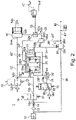
- eine schematische Darstellung der in
Figur 1 gezeigten Parkbremseinrichtung mit einem Ausführungsbeispiel einer erfindungsgemäßen Steuerventileinrichtung in der Fahrstellung; - Figur 3:
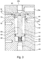
- eine schematische Darstellung des in
Figur 1 undFigur 2 gezeigten Ausführungsbeispiels der Steuerventileinrichtung in einer ersten Schaltstellung; - Figur 4:
- eine schematische Darstellung des in
Figur 1 undFigur 2 gezeigten Ausführungsbeispiels der Steuerventileinrichtung in einer zweiten Schaltstellung; und - Figur 5:
- eine schematische Darstellung des in
Figur 1 undFigur 2 gezeigten Ausführungsbeispiels der Steuerventileinrichtung in einer dritten Schaltstellung. - Die
Figur 1 zeigt eine schematische Darstellung eines Ausführungsbeispiels einer erfindungsgemäßen Parkbremseinrichtung für Kraftfahrzeuge. -
Figur 1 zeigt eine schematische Darstellung eines ersten Ausführungsbeispiels einer erfindungsgemäßen Parkbremseinrichtung 1 für Kraftfahrzeuge. - Die Parkbremseinrichtung 1 weist ein Rückschlagventil 10 auf, mittels dessen die Parkbremseinrichtung 1 an einer nicht näher dargestellten Druckluftversorgung angeschlossen ist.
- Stromabwärts des Rückschlagventils 10 können eine Filtereinheit 12 und eine Drossel 14 vorgesehen sein.
- Die Parkbremseinrichtung 1 hat weiter ein erstes elektrisch steuerbares Magnetventil 16 und ein zweites elektrisch steuerbares Magnetventil 18, an deren Ausgängen als Steuerventileinrichtung 20 ein pneumatisch steuerbares Steuerventil 20 angeschlossen ist.
- Die beiden Magnetventile 16 und 18 sind über das Rückschlagventil 10 mit der nicht dargestellten Druckluftquelle des Fahrzeugs verbunden, über die Druckluft zuführbar ist.
- Beide Magnetventile 16 und 18 werden jeweils durch eine Feder 17 bzw. 19 in eine Ruhelage gebracht.
- Das Magnetventil 16 ist als sogenanntes 2/2-Wegeventil ausgebildet. Durch die Feder 17 ist das Magnetventil 16 monostabil und zwar stabil in der Ruhelage.
- Grundsätzlich ist aber auch denkbar, dass das Magnetventil 16 als 3/2-Wegeventil ausgebildet ist. Eine derartige Konfiguration ist beispielsweise in der
DE 10 2008 007 877 B3 gezeigt. - Das Magnetventil 18 ist ein sogenanntes 3/2-Wegeventil. Es ist zugleich als Steuer- und Entlüftungsventileinrichtung mit integrierter Drossel ausgebildet. Durch die Feder 19 ist das Magnetventil 18 monostabil und zwar stabil in der Ruhelage.
- Denkbar ist auch, dass das Magnetventil 18 als einfaches monostabiles 2/2-Wegeventil ausgebildet sein kann (dann ohne Entlüftungsfunktion).
- Ebenso wird das pneumatisch steuerbare Steuerventil 20 durch wenigstens eine Feder 21 in eine Ruhelage gebracht.
- Das Steuerventil 20 ist als ein 3/2-Wegeventil ausgeführt. Es ist jedoch durch die Art seiner Verschaltung bistabil ausgelegt.
- In
Figur 1 sind jeweils die Ruhelagen dargestellt, bei denen die entsprechenden Ventile 16, 18 bzw. 20 deaktiviert sind. - Die Parkbremseinrichtung 1 befindet sich dabei im Parkmodus.
- Das erste Magnetventil 16 hat einen Eingang 16a und einen Ausgang 16b.
- In ähnlicher Weise hat das zweite Magnetventil 18 einen Eingang 18a, einen Ausgang 18b und einen Entlüftungsausgang 18c.
- In der dargestellten Ruhelage verbindet das Magnetventil 16 den Eingang 16a mit dem Ausgang 16b.
- Das zweite Magnetventil 18 sperrt in der dargestellten Ruhestellung den Eingang 18a ab und verbindet den Ausgang 18b mit dem Entlüftungsausgang 18c. In der aktivierten Position verbindet das zweite Magnetventil 18 dagegen den Eingang 18a mit dem Ausgang 18b, während der Entlüftungsausgang 18c abgesperrt ist.
- Das pneumatisch gesteuerte Steuerventil 20 hat ebenfalls drei Anschlüsse und zwar einen Eingang 20a, einen Ausgang 20b und einen weiteren Anschluss 20c. Der Eingang 20a ist über eine Verbindungsleitung 22, 22' mit dem Ausgang 16b des ersten Magnetventils 16 verbunden. Der Ausgang 20b ist über eine Verbindungsleitung 24, 24' mit einem Eingang 26a eines Select-High-Ventils 26 verbunden, während der Anschluss 20c über eine Verbindungsleitung 28, 28' mit dem Ausgang 18b des zweiten Magnetventils 18 verbunden ist.
- Das pneumatisch steuerbare Steuerventil 20 sperrt in der abgebildeten Ruhestellung den Eingang 20a ab und verbindet den Ausgang 20b mit dem Anschluss 20c. In der aktivierten Stellung des Steuerventils 20 ist dagegen der Eingang 20a mit dem Ausgang 20b verbunden und der Anschluss 20c ist abgesperrt.
- Das pneumatisch steuerbare Steuerventil 20 kann ein normales Pneumatikventil sein. Es kann auch ein pneumatisch steuerbares Servo-Ventil sein. Schließlich kann das Steuerventil 20 auch elektrisch steuerbar sein, d. h. es kann ein bistabiles elektrisch steuerbares Magnetventil sein.
- Von der Leitung 28 zweigt eine weitere Leitung 28" ab, die mit dem Eingang 26b des Select-High-Ventils 26 verbunden ist.
- In der Leitung 28 ist ferner ein Schnellentlüftungsventil 30 vorgesehen, das ein ESS-Ventil sein kann.
- Die Verbindungsleitung 22"', die von der Leitung 22 abzweigt, führt zu einem Entlüftungsventil 32, das ein 2/2-Wegeventil (Magnetventil) ist, und ist mit dessen Eingang 32a verbunden. Das Entlüftungsventil 32 weist weiter einen Entlüftungsausgang 32b auf. In der dargestellten Stellung ist der Entlüftungsausgang 32b gesperrt. Das Entlüftungsventil 32 wird über die Feder 33 in eine Ruhelage gebracht. Durch die Feder 33 ist das Magnetventil 32 monostabil und zwar stabil in der Ruhelage.
- Vom Ausgang 26c des Select-High-Ventils 26 verbindet eine Leitung 34 das Select-High-Ventil 26 mit einem Steuereingang 36a eines Relaisventils 36.
- Ein weiterer Steuereingang 36b des Relaisventils 36 ist mit einer pneumatischen Leitung 38' verbunden, die eine pneumatische Steuerleitung vom Bremspedal des Fahrzeugs ist und die mit Druck der Betriebsbremse des Fahrzeugs beaufschlagt ist.
- Der Anschluss 36c des Relaisventils 36 ist über eine Verbindungsleitung 38 mit dem Rückschlagventil 10 verbunden und hierüber an die Druckluftversorgung angeschlossen.
- Der Ausgang 36d des Relaisventils 36 ist mit einer Zuleitung 40, 40' mit einer pneumatischen Bremsvorrichtung 42 für das Kraftfahrzeug bzw. Zugfahrzeug und mit einer weiteren Leitung 44 verbunden.
- Die pneumatische Bremsvorrichtung 42 des Kraftfahrzeugs bzw. Zugfahrzeugs kann eine Druckkammer eines Federspeicher-Bremszylinders (nicht näher dargestellt) aufweisen. Die Federspeicherbremse ist dann gelöst, wenn die genannte Druckkammer des Federspeicher-Bremszylinders mit Druckluft beaufschlagt ist. Umgekehrt ist die Parkbremse durch die Feder des Federspeicher-Bremszylinders aktiviert, wenn die genannte Druckkammer entlüftet ist.
- Stromabwärts des Relaisventils 36 ist neben der pneumatischen Bremsvorrichtung 42 für das Kraftfahrzeug bzw. Zugfahrzeug auch ein Anhängersteuermodul 46 angeordnet.
- Das Anhängersteuermodul 46 ist dabei wie folgt angeschlossen:
Von der Leitung 40 zweigt eine Leitung 40" ab, die mit einem Eingang 48a eines Select-Low-Ventils 48 verbunden ist. Ein zweiter Eingang 48b des Select-Low-Ventils 48 ist über die Leitung 24, 24" mit dem Eingang 20b des Steuerventils 20 verbunden. - Ein Ausgang 48c des Select-Low-Ventils 48 ist über eine Leitung 50 mit einem Eingang 52a eines Select-High-Ventils 52 verbunden.
- Ein weiterer Eingang 52b des Select-High-Ventils 52 ist mit einer Leitung 22" verbunden, in der sich ein 3/2-Wegeventil 54 (kann wie Magnetventil 18 ausgeführt sein) angeordnet ist. In der gezeigten Stellung sind die Anschlüsse 54a, 54b miteinander verbunden.
- Über den Anschluss 54c kann entlüftet werden.
- Das Anhängersteuermodul 46 ist wiederum über eine Leitung 56 am Anschluss 52c des Select-High-Ventils 52 angeschlossen.
- In den
Figuren 3 bis 5 ist das Steuerventil 20 im Detail gezeigt. -
Figur 3 zeigt dabei die Steuerventileinrichtung 20, also das Steuerventil 20, in der Stellung, in der sich das Steuerventil 20 im Parkmodus befindet, siehe auchFigur 1 . - Das Steuerventil 20 hat ein Gehäuse 60 mit einem Zylinderraum 62 und einer Gehäusekammer 64.
- Im Zylinderraum 62 des Gehäuses 60 ist ein Schaltkolben 66 geführt. Mittels der Feder 21 ist der Schaltkolben 66 federbelastet.
- Wie bereits vorstehend beschrieben weist das Steuerventil 20 die Anschlüsse 20a, 20b und 20c auf. Der erste Anschluss 20a und der zweite Anschluss 20b sind mit der Gehäusekammer 64 verbunden. Der dritte Anschluss 20c ist mit dem Zylinderraum 62 verbunden.
- Der Schaltkolben 66 weist einen ersten Kolbenring 68 und einen zweiten Kolbenring 70 auf. Der erste Kolbenring 68 ist im Zylinderraum 62 geführt und der zweite Kolbenring 70 ist außerhalb des Zylinderraums 62 in der Gehäusekammer 64 befindlich.
- Im Wesentlichen sind zwei relevante Schaltstellungen für das Steuerventil 20 vorhanden.
- In der ersten Schaltstellung ist durch den zweiten Kolbenring 70 der Zylinderraum 62 gegen die Gehäusekammer 64 abgedichtet, vgl.
Figur 5 . In dieser ersten Schaltstellung sind die pneumatisch wirksamen Flächen des ersten Kolbenrings 68 und des zweiten Kolbenrings 70 im Wesentlichen identisch. - In der zweiten Schaltstellung sind der Zylinderraum 62 und die Gehäusekammer 64 miteinander verbunden, vgl.
Figur 3 . -
Figur 4 zeigt den Übergang von der ersten Schaltstellung in die zweite Schaltstellung. - Der Zylinderraum 62 ist gegen die Gehäusekammer 64 mittels einer am zweiten Kolbenring 70 angeordneten Dichtung 72 abgedichtet, wenn sich der Schaltkolben 66 in der ersten Schaltstellung befindet.
- Die Dichtung 72 befindet sich dabei in der dem Zylinderraum 62 zugewandten Ringfläche 74 des zweiten Kolbenrings 70.
- Am Übergang vom Zylinderraum 62 zur Gehäusekammer 64 ist durch eine Durchmesserverbreiterung im Gehäuse 60 ein Ansatz 76 vorgesehen, auf dem die Dichtung 72 in der ersten Schaltstellung dichtend anliegt.
- Der Ansatz 76 weist einen umlaufenden Vorsprung 78 auf.
- Außerdem ist in der Radialfläche 80 des ersten Kolbenrings 68 eine zweite Dichtung 82 angeordnet, die gegen die Wandung 84 des Zylinderraums 62 angestellt ist.
- Die zweite Dichtung 82 ist die einzige Dichtung 82, die gegen die Wandung 84 des Zylinderraumes 62 angestellt ist.
- Die Feder 21 ist in einem Federraum 86 angeordnet, der durch die zweite Dichtung 82 vom Zylinderraum 62 pneumatisch getrennt ist.
- Der Federraum 86 weist einen weiteren Ausgang 88 auf. Der Ausgang 88 dient zum Druckausgleich und verbindet den Federraum 86 mit der Atmosphäre. Grundsätzlich kann vorgesehen sein, dass der Ausgang 88 auch als ein weiterer Steuereingang ausgebildet ist. Dies ist jedoch nicht zwingend erforderlich.
- Wie in
Figur 5 gezeigt, verschließt der zweite Kolbenring 70 in der zweiten Schaltstellung den ersten Anschluss 20a. Hierzu ist im zweiten Kolbenring 70 auf der vom Zylinderraum 62 abgewandten Seite ein Gummieinsatz 90 vorgesehen. - Im Folgenden wird die Wirkungsweise der Parkbremseinrichtung 1 gemäß
Figur 1 undFigur 2 erläutert. - Die Einrichtung hat zwei sichere, stabile Zustände, nämlich den normalen Fahrzustand und den Zustand der aktivierten Parkbremse (wie in
Figur 1 gezeigt). Bei Ausfall der elektrischen Versorgung wird der unmittelbar dem Ausfall vorhergehende Zustand stabil beibehalten. - Die Sicherheitsfunktion wird durch das bistabile Steuerventil 20 realisiert. Dieses Steuerventil 20 wird in der in
Figur 1 dargestellten Parkstellung durch die Feder 21 gehalten. Die Anschlüsse 20b und 20c des Steuerventils 20 sind verbunden und über das Schnellentlüftungsventil 30 und das zweite Magnetventil 18 über den Eingang 18b zu dessen Entlüftungsausgang 18c hin entlüftet. - Das Steuerventil 20 ist deaktiviert und durch die Feder 21 in die dargestellte Stellung gebracht. Dies ist einer der zwei stabilen Zustände des Steuerventils 20.
- In der Parkposition ist auf der Leitung 38 normalerweise kein Druck (Betriebsbremse deaktiviert), so dass an die pneumatischen Steuereingänge 36a und 36b des Relaisventils 36 Atmosphärendruck gelangt. Dieses ist damit entlüftet, so dass auch die Federkammer des Federspeicher-Bremszylinders der pneumatischen Bremsvorrichtung 42 entlüftet ist und damit die Parkbremse angelegt bzw. aktiviert ist.
- Bei deaktivierter Parkbremse, d. h. im Fahrzustand wie in
Figur 2 gezeigt, ist das Steuerventil 20 durchgeschaltet, d. h. aktiviert. Der Eingang 20a ist dann mit dem Ausgang 20b verbunden. - Über das aktivierte Steuerventil 20 gelangt Druck von der Druckmittelquelle über das Rückschlagventil 10 auch zum Steuereingang 36a des Relaisventils 36, welches durchschaltet und damit die Federkammer des Federspeicher-Bremszylinders der Betriebsbremse des Kraftfahrzeugs bzw. Zugfahrzeugs über die Leitung 40, 40' mit Druck beaufschlagt und damit die Betriebsbremse löst. Somit ist die Sicherheitsfunktion realisiert, d. h. beide beschriebenen Betriebszustände sind jeweils für sich stabil, unabhängig von dem Zustand der Stromversorgung der Magnetventile 16 und 18.
- Durch Betätigen des zweiten Magnetventils 18 wird dessen Eingang 18a mit dem Ausgang 18b verbunden. Damit gelangt Druckluft aus der Druckmittelquelle über das Rückschlagventil 10 zum Anschluss 20c des Steuerventils 20, von dessen Ausgang 20b zur Leitung 24. Gleichzeitig liegt aber bereits hoher Druck am Select-High-Ventil 26 an, der über die Leitung 28" zugeführt wird.
- Da auch das Magnetventil 16 durchgeschaltet ist und am Eingang 20a Druck anliegt, schaltet das Steuerventil 20 durch und der Eingang 20a wird mit dem Ausgang 20b verbunden.
- Das Ventil 18 kann dann wieder in die Ruheposition zurückkehren bzw. es ist unerheblich für den Fahrzustand, welche Position das Ventil 18 einnimmt.
- Über das Select-High-Ventil 26 gelangt der vom Ausgang 20b kommende Druck an den Steuereingang 36a des Relaisventils 36, das durchschaltet und somit den Druck von seinem Eingang 36c zur Federkammer des Federspeicher-Bremszylinders über die Leitung 40, 40' gelangen lässt, so dass die Betriebsbremse des Kraftfahrzeugs bzw. Zugfahrzeugs gelöst wird. Das Steuerventil 20 ist dann in der zweiten, durch Druck gehaltenen stabilen Position.
- Das Umschalten vom Fahrzustand zur Parkbremse erfolgt durch das erste Magnetventil 16 und durch das zweite Magnetventil 18, das Schnellentlüftungsventil 30 sowie über das Entlüftungsventil 32. Wird das erste Magnetventil 16 aktiviert, so werden sein Eingang 16a und sein Ausgang 16b abgesperrt. Außerdem wird das zweite Magnetventil 18 derart geschaltet, dass der Eingang 18a gesperrt und die Ausgänge 18b und 18c miteinander verbunden sind. Somit kann Druck über das Schnellentlüftungsventil 30 und den Entlüftungsausgang 18c des Magnetventils 18 entweichen. Da auch das Entlüftungsventil 32 derart geschaltet wird, dass der Eingang 33a und der Ausgang 32b miteinander verbunden sind, so dass über den Entlüftungsausgang 32b entlüftet werden kann, sinkt der Druck in den zum Steuerventil 20 führenden Leitungen ab.
- Sobald dieser Druck einen vorgegebenen Schwellwert erreicht hat, der unter Anderem durch die Kraft der Feder 21 einstellbar ist, schaltet das Steuerventil 20 in die in
Figur 1 gezeigte Ruhestellung zurück. - Bei dieser Funktion wird nur die Bremse des Anhängers über das Anhängersteuermodul 46 aktiviert. Die pneumatische Bremsvorrichtung 42 wird im Fahrzustand gehalten.
- Mit anderen Worten ist die Steuerventileinrichtung 20 derart geschaltet, dass das Relaisventil 36 durchgeschaltet ist und über die Leitung 38 der Betriebsdruck an der pneumatischen Bremse 42 anliegt und diese dadurch geöffnet ist, also im Fahrzustand ist.
- Während der Ausführung der Stretch-Brake-Funktion ist über die Abzweigungsleitung 56 des Anhängersteuermoduls 46 wenigstens ein Steuereingang des Anhängersteuermoduls 46 Druck angelegt.
- Das Magnetventil 16 ist geschlossen und die Magnetventile 18 und 32 sind geöffnet.
- Das Steuerventil 20 ist ebenfalls geöffnet, d.h. die Anschlüsse 20a und 20b sind miteinander verbunden.
- Über die Leitung 28" liegt der Betriebsdruck an dem Steuereingang 36a des Relaisventils 36 an, sodass dieses durchschaltet und die pneumatische Bremsvorrichtung 42 über die Leitung 38 mit Druckluft versorgt wird und damit geöffnet ist.
- Deshalb liegt ebenfalls über die Leitung 28" am Ausgang 20c Druckluft an.
- Aufgrund der Tatsache, dass die pneumatisch wirksamen Flächen des ersten Kolbenrings und des zweiten Kolbenrings im Wesentlichen identisch sind, hält die Steuerventileinrichtung 20 die für die Fahrstellung notwendige Stellung und schaltet nicht um.
- In der Leitung 24 liegt ebenfalls Druck an. Somit liegt auch in der Abzweigungsleitung 56 des Anhängersteuermoduls 46 der in der Leitung 24 vorhandene Druck an.
- Während der Ausführung der Stretch-Brake-Funktion wird mittels des Abluftventils 54 die über die Zuleitung 22" zugeführte Druckluft auf einen gewissen Druck eingestellt. Da am Select-High-Ventil 26 über den Eingang 26b ein höherer Betriebsdruck anliegt, genießt dieser Vorrang im Select-High-Ventil 26.
- Weil im Select-Low-Ventil 48 am Ausgang 48a ebenfalls der höhere Betriebsdruck anliegt, wird das Select-Low-Ventil 48 durchgeschaltet und die in der Leitung 24, 24" befindliche Druckluft gelangt zum Anhängersteuermodul 46, sodass dieses aktiviert wird und die Bremse des Anhängers bremst.
Claims (13)
- Steuerventileinrichtung (20) für eine Parkbremseinrichtung (1) für Kraftfahrzeuge mit einem Gehäuse (60), mit einem Zylinderraum (62) und einer Gehäusekammer (64), einem im Zylinderraum (62) des Gehäuses (60) geführten Schaltkolben (66), einer Feder (21), mittels derer der Schaltkolben (66) federbelastet ist, mit einem ersten Anschluss (20a) und einem zweiten Anschluss (20b), die mit der Gehäusekammer (64) verbunden sind, und einem dritten Anschluss (20c), der mit dem Zylinderraum (62) verbunden ist, wobei der Schaltkolben (66) einen ersten Kolbenring (68) und einen zweiten Kolbenring (70) aufweist, wobei der erste Kolbenring (68) im Zylinderraum (62) geführt ist und wobei der zweite Kolbenring (70) außerhalb des Zylinderraums (62) in der Gehäusekammer (64) befindlich ist, wobei in einer ersten Schaltstellung der zweite Kolbenring (70) den Zylinderraum (62) gegen die Gehäusekammer (64) abdichtet und in wenigstens einer zweiten Schaltstellung der Zylinderraum (62) und die Gehäusekammer (64) miteinander verbunden sind, dadurch gekennzeichnet, dass in der ersten Schaltstellung die pneumatisch wirksamen Flächen des ersten Kolbenrings (68) und des zweiten Kolbenrings (70), die einander zugewandt sind, im Wesentlichen identisch sind.
- Steuerventileinrichtung (20) nach Anspruch 1, dadurch gekennzeichnet, dass der Zylinderraum (62) gegen die Gehäusekammer (64) mittels einer am zweiten Kolbenring angeordneten Dichtung (72) abgedichtet ist, wenn sich der Schaltkolben (66) in der ersten Schaltstellung befindet.
- Steuerventileinrichtung (20) nach Anspruch 2, dadurch gekennzeichnet, dass die Dichtung (72) sich in der dem Zylinderraum (62) zugewandten Ringfläche (74) des zweiten Kolbenrings (70) befindet.
- Steuerventileinrichtung (20) nach Anspruch 3, dadurch gekennzeichnet, dass am Übergang vom Zylinderraum (62) zur Gehäusekammer (64) durch eine Durchmesserverbreiterung im Gehäuse (60) ein Ansatz (76) vorgesehen ist, auf dem wenigstens ein Element der Dichtung (72) in der ersten Schaltstellung dichtend anliegt.
- Steuerventileinrichtung (20) nach Anspruch 4, dadurch gekennzeichnet, dass der Ansatz (76) einen umlaufenden Vorsprung (78) aufweist.
- Steuerventileinrichtung (20) nach Anspruch 3, dadurch gekennzeichnet, dass am Übergang vom Zylinderraum (62) zur Gehäusekammer (64) durch eine Durchmesserverbreiterung im Gehäuse (60) ein Ansatz (76) vorgesehen ist, an dem ein Dichtelement angeordnet ist, insbesondere wobei das Dichtelement ein O-Ring oder eine aufvulkanisierte Dichtung ist.
- Steuerventileinrichtung (20) nach Anspruch 6, dadurch gekennzeichnet, dass der zweite Kolbenring auf dem Dichtelement in der zweiten Schaltstellung dichtend anliegt, insbesondere wobei der zweite Kolbenring einen umlaufenden Vorsprung aufweist, der dichtend auf dem Dichtelement anliegt.
- Steuerventileinrichtung (20) nach einem der vorhergehenden Ansprüche, dadurch gekennzeichnet, dass in der Radialfläche (80) des ersten Kolbenrings (68) eine zweite Dichtung (82) angeordnet ist, die gegen die Wandung (84) des Zylinderraums (62) angestellt ist.
- Steuerventileinrichtung (20) nach Anspruch 8, dadurch gekennzeichnet, dass die zweite Dichtung (82) die einzige Dichtung (82) ist, die gegen die Wandung (84) des Zylinderraums (62) angestellt ist.
- Steuerventileinrichtung (20) nach Anspruch 8 oder Anspruch 9, dadurch gekennzeichnet, dass die Feder (21) in einem Federraum (86) angeordnet ist, der durch die zweite Dichtung (82) vom Zylinderraum (62) pneumatisch getrennt ist.
- Steuerventileinrichtung (20) nach Anspruch 10, dadurch gekennzeichnet, dass der Federraum (86) einen weiteren Anschluss (88) aufweist.
- Steuerventileinrichtung (20) nach einem der vorhergehenden Ansprüche, dadurch gekennzeichnet, dass der zweite Kolbenring (70) in der zweiten Schaltstellung den ersten Anschluss (20a) verschließt.
- Parkbremseinrichtung (1) für Kraftfahrzeuge mit wenigstens einer Steuerventileinrichtung (20) nach einem der vorhergehenden Ansprüche.
Applications Claiming Priority (2)
| Application Number | Priority Date | Filing Date | Title |
|---|---|---|---|
| DE102015106144.9A DE102015106144A1 (de) | 2015-04-22 | 2015-04-22 | Steuerventileinrichtung für eine Parkbremseinrichtung für Kraftfahrzeuge sowie Parkbremseinrichtung für Kraftfahrzeuge |
| PCT/EP2016/058734 WO2016169972A1 (de) | 2015-04-22 | 2016-04-20 | Steuerventileinrichtung für eine parkbremseinrichtung für kraftfahrzeuge sowie parkbremseinrichtung für kraftfahrzeuge |
Publications (2)
| Publication Number | Publication Date |
|---|---|
| EP3286050A1 EP3286050A1 (de) | 2018-02-28 |
| EP3286050B1 true EP3286050B1 (de) | 2022-07-27 |
Family
ID=55802368
Family Applications (1)
| Application Number | Title | Priority Date | Filing Date |
|---|---|---|---|
| EP16717629.6A Active EP3286050B1 (de) | 2015-04-22 | 2016-04-20 | Steuerventileinrichtung für eine parkbremseinrichtung für kraftfahrzeuge sowie parkbremseinrichtung für kraftfahrzeuge |
Country Status (4)
| Country | Link |
|---|---|
| EP (1) | EP3286050B1 (de) |
| CN (1) | CN107771139B (de) |
| DE (1) | DE102015106144A1 (de) |
| WO (1) | WO2016169972A1 (de) |
Families Citing this family (4)
| Publication number | Priority date | Publication date | Assignee | Title |
|---|---|---|---|---|
| DE102016117784A1 (de) | 2016-09-21 | 2018-03-22 | Knorr-Bremse Systeme für Nutzfahrzeuge GmbH | Parkbremseinrichtung für ein Nutzfahrzeug |
| DE102018114636A1 (de) | 2018-06-19 | 2019-12-19 | Knorr-Bremse Systeme für Nutzfahrzeuge GmbH | Parkbremseinrichtung für ein Kraftfahrzeug |
| CN112758064B (zh) * | 2021-01-27 | 2022-02-25 | 淄博爱科工矿机械有限公司 | 防爆无轨胶轮车的驻车制动液压装置 |
| DE102023136452A1 (de) * | 2023-12-22 | 2025-06-26 | Zf Cv Systems Global Gmbh | Anordnung zur Druckluftversorgung eines pneumatischen Bremssystems und Verfahren zum Einlegen einer Feststellbremse durch Begrenzung der Fördermenge |
Family Cites Families (6)
| Publication number | Priority date | Publication date | Assignee | Title |
|---|---|---|---|---|
| DE102008007877B3 (de) | 2008-02-06 | 2009-11-26 | Knorr-Bremse Systeme für Nutzfahrzeuge GmbH | Parkbremseinrichtung |
| DE102009059816B3 (de) | 2009-12-21 | 2011-04-28 | Knorr-Bremse Systeme für Nutzfahrzeuge GmbH | Elektrisch betätigbares Feststellbremssystem und Verfahren zum Steuern eines elektrisch betätigbaren Feststellbremssystems |
| DE102010011978B4 (de) * | 2010-03-19 | 2012-02-02 | Knorr-Bremse Systeme für Nutzfahrzeuge GmbH | Elektrisch betätigbares Feststellbremssystem |
| DE102012007475A1 (de) * | 2012-04-13 | 2013-10-17 | Knorr-Bremse Systeme für Nutzfahrzeuge GmbH | Lufttrockner mit eine Membrane beinhaltender Regenerationsluft-Schalteinrichtung |
| DE102012007470B4 (de) * | 2012-04-13 | 2013-11-14 | Knorr-Bremse Systeme für Nutzfahrzeuge GmbH | Druckluftaufbereitungseinrichtung für ein Fahrzeug und Verfahren zum Betreiben einer Druckluftaufbereitungseinrichtung |
| DE102012013959A1 (de) | 2012-07-13 | 2014-05-15 | Knorr-Bremse Systeme für Nutzfahrzeuge GmbH | Elektrisch betätigbares Feststellbremssystem für eine pneumatische Bremsanlage und Verfahren zum Betreiben eines elektrisch betätigbaren Feststellbremssystems |
-
2015
- 2015-04-22 DE DE102015106144.9A patent/DE102015106144A1/de not_active Ceased
-
2016
- 2016-04-20 CN CN201680036400.5A patent/CN107771139B/zh not_active Expired - Fee Related
- 2016-04-20 EP EP16717629.6A patent/EP3286050B1/de active Active
- 2016-04-20 WO PCT/EP2016/058734 patent/WO2016169972A1/de not_active Ceased
Also Published As
| Publication number | Publication date |
|---|---|
| DE102015106144A1 (de) | 2016-10-27 |
| CN107771139B (zh) | 2020-10-23 |
| CN107771139A (zh) | 2018-03-06 |
| EP3286050A1 (de) | 2018-02-28 |
| WO2016169972A1 (de) | 2016-10-27 |
Similar Documents
| Publication | Publication Date | Title |
|---|---|---|
| EP2238004B1 (de) | Parkbremse | |
| EP3112230B1 (de) | Feststellbremsmodul, bremsanlage und fahrzeug damit sowie verfahren zum betreiben einer feststellbremseinrichtung mit einem solchen modul | |
| EP2384943B1 (de) | Ventileinrichtung, elektrisch betätigbares Feststellbremssystem und Verfahren zum Steuern eines elektrisch betätigbaren Feststellbremssystems | |
| DE102010011978B4 (de) | Elektrisch betätigbares Feststellbremssystem | |
| DE102009059816B3 (de) | Elektrisch betätigbares Feststellbremssystem und Verfahren zum Steuern eines elektrisch betätigbaren Feststellbremssystems | |
| EP3286053B1 (de) | Parkbremseinrichtung für kraftfahrzeuge | |
| EP3286052B1 (de) | Parkbremseinrichtung für kraftfahrzeuge | |
| EP2731839A2 (de) | Druckluftaufbereitungsanlage und verfahren zum betreiben einer druckluftaufbereitungsanlage | |
| EP3402705B1 (de) | Steuerventileinrichtung für eine elektrische parkbremsvorrichtung und elektrische parkbremsvorrichtung | |
| EP3286049B1 (de) | Parkbremseinrichtung für kraftfahrzeuge | |
| DE102006055570B4 (de) | Feststellbremsvorrichtung mit einer Feststellbremse-Notlöseeinrichtung | |
| WO2017060128A1 (de) | Elektro-pneumatische bremseinrichtung mit einem über zwei rückschlagventile mit zwei druckluftvorräten verbundenen druckregelmodul | |
| EP3010772A1 (de) | Steuereinrichtung zur steuerung der bremsen einer zugfahrzeug-anhängerkombination | |
| DE19918070A1 (de) | Druckregelvorrichtung für elektro-pneumatische Bremsanlagen von Fahrzeugen, insbesondere Nutzfahrzeugen | |
| EP3626563A1 (de) | Steuerventil, elektronisch steuerbares bremssystem sowie verfahren zum steuern des elektronisch steuerbaren bremssystems | |
| WO2016169972A1 (de) | Steuerventileinrichtung für eine parkbremseinrichtung für kraftfahrzeuge sowie parkbremseinrichtung für kraftfahrzeuge | |
| DE102012105136A1 (de) | Steuereinrichtung zur Steuerung der Bremsen einer Zugfahrzeug-Anhängerkombination | |
| EP3290280B1 (de) | Mehrfachrelaisventil sowie pneumatisches bremssystem mit wenigstens einem mehrfachrelaisventil | |
| DE102009059898A1 (de) | Elektrisch betätigbares Feststellbremssystem und Verfahren zum Steuern eines elektrisch betätigbaren Feststellbremssystems | |
| DE102017005757A1 (de) | Notlöseventil und Feststellbremsmodul einer Druckluftbremsanlage | |
| EP3429898B1 (de) | Park-löse-ventil für ein anhängefahrzeug | |
| EP2384944B1 (de) | Verfahren zum Steuern eines elektrisch betätigbaren Feststellbremssystems | |
| DE202022106835U1 (de) | Elektropneumatische Parbremssteuereinrichtung |
Legal Events
| Date | Code | Title | Description |
|---|---|---|---|
| STAA | Information on the status of an ep patent application or granted ep patent |
Free format text: STATUS: THE INTERNATIONAL PUBLICATION HAS BEEN MADE |
|
| PUAI | Public reference made under article 153(3) epc to a published international application that has entered the european phase |
Free format text: ORIGINAL CODE: 0009012 |
|
| STAA | Information on the status of an ep patent application or granted ep patent |
Free format text: STATUS: REQUEST FOR EXAMINATION WAS MADE |
|
| 17P | Request for examination filed |
Effective date: 20171122 |
|
| AK | Designated contracting states |
Kind code of ref document: A1 Designated state(s): AL AT BE BG CH CY CZ DE DK EE ES FI FR GB GR HR HU IE IS IT LI LT LU LV MC MK MT NL NO PL PT RO RS SE SI SK SM TR |
|
| AX | Request for extension of the european patent |
Extension state: BA ME |
|
| DAV | Request for validation of the european patent (deleted) | ||
| DAX | Request for extension of the european patent (deleted) | ||
| STAA | Information on the status of an ep patent application or granted ep patent |
Free format text: STATUS: EXAMINATION IS IN PROGRESS |
|
| 17Q | First examination report despatched |
Effective date: 20210615 |
|
| GRAP | Despatch of communication of intention to grant a patent |
Free format text: ORIGINAL CODE: EPIDOSNIGR1 |
|
| STAA | Information on the status of an ep patent application or granted ep patent |
Free format text: STATUS: GRANT OF PATENT IS INTENDED |
|
| INTG | Intention to grant announced |
Effective date: 20220301 |
|
| GRAS | Grant fee paid |
Free format text: ORIGINAL CODE: EPIDOSNIGR3 |
|
| GRAA | (expected) grant |
Free format text: ORIGINAL CODE: 0009210 |
|
| STAA | Information on the status of an ep patent application or granted ep patent |
Free format text: STATUS: THE PATENT HAS BEEN GRANTED |
|
| AK | Designated contracting states |
Kind code of ref document: B1 Designated state(s): AL AT BE BG CH CY CZ DE DK EE ES FI FR GB GR HR HU IE IS IT LI LT LU LV MC MK MT NL NO PL PT RO RS SE SI SK SM TR |
|
| REG | Reference to a national code |
Ref country code: CH Ref legal event code: EP |
|
| REG | Reference to a national code |
Ref country code: DE Ref legal event code: R096 Ref document number: 502016015109 Country of ref document: DE |
|
| REG | Reference to a national code |
Ref country code: AT Ref legal event code: REF Ref document number: 1506875 Country of ref document: AT Kind code of ref document: T Effective date: 20220815 |
|
| REG | Reference to a national code |
Ref country code: IE Ref legal event code: FG4D Free format text: LANGUAGE OF EP DOCUMENT: GERMAN |
|
| REG | Reference to a national code |
Ref country code: LT Ref legal event code: MG9D |
|
| REG | Reference to a national code |
Ref country code: NL Ref legal event code: MP Effective date: 20220727 |
|
| PG25 | Lapsed in a contracting state [announced via postgrant information from national office to epo] |
Ref country code: SE Free format text: LAPSE BECAUSE OF FAILURE TO SUBMIT A TRANSLATION OF THE DESCRIPTION OR TO PAY THE FEE WITHIN THE PRESCRIBED TIME-LIMIT Effective date: 20220727 Ref country code: RS Free format text: LAPSE BECAUSE OF FAILURE TO SUBMIT A TRANSLATION OF THE DESCRIPTION OR TO PAY THE FEE WITHIN THE PRESCRIBED TIME-LIMIT Effective date: 20220727 Ref country code: PT Free format text: LAPSE BECAUSE OF FAILURE TO SUBMIT A TRANSLATION OF THE DESCRIPTION OR TO PAY THE FEE WITHIN THE PRESCRIBED TIME-LIMIT Effective date: 20221128 Ref country code: NO Free format text: LAPSE BECAUSE OF FAILURE TO SUBMIT A TRANSLATION OF THE DESCRIPTION OR TO PAY THE FEE WITHIN THE PRESCRIBED TIME-LIMIT Effective date: 20221027 Ref country code: NL Free format text: LAPSE BECAUSE OF FAILURE TO SUBMIT A TRANSLATION OF THE DESCRIPTION OR TO PAY THE FEE WITHIN THE PRESCRIBED TIME-LIMIT Effective date: 20220727 Ref country code: LV Free format text: LAPSE BECAUSE OF FAILURE TO SUBMIT A TRANSLATION OF THE DESCRIPTION OR TO PAY THE FEE WITHIN THE PRESCRIBED TIME-LIMIT Effective date: 20220727 Ref country code: LT Free format text: LAPSE BECAUSE OF FAILURE TO SUBMIT A TRANSLATION OF THE DESCRIPTION OR TO PAY THE FEE WITHIN THE PRESCRIBED TIME-LIMIT Effective date: 20220727 Ref country code: FI Free format text: LAPSE BECAUSE OF FAILURE TO SUBMIT A TRANSLATION OF THE DESCRIPTION OR TO PAY THE FEE WITHIN THE PRESCRIBED TIME-LIMIT Effective date: 20220727 Ref country code: ES Free format text: LAPSE BECAUSE OF FAILURE TO SUBMIT A TRANSLATION OF THE DESCRIPTION OR TO PAY THE FEE WITHIN THE PRESCRIBED TIME-LIMIT Effective date: 20220727 |
|
| PG25 | Lapsed in a contracting state [announced via postgrant information from national office to epo] |
Ref country code: PL Free format text: LAPSE BECAUSE OF FAILURE TO SUBMIT A TRANSLATION OF THE DESCRIPTION OR TO PAY THE FEE WITHIN THE PRESCRIBED TIME-LIMIT Effective date: 20220727 Ref country code: IS Free format text: LAPSE BECAUSE OF FAILURE TO SUBMIT A TRANSLATION OF THE DESCRIPTION OR TO PAY THE FEE WITHIN THE PRESCRIBED TIME-LIMIT Effective date: 20221127 Ref country code: HR Free format text: LAPSE BECAUSE OF FAILURE TO SUBMIT A TRANSLATION OF THE DESCRIPTION OR TO PAY THE FEE WITHIN THE PRESCRIBED TIME-LIMIT Effective date: 20220727 Ref country code: GR Free format text: LAPSE BECAUSE OF FAILURE TO SUBMIT A TRANSLATION OF THE DESCRIPTION OR TO PAY THE FEE WITHIN THE PRESCRIBED TIME-LIMIT Effective date: 20221028 |
|
| PG25 | Lapsed in a contracting state [announced via postgrant information from national office to epo] |
Ref country code: SM Free format text: LAPSE BECAUSE OF FAILURE TO SUBMIT A TRANSLATION OF THE DESCRIPTION OR TO PAY THE FEE WITHIN THE PRESCRIBED TIME-LIMIT Effective date: 20220727 Ref country code: RO Free format text: LAPSE BECAUSE OF FAILURE TO SUBMIT A TRANSLATION OF THE DESCRIPTION OR TO PAY THE FEE WITHIN THE PRESCRIBED TIME-LIMIT Effective date: 20220727 Ref country code: DK Free format text: LAPSE BECAUSE OF FAILURE TO SUBMIT A TRANSLATION OF THE DESCRIPTION OR TO PAY THE FEE WITHIN THE PRESCRIBED TIME-LIMIT Effective date: 20220727 Ref country code: CZ Free format text: LAPSE BECAUSE OF FAILURE TO SUBMIT A TRANSLATION OF THE DESCRIPTION OR TO PAY THE FEE WITHIN THE PRESCRIBED TIME-LIMIT Effective date: 20220727 |
|
| REG | Reference to a national code |
Ref country code: DE Ref legal event code: R097 Ref document number: 502016015109 Country of ref document: DE |
|
| PG25 | Lapsed in a contracting state [announced via postgrant information from national office to epo] |
Ref country code: SK Free format text: LAPSE BECAUSE OF FAILURE TO SUBMIT A TRANSLATION OF THE DESCRIPTION OR TO PAY THE FEE WITHIN THE PRESCRIBED TIME-LIMIT Effective date: 20220727 Ref country code: EE Free format text: LAPSE BECAUSE OF FAILURE TO SUBMIT A TRANSLATION OF THE DESCRIPTION OR TO PAY THE FEE WITHIN THE PRESCRIBED TIME-LIMIT Effective date: 20220727 |
|
| PLBE | No opposition filed within time limit |
Free format text: ORIGINAL CODE: 0009261 |
|
| STAA | Information on the status of an ep patent application or granted ep patent |
Free format text: STATUS: NO OPPOSITION FILED WITHIN TIME LIMIT |
|
| PG25 | Lapsed in a contracting state [announced via postgrant information from national office to epo] |
Ref country code: AL Free format text: LAPSE BECAUSE OF FAILURE TO SUBMIT A TRANSLATION OF THE DESCRIPTION OR TO PAY THE FEE WITHIN THE PRESCRIBED TIME-LIMIT Effective date: 20220727 |
|
| 26N | No opposition filed |
Effective date: 20230502 |
|
| P01 | Opt-out of the competence of the unified patent court (upc) registered |
Effective date: 20230607 |
|
| PG25 | Lapsed in a contracting state [announced via postgrant information from national office to epo] |
Ref country code: SI Free format text: LAPSE BECAUSE OF FAILURE TO SUBMIT A TRANSLATION OF THE DESCRIPTION OR TO PAY THE FEE WITHIN THE PRESCRIBED TIME-LIMIT Effective date: 20220727 |
|
| REG | Reference to a national code |
Ref country code: CH Ref legal event code: PL |
|
| GBPC | Gb: european patent ceased through non-payment of renewal fee |
Effective date: 20230420 |
|
| PG25 | Lapsed in a contracting state [announced via postgrant information from national office to epo] |
Ref country code: LU Free format text: LAPSE BECAUSE OF NON-PAYMENT OF DUE FEES Effective date: 20230420 |
|
| REG | Reference to a national code |
Ref country code: BE Ref legal event code: MM Effective date: 20230430 |
|
| PG25 | Lapsed in a contracting state [announced via postgrant information from national office to epo] |
Ref country code: MC Free format text: LAPSE BECAUSE OF FAILURE TO SUBMIT A TRANSLATION OF THE DESCRIPTION OR TO PAY THE FEE WITHIN THE PRESCRIBED TIME-LIMIT Effective date: 20220727 |
|
| PG25 | Lapsed in a contracting state [announced via postgrant information from national office to epo] |
Ref country code: GB Free format text: LAPSE BECAUSE OF NON-PAYMENT OF DUE FEES Effective date: 20230420 |
|
| PG25 | Lapsed in a contracting state [announced via postgrant information from national office to epo] |
Ref country code: MC Free format text: LAPSE BECAUSE OF FAILURE TO SUBMIT A TRANSLATION OF THE DESCRIPTION OR TO PAY THE FEE WITHIN THE PRESCRIBED TIME-LIMIT Effective date: 20220727 Ref country code: LI Free format text: LAPSE BECAUSE OF NON-PAYMENT OF DUE FEES Effective date: 20230430 Ref country code: GB Free format text: LAPSE BECAUSE OF NON-PAYMENT OF DUE FEES Effective date: 20230420 Ref country code: FR Free format text: LAPSE BECAUSE OF NON-PAYMENT OF DUE FEES Effective date: 20230430 Ref country code: CH Free format text: LAPSE BECAUSE OF NON-PAYMENT OF DUE FEES Effective date: 20230430 |
|
| REG | Reference to a national code |
Ref country code: IE Ref legal event code: MM4A |
|
| PG25 | Lapsed in a contracting state [announced via postgrant information from national office to epo] |
Ref country code: BE Free format text: LAPSE BECAUSE OF NON-PAYMENT OF DUE FEES Effective date: 20230430 |
|
| PG25 | Lapsed in a contracting state [announced via postgrant information from national office to epo] |
Ref country code: IE Free format text: LAPSE BECAUSE OF NON-PAYMENT OF DUE FEES Effective date: 20230420 |
|
| PG25 | Lapsed in a contracting state [announced via postgrant information from national office to epo] |
Ref country code: IE Free format text: LAPSE BECAUSE OF NON-PAYMENT OF DUE FEES Effective date: 20230420 |
|
| PG25 | Lapsed in a contracting state [announced via postgrant information from national office to epo] |
Ref country code: IT Free format text: LAPSE BECAUSE OF FAILURE TO SUBMIT A TRANSLATION OF THE DESCRIPTION OR TO PAY THE FEE WITHIN THE PRESCRIBED TIME-LIMIT Effective date: 20220727 |
|
| REG | Reference to a national code |
Ref country code: AT Ref legal event code: MM01 Ref document number: 1506875 Country of ref document: AT Kind code of ref document: T Effective date: 20230420 |
|
| PG25 | Lapsed in a contracting state [announced via postgrant information from national office to epo] |
Ref country code: AT Free format text: LAPSE BECAUSE OF NON-PAYMENT OF DUE FEES Effective date: 20230420 |
|
| PG25 | Lapsed in a contracting state [announced via postgrant information from national office to epo] |
Ref country code: AT Free format text: LAPSE BECAUSE OF NON-PAYMENT OF DUE FEES Effective date: 20230420 |
|
| PG25 | Lapsed in a contracting state [announced via postgrant information from national office to epo] |
Ref country code: BG Free format text: LAPSE BECAUSE OF FAILURE TO SUBMIT A TRANSLATION OF THE DESCRIPTION OR TO PAY THE FEE WITHIN THE PRESCRIBED TIME-LIMIT Effective date: 20220727 |
|
| PG25 | Lapsed in a contracting state [announced via postgrant information from national office to epo] |
Ref country code: BG Free format text: LAPSE BECAUSE OF FAILURE TO SUBMIT A TRANSLATION OF THE DESCRIPTION OR TO PAY THE FEE WITHIN THE PRESCRIBED TIME-LIMIT Effective date: 20220727 |
|
| PGFP | Annual fee paid to national office [announced via postgrant information from national office to epo] |
Ref country code: DE Payment date: 20250428 Year of fee payment: 10 |
|
| PG25 | Lapsed in a contracting state [announced via postgrant information from national office to epo] |
Ref country code: CY Free format text: LAPSE BECAUSE OF FAILURE TO SUBMIT A TRANSLATION OF THE DESCRIPTION OR TO PAY THE FEE WITHIN THE PRESCRIBED TIME-LIMIT; INVALID AB INITIO Effective date: 20160420 |
|
| PG25 | Lapsed in a contracting state [announced via postgrant information from national office to epo] |
Ref country code: HU Free format text: LAPSE BECAUSE OF FAILURE TO SUBMIT A TRANSLATION OF THE DESCRIPTION OR TO PAY THE FEE WITHIN THE PRESCRIBED TIME-LIMIT; INVALID AB INITIO Effective date: 20160420 |
|
| PG25 | Lapsed in a contracting state [announced via postgrant information from national office to epo] |
Ref country code: TR Free format text: LAPSE BECAUSE OF FAILURE TO SUBMIT A TRANSLATION OF THE DESCRIPTION OR TO PAY THE FEE WITHIN THE PRESCRIBED TIME-LIMIT Effective date: 20220727 |