EP3285699B1 - Energy storing prosthetic knee actuator - Google Patents
Energy storing prosthetic knee actuator Download PDFInfo
- Publication number
- EP3285699B1 EP3285699B1 EP16731369.1A EP16731369A EP3285699B1 EP 3285699 B1 EP3285699 B1 EP 3285699B1 EP 16731369 A EP16731369 A EP 16731369A EP 3285699 B1 EP3285699 B1 EP 3285699B1
- Authority
- EP
- European Patent Office
- Prior art keywords
- pneumatic cylinder
- hydraulic
- user
- control valve
- energy storage
- Prior art date
- Legal status (The legal status is an assumption and is not a legal conclusion. Google has not performed a legal analysis and makes no representation as to the accuracy of the status listed.)
- Active
Links
Images

Classifications
-
- A—HUMAN NECESSITIES
- A61—MEDICAL OR VETERINARY SCIENCE; HYGIENE
- A61F—FILTERS IMPLANTABLE INTO BLOOD VESSELS; PROSTHESES; DEVICES PROVIDING PATENCY TO, OR PREVENTING COLLAPSING OF, TUBULAR STRUCTURES OF THE BODY, e.g. STENTS; ORTHOPAEDIC, NURSING OR CONTRACEPTIVE DEVICES; FOMENTATION; TREATMENT OR PROTECTION OF EYES OR EARS; BANDAGES, DRESSINGS OR ABSORBENT PADS; FIRST-AID KITS
- A61F2/00—Filters implantable into blood vessels; Prostheses, i.e. artificial substitutes or replacements for parts of the body; Appliances for connecting them with the body; Devices providing patency to, or preventing collapsing of, tubular structures of the body, e.g. stents
- A61F2/50—Prostheses not implantable in the body
- A61F2/68—Operating or control means
- A61F2/70—Operating or control means electrical
-
- A—HUMAN NECESSITIES
- A61—MEDICAL OR VETERINARY SCIENCE; HYGIENE
- A61F—FILTERS IMPLANTABLE INTO BLOOD VESSELS; PROSTHESES; DEVICES PROVIDING PATENCY TO, OR PREVENTING COLLAPSING OF, TUBULAR STRUCTURES OF THE BODY, e.g. STENTS; ORTHOPAEDIC, NURSING OR CONTRACEPTIVE DEVICES; FOMENTATION; TREATMENT OR PROTECTION OF EYES OR EARS; BANDAGES, DRESSINGS OR ABSORBENT PADS; FIRST-AID KITS
- A61F2/00—Filters implantable into blood vessels; Prostheses, i.e. artificial substitutes or replacements for parts of the body; Appliances for connecting them with the body; Devices providing patency to, or preventing collapsing of, tubular structures of the body, e.g. stents
- A61F2/50—Prostheses not implantable in the body
- A61F2/60—Artificial legs or feet or parts thereof
- A61F2/64—Knee joints
-
- A—HUMAN NECESSITIES
- A61—MEDICAL OR VETERINARY SCIENCE; HYGIENE
- A61F—FILTERS IMPLANTABLE INTO BLOOD VESSELS; PROSTHESES; DEVICES PROVIDING PATENCY TO, OR PREVENTING COLLAPSING OF, TUBULAR STRUCTURES OF THE BODY, e.g. STENTS; ORTHOPAEDIC, NURSING OR CONTRACEPTIVE DEVICES; FOMENTATION; TREATMENT OR PROTECTION OF EYES OR EARS; BANDAGES, DRESSINGS OR ABSORBENT PADS; FIRST-AID KITS
- A61F2/00—Filters implantable into blood vessels; Prostheses, i.e. artificial substitutes or replacements for parts of the body; Appliances for connecting them with the body; Devices providing patency to, or preventing collapsing of, tubular structures of the body, e.g. stents
- A61F2/50—Prostheses not implantable in the body
- A61F2/68—Operating or control means
- A61F2/74—Operating or control means fluid, i.e. hydraulic or pneumatic
- A61F2/748—Valve systems
-
- A—HUMAN NECESSITIES
- A61—MEDICAL OR VETERINARY SCIENCE; HYGIENE
- A61F—FILTERS IMPLANTABLE INTO BLOOD VESSELS; PROSTHESES; DEVICES PROVIDING PATENCY TO, OR PREVENTING COLLAPSING OF, TUBULAR STRUCTURES OF THE BODY, e.g. STENTS; ORTHOPAEDIC, NURSING OR CONTRACEPTIVE DEVICES; FOMENTATION; TREATMENT OR PROTECTION OF EYES OR EARS; BANDAGES, DRESSINGS OR ABSORBENT PADS; FIRST-AID KITS
- A61F2/00—Filters implantable into blood vessels; Prostheses, i.e. artificial substitutes or replacements for parts of the body; Appliances for connecting them with the body; Devices providing patency to, or preventing collapsing of, tubular structures of the body, e.g. stents
- A61F2/50—Prostheses not implantable in the body
- A61F2/68—Operating or control means
- A61F2/74—Operating or control means fluid, i.e. hydraulic or pneumatic
-
- A—HUMAN NECESSITIES
- A61—MEDICAL OR VETERINARY SCIENCE; HYGIENE
- A61F—FILTERS IMPLANTABLE INTO BLOOD VESSELS; PROSTHESES; DEVICES PROVIDING PATENCY TO, OR PREVENTING COLLAPSING OF, TUBULAR STRUCTURES OF THE BODY, e.g. STENTS; ORTHOPAEDIC, NURSING OR CONTRACEPTIVE DEVICES; FOMENTATION; TREATMENT OR PROTECTION OF EYES OR EARS; BANDAGES, DRESSINGS OR ABSORBENT PADS; FIRST-AID KITS
- A61F2/00—Filters implantable into blood vessels; Prostheses, i.e. artificial substitutes or replacements for parts of the body; Appliances for connecting them with the body; Devices providing patency to, or preventing collapsing of, tubular structures of the body, e.g. stents
- A61F2/50—Prostheses not implantable in the body
- A61F2002/5003—Prostheses not implantable in the body having damping means, e.g. shock absorbers
-
- A—HUMAN NECESSITIES
- A61—MEDICAL OR VETERINARY SCIENCE; HYGIENE
- A61F—FILTERS IMPLANTABLE INTO BLOOD VESSELS; PROSTHESES; DEVICES PROVIDING PATENCY TO, OR PREVENTING COLLAPSING OF, TUBULAR STRUCTURES OF THE BODY, e.g. STENTS; ORTHOPAEDIC, NURSING OR CONTRACEPTIVE DEVICES; FOMENTATION; TREATMENT OR PROTECTION OF EYES OR EARS; BANDAGES, DRESSINGS OR ABSORBENT PADS; FIRST-AID KITS
- A61F2/00—Filters implantable into blood vessels; Prostheses, i.e. artificial substitutes or replacements for parts of the body; Appliances for connecting them with the body; Devices providing patency to, or preventing collapsing of, tubular structures of the body, e.g. stents
- A61F2/50—Prostheses not implantable in the body
- A61F2/76—Means for assembling, fitting or testing prostheses, e.g. for measuring or balancing, e.g. alignment means
- A61F2002/7615—Measuring means
-
- A—HUMAN NECESSITIES
- A61—MEDICAL OR VETERINARY SCIENCE; HYGIENE
- A61F—FILTERS IMPLANTABLE INTO BLOOD VESSELS; PROSTHESES; DEVICES PROVIDING PATENCY TO, OR PREVENTING COLLAPSING OF, TUBULAR STRUCTURES OF THE BODY, e.g. STENTS; ORTHOPAEDIC, NURSING OR CONTRACEPTIVE DEVICES; FOMENTATION; TREATMENT OR PROTECTION OF EYES OR EARS; BANDAGES, DRESSINGS OR ABSORBENT PADS; FIRST-AID KITS
- A61F2/00—Filters implantable into blood vessels; Prostheses, i.e. artificial substitutes or replacements for parts of the body; Appliances for connecting them with the body; Devices providing patency to, or preventing collapsing of, tubular structures of the body, e.g. stents
- A61F2/50—Prostheses not implantable in the body
- A61F2/76—Means for assembling, fitting or testing prostheses, e.g. for measuring or balancing, e.g. alignment means
- A61F2002/7615—Measuring means
- A61F2002/7635—Measuring means for measuring force, pressure or mechanical tension
-
- A—HUMAN NECESSITIES
- A61—MEDICAL OR VETERINARY SCIENCE; HYGIENE
- A61F—FILTERS IMPLANTABLE INTO BLOOD VESSELS; PROSTHESES; DEVICES PROVIDING PATENCY TO, OR PREVENTING COLLAPSING OF, TUBULAR STRUCTURES OF THE BODY, e.g. STENTS; ORTHOPAEDIC, NURSING OR CONTRACEPTIVE DEVICES; FOMENTATION; TREATMENT OR PROTECTION OF EYES OR EARS; BANDAGES, DRESSINGS OR ABSORBENT PADS; FIRST-AID KITS
- A61F2/00—Filters implantable into blood vessels; Prostheses, i.e. artificial substitutes or replacements for parts of the body; Appliances for connecting them with the body; Devices providing patency to, or preventing collapsing of, tubular structures of the body, e.g. stents
- A61F2/50—Prostheses not implantable in the body
- A61F2/76—Means for assembling, fitting or testing prostheses, e.g. for measuring or balancing, e.g. alignment means
- A61F2002/7615—Measuring means
- A61F2002/764—Measuring means for measuring acceleration
Definitions
- the invention relates to an energy storing prosthetic knee actuator comprising a hydraulic or pneumatic cylinder with a piston and a piston rod, wherein the piston and the hydraulic or pneumatic cylinder are movable with respect to each other and are connected or connectable to a user's upper leg and lower leg respectively or vice versa, and further comprising an energy storage accumulator and at least one control valve provided in piping connecting the hydraulic or pneumatic cylinder with the energy storage accumulator for controlling an exchange of fluid or gas between the energy storage accumulator and the hydraulic or pneumatic cylinder.
- Such an energy storing prosthetic knee actuator is known from EP 1 415 626 .
- US2013/0013085 is considered to represent the closest prior art, it teaches such an energy storing prosthetic knee actuator, and is provided with at least two controllable variable fluid flow resisting devices and a control system.
- the control system is actuable to cause storage of the fluid energy for a predetermined length of time and release of the fluid energy at a predetermined time during the gait cycle. Both the storage and the release of the fluid energy are variable by action of the control system.
- the invention has as its prime object and aim to provide a mere standing up assist to amputees who have lost at least one of their lower legs including the knee joint.
- Such an assist is particularly useful for the elderly or other persons having limited physical condition and who would benefit from a device assisting them in standing up from a seated position.
- Another object and aim is to provide such a standing up assist which is low weight, and which is capable to regenerate energy that is stored during sitting down and use it for standing up.
- an energy storing prosthetic knee actuator comprising a hydraulic or pneumatic cylinder with a piston and a piston rod, wherein the piston and the hydraulic or pneumatic cylinder are movable with respect to each other and wherein the actuator comprises an energy storage accumulator and a control valve provided in piping connecting the hydraulic or pneumatic cylinder with the energy storage accumulator, wherein the control valve is automatically operable and connected to at least one sensor for detection whether the user is standing up.
- the control valve is then suitably arranged to close off the piping and stop the flow between the hydraulic or pneumatic cylinder and the energy storage accumulator when the at least one sensor detects that the user is seated and to open said piping and thus enable the flow of gas or fluid when the at least one sensor detects that the user is standing up.
- the control valve is a single control valve.
- the cylinder is a pneumatic cylinder.
- the senor is a load sensor, an accelerometer, an inertial measurement unit, or any suitable combination of any such sensors.
- the sensor or sensors can be combined with a suitable signal processing unit.
- One other preferable feature is that the piston is movable along and up to an extremity of the piston rod. In this way the piston does not hinder extension of the knee when the user is sitting.
- the piping comprises a controllable flow restriction member, which can be used to restrict the speed of the extension of the knee.
- redundant piping is provided between the hydraulic or pneumatic cylinder and the energy storage accumulator, in which redundant piping a one-way valve is included enabling a flow of fluid or gas from the hydraulic or pneumatic cylinder to the energy storage accumulator. This enables that the user can sit down also when the control valve closes off the piping between the hydraulic or pneumatic cylinder and the energy storage accumulator.
- a high-pressure reservoir is provided to connect to the energy storage accumulator. This can compensate for energy losses and leakage and - if desired - can also assist the user when he has to deliver power such as when walking the stairs.
- a user 1 is shown respectively standing up and sitting down, and wearing an energy storing prosthetic knee actuator 2 according to the invention, comprising a hydraulic or pneumatic cylinder 3 with a piston 4 and a piston rod 5.
- the piston 4 and the hydraulic or pneumatic cylinder 3 are movable with respect to each other and are connected to an upper leg 1' and lower leg 1" of the user 1.
- the connection can of course also be reversed.
- a pneumatic cylinder is applied because of its lower weight than an hydraulic cylinder.
- the actuator 2 further comprises an energy storage accumulator 6 and a control valve 7 provided in piping 8 connecting the hydraulic or pneumatic cylinder 3 with the energy storage accumulator 6.
- a control valve 7 provided in piping 8 connecting the hydraulic or pneumatic cylinder 3 with the energy storage accumulator 6.
- the energy storing prosthetic knee actuator 2 of the invention thus enables assisting the standing up of the user 1 by controlling an exchange of fluid or gas between the energy storage accumulator 6 and the hydraulic or pneumatic cylinder 3, by executing the steps of:
- the control valve 7 operates automatically and is therefore connected to the at least one sensor 9, which is for instance provided at the bottom of the lower leg 1", for detection whether the user 1 is in the process of standing up.
- the preferably single control valve 7 is then suitably arranged to close off the piping 8 between the hydraulic or pneumatic cylinder 3 and the energy storage accumulator 6 when the sensor 9 detects that the user 1 is seated (as shown in figure 2 ) and to open said piping 8 and enable again the flow of gas or fluid when the at least one sensor 9 detects that the user 1 is in the process of standing up.
- sensors such as a mechanic, electric or a pneumatic sensor.
- the sensor 9 is selected from the group comprising a load sensor, an accelerometer, an inertial measurement unit, or any suitable combination of any such sensors.
- piston 4 is movable along and up to an extremity of the piston rod 5. In this way the piston 4 does not hinder extension of the knee when the user 1 is sitting.
- the piping 8 comprises advantageously a controllable flow restriction member 10 which can be used to restrict the speed of the extension of the knee.
- redundant piping 11 is provided between the hydraulic or pneumatic cylinder 3 and the energy storage accumulator 6, in which redundant piping 11 a one-way valve 12 is included enabling a flow of fluid or gas from the hydraulic or pneumatic cylinder 3 to the energy storage accumulator 6.
- This enables that the user 1 can sit down also when the control valve 7 closes off the piping 8 between the hydraulic or pneumatic cylinder 3 and the energy storage accumulator 6 which would otherwise prevent that the piston 4 moves in the hydraulic or pneumatic cylinder 3 and correspondingly that the knee of the user 1 would be bent.
- a high-pressure reservoir 13 can be provided to connect to the energy storage accumulator 6. This can compensate for possible energy losses and leakage. If desired it can also be used to extend the leg in situations that additional power is required that would otherwise have to be delivered by the user, such as when walking the stairs.
Landscapes
- Health & Medical Sciences (AREA)
- Transplantation (AREA)
- Heart & Thoracic Surgery (AREA)
- Oral & Maxillofacial Surgery (AREA)
- Engineering & Computer Science (AREA)
- Biomedical Technology (AREA)
- Cardiology (AREA)
- Vascular Medicine (AREA)
- Life Sciences & Earth Sciences (AREA)
- Animal Behavior & Ethology (AREA)
- General Health & Medical Sciences (AREA)
- Public Health (AREA)
- Veterinary Medicine (AREA)
- Orthopedic Medicine & Surgery (AREA)
- Prostheses (AREA)
Description
- The invention relates to an energy storing prosthetic knee actuator comprising a hydraulic or pneumatic cylinder with a piston and a piston rod, wherein the piston and the hydraulic or pneumatic cylinder are movable with respect to each other and are connected or connectable to a user's upper leg and lower leg respectively or vice versa, and further comprising an energy storage accumulator and at least one control valve provided in piping connecting the hydraulic or pneumatic cylinder with the energy storage accumulator for controlling an exchange of fluid or gas between the energy storage accumulator and the hydraulic or pneumatic cylinder.
- Such an energy storing prosthetic knee actuator is known from
EP 1 415 626 -
US2013/0013085 is considered to represent the closest prior art, it teaches such an energy storing prosthetic knee actuator, and is provided with at least two controllable variable fluid flow resisting devices and a control system. The control system is actuable to cause storage of the fluid energy for a predetermined length of time and release of the fluid energy at a predetermined time during the gait cycle. Both the storage and the release of the fluid energy are variable by action of the control system. - The invention has as its prime object and aim to provide a mere standing up assist to amputees who have lost at least one of their lower legs including the knee joint. Such an assist is particularly useful for the elderly or other persons having limited physical condition and who would benefit from a device assisting them in standing up from a seated position.
- Another object and aim is to provide such a standing up assist which is low weight, and which is capable to regenerate energy that is stored during sitting down and use it for standing up.
- Surprisingly the inventors have found that the aims and objects of the invention can at low cost be attained in an energy storing prosthetic knee actuator comprising a hydraulic or pneumatic cylinder with a piston and a piston rod, wherein the piston and the hydraulic or pneumatic cylinder are movable with respect to each other and wherein the actuator comprises an energy storage accumulator and a control valve provided in piping connecting the hydraulic or pneumatic cylinder with the energy storage accumulator, wherein the control valve is automatically operable and connected to at least one sensor for detection whether the user is standing up. The control valve is then suitably arranged to close off the piping and stop the flow between the hydraulic or pneumatic cylinder and the energy storage accumulator when the at least one sensor detects that the user is seated and to open said piping and thus enable the flow of gas or fluid when the at least one sensor detects that the user is standing up. The control valve is a single control valve. Preferably the cylinder is a pneumatic cylinder.
- Using the energy storing prosthetic knee actuator of the invention after connecting the hydraulic or pneumatic cylinder and the piston to a user's upper leg and lower leg respectively or vice versa, enables assisting the standing up of the user by controlling an exchange of fluid or gas between the energy storage accumulator and the hydraulic or pneumatic cylinder, by executing the steps of:
- providing at least one sensor for detection whether the user is seated or standing up;
- closing the control valve when the sensor detects that the user is sitting down to maintain the stored energy in the energy storage accumulator that corresponds to the flow of fluid or gas received into the accumulator as induced by the piston moving in the hydraulic or pneumatic cylinder by reason of the user's motion from standing up to sitting; and
- opening the control valve when the sensor detects that the user intends to stand or is standing up for release of the stored energy from the energy storage accumulator for driving the piston and move it with respect to the hydraulic or pneumatic cylinder to straighten the user's leg again.
- It is possible to use different types of sensors, such as a mechanic, electric or a pneumatic sensor. Preferably the sensor is a load sensor, an accelerometer, an inertial measurement unit, or any suitable combination of any such sensors. Advantageously the sensor or sensors can be combined with a suitable signal processing unit.
- One other preferable feature is that the piston is movable along and up to an extremity of the piston rod. In this way the piston does not hinder extension of the knee when the user is sitting.
- It may further be preferable that in addition to the control valve the piping comprises a controllable flow restriction member, which can be used to restrict the speed of the extension of the knee.
- It may also be preferable that redundant piping is provided between the hydraulic or pneumatic cylinder and the energy storage accumulator, in which redundant piping a one-way valve is included enabling a flow of fluid or gas from the hydraulic or pneumatic cylinder to the energy storage accumulator. This enables that the user can sit down also when the control valve closes off the piping between the hydraulic or pneumatic cylinder and the energy storage accumulator.
- One other preferable feature is that a high-pressure reservoir is provided to connect to the energy storage accumulator. This can compensate for energy losses and leakage and - if desired - can also assist the user when he has to deliver power such as when walking the stairs.
- The invention will hereinafter be further elucidated with reference to the drawing of an exemplary embodiment of an apparatus according to the invention that is not limiting as to the appended claims.
- In the drawing:
-
figure 1 shows a user standing up and wearing an energy storing prosthetic knee actuator according to the invention; -
figure 2 the user offigure 1 sitting down; and -
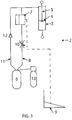
figure 3 schematically shows the energy storing prosthetic knee actuator according to the invention. - Whenever in the figures the same reference numerals are applied, these numerals refer to the same parts.
- Making reference first to
figure 1 and figure 2 auser 1 is shown respectively standing up and sitting down, and wearing an energy storingprosthetic knee actuator 2 according to the invention, comprising a hydraulic orpneumatic cylinder 3 with apiston 4 and apiston rod 5. Thepiston 4 and the hydraulic orpneumatic cylinder 3 are movable with respect to each other and are connected to an upper leg 1' andlower leg 1" of theuser 1. The connection can of course also be reversed. Preferably a pneumatic cylinder is applied because of its lower weight than an hydraulic cylinder. - Making now reference to
figure 3 , it is shown that theactuator 2 further comprises anenergy storage accumulator 6 and acontrol valve 7 provided inpiping 8 connecting the hydraulic orpneumatic cylinder 3 with theenergy storage accumulator 6. Preferably there is only a single control valve. The energy storingprosthetic knee actuator 2 of the invention thus enables assisting the standing up of theuser 1 by controlling an exchange of fluid or gas between theenergy storage accumulator 6 and the hydraulic orpneumatic cylinder 3, by executing the steps of: - providing at least one
sensor 9 for detection whether theuser 1 is seated or standing up - closing the
control valve 7 when thesensor 9 detects that the user is sitting down to maintain the stored energy in theenergy storage accumulator 6 that corresponds to the flow of fluid or gas received in theaccumulator 6 as induced by thepiston 4 moving in the hydraulic orpneumatic cylinder 3 by reason of the user's motion from standing up (figure 1 ) to sitting down (figure 2 ); and - opening the
control valve 7 when thesensor 9 detects that theuser 1 intends to stand up or is standing up for release of the stored energy from theenergy storage accumulator 6 for driving thepiston 4 and move it with respect to the hydraulic orpneumatic cylinder 3 to straighten the user's leg so that theuser 1 eventually can assume again the position shown infigure 1 . - Although it is possible to include a manual operation, the
control valve 7 operates automatically and is therefore connected to the at least onesensor 9, which is for instance provided at the bottom of thelower leg 1", for detection whether theuser 1 is in the process of standing up. According to what is mentioned above the preferablysingle control valve 7 is then suitably arranged to close off thepiping 8 between the hydraulic orpneumatic cylinder 3 and theenergy storage accumulator 6 when thesensor 9 detects that theuser 1 is seated (as shown infigure 2 ) and to open saidpiping 8 and enable again the flow of gas or fluid when the at least onesensor 9 detects that theuser 1 is in the process of standing up. It is possible to use different types of sensors, such as a mechanic, electric or a pneumatic sensor. Preferably thesensor 9 is selected from the group comprising a load sensor, an accelerometer, an inertial measurement unit, or any suitable combination of any such sensors. - One other preferable feature is that the
piston 4 is movable along and up to an extremity of thepiston rod 5. In this way thepiston 4 does not hinder extension of the knee when theuser 1 is sitting. - In addition to the application of a preferably
single control valve 7 thepiping 8 comprises advantageously a controllableflow restriction member 10 which can be used to restrict the speed of the extension of the knee. - It may also be preferable that
redundant piping 11 is provided between the hydraulic orpneumatic cylinder 3 and theenergy storage accumulator 6, in which redundant piping 11 a one-way valve 12 is included enabling a flow of fluid or gas from the hydraulic orpneumatic cylinder 3 to theenergy storage accumulator 6. This enables that theuser 1 can sit down also when thecontrol valve 7 closes off thepiping 8 between the hydraulic orpneumatic cylinder 3 and theenergy storage accumulator 6 which would otherwise prevent that thepiston 4 moves in the hydraulic orpneumatic cylinder 3 and correspondingly that the knee of theuser 1 would be bent. - Finally a high-
pressure reservoir 13 can be provided to connect to theenergy storage accumulator 6. This can compensate for possible energy losses and leakage. If desired it can also be used to extend the leg in situations that additional power is required that would otherwise have to be delivered by the user, such as when walking the stairs. - Although the invention has been discussed in the foregoing with reference to an exemplary embodiment of the energy storing prosthetic knee actuator of the invention, the invention is not restricted to this particular embodiment which can be varied in many ways without departing from the principles of the invention. The discussed exemplary embodiment shall therefore not be used to construe the appended claims strictly in accordance therewith. On the contrary the embodiment is merely intended to explain the wording of the appended claims without intent to limit the claims to this exemplary embodiment. The scope of protection of the invention shall therefore be construed in accordance with the appended claims only, wherein a possible ambiguity in the wording of the claims shall be resolved using this exemplary embodiment.
Claims (9)
- Energy storing prosthetic knee actuator (2) comprising a hydraulic or pneumatic cylinder (3) with a piston (4) and a piston rod (5), wherein the piston (4) and the hydraulic or pneumatic cylinder (3) are movable with respect to each other and are connected or connectable to a user's upper leg (1') and lower leg (1") respectively or vice versa, and further comprising an energy storage accumulator (6) and at least one control valve (7) provided in piping (8) connecting the hydraulic or pneumatic cylinder (3) with the energy storage accumulator (6) for controlling an exchange of fluid or gas between the energy storage accumulator (6) and the hydraulic or pneumatic cylinder (3), characterized in that the control valve (7) is a single control valve (7) and automatically operable and connected to at least one sensor (9) for detection whether the user (1) is standing up.
- Energy storing prosthetic knee actuator according to claim 1, characterized in that the cylinder (3) is a pneumatic cylinder.
- Energy storing prosthetic knee actuator according to claim 1 or 2, characterized in that the control valve (7) is arranged to close off the piping (8) when the sensor (9) detects that the user (1) is seated and to open the piping (8) when the sensor (9) detects that the user (1) is standing up.
- Energy storing prosthetic knee actuator according to any one of claims 1 - 3, characterized in that the sensor (9) is selected from the group comprising a load sensor, an accelerometer, an inertial measurement unit, or any suitable combination of any such sensors.
- Energy storing prosthetic knee actuator according to any one of the previous claims 1 - 4, characterized in that the piston (4) is movable along and up to an extremity of the piston rod (5).
- Energy storing prosthetic knee actuator according to any one of the previous claims 1 - 5, characterized in that in the piping (8) comprising the control valve (7) a controllable flow restriction member (10) is included.
- Energy storing prosthetic knee actuator according to any one of the previous claims 1 - 6, characterized in that it comprises redundant piping (11) between the hydraulic or pneumatic cylinder (3) and the energy storage accumulator (6), in which redundant piping (11) a one-way valve (12) is included enabling a flow of fluid or gas from the hydraulic or pneumatic cylinder (3) to the energy storage accumulator (6).
- Energy storing prosthetic knee actuator according to any one of the previous claims 1 - 7, characterized in that it comprises a high-pressure reservoir (13) connected to the energy storage accumulator (6).
- Method of using an energy storing prosthetic knee actuator (2) comprising a hydraulic or pneumatic cylinder (3) with a piston (4) and a piston rod (5), wherein the piston (4) and the hydraulic or pneumatic cylinder (3) are movable with respect to each other, said actuator (2) further comprising an energy storage accumulator (6) and a control valve (7) provided in piping (8) connecting the hydraulic or pneumatic cylinder (3) with the energy storage accumulator (6) for controlling an exchange of fluid or gas between the energy storage accumulator (6) and the hydraulic or pneumatic cylinder (3), comprising the step of:
- connecting the hydraulic or pneumatic cylinder (3) and the piston (4) to a user's upper leg (1') and lower leg (1") respectively or vice versa, and characterized by the steps of:- providing a single control valve (7);- providing at least one sensor (9) for detection whether the user (1) is seated or standing up;- closing the control valve (7) when the sensor (9) detects that the user (1) is sitting down; and- opening the control valve (7) when the sensor (9) detects that the user (1) is standing up.
Applications Claiming Priority (2)
| Application Number | Priority Date | Filing Date | Title |
|---|---|---|---|
| NL2014674A NL2014674B1 (en) | 2015-04-20 | 2015-04-20 | Energy storing prosthetic knee actuator. |
| PCT/NL2016/050273 WO2016171548A1 (en) | 2015-04-20 | 2016-04-19 | Energy storing prosthetic knee actuator |
Publications (2)
| Publication Number | Publication Date |
|---|---|
| EP3285699A1 EP3285699A1 (en) | 2018-02-28 |
| EP3285699B1 true EP3285699B1 (en) | 2019-06-19 |
Family
ID=53385895
Family Applications (1)
| Application Number | Title | Priority Date | Filing Date |
|---|---|---|---|
| EP16731369.1A Active EP3285699B1 (en) | 2015-04-20 | 2016-04-19 | Energy storing prosthetic knee actuator |
Country Status (4)
| Country | Link |
|---|---|
| US (1) | US11058559B2 (en) |
| EP (1) | EP3285699B1 (en) |
| NL (1) | NL2014674B1 (en) |
| WO (1) | WO2016171548A1 (en) |
Families Citing this family (18)
| Publication number | Priority date | Publication date | Assignee | Title |
|---|---|---|---|---|
| US10611020B2 (en) | 2013-12-19 | 2020-04-07 | Roam Robotics Inc. | Pneumatic exomuscle system and method |
| NL2014674B1 (en) | 2015-04-20 | 2017-01-20 | Univ Delft Tech | Energy storing prosthetic knee actuator. |
| US11259979B2 (en) | 2017-02-03 | 2022-03-01 | Roam Robotics Inc. | System and method for user intent recognition |
| IL272623B2 (en) | 2017-08-29 | 2024-12-01 | Roam Robotics Inc | System and method for detecting semi-guided intent |
| DE102018213481A1 (en) * | 2018-08-10 | 2020-02-13 | Audi Ag | Movement device, method for operating a movement device and method for supporting movement of the user using a movement device |
| CN109176475B (en) * | 2018-10-29 | 2020-11-06 | 北京机械设备研究所 | Hydraulic passive power assisting device for knee joint |
| DE102019122372B3 (en) | 2019-08-20 | 2021-01-14 | Ottobock Se & Co. Kgaa | Orthopedic equipment and energy storage equipment |
| IL293829B1 (en) | 2019-12-13 | 2026-04-01 | Roam Robotics Inc | Powered device to benefit a wearer during skiing |
| CN111345924A (en) * | 2020-03-23 | 2020-06-30 | 哈工大机器人湖州国际创新研究院 | Hydraulic damper for artificial limb and knee joint artificial limb |
| EP4157196A4 (en) * | 2020-05-27 | 2024-02-21 | Roam Robotics Inc. | DIRECT DRIVE OF A PNEUMATIC TRANSMISSION FOR A MOBILE ROBOT |
| IL298451A (en) | 2020-05-27 | 2023-01-01 | Roam Robotics Inc | Control system and method for a mobile robot |
| EP4157198A4 (en) | 2020-05-27 | 2024-06-26 | Roam Robotics Inc. | FITTING AND SUSPENSION SYSTEMS AND METHODS FOR A MOBILE ROBOT |
| FR3123204B1 (en) | 2021-05-27 | 2023-11-17 | Robin Temporelli | Orthopedic device comprising at least one actuator |
| CN115701796B (en) | 2021-07-21 | 2025-09-16 | 香港中文大学 | Intelligent knee joint for human lower limb exoskeleton, artificial limb and orthosis |
| WO2023023566A1 (en) | 2021-08-17 | 2023-02-23 | Roam Robotics Inc. | Maritime applications for a mobile robot |
| WO2023023563A1 (en) | 2021-08-17 | 2023-02-23 | Roam Robotics Inc. | Cable management systems and methods for a wearable mobile robot |
| US12466060B2 (en) | 2021-08-17 | 2025-11-11 | Roam Robotics Inc. | Mobile power source for a mobile robot |
| CN117357313B (en) * | 2023-12-08 | 2024-04-09 | 浙江强脑科技有限公司 | Resistance control method and device based on intention switching, artificial limb, terminal and medium |
Family Cites Families (9)
| Publication number | Priority date | Publication date | Assignee | Title |
|---|---|---|---|---|
| US3799159A (en) * | 1971-10-28 | 1974-03-26 | Us Health Education & Welfare | Hydraulic flexion control device |
| GB9813904D0 (en) * | 1997-08-15 | 1998-08-26 | Blatchford & Sons Ltd | A lower limb prosthesis |
| US6911050B2 (en) * | 2002-10-23 | 2005-06-28 | Joseph L. Molino | Prosthetic knee unit |
| DE102007032090B4 (en) * | 2007-07-09 | 2016-08-11 | Otto Bock Healthcare Gmbh | Orthopedic fluid damper |
| US8920517B2 (en) * | 2011-05-04 | 2014-12-30 | The Cleveland Clinic Foundation | Modeling and desired control of an energy-storing prosthetic knee |
| DE102012013141A1 (en) * | 2012-07-03 | 2014-05-08 | Otto Bock Healthcare Gmbh | Orthotic or prosthetic joint device and method for its control |
| US10335291B2 (en) * | 2012-07-27 | 2019-07-02 | Proteor | Hydraulic system for a knee-ankle assembly controlled by a microprocessor |
| US20180036148A1 (en) * | 2015-02-13 | 2018-02-08 | Orthocare Innovations Llc | Energy-harvesting mesofluidic impulse prosthesis |
| NL2014674B1 (en) | 2015-04-20 | 2017-01-20 | Univ Delft Tech | Energy storing prosthetic knee actuator. |
-
2015
- 2015-04-20 NL NL2014674A patent/NL2014674B1/en active
-
2016
- 2016-04-19 EP EP16731369.1A patent/EP3285699B1/en active Active
- 2016-04-19 WO PCT/NL2016/050273 patent/WO2016171548A1/en not_active Ceased
-
2017
- 2017-10-20 US US15/789,803 patent/US11058559B2/en active Active
Non-Patent Citations (1)
| Title |
|---|
| None * |
Also Published As
| Publication number | Publication date |
|---|---|
| WO2016171548A1 (en) | 2016-10-27 |
| EP3285699A1 (en) | 2018-02-28 |
| US11058559B2 (en) | 2021-07-13 |
| NL2014674B1 (en) | 2017-01-20 |
| NL2014674A (en) | 2016-10-24 |
| US20180036150A1 (en) | 2018-02-08 |
Similar Documents
| Publication | Publication Date | Title |
|---|---|---|
| US11058559B2 (en) | Energy storing prosthetic knee actuator | |
| US11998458B2 (en) | Orthotic or prosthetic joint device, and method for controlling same | |
| US20230363931A1 (en) | Method for controlling an artificial orthotic or prosthetic knee joint | |
| JP6400530B2 (en) | Prosthetic knee joint and its control method | |
| CN107548299B (en) | Method for controlling damping changes | |
| JP6880281B2 (en) | Walking robot system that regenerates energy | |
| US11963888B2 (en) | Method for controlling the standing-phase damping of an artificial knee joint | |
| KR101307265B1 (en) | Hydraulic device for wearable robot | |
| WO2007095933A8 (en) | Hip joint prosthesis | |
| EP2754383A3 (en) | Device and method for assisting laparoscopic surgery - rule based approach | |
| WO2017021965A3 (en) | Body movement feedback system and method | |
| Kim et al. | Locomotion control strategy of hydraulic lower extremity exoskeleton robot | |
| EP3678605B1 (en) | Prosthesis and orthosis | |
| JP3978972B2 (en) | Body-worn muscle strength assist device | |
| IT201800001906U1 (en) | A SYSTEM FOR CLOSING AND LOCKING SHOES, FOR EVERY USE, AND IN PARTICULAR BOOTS, WITH ROBOTIC SYSTEMS AND ARTIFICIAL INTELLIGENCE | |
| TH7270C3 (en) | Electrically adjustable, electrically damped prosthetics system | |
| TH7270A3 (en) | Electrically adjustable, electrically damped prosthetics system |
Legal Events
| Date | Code | Title | Description |
|---|---|---|---|
| STAA | Information on the status of an ep patent application or granted ep patent |
Free format text: STATUS: THE INTERNATIONAL PUBLICATION HAS BEEN MADE |
|
| PUAI | Public reference made under article 153(3) epc to a published international application that has entered the european phase |
Free format text: ORIGINAL CODE: 0009012 |
|
| STAA | Information on the status of an ep patent application or granted ep patent |
Free format text: STATUS: REQUEST FOR EXAMINATION WAS MADE |
|
| 17P | Request for examination filed |
Effective date: 20171117 |
|
| AK | Designated contracting states |
Kind code of ref document: A1 Designated state(s): AL AT BE BG CH CY CZ DE DK EE ES FI FR GB GR HR HU IE IS IT LI LT LU LV MC MK MT NL NO PL PT RO RS SE SI SK SM TR |
|
| AX | Request for extension of the european patent |
Extension state: BA ME |
|
| DAV | Request for validation of the european patent (deleted) | ||
| DAX | Request for extension of the european patent (deleted) | ||
| GRAP | Despatch of communication of intention to grant a patent |
Free format text: ORIGINAL CODE: EPIDOSNIGR1 |
|
| STAA | Information on the status of an ep patent application or granted ep patent |
Free format text: STATUS: GRANT OF PATENT IS INTENDED |
|
| RIC1 | Information provided on ipc code assigned before grant |
Ipc: A61F 2/74 20060101ALI20180920BHEP Ipc: A61F 2/76 20060101ALI20180920BHEP Ipc: A61F 2/64 20060101AFI20180920BHEP Ipc: A61F 2/68 20060101ALN20180920BHEP |
|
| INTG | Intention to grant announced |
Effective date: 20181024 |
|
| GRAJ | Information related to disapproval of communication of intention to grant by the applicant or resumption of examination proceedings by the epo deleted |
Free format text: ORIGINAL CODE: EPIDOSDIGR1 |
|
| STAA | Information on the status of an ep patent application or granted ep patent |
Free format text: STATUS: REQUEST FOR EXAMINATION WAS MADE |
|
| INTC | Intention to grant announced (deleted) | ||
| GRAS | Grant fee paid |
Free format text: ORIGINAL CODE: EPIDOSNIGR3 |
|
| STAA | Information on the status of an ep patent application or granted ep patent |
Free format text: STATUS: GRANT OF PATENT IS INTENDED |
|
| RIC1 | Information provided on ipc code assigned before grant |
Ipc: A61F 2/64 20060101AFI20190321BHEP Ipc: A61F 2/68 20060101ALN20190321BHEP Ipc: A61F 2/74 20060101ALI20190321BHEP Ipc: A61F 2/76 20060101ALI20190321BHEP |
|
| GRAP | Despatch of communication of intention to grant a patent |
Free format text: ORIGINAL CODE: EPIDOSNIGR1 |
|
| RIC1 | Information provided on ipc code assigned before grant |
Ipc: A61F 2/68 20060101ALN20190410BHEP Ipc: A61F 2/74 20060101ALI20190410BHEP Ipc: A61F 2/76 20060101ALI20190410BHEP Ipc: A61F 2/64 20060101AFI20190410BHEP |
|
| GRAA | (expected) grant |
Free format text: ORIGINAL CODE: 0009210 |
|
| STAA | Information on the status of an ep patent application or granted ep patent |
Free format text: STATUS: THE PATENT HAS BEEN GRANTED |
|
| INTG | Intention to grant announced |
Effective date: 20190429 |
|
| AK | Designated contracting states |
Kind code of ref document: B1 Designated state(s): AL AT BE BG CH CY CZ DE DK EE ES FI FR GB GR HR HU IE IS IT LI LT LU LV MC MK MT NL NO PL PT RO RS SE SI SK SM TR |
|
| REG | Reference to a national code |
Ref country code: GB Ref legal event code: FG4D |
|
| REG | Reference to a national code |
Ref country code: CH Ref legal event code: EP |
|
| REG | Reference to a national code |
Ref country code: IE Ref legal event code: FG4D |
|
| REG | Reference to a national code |
Ref country code: DE Ref legal event code: R096 Ref document number: 602016015587 Country of ref document: DE |
|
| REG | Reference to a national code |
Ref country code: AT Ref legal event code: REF Ref document number: 1144538 Country of ref document: AT Kind code of ref document: T Effective date: 20190715 |
|
| REG | Reference to a national code |
Ref country code: NL Ref legal event code: MP Effective date: 20190619 |
|
| PG25 | Lapsed in a contracting state [announced via postgrant information from national office to epo] |
Ref country code: AL Free format text: LAPSE BECAUSE OF FAILURE TO SUBMIT A TRANSLATION OF THE DESCRIPTION OR TO PAY THE FEE WITHIN THE PRESCRIBED TIME-LIMIT Effective date: 20190619 Ref country code: SE Free format text: LAPSE BECAUSE OF FAILURE TO SUBMIT A TRANSLATION OF THE DESCRIPTION OR TO PAY THE FEE WITHIN THE PRESCRIBED TIME-LIMIT Effective date: 20190619 Ref country code: FI Free format text: LAPSE BECAUSE OF FAILURE TO SUBMIT A TRANSLATION OF THE DESCRIPTION OR TO PAY THE FEE WITHIN THE PRESCRIBED TIME-LIMIT Effective date: 20190619 Ref country code: NO Free format text: LAPSE BECAUSE OF FAILURE TO SUBMIT A TRANSLATION OF THE DESCRIPTION OR TO PAY THE FEE WITHIN THE PRESCRIBED TIME-LIMIT Effective date: 20190919 Ref country code: LT Free format text: LAPSE BECAUSE OF FAILURE TO SUBMIT A TRANSLATION OF THE DESCRIPTION OR TO PAY THE FEE WITHIN THE PRESCRIBED TIME-LIMIT Effective date: 20190619 Ref country code: HR Free format text: LAPSE BECAUSE OF FAILURE TO SUBMIT A TRANSLATION OF THE DESCRIPTION OR TO PAY THE FEE WITHIN THE PRESCRIBED TIME-LIMIT Effective date: 20190619 |
|
| REG | Reference to a national code |
Ref country code: LT Ref legal event code: MG4D |
|
| PG25 | Lapsed in a contracting state [announced via postgrant information from national office to epo] |
Ref country code: RS Free format text: LAPSE BECAUSE OF FAILURE TO SUBMIT A TRANSLATION OF THE DESCRIPTION OR TO PAY THE FEE WITHIN THE PRESCRIBED TIME-LIMIT Effective date: 20190619 Ref country code: BG Free format text: LAPSE BECAUSE OF FAILURE TO SUBMIT A TRANSLATION OF THE DESCRIPTION OR TO PAY THE FEE WITHIN THE PRESCRIBED TIME-LIMIT Effective date: 20190919 Ref country code: GR Free format text: LAPSE BECAUSE OF FAILURE TO SUBMIT A TRANSLATION OF THE DESCRIPTION OR TO PAY THE FEE WITHIN THE PRESCRIBED TIME-LIMIT Effective date: 20190920 Ref country code: LV Free format text: LAPSE BECAUSE OF FAILURE TO SUBMIT A TRANSLATION OF THE DESCRIPTION OR TO PAY THE FEE WITHIN THE PRESCRIBED TIME-LIMIT Effective date: 20190619 |
|
| REG | Reference to a national code |
Ref country code: AT Ref legal event code: MK05 Ref document number: 1144538 Country of ref document: AT Kind code of ref document: T Effective date: 20190619 |
|
| PG25 | Lapsed in a contracting state [announced via postgrant information from national office to epo] |
Ref country code: NL Free format text: LAPSE BECAUSE OF FAILURE TO SUBMIT A TRANSLATION OF THE DESCRIPTION OR TO PAY THE FEE WITHIN THE PRESCRIBED TIME-LIMIT Effective date: 20190619 Ref country code: AT Free format text: LAPSE BECAUSE OF FAILURE TO SUBMIT A TRANSLATION OF THE DESCRIPTION OR TO PAY THE FEE WITHIN THE PRESCRIBED TIME-LIMIT Effective date: 20190619 Ref country code: PT Free format text: LAPSE BECAUSE OF FAILURE TO SUBMIT A TRANSLATION OF THE DESCRIPTION OR TO PAY THE FEE WITHIN THE PRESCRIBED TIME-LIMIT Effective date: 20191021 Ref country code: EE Free format text: LAPSE BECAUSE OF FAILURE TO SUBMIT A TRANSLATION OF THE DESCRIPTION OR TO PAY THE FEE WITHIN THE PRESCRIBED TIME-LIMIT Effective date: 20190619 Ref country code: CZ Free format text: LAPSE BECAUSE OF FAILURE TO SUBMIT A TRANSLATION OF THE DESCRIPTION OR TO PAY THE FEE WITHIN THE PRESCRIBED TIME-LIMIT Effective date: 20190619 Ref country code: SK Free format text: LAPSE BECAUSE OF FAILURE TO SUBMIT A TRANSLATION OF THE DESCRIPTION OR TO PAY THE FEE WITHIN THE PRESCRIBED TIME-LIMIT Effective date: 20190619 Ref country code: RO Free format text: LAPSE BECAUSE OF FAILURE TO SUBMIT A TRANSLATION OF THE DESCRIPTION OR TO PAY THE FEE WITHIN THE PRESCRIBED TIME-LIMIT Effective date: 20190619 |
|
| PG25 | Lapsed in a contracting state [announced via postgrant information from national office to epo] |
Ref country code: SM Free format text: LAPSE BECAUSE OF FAILURE TO SUBMIT A TRANSLATION OF THE DESCRIPTION OR TO PAY THE FEE WITHIN THE PRESCRIBED TIME-LIMIT Effective date: 20190619 Ref country code: IS Free format text: LAPSE BECAUSE OF FAILURE TO SUBMIT A TRANSLATION OF THE DESCRIPTION OR TO PAY THE FEE WITHIN THE PRESCRIBED TIME-LIMIT Effective date: 20191019 Ref country code: IT Free format text: LAPSE BECAUSE OF FAILURE TO SUBMIT A TRANSLATION OF THE DESCRIPTION OR TO PAY THE FEE WITHIN THE PRESCRIBED TIME-LIMIT Effective date: 20190619 Ref country code: ES Free format text: LAPSE BECAUSE OF FAILURE TO SUBMIT A TRANSLATION OF THE DESCRIPTION OR TO PAY THE FEE WITHIN THE PRESCRIBED TIME-LIMIT Effective date: 20190619 |
|
| PG25 | Lapsed in a contracting state [announced via postgrant information from national office to epo] |
Ref country code: TR Free format text: LAPSE BECAUSE OF FAILURE TO SUBMIT A TRANSLATION OF THE DESCRIPTION OR TO PAY THE FEE WITHIN THE PRESCRIBED TIME-LIMIT Effective date: 20190619 |
|
| PG25 | Lapsed in a contracting state [announced via postgrant information from national office to epo] |
Ref country code: DK Free format text: LAPSE BECAUSE OF FAILURE TO SUBMIT A TRANSLATION OF THE DESCRIPTION OR TO PAY THE FEE WITHIN THE PRESCRIBED TIME-LIMIT Effective date: 20190619 Ref country code: PL Free format text: LAPSE BECAUSE OF FAILURE TO SUBMIT A TRANSLATION OF THE DESCRIPTION OR TO PAY THE FEE WITHIN THE PRESCRIBED TIME-LIMIT Effective date: 20190619 |
|
| PG25 | Lapsed in a contracting state [announced via postgrant information from national office to epo] |
Ref country code: IS Free format text: LAPSE BECAUSE OF FAILURE TO SUBMIT A TRANSLATION OF THE DESCRIPTION OR TO PAY THE FEE WITHIN THE PRESCRIBED TIME-LIMIT Effective date: 20200224 |
|
| REG | Reference to a national code |
Ref country code: DE Ref legal event code: R097 Ref document number: 602016015587 Country of ref document: DE |
|
| PLBE | No opposition filed within time limit |
Free format text: ORIGINAL CODE: 0009261 |
|
| STAA | Information on the status of an ep patent application or granted ep patent |
Free format text: STATUS: NO OPPOSITION FILED WITHIN TIME LIMIT |
|
| PG2D | Information on lapse in contracting state deleted |
Ref country code: IS |
|
| 26N | No opposition filed |
Effective date: 20200603 |
|
| PG25 | Lapsed in a contracting state [announced via postgrant information from national office to epo] |
Ref country code: SI Free format text: LAPSE BECAUSE OF FAILURE TO SUBMIT A TRANSLATION OF THE DESCRIPTION OR TO PAY THE FEE WITHIN THE PRESCRIBED TIME-LIMIT Effective date: 20190619 |
|
| PG25 | Lapsed in a contracting state [announced via postgrant information from national office to epo] |
Ref country code: MC Free format text: LAPSE BECAUSE OF FAILURE TO SUBMIT A TRANSLATION OF THE DESCRIPTION OR TO PAY THE FEE WITHIN THE PRESCRIBED TIME-LIMIT Effective date: 20190619 |
|
| REG | Reference to a national code |
Ref country code: CH Ref legal event code: PL |
|
| PG25 | Lapsed in a contracting state [announced via postgrant information from national office to epo] |
Ref country code: LU Free format text: LAPSE BECAUSE OF NON-PAYMENT OF DUE FEES Effective date: 20200419 Ref country code: CH Free format text: LAPSE BECAUSE OF NON-PAYMENT OF DUE FEES Effective date: 20200430 Ref country code: LI Free format text: LAPSE BECAUSE OF NON-PAYMENT OF DUE FEES Effective date: 20200430 |
|
| REG | Reference to a national code |
Ref country code: BE Ref legal event code: MM Effective date: 20200430 |
|
| PG25 | Lapsed in a contracting state [announced via postgrant information from national office to epo] |
Ref country code: BE Free format text: LAPSE BECAUSE OF NON-PAYMENT OF DUE FEES Effective date: 20200430 |
|
| PG25 | Lapsed in a contracting state [announced via postgrant information from national office to epo] |
Ref country code: IE Free format text: LAPSE BECAUSE OF NON-PAYMENT OF DUE FEES Effective date: 20200419 |
|
| PG25 | Lapsed in a contracting state [announced via postgrant information from national office to epo] |
Ref country code: MT Free format text: LAPSE BECAUSE OF FAILURE TO SUBMIT A TRANSLATION OF THE DESCRIPTION OR TO PAY THE FEE WITHIN THE PRESCRIBED TIME-LIMIT Effective date: 20190619 Ref country code: CY Free format text: LAPSE BECAUSE OF FAILURE TO SUBMIT A TRANSLATION OF THE DESCRIPTION OR TO PAY THE FEE WITHIN THE PRESCRIBED TIME-LIMIT Effective date: 20190619 |
|
| PG25 | Lapsed in a contracting state [announced via postgrant information from national office to epo] |
Ref country code: MK Free format text: LAPSE BECAUSE OF FAILURE TO SUBMIT A TRANSLATION OF THE DESCRIPTION OR TO PAY THE FEE WITHIN THE PRESCRIBED TIME-LIMIT Effective date: 20190619 |
|
| P01 | Opt-out of the competence of the unified patent court (upc) registered |
Effective date: 20230511 |
|
| PGFP | Annual fee paid to national office [announced via postgrant information from national office to epo] |
Ref country code: DE Payment date: 20250428 Year of fee payment: 10 |
|
| PGFP | Annual fee paid to national office [announced via postgrant information from national office to epo] |
Ref country code: GB Payment date: 20250422 Year of fee payment: 10 |
|
| PGFP | Annual fee paid to national office [announced via postgrant information from national office to epo] |
Ref country code: FR Payment date: 20250424 Year of fee payment: 10 |