EP3285672B1 - Surgical assembly for repairing depression fractures - Google Patents
Surgical assembly for repairing depression fractures Download PDFInfo
- Publication number
- EP3285672B1 EP3285672B1 EP15802306.9A EP15802306A EP3285672B1 EP 3285672 B1 EP3285672 B1 EP 3285672B1 EP 15802306 A EP15802306 A EP 15802306A EP 3285672 B1 EP3285672 B1 EP 3285672B1
- Authority
- EP
- European Patent Office
- Prior art keywords
- cannula
- obturator
- surgical assembly
- fitting
- distal end
- Prior art date
- Legal status (The legal status is an assumption and is not a legal conclusion. Google has not performed a legal analysis and makes no representation as to the accuracy of the status listed.)
- Active
Links
- GAEUYJVHVCEFHP-UHFFFAOYSA-N CCCC1C(CC)CCC1 Chemical compound CCCC1C(CC)CCC1 GAEUYJVHVCEFHP-UHFFFAOYSA-N 0.000 description 1
Images


Classifications
-
- A—HUMAN NECESSITIES
- A61—MEDICAL OR VETERINARY SCIENCE; HYGIENE
- A61B—DIAGNOSIS; SURGERY; IDENTIFICATION
- A61B17/00—Surgical instruments, devices or methods
- A61B17/56—Surgical instruments or methods for treatment of bones or joints; Devices specially adapted therefor
- A61B17/58—Surgical instruments or methods for treatment of bones or joints; Devices specially adapted therefor for osteosynthesis, e.g. bone plates, screws or setting implements
- A61B17/88—Osteosynthesis instruments; Methods or means for implanting or extracting internal or external fixation devices
- A61B17/8866—Osteosynthesis instruments; Methods or means for implanting or extracting internal or external fixation devices for gripping or pushing bones, e.g. approximators
-
- A—HUMAN NECESSITIES
- A61—MEDICAL OR VETERINARY SCIENCE; HYGIENE
- A61B—DIAGNOSIS; SURGERY; IDENTIFICATION
- A61B17/00—Surgical instruments, devices or methods
- A61B17/34—Trocars; Puncturing needles
- A61B17/3472—Trocars; Puncturing needles for bones, e.g. intraosseus injections
-
- A—HUMAN NECESSITIES
- A61—MEDICAL OR VETERINARY SCIENCE; HYGIENE
- A61B—DIAGNOSIS; SURGERY; IDENTIFICATION
- A61B17/00—Surgical instruments, devices or methods
- A61B17/56—Surgical instruments or methods for treatment of bones or joints; Devices specially adapted therefor
- A61B17/58—Surgical instruments or methods for treatment of bones or joints; Devices specially adapted therefor for osteosynthesis, e.g. bone plates, screws or setting implements
- A61B17/88—Osteosynthesis instruments; Methods or means for implanting or extracting internal or external fixation devices
- A61B17/8802—Equipment for handling bone cement or other fluid fillers
- A61B17/8805—Equipment for handling bone cement or other fluid fillers for introducing fluid filler into bone or extracting it
- A61B17/8811—Equipment for handling bone cement or other fluid fillers for introducing fluid filler into bone or extracting it characterised by the introducer tip, i.e. the part inserted into or onto the bone
-
- A—HUMAN NECESSITIES
- A61—MEDICAL OR VETERINARY SCIENCE; HYGIENE
- A61B—DIAGNOSIS; SURGERY; IDENTIFICATION
- A61B17/00—Surgical instruments, devices or methods
- A61B17/56—Surgical instruments or methods for treatment of bones or joints; Devices specially adapted therefor
- A61B17/58—Surgical instruments or methods for treatment of bones or joints; Devices specially adapted therefor for osteosynthesis, e.g. bone plates, screws or setting implements
- A61B17/88—Osteosynthesis instruments; Methods or means for implanting or extracting internal or external fixation devices
- A61B17/8802—Equipment for handling bone cement or other fluid fillers
- A61B17/8805—Equipment for handling bone cement or other fluid fillers for introducing fluid filler into bone or extracting it
- A61B17/8819—Equipment for handling bone cement or other fluid fillers for introducing fluid filler into bone or extracting it characterised by the introducer proximal part, e.g. cannula handle, or by parts which are inserted inside each other, e.g. stylet and cannula
-
- A—HUMAN NECESSITIES
- A61—MEDICAL OR VETERINARY SCIENCE; HYGIENE
- A61B—DIAGNOSIS; SURGERY; IDENTIFICATION
- A61B17/00—Surgical instruments, devices or methods
- A61B17/56—Surgical instruments or methods for treatment of bones or joints; Devices specially adapted therefor
- A61B17/58—Surgical instruments or methods for treatment of bones or joints; Devices specially adapted therefor for osteosynthesis, e.g. bone plates, screws or setting implements
- A61B17/88—Osteosynthesis instruments; Methods or means for implanting or extracting internal or external fixation devices
- A61B17/8802—Equipment for handling bone cement or other fluid fillers
- A61B17/8805—Equipment for handling bone cement or other fluid fillers for introducing fluid filler into bone or extracting it
- A61B17/8816—Equipment for handling bone cement or other fluid fillers for introducing fluid filler into bone or extracting it characterised by the conduit, e.g. tube, along which fluid flows into the body or by conduit connections
-
- A—HUMAN NECESSITIES
- A61—MEDICAL OR VETERINARY SCIENCE; HYGIENE
- A61B—DIAGNOSIS; SURGERY; IDENTIFICATION
- A61B17/00—Surgical instruments, devices or methods
- A61B17/34—Trocars; Puncturing needles
- A61B17/3417—Details of tips or shafts, e.g. grooves, expandable, bendable; Multiple coaxial sliding cannulas, e.g. for dilating
- A61B2017/3454—Details of tips
- A61B2017/3456—Details of tips blunt
Definitions
- US2011/0015675 describes a system for implanting an anchor into bone, the system comprising a curved cannulated guide for percautaneous insertion, having a proximal end and a distal end; a flexible drill insertable through the curved guide from the proximal end to the distal end, the flexible drill having a shaft having a flexible portion; and a flexible inserter for inserting a suture anchor into a bore at the anatomical site formed by the flexible drill, the flexible inserter having a shaft having a flexible portion, wherein the flexible portions of both the flexible drill and flexible inserter include a series of discrete, interlocking segments.
- Prolonged periods of high force impact and stress during sporting activities can result in depression fractures in the articulating surfaces of joints.
- Collapsed bone fragments associated with the depression fracture can depress into softer cancellous bone located beneath relatively hard cortical bone.
- the collapsed bone fragments must be returned to their original anatomical position to stabilize the joint and minimize the risk of post traumatic osteoarthritis.
- a surgical assembly includes, among other things, a cannula and an obturator receivable through the cannula and configured to manipulate a depressed bone fragment associated with a depression fracture.
- the obturator includes a blunt tip that extends beyond a distal end of the cannula.
- the blunt tip is rounded.
- the blunt tip and the distal end are curved and extend along an axis that is transverse to a longitudinal axis of the surgical assembly.
- the cannula includes a tube that extends between a fitting and a distal end.
- the tube includes a passage that extends between the fitting and the distal end.
- a plurality of openings are formed through the tube at the distal end.
- the obturator includes a shaft that extends between a handle and a blunt tip.
- the handle includes a fitting and a grip that extends from the fitting.
- the obturator is removable from the cannula.
- the assembly includes a delivery device for injecting a repair material through the cannula after removing the obturator.
- the cannula includes a first fitting and the obturator includes a second fitting configured to engage the first fitting to connect the obturator to the cannula.
- a surgical method for using the present invention includes, among other things, accessing a depressed bone fragment of a depression fracture with a surgical assembly.
- the surgical assembly includes a cannula and an obturator receivable through the cannula.
- the method further includes positioning the depressed bone fragment toward its original anatomical position using a blunt tip of the obturator.
- the accessing step includes locating the blunt tip of the obturator beneath the depressed bone fragment.
- the locating step includes positioning the blunt tip such that it is generally perpendicular to the depressed bone fragment.
- the method includes, prior to the accessing step, forming a pilot hole through cortical bone that is located inferior to the depression fracture.
- the method includes, subsequent to the positioning step, removing the obturator from the cannula.
- the method includes injecting a repair material through the cannula after the removing step.
- the blunt tip extends past a distal end of the cannula.
- the positioning step includes raising the depressed bone fragment toward the original anatomical position.
- a surgical assembly includes a cannula and an obturator receivable through the cannula and configured to manipulate a depressed bone fragment associated with a depression fracture.
- the obturator includes a blunt tip that extends beyond a distal end of the cannula.
- the cannula may include a tube that extends between a fitting and a distal end.
- the tube includes a passage that extends between the fitting and the distal end.
- the obturator may include a shaft that extends between a handle and a blunt tip.
- the cannula may include a tube that extends between a fitting and a distal end and the obturator may include a shaft that extends between a handle and a blunt tip.
- the obturator includes a blunt tip that extends beyond a distal end of the cannula
- the cannula may include a tube that extends between a fitting and a distal end and the obturator may include a shaft that extends between a handle and a blunt tip.
- the obturator is removable from the cannula.
- the cannula may include a first fitting and the obturator may include a second fitting configured to engage the first fitting to connect the obturator to the cannula.
- the obturator includes a blunt tip that extends beyond a distal end of the cannula and the obturator is removable from the cannula and/or the cannula may include a first fitting and the obturator may include a second fitting configured to engage the first fitting to connect the obturator to the cannula.
- the surgical assembly includes a delivery device for injecting a repair material through the cannula after removing the obturator.
- the obturator includes a blunt tip that extends beyond a distal end of the cannula
- the cannula includes a tube that extends between a fitting and a distal end, the tube including a passage that extends between the fitting and the distal end
- the obturator includes a shaft that extends between a handle and a blunt tip
- the obturator is removable from the cannula, for example where the cannula includes a first fitting and the obturator includes a second fitting configured to engage the first fitting to connect the obturator to the cannula.
- Such an assembly may also include, for example, a delivery device for injecting a repair material through the cannula after removing the obturator.
- the blunt tip may be rounded, the blunt tip and the distal end of the cannula are curved and extend along an axis that is transverse to a longitudinal axis of the surgical assembly, a plurality of openings may be formed through the tube at the distal end, and the handle of the obturator may include a fitting and a grip that extends from the fitting.
- the obturator includes a rounded blunt tip that extends beyond a distal end of the cannula, the blunt tip and the distal end of the cannula are curved and extend along an axis that is transverse to a longitudinal axis of the surgical assembly, the cannula includes a tube that extends between a fitting and a distal end, the tube including a passage that extends between the fitting and the distal end, where a plurality of openings are formed through the tube at the distal end, the obturator includes a shaft that extends between a handle and a blunt tip, where the handle of the obturator includes a fitting and a grip that extends from the fitting, and the obturator is removable from the cannula, for example where the cannula includes a first fitting and the obturator includes a second fitting configured to engage the first fitting to connect the obturator to the cannula.
- Such an assembly includes a delivery device
- a surgical method includes accessing a depressed bone fragment of a depression fracture with a surgical assembly, where the surgical assembly includes a cannula and an obturator receivable through the cannula, and the method further includes positioning the depressed bone fragment toward its original anatomical position using a blunt tip of the obturator.
- the accessing step may include locating the blunt tip of the obturator beneath the depressed bone fragment.
- the surgical method may include, prior to the accessing step, forming a pilot hole through cortical bone that is located inferior to the depression fracture.
- the surgical method may include, subsequent to the positioning step, removing the obturator from the cannula.
- the surgical method may include locating the blunt tip of the obturator beneath the depressed bone fragment and may also include, prior to the accessing step, forming a pilot hole through cortical bone that is located inferior to the depression fracture and/or, subsequent to the positioning step, removing the obturator from the cannula.
- the surgical method may also include injecting a repair material through the cannula after the removing step.
- the locating step may include positioning the blunt tip such that it is generally perpendicular to the depressed bone fragment and the positioning step may include raising the depressed bone fragment toward the original anatomical position, and the blunt tip of the obturator may extend past a distal end of the cannula.
- the surgical method includes locating the blunt tip of the obturator beneath the depressed bone fragment, where the blunt tip extends past a distal end of the cannula, where the locating step includes positioning the blunt tip such that it is generally perpendicular to the depressed bone fragment and the positioning step includes raising the depressed bone fragment toward the original anatomical position, and also includes, prior to the accessing step, forming a pilot hole through cortical bone that is located inferior to the depression fracture and/or, subsequent to the positioning step, removing the obturator from the cannula and optionally further injecting a repair material through the cannula after removing the obturator.
- an exemplary surgical assembly of the present disclosure includes a cannula and an obturator removably received within the cannula.
- a passage may extend entirely through the cannula.
- the obturator is insertable through the passage.
- the obturator may be removably attachable to the cannula.
- the obturator includes a blunt tip that extends past a distal end of the cannula.
- the cannula may include a tube that extends along a longitudinal axis of the surgical assembly between a fitting, disposed proximally, and the distal end.
- the fitting of the cannula may include a grip.
- the obturator may include a shaft that extends along the longitudinal axis between a handle and the blunt tip.
- the handle of the obturator may include a fitting and a grip.
- the surgical assembly is for reducing a depression fracture, such as of a musculoskeletal joint.
- the obturator which is removably receivable within the cannula is configured to position a depressed bone fragment, such that the depressed bone fragment may be accessed and elevated to its original anatomical position using the surgical assembly.
- the obturator is insertable through the passage to access depressed bone fragments associated with a depression fracture.
- the blunt tip is configured to position depressed bone fragment(s) associated with a depression fracture.
- the fitting of the cannula is configured for connection to the obturator.
- the grip of the cannula fitting is configured for gripping the cannula.
- the fitting of the obturator is adapted to connect to the fitting of the cannula and the grip of the obturator is configured for gripping the surgical assembly.
- the cannula and obturator may be connected together using a luer connection. Other connections, however, are also contemplated within the scope of this disclosure.
- the blunt tip may be configured as a non-traumatic tip designed to avoid damaging the depressed bone fragments. For example, the blunt tip is rounded. However, other non-traumatic shapes are also contemplated within the scope of this disclosure.
- Both the distal end of the cannula and the blunt tip of the obturator are curved. For example, the distal end and the blunt tip are both curved such that they extend at a transverse angle relative to a longitudinal axis of the surgical assembly. The actual angle of the curvature may vary depending on the joint being repaired, among other factors.
- the distal end of the cannula and the blunt tip of the obturator may be pre-bent or can be bent in the operating room just prior to performing a depression fracture reduction surgery.
- At the distal end of the cannula there may be a plurality of openings, or fenestrations, formed through the tube. The plurality of openings are in fluid communication with the passage that extends through the tube.
- the fitting of the cannula configured for connection to the obturator is, for example, a male luer lock fitting that may be rotatably received within a female luer lock fitting of the obturator.
- the handle of the obturator may include any size, shape and/or configuration. In other words, the handle is not limited to specific exemplary configurations.
- the cannula may be made of a metallic material, such as stainless steel.
- the cannula may be made of a non-metallic material, such as a plastic.
- the tube and the fitting of the cannula may be made of either similar or dissimilar materials.
- the obturator may be made of a metallic material, such as stainless steel. Other metallic materials may also be suitable.
- the shaft and the fitting of the obturator may be made of similar or dissimilar materials.
- an exemplary surgical method for reducing a depression fracture of a joint of the present disclosure includes accessing the depressed bone fragment and elevating it to its original anatomical position using a surgical assembly of the present disclosure.
- the joint is a knee joint that includes a femur and a tibia and the depression fracture is a depression fracture of the tibial plateau.
- the depression fracture could alternatively be a fracture associated with a Hill Sachs lesion, the calcaneus, the distal radius, or any other bone or joint.
- the phrase "depression fracture” indicates a fracture in which one or more bone fragments depress into the softer cancellous bone located beneath relatively hard cortical bone. The depressed bone fragment(s) must be returned to their original anatomical position to stabilize the joint.
- the surgical method of the present disclosure may be performed as either an arthroscopic method or an open method.
- the method may include forming a pilot hole through the cortical bone.
- the method may include guidance of the surgical assembly through the pilot hole.
- the method may include manipulating the depressed bone fragment(s) back to an original anatomical position.
- the method may include disconnecting the obturator from the cannula and then removing the obturator from the joint after reducing the depressed bone fragments.
- the method may include injecting into the joint a repair material to backfill the hollow area immediately beneath the bone fragment(s) of the depression fracture.
- the method may include removing the cannula from the joint to complete the depression fracture reduction procedure.
- a pilot hole may be formed through the cortical bone.
- the pilot hole provides an opening through which the depressed bone fragment(s) associated with the depression fracture may be accessed using the surgical assembly.
- the pilot hole is formed at approximately a 45° angle at a location of the cortical bone that is inferior to (i.e., below) the depression fracture.
- the pilot hole is formed on the same side of the joint as the depression fracture.
- the pilot hole is formed on the medial side of the tibia if the depression fracture is located medially and is formed on the lateral side of the tibia if the depression fracture is located laterally.
- the location of the pilot hole may be chosen with the aid of fluoroscopic imaging techniques that provide a real-time understanding of the positioning of the depressed bone fragments and the various other structures that make-up the joint.
- the tube of the cannula may include an outer diameter that is smaller than the pilot hole to ease insertion of the surgical assembly into the joint.
- the handle of the obturator and/or the grip of the cannula may be used to guide the surgical assembly to a desired positioning beneath the depressed bone fragment(s).
- the handle and/or the grip also provide sufficient leverage for inserting and guiding the surgical assembly through the cancellous bone to access the depression fracture.
- the surgical assembly may be used to manipulate the depressed bone fragment(s) back to an original anatomical position.
- the blunt tip of the obturator may be used to reduce the depressed bone fragment(s) as close as is possible back to an original anatomical position.
- the handle of the obturator and/or the grip of the cannula provide sufficient leverage for lifting the depressed bone fragments of the depression fracture.
- the blunt tip may approach the depression fracture at a perpendicular angle relative to the depressed bone fragments. Approaching the bone fragments at such an angle simplifies manipulation of the depressed bone fragments for improved approximation back toward the original anatomical position.
- the obturator may be disconnected from the cannula and then removed from the joint after reducing the depressed bone fragments.
- the cannula may be left inside the joint for performing additional surgical steps.
- a repair material may be injected into the joint to backfill the hollow area immediately beneath the bone fragments of the depression fracture, which have been lifted back toward their original anatomical position.
- the repair material may be delivered using a delivery device that can be inserted into and through the cannula.
- the delivery device may include a syringe and tube, in one example.
- the repair material may flow through the passage of the cannula and then out of the openings at the distal end as well as the open distal end.
- the repair material may include resorbable or non-resorbable bone cement, a bone graft, a bone plug allograft or an autologous material. These, of course, are intended as non-limiting examples of suitable materials.
- the cannula is removed from the joint to complete the depression fracture reduction procedure.
- the surgical assembly includes a cannula and an obturator receivable through the cannula and configured to position a depressed bone fragment.
- the depressed bone fragment may be accessed and elevated to its original anatomical position using the surgical assembly.
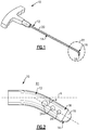
- Figures 1 and 2 illustrate a surgical assembly 10 for reducing a depression fracture.
- the surgical assembly 10 includes a cannula 12 and an obturator 14 removably received within the cannula 12.
- a passage 20 may extend entirely through the cannula 12.
- the cannula 12 is cannulated.
- the obturator 14 is insertable through the passage 20 to access depressed bone fragments associated with a depression fracture.
- the obturator 14 is removably attachable to the cannula 12.
- the cannula 12 and obturator 14 may be connected together using a luer connection. Other connections; however, are also contemplated within the scope of this disclosure.
- the obturator 14 includes a blunt tip 16 that extends past a distal end 18 of the cannula 12.
- the blunt tip 16 is configured to position depressed bone fragment(s) associated with a depression fracture.
- the blunt tip 16 is configured as a non-traumatic tip designed to avoid damaging the depressed bone fragments.
- both the distal end 18 of the cannula 12 and the blunt tip 16 of the obturator 14 are curved.
- the distal end 18 and the blunt tip 16 are both curved such that they extend at a transverse angle ⁇ relative to a longitudinal axis A of the surgical assembly 10.
- the actual angle of the curvature may vary depending on the joint being repaired, among other factors.
- the distal end 18 of the cannula 12 and the blunt tip 16 of the obturator 14 may be pre-bent or can be bent in the operating room just prior to performing a depression fracture reduction surgery.
- FIG 3 further illustrates the cannula 12 of the surgical assembly 10.
- the cannula 12 includes a tube 15 that extends along the longitudinal axis A between a fitting 22, disposed proximally, and the distal end 18.
- the distal end 18 of the cannula 12 may include a plurality of openings 24, or fenestrations, formed through the tube 15.
- the plurality of openings 24 are in fluid communication with the passage 20 that extends through the tube 15.
- the fitting 22 is configured for connection to the obturator 14.
- the fitting 22 is a male luer lock fitting that may be rotatably received within a female luer lock fitting of the obturator 14.
- Other fitting configurations are also contemplated, including an embodiment in which the fitting 22 of the cannula 12 provides the female connection and the obturator 14 provides the male connection.
- the fitting 22 includes a grip 17 for gripping the cannula 12 (see, for example, the embodiment of Figure 5 ).
- the cannula 12 is made of a metallic material, such as stainless steel. In another embodiment, the cannula 12 may be made of a non-metallic material, such as a plastic.
- the tube 15 and the fitting 22 of the cannula 12 may be made of either similar or dissimilar materials.
- FIG 4 further illustrates the obturator 14 of the surgical assembly 10.
- the obturator 14 includes a shaft 25 that extends along the longitudinal axis A between a handle 26 and the blunt tip 16.
- the blunt tip 16 is rounded.
- other non-traumatic shapes are also contemplated within the scope of this disclosure.
- the handle 26 may include any size, shape and/or configuration. In other words, the handle 26 is not limited to the specific configurations shown in Figure 4 or Figure 5 , which illustrate two non-limiting handle configurations.
- the handle 26 may include a fitting 28 and a grip 30.
- the fitting 28 is adapted to connect to the fitting 22 of the cannula 12 (see Figures 1 and 5 ) and the grip 30 is configured for gripping the surgical assembly 10.
- the obturator 14 is made of a metallic material, such as stainless steel. Other metallic materials may also be suitable.
- the shaft 25 and the fitting 28 of the obturator 14 may be made of similar or dissimilar materials.
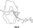
- Figures 6-10 schematically illustrate a method for reducing a depression fracture 32 of a joint 34.
- the joint 34 is a knee joint that includes a femur 36 and a tibia 38 and the depression fracture 32 is a depression fracture of the tibial plateau 40.
- the depression fracture 32 could alternatively be a fracture associated with a Hill Sachs lesion, the calcaneus, the distal radius, or any other bone or joint.
- the phrase "depression fracture” indicates a fracture in which one or more bone fragments 45 depress into the softer cancellous bone 42 located beneath relatively hard cortical bone 44. The depressed bone fragment(s) 45 must be returned to their original anatomical position to stabilize the joint 34.
- the method shown in Figures 6-10 may be performed as either an arthroscopic method or an open method.
- a pilot hole 46 is formed through the cortical bone 44.
- the pilot hole 46 provides an opening through which the depressed bone fragment(s) 45 associated with the depression fracture 32 may be accessed using the surgical assembly 10.
- the pilot hole 46 is formed at approximately a 45° angle at a location of the cortical bone 44 that is inferior to (i.e., below) the depression fracture 32.
- the pilot hole 46 is formed on the same side of the joint 34 as the depression fracture 32.
- the pilot hole 46 is formed on the medial side of the tibia 38 if the depression fracture 32 is located medially and is formed on the lateral side of the tibia 38 if the depression fracture 32 is located laterally.
- the location of the pilot hole 46 may be chosen with the aid of fluoroscopic imaging techniques that provide a real-time understanding of the positioning of the depressed bone fragments 45 and the various other structures that make-up the joint 34.
- Figure 7 schematically illustrates guidance of the surgical assembly 10 through the pilot hole 46 for accessing the depressed bone fragment(s) 45.
- the tube 15 of the cannula 12 includes an outer diameter that is smaller than the pilot hole 46 to ease insertion of the surgical assembly 10 into the joint 34.
- the handle 26 of the obturator 14 and/or the grip 17 of the cannula 12 may be used to guide the surgical assembly 10 to a desired positioning beneath the depressed bone fragment(s) 45.
- the handle 26 and/or the grip 17 also provide sufficient leverage for inserting and guiding the surgical assembly 10 through the cancellous bone 42 to access the depression fracture 32.
- the surgical assembly 10 may be used to manipulate the depressed bone fragment(s) 45 back to an original anatomical positon.
- the blunt tip 16 of the obturator 14 may be used to reduce the depressed bone fragment(s) 45 as close as is possible back to an original anatomical position 50 (shown schematically in dashed lines in Figure 8 ).
- the handle 26 of the obturator 14 and/or the grip 17 of the cannula 12 provide sufficient leverage for lifting the depressed bone fragments 45 of the depression fracture 32.
- the blunt tip 16 may approach the depression fracture 32 at a perpendicular angle relative to the depressed bone fragments 45. Approaching the bone fragments 45 at such an angle simplifies manipulation of the depressed bone fragments 45 for improved approximation back toward the original anatomical position 50.
- the obturator 14 may be disconnected from the cannula 12 and then removed from the joint 34 after reducing the depressed bone fragments 45.
- the cannula 12, however, may be left inside the joint 34 for preforming additional surgical steps.
- a repair material 60 may be injected into the joint 34 to backfill the hollow area immediately beneath the bone fragments 45 of the depression fracture 32, which have not been lifted back toward their original anatomical position.
- the repair material 60 is delivered using a delivery device 62 that can be inserted into and through the cannula 12.
- the delivery device 62 may include a syringe and tube, in one non-limiting embodiment.
- the repair material 60 may flow through the passage 20 of the cannula 12 and then out of the openings 24 as well as the open distal end 18 (see Figure 3 ).
- the repair material 60 may include resorbable or non-resorbable bone cement, a bone graft, a bone plug allograft or an autologous material. These, of course, are intended as non-limiting examples of suitable materials.
- the cannula 12 is removed from the joint 34 to complete the depression fracture reduction procedure.
Landscapes
- Health & Medical Sciences (AREA)
- Surgery (AREA)
- Life Sciences & Earth Sciences (AREA)
- Orthopedic Medicine & Surgery (AREA)
- Heart & Thoracic Surgery (AREA)
- Nuclear Medicine, Radiotherapy & Molecular Imaging (AREA)
- Engineering & Computer Science (AREA)
- Biomedical Technology (AREA)
- Medical Informatics (AREA)
- Molecular Biology (AREA)
- Animal Behavior & Ethology (AREA)
- General Health & Medical Sciences (AREA)
- Public Health (AREA)
- Veterinary Medicine (AREA)
- Pathology (AREA)
- Surgical Instruments (AREA)
Description
- This disclosure relates to a surgical assembly and method for reducing depression fractures.
US2011/0015675 describes a system for implanting an anchor into bone, the system comprising a curved cannulated guide for percautaneous insertion, having a proximal end and a distal end; a flexible drill insertable through the curved guide from the proximal end to the distal end, the flexible drill having a shaft having a flexible portion; and a flexible inserter for inserting a suture anchor into a bore at the anatomical site formed by the flexible drill, the flexible inserter having a shaft having a flexible portion, wherein the flexible portions of both the flexible drill and flexible inserter include a series of discrete, interlocking segments. - Prolonged periods of high force impact and stress during sporting activities can result in depression fractures in the articulating surfaces of joints. Collapsed bone fragments associated with the depression fracture can depress into softer cancellous bone located beneath relatively hard cortical bone. The collapsed bone fragments must be returned to their original anatomical position to stabilize the joint and minimize the risk of post traumatic osteoarthritis.
- The present invention is defined in claim 1. A surgical assembly according to an exemplary aspect of the present disclosure includes, among other things, a cannula and an obturator receivable through the cannula and configured to manipulate a depressed bone fragment associated with a depression fracture.
- The obturator includes a blunt tip that extends beyond a distal end of the cannula.
- In a further non-limiting embodiment of either of the foregoing surgical assemblies, the blunt tip is rounded.
- The blunt tip and the distal end are curved and extend along an axis that is transverse to a longitudinal axis of the surgical assembly.
- In a further non-limiting embodiment of any of the foregoing surgical assemblies, the cannula includes a tube that extends between a fitting and a distal end.
- In a further non-limiting embodiment of any of the foregoing surgical assemblies, the tube includes a passage that extends between the fitting and the distal end.
- In a further non-limiting embodiment of any of the foregoing surgical assemblies, a plurality of openings are formed through the tube at the distal end.
- In a further non-limiting embodiment of any of the foregoing surgical assemblies, the obturator includes a shaft that extends between a handle and a blunt tip.
- In a further non-limiting embodiment of any of the foregoing surgical assemblies, the handle includes a fitting and a grip that extends from the fitting.
- The obturator is removable from the cannula.
- The assembly includes a delivery device for injecting a repair material through the cannula after removing the obturator.
- In a further non-limiting embodiment of any of the foregoing surgical assemblies, the cannula includes a first fitting and the obturator includes a second fitting configured to engage the first fitting to connect the obturator to the cannula.
- A surgical method for using the present invention includes, among other things, accessing a depressed bone fragment of a depression fracture with a surgical assembly. The surgical assembly includes a cannula and an obturator receivable through the cannula. The method further includes positioning the depressed bone fragment toward its original anatomical position using a blunt tip of the obturator.
- In a further example of the foregoing surgical method, the accessing step includes locating the blunt tip of the obturator beneath the depressed bone fragment.
- In a further example of either of the foregoing surgical methods, the locating step includes positioning the blunt tip such that it is generally perpendicular to the depressed bone fragment.
- In a further example of any of the foregoing surgical methods, the method includes, prior to the accessing step, forming a pilot hole through cortical bone that is located inferior to the depression fracture.
- In a further example of any of the foregoing surgical methods, the method includes, subsequent to the positioning step, removing the obturator from the cannula.
- In a further non-limiting embodiment of any of the foregoing surgical methods, the method includes injecting a repair material through the cannula after the removing step.
- In a further example of any of the foregoing surgical methods, the blunt tip extends past a distal end of the cannula.
- In a further example of any of the foregoing surgical methods, the positioning step includes raising the depressed bone fragment toward the original anatomical position.
- The embodiments, examples and alternatives of the preceding paragraphs, or the following description and drawings, including any of their various aspects or respective individual features, may be taken independently or in any combination. Features described in connection with one embodiment are applicable to all embodiments, unless such features are incompatible.
- Accordingly, a surgical assembly according to an exemplary aspect of the present disclosure includes a cannula and an obturator receivable through the cannula and configured to manipulate a depressed bone fragment associated with a depression fracture.
- In the surgical assembly, the obturator includes a blunt tip that extends beyond a distal end of the cannula. In the surgical assembly, the cannula may include a tube that extends between a fitting and a distal end. The tube includes a passage that extends between the fitting and the distal end. In the surgical assembly, the obturator may include a shaft that extends between a handle and a blunt tip. In the surgical assembly, the cannula may include a tube that extends between a fitting and a distal end and the obturator may include a shaft that extends between a handle and a blunt tip. In the surgical assembly, the obturator includes a blunt tip that extends beyond a distal end of the cannula, the cannula may include a tube that extends between a fitting and a distal end and the obturator may include a shaft that extends between a handle and a blunt tip. In the surgical assembly, the obturator is removable from the cannula. In the surgical assembly, the cannula may include a first fitting and the obturator may include a second fitting configured to engage the first fitting to connect the obturator to the cannula. In the surgical assembly, the obturator includes a blunt tip that extends beyond a distal end of the cannula and the obturator is removable from the cannula and/or the cannula may include a first fitting and the obturator may include a second fitting configured to engage the first fitting to connect the obturator to the cannula. The surgical assembly includes a delivery device for injecting a repair material through the cannula after removing the obturator. For example, in the surgical assembly, the obturator includes a blunt tip that extends beyond a distal end of the cannula, the cannula includes a tube that extends between a fitting and a distal end, the tube including a passage that extends between the fitting and the distal end, the obturator includes a shaft that extends between a handle and a blunt tip, and the obturator is removable from the cannula, for example where the cannula includes a first fitting and the obturator includes a second fitting configured to engage the first fitting to connect the obturator to the cannula. Such an assembly may also include, for example, a delivery device for injecting a repair material through the cannula after removing the obturator.
- In a surgical assembly also having one or more of these further features, the blunt tip may be rounded, the blunt tip and the distal end of the cannula are curved and extend along an axis that is transverse to a longitudinal axis of the surgical assembly, a plurality of openings may be formed through the tube at the distal end, and the handle of the obturator may include a fitting and a grip that extends from the fitting. For example, in the surgical assembly, the obturator includes a rounded blunt tip that extends beyond a distal end of the cannula, the blunt tip and the distal end of the cannula are curved and extend along an axis that is transverse to a longitudinal axis of the surgical assembly, the cannula includes a tube that extends between a fitting and a distal end, the tube including a passage that extends between the fitting and the distal end, where a plurality of openings are formed through the tube at the distal end, the obturator includes a shaft that extends between a handle and a blunt tip, where the handle of the obturator includes a fitting and a grip that extends from the fitting, and the obturator is removable from the cannula, for example where the cannula includes a first fitting and the obturator includes a second fitting configured to engage the first fitting to connect the obturator to the cannula. Such an assembly includes a delivery device for injecting a repair material through the cannula after removing the obturator.
- A surgical method includes accessing a depressed bone fragment of a depression fracture with a surgical assembly, where the surgical assembly includes a cannula and an obturator receivable through the cannula, and the method further includes positioning the depressed bone fragment toward its original anatomical position using a blunt tip of the obturator.
- In the surgical method, the accessing step may include locating the blunt tip of the obturator beneath the depressed bone fragment. The surgical method may include, prior to the accessing step, forming a pilot hole through cortical bone that is located inferior to the depression fracture. The surgical method may include, subsequent to the positioning step, removing the obturator from the cannula. The surgical method may include locating the blunt tip of the obturator beneath the depressed bone fragment and may also include, prior to the accessing step, forming a pilot hole through cortical bone that is located inferior to the depression fracture and/or, subsequent to the positioning step, removing the obturator from the cannula. The surgical method may also include injecting a repair material through the cannula after the removing step.
- In a surgical method also having any one or more of these further features, the locating step may include positioning the blunt tip such that it is generally perpendicular to the depressed bone fragment and the positioning step may include raising the depressed bone fragment toward the original anatomical position, and the blunt tip of the obturator may extend past a distal end of the cannula. For example, the surgical method includes locating the blunt tip of the obturator beneath the depressed bone fragment, where the blunt tip extends past a distal end of the cannula, where the locating step includes positioning the blunt tip such that it is generally perpendicular to the depressed bone fragment and the positioning step includes raising the depressed bone fragment toward the original anatomical position, and also includes, prior to the accessing step, forming a pilot hole through cortical bone that is located inferior to the depression fracture and/or, subsequent to the positioning step, removing the obturator from the cannula and optionally further injecting a repair material through the cannula after removing the obturator.
- Aspects, features and embodiments of the present disclosure are described further below.
- For example, an exemplary surgical assembly of the present disclosure includes a cannula and an obturator removably received within the cannula. A passage may extend entirely through the cannula. In other words, the cannula is cannulated. The obturator is insertable through the passage. The obturator may be removably attachable to the cannula. The obturator includes a blunt tip that extends past a distal end of the cannula. The cannula may include a tube that extends along a longitudinal axis of the surgical assembly between a fitting, disposed proximally, and the distal end. The fitting of the cannula may include a grip. The obturator may include a shaft that extends along the longitudinal axis between a handle and the blunt tip. The handle of the obturator may include a fitting and a grip.
- The surgical assembly is for reducing a depression fracture, such as of a musculoskeletal joint. The obturator which is removably receivable within the cannula is configured to position a depressed bone fragment, such that the depressed bone fragment may be accessed and elevated to its original anatomical position using the surgical assembly. Thus, the obturator is insertable through the passage to access depressed bone fragments associated with a depression fracture. The blunt tip is configured to position depressed bone fragment(s) associated with a depression fracture. The fitting of the cannula is configured for connection to the obturator. The grip of the cannula fitting is configured for gripping the cannula. The fitting of the obturator is adapted to connect to the fitting of the cannula and the grip of the obturator is configured for gripping the surgical assembly.
- The cannula and obturator may be connected together using a luer connection. Other connections, however, are also contemplated within the scope of this disclosure. The blunt tip may be configured as a non-traumatic tip designed to avoid damaging the depressed bone fragments. For example, the blunt tip is rounded. However, other non-traumatic shapes are also contemplated within the scope of this disclosure. Both the distal end of the cannula and the blunt tip of the obturator are curved. For example, the distal end and the blunt tip are both curved such that they extend at a transverse angle relative to a longitudinal axis of the surgical assembly. The actual angle of the curvature may vary depending on the joint being repaired, among other factors. The distal end of the cannula and the blunt tip of the obturator may be pre-bent or can be bent in the operating room just prior to performing a depression fracture reduction surgery. At the distal end of the cannula, there may be a plurality of openings, or fenestrations, formed through the tube. The plurality of openings are in fluid communication with the passage that extends through the tube. The fitting of the cannula configured for connection to the obturator, is, for example, a male luer lock fitting that may be rotatably received within a female luer lock fitting of the obturator. Other fitting configurations are also contemplated, including an example in which the fitting of the cannula provides the female connection and the obturator provides the male connection. The handle of the obturator may include any size, shape and/or configuration. In other words, the handle is not limited to specific exemplary configurations.
- The cannula may be made of a metallic material, such as stainless steel. The cannula may be made of a non-metallic material, such as a plastic. The tube and the fitting of the cannula may be made of either similar or dissimilar materials.
- The obturator may be made of a metallic material, such as stainless steel. Other metallic materials may also be suitable. The shaft and the fitting of the obturator may be made of similar or dissimilar materials.
- For example, an exemplary surgical method for reducing a depression fracture of a joint of the present disclosure includes accessing the depressed bone fragment and elevating it to its original anatomical position using a surgical assembly of the present disclosure.
- For example, the joint is a knee joint that includes a femur and a tibia and the depression fracture is a depression fracture of the tibial plateau. However, the depression fracture could alternatively be a fracture associated with a Hill Sachs lesion, the calcaneus, the distal radius, or any other bone or joint. In this disclosure, the phrase "depression fracture" indicates a fracture in which one or more bone fragments depress into the softer cancellous bone located beneath relatively hard cortical bone. The depressed bone fragment(s) must be returned to their original anatomical position to stabilize the joint. The surgical method of the present disclosure may be performed as either an arthroscopic method or an open method.
- The method may include forming a pilot hole through the cortical bone. The method may include guidance of the surgical assembly through the pilot hole. The method may include manipulating the depressed bone fragment(s) back to an original anatomical position. The method may include disconnecting the obturator from the cannula and then removing the obturator from the joint after reducing the depressed bone fragments. The method may include injecting into the joint a repair material to backfill the hollow area immediately beneath the bone fragment(s) of the depression fracture. The method may include removing the cannula from the joint to complete the depression fracture reduction procedure.
- For example, a pilot hole may be formed through the cortical bone. The pilot hole provides an opening through which the depressed bone fragment(s) associated with the depression fracture may be accessed using the surgical assembly. In one example, the pilot hole is formed at approximately a 45° angle at a location of the cortical bone that is inferior to (i.e., below) the depression fracture. In another example, the pilot hole is formed on the same side of the joint as the depression fracture. For example, the pilot hole is formed on the medial side of the tibia if the depression fracture is located medially and is formed on the lateral side of the tibia if the depression fracture is located laterally. The location of the pilot hole may be chosen with the aid of fluoroscopic imaging techniques that provide a real-time understanding of the positioning of the depressed bone fragments and the various other structures that make-up the joint.
- For example, for guidance of a surgical assembly of the present disclosure through the pilot hole for accessing the depressed bone fragment(s), the tube of the cannula may include an outer diameter that is smaller than the pilot hole to ease insertion of the surgical assembly into the joint. The handle of the obturator and/or the grip of the cannula may be used to guide the surgical assembly to a desired positioning beneath the depressed bone fragment(s). The handle and/or the grip also provide sufficient leverage for inserting and guiding the surgical assembly through the cancellous bone to access the depression fracture.
- After a desired positioning is achieved, the surgical assembly may be used to manipulate the depressed bone fragment(s) back to an original anatomical position. For example, the blunt tip of the obturator may be used to reduce the depressed bone fragment(s) as close as is possible back to an original anatomical position. The handle of the obturator and/or the grip of the cannula provide sufficient leverage for lifting the depressed bone fragments of the depression fracture. In one example, by virtue of the curved nature of the distal end of the cannula and the blunt tip of the obturator, the blunt tip may approach the depression fracture at a perpendicular angle relative to the depressed bone fragments. Approaching the bone fragments at such an angle simplifies manipulation of the depressed bone fragments for improved approximation back toward the original anatomical position.
- The obturator may be disconnected from the cannula and then removed from the joint after reducing the depressed bone fragments. The cannula, however, may be left inside the joint for performing additional surgical steps.
- For example, a repair material may be injected into the joint to backfill the hollow area immediately beneath the bone fragments of the depression fracture, which have been lifted back toward their original anatomical position. The repair material may be delivered using a delivery device that can be inserted into and through the cannula. The delivery device may include a syringe and tube, in one example. During injection, the repair material may flow through the passage of the cannula and then out of the openings at the distal end as well as the open distal end. The repair material may include resorbable or non-resorbable bone cement, a bone graft, a bone plug allograft or an autologous material. These, of course, are intended as non-limiting examples of suitable materials. The cannula is removed from the joint to complete the depression fracture reduction procedure.
- As is apparent to those skilled in the art from the foregoing disclosure, while different non-limiting embodiments are illustrated as having specific components, the embodiments of this disclosure are not limited to those particular combinations. It is possible to use some of the components or features from any of the non-limiting embodiments in combination with features or components from any of the other non-limiting embodiments.
- The various features and advantages of this disclosure will become apparent to those skilled in the art from the following detailed description. The drawings that accompany the detailed description can be briefly described as follows.
-
-
Figure 1 illustrates a surgical assembly according to a first embodiment of this disclosure. -
Figure 2 illustrates a blown up view of region R1 ofFigure 1 . -
Figure 3 illustrates a cannula of the surgical assembly ofFigure 1 . -
Figure 4 illustrates an obturator of the surgical assembly ofFigure 1 . -
Figure 5 illustrates portions of a surgical assembly according to another embodiment of this disclosure. -
Figures 6, 7 ,8, 9 and10 schematically illustrate a method of reducing a depression fracture. - This disclosure details surgical assemblies and associated methods for reducing a depression fracture of a musculoskeletal joint. The surgical assembly includes a cannula and an obturator receivable through the cannula and configured to position a depressed bone fragment. The depressed bone fragment may be accessed and elevated to its original anatomical position using the surgical assembly. These and other features are described in greater detail on the following paragraphs of this detailed description.
-
Figures 1 and 2 illustrate asurgical assembly 10 for reducing a depression fracture. Thesurgical assembly 10 includes acannula 12 and anobturator 14 removably received within thecannula 12. Apassage 20 may extend entirely through thecannula 12. In other words, thecannula 12 is cannulated. Theobturator 14 is insertable through thepassage 20 to access depressed bone fragments associated with a depression fracture. In one non-limiting embodiment, theobturator 14 is removably attachable to thecannula 12. For example, thecannula 12 andobturator 14 may be connected together using a luer connection. Other connections; however, are also contemplated within the scope of this disclosure. - The
obturator 14 includes ablunt tip 16 that extends past adistal end 18 of thecannula 12. Theblunt tip 16 is configured to position depressed bone fragment(s) associated with a depression fracture. In an embodiment, theblunt tip 16 is configured as a non-traumatic tip designed to avoid damaging the depressed bone fragments. - Referring primarily to
Figure 2 , which is a blown up view of region R1 ofFigure 1 , both thedistal end 18 of thecannula 12 and theblunt tip 16 of theobturator 14 are curved. In an embodiment, thedistal end 18 and theblunt tip 16 are both curved such that they extend at a transverse angle α relative to a longitudinal axis A of thesurgical assembly 10. The actual angle of the curvature may vary depending on the joint being repaired, among other factors. Thedistal end 18 of thecannula 12 and theblunt tip 16 of theobturator 14 may be pre-bent or can be bent in the operating room just prior to performing a depression fracture reduction surgery. -
Figure 3 , with continued reference toFigures 1 and 2 , further illustrates thecannula 12 of thesurgical assembly 10. Thecannula 12 includes atube 15 that extends along the longitudinal axis A between a fitting 22, disposed proximally, and thedistal end 18. Thedistal end 18 of thecannula 12 may include a plurality ofopenings 24, or fenestrations, formed through thetube 15. The plurality ofopenings 24 are in fluid communication with thepassage 20 that extends through thetube 15. - The fitting 22 is configured for connection to the
obturator 14. In one non-limiting embodiment, the fitting 22 is a male luer lock fitting that may be rotatably received within a female luer lock fitting of theobturator 14. Other fitting configurations are also contemplated, including an embodiment in which thefitting 22 of thecannula 12 provides the female connection and theobturator 14 provides the male connection. In yet another embodiment, the fitting 22 includes agrip 17 for gripping the cannula 12 (see, for example, the embodiment ofFigure 5 ). - In one non-limiting embodiment, the
cannula 12 is made of a metallic material, such as stainless steel. In another embodiment, thecannula 12 may be made of a non-metallic material, such as a plastic. Thetube 15 and the fitting 22 of thecannula 12 may be made of either similar or dissimilar materials. -
Figure 4 , with continued reference toFigures 1 and 2 , further illustrates theobturator 14 of thesurgical assembly 10. Theobturator 14 includes ashaft 25 that extends along the longitudinal axis A between ahandle 26 and theblunt tip 16. In one non-limiting embodiment, theblunt tip 16 is rounded. However, other non-traumatic shapes are also contemplated within the scope of this disclosure. - The
handle 26 may include any size, shape and/or configuration. In other words, thehandle 26 is not limited to the specific configurations shown inFigure 4 orFigure 5 , which illustrate two non-limiting handle configurations. Thehandle 26 may include a fitting 28 and agrip 30. The fitting 28 is adapted to connect to the fitting 22 of the cannula 12 (seeFigures 1 and5 ) and thegrip 30 is configured for gripping thesurgical assembly 10. - In one non-limiting embodiment, the
obturator 14 is made of a metallic material, such as stainless steel. Other metallic materials may also be suitable. Theshaft 25 and the fitting 28 of theobturator 14 may be made of similar or dissimilar materials. -
Figures 6-10 , with continued reference toFigures 1-5 , schematically illustrate a method for reducing adepression fracture 32 of a joint 34. In one non-limiting example, the joint 34 is a knee joint that includes afemur 36 and atibia 38 and thedepression fracture 32 is a depression fracture of thetibial plateau 40. However, thedepression fracture 32 could alternatively be a fracture associated with a Hill Sachs lesion, the calcaneus, the distal radius, or any other bone or joint. In this disclosure, the phrase "depression fracture" indicates a fracture in which one or more bone fragments 45 depress into the softercancellous bone 42 located beneath relatively hardcortical bone 44. The depressed bone fragment(s) 45 must be returned to their original anatomical position to stabilize the joint 34. The method shown inFigures 6-10 may be performed as either an arthroscopic method or an open method. - Referring first to
Figure 6 , apilot hole 46 is formed through thecortical bone 44. Thepilot hole 46 provides an opening through which the depressed bone fragment(s) 45 associated with thedepression fracture 32 may be accessed using thesurgical assembly 10. In one non-limiting example, thepilot hole 46 is formed at approximately a 45° angle at a location of thecortical bone 44 that is inferior to (i.e., below) thedepression fracture 32. In another example, thepilot hole 46 is formed on the same side of the joint 34 as thedepression fracture 32. For example, thepilot hole 46 is formed on the medial side of thetibia 38 if thedepression fracture 32 is located medially and is formed on the lateral side of thetibia 38 if thedepression fracture 32 is located laterally. The location of thepilot hole 46 may be chosen with the aid of fluoroscopic imaging techniques that provide a real-time understanding of the positioning of the depressed bone fragments 45 and the various other structures that make-up the joint 34. -
Figure 7 schematically illustrates guidance of thesurgical assembly 10 through thepilot hole 46 for accessing the depressed bone fragment(s) 45. In an embodiment, thetube 15 of thecannula 12 includes an outer diameter that is smaller than thepilot hole 46 to ease insertion of thesurgical assembly 10 into the joint 34. Thehandle 26 of theobturator 14 and/or thegrip 17 of thecannula 12 may be used to guide thesurgical assembly 10 to a desired positioning beneath the depressed bone fragment(s) 45. Thehandle 26 and/or thegrip 17 also provide sufficient leverage for inserting and guiding thesurgical assembly 10 through thecancellous bone 42 to access thedepression fracture 32. - After a desired positioning is achieved, the
surgical assembly 10 may be used to manipulate the depressed bone fragment(s) 45 back to an original anatomical positon. For example, as best illustrated inFigure 8 , theblunt tip 16 of theobturator 14 may be used to reduce the depressed bone fragment(s) 45 as close as is possible back to an original anatomical position 50 (shown schematically in dashed lines inFigure 8 ). Thehandle 26 of theobturator 14 and/or thegrip 17 of thecannula 12 provide sufficient leverage for lifting the depressed bone fragments 45 of thedepression fracture 32. In one non-limiting example, by virtue of the curved nature of thedistal end 18 of thecannula 12 and theblunt tip 16 of theobturator 14, theblunt tip 16 may approach thedepression fracture 32 at a perpendicular angle relative to the depressed bone fragments 45. Approaching the bone fragments 45 at such an angle simplifies manipulation of the depressed bone fragments 45 for improved approximation back toward the originalanatomical position 50. - As shown in
Figure 9 , theobturator 14 may be disconnected from thecannula 12 and then removed from the joint 34 after reducing the depressed bone fragments 45. Thecannula 12, however, may be left inside the joint 34 for preforming additional surgical steps. - For example, as shown in
Figure 10 , arepair material 60 may be injected into the joint 34 to backfill the hollow area immediately beneath the bone fragments 45 of thedepression fracture 32, which have not been lifted back toward their original anatomical position. Therepair material 60 is delivered using adelivery device 62 that can be inserted into and through thecannula 12. Thedelivery device 62 may include a syringe and tube, in one non-limiting embodiment. During injection, therepair material 60 may flow through thepassage 20 of thecannula 12 and then out of theopenings 24 as well as the open distal end 18 (seeFigure 3 ). - The
repair material 60 may include resorbable or non-resorbable bone cement, a bone graft, a bone plug allograft or an autologous material. These, of course, are intended as non-limiting examples of suitable materials. Thecannula 12 is removed from the joint 34 to complete the depression fracture reduction procedure. - Although the different non-limiting embodiments are illustrated as having specific components, the embodiments of this disclosure are not limited to those particular combinations. It is possible to use some of the components or features from any of the non-limiting embodiments in combination with features or components from any of the other non-limiting embodiments.
- It should be understood that like reference numerals identify corresponding or similar elements throughout the several drawings. It should also be understood that although a particular component arrangement is disclosed and illustrated in these exemplary embodiments, other arrangements could also benefit from the teachings of this disclosure.
- The foregoing description shall be interpreted as illustrative and not in any limiting sense. A worker of ordinary skill in the art would understand that certain modifications could come within the scope of this disclosure. For these reasons, the following claims should be studied to determine the true scope of the invention.
Claims (11)
- A surgical assembly (10), comprising:a cannula (12); andan obturator (14) receivable through said cannula (12) and configured to manipulate a depressed bone fragment associated with a depression fracture,wherein said obturator (14) includes a blunt tip (16) that extends beyond a distal end (18) of said cannula (12),wherein said blunt tip (16) and said distal end (18) are curved and extend along an axis that is transverse to a longitudinal axis of said surgical assembly (10); wherein said obturator (14) is removable from said cannula (12), and wherein the surgical assembly includes:
a delivery device (62) configured for injecting a repair material (60) through said cannula (12), wherein said cannula (12) is adapted to receive said delivery device (62) when said obturator (14) is removed. - The surgical assembly as recited in claim 1, wherein said blunt tip (16) is rounded.
- The surgical assembly as recited in claim 1, wherein said cannula (12) includes a tube (15) that extends between a fitting (22) and a distal end (18).
- The surgical assembly as recited in claim 3, wherein said tube (15) includes a passage (20) that extends between said fitting (22) and said distal end (18).
- The surgical assembly as recited in claim 3, comprising a plurality of openings (24) formed through said tube (15) at said distal end (18).
- The surgical assembly as recited in claim 1, wherein said obturator (14) includes a shaft (25) that extends between a handle (26) and a blunt tip (16).
- The surgical assembly as recited in claim 6, wherein said handle (26) includes a fitting (28) and a grip (30) that extends from said fitting.
- The surgical assembly as recited in claim 1, wherein said cannula (12) includes a first fitting (22) and said obturator (14) includes a second fitting (28) configured to engage said first fitting (22) to connect said obturator (14) to said cannula (12).
- The surgical assembly as recited in claim 1, wherein said delivery device (62) includes a syringe and a tube.
- The surgical assembly as recited in claim 1, wherein said repair material (60) includes a bone cement, a bone graft, a bone plug allograft, or an autologous material.
- The surgical assembly as recited in claim 5, wherein said plurality of openings (24) are in fluid communication with a passage (20) of said tube (15) such that said repair material (60) flows from said delivery device (62), through said passage (20), and then through said plurality of openings (24).
Applications Claiming Priority (2)
| Application Number | Priority Date | Filing Date | Title |
|---|---|---|---|
| US14/691,963 US20160310194A1 (en) | 2015-04-21 | 2015-04-21 | Surgical assembly and method for repairing depression fractures |
| PCT/US2015/061212 WO2016171762A1 (en) | 2015-04-21 | 2015-11-18 | Surgical assembly and method for repairing depression fractures |
Publications (2)
| Publication Number | Publication Date |
|---|---|
| EP3285672A1 EP3285672A1 (en) | 2018-02-28 |
| EP3285672B1 true EP3285672B1 (en) | 2019-04-03 |
Family
ID=54754810
Family Applications (1)
| Application Number | Title | Priority Date | Filing Date |
|---|---|---|---|
| EP15802306.9A Active EP3285672B1 (en) | 2015-04-21 | 2015-11-18 | Surgical assembly for repairing depression fractures |
Country Status (3)
| Country | Link |
|---|---|
| US (2) | US20160310194A1 (en) |
| EP (1) | EP3285672B1 (en) |
| WO (1) | WO2016171762A1 (en) |
Cited By (1)
| Publication number | Priority date | Publication date | Assignee | Title |
|---|---|---|---|---|
| CN110974365A (en) * | 2019-11-29 | 2020-04-10 | 浙江量子医疗器械有限公司 | Intervertebral disc puncture needle |
Families Citing this family (4)
| Publication number | Priority date | Publication date | Assignee | Title |
|---|---|---|---|---|
| WO2019147756A1 (en) * | 2018-01-26 | 2019-08-01 | Maine Medical Center | Angled surgical trocars |
| US11660194B1 (en) | 2022-06-20 | 2023-05-30 | University Of Utah Research Foundation | Cartilage and bone harvest and delivery system and methods |
| US11523834B1 (en) | 2022-06-20 | 2022-12-13 | University Of Utah Research Foundation | Cartilage and bone harvest and delivery system and methods |
| US12605169B1 (en) | 2025-06-06 | 2026-04-21 | University Of Utah Research Foundation | Osteochondral transfer systems and methods |
Family Cites Families (19)
| Publication number | Priority date | Publication date | Assignee | Title |
|---|---|---|---|---|
| US3782381A (en) * | 1971-11-26 | 1974-01-01 | Johnson & Johnson | Method for preventing skiving of a catheter |
| CA1224097A (en) * | 1984-02-14 | 1987-07-14 | Geoffrey S. Martin | Biopsy catheter |
| US4869718A (en) * | 1988-04-04 | 1989-09-26 | Brader Eric W | Transcricothyroid catheterization device |
| US6241734B1 (en) * | 1998-08-14 | 2001-06-05 | Kyphon, Inc. | Systems and methods for placing materials into bone |
| US6716216B1 (en) * | 1998-08-14 | 2004-04-06 | Kyphon Inc. | Systems and methods for treating vertebral bodies |
| US6248110B1 (en) * | 1994-01-26 | 2001-06-19 | Kyphon, Inc. | Systems and methods for treating fractured or diseased bone using expandable bodies |
| US6692502B1 (en) * | 1996-06-24 | 2004-02-17 | Janos Paul Ertl | Process and instrumentation for arthroscopic reduction of central and peripheral depression fractures |
| US8361067B2 (en) * | 2002-09-30 | 2013-01-29 | Relievant Medsystems, Inc. | Methods of therapeutically heating a vertebral body to treat back pain |
| US8415407B2 (en) | 2004-03-21 | 2013-04-09 | Depuy Spine, Inc. | Methods, materials, and apparatus for treating bone and other tissue |
| US20060015131A1 (en) * | 2004-07-15 | 2006-01-19 | Kierce Paul C | Cannula for in utero surgery |
| US7799035B2 (en) * | 2005-11-18 | 2010-09-21 | Carefusion 2200, Inc. | Device, system and method for delivering a curable material into bone |
| US7922690B2 (en) * | 2006-02-22 | 2011-04-12 | Michael Plishka | Curable material delivery device |
| US20100160921A1 (en) * | 2008-12-19 | 2010-06-24 | Arthrocare Corporation | Cancellous bone displacement system and methods of use |
| CN102348421A (en) * | 2009-03-13 | 2012-02-08 | 惠氏有限责任公司 | Bone cement delivery systems and related kits and methods |
| EP2236100B1 (en) * | 2009-03-30 | 2017-06-28 | Arthrex, Inc. | Microfracture instrument |
| US8911474B2 (en) * | 2009-07-16 | 2014-12-16 | Howmedica Osteonics Corp. | Suture anchor implantation instrumentation system |
| CA2838816C (en) * | 2011-06-09 | 2017-08-15 | Zimmer Gmbh | Instruments and devices for subchondral joint repair |
| US9149318B2 (en) | 2013-03-07 | 2015-10-06 | Kyphon Sarl | Low cost inflatable bone tamp |
| US20140358188A1 (en) * | 2013-05-28 | 2014-12-04 | Mind Rocket, Inc. | Orthopedic tamp and bone stabilization material delivery device |
-
2015
- 2015-04-21 US US14/691,963 patent/US20160310194A1/en not_active Abandoned
- 2015-11-18 EP EP15802306.9A patent/EP3285672B1/en active Active
- 2015-11-18 WO PCT/US2015/061212 patent/WO2016171762A1/en not_active Ceased
-
2018
- 2018-06-11 US US16/004,984 patent/US10945776B2/en active Active
Non-Patent Citations (1)
| Title |
|---|
| None * |
Cited By (1)
| Publication number | Priority date | Publication date | Assignee | Title |
|---|---|---|---|---|
| CN110974365A (en) * | 2019-11-29 | 2020-04-10 | 浙江量子医疗器械有限公司 | Intervertebral disc puncture needle |
Also Published As
| Publication number | Publication date |
|---|---|
| US20160310194A1 (en) | 2016-10-27 |
| US10945776B2 (en) | 2021-03-16 |
| US20180289409A1 (en) | 2018-10-11 |
| WO2016171762A1 (en) | 2016-10-27 |
| EP3285672A1 (en) | 2018-02-28 |
Similar Documents
| Publication | Publication Date | Title |
|---|---|---|
| US10945776B2 (en) | Surgical assembly and method for repairing depression fractures | |
| US20180360474A1 (en) | System for Use in Tissue Repair | |
| US5467786A (en) | Method for repairing tears and incisions in soft tissue | |
| AU2008204818B2 (en) | Percutaneous intramedullary bone repair device | |
| US8118814B2 (en) | Implement for orientating a tool, particularly useful in surgical tools for harvesting and implanting bone plugs to repair damaged bone tissue | |
| US9439765B2 (en) | Method for subchondral treatment of joint pain using implantable devices | |
| EP2967595B1 (en) | Surgical access tools, guide instruments and accessories for subchondral treatment of bone | |
| US20080188854A1 (en) | Surgical Anchor Delivery System | |
| JP2018149273A (en) | Systems and methods for intramedullary nail implantation | |
| US8778029B2 (en) | Implantable prosthesis for replacing a human hip or knee joint and the adjoining bone sections | |
| WO2007127655A2 (en) | Dilating stylet and cannula | |
| US20160199072A1 (en) | Bone removal under direct visualization | |
| AU2013212648B2 (en) | Microfracture pick | |
| EP2967586B1 (en) | Microfracture pick | |
| US20150216578A1 (en) | Drill Alignment Device, Method for Manufacturing the Drill Alignment Device and a Method for Removing Bone Cement | |
| US8403943B2 (en) | Insertion system for implanting a medical device and surgical methods | |
| JP5905973B2 (en) | Surgical instruments | |
| US11660100B2 (en) | Radially expanding debridement tools | |
| Manktelow | (ii) Implant removal in revision hip surgery |
Legal Events
| Date | Code | Title | Description |
|---|---|---|---|
| STAA | Information on the status of an ep patent application or granted ep patent |
Free format text: STATUS: THE INTERNATIONAL PUBLICATION HAS BEEN MADE |
|
| PUAI | Public reference made under article 153(3) epc to a published international application that has entered the european phase |
Free format text: ORIGINAL CODE: 0009012 |
|
| STAA | Information on the status of an ep patent application or granted ep patent |
Free format text: STATUS: REQUEST FOR EXAMINATION WAS MADE |
|
| 17P | Request for examination filed |
Effective date: 20170828 |
|
| AK | Designated contracting states |
Kind code of ref document: A1 Designated state(s): AL AT BE BG CH CY CZ DE DK EE ES FI FR GB GR HR HU IE IS IT LI LT LU LV MC MK MT NL NO PL PT RO RS SE SI SK SM TR |
|
| AX | Request for extension of the european patent |
Extension state: BA ME |
|
| DAV | Request for validation of the european patent (deleted) | ||
| DAX | Request for extension of the european patent (deleted) | ||
| RIN1 | Information on inventor provided before grant (corrected) |
Inventor name: ELSER, CHRISTOPH Inventor name: CHAUDOT, AUDREY Inventor name: ROLLER, BRANDON Inventor name: DINES, JOSHUA Inventor name: SCHIFFER, NICLAS W. Inventor name: PARRATTE, SEBASTIEN |
|
| GRAP | Despatch of communication of intention to grant a patent |
Free format text: ORIGINAL CODE: EPIDOSNIGR1 |
|
| STAA | Information on the status of an ep patent application or granted ep patent |
Free format text: STATUS: GRANT OF PATENT IS INTENDED |
|
| INTG | Intention to grant announced |
Effective date: 20181002 |
|
| GRAJ | Information related to disapproval of communication of intention to grant by the applicant or resumption of examination proceedings by the epo deleted |
Free format text: ORIGINAL CODE: EPIDOSDIGR1 |
|
| STAA | Information on the status of an ep patent application or granted ep patent |
Free format text: STATUS: REQUEST FOR EXAMINATION WAS MADE |
|
| INTC | Intention to grant announced (deleted) | ||
| GRAR | Information related to intention to grant a patent recorded |
Free format text: ORIGINAL CODE: EPIDOSNIGR71 |
|
| GRAS | Grant fee paid |
Free format text: ORIGINAL CODE: EPIDOSNIGR3 |
|
| STAA | Information on the status of an ep patent application or granted ep patent |
Free format text: STATUS: GRANT OF PATENT IS INTENDED |
|
| GRAA | (expected) grant |
Free format text: ORIGINAL CODE: 0009210 |
|
| STAA | Information on the status of an ep patent application or granted ep patent |
Free format text: STATUS: THE PATENT HAS BEEN GRANTED |
|
| AK | Designated contracting states |
Kind code of ref document: B1 Designated state(s): AL AT BE BG CH CY CZ DE DK EE ES FI FR GB GR HR HU IE IS IT LI LT LU LV MC MK MT NL NO PL PT RO RS SE SI SK SM TR |
|
| INTG | Intention to grant announced |
Effective date: 20190226 |
|
| REG | Reference to a national code |
Ref country code: GB Ref legal event code: FG4D |
|
| REG | Reference to a national code |
Ref country code: CH Ref legal event code: EP Ref country code: AT Ref legal event code: REF Ref document number: 1114785 Country of ref document: AT Kind code of ref document: T Effective date: 20190415 |
|
| REG | Reference to a national code |
Ref country code: DE Ref legal event code: R096 Ref document number: 602015027709 Country of ref document: DE |
|
| REG | Reference to a national code |
Ref country code: IE Ref legal event code: FG4D |
|
| REG | Reference to a national code |
Ref country code: NL Ref legal event code: MP Effective date: 20190403 |
|
| REG | Reference to a national code |
Ref country code: LT Ref legal event code: MG4D |
|
| REG | Reference to a national code |
Ref country code: AT Ref legal event code: MK05 Ref document number: 1114785 Country of ref document: AT Kind code of ref document: T Effective date: 20190403 |
|
| PG25 | Lapsed in a contracting state [announced via postgrant information from national office to epo] |
Ref country code: NL Free format text: LAPSE BECAUSE OF FAILURE TO SUBMIT A TRANSLATION OF THE DESCRIPTION OR TO PAY THE FEE WITHIN THE PRESCRIBED TIME-LIMIT Effective date: 20190403 |
|
| PG25 | Lapsed in a contracting state [announced via postgrant information from national office to epo] |
Ref country code: AL Free format text: LAPSE BECAUSE OF FAILURE TO SUBMIT A TRANSLATION OF THE DESCRIPTION OR TO PAY THE FEE WITHIN THE PRESCRIBED TIME-LIMIT Effective date: 20190403 Ref country code: CZ Free format text: LAPSE BECAUSE OF FAILURE TO SUBMIT A TRANSLATION OF THE DESCRIPTION OR TO PAY THE FEE WITHIN THE PRESCRIBED TIME-LIMIT Effective date: 20190403 Ref country code: ES Free format text: LAPSE BECAUSE OF FAILURE TO SUBMIT A TRANSLATION OF THE DESCRIPTION OR TO PAY THE FEE WITHIN THE PRESCRIBED TIME-LIMIT Effective date: 20190403 Ref country code: PT Free format text: LAPSE BECAUSE OF FAILURE TO SUBMIT A TRANSLATION OF THE DESCRIPTION OR TO PAY THE FEE WITHIN THE PRESCRIBED TIME-LIMIT Effective date: 20190803 Ref country code: NO Free format text: LAPSE BECAUSE OF FAILURE TO SUBMIT A TRANSLATION OF THE DESCRIPTION OR TO PAY THE FEE WITHIN THE PRESCRIBED TIME-LIMIT Effective date: 20190703 Ref country code: HR Free format text: LAPSE BECAUSE OF FAILURE TO SUBMIT A TRANSLATION OF THE DESCRIPTION OR TO PAY THE FEE WITHIN THE PRESCRIBED TIME-LIMIT Effective date: 20190403 Ref country code: LT Free format text: LAPSE BECAUSE OF FAILURE TO SUBMIT A TRANSLATION OF THE DESCRIPTION OR TO PAY THE FEE WITHIN THE PRESCRIBED TIME-LIMIT Effective date: 20190403 Ref country code: SE Free format text: LAPSE BECAUSE OF FAILURE TO SUBMIT A TRANSLATION OF THE DESCRIPTION OR TO PAY THE FEE WITHIN THE PRESCRIBED TIME-LIMIT Effective date: 20190403 Ref country code: FI Free format text: LAPSE BECAUSE OF FAILURE TO SUBMIT A TRANSLATION OF THE DESCRIPTION OR TO PAY THE FEE WITHIN THE PRESCRIBED TIME-LIMIT Effective date: 20190403 |
|
| PG25 | Lapsed in a contracting state [announced via postgrant information from national office to epo] |
Ref country code: LV Free format text: LAPSE BECAUSE OF FAILURE TO SUBMIT A TRANSLATION OF THE DESCRIPTION OR TO PAY THE FEE WITHIN THE PRESCRIBED TIME-LIMIT Effective date: 20190403 Ref country code: RS Free format text: LAPSE BECAUSE OF FAILURE TO SUBMIT A TRANSLATION OF THE DESCRIPTION OR TO PAY THE FEE WITHIN THE PRESCRIBED TIME-LIMIT Effective date: 20190403 Ref country code: BG Free format text: LAPSE BECAUSE OF FAILURE TO SUBMIT A TRANSLATION OF THE DESCRIPTION OR TO PAY THE FEE WITHIN THE PRESCRIBED TIME-LIMIT Effective date: 20190703 Ref country code: GR Free format text: LAPSE BECAUSE OF FAILURE TO SUBMIT A TRANSLATION OF THE DESCRIPTION OR TO PAY THE FEE WITHIN THE PRESCRIBED TIME-LIMIT Effective date: 20190704 Ref country code: PL Free format text: LAPSE BECAUSE OF FAILURE TO SUBMIT A TRANSLATION OF THE DESCRIPTION OR TO PAY THE FEE WITHIN THE PRESCRIBED TIME-LIMIT Effective date: 20190403 |
|
| PG25 | Lapsed in a contracting state [announced via postgrant information from national office to epo] |
Ref country code: IS Free format text: LAPSE BECAUSE OF FAILURE TO SUBMIT A TRANSLATION OF THE DESCRIPTION OR TO PAY THE FEE WITHIN THE PRESCRIBED TIME-LIMIT Effective date: 20190803 Ref country code: AT Free format text: LAPSE BECAUSE OF FAILURE TO SUBMIT A TRANSLATION OF THE DESCRIPTION OR TO PAY THE FEE WITHIN THE PRESCRIBED TIME-LIMIT Effective date: 20190403 |
|
| REG | Reference to a national code |
Ref country code: DE Ref legal event code: R097 Ref document number: 602015027709 Country of ref document: DE |
|
| PG25 | Lapsed in a contracting state [announced via postgrant information from national office to epo] |
Ref country code: SK Free format text: LAPSE BECAUSE OF FAILURE TO SUBMIT A TRANSLATION OF THE DESCRIPTION OR TO PAY THE FEE WITHIN THE PRESCRIBED TIME-LIMIT Effective date: 20190403 Ref country code: EE Free format text: LAPSE BECAUSE OF FAILURE TO SUBMIT A TRANSLATION OF THE DESCRIPTION OR TO PAY THE FEE WITHIN THE PRESCRIBED TIME-LIMIT Effective date: 20190403 Ref country code: DK Free format text: LAPSE BECAUSE OF FAILURE TO SUBMIT A TRANSLATION OF THE DESCRIPTION OR TO PAY THE FEE WITHIN THE PRESCRIBED TIME-LIMIT Effective date: 20190403 Ref country code: RO Free format text: LAPSE BECAUSE OF FAILURE TO SUBMIT A TRANSLATION OF THE DESCRIPTION OR TO PAY THE FEE WITHIN THE PRESCRIBED TIME-LIMIT Effective date: 20190403 |
|
| PLBE | No opposition filed within time limit |
Free format text: ORIGINAL CODE: 0009261 |
|
| STAA | Information on the status of an ep patent application or granted ep patent |
Free format text: STATUS: NO OPPOSITION FILED WITHIN TIME LIMIT |
|
| PG25 | Lapsed in a contracting state [announced via postgrant information from national office to epo] |
Ref country code: IT Free format text: LAPSE BECAUSE OF FAILURE TO SUBMIT A TRANSLATION OF THE DESCRIPTION OR TO PAY THE FEE WITHIN THE PRESCRIBED TIME-LIMIT Effective date: 20190403 Ref country code: SM Free format text: LAPSE BECAUSE OF FAILURE TO SUBMIT A TRANSLATION OF THE DESCRIPTION OR TO PAY THE FEE WITHIN THE PRESCRIBED TIME-LIMIT Effective date: 20190403 |
|
| 26N | No opposition filed |
Effective date: 20200106 |
|
| PG25 | Lapsed in a contracting state [announced via postgrant information from national office to epo] |
Ref country code: TR Free format text: LAPSE BECAUSE OF FAILURE TO SUBMIT A TRANSLATION OF THE DESCRIPTION OR TO PAY THE FEE WITHIN THE PRESCRIBED TIME-LIMIT Effective date: 20190403 |
|
| PG25 | Lapsed in a contracting state [announced via postgrant information from national office to epo] |
Ref country code: SI Free format text: LAPSE BECAUSE OF FAILURE TO SUBMIT A TRANSLATION OF THE DESCRIPTION OR TO PAY THE FEE WITHIN THE PRESCRIBED TIME-LIMIT Effective date: 20190403 |
|
| REG | Reference to a national code |
Ref country code: CH Ref legal event code: PL |
|
| PG25 | Lapsed in a contracting state [announced via postgrant information from national office to epo] |
Ref country code: LU Free format text: LAPSE BECAUSE OF NON-PAYMENT OF DUE FEES Effective date: 20191118 Ref country code: MC Free format text: LAPSE BECAUSE OF FAILURE TO SUBMIT A TRANSLATION OF THE DESCRIPTION OR TO PAY THE FEE WITHIN THE PRESCRIBED TIME-LIMIT Effective date: 20190403 Ref country code: LI Free format text: LAPSE BECAUSE OF NON-PAYMENT OF DUE FEES Effective date: 20191130 Ref country code: CH Free format text: LAPSE BECAUSE OF NON-PAYMENT OF DUE FEES Effective date: 20191130 |
|
| REG | Reference to a national code |
Ref country code: BE Ref legal event code: MM Effective date: 20191130 |
|
| PG25 | Lapsed in a contracting state [announced via postgrant information from national office to epo] |
Ref country code: IE Free format text: LAPSE BECAUSE OF NON-PAYMENT OF DUE FEES Effective date: 20191118 |
|
| PG25 | Lapsed in a contracting state [announced via postgrant information from national office to epo] |
Ref country code: BE Free format text: LAPSE BECAUSE OF NON-PAYMENT OF DUE FEES Effective date: 20191130 |
|
| PG25 | Lapsed in a contracting state [announced via postgrant information from national office to epo] |
Ref country code: CY Free format text: LAPSE BECAUSE OF FAILURE TO SUBMIT A TRANSLATION OF THE DESCRIPTION OR TO PAY THE FEE WITHIN THE PRESCRIBED TIME-LIMIT Effective date: 20190403 |
|
| PG25 | Lapsed in a contracting state [announced via postgrant information from national office to epo] |
Ref country code: MT Free format text: LAPSE BECAUSE OF FAILURE TO SUBMIT A TRANSLATION OF THE DESCRIPTION OR TO PAY THE FEE WITHIN THE PRESCRIBED TIME-LIMIT Effective date: 20190403 Ref country code: HU Free format text: LAPSE BECAUSE OF FAILURE TO SUBMIT A TRANSLATION OF THE DESCRIPTION OR TO PAY THE FEE WITHIN THE PRESCRIBED TIME-LIMIT; INVALID AB INITIO Effective date: 20151118 |
|
| PG25 | Lapsed in a contracting state [announced via postgrant information from national office to epo] |
Ref country code: MK Free format text: LAPSE BECAUSE OF FAILURE TO SUBMIT A TRANSLATION OF THE DESCRIPTION OR TO PAY THE FEE WITHIN THE PRESCRIBED TIME-LIMIT Effective date: 20190403 |
|
| PGFP | Annual fee paid to national office [announced via postgrant information from national office to epo] |
Ref country code: GB Payment date: 20250925 Year of fee payment: 11 |
|
| PGFP | Annual fee paid to national office [announced via postgrant information from national office to epo] |
Ref country code: FR Payment date: 20250908 Year of fee payment: 11 |
|
| PGFP | Annual fee paid to national office [announced via postgrant information from national office to epo] |
Ref country code: DE Payment date: 20250923 Year of fee payment: 11 |