EP3285442A1 - A method of processing a sequence in a computing system - Google Patents
A method of processing a sequence in a computing system Download PDFInfo
- Publication number
- EP3285442A1 EP3285442A1 EP17186310.3A EP17186310A EP3285442A1 EP 3285442 A1 EP3285442 A1 EP 3285442A1 EP 17186310 A EP17186310 A EP 17186310A EP 3285442 A1 EP3285442 A1 EP 3285442A1
- Authority
- EP
- European Patent Office
- Prior art keywords
- sequence
- historical
- computing system
- property
- sequences
- Prior art date
- Legal status (The legal status is an assumption and is not a legal conclusion. Google has not performed a legal analysis and makes no representation as to the accuracy of the status listed.)
- Granted
Links
Images


Classifications
-
- H—ELECTRICITY
- H04—ELECTRIC COMMUNICATION TECHNIQUE
- H04L—TRANSMISSION OF DIGITAL INFORMATION, e.g. TELEGRAPHIC COMMUNICATION
- H04L45/00—Routing or path finding of packets in data switching networks
- H04L45/22—Alternate routing
Definitions
- the present invention relates to a method of processing a sequence in a computing system, and a device for implementing said method.
- a sequence is an ordered chain of events, and numerous examples of sequences exist in computing systems.
- a computing system may be configured to receive or record log data relating to events that occur within the system and/or in other systems in a network.
- a sequence may then be defined as the order of these events (based on, for example, a timestamp).
- Computing systems may then analyse such received or recorded sequences as part of a process. For example, a computing system may analyse network traffic log data to identify a particular sequence that is indicative of a malicious attack, and, in response, raise a suitable alarm to a network operator.
- a computing system may analyse sequences of words or characters of textual artefacts (such as books, web pages, journal articles, etc.) to identify common strings, which may then be used to train a predictive text system (such as a type-ahead system used in search engines).
- a predictive text system such as a type-ahead system used in search engines.
- dynamic sequence alignment is a bioinformatics technique for comparing two sequences of amino acids (e.g. comparing G,A,T,C to G,G,A,T) to evaluate their similarity, and the present inventor has also used this technique for evaluating the similarity of a first and second network path (the sequence being the order of routers traversed by a packet in each network path).
- the dynamic sequence alignment technique uses both a substitution matrix and score matrix as part of this evaluation.
- the substitution matrix may be constructed as: A B C D E A 1 0 0 0 0 0 B 0 1 0 0 0 C 0 0 1 0 0 D 0 0 0 1 0 E 0 0 0 0 1 1
- a score matrix between the first network path and second network path may then be defined as: A B C D A h 1 , 1 h 1 , 2 h 1 , 3 h 1 , 4 E h 2 , 1 h 2 , 2 h 2 , 3 h 2 , 4 C h 3 , 1 h 3 , 2 h 3 , 3 h 3 , 4 D h 4 , 1 h 4 , 2 h 4 , 3 h 4 , 4
- These values can be determined and then used to evaluate a value of similarity between the two network paths. This can be useful in network analytics when the network operator is tasked with determining the similarity between two paths when one router is used as an alternative to another router (e.g. router E is used instead of router B in the above example).
- router E is used instead of router B in the above example.
- the technique has limitations in that it cannot evaluate the similarity between two paths when a number of routers are used as an alternative to a single router (e.g. routers E and F are used instead of router B in the above example).
- a method of processing a sequence in a computing system comprising the steps of: a) receiving data of a plurality of historical sequences in a computing system, wherein the data for each historical sequence identifies each point in the historical sequence; b) analysing the historical data to identify a first and second alternative sub-sequence within a first and second historical sequence, wherein the first alternative sub-sequence includes a first common point identified in both the first and second historical sequence, a first intermediate point identified in the first historical sequence, and a second common point identified in both the first and second historical sequences, and the second alternative sub-sequence includes the first common point, a plurality of intermediate points identified in the second historical sequence, and the second common point; c) defining a virtual point as the plurality of intermediate points and a virtual sub-sequence as the first common point followed by the virtual point followed by the second common point; d) processing a first sequence in the computing system by: i
- a computer program product comprising instructions which, when the program is executed by a computer, causes the computer to carry out the steps of the method of the first aspect of the invention.
- a device for processing a sequence in a computing system comprising a transceiver adapted to receive data of a plurality of historical sequences in a computing system, wherein the data for each historical sequence identifies each point in the historical sequence; and a processor adapted to: analyse the historical data to identify a first and second alternative sub-sequence within a first and second historical sequence, wherein the first alternative sub-sequence includes a first common point identified in both the first and second historical sequence, a first intermediate point identified in the first historical sequence, and a second common point identified in both the first and second historical sequences, and the second alternative sub-sequence includes the first common point, a plurality of intermediate points identified in the second historical sequence, and the second common point; define a virtual point as the plurality of intermediate points and a virtual sub-sequence as the first common point followed by the virtual point followed by the second common point; and process a first sequence in the computing system by: identifying
- the computing system 100 includes a transceiver 101, a processor 103, memory 105, all connected via bus 107.
- the computing system 100 is configured to generate data and/or receive data (via the transceiver 101), which may be stored in memory 105 and processed by processor 103.
- the computing system 100 is a Network Management System (NMS), which is part of a network as shown in Figure 2 .
- NMS Network Management System
- Figure 2 illustrates the NMS 100 and a plurality of routers 10A...10J, wherein the routers are interconnected by a bi-directional link (e.g. optical fibre) as illustrated.
- the NMS 100 is able to retrieve data from the routers (which is received at the transceiver 101 and stored in memory 105).
- the NMS 100 is configured to receive log data from the routers 10A...10J indicating the routes traversed by packets through the network and whether or not a particular route was successful or not.
- An example of this log data is illustrated in the table, below.
- Data Session ID Data Packet ID Transmission Attempt Source Router 1 st Int. Router 2 nd Int. Router 3 rd Int. Router ... Destination Router Success? ds1 dp1 1 10A 10C 10F N/A ... 10H Success ds1 dp2 1 10A 10C N/A N/A ... N/A Failure ds1 dp2 2 10A 10E 10F N/A ...
- first network path 10A -> 10C -> 10F -> 10H for packet ds1/dp1/1
- second network path 10A -> 10E -> 10F -> 10H for packet ds1/dp2/2
- Routers 10C and 10E are "alternative routers" in the context of this invention as the routers immediately preceding and succeeding routers 10C and 10E are the same. In other words, one router may be used as an alternative (i.e. backup) router should the other fail.
- this log data example also illustrates a third network path 10A -> 10B -> 10E -> 10F -> 10H (for packet ds1/dp3/2).
- Routers 10C and the combination of 10B + 10E are "combination alternative routers" in the context of this invention as the routers immediately preceding and succeeding routers 10C and the combination of 10B + 10E are the same, such that routers 10B + 10E may be used as an alternative path should router 10C fail (and vice versa).
- step S1 is to construct a substitution matrix from the log data.
- a basic substitution matrix takes the following form: A B C D E F G H I J A 1 0 0 0 0 0 0 0 0 0 0 0 B 0 1 0 0 0 0 0 0 0 0 C 0 0 1 0 0 0 0 0 0 0 0 0 0 E 0 0 0 0 1 0 0 0 0 0 0 0 F 0 0 0 0 0 1 0 0 0 0 0 G 0 0 0 0 0 0 0 1 0 0 0 0 0 H 0 0 0 0 0 0 0 0 1 0 I 0 0 0 0 0 0 0 0 0 0 1 0 J 0 0 0 0 0 0 0 0 0 0 0 0 0 1 0 J 0 0 0 0 0 0 0 0 0
- the basic substitution matrix is an identity matrix in which matching routers have value 1 and non-matching routers have value 0.
- a complex substitution matrix is used in which the elements off the main diagonal (i.e. for non-matching routers) can be non-zero.
- these non-zero values are calculated based on the likelihood and frequency of mutation between two amino acids.
- s is the value for the matrix element
- p i and p j are the frequencies of routers i and j in the log data
- M ij is the count of times router j is used as an alternative router to router i.
- the complex substitution matrix may then be constructed as: A B C D E F G H I J A 1 s a , b s a , c s a , d s a , e s a , f s a , g s a , h s a , i s a , j B s b , a 1 s b , c s b , d s b , e s b , f s b , g s b , h s b , i s b , j C s c , a s c , b 1 s c , d s c , e s c , f s c , g s c , h s c , i s c , j ⁇ ⁇ I s i ,
- step S2 of this embodiment the NMS 100 then constructs a "score matrix" between the first and second network path.
- the prior steps will be applied to the present example in which the similarity between the first network path (10A -> 10C -> 10F -> 10H) and the second network path (10A -> 10E -> 10F -> 10H) is being evaluated.
- a complex substitution matrix is constructed, in which s c,e is calculated - using the log data and equation (2) - to be 0.5:
- a B C D E F G H I J A 1 0 0 0 0 0 0 0 0 0 0 B 0 1 0 0 0 0 0 0 0 0 C 0 0 1 0 0.5 0 0 0 0 0 0 0 0 ⁇ ⁇ ⁇ I 0 0 ⁇ 1 0 J 0 0 0 1 1
- the score matrix for this evaluation is: A E F H A h 1 , 1 h 1 , 2 h 1 , 3 h 1 , 4 C h 2 , 1 h 2 , 2 h 2 , 3 h 2 , 4 F h 3 , 1 h 3 , 2 h 3 , 3 h 3 , 4 H h 4 , 1 h 4 , 2 h 4 , 3 h 4 , 4
- the score matrix is: A E F H A 1 ⁇ 1 ⁇ 3 ⁇ 5 C ⁇ 1 1.5 ⁇ 0.5 ⁇ 2.5 F ⁇ 3 ⁇ 0.5 2.5 0.5 H ⁇ 5 ⁇ 2.5 0.5 3.5
- the next step of this technique is to create a trace-back matrix (step S3).
- the trace back matrix plots a path through the matrix from the bottom-right matrix element to the top-left matrix element.
- the trace-back matrix is: A E F H A diag left left left left C up diag left left F up up diag left H up up up diag
- the optimal path through the trace-back matrix is q(4,4) -> q(3,3) -> q(2,2) -> q(1,1).
- the NMS 100 is also able to evaluate the similarity between the first network path (10A -> 10C -> 10F -> 10H) and the third network path (1 0A -> 10B -> 10E -> 10F -> 10H).
- routers 10B + 10E are "combination alternative routers" to router 10C.
- the dynamic sequence alignment technique must be modified. This will now be described.
- the NMS 100 compiles a modified log data table in which the combination alternative routers are replaced with a single ID.
- combination alternative routers 10B + 10E are given ID B1.
- the modified log data table in this example is, Data Session ID Data Packet ID Transmission Attempt Source Router 1 st Int. Router 2 nd Int. Router 3 rd Int. Router ... Destination Router Success? ds1 dp1 1 10A 10C 10F N/A ... 10H Success ds1 dp2 1 10A 10C N/A N/A ... N/A Failure ds1 dp2 2 10A 10E 10F N/A ...
- the routers may be either a single router or one of the identified combination alternative routers.
- the combination B1 i.e.10B + 10E
- the combination B1 may be counted in the log data to determine p i and p j and the number of times it is used as an alternative to router 10C may be used to calculate M C,B1 .
- the complex substitution matrix may then be constructed as, A B B 1 C D E F G H I J A 1 s a , b s a , b 1 s a , c s a , d s a , e s a , f s a , g s a , h s a , i s a , j B s b , a 1 s b , b 1 s b , c s b , d s b , e s b , f s b , g s b , h s b , i s b , j B 1 s b 1 , a s b 1 , b 1 s b 1 , c s b 1 , d s b 1 , e s b 1 , e s b 1 , f
- the evaluated substitution matrix is: A B B 1 C D E F G H I J A 1 0 0 0 0 0 0 0 0 0 0 0 B 0 1 0 0 0 0 0 0 0 0 0 0 B 1 0 0 1 0.45 0 0 0 0 0 0 0.3 0 C 0 0 0.4 1 0 0.5 0 0 0 0 0 0 0 ⁇ ⁇ ⁇ I 0 0 ⁇ 1 0 J 0 0 0 1 1
- the NMS 100 then creates a score matrix between the first and third network path, which is now possible as the combination alternative routers 10B + 10E of third network path have been given a single ID, B1: A C F H A h 1 , 1 h 1 , 2 h 1 , 3 h 1 , 4 B 1 h 2 , 1 h 2 , 2 h 2 , 3 h 2 , 4 F h 3 , 1 h 3 , 2 h 3 , 3 h 3 , 4 H h 4 , 1 h 4 , 2 h 4 , 3 h 4 , 4
- the score matrix and trace-back matrix can therefore be created, and a value of similarity may therefore be determined, for the first and third network paths.
- one or more "variants" of paths through the network are evaluated. This is achieved in the following manner. First, the log data for the network is analysed to determine a plurality of alternative routers and combination alternative routers. In the example data above, it was shown that router 10E and combination alternative routers 10B + 10E are alternative routers and combination alternative routers for router 10C. A mapping table is then created which identifies original routers and their alternative/combination alternative routers. For the purposes of this example, we shall assume that the log data includes further data (than identified in the example above) to create the following mapping table: ID Original Router Alternative Router(s) 1 10C 10E 2 10C 10B, 10E 3 10C 10K, 10L
- Routers 10K and 10L are not shown in Figure 1 , but in this example represent an alternative path for packets instead of router 10C.
- the NMS 100 is able to create a variant of the first network path (10A -> 10C -> 10F -> 10H), by reviewing the mapping table to determine that routers 10K + 10L are combination alternative routers that can be used instead of router 10C, such that 10A -> 10K -> 10L -> 10F -> 10H is a variant of the first network path.
- the NMS 100 may also determine whether the variant of the proposed path is a viable path (e.g. by checking that communication paths exist between 10A and 10K and between 10L and 10F) before continuing with the following process.
- the NMS 100 is able to create a substitution matrix, score matrix and trace-back matrix for not only the first network path, but also the variant of the first network path, to determine a value of similarity with another (e.g. the second or third) network path.
- the value of similarity may then be some function of the evaluated value of similarity based on the first network path and the evaluated value of similarity based on the variant of the first network path.
- the NMS 100 may also apply weightings to this function such that the influence of the variant(s) is less than that of the first network path.
- the NMS 100 is substantially similar to that of the first embodiment, and the same reference numerals will be used.
- the NMS 100 is configured to receive data including an identifier for a website accessed by a user (e.g. a URL) and a timestamp indicating the date and time of access.
- the NMS 100 may then store this log data in memory 105, which may then be ordered (by the timestamp) to identify a sequence of websites accessed by a user in a particular session.
- An example of this log data is shown in the following table: ID Sequence of Websites 1 P1, P2, P3, P4 2 P1, P5, P3, P4 3 P1, P7, P8, P3, P4
- the NMS 100 is configured to use a Markov model to predict the next website to be accessed by a user. This is useful as the user may begin downloading data for the predicted next website before the user instructs the computing system to access it, which will reduce the time to load the website as the data is already locally available.
- State2 i.e. max( m 2,1 , m 2,2 , m 2,3 , m 2,4 )
- the NMS 100 is also able to predict the next website based on the user's previous webpages, even if those previous webpages do not correspond to a state in the transition matrix. For example, if the user has previously accessed webpages P1, P2, P4 and P5, then the previous three webpages (P2, P4 and P5) do not correspond to any of States 1 to 3 of the transition matrix. The NMS 100 then predicts a next website for the user using the following method.
- the NMS 100 analyses the log data to identify instances in which a website has been used as an alternative website for another website (e.g. P5 instead of P2 in log data entries 1 and 2) or when a combination of websites have been used an alternative websites for another website (e.g. P7 and P8 instead of P2 in log data entries 1 and 3).
- the NMS 100 then produces a modified log data table in which the combination alternative websites are explicitly identified with a unique ID: ID Sequence of Websites 1 P1, P2, P3, P4 2 P1, P5, P3, P4 3 P1, P7, P8, P3, P4 4 P1, P2-1, P3, P4
- the NMS 100 then constructs a substitution matrix based on the modified log data: P 1 P 2 P 3 P 4 P 5 P 6 P 7 P 8 P 2 ⁇ 1 P 1 1 s 1 , 2 s 1 , 3 s 1 , 4 s 1 , 5 s 1 , 6 s 1 , 7 s 1 , 8 s 1 , 2 ⁇ 1 P 2 s 2 , 1 1 s 2 , 3 s 2 , 4 s 2 , 5 s 2 , 6 s 2 , 7 s 2 , 8 s 2 , 2 ⁇ 1 P 3 s 3 , 1 s 3 , 2 1 s 3 , 4 s 3 , 5 s 3 , 6 s 3 , 7 s 3 , 8 s 3 , 2 ⁇ 1 P 4 s 4 , 1 s 4 , 2 s 4 , 3 1 s 4 , 5 s 4 , 6 s 3 , 7 s 3 , 8 s 3 , 2
- i and j may also represent combination alternative websites, such that p i and p j may represent the count of combination P7 and P8 in the log data and M i,j may represent the count of combination P7 and P8 being used as alternative websites to P2.
- the substitution matrix is evaluated to be: P 1 P 2 P 3 P 4 P P 5 P 6 P 7 P 8 P 2 ⁇ 1 P 1 1 0 0 0 0 0 0 0 0 P 2 0 1 0.5 0 0 0 0 0 0 0 P 3 0 0 1 0 0 0 0 0 0 P 4 0 0 0 1 0 0 0 0 0 P 5 0 0 0 0 1 0 0 0 0 0 P 6 0 0 0 0 0 1 0 0 0 0 P 7 0 0 0 0 0 0 0 1 0 0 P 8 0 0 0 0 0 0 0 0 0 1 0 P 2 ⁇ 1 0 0 0 0 0 0 0 0 0 1 0 P 2 ⁇ 1 0 0 0 0 0 0 0 0 1 0 P 2 ⁇ 1 0 0
- the NMS 100 evaluates a score matrix between the previous three websites (P2, P4 and P5) and each of the three states of the current Markov transition matrix.
- the score matrix between the previous three websites and State1 is: P 1 P 3 P 4 P 2 h 1 , 1 h 1 , 2 h 1 , 3 P 4 h 2 , 1 h 2 , 2 h 2 , 3 P 5 h 3 , 1 h 3 , 2 h 3 , 3
- the matrix is: P 1 P 3 P 4 P 2 0 0.5 0 P 4 0 0 0 P 5 0 0 0 0
- the evaluated similarity between the previously access websites and the first state is therefore 0.5.
- website sequence P2, P4 and P5 may have a variant P2-1, P4 and P5.
- the similarity between the three previously accessed websites, and their variants, with the Markov transition matrix states may therefore be evaluated in order to determine the most similar state.
- sequence processing techniques described in the first and second embodiments are examples only and the concepts of the present invention may be applied in many other ways.
- the second embodiment is not limited to the use of 3 rd order Markov models, as any order may be used, and the sequence alignment technique may be global or local alignment in either embodiment.
- the above method of the present invention may be performed by any computing device, and not just the NMS of the examples above.
- the method may also be performed locally (that is, at the node collecting the relevant data), or by another entity (configured to receive the relevant data).
- the method of the present invention may be applied to sequences within any data set.
- Data sets may be recorded or received in discrete amounts (thus defining a start and end to the sequence) or via a continuous stream, but the method may also define starts and ends to sequences in other ways, such as logical starts and end points based on the data set or by using a sliding window to separate the data set into sequences of defined length.
Landscapes
- Engineering & Computer Science (AREA)
- Computer Networks & Wireless Communication (AREA)
- Signal Processing (AREA)
- Data Exchanges In Wide-Area Networks (AREA)
Abstract
Description
- The present invention relates to a method of processing a sequence in a computing system, and a device for implementing said method.
- A sequence is an ordered chain of events, and numerous examples of sequences exist in computing systems. For example, a computing system may be configured to receive or record log data relating to events that occur within the system and/or in other systems in a network. A sequence may then be defined as the order of these events (based on, for example, a timestamp). Computing systems may then analyse such received or recorded sequences as part of a process. For example, a computing system may analyse network traffic log data to identify a particular sequence that is indicative of a malicious attack, and, in response, raise a suitable alarm to a network operator. In another example, a computing system may analyse sequences of words or characters of textual artefacts (such as books, web pages, journal articles, etc.) to identify common strings, which may then be used to train a predictive text system (such as a type-ahead system used in search engines).
- Computing systems often use matrices as a technique for processing sequences. For example, dynamic sequence alignment is a bioinformatics technique for comparing two sequences of amino acids (e.g. comparing G,A,T,C to G,G,A,T) to evaluate their similarity, and the present inventor has also used this technique for evaluating the similarity of a first and second network path (the sequence being the order of routers traversed by a packet in each network path). The dynamic sequence alignment technique uses both a substitution matrix and score matrix as part of this evaluation. In an example in which the similarity between a first network path defined by routers A,B,C,D and a second network path A,E,C,D is to be evaluated, the substitution matrix may be constructed as:

- A score matrix may then be defined using the above substitution matrix and the following equations:



- i represents a router of the first network path and takes a value in the range {1, ..., len 1}, in which len1 which represents the length of the first network path (i.e. the number of "hops"),
- j represents a router of the second network path and takes a value in the range {1, ..., len 2}, in which len2 represents the length of the second network path (i.e. the number of "hops"),
- h i0 and h 0j are initial values needed for the recursive formula in order to compute values for the elements hij of the score matrix,
- δ is a predetermined gap penalty value,
- xi and yj are the routers at positions i and j from the first and second network path respectively, and
- s(xi ,yj ) is the value from the substitution matrix corresponding to events xi and yj .
- A score matrix between the first network path and second network path may then be defined as:

- These values can be determined and then used to evaluate a value of similarity between the two network paths. This can be useful in network analytics when the network operator is tasked with determining the similarity between two paths when one router is used as an alternative to another router (e.g. router E is used instead of router B in the above example). However, the technique has limitations in that it cannot evaluate the similarity between two paths when a number of routers are used as an alternative to a single router (e.g. routers E and F are used instead of router B in the above example).
- This is a problem identified in many matrix based processing techniques, as the matrix relies on a fixed structure of rows and columns and each matrix value relates to a particular physical entity.
- It is therefore desirable to alleviate some or all of the above problems.
- According to a first aspect of the invention, there is provided a method of processing a sequence in a computing system, the method comprising the steps of: a) receiving data of a plurality of historical sequences in a computing system, wherein the data for each historical sequence identifies each point in the historical sequence; b) analysing the historical data to identify a first and second alternative sub-sequence within a first and second historical sequence, wherein the first alternative sub-sequence includes a first common point identified in both the first and second historical sequence, a first intermediate point identified in the first historical sequence, and a second common point identified in both the first and second historical sequences, and the second alternative sub-sequence includes the first common point, a plurality of intermediate points identified in the second historical sequence, and the second common point; c) defining a virtual point as the plurality of intermediate points and a virtual sub-sequence as the first common point followed by the virtual point followed by the second common point; d) processing a first sequence in the computing system by: i) identifying the second alternative sub-sequence in the first sequence; and ii) defining a first variant sequence as the first sequence with the second alternative sub-sequence replaced with the virtual sub-sequence.
- According to a second aspect of the invention, there is provided a computer program product comprising instructions which, when the program is executed by a computer, causes the computer to carry out the steps of the method of the first aspect of the invention.
- According to a third aspect of the invention, there is provided a device for processing a sequence in a computing system, the device comprising a transceiver adapted to receive data of a plurality of historical sequences in a computing system, wherein the data for each historical sequence identifies each point in the historical sequence; and a processor adapted to: analyse the historical data to identify a first and second alternative sub-sequence within a first and second historical sequence, wherein the first alternative sub-sequence includes a first common point identified in both the first and second historical sequence, a first intermediate point identified in the first historical sequence, and a second common point identified in both the first and second historical sequences, and the second alternative sub-sequence includes the first common point, a plurality of intermediate points identified in the second historical sequence, and the second common point; define a virtual point as the plurality of intermediate points and a virtual sub-sequence as the first common point followed by the virtual point followed by the second common point; and process a first sequence in the computing system by: identifying the second alternative sub-sequence in the first sequence; and defining a first variant sequence as the first sequence with the second alternative sub-sequence replaced with the virtual sub-sequence.
- In order that the present invention may be better understood, embodiments thereof will now be described, by way of example only, with reference to the accompanying drawings in which:
-
Figure 1 is a schematic diagram of a Network Management System of a first embodiment of the present invention; -
Figure 2 is a schematic diagram of a network including the Network Management System ofFigure 1 ; and -
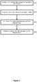
Figure 3 is a flow diagram illustrating an embodiment of a method of the present invention. - A first embodiment of a
computing system 100 of the present invention will now be described with reference toFigure 1 . Thecomputing system 100 includes atransceiver 101, aprocessor 103,memory 105, all connected via bus 107. Thecomputing system 100 is configured to generate data and/or receive data (via the transceiver 101), which may be stored inmemory 105 and processed byprocessor 103. In this embodiment, thecomputing system 100 is a Network Management System (NMS), which is part of a network as shown inFigure 2 . -
Figure 2 illustrates theNMS 100 and a plurality ofrouters 10A...10J, wherein the routers are interconnected by a bi-directional link (e.g. optical fibre) as illustrated. The NMS 100 is able to retrieve data from the routers (which is received at thetransceiver 101 and stored in memory 105). - The NMS 100 is configured to receive log data from the
routers 10A...10J indicating the routes traversed by packets through the network and whether or not a particular route was successful or not. An example of this log data is illustrated in the table, below.Data Session ID Data Packet ID Transmission Attempt Source Router 1st Int. Router 2nd Int. Router 3rd Int. Router ... Destination Router Success? ds1 dp1 1 10A 10C 10F N/A ... 10H Success ds1 dp2 1 10A 10C N/A N/A ... N/A Failure ds1 dp2 2 10A 10E 10F N/A ... 10H Success ds1 dp3 1 10A 10C N/A N/A ... N/A Failure ds1 dp3 2 10A 10B 10E 10F ... 10H Success ... ... ... ... ... ... ... ... ... ... - The following is noted regarding the log data:
- the data session ID and the data packet ID uniquely identify the data packet being transmitted, and the transmission count identifies how many transmission instances of that data packet have occurred (i.e. a value greater than one indicates a retransmission);
- The "Source router" data column identifies the router that transmitted the particular data packet;
- The "Destination Router" data column identifies the router that was the target destination of that data packet, or "N/A" if the packet never reached its destination;
- The "nth Intermediate Router" columns identifies one or more routers traversed by the packet in between the source and destination routers; and
- The "Success?" data column identifies whether the data packet reached the destination router.
- Within this log data example there is a
first network path 10A -> 10C -> 10F -> 10H (for packet ds1/dp1/1) and asecond network path 10A -> 10E -> 10F -> 10H (for packet ds1/dp2/2).Routers routers third network path 10A -> 10B -> 10E -> 10F -> 10H (for packet ds1/dp3/2).Routers 10C and the combination of 10B + 10E are "combination alternative routers" in the context of this invention as the routers immediately preceding and succeedingrouters 10C and the combination of 10B + 10E are the same, such thatrouters 10B + 10E may be used as an alternative path shouldrouter 10C fail (and vice versa). - Using these concepts, an example of the dynamic sequence alignment technique will now be illustrated, with reference to
Figure 3 , to evaluate the similarity between the first and second network path (that is, between 10A -> 10C -> 10F -> 10H and 10A-> 10E - > 10F -> 10H). A first step, step S1, is to construct a substitution matrix from the log data. A basic substitution matrix takes the following form:
- In this basic substitution matrix, the value of each matrix element, s, is:

- Thus, the basic substitution matrix is an identity matrix in which matching routers have value 1 and non-matching routers have value 0.
- Although the basic substitution matrix above may be used, in this embodiment a complex substitution matrix is used in which the elements off the main diagonal (i.e. for non-matching routers) can be non-zero. In the field of bioinformatics, these non-zero values are calculated based on the likelihood and frequency of mutation between two amino acids. In the present invention, these non-zero values for a matrix element represent the likelihood and frequency of two routers being used interchangeably in the log data, and are calculated using equation (2) below:
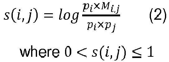
- In equation 2, s is the value for the matrix element, pi and pj are the frequencies of routers i and j in the log data and Mij is the count of times router j is used as an alternative router to router i.
- The complex substitution matrix may then be constructed as:

- In step S2 of this embodiment, the
NMS 100 then constructs a "score matrix" between the first and second network path. The matrix elements, hij , are constructed based on the following equations:


- i represents a router of the first network path and takes a value in the range {1, ..., len 1}, in which len1 represents the length of the first network path (i.e. the number of "hops"),
- j represents a router of the second network path from the log data and takes a value in the range {1, ..., len 2}, in which len2 represents the length of the second network path (i.e. the number of "hops"),
- h i0 and h 0j are calculated using equations (3) and (4) above and are initial values needed for the recursive formula in order to compute values for the elements hij of the score matrix,
- δ is a predetermined gap penalty value used to lower the score matrix element value when the two sequences have a gap in their alignment (e.g. a first and last subset of the routers match, but a middle subset of routers do not). The gap penalty value (also known as an insertion/deletion penalty value in bioinformatics) may be set by the Network Operator by calibration (e.g. using a test set of data), such that h i0, h 0j , h i-1,j - δ and h i,j-1 - δ are not under or overly penalised in the determination of hij ,
- xi and yj are the routers at positions i and j from the first and second network paths respectively, and
- s(xi ,yj ) is the value from the substitution matrix corresponding to events xi and yj .
- Before continuing with the remaining steps of the embodiment of the invention, the prior steps will be applied to the present example in which the similarity between the first network path (10A -> 10C -> 10F -> 10H) and the second network path (10A -> 10E -> 10F -> 10H) is being evaluated.
- First, a complex substitution matrix is constructed, in which sc,e is calculated - using the log data and equation (2) - to be 0.5:

- Next, the first network path is evaluated against the second network path by constructing a score matrix. The score matrix for this evaluation is:

- The matrix elements, hi,j , are computed using equations (3), (4) and (5) above, using a penalty parameter δ = 2:


- Once all matrix elements, hi,j , are calculated, the score matrix is:

- The next step of this technique is to create a trace-back matrix (step S3). The trace back matrix plots a path through the matrix from the bottom-right matrix element to the top-left matrix element. The trace-back matrix takes the same form as the score matrix (that is, the rows and columns of the matrix match the identities of the router sequences being evaluated), and the matrix elements are calculated as:

- Using the values of the score matrix and substitution matrix in the present example, the trace-back matrix is:

- Starting from the bottom-right matrix element q(4,4), the optimal path through the trace-back matrix is q(4,4) -> q(3,3) -> q(2,2) -> q(1,1).
- In the next step of this technique (step S4), the
NMS 100 calculates a value of similarity between the first and second network paths as the sum of values from the score matrix corresponding to the optimal path through the trace-back matrix. Using the trace-back matrix and score matrix above, this value is 3.5 + 2.5 + 1.5 + 1 = 8.5. - In this embodiment, the
NMS 100 is also able to evaluate the similarity between the first network path (10A -> 10C -> 10F -> 10H) and the third network path (1 0A -> 10B -> 10E -> 10F -> 10H). As noted above,routers 10B + 10E are "combination alternative routers" torouter 10C. However, as there are a differing number of routers insub-sequence 10B+10E of the third network path compared tosub-sequence 10B of the first network path, the dynamic sequence alignment technique must be modified. This will now be described. - The
NMS 100 compiles a modified log data table in which the combination alternative routers are replaced with a single ID. In this case, combinationalternative routers 10B + 10E are given ID B1. The modified log data table in this example is,Data Session ID Data Packet ID Transmission Attempt Source Router 1st Int. Router 2nd Int. Router 3rd Int. Router ... Destination Router Success? ds1 dp1 1 10A 10C 10F N/A ... 10H Success ds1 dp2 1 10A 10C N/A N/A ... N/A Failure ds1 dp2 2 10A 10E 10F N/A ... 10H Success ds1 dp3 1 10A 10C N/A N/A ... N/A Failure ds1 dp3 2 10A 10B1 10F ... ... 10H Success ... ... ... ... ... ... ... ... ... ... - A substitution matrix may now be created in which the single alternative routers and combination alternative routers are identified and evaluated. Accordingly, a complex substitution matrix may be compiled in which the values of each matrix element represent the likelihood of an alternative router (or combination alternative routers) are used instead of another router in the log data, and are again calculated based on equation (2),

router 10C may be used to calculate MC,B1 . - The complex substitution matrix may then be constructed as,

- In this example, the evaluated substitution matrix is:

- The
NMS 100 then creates a score matrix between the first and third network path, which is now possible as the combinationalternative routers 10B + 10E of third network path have been given a single ID, B1:
- The matrix elements, hi,j , are computed using equations (3), (4) and (5) above, using a penalty parameter δ = 2:


- The score matrix and trace-back matrix can therefore be created, and a value of similarity may therefore be determined, for the first and third network paths.
- In a further enhancement to this method, one or more "variants" of paths through the network are evaluated. This is achieved in the following manner. First, the log data for the network is analysed to determine a plurality of alternative routers and combination alternative routers. In the example data above, it was shown that
router 10E and combinationalternative routers 10B + 10E are alternative routers and combination alternative routers forrouter 10C. A mapping table is then created which identifies original routers and their alternative/combination alternative routers. For the purposes of this example, we shall assume that the log data includes further data (than identified in the example above) to create the following mapping table:ID Original Router Alternative Router(s) 1 10C 10E 2 10C 10B, 10E 3 10C 10K, 10L - Routers 10K and 10L are not shown in
Figure 1 , but in this example represent an alternative path for packets instead ofrouter 10C. - Based on this mapping table, the
NMS 100 is able to create a variant of the first network path (10A -> 10C -> 10F -> 10H), by reviewing the mapping table to determine that routers 10K + 10L are combination alternative routers that can be used instead ofrouter 10C, such that 10A -> 10K -> 10L -> 10F -> 10H is a variant of the first network path. TheNMS 100 may also determine whether the variant of the proposed path is a viable path (e.g. by checking that communication paths exist between 10A and 10K and between 10L and 10F) before continuing with the following process. - Following the method detailed above, the
NMS 100 is able to create a substitution matrix, score matrix and trace-back matrix for not only the first network path, but also the variant of the first network path, to determine a value of similarity with another (e.g. the second or third) network path. The value of similarity may then be some function of the evaluated value of similarity based on the first network path and the evaluated value of similarity based on the variant of the first network path. TheNMS 100 may also apply weightings to this function such that the influence of the variant(s) is less than that of the first network path. - A second embodiment of an NMS will now be described. The
NMS 100 is substantially similar to that of the first embodiment, and the same reference numerals will be used. In this embodiment, theNMS 100 is configured to receive data including an identifier for a website accessed by a user (e.g. a URL) and a timestamp indicating the date and time of access. TheNMS 100 may then store this log data inmemory 105, which may then be ordered (by the timestamp) to identify a sequence of websites accessed by a user in a particular session. An example of this log data is shown in the following table:ID Sequence of Websites 1 P1, P2, P3, P4 2 P1, P5, P3, P4 3 P1, P7, P8, P3, P4 - In this embodiment, the
NMS 100 is configured to use a Markov model to predict the next website to be accessed by a user. This is useful as the user may begin downloading data for the predicted next website before the user instructs the computing system to access it, which will reduce the time to load the website as the data is already locally available. The Markov model uses a transition matrix of the following form to predict the next website: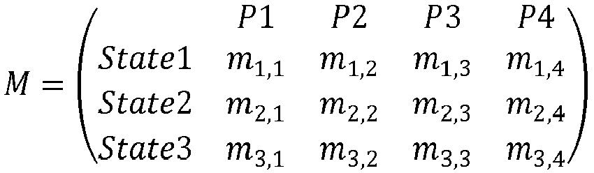
- The
NMS 100 prediction for the next webpage is based on its state, i (based on the user's immediately preceding accessed webpage(s)) and the probabilities for that state. For example, a 3rd order Markov model transition matrix may be created based on historical data to identify three states: State1=P1, P3, P4; State2=P2, P3, P5; and State3=P3, P4, P5. If the user's recently accessed websites are P4, P2, P3 and P5, then theNMS 100 may determine that the most recent 3 webpages are P2, P3 and P5, which corresponds to State2 of the transition matrix. TheNMS 100 then determines which webpage of P1 to P4 has the highest probability for State2 (i.e. max(m2,1 , m2,2, m2,3, m2,4 )), and this is the predicted next webpage for that user. - In this embodiment, the
NMS 100 is also able to predict the next website based on the user's previous webpages, even if those previous webpages do not correspond to a state in the transition matrix. For example, if the user has previously accessed webpages P1, P2, P4 and P5, then the previous three webpages (P2, P4 and P5) do not correspond to any of States 1 to 3 of the transition matrix. TheNMS 100 then predicts a next website for the user using the following method. - First, the
NMS 100 analyses the log data to identify instances in which a website has been used as an alternative website for another website (e.g. P5 instead of P2 in log data entries 1 and 2) or when a combination of websites have been used an alternative websites for another website (e.g. P7 and P8 instead of P2 in log data entries 1 and 3). TheNMS 100 then produces a modified log data table in which the combination alternative websites are explicitly identified with a unique ID:ID Sequence of Websites 1 P1, P2, P3, P4 2 P1, P5, P3, P4 3 P1, P7, P8, P3, P4 4 P1, P2-1, P3, P4 - The NMS 100 then constructs a substitution matrix based on the modified log data:

- As in the first embodiment, the values for si,j are evaluating the following equation using the log data:

- in which s is the value for the matrix element, pi and pj are the frequencies of websites i and j in the log data and Mij is the count of times website j is used as an alternative website to website i. As in the first embodiment, i and j may also represent combination alternative websites, such that pi and pj may represent the count of combination P7 and P8 in the log data and Mi,j may represent the count of combination P7 and P8 being used as alternative websites to P2. In this example, the substitution matrix is evaluated to be:

- In the next step, the
NMS 100 evaluates a score matrix between the previous three websites (P2, P4 and P5) and each of the three states of the current Markov transition matrix. The score matrix between the previous three websites and State1 is:
- As in the first embodiment, these values may be computed using equations (3), (4) and (5) and a penalty parameter δ=1:


- Once all values are evaluated, the matrix is:

- Using the local sequence alignment technique, the evaluated similarity between the previously access websites and the first state is therefore 0.5.
- The
NMS 100 then repeats this process for each state, which returns similarity scores of 2 for State 2 and 2.5 for State 3. Accordingly, the most similar state to the previously accessed websites is State 3. Based on this determination, theNMS 100 creates a new entry in the Markov transition matrix, State4, corresponding to website sequence P2, P4 and P5, which uses the same probability values for websites P1, P2, P3 and P4 as used for State 3:
- The skilled person will understand that it is possible to create a variant of the three previously accessed websites using the log data in the same manner as the first embodiment. For example, website sequence P2, P4 and P5 may have a variant P2-1, P4 and P5. The similarity between the three previously accessed websites, and their variants, with the Markov transition matrix states may therefore be evaluated in order to determine the most similar state.
- The skilled person will understand that the sequence processing techniques described in the first and second embodiments are examples only and the concepts of the present invention may be applied in many other ways. In particular, the second embodiment is not limited to the use of 3rd order Markov models, as any order may be used, and the sequence alignment technique may be global or local alignment in either embodiment.
- Furthermore, the skilled person will understand that the above method of the present invention may be performed by any computing device, and not just the NMS of the examples above. The method may also be performed locally (that is, at the node collecting the relevant data), or by another entity (configured to receive the relevant data).
- The skilled person will also understand that the method of the present invention may be applied to sequences within any data set. Data sets may be recorded or received in discrete amounts (thus defining a start and end to the sequence) or via a continuous stream, but the method may also define starts and ends to sequences in other ways, such as logical starts and end points based on the data set or by using a sliding window to separate the data set into sequences of defined length.
- The skilled person will understand that any combination of features is possible within the scope of the invention, as claimed.
Claims (14)
- A method of processing a sequence in a computing system, the method comprising the steps of:a) receiving data of a plurality of historical sequences in a computing system, wherein the data for each historical sequence identifies each point in the historical sequence;b) analysing the historical data to identify a first and second alternative sub-sequence within a first and second historical sequence, wherein the first alternative sub-sequence includes a first common point identified in both the first and second historical sequence, a first intermediate point identified in the first historical sequence, and a second common point identified in both the first and second historical sequences, and the second alternative sub-sequence includes the first common point, a plurality of intermediate points identified in the second historical sequence, and the second common point;c) defining a virtual point as the plurality of intermediate points and a virtual sub-sequence as the first common point followed by the virtual point followed by the second common point;d) processing a first sequence in the computing system by:i) identifying the second alternative sub-sequence in the first sequence; andii) defining a first variant sequence as the first sequence with the second alternative sub-sequence replaced with the virtual sub-sequence.
- A method as claimed in Claim 1, wherein the data further includes a property of each of the plurality of historical sequences, and the method further comprises the steps of:e) predicting a property of the first sequence in the computing system byi) calculating a value of similarity between the first variant sequence and each of the plurality of historical sequences; andii) predicting the property of the first sequence based on the calculated values of similarity.
- A method as claimed in Claim 1, wherein the first sequence in the computing system is the second historical sequence of the plurality of historical sequences.
- A method as claimed in Claim 3, wherein the data further includes a property of each of the plurality of historical sequences, and the method further comprises the steps of:e) predicting a property of a second sequence in the computing system byi) calculating a value of similarity between the second sequence and each the plurality of historical sequences; andii) predicting the property for the second sequence based on the calculated values of similarity.
- A method as claimed in Claim 4, wherein step e) of predicting the property of the second sequence in the computing system includes:i.i) identifying the second alternative sub-sequence in the second sequence;i.ii) defining a second variant sequence as the second sequence with the second alternative sub-sequence replaced with the virtual sub-sequence;i.iii) calculating the value of similarity between the second variant sequence and each of the plurality of historical sequences; andii) predicting the property for the second sequence based on the calculated values of similarity.
- A method as claimed in Claim 1, wherein the first variant sequence is a state in a Markov model transition matrix.
- A computer program product comprising instructions which, when the program is executed by a computer, causes the computer to carry out the steps of the method of any one of the preceding claims.
- A device for processing a sequence in a computing system, the device comprising
a transceiver adapted to receive data of a plurality of historical sequences in a computing system, wherein the data for each historical sequence identifies each point in the historical sequence; and
a processor adapted to:analyse the historical data to identify a first and second alternative sub-sequence within a first and second historical sequence, wherein the first alternative sub-sequence includes a first common point identified in both the first and second historical sequence, a first intermediate point identified in the first historical sequence, and a second common point identified in both the first and second historical sequences, and the second alternative sub-sequence includes the first common point, a plurality of intermediate points identified in the second historical sequence, and the second common point;define a virtual point as the plurality of intermediate points and a virtual sub-sequence as the first common point followed by the virtual point followed by the second common point; andprocess a first sequence in the computing system by:identifying the second alternative sub-sequence in the first sequence; anddefining a first variant sequence as the first sequence with the second alternative sub-sequence replaced with the virtual sub-sequence. - A device as claimed in Claim 8, wherein the data further includes a property of each of the plurality of historical sequences, and the processor is further adapted to:predict a property of the first sequence in the computing system bycalculating a value of similarity between the first variant sequence and each of the plurality of historical sequences; andpredicting the property of the first sequence based on the calculated values of similarity.
- A device as claimed in Claim 8, wherein the first sequence in the computing system is the second historical sequence of the plurality of historical sequences.
- A device as claimed in Claim 10, wherein the data further includes a property of each of the plurality of historical sequences, and the processor is further adapted to:predict a property of a second sequence in the computing system bycalculating a value of similarity between the second sequence and each the plurality of historical sequences; andpredicting the property for the second sequence based on the calculated values of similarity.
- A device as claimed in Claim 11, wherein the processor step of predicting the property of the second sequence in the computing system includes:identifying the second alternative sub-sequence in the second sequence;defining a second variant sequence as the second sequence with the second alternative sub-sequence replaced with the virtual sub-sequence;calculating the value of similarity between the second variant sequence and each of the plurality of historical sequences; andpredicting the property for the second sequence based on the calculated values of similarity.
- A device as claimed in Claim 8, wherein the first variant sequence is a state in a Markov model transition matrix.
- A device as claimed in any one of Claims 8 to 13, being a Network Management System.
Applications Claiming Priority (2)
| Application Number | Priority Date | Filing Date | Title |
|---|---|---|---|
| EP16184347 | 2016-08-16 | ||
| EP17154527 | 2017-02-03 |
Publications (2)
| Publication Number | Publication Date |
|---|---|
| EP3285442A1 true EP3285442A1 (en) | 2018-02-21 |
| EP3285442B1 EP3285442B1 (en) | 2020-03-25 |
Family
ID=56694017
Family Applications (1)
| Application Number | Title | Priority Date | Filing Date |
|---|---|---|---|
| EP17186310.3A Active EP3285442B1 (en) | 2016-08-16 | 2017-08-15 | A method of processing a sequence in a computing system |
Country Status (1)
| Country | Link |
|---|---|
| EP (1) | EP3285442B1 (en) |
Cited By (1)
| Publication number | Priority date | Publication date | Assignee | Title |
|---|---|---|---|---|
| CN108536776A (en) * | 2018-03-28 | 2018-09-14 | 广州厚云信息科技有限公司 | Unification user malicious act detection method and system in a kind of social networks |
Citations (1)
| Publication number | Priority date | Publication date | Assignee | Title |
|---|---|---|---|---|
| US6665271B1 (en) * | 1998-03-17 | 2003-12-16 | Transnexus, Llc | System for real-time prediction of quality for internet-based multimedia communications |
-
2017
- 2017-08-15 EP EP17186310.3A patent/EP3285442B1/en active Active
Patent Citations (1)
| Publication number | Priority date | Publication date | Assignee | Title |
|---|---|---|---|---|
| US6665271B1 (en) * | 1998-03-17 | 2003-12-16 | Transnexus, Llc | System for real-time prediction of quality for internet-based multimedia communications |
Non-Patent Citations (1)
| Title |
|---|
| KRUSKAL J B ET AL: "AN ANTHOLOGY OF ALGORITHMS AND CONCEPTS FOR SEQUENCE COMPARISON", TIME WARPS, STRING EDITS AND MACROMOLECULES : THE THEORY ANDPRACTICE OF SEQUENCE COMPARISON, ADDISON-WESLEY PUBLISHING CO., AMSTERDAM, NL, 1 January 1983 (1983-01-01), pages 265 - 310, XP000570580 * |
Cited By (1)
| Publication number | Priority date | Publication date | Assignee | Title |
|---|---|---|---|---|
| CN108536776A (en) * | 2018-03-28 | 2018-09-14 | 广州厚云信息科技有限公司 | Unification user malicious act detection method and system in a kind of social networks |
Also Published As
| Publication number | Publication date |
|---|---|
| EP3285442B1 (en) | 2020-03-25 |
Similar Documents
| Publication | Publication Date | Title |
|---|---|---|
| Ahmed et al. | Multivariate online anomaly detection using kernel recursive least squares | |
| EP2680636B1 (en) | Reporting method, detection method, device and system for network state | |
| Hassine et al. | ARMA based popularity prediction for caching in content delivery networks | |
| EP3163519A1 (en) | Methods for detecting one or more aircraft anomalies and devices thereof | |
| US20100329120A1 (en) | Determining Disjoint Paths With An Optimized Number Of Regenerators | |
| US20080036630A1 (en) | Apparatus and methods for searching a pattern in a compressed data | |
| CN111275350B (en) | Method and device for updating event evaluation model | |
| Chen et al. | Session-based recommendation with local invariance | |
| US11461590B2 (en) | Train a machine learning model using IP addresses and connection contexts | |
| US20140280929A1 (en) | Multi-tier message correlation | |
| CN117499147B (en) | Multi-protocol-adaptive remote connection security management method and system | |
| EP3285442B1 (en) | A method of processing a sequence in a computing system | |
| WO2020227985A1 (en) | Real-time fault detection on network devices and circuits based on traffic volume statistics | |
| US20130250805A1 (en) | Method for investigating a data transport network and computer program product | |
| EP3493063A1 (en) | A monitoring system and method | |
| Kempa | On main characteristics of the $ M/M/1/N $ queue with single and batch arrivals and the queue size controlled by AQM algorithms | |
| CN113076324A (en) | Method and device for determining database and table dividing strategies | |
| CN115860856B (en) | A data processing method, apparatus, electronic device, and storage medium | |
| Villaça et al. | Online learning under resource constraints | |
| Lin et al. | DT-track: Using DNS-timing side channel for mobile user tracking | |
| Luo et al. | Optimal (r, N)‐policy for discrete‐time Geo∕ G∕ 1 queue with different input rate and setup time | |
| JP7396469B2 (en) | Traffic monitoring devices, methods and programs | |
| CN116090021A (en) | Authentication method and device of access equipment and communication equipment | |
| CN115904796B (en) | Encoding and decoding method, system and readable storage medium for long-chain erasure codes | |
| CN116248527B (en) | Application service evaluation methods, devices and electronic equipment |
Legal Events
| Date | Code | Title | Description |
|---|---|---|---|
| PUAI | Public reference made under article 153(3) epc to a published international application that has entered the european phase |
Free format text: ORIGINAL CODE: 0009012 |
|
| STAA | Information on the status of an ep patent application or granted ep patent |
Free format text: STATUS: THE APPLICATION HAS BEEN PUBLISHED |
|
| AK | Designated contracting states |
Kind code of ref document: A1 Designated state(s): AL AT BE BG CH CY CZ DE DK EE ES FI FR GB GR HR HU IE IS IT LI LT LU LV MC MK MT NL NO PL PT RO RS SE SI SK SM TR |
|
| AX | Request for extension of the european patent |
Extension state: BA ME |
|
| STAA | Information on the status of an ep patent application or granted ep patent |
Free format text: STATUS: REQUEST FOR EXAMINATION WAS MADE |
|
| 17P | Request for examination filed |
Effective date: 20180807 |
|
| RBV | Designated contracting states (corrected) |
Designated state(s): AL AT BE BG CH CY CZ DE DK EE ES FI FR GB GR HR HU IE IS IT LI LT LU LV MC MK MT NL NO PL PT RO RS SE SI SK SM TR |
|
| STAA | Information on the status of an ep patent application or granted ep patent |
Free format text: STATUS: EXAMINATION IS IN PROGRESS |
|
| 17Q | First examination report despatched |
Effective date: 20181002 |
|
| RIC1 | Information provided on ipc code assigned before grant |
Ipc: H04L 12/721 20130101AFI20190917BHEP Ipc: H04L 12/707 20130101ALI20190917BHEP |
|
| GRAP | Despatch of communication of intention to grant a patent |
Free format text: ORIGINAL CODE: EPIDOSNIGR1 |
|
| STAA | Information on the status of an ep patent application or granted ep patent |
Free format text: STATUS: GRANT OF PATENT IS INTENDED |
|
| INTG | Intention to grant announced |
Effective date: 20191104 |
|
| GRAS | Grant fee paid |
Free format text: ORIGINAL CODE: EPIDOSNIGR3 |
|
| GRAA | (expected) grant |
Free format text: ORIGINAL CODE: 0009210 |
|
| STAA | Information on the status of an ep patent application or granted ep patent |
Free format text: STATUS: THE PATENT HAS BEEN GRANTED |
|
| AK | Designated contracting states |
Kind code of ref document: B1 Designated state(s): AL AT BE BG CH CY CZ DE DK EE ES FI FR GB GR HR HU IE IS IT LI LT LU LV MC MK MT NL NO PL PT RO RS SE SI SK SM TR |
|
| REG | Reference to a national code |
Ref country code: GB Ref legal event code: FG4D |
|
| REG | Reference to a national code |
Ref country code: AT Ref legal event code: REF Ref document number: 1249863 Country of ref document: AT Kind code of ref document: T Effective date: 20200415 Ref country code: IE Ref legal event code: FG4D |
|
| REG | Reference to a national code |
Ref country code: DE Ref legal event code: R096 Ref document number: 602017013508 Country of ref document: DE |
|
| PG25 | Lapsed in a contracting state [announced via postgrant information from national office to epo] |
Ref country code: NO Free format text: LAPSE BECAUSE OF FAILURE TO SUBMIT A TRANSLATION OF THE DESCRIPTION OR TO PAY THE FEE WITHIN THE PRESCRIBED TIME-LIMIT Effective date: 20200625 Ref country code: FI Free format text: LAPSE BECAUSE OF FAILURE TO SUBMIT A TRANSLATION OF THE DESCRIPTION OR TO PAY THE FEE WITHIN THE PRESCRIBED TIME-LIMIT Effective date: 20200325 Ref country code: RS Free format text: LAPSE BECAUSE OF FAILURE TO SUBMIT A TRANSLATION OF THE DESCRIPTION OR TO PAY THE FEE WITHIN THE PRESCRIBED TIME-LIMIT Effective date: 20200325 |
|
| PG25 | Lapsed in a contracting state [announced via postgrant information from national office to epo] |
Ref country code: HR Free format text: LAPSE BECAUSE OF FAILURE TO SUBMIT A TRANSLATION OF THE DESCRIPTION OR TO PAY THE FEE WITHIN THE PRESCRIBED TIME-LIMIT Effective date: 20200325 Ref country code: SE Free format text: LAPSE BECAUSE OF FAILURE TO SUBMIT A TRANSLATION OF THE DESCRIPTION OR TO PAY THE FEE WITHIN THE PRESCRIBED TIME-LIMIT Effective date: 20200325 Ref country code: LV Free format text: LAPSE BECAUSE OF FAILURE TO SUBMIT A TRANSLATION OF THE DESCRIPTION OR TO PAY THE FEE WITHIN THE PRESCRIBED TIME-LIMIT Effective date: 20200325 Ref country code: BG Free format text: LAPSE BECAUSE OF FAILURE TO SUBMIT A TRANSLATION OF THE DESCRIPTION OR TO PAY THE FEE WITHIN THE PRESCRIBED TIME-LIMIT Effective date: 20200625 Ref country code: GR Free format text: LAPSE BECAUSE OF FAILURE TO SUBMIT A TRANSLATION OF THE DESCRIPTION OR TO PAY THE FEE WITHIN THE PRESCRIBED TIME-LIMIT Effective date: 20200626 |
|
| REG | Reference to a national code |
Ref country code: NL Ref legal event code: MP Effective date: 20200325 |
|
| REG | Reference to a national code |
Ref country code: LT Ref legal event code: MG4D |
|
| PG25 | Lapsed in a contracting state [announced via postgrant information from national office to epo] |
Ref country code: NL Free format text: LAPSE BECAUSE OF FAILURE TO SUBMIT A TRANSLATION OF THE DESCRIPTION OR TO PAY THE FEE WITHIN THE PRESCRIBED TIME-LIMIT Effective date: 20200325 |
|
| PG25 | Lapsed in a contracting state [announced via postgrant information from national office to epo] |
Ref country code: IS Free format text: LAPSE BECAUSE OF FAILURE TO SUBMIT A TRANSLATION OF THE DESCRIPTION OR TO PAY THE FEE WITHIN THE PRESCRIBED TIME-LIMIT Effective date: 20200725 Ref country code: CZ Free format text: LAPSE BECAUSE OF FAILURE TO SUBMIT A TRANSLATION OF THE DESCRIPTION OR TO PAY THE FEE WITHIN THE PRESCRIBED TIME-LIMIT Effective date: 20200325 Ref country code: SK Free format text: LAPSE BECAUSE OF FAILURE TO SUBMIT A TRANSLATION OF THE DESCRIPTION OR TO PAY THE FEE WITHIN THE PRESCRIBED TIME-LIMIT Effective date: 20200325 Ref country code: PT Free format text: LAPSE BECAUSE OF FAILURE TO SUBMIT A TRANSLATION OF THE DESCRIPTION OR TO PAY THE FEE WITHIN THE PRESCRIBED TIME-LIMIT Effective date: 20200818 Ref country code: EE Free format text: LAPSE BECAUSE OF FAILURE TO SUBMIT A TRANSLATION OF THE DESCRIPTION OR TO PAY THE FEE WITHIN THE PRESCRIBED TIME-LIMIT Effective date: 20200325 Ref country code: SM Free format text: LAPSE BECAUSE OF FAILURE TO SUBMIT A TRANSLATION OF THE DESCRIPTION OR TO PAY THE FEE WITHIN THE PRESCRIBED TIME-LIMIT Effective date: 20200325 Ref country code: LT Free format text: LAPSE BECAUSE OF FAILURE TO SUBMIT A TRANSLATION OF THE DESCRIPTION OR TO PAY THE FEE WITHIN THE PRESCRIBED TIME-LIMIT Effective date: 20200325 Ref country code: RO Free format text: LAPSE BECAUSE OF FAILURE TO SUBMIT A TRANSLATION OF THE DESCRIPTION OR TO PAY THE FEE WITHIN THE PRESCRIBED TIME-LIMIT Effective date: 20200325 |
|
| REG | Reference to a national code |
Ref country code: AT Ref legal event code: MK05 Ref document number: 1249863 Country of ref document: AT Kind code of ref document: T Effective date: 20200325 |
|
| REG | Reference to a national code |
Ref country code: DE Ref legal event code: R097 Ref document number: 602017013508 Country of ref document: DE |
|
| PG25 | Lapsed in a contracting state [announced via postgrant information from national office to epo] |
Ref country code: AT Free format text: LAPSE BECAUSE OF FAILURE TO SUBMIT A TRANSLATION OF THE DESCRIPTION OR TO PAY THE FEE WITHIN THE PRESCRIBED TIME-LIMIT Effective date: 20200325 Ref country code: DK Free format text: LAPSE BECAUSE OF FAILURE TO SUBMIT A TRANSLATION OF THE DESCRIPTION OR TO PAY THE FEE WITHIN THE PRESCRIBED TIME-LIMIT Effective date: 20200325 Ref country code: IT Free format text: LAPSE BECAUSE OF FAILURE TO SUBMIT A TRANSLATION OF THE DESCRIPTION OR TO PAY THE FEE WITHIN THE PRESCRIBED TIME-LIMIT Effective date: 20200325 Ref country code: ES Free format text: LAPSE BECAUSE OF FAILURE TO SUBMIT A TRANSLATION OF THE DESCRIPTION OR TO PAY THE FEE WITHIN THE PRESCRIBED TIME-LIMIT Effective date: 20200325 |
|
| PLBE | No opposition filed within time limit |
Free format text: ORIGINAL CODE: 0009261 |
|
| STAA | Information on the status of an ep patent application or granted ep patent |
Free format text: STATUS: NO OPPOSITION FILED WITHIN TIME LIMIT |
|
| PG25 | Lapsed in a contracting state [announced via postgrant information from national office to epo] |
Ref country code: PL Free format text: LAPSE BECAUSE OF FAILURE TO SUBMIT A TRANSLATION OF THE DESCRIPTION OR TO PAY THE FEE WITHIN THE PRESCRIBED TIME-LIMIT Effective date: 20200325 |
|
| REG | Reference to a national code |
Ref country code: DE Ref legal event code: R119 Ref document number: 602017013508 Country of ref document: DE |
|
| 26N | No opposition filed |
Effective date: 20210112 |
|
| PG25 | Lapsed in a contracting state [announced via postgrant information from national office to epo] |
Ref country code: MC Free format text: LAPSE BECAUSE OF FAILURE TO SUBMIT A TRANSLATION OF THE DESCRIPTION OR TO PAY THE FEE WITHIN THE PRESCRIBED TIME-LIMIT Effective date: 20200325 |
|
| REG | Reference to a national code |
Ref country code: CH Ref legal event code: PL |
|
| PG25 | Lapsed in a contracting state [announced via postgrant information from national office to epo] |
Ref country code: CH Free format text: LAPSE BECAUSE OF NON-PAYMENT OF DUE FEES Effective date: 20200831 Ref country code: LI Free format text: LAPSE BECAUSE OF NON-PAYMENT OF DUE FEES Effective date: 20200831 Ref country code: LU Free format text: LAPSE BECAUSE OF NON-PAYMENT OF DUE FEES Effective date: 20200815 |
|
| REG | Reference to a national code |
Ref country code: BE Ref legal event code: MM Effective date: 20200831 |
|
| PG25 | Lapsed in a contracting state [announced via postgrant information from national office to epo] |
Ref country code: SI Free format text: LAPSE BECAUSE OF FAILURE TO SUBMIT A TRANSLATION OF THE DESCRIPTION OR TO PAY THE FEE WITHIN THE PRESCRIBED TIME-LIMIT Effective date: 20200325 |
|
| PG25 | Lapsed in a contracting state [announced via postgrant information from national office to epo] |
Ref country code: FR Free format text: LAPSE BECAUSE OF NON-PAYMENT OF DUE FEES Effective date: 20200831 Ref country code: DE Free format text: LAPSE BECAUSE OF NON-PAYMENT OF DUE FEES Effective date: 20210302 |
|
| PG25 | Lapsed in a contracting state [announced via postgrant information from national office to epo] |
Ref country code: IE Free format text: LAPSE BECAUSE OF NON-PAYMENT OF DUE FEES Effective date: 20200815 Ref country code: BE Free format text: LAPSE BECAUSE OF NON-PAYMENT OF DUE FEES Effective date: 20200831 |
|
| PG25 | Lapsed in a contracting state [announced via postgrant information from national office to epo] |
Ref country code: TR Free format text: LAPSE BECAUSE OF FAILURE TO SUBMIT A TRANSLATION OF THE DESCRIPTION OR TO PAY THE FEE WITHIN THE PRESCRIBED TIME-LIMIT Effective date: 20200325 Ref country code: MT Free format text: LAPSE BECAUSE OF FAILURE TO SUBMIT A TRANSLATION OF THE DESCRIPTION OR TO PAY THE FEE WITHIN THE PRESCRIBED TIME-LIMIT Effective date: 20200325 Ref country code: CY Free format text: LAPSE BECAUSE OF FAILURE TO SUBMIT A TRANSLATION OF THE DESCRIPTION OR TO PAY THE FEE WITHIN THE PRESCRIBED TIME-LIMIT Effective date: 20200325 |
|
| PG25 | Lapsed in a contracting state [announced via postgrant information from national office to epo] |
Ref country code: MK Free format text: LAPSE BECAUSE OF FAILURE TO SUBMIT A TRANSLATION OF THE DESCRIPTION OR TO PAY THE FEE WITHIN THE PRESCRIBED TIME-LIMIT Effective date: 20200325 Ref country code: AL Free format text: LAPSE BECAUSE OF FAILURE TO SUBMIT A TRANSLATION OF THE DESCRIPTION OR TO PAY THE FEE WITHIN THE PRESCRIBED TIME-LIMIT Effective date: 20200325 |
|
| P01 | Opt-out of the competence of the unified patent court (upc) registered |
Effective date: 20230623 |
|
| PGFP | Annual fee paid to national office [announced via postgrant information from national office to epo] |
Ref country code: GB Payment date: 20250725 Year of fee payment: 9 |