EP3285245A1 - Performance-based track variation for aircraft flight management - Google Patents
Performance-based track variation for aircraft flight management Download PDFInfo
- Publication number
- EP3285245A1 EP3285245A1 EP17171895.0A EP17171895A EP3285245A1 EP 3285245 A1 EP3285245 A1 EP 3285245A1 EP 17171895 A EP17171895 A EP 17171895A EP 3285245 A1 EP3285245 A1 EP 3285245A1
- Authority
- EP
- European Patent Office
- Prior art keywords
- aircraft
- flight path
- flight
- rnp
- margin
- Prior art date
- Legal status (The legal status is an assumption and is not a legal conclusion. Google has not performed a legal analysis and makes no representation as to the accuracy of the status listed.)
- Granted
Links
Images



Classifications
-
- G—PHYSICS
- G08—SIGNALLING
- G08G—TRAFFIC CONTROL SYSTEMS
- G08G5/00—Traffic control systems for aircraft
- G08G5/30—Flight plan management
- G08G5/34—Flight plan management for flight plan modification
-
- G—PHYSICS
- G01—MEASURING; TESTING
- G01C—MEASURING DISTANCES, LEVELS OR BEARINGS; SURVEYING; NAVIGATION; GYROSCOPIC INSTRUMENTS; PHOTOGRAMMETRY OR VIDEOGRAMMETRY
- G01C21/00—Navigation; Navigational instruments not provided for in groups G01C1/00 - G01C19/00
- G01C21/20—Instruments for performing navigational calculations
-
- G—PHYSICS
- G08—SIGNALLING
- G08G—TRAFFIC CONTROL SYSTEMS
- G08G5/00—Traffic control systems for aircraft
- G08G5/20—Arrangements for acquiring, generating, sharing or displaying traffic information
- G08G5/21—Arrangements for acquiring, generating, sharing or displaying traffic information located onboard the aircraft
-
- G—PHYSICS
- G08—SIGNALLING
- G08G—TRAFFIC CONTROL SYSTEMS
- G08G5/00—Traffic control systems for aircraft
- G08G5/20—Arrangements for acquiring, generating, sharing or displaying traffic information
- G08G5/26—Transmission of traffic-related information between aircraft and ground stations
-
- G—PHYSICS
- G08—SIGNALLING
- G08G—TRAFFIC CONTROL SYSTEMS
- G08G5/00—Traffic control systems for aircraft
- G08G5/50—Navigation or guidance aids
-
- G—PHYSICS
- G08—SIGNALLING
- G08G—TRAFFIC CONTROL SYSTEMS
- G08G5/00—Traffic control systems for aircraft
- G08G5/50—Navigation or guidance aids
- G08G5/54—Navigation or guidance aids for approach or landing
-
- G—PHYSICS
- G08—SIGNALLING
- G08G—TRAFFIC CONTROL SYSTEMS
- G08G5/00—Traffic control systems for aircraft
- G08G5/50—Navigation or guidance aids
- G08G5/55—Navigation or guidance aids for a single aircraft
Definitions
- the present disclosure relates generally to methods for modifying a flight path of an aircraft, and more particularly to calculating, by a system onboard the aircraft, a modification to the flight path to be flown by the aircraft that causes the aircraft to remain within containment boundaries of a Required Navigation Performance (RNP) instrument flight procedure while reducing noise impact to the communities underneath the flight path and meeting the spacing requirements of the air traffic controller.
- RNP Required Navigation Performance
- Performance-Based Navigation including the widely used Required Navigation Performance (RNP) and Area Navigation (RNAV) instrument procedures, are key parts of airspace modernization worldwide.
- RNP Required Navigation Performance
- RNAV Area Navigation
- FAM Federal Aviation Administration
- RNAV and RNP-based procedure deployment is a component of the United States' airspace modernization, the Federal Aviation Administration (FAA) NextGen program, that is implementing new PBN routes and procedures to leverage emerging technologies and aircraft navigation capabilities.
- FAM Federal Aviation Administration
- Modem commercial aircraft fly PBN flight paths with very high precision.
- the aircraft can exploit high accuracy provided by global positioning system (GPS)-based navigation systems, modem Flight Management Systems (FMSs) and Flight Control Systems (FCSs). Due to this highly accurate path-keeping capability, the use of PBN removes much of the variability traditionally seen in aircraft flight paths, and results in highly repeatable operations.
- GPS global positioning system
- FMSs modem Flight Management Systems
- FCSs Flight Control Systems Due to this highly accurate path-keeping capability, the use of PBN removes
- RNAV and RNP procedures thus include improved aircraft stability on approach, improved aircraft predictability for air traffic control, reduced fuel burn, lower track miles, improved airport capacity, reduced (concentrated) noise footprints, and paths tailored to avoid noise sensitive areas.
- these same procedures can be detrimental for the exact reason that modem commercial aircraft fly RNAV and RNP defined flight paths with very high precision.
- a method for modifying a flight path of an aircraft comprises receiving real time positioning information for an aircraft, and receiving an actual navigation performance (ANP) of the aircraft.
- the ANP indicates uncertainty in the real time positioning of the aircraft based on information collected from a navigation system onboard the aircraft.
- the method also comprises receiving a required navigation performance (RNP) instrument flight procedure for the aircraft, and the RNP instrument flight procedure indicates a fixed-route accuracy and containment boundaries required during flight for the aircraft to fly a path between two points along a flight path.
- the containment boundaries are defined by a flight path centerline with limits determined by associated margins.
- the method also comprises receiving spacing input from an air traffic controller that indicates spacing requirements between the aircraft and one or more other aircraft, and receiving information relating to communities underneath the flight path.
- the method also comprises calculating, by a system onboard the aircraft, a modification to the flight path to be flown by the aircraft that causes the aircraft to remain within the containment boundaries of the RNP instrument flight procedure while reducing noise impact to the communities underneath the flight path and meeting the spacing requirements of the air traffic controller, and displaying a visual representation of a modified flight path for the aircraft.
- a system in another example, comprises a communication interface for receiving real time positioning of an aircraft during flight, and an actual navigation performance (ANP) of the aircraft.
- the ANP indicates uncertainty in the real time positioning of the aircraft.
- the communication interface also for receiving information for a required navigation performance (RNP) instrument flight procedure for the aircraft, and the RNP instrument flight procedure indicates a fixed-route accuracy and containment boundaries required during flight for the aircraft to fly a path between two points along a flight path.
- the containment boundaries are defined by a flight path centerline with limits determined by associated margins.
- the system also includes data storage for storing spacing input from an air traffic controller that indicates spacing requirements between the aircraft and one or more other aircraft, and information relating to communities underneath the flight path.
- the system also includes one or more processors for executing instructions stored on the data storage to calculate a modification to the flight path to be flown by the aircraft that causes the aircraft to remain within the containment boundaries of the RNP instrument flight procedure while reducing noise impact to the communities underneath the flight path and meeting the spacing requirements of the air traffic controller, and an output interface for outputting a modified flight path for the aircraft.
- a non-transitory computer readable storage medium having stored therein instructions, that when executed by a system having one or more processors, causes the system to perform functions.
- the functions comprise receiving real time positioning information of an aircraft, and receiving an actual navigation performance (ANP) of the aircraft.
- the ANP indicates uncertainty in the real time positioning of the aircraft based on information collected from a navigation system onboard the aircraft.
- the functions also comprise receiving a required navigation performance (RNP) instrument flight procedure, and the RNP indicates a fixed-route accuracy and containment boundaries required during flight for the aircraft to fly a path between two points along a flight path.
- the containment boundaries are defined by a flight path centerline with limits determined by associated margins.
- the functions also comprise receiving spacing input from an air traffic controller that indicates spacing requirements between the aircraft and one or more other aircraft, and receiving information relating to communities underneath the flight path.
- the functions also comprise calculating a modification to the flight path to be flown by the aircraft that causes the aircraft to remain within the containment boundaries of the RNP while reducing noise impact to the communities underneath the flight path and meeting the spacing requirements of the air traffic controller, and displaying a visual representation of a modified flight path for the aircraft.
- Described below are example systems and methods to implement variation in flight paths that can assist with spreading a noise footprint stemming from repeatable operations as well as reducing concentrated traffic patterns.
- An example method for modifying a flight path of an aircraft includes receiving real time positioning information for an aircraft, receiving a calculated actual navigation performance (ANP) of the aircraft, receiving a required navigation performance (RNP) instrument flight procedure for the aircraft, receiving spacing input from an air traffic controller that indicates spacing requirements between the aircraft and one or more other aircraft, receiving information relating to communities underneath the flight path, calculating, by a system onboard the aircraft, a modification to the flight path to be flown by the aircraft that causes the aircraft to remain within the containment boundaries of the RNP instrument flight procedure while reducing noise impact to the communities underneath the flight path and meeting the spacing requirements of the air traffic controller, and displaying a visual representation of a modified flight path for the aircraft.
- the aircraft 100 includes a system 102 onboard the aircraft 100 that is in communication with a navigation system 104 and a flight manager 105 onboard the aircraft 100.
- the system 102 includes a communication interface 106, data storage 108, one or more processor(s) 110, an output interface 112, and a display 114 each connected to a communication bus 116.
- the system 102 may also include hardware to enable communication within the system 102 and between the system 102 and other devices (not shown).
- the hardware may include transmitters, receivers, and antennas, for example.
- the communication interface 106 may be a wireless interface and/or one or more wireline interfaces that allow for both short-range communication and long-range communication to one or more networks or to one or more remote devices.
- Such wireless interfaces may provide for communication under one or more wireless communication protocols, such as voice communication using Very High Frequency (VHF), VHF Data link (VDL), VDL Mode 2, Aircraft Communications Addressing and Reporting System (ACARS) digital communications over VHF radio and satellite communications (SATCOM), Bluetooth, WiFi (e.g., an institute of electrical and electronic engineers (IEEE) 802.11 protocol), Long-Term Evolution (LTE), cellular communications, near-field communication (NFC), and/or other wireless communication protocols.
- VHF Very High Frequency
- VDL VHF Data link
- VDL Mode 2 Aircraft Communications Addressing and Reporting System
- SATCOM Aircraft Communications Addressing and Reporting System
- WiFi e.g., an institute of electrical and electronic engineers (IEEE) 802.11 protocol
- LTE Long-Term Evolution
- NFC near-
- Such wireline interfaces may include aircraft data buses such as Aeronautical Radio, Incorporated (ARINC) 429, 629, or 664 based interfaces, Ethernet interface, a Universal Serial Bus (USB) interface, or similar interface to communicate via a wire, a twisted pair of wires, a coaxial cable, an optical link, a fiber-optic link, or other physical connection to a wireline network.
- aircraft data buses such as Aeronautical Radio, Incorporated (ARINC) 429, 629, or 664 based interfaces, Ethernet interface, a Universal Serial Bus (USB) interface, or similar interface to communicate via a wire, a twisted pair of wires, a coaxial cable, an optical link, a fiber-optic link, or other physical connection to a wireline network.
- ARINC Aeronautical Radio, Incorporated
- 629 629
- 664 Ethernet interface
- USB Universal Serial Bus
- the communication interface 106 may be configured to receive input data from one or more devices, and may also be configured to send output data to other devices. In some examples, the communication interface 106 may also maintain and manage records of data received and sent by the system 102. The communication interface 106 may also include a receiver and transmitter to receive and send data. In other examples, the communication interface 106 may also include a user-interface, such as a keyboard, microphone, touchscreen, etc., to receive inputs as well.
- the communication interface 106 receives real time positioning of the aircraft 100 during flight from the navigation system 104, and also receives an actual navigation performance (ANP) of the aircraft 100 as calculated or determined by real-time monitoring of uncertainty in received navigation signals from the navigation system 104.
- ANP indicates a magnitude of potential uncertainty in the real time positioning of the aircraft 100 during flight.
- the communication interface 106 receives information for a required navigation performance (RNP) instrument flight procedure for the aircraft 100, from ground-based traffic controllers, or from the flight manager 105, that indicates a fixed-route accuracy and containment boundaries required during flight for the aircraft 100 to fly a path between two points along a flight path.
- the containment boundaries are defined by a flight path centerline with limits determined by associated margins.
- the data storage 108 may include or take the form of one or more computer-readable storage media that can be read or accessed by the processor(s) 110.
- the computer-readable storage media can include volatile and/or non-volatile storage components, such as optical, magnetic, organic or other memory or disc storage, which can be integrated in whole or in part with the processor(s) 110.
- the data storage 108 is considered non-transitory computer readable media.
- the data storage 108 can be implemented using a single physical device (e.g., one optical, magnetic, organic or other memory or disc storage unit), while in other embodiments, the data storage 108 can be implemented using two or more physical devices.
- the data storage 108 thus is a non-transitory computer readable storage medium, and executable instructions 118 are stored thereon.
- the instructions 118 include computer executable code.
- the system 102 When the instructions 118 are executed by the system 102 that has the one or more processor(s) 110, the system 102 is caused to perform functions. Such functions include calculating modifications to a flight path, and these functions are described more fully below.
- the data storage 108 further stores spacing input 120 from an air traffic controller (ATC) that indicates spacing requirements between the aircraft 100 and one or more other aircraft, and information 122 relating to communities underneath the flight path.
- ATC air traffic controller
- the spacing input 120 and the information 122 relating to communities underneath the flight path may be received at the communication interface 106 and then stored in the data storage 108.
- the processor(s) 110 may be a general-purpose processor or a special purpose processor (e.g., digital signal processors, application specific integrated circuits, etc.).
- the processor(s) 110 may receive inputs from the communication interface 106, and process the inputs to generate outputs that are stored in the data storage 108 and output to the display 114.
- the processor(s) 110 can be configured to execute the executable instructions 118 (e.g., computer-readable program instructions) that are stored in the data storage 108 and are executable to provide the functionality of the system 102 described herein.
- the processor(s) 110 execute the executable instructions 118 stored on the data storage 108 to calculate a modification to the flight path to be flown by the aircraft 100 that causes the aircraft 100 to remain within the containment boundaries of the RNP instrument flight procedure while reducing noise impact to the communities underneath the flight path and meeting the spacing requirements of the air traffic controller.
- the processor(s) 110 can execute the executable instructions 118 stored in the data storage 108 to perform functions in real-time during flight of the aircraft 100. Such function can then occur with no or little delay to process additional data received from other sources or through manual input.
- the real time processing means that the processor(s) 110 perform the actions during flight of the aircraft 100.
- the real time processing may continually process information received from the communication interface 106.
- the real time aspect includes the system 102 deciding to modify the flight path of the aircraft 100 substantially immediately upon receiving new or updated spacing requirements between the aircraft 100 and one or more other aircraft, and new or updated information 122 relating to communities underneath the flight path.
- the information 122 relating to communities includes real time community noise inquiries received by the communication interface 106, and the processor(s) 110 further determine the modified flight path for the aircraft 100 so as to steer the aircraft 100, in approximately real time, in response to the information 122.
- “approximately” indicates with little to no delay, or with no delay due to processing of additional data.
- the output interface 112 outputs a modified flight path for the aircraft 100.
- the output interface 112 can output the modified flight path to the display 114 or to other aircraft or ground-based systems as well.
- the output interface 112 may be similar to the communication interface 106 and can be a wireless interface (e.g., transmitter) or a wired interface as well.
- the navigation system 104 includes a Global Navigation Satellite System (GNSS) receiver 119 configured to provide data that is typical of well-known Global Positioning System (GPS) systems, such as the coordinates of the aircraft 100. Position estimates provided by the GNSS receiver 119 can be replaced or augmented to enhance accuracy and stability by inputs from other sensors, such motion and rate sensors 121, camera and optical sensors 123, and radio frequency (RF) systems 124. Such navigation data may be utilized by the system 102 for various functions, such as to navigate to a target position.
- the navigation system 104 may also include hardware to enable communication within the navigation system 104 and between the navigation system 104 and other devices (not shown). The hardware may include transmitters, receivers, and antennas, for example.
- the navigation system 104 may also include other components such as a multi-mode receiver that uses other aviation-approved sources of navigation information.
- the RF systems 124 may include radar systems for ranging and target detection or Instrument Landing Systems (ILS) and various GNSS Augmentation Systems such as the Ground Based Augmentation System (GBAS).
- the camera and optical sensors 123 may include light detection and ranging (LIDAR) systems, laser detection and ranging (LADAR) systems, and/or an infrared or forward-looking infrared (FLIR) system, among other possibilities.
- LIDAR light detection and ranging
- LADAR laser detection and ranging
- FLIR infrared or forward-looking infrared
- the camera and optical sensors 123 can also include an imaging system, such as a video camera, to capture image data from an environment.
- an imaging system such as a video camera
- CCD charge-coupled device
- CMOS complementary metal-oxide-semiconductor
- the camera and optical sensors 123 can include a visual camera.
- the camera and optical sensors 123 can also include a night-vision camera and/or a forward looking infrared radar device or an infrared camera.
- the camera and optical sensors 123 may capture imagery of the environment and compare the imagery to what is expected given a current estimated position to help with navigation.
- the flight manager 105 includes one or more processor(s) 125 that accesses data storage 126 to retrieve information for communication with the system 102 through an output interface 127.
- the flight manager 105 retrieves an RNP instrument flight procedure 128 for the aircraft 100 from the data storage 126 and provides the RNP instrument flight procedure 128 to the system 102 via the output interface 127.
- the RNP instrument flight procedure 128 indicates a fixed-route accuracy and containment boundaries required during flight for the aircraft 100 to fly a path between two points along a flight path.
- the processor(s) 125 may also execute instructions for RNP monitoring 129 stored within the data storage 126 to monitor a flight path of the aircraft 100.
- the aircraft 100 can be operated using PBN-based flight path variation to intentionally add beneficial variability into aircraft track-keeping, while honoring any required performance constraints while executing area navigation operations.
- New functions described herein provide variation management and alternate flight paths constrained by required performance that are integrated with existing flight management system functions. The functions can enhance safety by de-concentrating air traffic, reduce environmental impact by spreading noise, and can also provide additional longitudinal aircraft spacing control in arrival and approach operations.
- the PBN flight path variation exploits existing measurement of real-time position uncertainty determined in an actual navigation performance (ANP) to dynamically bound potential track variation to predefined limits.
- the system 102 will add variability to the tracking performance during RNAV and RNP procedures while remaining within the constraints of the defined required performance by using real-time ANP.
- These functions can be used as airplane stand-alone capabilities to improve noise distributions, meet timing or spacing goals and/or to enhance safety by implementing airline specific open-loop variation distributions or aircrew input variations to address known or expected issue areas. These capabilities can also be integrated with ground systems to provide additional benefits.
- PBN and RNP implementations include limits on allowable variations, and containment boundaries of position of the aircraft 100 as referenced to a flight path centerline that can be tracked using real-time monitoring of the aircraft position and ANP uncertainty based on received navigation signals.
- RNP is distinct from general RNAV systems in that it requires a real-time measurement of ANP, which is an estimation of a maximum position uncertainty of the aircraft 100.
- ANP has been used only as a trigger value for performance and alerting.
- Real-time determined ANP that is substantially better than required for the aircraft 100 has not been exploited. While guidelines for and certified budgets for flight paths may be on the order of half the required performance value (e.g., 0.5 nautical mile (NM) for an RNP 1 procedure), navigation systems can often provide a substantially smaller ANP (e.g., 0.04 NM). This difference, or a portion thereof, can be used in real-time to provide purposeful variation in a defined flight path. As ANP changes, the aircraft 100 can adjust allowed variations to ensure flight performance requirements are met.
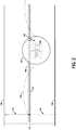
- FIG. 2 is a diagram illustrating a flight path for the aircraft 100 and an application of variability introduced to a flight path centerline.
- an ANP 130 of the aircraft 100 can be determined that indicates uncertainty in real time positioning of the aircraft 100 during flight based on information derived from the navigation system 104 onboard the aircraft 100.
- the ANP 130 is shown as an area in which the aircraft 100 is located to provide limits on a worst-case true physical position or geographic location of the aircraft 100.
- the ANP 130 may be determined based on a flight path centerline 142, which is based on a published procedure centerline flight path 132 information from the data storage 126 as well as the aircraft position and speed information available from the navigation system 104.
- An RNP instrument flight procedure 134 for the aircraft 100 is shown to indicate a fixed-route accuracy and containment boundaries 136 and 138 required during flight for the aircraft 100 to fly a path between two points along the flight path 132.
- the containment boundaries 136 and 138 are defined by the published procedure centerline flight path 132 with limits determined by associated margins 144 and 146 on either side of the published procedure centerline flight path 132.
- the system 102 onboard the aircraft 100 can calculate a new flight path 140 to be flown by the aircraft 100.
- a modification to the flight path centerline 142 resulting in the new flight path 140 may be based on spacing input 120 received from the ATC that indicates spacing requirements between the aircraft 100 and one or more other aircraft, as well as information 122 relating to communities underneath the flight path centerline 142. The modification can be calculated so that the aircraft 100 remains within the containment boundaries 136 and 138 of the RNP instrument flight procedure 134 while reducing noise impact to the communities underneath the flight path centerline 142 and meeting the spacing requirements of the ATC.
- the margin 144 is a distance away from the flight path centerline 142 along a first direction and the margin 146 is the same distance away from the flight path centerline 142 along a second direction
- a variation 148 can be calculated from the flight path centerline 142 along either direction (e.g., in Figure 2 along the second direction) so as to be within the distance of the margin 146.
- the aircraft 100 can then fly along the flight path 140 at the variation 148 from the flight path centerline 142 to introduce variability to the flight path 140.
- an alternate flight path can be calculated within the distance of the first margin 144 and the second margin 146 and accounting for the ANP 130.
- the variation 148 can be determined at different points along the flight path 140 due to changing values of the RNP instrument flight procedure 134 along the flight path centerline 142 and changing values of the ANP 130 during flight.
- the aircraft 100 can fly a dynamically varying flight path 140 on a straight procedure flight segment in the presence of varying ANP 130 while remaining with the allowed margins 144 and 146 about the flight path centerline 142.
- An amount of the variation 148 can be determined based on a difference between the real time positioning of the aircraft 100 and the margin 146, and this difference can be used to limit the modification to the flight path 140 to be flown by the aircraft 100.
- the modification to the flight path 140 to be flown by the aircraft 100 can be based on a residual flight margin available for use that is due to the ANP 130, the flight path centerline 142, the RNP instrument flight procedure 134, and the containment boundaries 136 and 138.
- the calculated flight margin is a distance available on each side of the flight path centerline 142 within the containment boundaries 136 and 138 that is available for use after accounting for the ANP 130.
- a flight error tolerance may be established based on flight guidelines that enable some default error in flight path.
- the flight margin can be determined at different points along the flight path 140 due to changing values of the RNP instrument flight procedure 134 along the flight path 140 and changing values of the ANP 130 during flight.
- the aircraft 100 can be steered, in approximately real time, in response to the information 122 relating to communities underneath the published procedure centerline 134. This may enable noise distribution of aircraft over communities.
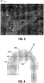
- Figure 3 illustrates an example an airport vicinity map 152 of recorded flight paths for approaches to an airport 156, from which a noise exposure map can be determined.
- Figure 3 illustrates the very high repeatability and precise path following capabilities of RNP approaches 158 compared to a similar number of tracks from conventional traffic management 154, and also illustrates a need for introducing variability into flight paths.
- Figure 4 is a diagram illustrating the flight path centerline 142 and an application of variability introduced in a context of a curved RNP approach procedure.
- variations 148a-b are shown at different points along the flight path but within the RNP procedure 134 boundaries and a boundary in consideration of measured ANP 135.
- the variation 148a is an example for a path deviation inside of the flight path centerline 142 during the turn, and the variation 148b is an example deviation outside of the flight path centerline 142.
- An available flight margin 150 is illustrated as the inner shaded area on either side of the flight path centerline 142.
- Figure 4 illustrates an example where the designated RNP value in the published procedure centerline 134 changes and the measured ANP 135 remains constant, so the available flight margin 150 in which flight path variation can be applied is commensurably changed.
- FIG. 5 is a block diagram illustrating example inputs to and functions performed by the aircraft 100 to generate a variable flight path 140.
- Track Variation interface functions 202 include interfaces that receive or output information to and from external sources.
- Example information received may include user input from flight crew interfaces 204, such as implemented on a flight deck device with a control and display unit in the form of a page with selectable actions and parameters and text providing status or option choices.
- Other example information includes a flight manager or electronic flight bag instrument procedure database 206, which includes instrument procedures available to be flown by the aircraft 100 and all required data for a procedure, such as waypoints and path segments that define centerlines, RNP values etc.
- Further example information includes an ANP 208 input, current aircraft position and state 210 (including aircraft position and speed information available from the navigation system 104), and traffic data 212.
- the traffic data 212 includes automatic dependent surveillance-broadcast in (ADS-B IN) data including aircraft identification, position and speed broadcast by an aircraft.
- An ADS-B traffic processor receives these broadcasts from other nearby aircraft and assembles them into data, a map, or a picture of nearby traffic that can be used by various applications, for example, for aircrew situational awareness, noise spreading, or coordinating variation paths to enhance safety or to increase timing and spacing effects.
- Track variation planning and update functions 214 receive information from the RNP interface functions 202, and define scope, objectives and limitations for variation in flight paths, and then also build the variation plan (or path) that will meet the objectives within the defined scope and limitations, including the limitation imposed by the procedure RNP bounds and the navigation performance.
- the Track Variation planning and update functions 214 can implement a "best effort" variation plan that scales the variation and the objectives to what is achievable or can request new objectives and/or scope from the user.
- the track variation planning and update functions 214 thus use the RNP instrument flight procedure performance requirements, measured ANP 208, flight mode information from the user input or from a flight manager function, and the current and trends in previous position and state to determine the flight margin (FM) 150.
- the flight margin 150 may be a margin within the procedure's defined RNP procedure containment boundaries 136 and 138 that can be used for purposeful variation.
- the flight margin 150 is determined by the procedure's baseline centerline, the ANP and detected trends in dynamic ANP changes, and the flight technical error (FTE) budget for the current flight mode (e.g., auto flight, flight director or manually flown) based on current and downstream RNP designation.
- FTE flight technical error
- flight margin (FM) RNP - ANP - FTE - a dynamically-adjusted buffer.
- the flight margin 150 is a margin or variation distance available on each side of the procedure baseline centerline, i.e., a flight margin of 0.5 NM means that the variation of 0.5 NM on either side of the centerline is available.
- the flight margin 150 may vary at different points along the planned route due to changing RNP values, for example, if the scope of the variable operation spans multiple RNAV/RNP procedures (e.g., an en-route, arrival, and approach procedures) or if a single procedure has different RNP values associated with different segments (e.g., many approach procedures have an RNP of 1 NM outside of the final approach fix (FAF) and 0.3 NM within the FAF).
- the flight margin 150 may also vary if ANP changes (for example, the number of GNSS satellites within of the navigation system 104 view changes).
- the track variation planning and update functions 214 may also take into account general operational constraints and preferences. These may be associated with types of procedures (e.g., approaches), specific procedures (e.g., one of the approach procedures for a specific airport), all procedures, or procedures with certain characteristics (e.g., RNP of 0.5 or less). These constraints and preferences can take general forms (e.g., use only 1/2 of the available flight margin for variation) or can be specific (e.g., avoid a left 0.5 NM for the last 2 NM of approach procedure x.1).
- the track variation planning and update functions 214 may also receive traffic location and velocity inputs from the traffic data ADS-B IN 212, develop traffic tracks over time, and combine data with instrument procedure data from procedure database 206 to build a variation-relevant picture of what nearby traffic is doing.
- the variation-relevant picture includes information indicating aircraft traffic and associated procedures of the traffic, and offsets or variations from the procedure baseline centerlines for each traffic aircraft.
- the track variation planning and update functions 214 determines applicable variations that may consider noise spreading or path spreading for safety enhancements by randomly selecting or specifying applicable variation targets.
- Some strategies for the variable path generation include fixed distance offsets, fixed margin offsets (e.g. offset related to RNP-ANP), , using damped pseudo-random path variation functions, using fixed offset ADS-B stagger (e.g., maximize offset from aircraft(s) in front using other aircraft position feedback) from ADS-B IN, or using fixed margin ADS-B stagger.
- the track variation planning and update functions 214 may also determine path stretching or compression for spacing and time-of-arrival control using sinusoidal or S-turn path stretching, constrained vectors path stretching (shallow angle off path, followed by shallow angle return to path, repeat as required), damped pseudo-random path variation, or curved segment shortening or lengthening.
- the track variation planning and update functions 214 may use ADS-B or other air traffic position data to coordinate the spacing and time-of-arrival path variations with the paths and locations of other aircraft to enhance safety or to reduce noise impacts.
- the RNP with variation plan monitor functions 216 review outputs of the Track Variation planning and update functions 214 for changes that may occur due to changing ANP 208 input.
- the RNP with Variation Plan Monitor Functions 216 further display the performance of the aircraft with the respect to the bounding procedure baseline centerline based RNP boundaries, the current ANP 208, and the currently active variation path from the track variation planning and update functions 214.
- RNP path execution functions 218 cause the aircraft 100 to fly the modified flight path within the limits of the RNP procedure.
- the RNP path execution function 218 could, for example, take advantage of native functions within the flight manager 105 (as in Figure 1 ) such as processors 125 and retrieval of executable instructions for RNP monitoring 129.
- Figure 6 shows a flowchart of an example method 250 for modifying the flight path 140 of the aircraft 100, according to an example embodiment.
- Method 250 shown in Figure 6 presents an embodiment of a method that could be used with the aircraft 100 shown in Figure 1 , for example, and may be performed by the system 102.
- devices or systems may be used or configured to perform logical functions presented in Figure 6 .
- components of the devices and/or systems may be configured to perform the functions such that the components are actually configured and structured (with hardware and/or software) to enable such performance.
- components of the devices and/or systems may be arranged to be adapted to, capable of, or suited for performing the functions, such as when operated in a specific manner.
- Method 250 may include one or more operations, functions, or actions as illustrated by one or more of blocks 252-264. Although the blocks are illustrated in a sequential order, these blocks may also be performed in parallel, and/or in a different order than those described herein. Also, the various blocks may be combined into fewer blocks, divided into additional blocks, and/or removed based upon the desired implementation.
- each block may represent a module, a segment, or a portion of program code, which includes one or more instructions executable by a processor for implementing specific logical functions or steps in the process.
- the program code may be stored on any type of computer readable medium or data storage, for example, such as a storage device including a disk or hard drive. Further, the program code can be encoded on a computer-readable storage media in a machine-readable format, or on other non-transitory media or articles of manufacture.
- the computer readable medium may include non-transitory computer readable medium or memory, for example, such as computer-readable media that stores data for short periods of time like register memory, processor cache and Random Access Memory (RAM).
- the computer readable medium may also include non-transitory media, such as secondary or persistent long term storage, like read only memory (ROM), optical or magnetic disks, compact-disc read only memory (CD-ROM), for example.
- the computer readable media may also be any other volatile or non-volatile storage systems.
- the computer readable medium may be considered a tangible computer readable storage medium, for example.
- each block in Figure 6 may represent circuitry that is wired to perform the specific logical functions in the process.
- Alternative implementations are included within the scope of the example embodiments of the present disclosure in which functions may be executed out of order from that shown or discussed, including substantially concurrent or in reverse order, depending on the functionality involved, as would be understood by those reasonably skilled in the art.
- the method 250 includes receiving real time positioning information for the aircraft 100, such as from the navigation system 104.
- the method 250 includes receiving the ANP of the aircraft 100, and the ANP indicates uncertainty in the real time positioning of the aircraft 100 during flight based on information collected from the navigation system 104 onboard the aircraft 100.
- the method 250 includes receiving the RNP instrument flight procedure 134 for the aircraft 100, and the RNP instrument flight procedure indicates a fixed-route accuracy and the containment boundaries 136 and 138 required during flight for the aircraft 100 to fly a path between two points along the flight path 132.
- the containment boundaries 136 and 138 are defined by the flight path centerline 142 with limits determined by the associated margins 144 and 146.
- the method 250 includes receiving the spacing input 120 from the ATC that indicates spacing requirements between the aircraft 100 and one or more other aircraft.
- the method 250 includes receiving information 122 relating to communities underneath the published procedure 134.
- the method 250 is performed by the system 102 onboard the aircraft 100, and the spacing input 120 from the ATC and the information 122 relating to communities underneath the flight path is received by the aircraft 100 wirelessly communicating with one or more ground systems.
- the method 250 includes calculating, by the system 102 onboard the aircraft 100, a modification to the flight path 140 to be flown by the aircraft 100 that causes the aircraft 100 to remain within the containment boundaries 136 and 138 of the RNP instrument flight procedure 134 while reducing noise impact to the communities underneath the published procedure 134 and meeting the spacing requirements of the ATC.
- the associated margins 144 and 146 include a first margin a distance away from the flight path centerline 142 along a first direction and a second margin the distance away from the flight path centerline 142 along a second direction, and the variation 148 from the flight path centerline 142 can be calculated along the first direction within the distance of the first margin.
- a difference between the real time positioning of the aircraft 100 and the first margin can be determined and used to limit the modification to the flight path to be flown by the aircraft 100.
- the modification to the flight path to be flown by the aircraft 100 can be determined as a random modification, and the modification adds variability to the flight path to distribute noise over the communities underneath the flight path.
- the flight margin 150 available for use can be determined based on the ANP 130, the flight path centerline 142, the RNP instrument flight procedure 134, and a flight error tolerance.
- the information indicating position or variations from flight path centerlines for other aircraft can be received, and the modification to the flight path can be determined based on the variations from flight path centerlines of published RNP procedures for the other aircraft so as to meet the spacing requirements of the ATC, or so as to reduce community noise impacts.
- the method 250 includes displaying a visual representation of a modified flight path for the aircraft 100.
- the visual representation can be provided on the display 114.
- Figure 7 shows a flowchart of an example method for use with the method 250, according to an example embodiment.
- functions include determining the flight margin at different points along the flight path due to changing values of the RNP along the flight path and changing values of the ANP during flight.
- FIG. 8 shows a flowchart of an example method for use with the method 250, according to an example embodiment.
- functions include determining the modified flight path for the aircraft so as to steer the aircraft, in approximately real time, in response to the information relating to communities that can include real time community noise inquiries.
- Figure 9 shows a flowchart of an example method for use with the method 250, according to an example embodiment.
- functions include displaying a visual representation of flight paths taken by a plurality of aircraft, variation margins that can be achieved within RNPs for the plurality of aircraft, and a noise exposure map for the communities underneath the RNPs. Such information may be displayed on the display 114.
- the visual representation may further show flight paths taken by the aircraft as well as variation margins that can be achieved within procedure RNP containment boundaries for such aircraft.
- FIG. 10 shows a flowchart of an example method for use with the method 250, according to an example embodiment.
- functions include displaying a visual representation of the containment boundaries 136 and 138 of the RNP instrument flight procedure 134.
- the visual representation in this example may further include the variation path centerline, the ANP, and the current position of the aircraft, for example.
- Figure 11 shows a flowchart of an example method for use with the method 250, according to an example embodiment.
- functions include causing the aircraft 100 to fly the modified flight path.
- Example systems and methods described enable many benefits including noise spreading, localized (and potentially dynamic) noise avoidance, and path stretching or compression for longitudinal spacing adjustments (ground requested or aircrew initiated). Further, safety enhancements can be realized using path variation randomization to further decrease a probability that inadvertently co-path flights are on the same path.
Landscapes
- Engineering & Computer Science (AREA)
- Physics & Mathematics (AREA)
- General Physics & Mathematics (AREA)
- Aviation & Aerospace Engineering (AREA)
- Radar, Positioning & Navigation (AREA)
- Remote Sensing (AREA)
- Automation & Control Theory (AREA)
- Traffic Control Systems (AREA)
- Navigation (AREA)
Abstract
Description
- The present disclosure relates generally to methods for modifying a flight path of an aircraft, and more particularly to calculating, by a system onboard the aircraft, a modification to the flight path to be flown by the aircraft that causes the aircraft to remain within containment boundaries of a Required Navigation Performance (RNP) instrument flight procedure while reducing noise impact to the communities underneath the flight path and meeting the spacing requirements of the air traffic controller.
- Performance-Based Navigation (PBN), including the widely used Required Navigation Performance (RNP) and Area Navigation (RNAV) instrument procedures, are key parts of airspace modernization worldwide. For example, RNAV and RNP-based procedure deployment is a component of the United States' airspace modernization, the Federal Aviation Administration (FAA) NextGen program, that is implementing new PBN routes and procedures to leverage emerging technologies and aircraft navigation capabilities. Modem commercial aircraft fly PBN flight paths with very high precision. The aircraft can exploit high accuracy provided by global positioning system (GPS)-based navigation systems, modem Flight Management Systems (FMSs) and Flight Control Systems (FCSs). Due to this highly accurate path-keeping capability, the use of PBN removes much of the variability traditionally seen in aircraft flight paths, and results in highly repeatable operations.
- The benefits of using RNAV and RNP procedures thus include improved aircraft stability on approach, improved aircraft predictability for air traffic control, reduced fuel burn, lower track miles, improved airport capacity, reduced (concentrated) noise footprints, and paths tailored to avoid noise sensitive areas. However, these same procedures can be detrimental for the exact reason that modem commercial aircraft fly RNAV and RNP defined flight paths with very high precision.
- While accuracy and repeatability can be desirable, there are a number of operational and safety issues that could benefit from judicious variation in flight paths. For example, in approach operations, a concentrated noise footprint stemming from repeatable operations creates noise issues for communities under the flight paths. In addition, fixed, consistent flight paths mean that air traffic controllers (ATC) lose some ability to fine-tune aircraft longitudinal spacing that the ATC once exercised by vectoring traffic. Furthermore, highly repeatable path-keeping traffic means a higher risk of loss of separation between aircraft if the concentrated portions of the traffic streams conflict.
- Existing solutions related to path variation with use of RNP are limited to offsetting flight paths relative to the originally-defined procedure. For example, ATC may pull some traffic off of fixed routes to avoid or organize traffic using vectors. However, this negates efficiency and other benefits of fixed track use, and limits the ability of on-board aircraft systems to provide alerts supporting high integrity guidance and navigation. Further solutions provide for aircraft to fly an offset path, in which both the offset path and associated boundaries are shifted by an amount of the offset. However, this method is not usable in constrained airspace associated with arrival, approach and departure routes in a vicinity of airports where locations of original boundaries may be integral to safe operations.
- What is needed is a method that enables use of full margins of an RNP procedure based on measured performance to retain efficiency while also addressing noise concerns and manage spacing/timing of aircraft.
- In one example, a method for modifying a flight path of an aircraft is described. The method comprises receiving real time positioning information for an aircraft, and receiving an actual navigation performance (ANP) of the aircraft. The ANP indicates uncertainty in the real time positioning of the aircraft based on information collected from a navigation system onboard the aircraft. The method also comprises receiving a required navigation performance (RNP) instrument flight procedure for the aircraft, and the RNP instrument flight procedure indicates a fixed-route accuracy and containment boundaries required during flight for the aircraft to fly a path between two points along a flight path. The containment boundaries are defined by a flight path centerline with limits determined by associated margins. The method also comprises receiving spacing input from an air traffic controller that indicates spacing requirements between the aircraft and one or more other aircraft, and receiving information relating to communities underneath the flight path. The method also comprises calculating, by a system onboard the aircraft, a modification to the flight path to be flown by the aircraft that causes the aircraft to remain within the containment boundaries of the RNP instrument flight procedure while reducing noise impact to the communities underneath the flight path and meeting the spacing requirements of the air traffic controller, and displaying a visual representation of a modified flight path for the aircraft.
- In another example, a system is described that comprises a communication interface for receiving real time positioning of an aircraft during flight, and an actual navigation performance (ANP) of the aircraft. The ANP indicates uncertainty in the real time positioning of the aircraft. The communication interface also for receiving information for a required navigation performance (RNP) instrument flight procedure for the aircraft, and the RNP instrument flight procedure indicates a fixed-route accuracy and containment boundaries required during flight for the aircraft to fly a path between two points along a flight path. The containment boundaries are defined by a flight path centerline with limits determined by associated margins. The system also includes data storage for storing spacing input from an air traffic controller that indicates spacing requirements between the aircraft and one or more other aircraft, and information relating to communities underneath the flight path. The system also includes one or more processors for executing instructions stored on the data storage to calculate a modification to the flight path to be flown by the aircraft that causes the aircraft to remain within the containment boundaries of the RNP instrument flight procedure while reducing noise impact to the communities underneath the flight path and meeting the spacing requirements of the air traffic controller, and an output interface for outputting a modified flight path for the aircraft.
- In another example, a non-transitory computer readable storage medium is described having stored therein instructions, that when executed by a system having one or more processors, causes the system to perform functions. The functions comprise receiving real time positioning information of an aircraft, and receiving an actual navigation performance (ANP) of the aircraft. The ANP indicates uncertainty in the real time positioning of the aircraft based on information collected from a navigation system onboard the aircraft. The functions also comprise receiving a required navigation performance (RNP) instrument flight procedure, and the RNP indicates a fixed-route accuracy and containment boundaries required during flight for the aircraft to fly a path between two points along a flight path. The containment boundaries are defined by a flight path centerline with limits determined by associated margins. The functions also comprise receiving spacing input from an air traffic controller that indicates spacing requirements between the aircraft and one or more other aircraft, and receiving information relating to communities underneath the flight path. The functions also comprise calculating a modification to the flight path to be flown by the aircraft that causes the aircraft to remain within the containment boundaries of the RNP while reducing noise impact to the communities underneath the flight path and meeting the spacing requirements of the air traffic controller, and displaying a visual representation of a modified flight path for the aircraft.
- The features, functions, and advantages that have been discussed can be achieved independently in various embodiments or may be combined in yet other embodiments further details of which can be seen with reference to the following description and drawings.
- The novel features believed characteristic of the illustrative embodiments are set forth in the appended claims. The illustrative embodiments, however, as well as a preferred mode of use, further objectives and descriptions thereof, will best be understood by reference to the following detailed description of an illustrative embodiment of the present disclosure when read in conjunction with the accompanying drawings, wherein:
-
Figure 1 is a block diagram of an aircraft, according to an example embodiment. -
Figure 2 is a diagram illustrating a flight path for the aircraft and an application of variability introduced from a flight path centerline within defined limits of the RNP procedure, according to an example embodiment. -
Figure 3 illustrates an example of concentration of the recorded flight paths for RNP approaches to an airport relative to traditional traffic management, according to an example embodiment. -
Figure 4 is a diagram illustrating a flight path for the aircraft and an application of variability introduced to manage path length in a context of a curved RNP approach procedure, according to an example embodiment. -
Figure 5 is a block diagram illustrating example inputs to and functions performed by the aircraft to introduce variability into the flight path, according to an example embodiment. -
Figure 6 shows a flowchart of an example method for modifying the flight path of the aircraft, according to an example embodiment. -
Figure 7 shows a flowchart of an example method for use with the method, according to an example embodiment. -
Figure 8 shows a flowchart of an example method for use with the method, according to an example embodiment. -
Figure 9 shows a flowchart of an example method for use with the method, according to an example embodiment. -
Figure 10 shows a flowchart of an example method for use with the method, according to an example embodiment. -
Figure 11 shows a flowchart of an example method for use with the method, according to an example embodiment. - Disclosed embodiments will now be described more fully hereinafter with reference to the accompanying drawings, in which some, but not all of the disclosed embodiments are shown. Indeed, several different embodiments may be described and should not be construed as limited to the embodiments set forth herein. Rather, these embodiments are described so that this disclosure will be thorough and complete and will fully convey the scope of the disclosure to those skilled in the art.
- Described below are example systems and methods to implement variation in flight paths that can assist with spreading a noise footprint stemming from repeatable operations as well as reducing concentrated traffic patterns.
- An example method for modifying a flight path of an aircraft includes receiving real time positioning information for an aircraft, receiving a calculated actual navigation performance (ANP) of the aircraft, receiving a required navigation performance (RNP) instrument flight procedure for the aircraft, receiving spacing input from an air traffic controller that indicates spacing requirements between the aircraft and one or more other aircraft, receiving information relating to communities underneath the flight path, calculating, by a system onboard the aircraft, a modification to the flight path to be flown by the aircraft that causes the aircraft to remain within the containment boundaries of the RNP instrument flight procedure while reducing noise impact to the communities underneath the flight path and meeting the spacing requirements of the air traffic controller, and displaying a visual representation of a modified flight path for the aircraft.
- Referring now to
Figure 1 , a block diagram of anaircraft 100 is illustrated, according to an example embodiment. Theaircraft 100 includes asystem 102 onboard theaircraft 100 that is in communication with anavigation system 104 and aflight manager 105 onboard theaircraft 100. - The
system 102 includes acommunication interface 106,data storage 108, one or more processor(s) 110, anoutput interface 112, and adisplay 114 each connected to acommunication bus 116. Thesystem 102 may also include hardware to enable communication within thesystem 102 and between thesystem 102 and other devices (not shown). The hardware may include transmitters, receivers, and antennas, for example. - The
communication interface 106 may be a wireless interface and/or one or more wireline interfaces that allow for both short-range communication and long-range communication to one or more networks or to one or more remote devices. Such wireless interfaces may provide for communication under one or more wireless communication protocols, such as voice communication using Very High Frequency (VHF), VHF Data link (VDL), VDL Mode 2, Aircraft Communications Addressing and Reporting System (ACARS) digital communications over VHF radio and satellite communications (SATCOM), Bluetooth, WiFi (e.g., an institute of electrical and electronic engineers (IEEE) 802.11 protocol), Long-Term Evolution (LTE), cellular communications, near-field communication (NFC), and/or other wireless communication protocols. Such wireline interfaces may include aircraft data buses such as Aeronautical Radio, Incorporated (ARINC) 429, 629, or 664 based interfaces, Ethernet interface, a Universal Serial Bus (USB) interface, or similar interface to communicate via a wire, a twisted pair of wires, a coaxial cable, an optical link, a fiber-optic link, or other physical connection to a wireline network. - Thus, the
communication interface 106 may be configured to receive input data from one or more devices, and may also be configured to send output data to other devices. In some examples, thecommunication interface 106 may also maintain and manage records of data received and sent by thesystem 102. Thecommunication interface 106 may also include a receiver and transmitter to receive and send data. In other examples, thecommunication interface 106 may also include a user-interface, such as a keyboard, microphone, touchscreen, etc., to receive inputs as well. - In examples described below, the
communication interface 106 receives real time positioning of theaircraft 100 during flight from thenavigation system 104, and also receives an actual navigation performance (ANP) of theaircraft 100 as calculated or determined by real-time monitoring of uncertainty in received navigation signals from thenavigation system 104. Thus, the ANP indicates a magnitude of potential uncertainty in the real time positioning of theaircraft 100 during flight. Furthermore, thecommunication interface 106 receives information for a required navigation performance (RNP) instrument flight procedure for theaircraft 100, from ground-based traffic controllers, or from theflight manager 105, that indicates a fixed-route accuracy and containment boundaries required during flight for theaircraft 100 to fly a path between two points along a flight path. The containment boundaries are defined by a flight path centerline with limits determined by associated margins. - The
data storage 108 may include or take the form of one or more computer-readable storage media that can be read or accessed by the processor(s) 110. The computer-readable storage media can include volatile and/or non-volatile storage components, such as optical, magnetic, organic or other memory or disc storage, which can be integrated in whole or in part with the processor(s) 110. Thedata storage 108 is considered non-transitory computer readable media. In some embodiments, thedata storage 108 can be implemented using a single physical device (e.g., one optical, magnetic, organic or other memory or disc storage unit), while in other embodiments, thedata storage 108 can be implemented using two or more physical devices. - The
data storage 108 thus is a non-transitory computer readable storage medium, andexecutable instructions 118 are stored thereon. Theinstructions 118 include computer executable code. When theinstructions 118 are executed by thesystem 102 that has the one or more processor(s) 110, thesystem 102 is caused to perform functions. Such functions include calculating modifications to a flight path, and these functions are described more fully below. - The
data storage 108 furtherstores spacing input 120 from an air traffic controller (ATC) that indicates spacing requirements between theaircraft 100 and one or more other aircraft, andinformation 122 relating to communities underneath the flight path. Thespacing input 120 and theinformation 122 relating to communities underneath the flight path may be received at thecommunication interface 106 and then stored in thedata storage 108. - The processor(s) 110 may be a general-purpose processor or a special purpose processor (e.g., digital signal processors, application specific integrated circuits, etc.). The processor(s) 110 may receive inputs from the
communication interface 106, and process the inputs to generate outputs that are stored in thedata storage 108 and output to thedisplay 114. The processor(s) 110 can be configured to execute the executable instructions 118 (e.g., computer-readable program instructions) that are stored in thedata storage 108 and are executable to provide the functionality of thesystem 102 described herein. - As one example, the processor(s) 110 execute the
executable instructions 118 stored on thedata storage 108 to calculate a modification to the flight path to be flown by theaircraft 100 that causes theaircraft 100 to remain within the containment boundaries of the RNP instrument flight procedure while reducing noise impact to the communities underneath the flight path and meeting the spacing requirements of the air traffic controller. - The processor(s) 110 can execute the
executable instructions 118 stored in thedata storage 108 to perform functions in real-time during flight of theaircraft 100. Such function can then occur with no or little delay to process additional data received from other sources or through manual input. The real time processing means that the processor(s) 110 perform the actions during flight of theaircraft 100. The real time processing may continually process information received from thecommunication interface 106. Put another way, the real time aspect includes thesystem 102 deciding to modify the flight path of theaircraft 100 substantially immediately upon receiving new or updated spacing requirements between theaircraft 100 and one or more other aircraft, and new or updatedinformation 122 relating to communities underneath the flight path. By the term "substantially" it is meant that the recited characteristic, parameter, or value need not be achieved exactly, but that deviations or variations, including for example, tolerances, measurement error, measurement accuracy limitations and other factors known to skill in the art, may occur in amounts that do not preclude the effect the characteristic was intended to provide. - In one example, the
information 122 relating to communities includes real time community noise inquiries received by thecommunication interface 106, and the processor(s) 110 further determine the modified flight path for theaircraft 100 so as to steer theaircraft 100, in approximately real time, in response to theinformation 122. Here, "approximately" indicates with little to no delay, or with no delay due to processing of additional data. - The
output interface 112 outputs a modified flight path for theaircraft 100. Theoutput interface 112 can output the modified flight path to thedisplay 114 or to other aircraft or ground-based systems as well. Thus, theoutput interface 112 may be similar to thecommunication interface 106 and can be a wireless interface (e.g., transmitter) or a wired interface as well. - The
navigation system 104 includes a Global Navigation Satellite System (GNSS)receiver 119 configured to provide data that is typical of well-known Global Positioning System (GPS) systems, such as the coordinates of theaircraft 100. Position estimates provided by theGNSS receiver 119 can be replaced or augmented to enhance accuracy and stability by inputs from other sensors, such motion andrate sensors 121, camera andoptical sensors 123, and radio frequency (RF)systems 124. Such navigation data may be utilized by thesystem 102 for various functions, such as to navigate to a target position. Thenavigation system 104 may also include hardware to enable communication within thenavigation system 104 and between thenavigation system 104 and other devices (not shown). The hardware may include transmitters, receivers, and antennas, for example. - The
navigation system 104 may also include other components such as a multi-mode receiver that uses other aviation-approved sources of navigation information. TheRF systems 124 may include radar systems for ranging and target detection or Instrument Landing Systems (ILS) and various GNSS Augmentation Systems such as the Ground Based Augmentation System (GBAS). The camera andoptical sensors 123 may include light detection and ranging (LIDAR) systems, laser detection and ranging (LADAR) systems, and/or an infrared or forward-looking infrared (FLIR) system, among other possibilities. - The camera and
optical sensors 123 can also include an imaging system, such as a video camera, to capture image data from an environment. As a specific example, charge-coupled device (CCD) cameras or complementary metal-oxide-semiconductor (CMOS) cameras can be used, among other possibilities. Thus, the camera andoptical sensors 123 can include a visual camera. The camera andoptical sensors 123 can also include a night-vision camera and/or a forward looking infrared radar device or an infrared camera. The camera andoptical sensors 123 may capture imagery of the environment and compare the imagery to what is expected given a current estimated position to help with navigation. - The
flight manager 105 includes one or more processor(s) 125 that accessesdata storage 126 to retrieve information for communication with thesystem 102 through anoutput interface 127. As one example, theflight manager 105 retrieves an RNPinstrument flight procedure 128 for theaircraft 100 from thedata storage 126 and provides the RNPinstrument flight procedure 128 to thesystem 102 via theoutput interface 127. The RNPinstrument flight procedure 128 indicates a fixed-route accuracy and containment boundaries required during flight for theaircraft 100 to fly a path between two points along a flight path. The processor(s) 125 may also execute instructions forRNP monitoring 129 stored within thedata storage 126 to monitor a flight path of theaircraft 100. - The
aircraft 100 can be operated using PBN-based flight path variation to intentionally add beneficial variability into aircraft track-keeping, while honoring any required performance constraints while executing area navigation operations. New functions described herein provide variation management and alternate flight paths constrained by required performance that are integrated with existing flight management system functions. The functions can enhance safety by de-concentrating air traffic, reduce environmental impact by spreading noise, and can also provide additional longitudinal aircraft spacing control in arrival and approach operations. - The PBN flight path variation exploits existing measurement of real-time position uncertainty determined in an actual navigation performance (ANP) to dynamically bound potential track variation to predefined limits. The
system 102 will add variability to the tracking performance during RNAV and RNP procedures while remaining within the constraints of the defined required performance by using real-time ANP. These functions can be used as airplane stand-alone capabilities to improve noise distributions, meet timing or spacing goals and/or to enhance safety by implementing airline specific open-loop variation distributions or aircrew input variations to address known or expected issue areas. These capabilities can also be integrated with ground systems to provide additional benefits. - Within examples, PBN and RNP implementations include limits on allowable variations, and containment boundaries of position of the
aircraft 100 as referenced to a flight path centerline that can be tracked using real-time monitoring of the aircraft position and ANP uncertainty based on received navigation signals. RNP is distinct from general RNAV systems in that it requires a real-time measurement of ANP, which is an estimation of a maximum position uncertainty of theaircraft 100. - Generally, ANP has been used only as a trigger value for performance and alerting. Real-time determined ANP that is substantially better than required for the
aircraft 100 has not been exploited. While guidelines for and certified budgets for flight paths may be on the order of half the required performance value (e.g., 0.5 nautical mile (NM) for an RNP 1 procedure), navigation systems can often provide a substantially smaller ANP (e.g., 0.04 NM). This difference, or a portion thereof, can be used in real-time to provide purposeful variation in a defined flight path. As ANP changes, theaircraft 100 can adjust allowed variations to ensure flight performance requirements are met. -
Figure 2 is a diagram illustrating a flight path for theaircraft 100 and an application of variability introduced to a flight path centerline. InFigure 2 , anANP 130 of theaircraft 100 can be determined that indicates uncertainty in real time positioning of theaircraft 100 during flight based on information derived from thenavigation system 104 onboard theaircraft 100. TheANP 130 is shown as an area in which theaircraft 100 is located to provide limits on a worst-case true physical position or geographic location of theaircraft 100. TheANP 130 may be determined based on a flight path centerline 142, which is based on a published procedurecenterline flight path 132 information from thedata storage 126 as well as the aircraft position and speed information available from thenavigation system 104. - An RNP
instrument flight procedure 134 for theaircraft 100 is shown to indicate a fixed-route accuracy andcontainment boundaries aircraft 100 to fly a path between two points along theflight path 132. Thecontainment boundaries centerline flight path 132 with limits determined by associatedmargins centerline flight path 132. - Since a possible location of the
aircraft 100, represented by theANP 130, is determined to be within thecontainment boundaries instrument flight procedure 134, there is additional spacing available within themargins flight path centerline 142. Thus, thesystem 102 onboard theaircraft 100 can calculate anew flight path 140 to be flown by theaircraft 100. A modification to the flight path centerline 142 resulting in thenew flight path 140 may be based on spacinginput 120 received from the ATC that indicates spacing requirements between theaircraft 100 and one or more other aircraft, as well asinformation 122 relating to communities underneath theflight path centerline 142. The modification can be calculated so that theaircraft 100 remains within thecontainment boundaries instrument flight procedure 134 while reducing noise impact to the communities underneath the flight path centerline 142 and meeting the spacing requirements of the ATC. - In one example, the
margin 144 is a distance away from the flight path centerline 142 along a first direction and themargin 146 is the same distance away from the flight path centerline 142 along a second direction, and avariation 148 can be calculated from the flight path centerline 142 along either direction (e.g., inFigure 2 along the second direction) so as to be within the distance of themargin 146. Here, theaircraft 100 can then fly along theflight path 140 at thevariation 148 from the flight path centerline 142 to introduce variability to theflight path 140. Thus, an alternate flight path can be calculated within the distance of thefirst margin 144 and thesecond margin 146 and accounting for theANP 130. - As shown in
Figure 2 , thevariation 148 can be determined at different points along theflight path 140 due to changing values of the RNPinstrument flight procedure 134 along the flight path centerline 142 and changing values of theANP 130 during flight. Thus, theaircraft 100 can fly a dynamically varyingflight path 140 on a straight procedure flight segment in the presence of varyingANP 130 while remaining with the allowedmargins flight path centerline 142. - An amount of the
variation 148 can be determined based on a difference between the real time positioning of theaircraft 100 and themargin 146, and this difference can be used to limit the modification to theflight path 140 to be flown by theaircraft 100. - In other examples, the modification to the
flight path 140 to be flown by theaircraft 100 can be based on a residual flight margin available for use that is due to theANP 130, the flight path centerline 142, the RNPinstrument flight procedure 134, and thecontainment boundaries containment boundaries ANP 130. A flight error tolerance may be established based on flight guidelines that enable some default error in flight path. Further, the flight margin can be determined at different points along theflight path 140 due to changing values of the RNPinstrument flight procedure 134 along theflight path 140 and changing values of theANP 130 during flight. - By applying modifications to the
flight path 140, theaircraft 100 can be steered, in approximately real time, in response to theinformation 122 relating to communities underneath the publishedprocedure centerline 134. This may enable noise distribution of aircraft over communities. -
Figure 3 illustrates an example anairport vicinity map 152 of recorded flight paths for approaches to anairport 156, from which a noise exposure map can be determined.Figure 3 illustrates the very high repeatability and precise path following capabilities of RNP approaches 158 compared to a similar number of tracks fromconventional traffic management 154, and also illustrates a need for introducing variability into flight paths. -
Figure 4 is a diagram illustrating the flight path centerline 142 and an application of variability introduced in a context of a curved RNP approach procedure. InFigure 4 ,variations 148a-b are shown at different points along the flight path but within theRNP procedure 134 boundaries and a boundary in consideration of measuredANP 135. Thevariation 148a is an example for a path deviation inside of the flight path centerline 142 during the turn, and thevariation 148b is an example deviation outside of theflight path centerline 142. Anavailable flight margin 150 is illustrated as the inner shaded area on either side of theflight path centerline 142.Figure 4 illustrates an example where the designated RNP value in the publishedprocedure centerline 134 changes and the measuredANP 135 remains constant, so theavailable flight margin 150 in which flight path variation can be applied is commensurably changed. -
Figure 5 is a block diagram illustrating example inputs to and functions performed by theaircraft 100 to generate avariable flight path 140. Track Variation interface functions 202 include interfaces that receive or output information to and from external sources. Example information received may include user input from flight crew interfaces 204, such as implemented on a flight deck device with a control and display unit in the form of a page with selectable actions and parameters and text providing status or option choices. Other example information includes a flight manager or electronic flight baginstrument procedure database 206, which includes instrument procedures available to be flown by theaircraft 100 and all required data for a procedure, such as waypoints and path segments that define centerlines, RNP values etc. Further example information includes anANP 208 input, current aircraft position and state 210 (including aircraft position and speed information available from the navigation system 104), andtraffic data 212. Thetraffic data 212 includes automatic dependent surveillance-broadcast in (ADS-B IN) data including aircraft identification, position and speed broadcast by an aircraft. An ADS-B traffic processor receives these broadcasts from other nearby aircraft and assembles them into data, a map, or a picture of nearby traffic that can be used by various applications, for example, for aircrew situational awareness, noise spreading, or coordinating variation paths to enhance safety or to increase timing and spacing effects. - Track variation planning and update functions 214 receive information from the RNP interface functions 202, and define scope, objectives and limitations for variation in flight paths, and then also build the variation plan (or path) that will meet the objectives within the defined scope and limitations, including the limitation imposed by the procedure RNP bounds and the navigation performance. In an example where the objectives cannot be met within the limits and scope imposed, the Track Variation planning and update functions 214 can implement a "best effort" variation plan that scales the variation and the objectives to what is achievable or can request new objectives and/or scope from the user.
- The track variation planning and update functions 214 thus use the RNP instrument flight procedure performance requirements, measured
ANP 208, flight mode information from the user input or from a flight manager function, and the current and trends in previous position and state to determine the flight margin (FM) 150. Theflight margin 150 may be a margin within the procedure's defined RNPprocedure containment boundaries flight margin 150 is determined by the procedure's baseline centerline, the ANP and detected trends in dynamic ANP changes, and the flight technical error (FTE) budget for the current flight mode (e.g., auto flight, flight director or manually flown) based on current and downstream RNP designation. As an example, flight margin (FM) = RNP - ANP - FTE - a dynamically-adjusted buffer. Theflight margin 150 is a margin or variation distance available on each side of the procedure baseline centerline, i.e., a flight margin of 0.5 NM means that the variation of 0.5 NM on either side of the centerline is available. - The
flight margin 150 may vary at different points along the planned route due to changing RNP values, for example, if the scope of the variable operation spans multiple RNAV/RNP procedures (e.g., an en-route, arrival, and approach procedures) or if a single procedure has different RNP values associated with different segments (e.g., many approach procedures have an RNP of 1 NM outside of the final approach fix (FAF) and 0.3 NM within the FAF). Theflight margin 150 may also vary if ANP changes (for example, the number of GNSS satellites within of thenavigation system 104 view changes). - The track variation planning and update functions 214 may also take into account general operational constraints and preferences. These may be associated with types of procedures (e.g., approaches), specific procedures (e.g., one of the approach procedures for a specific airport), all procedures, or procedures with certain characteristics (e.g., RNP of 0.5 or less). These constraints and preferences can take general forms (e.g., use only 1/2 of the available flight margin for variation) or can be specific (e.g., avoid a left 0.5 NM for the last 2 NM of approach procedure x.1).
- The track variation planning and update functions 214 may also receive traffic location and velocity inputs from the traffic data ADS-B IN 212, develop traffic tracks over time, and combine data with instrument procedure data from
procedure database 206 to build a variation-relevant picture of what nearby traffic is doing. The variation-relevant picture includes information indicating aircraft traffic and associated procedures of the traffic, and offsets or variations from the procedure baseline centerlines for each traffic aircraft. - The track variation planning and update functions 214 determines applicable variations that may consider noise spreading or path spreading for safety enhancements by randomly selecting or specifying applicable variation targets. Some strategies for the variable path generation include fixed distance offsets, fixed margin offsets (e.g. offset related to RNP-ANP), , using damped pseudo-random path variation functions, using fixed offset ADS-B stagger (e.g., maximize offset from aircraft(s) in front using other aircraft position feedback) from ADS-B IN, or using fixed margin ADS-B stagger.
- The track variation planning and update functions 214 may also determine path stretching or compression for spacing and time-of-arrival control using sinusoidal or S-turn path stretching, constrained vectors path stretching (shallow angle off path, followed by shallow angle return to path, repeat as required), damped pseudo-random path variation, or curved segment shortening or lengthening. The track variation planning and update functions 214 may use ADS-B or other air traffic position data to coordinate the spacing and time-of-arrival path variations with the paths and locations of other aircraft to enhance safety or to reduce noise impacts.
- The RNP with variation plan monitor functions 216 review outputs of the Track Variation planning and update functions 214 for changes that may occur due to changing
ANP 208 input. The RNP with Variation Plan Monitor Functions 216 further display the performance of the aircraft with the respect to the bounding procedure baseline centerline based RNP boundaries, thecurrent ANP 208, and the currently active variation path from the track variation planning and update functions 214. - Following, RNP path execution functions 218 cause the
aircraft 100 to fly the modified flight path within the limits of the RNP procedure. The RNPpath execution function 218 could, for example, take advantage of native functions within the flight manager 105 (as inFigure 1 ) such asprocessors 125 and retrieval of executable instructions forRNP monitoring 129. -
Figure 6 shows a flowchart of anexample method 250 for modifying theflight path 140 of theaircraft 100, according to an example embodiment.Method 250 shown inFigure 6 presents an embodiment of a method that could be used with theaircraft 100 shown inFigure 1 , for example, and may be performed by thesystem 102. Further, devices or systems may be used or configured to perform logical functions presented inFigure 6 . In some instances, components of the devices and/or systems may be configured to perform the functions such that the components are actually configured and structured (with hardware and/or software) to enable such performance. In other examples, components of the devices and/or systems may be arranged to be adapted to, capable of, or suited for performing the functions, such as when operated in a specific manner.Method 250 may include one or more operations, functions, or actions as illustrated by one or more of blocks 252-264. Although the blocks are illustrated in a sequential order, these blocks may also be performed in parallel, and/or in a different order than those described herein. Also, the various blocks may be combined into fewer blocks, divided into additional blocks, and/or removed based upon the desired implementation. - It should be understood that for this and other processes and methods disclosed herein, flowcharts show functionality and operation of one possible implementation of present embodiments. In this regard, each block may represent a module, a segment, or a portion of program code, which includes one or more instructions executable by a processor for implementing specific logical functions or steps in the process. The program code may be stored on any type of computer readable medium or data storage, for example, such as a storage device including a disk or hard drive. Further, the program code can be encoded on a computer-readable storage media in a machine-readable format, or on other non-transitory media or articles of manufacture. The computer readable medium may include non-transitory computer readable medium or memory, for example, such as computer-readable media that stores data for short periods of time like register memory, processor cache and Random Access Memory (RAM). The computer readable medium may also include non-transitory media, such as secondary or persistent long term storage, like read only memory (ROM), optical or magnetic disks, compact-disc read only memory (CD-ROM), for example. The computer readable media may also be any other volatile or non-volatile storage systems. The computer readable medium may be considered a tangible computer readable storage medium, for example.
- In addition, each block in
Figure 6 may represent circuitry that is wired to perform the specific logical functions in the process. Alternative implementations are included within the scope of the example embodiments of the present disclosure in which functions may be executed out of order from that shown or discussed, including substantially concurrent or in reverse order, depending on the functionality involved, as would be understood by those reasonably skilled in the art. - At
block 252, themethod 250 includes receiving real time positioning information for theaircraft 100, such as from thenavigation system 104. - At
block 254, themethod 250 includes receiving the ANP of theaircraft 100, and the ANP indicates uncertainty in the real time positioning of theaircraft 100 during flight based on information collected from thenavigation system 104 onboard theaircraft 100. - At
block 256, themethod 250 includes receiving the RNPinstrument flight procedure 134 for theaircraft 100, and the RNP instrument flight procedure indicates a fixed-route accuracy and thecontainment boundaries aircraft 100 to fly a path between two points along theflight path 132. Thecontainment boundaries margins - At
block 258, themethod 250 includes receiving thespacing input 120 from the ATC that indicates spacing requirements between theaircraft 100 and one or more other aircraft. - At
block 260, themethod 250 includes receivinginformation 122 relating to communities underneath the publishedprocedure 134. In one example, themethod 250 is performed by thesystem 102 onboard theaircraft 100, and thespacing input 120 from the ATC and theinformation 122 relating to communities underneath the flight path is received by theaircraft 100 wirelessly communicating with one or more ground systems. - At
block 262, themethod 250 includes calculating, by thesystem 102 onboard theaircraft 100, a modification to theflight path 140 to be flown by theaircraft 100 that causes theaircraft 100 to remain within thecontainment boundaries instrument flight procedure 134 while reducing noise impact to the communities underneath the publishedprocedure 134 and meeting the spacing requirements of the ATC. - The associated
margins variation 148 from the flight path centerline 142 can be calculated along the first direction within the distance of the first margin. In another example, a difference between the real time positioning of theaircraft 100 and the first margin can be determined and used to limit the modification to the flight path to be flown by theaircraft 100. In other examples, the modification to the flight path to be flown by theaircraft 100 can be determined as a random modification, and the modification adds variability to the flight path to distribute noise over the communities underneath the flight path. In still other examples, theflight margin 150 available for use can be determined based on theANP 130, the flight path centerline 142, the RNPinstrument flight procedure 134, and a flight error tolerance. - In still further examples, the information indicating position or variations from flight path centerlines for other aircraft can be received, and the modification to the flight path can be determined based on the variations from flight path centerlines of published RNP procedures for the other aircraft so as to meet the spacing requirements of the ATC, or so as to reduce community noise impacts.
- At block 264, the
method 250 includes displaying a visual representation of a modified flight path for theaircraft 100. For example, the visual representation can be provided on thedisplay 114. -
Figure 7 shows a flowchart of an example method for use with themethod 250, according to an example embodiment. Atblock 266, functions include determining the flight margin at different points along the flight path due to changing values of the RNP along the flight path and changing values of the ANP during flight. -
Figure 8 shows a flowchart of an example method for use with themethod 250, according to an example embodiment. At block 268, functions include determining the modified flight path for the aircraft so as to steer the aircraft, in approximately real time, in response to the information relating to communities that can include real time community noise inquiries. -
Figure 9 shows a flowchart of an example method for use with themethod 250, according to an example embodiment. Atblock 270, functions include displaying a visual representation of flight paths taken by a plurality of aircraft, variation margins that can be achieved within RNPs for the plurality of aircraft, and a noise exposure map for the communities underneath the RNPs. Such information may be displayed on thedisplay 114. The visual representation may further show flight paths taken by the aircraft as well as variation margins that can be achieved within procedure RNP containment boundaries for such aircraft. -
Figure 10 shows a flowchart of an example method for use with themethod 250, according to an example embodiment. Atblock 272, functions include displaying a visual representation of thecontainment boundaries instrument flight procedure 134. The visual representation in this example may further include the variation path centerline, the ANP, and the current position of the aircraft, for example. -
Figure 11 shows a flowchart of an example method for use with themethod 250, according to an example embodiment. Atblock 274, functions include causing theaircraft 100 to fly the modified flight path. - Example systems and methods described enable many benefits including noise spreading, localized (and potentially dynamic) noise avoidance, and path stretching or compression for longitudinal spacing adjustments (ground requested or aircrew initiated). Further, safety enhancements can be realized using path variation randomization to further decrease a probability that inadvertently co-path flights are on the same path.
- Further, the disclosure comprises embodiments according to the following clauses:
- Clause 1. A method for modifying a flight path of an aircraft, comprising:
- receiving real time positioning information for an aircraft;
- receiving an actual navigation performance (ANP) of the aircraft, wherein the ANP indicates uncertainty in the real time positioning of the aircraft based on information collected from a navigation system onboard the aircraft;
- receiving a required navigation performance (RNP) instrument flight procedure for the aircraft, wherein the RNP instrument flight procedure indicates a fixed-route accuracy and containment boundaries required during flight for the aircraft to fly a path between two points along a flight path, and wherein the containment boundaries are defined by a flight path centerline with limits determined by associated margins;
- receiving spacing input from an air traffic controller that indicates spacing requirements between the aircraft and one or more other aircraft;
- receiving information relating to communities underneath the flight path;
- calculating, by a system onboard the aircraft, a modification to the flight path to be flown by the aircraft that causes the aircraft to remain within the containment boundaries of the RNP instrument flight procedure while reducing noise impact to the communities underneath the flight path and meeting the spacing requirements of the air traffic controller; and
- displaying a visual representation of a modified flight path for the aircraft.
- Clause 2. The method of Clause 1, wherein the method is performed by the system onboard the aircraft, and wherein:
- receiving the spacing input from the air traffic controller and receiving the information relating to communities underneath the flight path comprises the system onboard the aircraft wirelessly communicating with one or more ground systems.
- Clause 3. The method of Clause 1, wherein the associated margins include a first margin a distance away from the flight path centerline along a first direction and a second margin the distance away from the flight path centerline along a second direction, and wherein calculating, by the system onboard the aircraft, the modification to the flight path to be flown by the aircraft that causes the aircraft to remain within the containment boundaries comprises:
- calculating an alternate flight path within the distance of the first margin and the second margin.
- Clause 4. The method of Clause 1, wherein the associated margins include a first margin a distance away from the flight path centerline along a first direction and a second margin the distance away from the flight path centerline along a second direction, and wherein calculating, by the system onboard the aircraft, the modification to the flight path to be flown by the aircraft that causes the aircraft to remain within the containment boundaries comprises:
- determining a difference between the real time positioning of the aircraft and the first margin; and
- using the difference to limit the modification to the flight path to be flown by the aircraft.
- Clause 5. The method of Clause 1, wherein calculating, by the system onboard the aircraft, the modification to the flight path to be flown by the aircraft that causes the aircraft to remain within the containment boundaries comprises:
- determining a random modification to the flight path to be flown by the aircraft with the aircraft still remaining within the containment boundaries.
- Clause 6. The method of Clause 1, wherein calculating, by the system onboard the aircraft, the modification to the flight path to be flown by the aircraft that causes the aircraft to remain within the containment boundaries comprises:
- adding variability to the flight path to distribute noise over the communities underneath the flight path.
- Clause 7. The method of Clause 1, wherein calculating, by the system onboard the aircraft, the modification to the flight path to be flown by the aircraft comprises:
- determining a flight margin available for use based on the ANP, the flight path centerline, the RNP instrument flight procedure, and the containment boundaries, wherein the flight margin is a distance available on each side of the flight path centerline that is available for use.
- Clause 8. The method of Clause 7, further comprising:
- determining the flight margin at different points along the flight path due to changing values of the RNP instrument flight procedure along the flight path and changing values of the ANP during flight.
- Clause 9. The method of Clause 1, wherein the information relating to communities comprises real time community noise inquiries, and the method further comprises:
- determining the modified flight path for the aircraft so as to steer the aircraft, in approximately real time, in response to the information.
- Clause 10. The method of Clause 1, further comprising:
- displaying a visual representation of flight paths taken by a plurality of aircraft, variation margins that can be achieved within RNPs for the plurality of aircraft, and a noise exposure map for the communities underneath the RNPs.
- Clause 11. The method of Clause 1, further comprising displaying a visual representation of the containment boundaries of the RNP instrument flight procedure.
- Clause 12. The method of Clause 1, wherein calculating, by the system onboard the aircraft, the modification to the flight path that causes the aircraft to remain within the containment boundaries comprises:
- receiving information indicating position or variations from flight path centerlines for the one or more other aircraft; and
- determining the modification to the flight path based on the variations from flight path centerlines of published RNP procedures for the one or more other aircraft so as to meet the spacing requirements of the air traffic controller.
- Clause 13. The method of Clause 1, wherein calculating, by the system onboard the aircraft, the modification to the flight path that causes the aircraft to remain within the containment boundaries comprises:
- receiving information indicating position or variations from flight path centerlines for the one or more other aircraft; and
- determining the modification to the flight path based on the variations from flight path centerlines of published RNP procedures for the one or more other aircraft so as to reduce community noise impacts.
- Clause 14. The method of Clause 1, further comprising:
- causing the aircraft to fly the modified flight path.
- Clause 15. A system comprising:
- a communication interface for receiving real time positioning of an aircraft during flight, and an actual navigation performance (ANP) of the aircraft, wherein the ANP indicates uncertainty in the real time positioning of the aircraft, and the communication interface for receiving information for a required navigation performance (RNP) instrument flight procedure for the aircraft, wherein the RNP instrument flight procedure indicates a fixed-route accuracy and containment boundaries required during flight for the aircraft to fly a path between two points along a flight path, and wherein the containment boundaries are defined by a flight path centerline with limits determined by associated margins;
- data storage for storing spacing input from an air traffic controller that indicates spacing requirements between the aircraft and one or more other aircraft, and information relating to communities underneath the flight path;
- one or more processors for executing instructions stored on the data storage to calculate a modification to the flight path to be flown by the aircraft that causes the aircraft to remain within the containment boundaries of the RNP instrument flight procedure while reducing noise impact to the communities underneath the flight path and meeting the spacing requirements of the air traffic controller; and
- an output interface for outputting a modified flight path for the aircraft.
- Clause 16. The system of Clause 15, wherein the associated margins include a first margin a distance away from the flight path centerline along a first direction and a second margin the distance away from the flight path centerline along a second direction, and wherein the one or more processors further:
- determine a difference between the real time positioning of the aircraft and the first margin; and
- use the difference to limit the modification to the flight path to be flown by the aircraft.
- Clause 17. The system of Clause 15, wherein the one or more processors further determine a flight margin available for use based on the ANP, the flight path centerline, the RNP instrument flight procedure, and the containment boundaries, wherein the flight margin is a distance available on each side of the flight path centerline that is available for use.
- Clause 18. The system of Clause 15, wherein the information relating to communities comprises real time community noise inquiries, and wherein the one or more processors further determine the modified flight path for the aircraft so as to steer the aircraft, in approximately real time, in response to the information.
- Clause 19. A non-transitory computer readable storage medium having stored therein instructions, that when executed by a system having one or more processors, causes the system to perform functions comprising:
- receiving real time positioning information of an aircraft;
- receiving an actual navigation performance (ANP) of the aircraft, wherein the ANP indicates uncertainty in the real time positioning of the aircraft based on information collected from a navigation system onboard the aircraft;
- receiving a required navigation performance (RNP) instrument flight procedure, wherein the RNP instrument flight procedure indicates a fixed-route accuracy and containment boundaries required during flight for the aircraft to fly a path between two points along a flight path, and wherein the containment boundaries are defined by a flight path centerline with limits determined by associated margins;
- receiving spacing input from an air traffic controller that indicates spacing requirements between the aircraft and one or more other aircraft;
- receiving information relating to communities underneath the flight path;
- calculating a modification to the flight path to be flown by the aircraft that causes the aircraft to remain within the containment boundaries of the RNP instrument flight procedure while reducing noise impact to the communities underneath the flight path and meeting the spacing requirements of the air traffic controller; and
- displaying a visual representation of a modified flight path for the aircraft.
- Clause 20. The non-transitory computer readable storage medium of claim 19, wherein the function of calculating the modification to the flight path to be flown by the aircraft comprises:
- determining a flight margin available for use based on the ANP, the flight path centerline, the RNP instrument flight procedure, and the containment boundaries, wherein the flight margin is a distance available on each side of the flight path centerline that is available for use.
- The description of the different advantageous arrangements has been presented for purposes of illustration and description, and is not intended to be exhaustive or limited to the embodiments in the form disclosed. Many modifications and variations will be apparent to those of ordinary skill in the art. Further, different advantageous embodiments may describe different advantages as compared to other advantageous embodiments. The embodiment or embodiments selected are chosen and described in order to best explain the principles of the embodiments, the practical application, and to enable others of ordinary skill in the art to understand the disclosure for various embodiments with various modifications as are suited to the particular use contemplated.
Claims (15)
- A method for modifying (250) a flight path of an aircraft (100), comprising:receiving (252) real time positioning information for an aircraft;receiving (254) an actual navigation performance (ANP) of the aircraft, wherein the ANP indicates uncertainty in the real time positioning of the aircraft based on information collected from a navigation system (104) onboard the aircraft;receiving (256) a required navigation performance (RNP) instrument flight procedure for the aircraft, wherein the RNP instrument flight procedure indicates a fixed-route accuracy and containment boundaries (136, 138) required during flight for the aircraft to fly a path between two points along a flight path (140), and wherein the containment boundaries are defined by a flight path centerline (132) with limits determined by associated margins (144, 146);receiving (258) spacing input from an air traffic controller that indicates spacing requirements between the aircraft and one or more other aircraft;receiving (240) information relating to communities underneath the flight path;calculating (262), by a system (102) onboard the aircraft, a modification to the flight path to be flown by the aircraft that causes the aircraft to remain within the containment boundaries of the RNP instrument flight procedure while reducing noise impact to the communities underneath the flight path and meeting the spacing requirements of the air traffic controller; anddisplaying (264) a visual representation of a modified flight path for the aircraft.
- The method (250) of claim 1, wherein the method is performed by the system (102) onboard the aircraft (100), and wherein:receiving (258) the spacing input from the air traffic controller and receiving (240) the information relating to communities underneath the flight path (140) comprises the system onboard the aircraft wirelessly communicating with one or more ground systems.
- The method of any of claims 1 to 2, wherein the associated margins (144, 146) include a first margin a distance away from the flight path centerline (132) along a first direction and a second margin the distance away from the flight path centerline along a second direction, and wherein calculating (262), by the system (102) onboard the aircraft (100), the modification to the flight path (140) to be flown by the aircraft that causes the aircraft to remain within the containment boundaries (136, 138) comprises:calculating (262) an alternate flight path within the distance of the first margin and the second margin.
- The method of any of claims 1 to 3, wherein the associated margins (144, 146) include a first margin a distance away from the flight path centerline (132) along a first direction and a second margin the distance away from the flight path centerline along a second direction, and wherein calculating (262), by the system (102) onboard the aircraft (100), the modification to the flight path(140) to be flown by the aircraft that causes the aircraft to remain within the containment boundaries (136, 138) comprises:determining a difference between the real time positioning of the aircraft and the first margin; andusing the difference to limit the modification to the flight path to be flown by the aircraft.
- The method of any of claims 1 to 4, wherein calculating (262), by the system (102) onboard the aircraft (100), the modification to the flight path (140) to be flown by the aircraft that causes the aircraft to remain within the containment boundaries (136, 138) comprises:determining a random modification to the flight path to be flown by the aircraft with the aircraft still remaining within the containment boundaries.
- The method of any of claims 1 to 4, wherein calculating (262), by the system (102) onboard the aircraft (100), the modification to the flight path (140) to be flown by the aircraft (100) that causes the aircraft to remain within the containment boundaries (136, 138) comprises:adding variability to the flight path to distribute noise over the communities underneath the flight path.
- The method of any of claims 1 to 6, wherein the information relating to communities comprises real time community noise inquiries, and the method further comprises:determining the modified flight path (140) for the aircraft (100) so as to steer the aircraft, in approximately real time, in response to the information.
- The method of any of claims 1 to 7, further comprising:displaying (264) a visual representation of flight paths taken by a plurality of aircraft, variation margins (144, 146)) that can be achieved within RNPs for the plurality of aircraft, and a noise exposure map for the communities underneath the RNPs.
- The method of any of claims 1 to 8, wherein calculating (262), by the system (102) onboard the aircraft (100), the modification to the flight path (140) that causes the aircraft to remain within the containment boundaries (136, 138) comprises:receiving information indicating position or variations (148) from flight path centerlines (132) for the one or more other aircraft; anddetermining the modification to the flight path based on the variations from flight path centerlines of published RNP procedures for the one or more other aircraft so as to meet the spacing requirements of the air traffic controller.
- The method of any of claims 1 to 9, wherein calculating (262), by the system (102) onboard the aircraft (100), the modification to the flight path (140) that causes the aircraft to remain within the containment boundaries (136, 138) comprises:receiving information indicating position or variations (148) from flight path centerlines (132) for the one or more other aircraft; anddetermining the modification to the flight path based on the variations from flight path centerlines of published RNP procedures for the one or more other aircraft so as to reduce community noise impacts.
- The method of any of claims 1 to 10, further comprising:causing the aircraft (100) to fly the modified flight path (140).
- A system (102) comprising:a communication interface (106) for receiving real time positioning of an aircraft (100) during flight, and an actual navigation performance (ANP) of the aircraft, wherein the ANP indicates uncertainty in the real time positioning of the aircraft, and the communication interface for receiving information for a required navigation performance (RNP) instrument flight procedure for the aircraft, wherein the RNP instrument flight procedure indicates a fixed-route accuracy and containment boundaries (136, 138) required during flight for the aircraft to fly a path between two points along a flight path (140), and wherein the containment boundaries are defined by a flight path centerline (132) with limits determined by associated margins (144, 146);data storage (108) for storing spacing input (120) from an air traffic controller that indicates spacing requirements between the aircraft and one or more other aircraft, and information (122) relating to communities underneath the flight path;one or more processors (110) for executing instructions (118) stored on the data storage to calculate a modification to the flight path to be flown by the aircraft that causes the aircraft to remain within the containment boundaries of the RNP instrument flight procedure while reducing noise impact to the communities underneath the flight path and meeting the spacing requirements of the air traffic controller; andan output interface (112) for outputting a modified flight path for the aircraft.
- The system of claim 12, wherein the associated margins (144, 146) include a first margin a distance away from the flight path centerline (132) along a first direction and a second margin the distance away from the flight path centerline along a second direction, and wherein the one or more processors (110) further:determine a difference between the real time positioning of the aircraft and the first margin; anduse the difference to limit the modification to the flight path (140) to be flown by the aircraft (110).
- The system of any of claims 12 to 13, wherein the one or more processors (110) further determine a flight margin (144, 146) available for use based on the ANP, the flight path centerline (132), the RNP instrument flight procedure, and the containment boundaries (136, 138), wherein the flight margin is a distance available on each side of the flight path centerline that is available for use.
- The system of any of claims 12 to 14, wherein the information relating to communities comprises real time community noise inquiries, and wherein the one or more processors (110) further determine the modified flight path (140) for the aircraft so as to steer the aircraft (100), in approximately real time, in response to the information.
Applications Claiming Priority (1)
| Application Number | Priority Date | Filing Date | Title |
|---|---|---|---|
| US15/238,693 US10140873B2 (en) | 2016-08-16 | 2016-08-16 | Performance-based track variation for aircraft flight management |
Publications (2)
| Publication Number | Publication Date |
|---|---|
| EP3285245A1 true EP3285245A1 (en) | 2018-02-21 |
| EP3285245B1 EP3285245B1 (en) | 2022-07-13 |
Family
ID=58994828
Family Applications (1)
| Application Number | Title | Priority Date | Filing Date |
|---|---|---|---|
| EP17171895.0A Active EP3285245B1 (en) | 2016-08-16 | 2017-05-19 | Performance-based track variation for aircraft flight management |
Country Status (2)
| Country | Link |
|---|---|
| US (2) | US10140873B2 (en) |
| EP (1) | EP3285245B1 (en) |
Cited By (1)
| Publication number | Priority date | Publication date | Assignee | Title |
|---|---|---|---|---|
| EP3288007B1 (en) * | 2016-08-24 | 2023-06-07 | The Boeing Company | Aircraft traffic spacing and timing control with dynamic flight path variation |
Families Citing this family (31)
| Publication number | Priority date | Publication date | Assignee | Title |
|---|---|---|---|---|
| US10140873B2 (en) | 2016-08-16 | 2018-11-27 | The Boeing Company | Performance-based track variation for aircraft flight management |
| US11145211B2 (en) | 2017-04-25 | 2021-10-12 | Joby Elevate, Inc. | Efficient VTOL resource management in an aviation transport network |
| US11136105B2 (en) | 2017-08-02 | 2021-10-05 | Joby Elevate, Inc. | VTOL aircraft for network system |
| US11074540B2 (en) | 2017-10-10 | 2021-07-27 | Uber Technologies, Inc. | Network system including drones |
| AU2019259340A1 (en) | 2018-04-24 | 2020-12-17 | Joby Aero, Inc. | Determining VTOL departure time in an aviation transport network for efficient resource management |
| US10593215B2 (en) | 2018-05-07 | 2020-03-17 | Uber Technologies, Inc. | Dynamic aircraft routing |
| WO2019217432A1 (en) | 2018-05-07 | 2019-11-14 | Uber Technologies, Inc. | System and method for landing and storing vertical take-off and landing aircraft |
| US11238745B2 (en) | 2018-05-07 | 2022-02-01 | Joby Aero, Inc. | Dynamic aircraft routing |
| ES2976194T3 (en) * | 2018-08-08 | 2024-07-26 | Beijing Xiaomi Mobile Software Co Ltd | Method and device for transmitting flight information |
| US10837786B2 (en) | 2019-03-18 | 2020-11-17 | Uber Technologies, Inc. | Multi-modal transportation service planning and fulfillment |
| US11230384B2 (en) | 2019-04-23 | 2022-01-25 | Joby Aero, Inc. | Vehicle cabin thermal management system and method |
| US11222548B2 (en) * | 2019-05-08 | 2022-01-11 | The Boeing Company | Navigation performance in urban air vehicles |
| US12339661B2 (en) | 2019-11-06 | 2025-06-24 | Joby Aero, Inc. | Aerial ride quality improvement system using feedback |
| US12211392B2 (en) | 2019-12-31 | 2025-01-28 | Joby Aero, Inc. | Systems and methods for providing aircraft sensory cues |
| US12012229B2 (en) | 2020-03-06 | 2024-06-18 | Joby Aero, Inc. | System and method for robotic charging aircraft |
| WO2021195382A1 (en) | 2020-03-25 | 2021-09-30 | Joby Elevate, Inc. | Systems and methods for generating flight plans used by a ride sharing network |
| US12157580B2 (en) | 2020-04-29 | 2024-12-03 | Joby Aero, Inc. | Systems and methods for transferring aircraft |
| US12400160B2 (en) | 2020-05-07 | 2025-08-26 | Joby Aero, Inc. | Systems and methods for simulating aircraft systems |
| US12254777B2 (en) | 2020-05-28 | 2025-03-18 | Joby Aero, Inc. | Cloud service integration with onboard vehicle system |
| EP3920160B1 (en) | 2020-06-02 | 2025-08-06 | The Boeing Company | Systems and methods for flight performance parameter computation |
| US11893521B2 (en) | 2020-09-01 | 2024-02-06 | Joby Aero, Inc. | Systems and methods for facilitating aerial vehicle services |
| US12560440B2 (en) | 2020-10-12 | 2026-02-24 | Joby Aero, Inc. | Systems and methods for mitigating third party contingencies |
| US12387607B2 (en) | 2020-12-10 | 2025-08-12 | Joby Aero, Inc. | Unmanned aircraft control using ground control station |
| CN113063443B (en) * | 2021-03-19 | 2023-12-01 | 四川大学 | Real-time evaluation method of flight error based on actual navigation performance |
| US12372978B2 (en) | 2021-07-02 | 2025-07-29 | Joby Aero, Inc. | Vehicle autonomy architecture |
| US12597357B2 (en) | 2021-09-03 | 2026-04-07 | Joby Aero, Inc. | Automatic aircraft taxiing |
| FR3127279B1 (en) * | 2021-09-21 | 2023-09-15 | Airbus Sas | Method for determining a characteristic associated with a portion of an aircraft's trajectory. |
| US12562066B2 (en) | 2022-11-29 | 2026-02-24 | Rockwell Collins, Inc. | System and method for enhancing pilot situational awareness for hybrid approach procedure sets |
| US12462697B2 (en) | 2023-01-17 | 2025-11-04 | Joby Aero, Inc. | Traffic pattern control of UAVS and automated downwind extensions |
| US12459666B2 (en) | 2023-03-07 | 2025-11-04 | Joby Aero, Inc. | Sidestripe identification, estimation and characterization for arbitrary runways |
| CN119414858A (en) * | 2024-05-23 | 2025-02-11 | 中国民航大学 | Low-cost trajectory planning method for UAV based on noise protection zone |
Citations (10)
| Publication number | Priority date | Publication date | Assignee | Title |
|---|---|---|---|---|
| US20050098681A1 (en) * | 2003-07-14 | 2005-05-12 | Supersonic Aerospace International, Llc | System and method for controlling the acoustic signature of a device |
| US20060191326A1 (en) * | 1999-03-05 | 2006-08-31 | Smith Alexander E | Multilateration enhancements for noise and operations management |
| EP1818891A2 (en) * | 2006-02-14 | 2007-08-15 | DLR Deutsches Zentrum für Luft- und Raumfahrt e.V. | Guiding device and method for aircraft approach |
| US20090112464A1 (en) * | 2007-10-31 | 2009-04-30 | Belcher Robert C | Method and apparatus for cross checking required navigation performance procedures |
| US20100217510A1 (en) * | 2009-02-24 | 2010-08-26 | Thales | Method for Managing the Flight of an Aircraft |
| EP2287822A2 (en) * | 2009-08-20 | 2011-02-23 | The Boeing Company | Onboard airplane community noise and emissions monitor |
| EP2620932A1 (en) * | 2012-01-24 | 2013-07-31 | Airbus Engineering Centre India | System and method for providing an aircraft noise advisory during departure and arrival of an aircraft |
| EP2649603A1 (en) * | 2010-12-10 | 2013-10-16 | The Boeing Company | Aircraft path conformance monitoring |
| EP2717018A2 (en) * | 2012-10-04 | 2014-04-09 | The Boeing Company | Flight deck display of multi-path arrival procedures |
| US20160012734A1 (en) * | 2014-07-14 | 2016-01-14 | The Boeing Company | Systems and method of controlling airport traffic |
Family Cites Families (17)
| Publication number | Priority date | Publication date | Assignee | Title |
|---|---|---|---|---|
| US7612716B2 (en) * | 1999-03-05 | 2009-11-03 | Era Systems Corporation | Correlation of flight track data with other data sources |
| US7889133B2 (en) * | 1999-03-05 | 2011-02-15 | Itt Manufacturing Enterprises, Inc. | Multilateration enhancements for noise and operations management |
| US6571155B2 (en) * | 2001-07-02 | 2003-05-27 | The Boeing Company | Assembly, computer program product and method for displaying navigation performance based flight path deviation information |
| US6885313B2 (en) * | 2003-03-26 | 2005-04-26 | Honeywell International Inc. | Graphical display for aircraft navigation |
| US7693618B2 (en) * | 2006-05-16 | 2010-04-06 | Honeywell International Inc. | System for monitoring RNP for safe terrain clearance |
| US7698026B2 (en) | 2007-06-14 | 2010-04-13 | The Boeing Company | Automatic strategic offset function |
| US7782229B1 (en) * | 2007-06-28 | 2010-08-24 | Rockwell Collins, Inc. | Required navigation performance (RNP) scales for indicating permissible flight technical error (FTE) |
| FR2924505B1 (en) * | 2007-12-04 | 2015-12-11 | Thales Sa | METHOD FOR DECOUPLING AUTOMATIC LATERAL PROFILE TRACKING MODE AND AUTOMATIC VERTICAL TRACKING MODE |
| US9098997B2 (en) * | 2011-09-30 | 2015-08-04 | The Boeing Company | Flight trajectory prediction with application of environmental conditions |
| US20130226373A1 (en) * | 2012-02-27 | 2013-08-29 | Ge Aviation Systems Llc | Methods for in-flight adjusting of a flight plan |
| JP5150004B1 (en) * | 2012-08-09 | 2013-02-20 | リオン株式会社 | Noise observation apparatus and noise observation method |
| EP2738753B1 (en) * | 2012-11-29 | 2017-05-24 | The Boeing Company | Navigation performance specification |
| US9224302B1 (en) * | 2014-05-21 | 2015-12-29 | Rockwell Collins, Inc. | Four dimensional flight management with time control system and related method |
| FR3026508B1 (en) * | 2014-09-26 | 2017-11-03 | Thales Sa | CONTEXTUAL HELP WITH FLIGHT MANAGEMENT |
| US9922570B2 (en) * | 2016-02-17 | 2018-03-20 | Ge Aviation Systems, Llc | Aircraft navigation performance prediction system |
| FR3053780B1 (en) * | 2016-07-07 | 2018-07-06 | Thales | APPARATUS AND METHOD FOR CALCULATING NAVIGATION PERFORMANCE PREDICTION |
| US10140873B2 (en) | 2016-08-16 | 2018-11-27 | The Boeing Company | Performance-based track variation for aircraft flight management |
-
2016
- 2016-08-16 US US15/238,693 patent/US10140873B2/en active Active
-
2017
- 2017-05-19 EP EP17171895.0A patent/EP3285245B1/en active Active
-
2018
- 2018-05-15 US US15/980,434 patent/US10565885B2/en active Active
Patent Citations (10)
| Publication number | Priority date | Publication date | Assignee | Title |
|---|---|---|---|---|
| US20060191326A1 (en) * | 1999-03-05 | 2006-08-31 | Smith Alexander E | Multilateration enhancements for noise and operations management |
| US20050098681A1 (en) * | 2003-07-14 | 2005-05-12 | Supersonic Aerospace International, Llc | System and method for controlling the acoustic signature of a device |
| EP1818891A2 (en) * | 2006-02-14 | 2007-08-15 | DLR Deutsches Zentrum für Luft- und Raumfahrt e.V. | Guiding device and method for aircraft approach |
| US20090112464A1 (en) * | 2007-10-31 | 2009-04-30 | Belcher Robert C | Method and apparatus for cross checking required navigation performance procedures |
| US20100217510A1 (en) * | 2009-02-24 | 2010-08-26 | Thales | Method for Managing the Flight of an Aircraft |
| EP2287822A2 (en) * | 2009-08-20 | 2011-02-23 | The Boeing Company | Onboard airplane community noise and emissions monitor |
| EP2649603A1 (en) * | 2010-12-10 | 2013-10-16 | The Boeing Company | Aircraft path conformance monitoring |
| EP2620932A1 (en) * | 2012-01-24 | 2013-07-31 | Airbus Engineering Centre India | System and method for providing an aircraft noise advisory during departure and arrival of an aircraft |
| EP2717018A2 (en) * | 2012-10-04 | 2014-04-09 | The Boeing Company | Flight deck display of multi-path arrival procedures |
| US20160012734A1 (en) * | 2014-07-14 | 2016-01-14 | The Boeing Company | Systems and method of controlling airport traffic |
Non-Patent Citations (1)
| Title |
|---|
| JINHUA LI ET AL: "AIRNOISE: a Tool for Preliminary Noise-Abatement Terminal Approach Route Design", 16TH AIAA AVIATION TECHNOLOGY, INTEGRATION, AND OPERATIONS CONFERENCE, 10 June 2016 (2016-06-10), Reston, Virginia, XP055426896, ISBN: 978-1-62410-440-4, DOI: 10.2514/6.2016-3905 * |
Cited By (1)
| Publication number | Priority date | Publication date | Assignee | Title |
|---|---|---|---|---|
| EP3288007B1 (en) * | 2016-08-24 | 2023-06-07 | The Boeing Company | Aircraft traffic spacing and timing control with dynamic flight path variation |
Also Published As
| Publication number | Publication date |
|---|---|
| US20180053425A1 (en) | 2018-02-22 |
| US20180261107A1 (en) | 2018-09-13 |
| US10565885B2 (en) | 2020-02-18 |
| EP3285245B1 (en) | 2022-07-13 |
| US10140873B2 (en) | 2018-11-27 |
Similar Documents
| Publication | Publication Date | Title |
|---|---|---|
| US10565885B2 (en) | Performance-based track variation for aircraft flight management | |
| EP3288006B1 (en) | Community noise management with aircraft dynamic path variation | |
| US10192450B2 (en) | Aircraft traffic spacing and timing control with dynamic flight path variation | |
| US10645561B1 (en) | Methods and systems for vehicle position reporting and emergency messaging | |
| US7024309B2 (en) | Autonomous station keeping system for formation flight | |
| US9234982B2 (en) | Aircraft systems and methods for displaying weather information along a flight path | |
| EP2485206B1 (en) | Airport taxiway collision alerting system | |
| EP3048424B1 (en) | Methods and systems for route-based display of meteorological forecast information | |
| KR101827820B1 (en) | Aircraft Landing Apparatus Using GNSS and SBAS Singals, and Control Method Thereof | |
| EP2942604B1 (en) | Runway location determination | |
| EP2975595B1 (en) | Scalar product based spacing calculation | |
| US9260199B2 (en) | Aircraft data processing and transmission system | |
| US8566012B1 (en) | On-board aircraft system and method for achieving and maintaining spacing | |
| US20140257692A1 (en) | SYSTEMS AND METHODS FOR SMALL UNMANNED AIRCRAFT SYSTEMS (sUAS) TACTICAL TRACKING AND MISSION DATA ACQUISITION | |
| US20070061055A1 (en) | Sequencing, merging and approach-spacing systems and methods | |
| US20120035842A1 (en) | Method and system for display of guidance reference for traffic situational awareness | |
| US20200242950A1 (en) | Methods and systems for vehicle position reporting and managing historical position information | |
| US20160180716A1 (en) | Method and system for guidance of an aircraft | |
| CN107957505A (en) | For showing the aerocraft system and method for wind shear | |
| EP3851930A1 (en) | Looming ball pilot guidance and cueing symbology | |
| EP3757971B1 (en) | Method and system for controlling interval management of an aircraft | |
| US20200283165A1 (en) | Systems and methods for alerting non-compliance with standard operating procedures in aviation | |
| Maeder et al. | Trajectory prediction for light aircraft | |
| Sherman et al. | Collision avoidance system for fixed-wing UAVs using ping-2020 ADS-B transreceivers | |
| Ramasamy et al. | A unified approach to separation assurance and collision avoidance for flight management systems |
Legal Events
| Date | Code | Title | Description |
|---|---|---|---|
| PUAI | Public reference made under article 153(3) epc to a published international application that has entered the european phase |
Free format text: ORIGINAL CODE: 0009012 |
|
| STAA | Information on the status of an ep patent application or granted ep patent |
Free format text: STATUS: REQUEST FOR EXAMINATION WAS MADE |
|
| 17P | Request for examination filed |
Effective date: 20170519 |
|
| AK | Designated contracting states |
Kind code of ref document: A1 Designated state(s): AL AT BE BG CH CY CZ DE DK EE ES FI FR GB GR HR HU IE IS IT LI LT LU LV MC MK MT NL NO PL PT RO RS SE SI SK SM TR |
|
| AX | Request for extension of the european patent |
Extension state: BA ME |
|
| RBV | Designated contracting states (corrected) |
Designated state(s): AL AT BE BG CH CY CZ DE DK EE ES FI FR GB GR HR HU IE IS IT LI LT LU LV MC MK MT NL NO PL PT RO RS SE SI SK SM TR |
|
| STAA | Information on the status of an ep patent application or granted ep patent |
Free format text: STATUS: EXAMINATION IS IN PROGRESS |
|
| 17Q | First examination report despatched |
Effective date: 20210208 |
|
| GRAP | Despatch of communication of intention to grant a patent |
Free format text: ORIGINAL CODE: EPIDOSNIGR1 |
|
| STAA | Information on the status of an ep patent application or granted ep patent |
Free format text: STATUS: GRANT OF PATENT IS INTENDED |
|
| INTG | Intention to grant announced |
Effective date: 20211007 |
|
| GRAJ | Information related to disapproval of communication of intention to grant by the applicant or resumption of examination proceedings by the epo deleted |
Free format text: ORIGINAL CODE: EPIDOSDIGR1 |
|
| STAA | Information on the status of an ep patent application or granted ep patent |
Free format text: STATUS: EXAMINATION IS IN PROGRESS |
|
| GRAS | Grant fee paid |
Free format text: ORIGINAL CODE: EPIDOSNIGR3 |
|
| STAA | Information on the status of an ep patent application or granted ep patent |
Free format text: STATUS: GRANT OF PATENT IS INTENDED |
|
| GRAP | Despatch of communication of intention to grant a patent |
Free format text: ORIGINAL CODE: EPIDOSNIGR1 |
|
| INTC | Intention to grant announced (deleted) | ||
| INTG | Intention to grant announced |
Effective date: 20220316 |
|
| GRAA | (expected) grant |
Free format text: ORIGINAL CODE: 0009210 |
|
| STAA | Information on the status of an ep patent application or granted ep patent |
Free format text: STATUS: THE PATENT HAS BEEN GRANTED |
|
| AK | Designated contracting states |
Kind code of ref document: B1 Designated state(s): AL AT BE BG CH CY CZ DE DK EE ES FI FR GB GR HR HU IE IS IT LI LT LU LV MC MK MT NL NO PL PT RO RS SE SI SK SM TR |
|
| REG | Reference to a national code |
Ref country code: CH Ref legal event code: EP |
|
| REG | Reference to a national code |
Ref country code: DE Ref legal event code: R096 Ref document number: 602017059399 Country of ref document: DE |
|
| REG | Reference to a national code |
Ref country code: AT Ref legal event code: REF Ref document number: 1504678 Country of ref document: AT Kind code of ref document: T Effective date: 20220815 |
|
| REG | Reference to a national code |
Ref country code: IE Ref legal event code: FG4D |
|
| REG | Reference to a national code |
Ref country code: LT Ref legal event code: MG9D |
|
| REG | Reference to a national code |
Ref country code: NL Ref legal event code: MP Effective date: 20220713 |
|
| PG25 | Lapsed in a contracting state [announced via postgrant information from national office to epo] |
Ref country code: SE Free format text: LAPSE BECAUSE OF FAILURE TO SUBMIT A TRANSLATION OF THE DESCRIPTION OR TO PAY THE FEE WITHIN THE PRESCRIBED TIME-LIMIT Effective date: 20220713 Ref country code: RS Free format text: LAPSE BECAUSE OF FAILURE TO SUBMIT A TRANSLATION OF THE DESCRIPTION OR TO PAY THE FEE WITHIN THE PRESCRIBED TIME-LIMIT Effective date: 20220713 Ref country code: PT Free format text: LAPSE BECAUSE OF FAILURE TO SUBMIT A TRANSLATION OF THE DESCRIPTION OR TO PAY THE FEE WITHIN THE PRESCRIBED TIME-LIMIT Effective date: 20221114 Ref country code: NO Free format text: LAPSE BECAUSE OF FAILURE TO SUBMIT A TRANSLATION OF THE DESCRIPTION OR TO PAY THE FEE WITHIN THE PRESCRIBED TIME-LIMIT Effective date: 20221013 Ref country code: NL Free format text: LAPSE BECAUSE OF FAILURE TO SUBMIT A TRANSLATION OF THE DESCRIPTION OR TO PAY THE FEE WITHIN THE PRESCRIBED TIME-LIMIT Effective date: 20220713 Ref country code: LV Free format text: LAPSE BECAUSE OF FAILURE TO SUBMIT A TRANSLATION OF THE DESCRIPTION OR TO PAY THE FEE WITHIN THE PRESCRIBED TIME-LIMIT Effective date: 20220713 Ref country code: LT Free format text: LAPSE BECAUSE OF FAILURE TO SUBMIT A TRANSLATION OF THE DESCRIPTION OR TO PAY THE FEE WITHIN THE PRESCRIBED TIME-LIMIT Effective date: 20220713 Ref country code: FI Free format text: LAPSE BECAUSE OF FAILURE TO SUBMIT A TRANSLATION OF THE DESCRIPTION OR TO PAY THE FEE WITHIN THE PRESCRIBED TIME-LIMIT Effective date: 20220713 Ref country code: ES Free format text: LAPSE BECAUSE OF FAILURE TO SUBMIT A TRANSLATION OF THE DESCRIPTION OR TO PAY THE FEE WITHIN THE PRESCRIBED TIME-LIMIT Effective date: 20220713 |
|
| REG | Reference to a national code |
Ref country code: AT Ref legal event code: MK05 Ref document number: 1504678 Country of ref document: AT Kind code of ref document: T Effective date: 20220713 |
|
| PG25 | Lapsed in a contracting state [announced via postgrant information from national office to epo] |
Ref country code: PL Free format text: LAPSE BECAUSE OF FAILURE TO SUBMIT A TRANSLATION OF THE DESCRIPTION OR TO PAY THE FEE WITHIN THE PRESCRIBED TIME-LIMIT Effective date: 20220713 Ref country code: IS Free format text: LAPSE BECAUSE OF FAILURE TO SUBMIT A TRANSLATION OF THE DESCRIPTION OR TO PAY THE FEE WITHIN THE PRESCRIBED TIME-LIMIT Effective date: 20221113 Ref country code: HR Free format text: LAPSE BECAUSE OF FAILURE TO SUBMIT A TRANSLATION OF THE DESCRIPTION OR TO PAY THE FEE WITHIN THE PRESCRIBED TIME-LIMIT Effective date: 20220713 Ref country code: GR Free format text: LAPSE BECAUSE OF FAILURE TO SUBMIT A TRANSLATION OF THE DESCRIPTION OR TO PAY THE FEE WITHIN THE PRESCRIBED TIME-LIMIT Effective date: 20221014 |
|
| RAP4 | Party data changed (patent owner data changed or rights of a patent transferred) |
Owner name: THE BOEING COMPANY |
|
| REG | Reference to a national code |
Ref country code: DE Ref legal event code: R097 Ref document number: 602017059399 Country of ref document: DE |
|
| PG25 | Lapsed in a contracting state [announced via postgrant information from national office to epo] |
Ref country code: SM Free format text: LAPSE BECAUSE OF FAILURE TO SUBMIT A TRANSLATION OF THE DESCRIPTION OR TO PAY THE FEE WITHIN THE PRESCRIBED TIME-LIMIT Effective date: 20220713 Ref country code: RO Free format text: LAPSE BECAUSE OF FAILURE TO SUBMIT A TRANSLATION OF THE DESCRIPTION OR TO PAY THE FEE WITHIN THE PRESCRIBED TIME-LIMIT Effective date: 20220713 Ref country code: DK Free format text: LAPSE BECAUSE OF FAILURE TO SUBMIT A TRANSLATION OF THE DESCRIPTION OR TO PAY THE FEE WITHIN THE PRESCRIBED TIME-LIMIT Effective date: 20220713 Ref country code: CZ Free format text: LAPSE BECAUSE OF FAILURE TO SUBMIT A TRANSLATION OF THE DESCRIPTION OR TO PAY THE FEE WITHIN THE PRESCRIBED TIME-LIMIT Effective date: 20220713 Ref country code: AT Free format text: LAPSE BECAUSE OF FAILURE TO SUBMIT A TRANSLATION OF THE DESCRIPTION OR TO PAY THE FEE WITHIN THE PRESCRIBED TIME-LIMIT Effective date: 20220713 |
|
| PLBE | No opposition filed within time limit |
Free format text: ORIGINAL CODE: 0009261 |
|
| STAA | Information on the status of an ep patent application or granted ep patent |
Free format text: STATUS: NO OPPOSITION FILED WITHIN TIME LIMIT |
|
| PG25 | Lapsed in a contracting state [announced via postgrant information from national office to epo] |
Ref country code: SK Free format text: LAPSE BECAUSE OF FAILURE TO SUBMIT A TRANSLATION OF THE DESCRIPTION OR TO PAY THE FEE WITHIN THE PRESCRIBED TIME-LIMIT Effective date: 20220713 Ref country code: EE Free format text: LAPSE BECAUSE OF FAILURE TO SUBMIT A TRANSLATION OF THE DESCRIPTION OR TO PAY THE FEE WITHIN THE PRESCRIBED TIME-LIMIT Effective date: 20220713 |
|
| 26N | No opposition filed |
Effective date: 20230414 |
|
| P01 | Opt-out of the competence of the unified patent court (upc) registered |
Effective date: 20230516 |
|
| PG25 | Lapsed in a contracting state [announced via postgrant information from national office to epo] |
Ref country code: AL Free format text: LAPSE BECAUSE OF FAILURE TO SUBMIT A TRANSLATION OF THE DESCRIPTION OR TO PAY THE FEE WITHIN THE PRESCRIBED TIME-LIMIT Effective date: 20220713 |
|
| PG25 | Lapsed in a contracting state [announced via postgrant information from national office to epo] |
Ref country code: SI Free format text: LAPSE BECAUSE OF FAILURE TO SUBMIT A TRANSLATION OF THE DESCRIPTION OR TO PAY THE FEE WITHIN THE PRESCRIBED TIME-LIMIT Effective date: 20220713 |
|
| REG | Reference to a national code |
Ref country code: CH Ref legal event code: PL |
|
| PG25 | Lapsed in a contracting state [announced via postgrant information from national office to epo] |
Ref country code: MC Free format text: LAPSE BECAUSE OF FAILURE TO SUBMIT A TRANSLATION OF THE DESCRIPTION OR TO PAY THE FEE WITHIN THE PRESCRIBED TIME-LIMIT Effective date: 20220713 |
|
| REG | Reference to a national code |
Ref country code: BE Ref legal event code: MM Effective date: 20230531 |
|
| PG25 | Lapsed in a contracting state [announced via postgrant information from national office to epo] |
Ref country code: MC Free format text: LAPSE BECAUSE OF FAILURE TO SUBMIT A TRANSLATION OF THE DESCRIPTION OR TO PAY THE FEE WITHIN THE PRESCRIBED TIME-LIMIT Effective date: 20220713 Ref country code: LU Free format text: LAPSE BECAUSE OF NON-PAYMENT OF DUE FEES Effective date: 20230519 Ref country code: LI Free format text: LAPSE BECAUSE OF NON-PAYMENT OF DUE FEES Effective date: 20230531 Ref country code: IT Free format text: LAPSE BECAUSE OF FAILURE TO SUBMIT A TRANSLATION OF THE DESCRIPTION OR TO PAY THE FEE WITHIN THE PRESCRIBED TIME-LIMIT Effective date: 20220713 Ref country code: CH Free format text: LAPSE BECAUSE OF NON-PAYMENT OF DUE FEES Effective date: 20230531 |
|
| REG | Reference to a national code |
Ref country code: IE Ref legal event code: MM4A |
|
| PG25 | Lapsed in a contracting state [announced via postgrant information from national office to epo] |
Ref country code: IE Free format text: LAPSE BECAUSE OF NON-PAYMENT OF DUE FEES Effective date: 20230519 |
|
| PG25 | Lapsed in a contracting state [announced via postgrant information from national office to epo] |
Ref country code: IE Free format text: LAPSE BECAUSE OF NON-PAYMENT OF DUE FEES Effective date: 20230519 |
|
| PG25 | Lapsed in a contracting state [announced via postgrant information from national office to epo] |
Ref country code: BE Free format text: LAPSE BECAUSE OF NON-PAYMENT OF DUE FEES Effective date: 20230531 |
|
| PG25 | Lapsed in a contracting state [announced via postgrant information from national office to epo] |
Ref country code: BG Free format text: LAPSE BECAUSE OF FAILURE TO SUBMIT A TRANSLATION OF THE DESCRIPTION OR TO PAY THE FEE WITHIN THE PRESCRIBED TIME-LIMIT Effective date: 20220713 |
|
| PG25 | Lapsed in a contracting state [announced via postgrant information from national office to epo] |
Ref country code: BG Free format text: LAPSE BECAUSE OF FAILURE TO SUBMIT A TRANSLATION OF THE DESCRIPTION OR TO PAY THE FEE WITHIN THE PRESCRIBED TIME-LIMIT Effective date: 20220713 |
|
| PGFP | Annual fee paid to national office [announced via postgrant information from national office to epo] |
Ref country code: DE Payment date: 20250529 Year of fee payment: 9 |
|
| PGFP | Annual fee paid to national office [announced via postgrant information from national office to epo] |
Ref country code: GB Payment date: 20250527 Year of fee payment: 9 |
|
| PGFP | Annual fee paid to national office [announced via postgrant information from national office to epo] |
Ref country code: FR Payment date: 20250526 Year of fee payment: 9 |
|
| PG25 | Lapsed in a contracting state [announced via postgrant information from national office to epo] |
Ref country code: CY Free format text: LAPSE BECAUSE OF FAILURE TO SUBMIT A TRANSLATION OF THE DESCRIPTION OR TO PAY THE FEE WITHIN THE PRESCRIBED TIME-LIMIT; INVALID AB INITIO Effective date: 20170519 |
|
| PG25 | Lapsed in a contracting state [announced via postgrant information from national office to epo] |
Ref country code: HU Free format text: LAPSE BECAUSE OF FAILURE TO SUBMIT A TRANSLATION OF THE DESCRIPTION OR TO PAY THE FEE WITHIN THE PRESCRIBED TIME-LIMIT; INVALID AB INITIO Effective date: 20170519 |
|
| PG25 | Lapsed in a contracting state [announced via postgrant information from national office to epo] |
Ref country code: TR Free format text: LAPSE BECAUSE OF FAILURE TO SUBMIT A TRANSLATION OF THE DESCRIPTION OR TO PAY THE FEE WITHIN THE PRESCRIBED TIME-LIMIT Effective date: 20220713 |