EP3285204A1 - Touch detection circuit, fingerprint module and control method thereof - Google Patents
Touch detection circuit, fingerprint module and control method thereof Download PDFInfo
- Publication number
- EP3285204A1 EP3285204A1 EP16892937.0A EP16892937A EP3285204A1 EP 3285204 A1 EP3285204 A1 EP 3285204A1 EP 16892937 A EP16892937 A EP 16892937A EP 3285204 A1 EP3285204 A1 EP 3285204A1
- Authority
- EP
- European Patent Office
- Prior art keywords
- fingerprint
- touch detection
- detection circuit
- processing unit
- switch
- Prior art date
- Legal status (The legal status is an assumption and is not a legal conclusion. Google has not performed a legal analysis and makes no representation as to the accuracy of the status listed.)
- Withdrawn
Links
Images

Classifications
-
- G—PHYSICS
- G06—COMPUTING OR CALCULATING; COUNTING
- G06F—ELECTRIC DIGITAL DATA PROCESSING
- G06F3/00—Input arrangements for transferring data to be processed into a form capable of being handled by the computer; Output arrangements for transferring data from processing unit to output unit, e.g. interface arrangements
- G06F3/01—Input arrangements or combined input and output arrangements for interaction between user and computer
- G06F3/03—Arrangements for converting the position or the displacement of a member into a coded form
- G06F3/041—Digitisers, e.g. for touch screens or touch pads, characterised by the transducing means
- G06F3/0416—Control or interface arrangements specially adapted for digitisers
-
- G—PHYSICS
- G06—COMPUTING OR CALCULATING; COUNTING
- G06V—IMAGE OR VIDEO RECOGNITION OR UNDERSTANDING
- G06V40/00—Recognition of biometric, human-related or animal-related patterns in image or video data
- G06V40/10—Human or animal bodies, e.g. vehicle occupants or pedestrians; Body parts, e.g. hands
- G06V40/12—Fingerprints or palmprints
- G06V40/13—Sensors therefor
- G06V40/1306—Sensors therefor non-optical, e.g. ultrasonic or capacitive sensing
-
- H—ELECTRICITY
- H03—ELECTRONIC CIRCUITRY
- H03K—PULSE TECHNIQUE
- H03K17/00—Electronic switching or gating, i.e. not by contact-making and –breaking
- H03K17/94—Electronic switching or gating, i.e. not by contact-making and –breaking characterised by the way in which the control signals are generated
- H03K17/96—Touch switches
- H03K17/962—Capacitive touch switches
Definitions
- the present application relates to fingerprint recognition technologies, and more particularly to a touch detection circuit, a fingerprint module and a control method of the fingerprint module.
- Intelligent terminal equipment has been greatly popularized with the rapid development of mobile communication.
- the fingerprint recognition technology has extensively used in the field of intelligent terminal equipment.
- a fingerprint module is usually arranged under a screen of the intelligent terminal equipment, and in addition to a fingerprint identification function, the fingerprint module also provide a touch detection function. That is, the fingerprint module can determine a touch event by judging whether or not a fingerprint of a user's finger is detected.
- the fingerprint module is generally small, and a size of a fingerprint sensor thereof is usually smaller than that of a finger. If the finger is not in place, it is likely not to be detected. In other words, a finger detection blind area may exist, thereby decreasing the touch detection accuracy.
- An object of the present invention is to provide a touch detection circuit, a fingerprint module and a control method thereof.
- a metal decorative part and a fingerprint sensor are cooperatively used for performing a joint detection, which increases the overall detection range of the fingerprint module, and reduces the detection blind area of a finger, thereby improving the detection accuracy of the fingerprint module for realizing a touch detection function.
- a fingerprint module including: a fingerprint sensor, a metal decorative part, a touch detection circuit and a processing unit; the metal decorative part surrounds the fingerprint sensor; the touch detection circuit is connected to the metal decorative part; the touch detection circuit generates a first trigger signal when the metal decorative part is touched; the processing unit is connected to the touch detection circuit and the fingerprint sensor; wherein the processing unit generates a finger touch signal when the first trigger signal generated by the touch detection circuit and/or the fingerprint sensing signal generated by the fingerprint sensor is received.
- Some embodiments of the present application provide a touch detection circuit including: a driving signal source, a driving resistor, an operational amplifier, and an analog-to-digital converter; a first input of the operational amplifier is connected to the metal decorative part, the first input is further connected to the driving signal source via the driving resistor; an input of the analog-to-digital converter is connected to an output of the operational amplifier, and an output of the analog-to-digital converter is connected to the processing unit.
- Some embodiments of the present application provide a touch detection circuit including: a voltage source, a first switch, a second switch, a third switch, a capacitor, an operational amplifier, and an analog-to-digital converter, the first switch is connected between the metal decorative part and a first input of the operational amplifier, the second switch is connected between the metal decorative part and the voltage source; the third switch is connected in parallel with the capacitor between the first input of the operational amplifier and an output of the operational amplifier; an input of the analog-to-digital converter is connected to the output of the operational amplifier, an output of the analog-to-digital converter is connected to the processing unit; wherein the control terminals of the first switch, the second switch, and the third switch respectively receive a control signal to realize switching on and switching off.
- Some embodiments of the present application provide a control method of fingerprint module that is applied to the fingerprint module; the control method of fingerprint module includes: switching the processing unit to a touch detection mode when the touch operation signal is received by the processing unit; in the touch detection mode, generating by the processing unit a finger touch signal when a first trigger signal generated by the touch detection circuit and/or a fingerprint sensing signal generated by the fingerprint sensor is received by the processing unit; switching the processing unit to a fingerprint recognition mode when the fingerprint operation signal is received by the processing unit; in the fingerprint recognition mode, receiving by the processing unit the fingerprint sensing signal generated by the fingerprint sensor and generating by the processing unit a fingerprint image signal.
- the metal decorative part surrounds the fingerprint sensor; the touch detection circuit is connected to the metal decorative part; the touch detection circuit generates a first trigger signal when the metal decorative part is touched; the processing unit is connected to the touch detection circuit and the fingerprint sensor; the processing unit generates a finger touch signal when the first trigger signal generated by the touch detection circuit and/or the fingerprint sensing signal generated by the fingerprint sensor is received.
- a finger touch can be sensed when the metal decorative part is connected to the touch circuit, that is, the metal decorative part and the fingerprint sensor can be cooperatively used for performing a joint detection, which increases the overall detection range of the fingerprint module is increased, and reduces the detection blind area of a finger, thereby improving the detection accuracy of the fingerprint module for realizing a touch detection function.
- the processing unit includes: a fingerprint recognition chip; the fingerprint recognition chip is connected to the touch detection circuit and the fingerprint sensor; wherein the fingerprint recognition chip generates the finger touch signal when the first trigger signal generated by the touch detection circuit and/or the fingerprint sensing signal generated by the fingerprint sensor is received. That is, other processing functions can be realized by only changing the software on the fingerprint chip; and, the touch detection circuit and the fingerprint recognition chip can be integrated together and can be packaged as a whole. Thus, the space for arranging elements can be saved, and it is advantageous for the miniaturization of intelligent terminal equipment.
- the processing unit includes: a fingerprint recognition chip and a microprocessor; the fingerprint recognition chip is connected to the fingerprint sensor; the microprocessor is connected to the touch detection circuit and the fingerprint recognition chip; wherein the fingerprint recognition chip generates a second trigger signal when the fingerprint sensing signal is received; the microprocessor generates the finger touch signal when the first trigger signal and/or the second trigger signal is received. That is, a microprocessor for receiving the first trigger signal and/or the second trigger signal is added. Therefore, in the implementation of the present aspect, an existing fingerprint chip (i.e., no change is made to the existing fingerprint chip)is combined with a new added microprocessor to achieve all processing functions of the fingerprint module, thereby being easier to make and having a shorter manufacturing cycle.
- the touch detection circuit includes: a driving signal source, a driving resistor, an operational amplifier, and an analog-to-digital converter; a first input of the operational amplifier is connected to the metal decorative part, the first input further is connected to the driving signal source via the driving resistor; an input of the analog-to-digital converter is connected to an output of the operational amplifier, and an output of the analog-to-digital converter is connected to the processing unit.
- a specific example of the touch detection circuit is provided.
- the driving signal source is further connected to the processing unit; wherein the processing unit switches on or off the driving signal source.
- the driving signal source switches on or off under control of a microprocessor, and when the processing unit is in a fingerprint recognition mode, the microprocessor sets the output voltage of the driving signal source to zero, thus avoiding a crosstalk caused by the coupling between the driving signal source and a fingerprint sensing electrode.
- the touch detection circuit includes a voltage source, a first switch, a second switch, a third switch, a capacitor, an operational amplifier, and an analog-to-digital converter;
- the first switch is connected between the metal decorative part and a first input of the operational amplifier
- the second switch is connected between the metal decorative part and the voltage source;
- the third switch is connected in parallel with the capacitor between a first input of the operational amplifier and an output of the operational amplifier;
- an input of the analog-to-digital converter is connected to the output of the operational amplifier, an output of the analog-to-digital converter is connected to the processing unit; wherein the control terminals of the first switch, the second switch, and the third switch respectively receive a control signal to realize switching on and switching off.
- the touch detection circuit further includes: a timing circuit unit; the timing circuit unit includes three control terminals which are respectively connected to the control terminals of the first switch, the second switch, and the third switch.
- the timing circuit unit realizes control of the first switch, the second switch, and the third switch.
- a first embodiment of the present application relates to a fingerprint module that is applied to a smart terminal equipment, such as a smartphone.
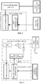
- Fig. 1 shows a schematic diagram of a fingerprint module applied to a smartphone
- Fig. 2 is a schematic block diagram of a fingerprint module.
- the fingerprint module specifically includes a fingerprint sensor, a metal decorative part, a touch detection circuit and a processing unit.
- the fingerprint module is provided in the lower area of a screen 111 of the smart phone.
- a metal decorative part 112 and a fingerprint sensor 113 are provided on a surface of the smart phone, and the metal decorative part 112 surrounds the fingerprint sensor 113 to protect and decorate the fingerprint sensor 113; the metal decorative part 112 on the smart phone is generally annular, and matches with a shape of the fingerprint sensor 113.
- the fingerprint sensor 113 includes a sensing electrode and a protective layer, and the protective layer is in direct contact with a user's finger.
- the touch detection circuit is connected to the metal decorative part; the processing unit is connected to the touch detection circuit and the fingerprint sensor.
- the processing unit in the present embodiment includes a microprocessor and a fingerprint recognition chip, the fingerprint recognition chip is connected to the fingerprint sensor, and the microprocessor is connected to the touch detection circuit and the fingerprint recognition chip.
- the microprocessor and the fingerprint recognition chip can be classified as a processing unit according to their functions in the present embodiment.
- the fingerprint recognition chip, the fingerprint sensor, and the metal decorative part can be a ready-made component (i.e., an existing fingerprint module).
- an existing fingerprint chip i.e., no change is made to the existing fingerprint chip
- the newly added touch detection circuit and microprocessor is combined with the newly added touch detection circuit and microprocessor to achieve all processing functions of the fingerprint module, thereby being easier to make and having a shorter manufacturing cycle.
- the fingerprint module of the present embodiment operates as follows. A user's finger touches the fingerprint module, and if the metal decorative part is touched, the touch detection circuit generates a first trigger signal. If the fingerprint sensor is touched, the fingerprint sensor generates a fingerprint sensing signal, and the fingerprint recognition chip generates a second trigger signal based on the fingerprint sensing signal. When the microprocessor receives at least one of the first trigger signal and the second trigger signal, the microprocessor generates a finger touch signal, which indicates that the touch operation of the user's finger is sensed.
- the microprocessor can generate a finger touch signal, as long as any of the sensor area and the metal decorative part of the fingerprint sensor is touched, perhaps due to differences in finger size or touch position. That is, the metal decorative part and the fingerprint sensor are cooperatively used for performing a joint detection, and an overall detection range of the fingerprint module is increased, thereby reducing the detection blind area of a finger and improving the detection accuracy of the fingerprint module for realizing a touch detection function.
- the touch detection circuit in the present embodiment specifically includes a driving signal source, a driving resistor R, an operational amplifier F, and an analog-to-digital converter ADC.
- the first input of the operational amplifier F is connected to the metal decorative part, and is connected to a driving signal source via the driving resistor R; the second input of the operational amplifier F is connected to a reference voltage Vcm; the first input of the operational amplifier F of the present embodiment is a negative phase input and the second input of the operational amplifier F of the present embodiment is a positive phase input.
- the input of the analog-to-digital converter ADC is connected to an output of the operational amplifier F, and the output of the analog-to-digital converter ADC is connected to the microprocessor.
- the finger touch detection principle of the touch detection circuit in the present embodiment is as follows.
- Us is a voltage amplitude of the driving voltage
- f is a frequency of the driving voltage
- X c is a reactance of the capacitor C 0
- C 0 is a capacitance of the metal decorative part with respect to the ground GND.
- X' c is a reactance of the capacitor C 0 when the metal decorative part is touched.
- the operational amplifier F amplifies the voltage at point A, and the amplified voltage is sampled by the analog-to-digital converter ADC and then is transmitted to the microprocessor, the microprocessor calculates the voltage at point A and determines whether the metal decorative part is touched according to variation of the voltage at point A.
- the driving signal source can be connected to the microprocessor, and the driving signal source can be switched on or off under control of the microprocessor.
- the microprocessor sets the output voltage of the driving signal source to zero, thus avoiding a crosstalk caused by coupling between the driving signal source and the sensing electrode.
- a second embodiment of the present application relates to a fingerprint module as shown in Fig. 4 .
- Another example of a touch detection circuit is provided in the fingerprint module of the second embodiment.
- the touch detection circuit includes a voltage source Vs, a first switch SW1, a second switch SW2, a third switch SW3, a capacitor C 1 , an operational amplifier F, and an analog-to-digital converter ADC.
- the first switch SW1 is connected between the metal decorative part and a first input of the operational amplifier F.
- the second switch SW2 is connected between the metal decorative part and the voltage source Vs.
- the third switch SW3 is connected in parallel with the capacitor C 1 between the first input of the operational amplifier F and an output of the operational amplifier F.A second input of the operational amplifier F is connected to the reference voltage Vcm.
- the first input of the operational amplifier F in the present embodiment is a negative phase input
- the second input of the operational amplifier F in the present embodiment is a positive phase input
- An input of the analog-to-digital converter ADC is connected to an output of the operational amplifier F, and an output of the analog-to-digital converter ADC is connected to the microprocessor; and control terminals of the first switch SW1, the second switch SW2 and the third switch SW3 respectively receive control signals to realize switching on and off.
- the touch detection circuit in the present embodiment can further include a timing circuit unit.
- the timing circuit unit includes three control terminals which are connected to the control terminals of the first switch SW1, the second switch SW2, and the third switch SW3, respectively; that is, the timing circuit unit performs timing control on switching on and switching off the first switch SW1, the second switch SW2, and the third switch SW3.
- the output voltage of the operational amplifier F has a variation ⁇ U.
- the Co When the metal decorative part is touched, the Co will be increased according to the description in the first embodiment, and the output voltage of the operational amplifier F will be changed according to the formula in step 5.
- the output voltage of the operational amplifier F is sampled by the analog-to-digital converter ADC and then is transmitted to the microprocessor.
- the microprocessor calculates the value of the voltage at point B and determines whether the metal decorative part is touched according to the change of the voltage at the point B.
- a third embodiment of the present application relates to a fingerprint module as shown in Fig. 5 .
- the third embodiment is substantially the same as the first or second embodiment, the main difference is that the processing unit of the first or second embodiment includes a microprocessor and a fingerprint recognition chip.
- the processing unit of the present embodiment includes a fingerprint recognition chip connected to a touch detection circuit and a fingerprint sensor.
- the fingerprint recognition chip generates a finger touch signal when the first trigger signal generated by the touch detection circuit and/or the fingerprint sensing signal generated by the fingerprint sensor is received by the fingerprint recognition chip.
- other processing functions can be realized by only changing software on the fingerprint chip; and, the touch detection circuit and the fingerprint recognition chip can be integrated together and can be packaged into one piece.
- a space for arranging elements can be saved, and it is advantageous for the miniaturization of intelligent terminal equipment.
- a fourth embodiment of the present application relates to a touch detection circuit, and the touch detection circuit in the present embodiment is a touch detection circuit in the first embodiment.
- a fifth embodiment of the present application relates to a touch detection circuit, and the touch detection circuit in the present embodiment is a touch detection circuit in the second embodiment.
- a sixth embodiment of the present application relates to a control method of fingerprint module.
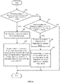
- the specific process is shown in Fig. 6 .
- the control method of fingerprint module includes:
- Step S100 The processing unit determines whether a received signal is a touch operation signal. If yes, the process proceeds to step 101. If no, the process proceeds to step 103.
- step S100 is executed by the fingerprint recognition chip.
- step S100 is executed by the microprocessor.
- Step S101 The processing unit is switched to a touch detection mode.
- t step S101 is executed by the fingerprint recognition chip.
- step S101 is executed by the microprocessor and the fingerprint recognition chip simultaneously. That is, the microprocessor and the fingerprint recognition chip are switched to the touch detection mode respectively.
- Step S102 In the touch detection mode, the processing unit generates a finger touch signal when a first trigger signal generated by the touch detection circuit and/or a fingerprint sensing signal generated by the fingerprint sensor is received by the processing unit.
- the processing unit includes a fingerprint recognition chip
- the fingerprint sensing signal generated by the fingerprint sensor is received by the fingerprint recognition chip.
- the fingerprint recognition chip generates a finger touch signal when the first trigger signal generated by the touch detection circuit and/or the fingerprint sensing signal generated by the fingerprint sensor is received by the fingerprint recognition chip.
- the processing unit includes a microprocessor and a fingerprint recognition chip
- the second trigger signal is generated according to the fingerprint sensing signal when the fingerprint sensing signal generated by the fingerprint sensor is received by the fingerprint recognition chip.
- the microprocessor generates a finger touch signal when the first trigger signal generated by the touch detection circuit and/or the second trigger signal generated by the fingerprint recognition chip is received by the microprocessor.
- Step S103 The processing unit determines whether or not the received signal is a fingerprint operation signal. If yes, the process proceeds to step 104, if no, the process is ended.
- step S103 is executed by the fingerprint recognition chip.
- step S103 is executed by the microprocessor.
- Step S104 The processing unit is switched to the fingerprint recognition mode.
- step S104 is executed by the fingerprint recognition chip.
- step S104 is executed by the microprocessor and the fingerprint recognition chip simultaneously. That is, the microprocessor and the fingerprint recognition chip are switched to the touch detection mode respectively.
- Step S105 In the fingerprint recognition mode, the processing unit receives the fingerprint sensing signal generated by the fingerprint sensor and generates a fingerprint image signal.
- the processing unit includes a fingerprint recognition chip
- the fingerprint recognition chip receives the fingerprint sensing signal generated by the fingerprint sensor and generates a fingerprint image signal. Then, the fingerprint recognition chip transmits the fingerprint image signal to the main controller; the main controller is a main controller of an intelligent terminal device to which the fingerprint module is applied.
- the processing unit includes a microprocessor and a fingerprint recognition chip
- the fingerprint recognition chip receives the fingerprint sensing signal generated by the fingerprint sensor and generates a fingerprint image signal; and the fingerprint image signal is transmitted to the main controller through the microprocessor. That is, in the fingerprint recognition mode, the microprocessor operates only as a transmission channel, without performing any operation on the fingerprint image signals.
Landscapes
- Engineering & Computer Science (AREA)
- Theoretical Computer Science (AREA)
- Human Computer Interaction (AREA)
- Physics & Mathematics (AREA)
- General Physics & Mathematics (AREA)
- Multimedia (AREA)
- General Engineering & Computer Science (AREA)
- Image Input (AREA)
- Measurement Of The Respiration, Hearing Ability, Form, And Blood Characteristics Of Living Organisms (AREA)
Abstract
Description
- The present application relates to fingerprint recognition technologies, and more particularly to a touch detection circuit, a fingerprint module and a control method of the fingerprint module.
- Intelligent terminal equipment has been greatly popularized with the rapid development of mobile communication. The fingerprint recognition technology has extensively used in the field of intelligent terminal equipment.
- At present, a fingerprint module is usually arranged under a screen of the intelligent terminal equipment, and in addition to a fingerprint identification function, the fingerprint module also provide a touch detection function. That is, the fingerprint module can determine a touch event by judging whether or not a fingerprint of a user's finger is detected.
- However, due to a limited size of the intelligent terminal equipment, the fingerprint module is generally small, and a size of a fingerprint sensor thereof is usually smaller than that of a finger. If the finger is not in place, it is likely not to be detected. In other words, a finger detection blind area may exist, thereby decreasing the touch detection accuracy.
- An object of the present invention is to provide a touch detection circuit, a fingerprint module and a control method thereof. A metal decorative part and a fingerprint sensor are cooperatively used for performing a joint detection, which increases the overall detection range of the fingerprint module, and reduces the detection blind area of a finger, thereby improving the detection accuracy of the fingerprint module for realizing a touch detection function.
- To solve the above technical problems, some embodiments of the present application provide a fingerprint module including: a fingerprint sensor, a metal decorative part, a touch detection circuit and a processing unit; the metal decorative part surrounds the fingerprint sensor; the touch detection circuit is connected to the metal decorative part; the touch detection circuit generates a first trigger signal when the metal decorative part is touched; the processing unit is connected to the touch detection circuit and the fingerprint sensor; wherein the processing unit generates a finger touch signal when the first trigger signal generated by the touch detection circuit and/or the fingerprint sensing signal generated by the fingerprint sensor is received.
- Some embodiments of the present application provide a touch detection circuit including: a driving signal source, a driving resistor, an operational amplifier, and an analog-to-digital converter; a first input of the operational amplifier is connected to the metal decorative part, the first input is further connected to the driving signal source via the driving resistor; an input of the analog-to-digital converter is connected to an output of the operational amplifier, and an output of the analog-to-digital converter is connected to the processing unit.
- Some embodiments of the present application provide a touch detection circuit including: a voltage source, a first switch, a second switch, a third switch, a capacitor, an operational amplifier, and an analog-to-digital converter, the first switch is connected between the metal decorative part and a first input of the operational amplifier, the second switch is connected between the metal decorative part and the voltage source; the third switch is connected in parallel with the capacitor between the first input of the operational amplifier and an output of the operational amplifier; an input of the analog-to-digital converter is connected to the output of the operational amplifier, an output of the analog-to-digital converter is connected to the processing unit; wherein the control terminals of the first switch, the second switch, and the third switch respectively receive a control signal to realize switching on and switching off.
- Some embodiments of the present application provide a control method of fingerprint module that is applied to the fingerprint module; the control method of fingerprint module includes: switching the processing unit to a touch detection mode when the touch operation signal is received by the processing unit; in the touch detection mode, generating by the processing unit a finger touch signal when a first trigger signal generated by the touch detection circuit and/or a fingerprint sensing signal generated by the fingerprint sensor is received by the processing unit; switching the processing unit to a fingerprint recognition mode when the fingerprint operation signal is received by the processing unit; in the fingerprint recognition mode, receiving by the processing unit the fingerprint sensing signal generated by the fingerprint sensor and generating by the processing unit a fingerprint image signal.
- Compared to the known techniques, in some embodiments of the present application the metal decorative part surrounds the fingerprint sensor; the touch detection circuit is connected to the metal decorative part; the touch detection circuit generates a first trigger signal when the metal decorative part is touched; the processing unit is connected to the touch detection circuit and the fingerprint sensor; the processing unit generates a finger touch signal when the first trigger signal generated by the touch detection circuit and/or the fingerprint sensing signal generated by the fingerprint sensor is received. In summary, a finger touch can be sensed when the metal decorative part is connected to the touch circuit, that is, the metal decorative part and the fingerprint sensor can be cooperatively used for performing a joint detection, which increases the overall detection range of the fingerprint module is increased, and reduces the detection blind area of a finger, thereby improving the detection accuracy of the fingerprint module for realizing a touch detection function.
- Additionally, the processing unit includes: a fingerprint recognition chip; the fingerprint recognition chip is connected to the touch detection circuit and the fingerprint sensor; wherein the fingerprint recognition chip generates the finger touch signal when the first trigger signal generated by the touch detection circuit and/or the fingerprint sensing signal generated by the fingerprint sensor is received. That is, other processing functions can be realized by only changing the software on the fingerprint chip; and, the touch detection circuit and the fingerprint recognition chip can be integrated together and can be packaged as a whole. Thus, the space for arranging elements can be saved, and it is advantageous for the miniaturization of intelligent terminal equipment.
- Additionally, the processing unit includes: a fingerprint recognition chip and a microprocessor; the fingerprint recognition chip is connected to the fingerprint sensor; the microprocessor is connected to the touch detection circuit and the fingerprint recognition chip; wherein the fingerprint recognition chip generates a second trigger signal when the fingerprint sensing signal is received; the microprocessor generates the finger touch signal when the first trigger signal and/or the second trigger signal is received. That is, a microprocessor for receiving the first trigger signal and/or the second trigger signal is added. Therefore, in the implementation of the present aspect, an existing fingerprint chip (i.e., no change is made to the existing fingerprint chip)is combined with a new added microprocessor to achieve all processing functions of the fingerprint module, thereby being easier to make and having a shorter manufacturing cycle.
- Additionally, the touch detection circuit includes: a driving signal source, a driving resistor, an operational amplifier, and an analog-to-digital converter; a first input of the operational amplifier is connected to the metal decorative part, the first input further is connected to the driving signal source via the driving resistor; an input of the analog-to-digital converter is connected to an output of the operational amplifier, and an output of the analog-to-digital converter is connected to the processing unit. As described above, a specific example of the touch detection circuit is provided.
- Additionally, the driving signal source is further connected to the processing unit; wherein the processing unit switches on or off the driving signal source. The driving signal source switches on or off under control of a microprocessor, and when the processing unit is in a fingerprint recognition mode, the microprocessor sets the output voltage of the driving signal source to zero, thus avoiding a crosstalk caused by the coupling between the driving signal source and a fingerprint sensing electrode.
- Additionally, the touch detection circuit includes a voltage source, a first switch, a second switch, a third switch, a capacitor, an operational amplifier, and an analog-to-digital converter; the first switch is connected between the metal decorative part and a first input of the operational amplifier, the second switch is connected between the metal decorative part and the voltage source; the third switch is connected in parallel with the capacitor between a first input of the operational amplifier and an output of the operational amplifier; an input of the analog-to-digital converter is connected to the output of the operational amplifier, an output of the analog-to-digital converter is connected to the processing unit; wherein the control terminals of the first switch, the second switch, and the third switch respectively receive a control signal to realize switching on and switching off. As described above, another specific implementation of the touch detection circuit is provided.
- Additionally, the touch detection circuit further includes: a timing circuit unit; the timing circuit unit includes three control terminals which are respectively connected to the control terminals of the first switch, the second switch, and the third switch. The timing circuit unit realizes control of the first switch, the second switch, and the third switch.
-
-
Fig. 1 is a schematic diagram of a fingerprint module applied to a smartphone according to a first embodiment of the present application; -
Fig. 2 is a schematic block diagram of a fingerprint module according to a first embodiment of the present application; -
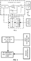
Fig. 3 is a specific schematic diagram of a touch detection circuit according to a first embodiment of the present application; -
Fig. 4 is a specific schematic diagram of a touch detection circuit according to a second embodiment of the present application; -
Fig. 5 is a schematic block diagram of a fingerprint module according to a third embodiment of the present application; and -
Fig.6 is a flowchart of a control method of fingerprint module according to a sixth embodiment of the present application. - To make the purposes, technical aspects and advantages of the present invention more clear, embodiments of the present application will be described in detail with reference to the accompanying drawings. However, it will be understood by those skilled in the art that many technical details have been presented in various embodiments of the present application in order to provide a better understanding of the present application. However, the technical solutions as claimed by the present application may be implemented without these technical details and variations and modifications based on the following embodiments.
- A first embodiment of the present application relates to a fingerprint module that is applied toa smart terminal equipment, such as a smartphone.
Fig. 1 shows a schematic diagram of a fingerprint module applied to a smartphone,Fig. 2 is a schematic block diagram of a fingerprint module. Referring toFigs. 1 and2 , the fingerprint module specifically includes a fingerprint sensor, a metal decorative part, a touch detection circuit and a processing unit. - As shown in
Fig. 1 , the fingerprint module is provided in the lower area of ascreen 111 of the smart phone. A metaldecorative part 112 and afingerprint sensor 113 are provided on a surface of the smart phone, and the metaldecorative part 112 surrounds thefingerprint sensor 113 to protect and decorate thefingerprint sensor 113; the metaldecorative part 112 on the smart phone is generally annular, and matches with a shape of thefingerprint sensor 113. In the present embodiment, thefingerprint sensor 113 includes a sensing electrode and a protective layer, and the protective layer is in direct contact with a user's finger. - As shown in
Fig. 2 , the touch detection circuit is connected to the metal decorative part; the processing unit is connected to the touch detection circuit and the fingerprint sensor. Specifically, the processing unit in the present embodiment includes a microprocessor and a fingerprint recognition chip, the fingerprint recognition chip is connected to the fingerprint sensor, and the microprocessor is connected to the touch detection circuit and the fingerprint recognition chip. - It should be noted that the microprocessor and the fingerprint recognition chip can be classified as a processing unit according to their functions in the present embodiment. In fact, the fingerprint recognition chip, the fingerprint sensor, and the metal decorative part can be a ready-made component (i.e., an existing fingerprint module).Accordingly, in the present embodiment, a touch detection circuit and a microprocessor (which cooperatively constitute an auxiliary chip) are actually newly added. That is, in the present embodiment, an existing fingerprint chip (i.e., no change is made to the existing fingerprint chip)is combined with the newly added touch detection circuit and microprocessor to achieve all processing functions of the fingerprint module, thereby being easier to make and having a shorter manufacturing cycle.
- The fingerprint module of the present embodiment operates as follows. A user's finger touches the fingerprint module, and if the metal decorative part is touched, the touch detection circuit generates a first trigger signal. If the fingerprint sensor is touched, the fingerprint sensor generates a fingerprint sensing signal, and the fingerprint recognition chip generates a second trigger signal based on the fingerprint sensing signal. When the microprocessor receives at least one of the first trigger signal and the second trigger signal, the microprocessor generates a finger touch signal, which indicates that the touch operation of the user's finger is sensed.
- Therefore, when a touch operation is performed by a user, the microprocessor can generate a finger touch signal, as long as any of the sensor area and the metal decorative part of the fingerprint sensor is touched, perhaps due to differences in finger size or touch position. That is, the metal decorative part and the fingerprint sensor are cooperatively used for performing a joint detection, and an overall detection range of the fingerprint module is increased, thereby reducing the detection blind area of a finger and improving the detection accuracy of the fingerprint module for realizing a touch detection function.
- As shown in
Fig. 3 , the touch detection circuit in the present embodiment specifically includes a driving signal source, a driving resistor R, an operational amplifier F, and an analog-to-digital converter ADC. The first input of the operational amplifier F is connected to the metal decorative part, and is connected to a driving signal source via the driving resistor R; the second input of the operational amplifier F is connected to a reference voltage Vcm; the first input of the operational amplifier F of the present embodiment is a negative phase input and the second input of the operational amplifier F of the present embodiment is a positive phase input. The input of the analog-to-digital converter ADC is connected to an output of the operational amplifier F, and the output of the analog-to-digital converter ADC is connected to the microprocessor. - The finger touch detection principle of the touch detection circuit in the present embodiment is as follows.
- When the metal decorative part is not touched by a finger, the driving resistor R and the parasitic capacitance C0 of the metal decorative part with respect to the ground GND divide a driving voltage output by the driving signal source, and a voltage at point A (i.e., the first input of the operational amplifier F) is:

- In the above formula, Us is a voltage amplitude of the driving voltage, f is a frequency of the driving voltage, Xc is a reactance of the capacitor C0, and C0 is a capacitance of the metal decorative part with respect to the ground GND.
- Since a parasitic capacitance ΔC also exists between the finger and the ground, when the metal decorative part is touched, ΔC and C0 are in parallel, and the voltage at point A becomes:

- In the above formula, X'c is a reactance of the capacitor C0 when the metal decorative part is touched.
- It can be seen that the voltage at point A becomes smaller when the metal decorative part is touched. The operational amplifier F amplifies the voltage at point A, and the amplified voltage is sampled by the analog-to-digital converter ADC and then is transmitted to the microprocessor, the microprocessor calculates the voltage at point A and determines whether the metal decorative part is touched according to variation of the voltage at point A.
- Preferably, the driving signal source can be connected to the microprocessor, and the driving signal source can be switched on or off under control of the microprocessor. When the processing unit is in a fingerprint recognition mode, the microprocessor sets the output voltage of the driving signal source to zero, thus avoiding a crosstalk caused by coupling between the driving signal source and the sensing electrode.
- A second embodiment of the present application relates to a fingerprint module as shown in
Fig. 4 . Another example of a touch detection circuit is provided in the fingerprint module of the second embodiment. The touch detection circuit includes a voltage source Vs, a first switch SW1, a second switch SW2, a third switch SW3, a capacitor C1, an operational amplifier F, and an analog-to-digital converter ADC. The first switch SW1 is connected between the metal decorative part and a first input of the operational amplifier F. The second switch SW2 is connected between the metal decorative part and the voltage source Vs. The third switch SW3 is connected in parallel with the capacitor C1 between the first input of the operational amplifier F and an output of the operational amplifier F.A second input of the operational amplifier F is connected to the reference voltage Vcm. The first input of the operational amplifier F in the present embodiment is a negative phase input, and the second input of the operational amplifier F in the present embodiment is a positive phase input. An input of the analog-to-digital converter ADC is connected to an output of the operational amplifier F, and an output of the analog-to-digital converter ADC is connected to the microprocessor; and control terminals of the first switch SW1, the second switch SW2 and the third switch SW3 respectively receive control signals to realize switching on and off. - Preferably, the touch detection circuit in the present embodiment can further include a timing circuit unit. The timing circuit unit includes three control terminals which are connected to the control terminals of the first switch SW1, the second switch SW2, and the third switch SW3, respectively; that is, the timing circuit unit performs timing control on switching on and switching off the first switch SW1, the second switch SW2, and the third switch SW3.
- A finger touch detection method of the touch detection circuit in the present embodiment can includes the following steps:
- Step 1: When the touch detection circuit is not in operation, the third switch SW3 is switched on, the first switch SW1 is switched off, and the second switch SW2 is also switched on; an output voltage of the operational amplifier F is Vcm (i.e., the output voltage of the operational amplifier F is equal to the reference voltage).
- Step 2: When the touch detection circuit starts to operate, the third switch SW3 is switched off.
- Step 3: When SW2 is switched on, the voltage at point B is Vs.
- Step 4: When SW1 is switched on, due to Vs≠Vcm, the capacitance Co of the metal decorative part with respect to the ground GND discharges to capacitor C1 until a voltage at point B is equal to Vcm. In the discharge process, the charge of C0 shifts to C1 such that the voltages at both ends of C1 change, and the following relationship is met:
- Since the voltage at point B is stabilized to Vcm, the output voltage of the operational amplifier F has a variation Δ U.
- Step 5: steps 3, 4 are repeatedly performed for N times (N can be set to any integer greater than 0) and the output voltage of the operational amplifier F is:

- When the metal decorative part is touched, the Co will be increased according to the description in the first embodiment, and the output voltage of the operational amplifier F will be changed according to the formula in step 5.The output voltage of the operational amplifier F is sampled by the analog-to-digital converter ADC and then is transmitted to the microprocessor. The microprocessor calculates the value of the voltage at point B and determines whether the metal decorative part is touched according to the change of the voltage at the point B.
- A third embodiment of the present application relates to a fingerprint module as shown in
Fig. 5 . The third embodiment is substantially the same as the first or second embodiment, the main difference is that the processing unit of the first or second embodiment includes a microprocessor and a fingerprint recognition chip. The processing unit of the present embodiment includes a fingerprint recognition chip connected to a touch detection circuit and a fingerprint sensor. - In the present embodiment, the fingerprint recognition chip generates a finger touch signal when the first trigger signal generated by the touch detection circuit and/or the fingerprint sensing signal generated by the fingerprint sensor is received by the fingerprint recognition chip.
- In the present embodiment, other processing functions can be realized by only changing software on the fingerprint chip; and, the touch detection circuit and the fingerprint recognition chip can be integrated together and can be packaged into one piece. Thus, a space for arranging elements can be saved, and it is advantageous for the miniaturization of intelligent terminal equipment.
- A fourth embodiment of the present application relates to a touch detection circuit, and the touch detection circuit in the present embodiment is a touch detection circuit in the first embodiment.
- A fifth embodiment of the present application relates to a touch detection circuit, and the touch detection circuit in the present embodiment is a touch detection circuit in the second embodiment.
- A sixth embodiment of the present application relates to a control method of fingerprint module. The specific process is shown in
Fig. 6 . The control method of fingerprint module includes: - Step S100: The processing unit determines whether a received signal is a touch operation signal. If yes, the process proceeds to step 101. If no, the process proceeds to step 103.
- If the processing unit includes a fingerprint recognition chip, step S100 is executed by the fingerprint recognition chip.
- If the processing unit includes a microprocessor and a fingerprint recognition chip, step S100 is executed by the microprocessor.
- Step S101: The processing unit is switched to a touch detection mode.
- If the processing unit includes a fingerprint recognition chip, t step S101 is executed by the fingerprint recognition chip.
- If the processing unit includes a microprocessor and a fingerprint recognition chip, step S101 is executed by the microprocessor and the fingerprint recognition chip simultaneously. That is, the microprocessor and the fingerprint recognition chip are switched to the touch detection mode respectively.
- Step S102: In the touch detection mode, the processing unit generates a finger touch signal when a first trigger signal generated by the touch detection circuit and/or a fingerprint sensing signal generated by the fingerprint sensor is received by the processing unit.
- If the processing unit includes a fingerprint recognition chip, the fingerprint sensing signal generated by the fingerprint sensor is received by the fingerprint recognition chip. The fingerprint recognition chip generates a finger touch signal when the first trigger signal generated by the touch detection circuit and/or the fingerprint sensing signal generated by the fingerprint sensor is received by the fingerprint recognition chip.
- If the processing unit includes a microprocessor and a fingerprint recognition chip, the second trigger signal is generated according to the fingerprint sensing signal when the fingerprint sensing signal generated by the fingerprint sensor is received by the fingerprint recognition chip. The microprocessor generates a finger touch signal when the first trigger signal generated by the touch detection circuit and/or the second trigger signal generated by the fingerprint recognition chip is received by the microprocessor.
- Step S103: The processing unit determines whether or not the received signal is a fingerprint operation signal. If yes, the process proceeds to step 104, if no, the process is ended.
- If the processing unit includes a fingerprint recognition chip, step S103 is executed by the fingerprint recognition chip.
- If the processing unit includes a microprocessor and a fingerprint recognition chip, step S103 is executed by the microprocessor.
- Step S104: The processing unit is switched to the fingerprint recognition mode.
- If the processing unit includes a fingerprint recognition chip, step S104 is executed by the fingerprint recognition chip.
- If the processing unit includes a microprocessor and a fingerprint recognition chip, step S104 is executed by the microprocessor and the fingerprint recognition chip simultaneously. That is, the microprocessor and the fingerprint recognition chip are switched to the touch detection mode respectively.
- Step S105: In the fingerprint recognition mode, the processing unit receives the fingerprint sensing signal generated by the fingerprint sensor and generates a fingerprint image signal.
- If the processing unit includes a fingerprint recognition chip, the fingerprint recognition chip receives the fingerprint sensing signal generated by the fingerprint sensor and generates a fingerprint image signal. Then, the fingerprint recognition chip transmits the fingerprint image signal to the main controller; the main controller is a main controller of an intelligent terminal device to which the fingerprint module is applied.
- If the processing unit includes a microprocessor and a fingerprint recognition chip, the fingerprint recognition chip receives the fingerprint sensing signal generated by the fingerprint sensor and generates a fingerprint image signal; and the fingerprint image signal is transmitted to the main controller through the microprocessor. That is, in the fingerprint recognition mode, the microprocessor operates only as a transmission channel, without performing any operation on the fingerprint image signals.
- The steps of the above methods are only for the sake of clarity of the description. The steps may be combined into one step or some steps may be divided into a plurality of steps, which shall fall within the scope of the present invention as long as a same logical relationship is included. All insignificant modifications to the algorithm or the process or the introduction of insignificant designs and the core design without changing the algorithm and process fall within the scope of the present invention.
- The above-described exemplary embodiments explain the objectives, technical solutions and advantages of the present application in details, and it should be understood that the foregoing description is only the exemplary embodiments of the present application and is not intended to limit the scope of the present invention. Any modifications, equivalent substitutions, improvements, and the like that fall within the spirit and scope of the present invention are intended to be included in the scope of the present invention.

Claims (10)
- A fingerprint module, characterized in that the fingerprint module comprises:a fingerprint sensor, a metal decorative part, a touch detection circuit and a processing unit;wherein the metal decorative part surrounds the fingerprint sensor;wherein the touch detection circuit is connected to the metal decorative part, the touch detection circuit is configured to generate a first trigger signal when the metal decorative part is touched;wherein the processing unit is connected to the touch detection circuit and the fingerprint sensor, the processing unit is configured to generate a finger touch signal when the first trigger signal generated by the touch detection circuit and/or the fingerprint sensing signal generated by the fingerprint sensor is received.
- The fingerprint module according to claim 1, characterized in that the processing unit comprises a fingerprint recognition chip, the fingerprint recognition chip is connected to the touch detection circuit and the fingerprint sensor;
wherein the fingerprint recognition chip is configured to generate the finger touch signal when the first trigger signal generated by the touch detection circuit and/or the fingerprint sensing signal generated by the fingerprint sensor is received. - The fingerprint module according to claim 1, characterized in that the processing unit comprises:A fingerprint recognition chip and a microprocessor;wherein the fingerprint recognition chip is connected to the fingerprint sensor, the microprocessor is connected to the touch detection circuit and the fingerprint recognition chip;wherein the fingerprint recognition chip is configured to generate a second trigger signal when the fingerprint sensing signal is received;the microprocessor is configured to generate the finger touch signal when the first trigger signal and/or the second trigger signal is received.
- The fingerprint module according to claim 1, characterized in that the touch detection circuit comprises: a driving signal source, a driving resistor, an operational amplifier, and an analog-to-digital converter;
Wherein a first input of the operational amplifier is connected to the metal decorative part, the first input being further connected to the driving signal source via the driving resistor;
an input of the analog-to-digital converter is connected to an output of the operational amplifier, and an output of the analog-to-digital converter is connected to the processing unit. - The fingerprint module according to claim 4, characterized in that the driving signal source is further connected to the processing unit; wherein the processing unit is configured to switch on or off the driving signal source.
- The fingerprint module according to claim 1, characterized in that the touch detection circuit comprises: a voltage source, a first switch, a second switch, a third switch, a capacitor, an operational amplifier, and an analog-to-digital converter;
wherein the first switch is connected between the metal decorative part and a first input of the operational amplifier, the second switch is connected between the metal decorative part and the voltage source;
the third switch is connected in parallel with the capacitor between the first input of the operational amplifier and an output of the operational amplifier;
an input of the analog-to-digital converter is connected to the output of the operational amplifier, an output of the analog-to-digital converter is connected to the processing unit;
the control terminals of the first switch, the second switch, and the third switch respectively receive a control signal for switching on and switching off. - The fingerprint module according to claim 6, characterized in that the touch detection circuit further comprises a timing circuit unit;
wherein the timing circuit unit includes three control terminals which are respectively connected to the control terminals of the first switch, the second switch, and the third switch. - A touch detection circuit, characterized in that the touch detection circuit is the touch detection circuit in the fingerprint module according to claim 4 or 5.
- A touch detection circuit, characterized in that the touch detection circuit is the touch detection circuit in the fingerprint module according to claim 6 or 7.
- A control method of a fingerprint module, characterized in that the control method is applied to a fingerprint module according to any one of claims 1 to 7, the control method of the fingerprint module comprising:Switching a processing unit to a touch detection mode when a touch operation signal is received by the processing unit;in the touch detection mode, generating, by the processing unit, a finger touch signal when a first trigger signal generated by a touch detection circuit and/or a fingerprint sensing signal generated by a fingerprint sensor is received by the processing unit;switching the processing unit to a fingerprint recognition mode when a fingerprint operation signal is received by the processing unit;in the fingerprint recognition mode, receiving, by the processing unit, the fingerprint sensing signal generated by the fingerprint sensor and generating a fingerprint image signal.
Applications Claiming Priority (1)
| Application Number | Priority Date | Filing Date | Title |
|---|---|---|---|
| PCT/CN2016/085613 WO2017214820A1 (en) | 2016-06-13 | 2016-06-13 | Touch detection circuit, fingerprint module and control method thereof |
Publications (2)
| Publication Number | Publication Date |
|---|---|
| EP3285204A1 true EP3285204A1 (en) | 2018-02-21 |
| EP3285204A4 EP3285204A4 (en) | 2018-05-30 |
Family
ID=58215919
Family Applications (1)
| Application Number | Title | Priority Date | Filing Date |
|---|---|---|---|
| EP16892937.0A Withdrawn EP3285204A4 (en) | 2016-06-13 | 2016-06-13 | Touch detection circuit, fingerprint module and control method thereof |
Country Status (4)
| Country | Link |
|---|---|
| EP (1) | EP3285204A4 (en) |
| KR (1) | KR20180014682A (en) |
| CN (1) | CN106462751A (en) |
| WO (1) | WO2017214820A1 (en) |
Families Citing this family (9)
| Publication number | Priority date | Publication date | Assignee | Title |
|---|---|---|---|---|
| CN106462751A (en) * | 2016-06-13 | 2017-02-22 | 深圳市汇顶科技股份有限公司 | Touch detection circuit, fingerprint module and its control method |
| CN106959877B (en) * | 2017-03-31 | 2020-07-10 | 浙江中正智能科技有限公司 | Fingerprint identification chip driving circuit, fingerprint identification chip driving method and device |
| CN108427518B (en) * | 2018-02-13 | 2020-12-25 | 上海摩软通讯技术有限公司 | Terminal input assembly, terminal and terminal input method |
| KR20180058669A (en) | 2018-03-28 | 2018-06-01 | 한국전자통신연구원 | Method for recognizing things and communicating with things automatically |
| CN109379073A (en) * | 2018-10-29 | 2019-02-22 | 努比亚技术有限公司 | Touch key-press detection circuit and its processing method, terminal, storage medium |
| CN112986955A (en) * | 2019-12-17 | 2021-06-18 | 北京小米移动软件有限公司 | Proximity sensor and electronic device |
| CN113920551B (en) * | 2021-09-30 | 2023-02-07 | 深圳市汇顶科技股份有限公司 | Ultrasonic image sensor and related electronic device |
| EP4394625A4 (en) | 2021-09-30 | 2024-09-18 | Huike (Singapore) Holding Pte.Ltd. | ULTRASONIC IMAGE SENSOR AND RELATED ELECTRONIC DEVICE |
| CN116363707A (en) * | 2023-02-27 | 2023-06-30 | 深圳芯启航科技有限公司 | Fingerprint identification system and method |
Family Cites Families (14)
| Publication number | Priority date | Publication date | Assignee | Title |
|---|---|---|---|---|
| JP4036798B2 (en) * | 2003-07-29 | 2008-01-23 | アルプス電気株式会社 | Capacitance detection circuit, detection method, and fingerprint sensor |
| US9740343B2 (en) * | 2012-04-13 | 2017-08-22 | Apple Inc. | Capacitive sensing array modulation |
| CN103745194B (en) * | 2013-12-20 | 2017-11-28 | 深圳市汇顶科技股份有限公司 | Finger print detection device and mobile terminal |
| CN103902971A (en) * | 2014-03-12 | 2014-07-02 | 深圳市汇顶科技股份有限公司 | Fingerprint detection circuit and fingerprint detection device |
| CN103942538B (en) * | 2014-04-04 | 2017-06-06 | 南昌欧菲生物识别技术有限公司 | Fingerprint Identification sensor encapsulating structure |
| KR20150144937A (en) * | 2014-06-18 | 2015-12-29 | (주)파트론 | Fingerprint sensor module |
| KR101881682B1 (en) * | 2014-10-13 | 2018-07-24 | 선전 구딕스 테크놀로지 컴퍼니, 리미티드 | Sensor pixel circuitry for fingerprint identification |
| KR101659492B1 (en) * | 2014-11-10 | 2016-09-23 | 한신대학교 산학협력단 | Charge Transfer Circuit for Capacitive Sensing and Apparatus For Detecting Fingerprint Having Thereof |
| CN104318222B (en) * | 2014-11-14 | 2019-10-11 | 深圳市汇顶科技股份有限公司 | Detection method and device for fingerprint detection |
| CN104794433A (en) * | 2015-03-27 | 2015-07-22 | 深圳市汇顶科技股份有限公司 | Fingerprint recognition system and fingerprint recognition method |
| CN105117684B (en) * | 2015-07-27 | 2017-04-19 | 深圳市汇顶科技股份有限公司 | Fingerprint detection circuit and fingerprint identification system |
| CN205121587U (en) * | 2015-11-09 | 2016-03-30 | 深圳市汇顶科技股份有限公司 | Fingerprint sensing device and terminal equipment |
| CN105512650B (en) * | 2016-01-26 | 2019-10-25 | 湖南融创微电子有限公司 | A capacitive fingerprint detection circuit, sensor and device |
| CN106462751A (en) * | 2016-06-13 | 2017-02-22 | 深圳市汇顶科技股份有限公司 | Touch detection circuit, fingerprint module and its control method |
-
2016
- 2016-06-13 CN CN201680000665.XA patent/CN106462751A/en active Pending
- 2016-06-13 EP EP16892937.0A patent/EP3285204A4/en not_active Withdrawn
- 2016-06-13 WO PCT/CN2016/085613 patent/WO2017214820A1/en not_active Ceased
- 2016-06-13 KR KR1020177026732A patent/KR20180014682A/en not_active Ceased
Also Published As
| Publication number | Publication date |
|---|---|
| WO2017214820A1 (en) | 2017-12-21 |
| KR20180014682A (en) | 2018-02-09 |
| EP3285204A4 (en) | 2018-05-30 |
| CN106462751A (en) | 2017-02-22 |
Similar Documents
| Publication | Publication Date | Title |
|---|---|---|
| US20180005004A1 (en) | Touch detection circuit, fingerprint module and control method thereof | |
| EP3640779B1 (en) | Capacitance detection circuit, touch chip and electronic device | |
| US10845926B2 (en) | Capacitance detecting circuit, touch device and terminal device | |
| US9870097B2 (en) | Noise cancellation technique for capacitive touchscreen controller using differential sensing | |
| EP3595175B1 (en) | Proximity sensor and mobile wireless device | |
| EP1623313B1 (en) | Capacitive object sensing system and corresponding method | |
| US9182872B2 (en) | Indicator position detecting device | |
| KR20180014682A (en) | Touch detection circuit, fingerprint module and control method thereof | |
| US11275468B2 (en) | Capacitance detection circuit, touch control chip and electronic device | |
| US20190278401A1 (en) | Capacitance detecting circuit, touch detecting device and terminal device | |
| EP4080336B1 (en) | Detection circuit, touch panel, and electronic device | |
| CN110596465B (en) | Capacitance detection circuit, touch device and terminal equipment | |
| KR20190038187A (en) | Apparatus and method for detecting touch | |
| CN111600590A (en) | Capacitance detection circuit and touch chip | |
| JP2017525004A (en) | Electronic device with fingerprint sensing system and conductive housing | |
| US11206019B2 (en) | Capacitance detection circuit, capacitance detection method, touch chip, and electronic device | |
| KR20170052051A (en) | Touch sensing method, touch sensing controller and touch sensing device having the same | |
| US11686753B2 (en) | Capacitance detection method and circuit | |
| CN214473623U (en) | Capacitance detection circuit | |
| EP3236341B1 (en) | Touch screen driving method, touch screen, and display device | |
| KR101844848B1 (en) | Touch Detection Method and Touch Detection Apparatus | |
| EP4293910A1 (en) | Proximity sensor and antenna | |
| TW201800924A (en) | Semiconductor device, position detection device, and control method of semiconductor device | |
| US10044336B2 (en) | Apparatus for preventing noise in electronic device |
Legal Events
| Date | Code | Title | Description |
|---|---|---|---|
| PUAI | Public reference made under article 153(3) epc to a published international application that has entered the european phase |
Free format text: ORIGINAL CODE: 0009012 |
|
| 17P | Request for examination filed |
Effective date: 20170914 |
|
| AK | Designated contracting states |
Kind code of ref document: A1 Designated state(s): AL AT BE BG CH CY CZ DE DK EE ES FI FR GB GR HR HU IE IS IT LI LT LU LV MC MK MT NL NO PL PT RO RS SE SI SK SM TR |
|
| AX | Request for extension of the european patent |
Extension state: BA ME |
|
| A4 | Supplementary search report drawn up and despatched |
Effective date: 20180504 |
|
| RIC1 | Information provided on ipc code assigned before grant |
Ipc: G06K 9/00 20060101AFI20180426BHEP Ipc: G06F 3/044 20060101ALI20180426BHEP |
|
| 17Q | First examination report despatched |
Effective date: 20190122 |
|
| STAA | Information on the status of an ep patent application or granted ep patent |
Free format text: STATUS: THE APPLICATION HAS BEEN WITHDRAWN |
|
| 18W | Application withdrawn |
Effective date: 20190506 |