EP3285118A1 - Ecran muni de microstructures rétroréfléchissantes - Google Patents
Ecran muni de microstructures rétroréfléchissantes Download PDFInfo
- Publication number
- EP3285118A1 EP3285118A1 EP17192509.2A EP17192509A EP3285118A1 EP 3285118 A1 EP3285118 A1 EP 3285118A1 EP 17192509 A EP17192509 A EP 17192509A EP 3285118 A1 EP3285118 A1 EP 3285118A1
- Authority
- EP
- European Patent Office
- Prior art keywords
- screen
- face
- film
- mold
- retroreflective
- Prior art date
- Legal status (The legal status is an assumption and is not a legal conclusion. Google has not performed a legal analysis and makes no representation as to the accuracy of the status listed.)
- Granted
Links
Images



Classifications
-
- G—PHYSICS
- G02—OPTICS
- G02B—OPTICAL ELEMENTS, SYSTEMS OR APPARATUS
- G02B27/00—Optical systems or apparatus not provided for by any of the groups G02B1/00 - G02B26/00, G02B30/00
- G02B27/01—Head-up displays
- G02B27/0101—Head-up displays characterised by optical features
-
- B—PERFORMING OPERATIONS; TRANSPORTING
- B29—WORKING OF PLASTICS; WORKING OF SUBSTANCES IN A PLASTIC STATE IN GENERAL
- B29C—SHAPING OR JOINING OF PLASTICS; SHAPING OF MATERIAL IN A PLASTIC STATE, NOT OTHERWISE PROVIDED FOR; AFTER-TREATMENT OF THE SHAPED PRODUCTS, e.g. REPAIRING
- B29C33/00—Moulds or cores; Details thereof or accessories therefor
- B29C33/38—Moulds or cores; Details thereof or accessories therefor characterised by the material or the manufacturing process
- B29C33/3842—Manufacturing moulds, e.g. shaping the mould surface by machining
-
- B—PERFORMING OPERATIONS; TRANSPORTING
- B29—WORKING OF PLASTICS; WORKING OF SUBSTANCES IN A PLASTIC STATE IN GENERAL
- B29C—SHAPING OR JOINING OF PLASTICS; SHAPING OF MATERIAL IN A PLASTIC STATE, NOT OTHERWISE PROVIDED FOR; AFTER-TREATMENT OF THE SHAPED PRODUCTS, e.g. REPAIRING
- B29C33/00—Moulds or cores; Details thereof or accessories therefor
- B29C33/42—Moulds or cores; Details thereof or accessories therefor characterised by the shape of the moulding surface, e.g. ribs or grooves
-
- B—PERFORMING OPERATIONS; TRANSPORTING
- B29—WORKING OF PLASTICS; WORKING OF SUBSTANCES IN A PLASTIC STATE IN GENERAL
- B29D—PRODUCING PARTICULAR ARTICLES FROM PLASTICS OR FROM SUBSTANCES IN A PLASTIC STATE
- B29D11/00—Producing optical elements, e.g. lenses or prisms
- B29D11/00605—Production of reflex reflectors
- B29D11/00625—Moulds for reflex reflectors
-
- G—PHYSICS
- G02—OPTICS
- G02B—OPTICAL ELEMENTS, SYSTEMS OR APPARATUS
- G02B27/00—Optical systems or apparatus not provided for by any of the groups G02B1/00 - G02B26/00, G02B30/00
- G02B27/01—Head-up displays
- G02B27/017—Head mounted
- G02B27/0172—Head mounted characterised by optical features
-
- G—PHYSICS
- G02—OPTICS
- G02B—OPTICAL ELEMENTS, SYSTEMS OR APPARATUS
- G02B5/00—Optical elements other than lenses
- G02B5/12—Reflex reflectors
- G02B5/122—Reflex reflectors cube corner, trihedral or triple reflector type
- G02B5/124—Reflex reflectors cube corner, trihedral or triple reflector type plural reflecting elements forming part of a unitary plate or sheet
-
- G—PHYSICS
- G03—PHOTOGRAPHY; CINEMATOGRAPHY; ANALOGOUS TECHNIQUES USING WAVES OTHER THAN OPTICAL WAVES; ELECTROGRAPHY; HOLOGRAPHY
- G03B—APPARATUS OR ARRANGEMENTS FOR TAKING PHOTOGRAPHS OR FOR PROJECTING OR VIEWING THEM; APPARATUS OR ARRANGEMENTS EMPLOYING ANALOGOUS TECHNIQUES USING WAVES OTHER THAN OPTICAL WAVES; ACCESSORIES THEREFOR
- G03B21/00—Projectors or projection-type viewers; Accessories therefor
- G03B21/54—Accessories
- G03B21/56—Projection screens
- G03B21/60—Projection screens characterised by the nature of the surface
-
- G—PHYSICS
- G03—PHOTOGRAPHY; CINEMATOGRAPHY; ANALOGOUS TECHNIQUES USING WAVES OTHER THAN OPTICAL WAVES; ELECTROGRAPHY; HOLOGRAPHY
- G03B—APPARATUS OR ARRANGEMENTS FOR TAKING PHOTOGRAPHS OR FOR PROJECTING OR VIEWING THEM; APPARATUS OR ARRANGEMENTS EMPLOYING ANALOGOUS TECHNIQUES USING WAVES OTHER THAN OPTICAL WAVES; ACCESSORIES THEREFOR
- G03B21/00—Projectors or projection-type viewers; Accessories therefor
- G03B21/54—Accessories
- G03B21/56—Projection screens
- G03B21/60—Projection screens characterised by the nature of the surface
- G03B21/62—Translucent screens
-
- B—PERFORMING OPERATIONS; TRANSPORTING
- B29—WORKING OF PLASTICS; WORKING OF SUBSTANCES IN A PLASTIC STATE IN GENERAL
- B29K—INDEXING SCHEME ASSOCIATED WITH SUBCLASSES B29B, B29C OR B29D, RELATING TO MOULDING MATERIALS OR TO MATERIALS FOR MOULDS, REINFORCEMENTS, FILLERS OR PREFORMED PARTS, e.g. INSERTS
- B29K2033/00—Use of polymers of unsaturated acids or derivatives thereof as moulding material
- B29K2033/04—Polymers of esters
- B29K2033/08—Polymers of acrylic acid esters, e.g. PMA, i.e. polymethylacrylate
-
- B—PERFORMING OPERATIONS; TRANSPORTING
- B29—WORKING OF PLASTICS; WORKING OF SUBSTANCES IN A PLASTIC STATE IN GENERAL
- B29L—INDEXING SCHEME ASSOCIATED WITH SUBCLASS B29C, RELATING TO PARTICULAR ARTICLES
- B29L2011/00—Optical elements, e.g. lenses, prisms
- B29L2011/0083—Reflectors
- B29L2011/0091—Reflex reflectors
-
- B—PERFORMING OPERATIONS; TRANSPORTING
- B29—WORKING OF PLASTICS; WORKING OF SUBSTANCES IN A PLASTIC STATE IN GENERAL
- B29L—INDEXING SCHEME ASSOCIATED WITH SUBCLASS B29C, RELATING TO PARTICULAR ARTICLES
- B29L2031/00—Other particular articles
- B29L2031/30—Vehicles, e.g. ships or aircraft, or body parts thereof
- B29L2031/3052—Windscreens
-
- G—PHYSICS
- G02—OPTICS
- G02B—OPTICAL ELEMENTS, SYSTEMS OR APPARATUS
- G02B27/00—Optical systems or apparatus not provided for by any of the groups G02B1/00 - G02B26/00, G02B30/00
- G02B27/01—Head-up displays
- G02B27/0101—Head-up displays characterised by optical features
- G02B2027/013—Head-up displays characterised by optical features comprising a combiner of particular shape, e.g. curvature
-
- G—PHYSICS
- G02—OPTICS
- G02B—OPTICAL ELEMENTS, SYSTEMS OR APPARATUS
- G02B27/00—Optical systems or apparatus not provided for by any of the groups G02B1/00 - G02B26/00, G02B30/00
- G02B27/01—Head-up displays
- G02B2027/0192—Supplementary details
- G02B2027/0196—Supplementary details having transparent supporting structure for display mounting, e.g. to a window or a windshield
Definitions
- the present application relates to the field of image display systems on transparent surfaces such as windshields of vehicles, especially motor vehicles. It relates more particularly to a screen provided with reflecting microstructures adapted to such a system, a method of producing such a screen, and a mold for producing such a screen.
- the figure 1 is a schematic sectional view of such a system.
- This system comprises a screen 103 covering the inner face of a windshield 101, that is to say its face turned towards the inside of the vehicle, and a projector 105 adapted to be mounted on the head of a user 107, for example the driver of the vehicle.
- the projector 105 is adapted to project an image on all or part of the surface of the screen 103 facing the inside of the vehicle (that is to say opposite to the windshield 101).
- the screen 103 is partially transparent and partially retroreflective.
- the screen 103 is adapted to retroreflect - that is to say, reflect towards its source - the light projected on its side facing the vehicle interior, and pass without significant alteration of the light from the windshield 101, that is to say from outside the vehicle.
- the screen 103 thus has a transparency function, allowing the user to see the external scene through the windshield 101 from inside the vehicle, and a retroreflection function, allowing the user - whose pupils are adjacent to the projector 105 - to see, in superposition of the external scene, an image produced by the projector 105.
- the figure 2 is a sectional view showing in more detail the screen 103 of the system of the figure 1 .
- the screen 103 consists of a film made of a transparent material whose face 201a is approximately smooth and whose face 201b opposite the face 201a has substantially identical protuberances 203 regularly distributed over the surface of the film.
- Each protuberance 203 has substantially the shape of a cube corner, that is to say a trihedron having three mutually perpendicular triangular lateral faces joining at the same point or vertex, and, opposite the vertex, a base, for example in the shape of an equilateral triangle.
- Each protuberance 203 has its top pointing to the outside of the film.
- the bases of the protuberances 203 are parallel to the smooth face 201a of the screen, and the central axis of each protrusion 203 (that is to say the axis passing through the top of the trihedron and the center of its base ) is orthogonal to the average plane of the film.
- the three faces of the trihedron are oblique with respect to the average plane of the film.
- the screen 103 differs from a traditional cube-corner retroreflective screen, in that, in the screen 103, the protuberances 203 are not adjacent but are separated from each other by substantially smooth zones 205 of the face 201b, parallel or approximately parallel to the face 201a of the screen.
- the screen 103 is intended to be illuminated by the projector 105 ( figure 1 ) by its face 201a, as schematically illustrates the arrow 207 of the figure 2 .
- the screen portions located opposite the smooth zones 205 of the face 201a correspond to transparent portions of the screen 103, allowing the light to pass in both directions without significant deformation.
- the screen portions located opposite the protuberances 203 correspond to non-transparent retroreflective portions of the screen 103, adapted to send back towards its source the light coming from the projector 105.
- a light beam incident (not shown) reaches a retroreflective portion of the screen 103
- this beam passes through a portion of the thickness of the screen until reaching the base of the corresponding cube corner 203, enters the cube corner, is reflected on each of the three lateral faces of the cube corner, and, after reflection on the third lateral face, starts towards its source.
- the reflections on the side faces of the cube corners are based on the principle of total internal reflection.
- the side faces of the cube corners may be covered with a reflective material on the side of the face 201b of the screen. The reflections on the side faces of the cube corners are then reflections of the mirror type.
- One embodiment provides a retroreflective screen comprising a first film made of a transparent material, one face of which comprises a plurality of microprotuberances, each microprotuberance having a first face substantially parallel to the mean plane of the screen, and second and third substantially orthogonal faces between they are substantially orthogonal to the first face, the first, second and third faces of the microprotuberance joining at the same point and forming a trihedron.
- the first, second and third faces of each microproturbance of the first film are coated by a reflective metallization.
- the face of the first film further comprises oblique or curved side strips, each microprotrusion being contiguous to one of the strips.
- microprotuberances of the first film are contiguous to the same band.
- the screen coverage rate by the microprotrusions of the first film is less than 50%.
- the face of the first film comprises microprotrusions of different dimensions and / or orientations in different areas of the screen.
- the microprotrusions of the first film are distributed in a random or semi-random arrangement on the surface of the screen.
- Another embodiment provides a method of manufacturing a retroreflective screen of the aforementioned type, comprising the manufacture of a mold, one face of which has structures of shapes complementary to those of the structures of the face of the first film of the screen.
- the manufacture of the mold comprises a step of etching microrenfoncements on the side of a first face of a substrate, each microrenfunction having a bottom substantially parallel to the mean plane of the screen and the first and second side walls substantially orthogonal to each other and substantially orthogonal to the bottom, the first and second side walls and the bottom of the micro-recess joining at one point and forming a trihedron.
- the manufacture of the mold further comprises a formation step, on the side of the face of the substrate, trenches with oblique or curved flanks, each micro-recess opening into a trench.
- the method further comprises a step of producing, on said face of the first film, patterns complementary to those of said face of the mold, by molding from the mold.
- the expressions “approximately”, “approximately”, “substantially”, and “of the order of” mean within 10%, preferably within 1%, or, in the case of angular values or assimilated (for example the qualifiers of orientation such as the terms parallel, orthogonal, vertical, horizontal, etc.) to 1 degree, preferably to 0.1 °.
- a limitation of screen 103 of the figure 2 is that its efficiency in retroreflection, very good for incident angles of the projected beam adjacent to normal on the screen, for example for angles of incidence between 0 and 20 degrees, falls sharply when the angle of incidence of the projected beam increases.
- measurements of the intensity of the retroreflected beam have been made on a screen of the type described in relation to the figure 2 for different angles of the incident beam. These measurements show that the intensity of the retroreflected beam is maximal for a zero angle of incidence (normal incidence), falls to about 50% of its maximum value for an angle of incidence of 25 °, and falls to 10% of its maximum value for an angle of incidence of 50 °.
- the windshield is strongly inclined relative to the vertical.
- the projector 105 mounted on the head of the user can have its main axis of projection inclined downwardly relative to the horizontal.
- the angle formed between the main axis of the projector 105 and the screen 103 lining the windshield can reach high values, for example of the order of 50 to 70 degrees. At such angles of incidence, the efficiency in retroreflection of the screen 103 of the figure 2 is relatively weak.
- Another limitation of screen 103 of the figure 2 lies in its great complexity of manufacture, linked in particular to the fact that the retroreflective protuberances 203 have oblique faces (with respect to the mean plane of the screen) whose tilt angles must be controlled very precisely to achieve the desired retroreflective effect.
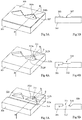
- FIGS. 3A, 3B, 4A, 4B, 5A, 5B , 6A, 6B, 7A, 7B, 8A, 8B , 9A and 9B schematically illustrate steps of a method of manufacturing an embodiment of a screen 400 provided with retroreflective microstructures, compatible with a system of the type described in connection with the figure 1 .
- the Figures 3A, 4A, 5A , 6A, 7A, 8A and 9A are perspective views, and the Figures 3B, 4B, 5B , 6B, 7B, 8B and 9B are sectional views along the BB plane of Figures 3A, 4A, 5A , 6A, 7A, 8A and 9A respectively.
- FIGS. 3A, 3B, 4A, 4B, 5A and 5B illustrate steps of manufacturing a primary mold 320 ( Figures 5A and 5B ) intended to be used during the manufacture of the screen 400 itself.
- the Figures 3A and 3B illustrate a step of arranging a mask 303 on the upper face of a substrate 301 in which it is desired to form the primary mold 320.
- the substrate 301 is for example glass, silicon, a thermoplastic polymer such as poly ( methyl methacrylate) or PMMA, or any other suitable material.
- the upper surface of the substrate 301 is preferably flat.
- the mask 303 comprises through openings 307 revealing portions of the upper surface of the substrate 301 to be etched in a subsequent step.
- the mask 303 is made of a material adapted to protect the unexposed portions of the substrate 301 during the subsequent etching step.
- the mask 303 is made of metal or resin.
- each opening 307 formed in the mask 303 comprises two side walls 308a and 308b substantially orthogonal to each other, joining to form an angle of approximately 90 degrees.
- Each opening 307 has, for example, seen from above, the shape of a convex pentagon.
- each opening 307 has, seen from above, the shape of a right isosceles triangle to which is juxtaposed a trapezium.
- the sides of the right triangle correspond to the side walls 308a and 308b, and the base of the right triangle is confused with a base (the large base in the example shown) of the trapezium.
- the openings 307 are for example all substantially identical and oriented substantially in the same manner.
- openings 307 In the example shown, only two openings 307 have been shown for the sake of simplification. In practice, a large number of openings 307 may be provided. For example, the openings 307 are regularly distributed over the entire upper surface of the substrate 301. The openings 307 are for example arranged in a matrix according to rows and columns.
- each cavity 311 comprises side walls substantially orthogonal to the upper face of the substrate 301 , and a bottom substantially parallel to the upper face of the substrate.
- each cavity comprises two lateral walls 312a and 312b substantially orthogonal to one another, substantially coinciding, seen from above, with the side walls 308a and 308b of the openings 307.
- the side walls 312a and 312b and the bottom 312c of each cavity 311 are join at the same point S, and define a trirectangle trihedron or cube corner having the point S for vertex.
- the axis of symmetry or central axis of the vertex cube corner S forms, by construction, an angle of approximately 54.74 degrees with the upper face of the substrate 301.
- each cavity 311 the vertex cube corner S corresponds to a retroreflective microrefining of the future screen 400.
- the side wall 312d of each cavity 311 opposite the apex S (corresponding to the small base of the trapezium of the opening 307 in the example shown) is preferably relatively far from the vertex S, so as to define in the cavity 311 a clearance region facing the base of the cube corner.
- the cavity 311 has, in the direction of the bisector of the angle formed by the side walls 312a and 312b, a dimension between 1 and 1.5 times the depth of the cavity.
- the cavities 311 have for example a depth in the range of 20 to 500 microns and preferably in the range of 50 to 200 microns.
- the cavities 311 are for example formed by a deep ionic reactive etching process, generally referred to in the art by the acronym DRIE ("Deep Reactive Ion Etching").
- DRIE Deep Reactive Ion Etching
- Such a method has the advantage of making it possible to easily make cavities having substantially vertical lateral faces over relatively high depths, and a substantially horizontal bottom.
- Any other suitable etching process may however be used, for example a laser etching or an X-ray etching.
- the mask 303 (not shown on the Figures 4A and 4B ) is removed.
- the Figures 5A and 5B illustrate a step of forming trenches or recesses 314 with oblique or curved sides in the substrate 301, from the upper face of the substrate.
- the trenches 314 have a depth less than the thickness of the substrate 301.
- the trenches 314 pass through the clearance regions of the cavities 311, avoiding the cube-corner regions corresponding to the retroreflective microrefinements of the screen 400.
- the same trench 314 passes through several cavities 311.
- each trench 314 passes right through the substrate 301 in a direction of alignment of the cavities 311 not passing through the cube-corner portions of the cavities 311
- a localized trench 314 is formed at each cavity 311, i.e. each trench 314 passes through a single cavity 311.
- the trenches 314 have a depth greater than or equal to that of the cavities 311, for example a depth of between 1 and 1.5 times the depth of the cavities 311.
- the trenches 314 preferably have a longitudinal plane of symmetry. substantially orthogonal to the upper surface of the substrate.
- the depth of the trenches 314, their width, and the inclination of their flanks, are chosen so as to eliminate all or part of the vertical walls of the cavities 311 which do not correspond to the cube-corner retroreflective regions of the screen 400.
- the trenches 314 are V trenches.
- V-trenches can for example be obtained by machining the substrate by means of a saw, or by etching.
- V trenches have for example an angular aperture of between 20 and 60 degrees, and preferably of the order of 50 degrees.
- the trenches 314 are trenches with curved flanks, for example trenches C.
- Such trenches may for example be made by etching.
- the trench prediction 314 facilitates a subsequent demolding step of a screen element 400 made from the mold 320.
- the trenches 314 are optional, and may in particular be omitted if it does not arise. no particular difficulty of demolding in this subsequent step.
- the angle of inclination of the flanks of the trenches 314 need not be precisely controlled, since the trenches 314 only serve to facilitate demolding of the screen, but have no optical function. in the final screen.
- the structure obtained after the steps 3A, 3B, 4A, 4B, 5A, 5B corresponds to the primary mold 320.
- the Figures 6A and 6B illustrate a step in which the structures of the upper surface of the primary mold 320 are replicated, by molding, on one face (the upper face in the example shown) of a film 351.
- the film 351 is made of a plastic material, for example of the polymethyl methacrylate type.
- the film 351 is made of a transparent material.
- the replication of the patterns of the primary mold 320 on one side of the film 351 passes through the formation, from the primary mold 320, of a secondary mold (not shown) having a shape complementary to that of the primary mold 320.
- the top of the film 351 are then obtained, from the secondary mold, by thermoforming or by any other suitable molding technique.
- references 311, 312a, 312b, 312c, 312d, S and 314 used to designate elements of the structures of the upper face of the primary mold 320 will be used to designate the corresponding elements.
- the unstructured face of the film 351, namely its underside in the example shown, is preferably substantially flat.
- the Figures 7A and 7B illustrate a step of arranging a mask 353 on the upper face of the film 351.
- the mask 353 comprises through openings 355 revealing portions of the upper face of the film 351. More particularly, the openings 355 are arranged substantially opposite the vertex cube corners S corresponding to the retroreflective microrefinements of the screen 400.
- the remainder of the upper surface of the film 351, and in particular the flat portions of the upper surface of the film 351 not occupied by the cavities 311 and the trenches 314, and the portions of the upper surface of the film 351 corresponding to the trenches 314 and cavity clearance regions 311 are covered by the mask 353.
- the Figures 8A and 8B illustrate the result of a deposition step, through the apertures 355 of the mask 353, of reflective metallizations 357 coating the side walls and the bottom of the cube-corner micro-cavities of the upper face of the film 351.
- the metallizations 357 are for example in aluminium.
- the metallizations 357 may be spray deposited through the openings of the mask.
- the metallizations 357 may overflow on the upper face of the film 351 slightly beyond the limit of the cube corners S vertex.
- each metallization 357 may have the shape of a substantially circular lozenge in which the corresponding right triangle from above, at the cube corner recess coated by the metallization 357.
- the mask 353 is removed.
- the Figures 9A and 9B illustrate a step of bonding a transparent coating film 359 to the upper face of the film 351.
- the faces of the film 359 are substantially planar.
- the coating film 359 and the transparent adhesive 361 have substantially the same refractive index as the film 351.
- the coating film 359 and the transparent adhesive layer 361 ensure a good transparency of the screen 400 outside the areas coated by the metallizations 357. assembly thus obtained forms the screen 400.
- the screen 400 has retroreflective portions regularly distributed over its entire surface, corresponding to the metallized cube corner structures of the film 351. Each portion of the retroreflective screen is surrounded by a portion of transparent screen, so that the screen is partially retroreflective and partially transparent.
- the screen 400 is thus adapted to an operation of the type described in connection with the figure 1 (the upper face of the screen being turned towards the projector 105).
- the coverage rate of the screen 400 by the retroreflective portions is for example less than 50%, and preferably less than 20%.
- the incident rays are deflected by an angle which depends on the optical index of the film 359.
- the maximum efficiency in retroreflection of the cube corner the screen 400 is in principle obtained when the rays projected on these structures are parallel to the central axis of the corners of vertex cube S, i.e. when the rays propagating inside the screen are inclined about 54.74 degrees to the mean plane of the screen.
- Such an inclination of the rays inside the screen can not generally be obtained in practice, this inclination being greater than the limit angle of refraction of the upper diopter of the screen.
- the refractive limit angle is about 42 degrees.
- the angle of incidence of the light rays for which the efficiency in retroreflection of the screen is maximum have shown that, when the films 359 and 351 and the adhesive layer 361 have a refractive index of the order of 1.5, the maximum efficiency in retroreflection of the screen 400 is obtained for an angle of incidence (outside the screen) of the order of 60 degrees.
- the tests carried out show that the proposed structure provides good retroreflection efficiency for angles of incidence in the range of 30 to 80 degrees, and preferably in the range of 50 to 70 degrees.
- the screen 400 is well suited to the application to the projection of an image on a vehicle windshield.
- the screen 400 is relatively simple to implement, because the cube-corner microbreaks forming the retroreflective portions of the screen do not have oblique faces relative to the mean plane of the screen. 'screen.
- the faces of the cube-corner microbreaks of the screen 400 are substantially orthogonal or parallel to the mean plane of the screen.
- the cube corner micro-cavities can be obtained by means of a simple etching vertical sides from the upper surface of the substrate 301.
- the cube corner microrangements forming the retroreflective portions of the screen 400 are not necessarily aligned in rows and columns, but may have a random or semi-random arrangement on the surface of the screen, in particular to avoid possible diffractive phenomena that may occur at certain angles of incidence when the microbreaks have a regular disposition.
- the embodiments described are not limited to the exemplary method of producing the reflective metallizations 357 described in connection with the FIGS. 7A, 7B, 8A, 8B .
- the step of producing the mask 353 described in connection with the Figures 7A and 7B can be omitted. Instead, a conformal metal layer covering the entire upper surface of the structure of the Figures 6A and 6B can be realized. The deposited metal can then be removed at the level of the upper planar regions of the structure (corresponding to the transparent areas of the screen), for example by mechanical-chemical polishing. During this step, only the portions of the metal layer coating the walls of the cavities 311, and, where appropriate, the trenches 314, are preserved, forming the reflective metallizations 357.
- the light source 105 is usually not placed exactly in the axis of the user's gaze.
- the screen 400 should preferably be adapted to diffuse the retroreflected light in a diffusion cone encompassing the pupils of the user, so that the user can see the image displayed by the projector.
- the inventors have found that the diffraction effects on the edges of microrenfoncements and / or the inevitable surface imperfections of the screen, may be sufficient to obtain the required diffusion effect.
- the described embodiments are not limited to the application to the projection of an image on a transparent surface.
- the embodiments described may have applications in various fields using retroreflective surfaces, not necessarily transparent, for example for signaling purposes.
- such a surface may have utility for ground signaling applications in the field of motor vehicle routes.
- the transparency is not sought, it will preferably seek to maximize the coverage rate of the screen by the retroreflective portions of cube corners.
- the material of the film 351 may be non-transparent.
- the coating film 359 and the intermediate adhesive layer 361 must be transparent to allow the incident light to reach the cube-corner metallizations 357 and then to emerge from the screen after reflection on the faces of the metallizations. Alternatively, the coating film 359 and the intermediate glue layer 361 may be omitted. On the other hand, if the transparency of the screen is not required, the reflective metallizations 357 are not necessarily located on the cube corner portions of the substrate 351, but can form a continuous layer made by conformal deposition, coating the entire upper surface of the substrate 351.
- film has been used to designate the elements 351 and 359 of the screen 400. This term must, however, be broadly understood, and notably includes elements similar to films such as leaves, plates, etc.
- structures of shapes complementary to those of the primary mold 320 may be formed on the upper face of the film 351.
- the upper face of the transparent film 351 can be molded directly from the primary mold 320. In this case, one obtains microprotuberances in cube corners on the side of the upper face of the film 351.
- the film 351 then forms a retroreflective screen intended, as in the example of the figure 2 to be illuminated by its underside.
- Reflections on the side faces of cube corners can be based on the principle of total internal reflection.
- the side faces of the cube corners may be covered with a reflective material on the side of the upper face of the screen, the reflections on the side faces of the cube corners then being reflections of the mirror type.
- a retroreflective screen comprising a first film made of a transparent material, one face of which comprises a plurality of microprotuberances, each microprotuberance having a first face substantially parallel to the mean plane of the screen, and second and third faces. substantially orthogonal to each other and substantially orthogonal to the first face, the first, second and third faces of the microprotuberance joining at one point and forming a trihedron.
- the first, second and third faces of each microprotuberance may be coated by a reflective metallization.
- Said face of the first film may further comprise oblique or curved side strips, each microprotrusion being contiguous to one of the strips.
- microprotuberances are contiguous to the same band.
- the rate of recovery of the screen by the microprotuberances is for example less than 50%.
- the screen may include microprotrusions of different sizes and / or orientations in different areas of the screen.
- microprotuberances (311) are for example distributed in a random or semi-random arrangement on the surface of the screen.
Landscapes
- Physics & Mathematics (AREA)
- General Physics & Mathematics (AREA)
- Optics & Photonics (AREA)
- Engineering & Computer Science (AREA)
- Mechanical Engineering (AREA)
- Manufacturing & Machinery (AREA)
- Health & Medical Sciences (AREA)
- Ophthalmology & Optometry (AREA)
- Optical Elements Other Than Lenses (AREA)
- Overhead Projectors And Projection Screens (AREA)
Abstract
Description
- La présente demande concerne le domaine des systèmes d'affichage d'images sur des surfaces transparentes telles que des parebrises de véhicules, notamment de véhicules automobiles. Elle vise plus particulièrement un écran muni de microstructures réfléchissantes adapté à un tel système, un procédé de réalisation d'un tel écran, et un moule pour la réalisation d'un tel écran.
- La demanderesse a récemment proposé, dans la demande de brevet français N°
FR14/53404 PCT/FR2015/050956 - La
figure 1 est une vue en coupe schématique d'un tel système. Ce système comprend un écran 103 revêtant la face intérieure d'un parebrise 101, c'est-à-dire sa face tournée vers l'intérieur du véhicule, et un projecteur 105 adapté à être monté sur la tête d'un utilisateur 107, par exemple le conducteur du véhicule. Le projecteur 105 est adapté à projeter une image sur tout ou partie de la surface de l'écran 103 tournée vers l'intérieur du véhicule (c'est-à-dire opposée au pare-brise 101). L'écran 103 est partiellement transparent et partiellement rétroréfléchissant. Plus particulièrement, l'écran 103 est adapté à rétroréfléchir - c'est-à-dire réfléchir en direction de sa source - de la lumière projetée sur sa face tournée vers l'intérieur du véhicule, et à laisser passer sans altération significative de la lumière provenant du pare-brise 101, c'est-à-dire de l'extérieur du véhicule. L'écran 103 a ainsi une fonction de transparence, permettant à l'utilisateur de voir la scène extérieure à travers le pare-brise 101 depuis l'intérieur du véhicule, et une fonction de rétroréflexion, permettant à l'utilisateur - dont les pupilles sont voisines du projecteur 105 - de voir, en superposition de la scène extérieure, une image produite par le projecteur 105. - La
figure 2 est une vue en coupe représentant plus en détail l'écran 103 du système de lafigure 1 . - L'écran 103 est constitué d'un film en un matériau transparent dont une face 201a est approximativement lisse et dont une face 201b opposée à la face 201a présente des protubérances 203 sensiblement identiques régulièrement réparties sur la surface du film. Chaque protubérance 203 a sensiblement la forme d'un coin de cube, c'est-à-dire d'un trièdre comportant trois faces latérales triangulaires mutuellement perpendiculaires se rejoignant en un même point ou sommet, et, à l'opposé du sommet, une base, par exemple en forme de triangle équilatéral. Chaque protubérance 203 a son sommet pointant vers l'extérieur du film. Les bases des protubérances 203 sont parallèles à la face lisse 201a de l'écran, et l'axe central de chaque protubérance 203 (c'est-à-dire l'axe passant par le sommet du trièdre et par le centre de sa base) est orthogonal au plan moyen du film. Ainsi, les trois faces du trièdre sont obliques par rapport au plan moyen du film.
- L'écran 103 se distingue d'un écran rétroréfléchissant à coins de cube traditionnel, en ce que, dans l'écran 103, les protubérances 203 ne sont pas adjacentes mais sont séparées les unes des autres par des zones sensiblement lisses 205 de la face 201b, parallèles ou approximativement parallèles à la face 201a de l'écran.
- L'écran 103 est destiné à être éclairé par le projecteur 105 (
figure 1 ) par sa face 201a, comme l'illustre schématiquement la flèche 207 de lafigure 2 . Les portions d'écran situées en regard des zones lisses 205 de la face 201a correspondent à des portions transparentes de l'écran 103, laissant passer la lumière dans les deux sens sans déformation significative. Les portions d'écran situées en regard des protubérances 203 correspondent quant à elles à des portions rétroréfléchissantes non transparentes de l'écran 103, adaptées à renvoyer en direction de sa source la lumière provenant du projecteur 105. Plus particulièrement, lorsqu'un faisceau lumineux incident (non représenté) atteint une portion rétroréfléchissante de l'écran 103, ce faisceau traverse une partie de l'épaisseur de l'écran jusqu'à atteindre la base du coin de cube 203 correspondant, pénètre dans le coin de cube, est réfléchi sur chacune des trois faces latérales du coin de cube, et, après réflexion sur la troisième face latérale, repart en direction de sa source. Dans l'exemple représenté, les réflexions sur les faces latérales des coins de cube sont basées sur le principe de la réflexion totale interne. A titre de variante, les faces latérales des coins de cube peuvent être recouvertes d'un matériau réfléchissant du côté de la face 201b de l'écran. Les réflexions sur les faces latérales des coins de cube sont alors des réflexions de type miroir. - Un mode de réalisation prévoit un écran rétroréfléchissant comportant un premier film en un matériau transparent dont une face comprend une pluralité de microprotubérances, chaque microprotubérance ayant une première face sensiblement parallèle au plan moyen de l'écran, et des deuxième et troisième faces sensiblement orthogonales entre elles et sensiblement orthogonales à la première face, les première, deuxième et troisième faces de la microprotubérance se rejoignant en un même point et formant un trièdre.
- Selon un mode de réalisation, les première, deuxième et troisième faces de chaque microprotubérance du premier film sont revêtues par une métallisation réfléchissante.
- Selon un mode de réalisation, la face du premier film comprend en outre des bandes à flancs obliques ou incurvés, chaque microprotubérance étant accolée à l'une des bandes.
- Selon un mode de réalisation, plusieurs microprotubérances du premier film sont accolées à une même bande.
- Selon un mode de réalisation, le taux de recouvrement de l'écran par les microprotubérances du premier film est inférieur à 50 %.
- Selon un mode de réalisation, la face du premier film comprend des microprotubérances de dimensions et/ou d'orientations différentes dans des zones différentes de l'écran.
- Selon un mode de réalisation, les microprotubérances du premier film sont réparties selon une disposition aléatoire ou semi-aléatoire sur la surface de l'écran.
- Un autre mode de réalisation prévoit un procédé de fabrication d'un écran rétroréfléchissant du type susmentionné, comprenant la fabrication d'un moule dont une face présente des structurations de formes complémentaires à celles des structurations de la face du premier film de l'écran.
- Selon un mode de réalisation, la fabrication du moule comprend une étape de gravure de microrenfoncements du côté d'une première face d'un substrat, chaque microrenfoncement ayant un fond sensiblement parallèle au plan moyen de l'écran et des première et deuxième parois latérales sensiblement orthogonales entre elles et sensiblement orthogonales au fond, les première et deuxième parois latérales et le fond du microrenfoncement se rejoignant en un même point et formant un trièdre.
- Selon un mode de réalisation, la fabrication du moule comprend en outre une étape de formation, du côté de la face du substrat, de tranchées à flancs obliques ou courbes, chaque microrenfoncement débouchant dans une tranchée.
- Selon un mode de réalisation, le procédé comporte en outre une étape de réalisation, sur ladite face du premier film, de motifs complémentaires à ceux de ladite face du moule, par moulage à partir du moule.
- Ces caractéristiques et leurs avantages, ainsi que d'autres, seront exposés en détail dans la description suivante de modes de réalisation particuliers faite à titre non limitatif en relation avec les figures jointes parmi lesquelles :
- la
figure 1 , précédemment décrite, est une vue en coupe représentant de façon schématique un exemple d'un système d'affichage d'une image sur un parebrise ; - la
figure 2 , précédemment décrite, est une vue en coupe représentant plus en détail un écran du système de lafigure 1 ; - les
figures 3A, 4A, 5A ,6A, 7A, 8A et9A sont des vues en perspective illustrant schématiquement des étapes successives d'un exemple de procédé de fabrication d'un mode de réalisation d'un écran muni de microstructures rétroréfléchissantes ; et - les
figures 3B, 4B, 5B ,6B, 7B, 8B et9B sont des vues en coupe des structures desfigures 3A, 4A, 5A ,6A, 7A, 8A et9A respectivement. - De mêmes éléments ont été désignés par de mêmes références aux différentes figures et, de plus, les diverses figures ne sont pas tracées à l'échelle. Dans la description qui suit, lorsque l'on fait référence à des qualificatifs de position absolue, tels que les termes "avant", "arrière", "haut", "bas", "gauche", "droite", etc., ou relative, tels que les termes "dessus", "dessous", "supérieur", "inférieur", etc., ou à des qualificatifs d'orientation, tels que les termes "horizontal", "vertical", etc., il est fait référence à l'orientation des vues en coupe correspondantes, étant entendu que, dans la pratique, les dispositifs décrits peuvent être orientés différemment. Sauf précision contraire, les expressions "approximativement", "environ", "sensiblement", et "de l'ordre de" signifient à 10 % près, de préférence à 1 % près, ou, lorsqu'il s'agit de valeurs angulaires ou assimilées (par exemple les qualificatifs d'orientation tels que les termes parallèle, orthogonal, vertical, horizontal, etc.) à 1 degré près, de préférence à 0,1° près.
- Une limitation de l'écran 103 de la
figure 2 est que son efficacité en rétroréflexion, très bonne pour des angles d'incidence du faisceau projeté voisins de la normale à l'écran, par exemple pour des angles d'incidence compris entre 0 et 20 degrés, chute fortement lorsque l'angle d'incidence du faisceau projeté augmente. A titre d'illustration, des mesures de l'intensité du faisceau rétroréfléchi ont été réalisées sur un écran du type décrit en relation avec lafigure 2 pour différents angles du faisceau incident. Ces mesures montrent que l'intensité du faisceau rétroréfléchi est maximale pour un angle d'incidence nul (incidence normale), chute à environ 50 % de sa valeur maximale pour un angle d'incidence de 25°, et descend à 10 % de sa valeur maximale pour un angle d'incidence de 50°. - Ceci peut poser problème pour l'application à la projection d'une image sur un parebrise de véhicule. En effet, dans de nombreux véhicules, le parebrise est fortement incliné par rapport à la verticale. De plus, dans un système du type décrit en relation avec la
figure 1 , le projecteur 105 monté sur la tête de l'utilisateur peut avoir son axe principal de projection incliné vers le bas par rapport à l'horizontale. Ainsi, l'angle formé entre l'axe principal du projecteur 105 et l'écran 103 revêtant le parebrise peut atteindre des valeurs élevées, par exemple de l'ordre de 50 à 70 degrés. A de tels angles d'incidence, l'efficacité en rétroréflexion de l'écran 103 de lafigure 2 est relativement faible. - Une autre limitation de l'écran 103 de la
figure 2 réside dans sa grande complexité de fabrication, liée notamment au fait que les protubérances rétroréfléchissantes 203 présentent des faces obliques (par rapport au plan moyen de l'écran) dont les angles d'inclinaison doivent être contrôlés de façon très précise pour obtenir l'effet rétroréfléchissant recherché. - Les
figures 3A, 3B, 4A, 4B, 5A, 5B ,6A, 6B, 7A, 7B, 8A, 8B ,9A et 9B illustrent schématiquement des étapes d'un procédé de fabrication d'un mode de réalisation d'un écran 400 muni de microstructures rétroréfléchissantes, compatible avec un système du type décrit en relation avec lafigure 1 . Lesfigures 3A, 4A, 5A ,6A, 7A, 8A et9A sont des vues en perspective, et lesfigures 3B, 4B, 5B ,6B, 7B, 8B et9B sont des vues en coupe selon le plan B-B desfigures 3A, 4A, 5A ,6A, 7A, 8A et9A respectivement. - Les
figures 3A, 3B, 4A, 4B, 5A et 5B illustrent des étapes de fabrication d'un moule primaire 320 (figures 5A et 5B ) destiné à être utilisé lors de la fabrication de l'écran 400 proprement dit. - Les
figures 3A et 3B illustrent une étape de disposition d'un masque 303 sur la face supérieure d'un substrat 301 dans lequel on souhaite former le moule primaire 320. Le substrat 301 est par exemple en verre, en silicium, en un polymère thermoplastique tel que le poly(méthacrylate de méthyle) ou PMMA, ou en tout autre matériau adapté. La surface supérieure du substrat 301 est de préférence plane. Le masque 303 comprend des ouvertures traversantes 307 laissant apparaître des portions de la surface supérieure du substrat 301 destinées à être gravées lors d'une étape ultérieure. Le masque 303 est en un matériau adapté à protéger les portions non exposées du substrat 301 lors de l'étape ultérieure de gravure. A titre d'exemple, le masque 303 est en métal ou en résine. Vu de dessus, chaque ouverture 307 formée dans le masque 303 comprend deux parois latérales 308a et 308b sensiblement orthogonales entre elles, se rejoignant pour former un angle d'approximativement 90 degrés. Chaque ouverture 307 a par exemple, vu de dessus, la forme d'un pentagone convexe. Dans l'exemple représenté, chaque ouverture 307 a, vu de dessus, la forme d'un triangle isocèle rectangle auquel est juxtaposé un trapèze. Les côtés du triangle rectangle correspondent aux parois latérales 308a et 308b, et la base du triangle rectangle est confondue avec une base (la grande base dans l'exemple représenté) du trapèze. Les ouvertures 307 sont par exemple toutes sensiblement identiques et orientées sensiblement de la même manière. Dans l'exemple représenté, seules deux ouvertures 307 ont été représentées par souci de simplification. En pratique, un grand nombre d'ouvertures 307 peut être prévu. A titre d'exemple, les ouvertures 307 sont régulièrement réparties sur toute la surface supérieure du substrat 301. Les ouvertures 307 sont par exemple disposées en matrice selon des rangées et des colonnes. - Les
figures 4A et 4B illustrent une étape de formation de cavités ou renfoncements 311 s'étendant sensiblement verticalement dans le substrat 301, depuis sa face supérieure, en regard des ouvertures 307 du masque 303. Chaque cavité 311 comprend des parois latérales sensiblement orthogonales à la face supérieure du substrat 301, et un fond sensiblement parallèle à la face supérieure du substrat. En particulier, chaque cavité comprend deux parois latérales 312a et 312b sensiblement orthogonales entre elles, coïncidant sensiblement, vu de dessus, avec les parois latérales 308a et 308b des ouvertures 307. Les parois latérales 312a et 312b et le fond 312c de chaque cavité 311 se rejoignent en un même point S, et définissent un trièdre trirectangle ou coin de cube ayant le point S pour sommet. Dans chaque cavité 311, l'axe de symétrie ou axe central du coin de cube de sommet S forme, par construction, un angle d'approximativement 54,74 degrés avec la face supérieure du substrat 301. - Comme cela sera expliqué plus en détail ci-après, dans chaque cavité 311, le coin de cube de sommet S correspond à un microrenfoncement rétroréfléchissant du futur écran 400. La paroi latérale 312d de chaque cavité 311 opposée au sommet S (correspondant à la petite base du trapèze de l'ouverture 307 dans l'exemple représenté) est de préférence relativement éloignée du sommet S, de façon à définir dans la cavité 311 une région de dégagement en regard de la base du coin de cube. A titre d'exemple, vu de dessus, la cavité 311 présente, dans la direction de la bissectrice de l'angle formé par les parois latérales 312a et 312b, une dimension comprise entre 1 et 1,5 fois la profondeur de la cavité. Les cavités 311 ont par exemple une profondeur comprise dans la plage allant de 20 à 500 µm et de préférence comprise dans la plage allant de 50 à 200 µm.
- Les cavités 311 sont par exemple formées par un procédé de gravure réactive ionique profonde, généralement désigné dans la technique par l'acronyme anglo-saxon DRIE ("Deep Reactive Ion Etching"). Un tel procédé présente l'avantage de permettre de réaliser aisément des cavités ayant des faces latérales sensiblement verticales sur des profondeurs relativement élevées, et un fond sensiblement horizontal. Tout autre procédé de gravure adapté pourra cependant être utilisé, par exemple une gravure par laser ou une gravure par rayons X.
- Une fois la gravure réalisée, le masque 303 (non représenté sur les
figures 4A et 4B ) est retiré. - Les
figures 5A et 5B illustrent une étape de formation de tranchées ou évidements 314 à flancs obliques ou incurvés dans le substrat 301, depuis la face supérieure du substrat. Les tranchées 314 ont une profondeur inférieure à l'épaisseur du substrat 301. Les tranchées 314 traversent les régions de dégagement des cavités 311, en évitant les régions en coins de cube correspondant aux microrenfoncements rétroréfléchissants de l'écran 400. De préférence, une même tranchée 314 traverse plusieurs cavités 311. A titre d'exemple, vu de dessus, chaque tranchée 314 traverse de part en part le substrat 301 dans une direction d'alignement des cavités 311 ne passant pas par les portions en coins de cube des cavités 311. A titre de variante, une tranchée 314 localisée est formée au niveau de chaque cavité 311, c'est-à-dire que chaque tranchée 314 traverse une unique cavité 311. - Les tranchées 314 ont une profondeur supérieure ou égale à celle des cavités 311, par exemple une profondeur comprise entre 1 et 1,5 fois la profondeur des cavités 311. Les tranchées 314 présentent de préférence un plan de symétrie longitudinal sensiblement orthogonal à la surface supérieure du substrat. La profondeur des tranchées 314, leur largeur, et l'inclinaison de leurs flancs, sont choisies de façon à éliminer tout ou partie des parois verticales des cavités 311 qui ne correspondent pas aux régions rétroréfléchissantes en coins de cube de l'écran 400.
- A titre d'exemple, les tranchées 314 sont des tranchées en V. Des tranchées en V peuvent par exemple être obtenues par usinage du substrat au moyen d'une scie, ou par gravure. Les tranchées en V ont par exemple une ouverture angulaire comprise entre 20 et 60 degrés, et de préférence de l'ordre de 50 degrés.
- A titre de variante, les tranchées 314 sont des tranchées à flancs incurvés, par exemple des tranchées en C. De telles tranchées peuvent par exemple être réalisées par gravure.
- La prévision des tranchées 314 permet de faciliter une étape ultérieure de démoulage d'un élément de l'écran 400 réalisé à partir du moule 320. On notera toutefois que les tranchées 314 sont optionnelles, et peuvent notamment être omises s'il ne se pose pas de difficulté particulière de démoulage lors de cette étape ultérieure. On notera en outre que l'angle d'inclinaison des flancs des tranchées 314 n'a pas besoin d'être précisément contrôlé, car les tranchées 314 servent uniquement à faciliter le démoulage de l'écran, mais n'ont pas de fonction optique dans l'écran final. La structure obtenue à l'issue des étapes 3A, 3B, 4A, 4B, 5A, 5B correspond au moule primaire 320.
- Les
figures 6A et 6B illustrent une étape au cours de laquelle les structurations de la surface supérieure du moule primaire 320 sont répliquées, par moulage, sur une face (la face supérieure dans l'exemple représenté) d'un film 351. A titre d'exemple, le film 351 est en un matériau plastique, par exemple de type polyméthacrylate de méthyle. Dans cet exemple, le film 351 est en un matériau transparent. La réplication des motifs du moule primaire 320 sur une face du film 351, passe par la formation, à partir du moule primaire 320, d'un moule secondaire (non représenté) ayant une forme complémentaire de celle du moule primaire 320. Les structurations de la face supérieure du film 351 sont alors obtenues, à partir du moule secondaire, par thermoformage ou par toute autre technique de moulage adaptée. Par souci de simplification, dans la suite de la description, les références 311, 312a, 312b, 312c, 312d, S et 314 utilisées pour désigner des éléments des structurations de la face supérieure du moule primaire 320, seront utilisées pour désigner les éléments correspondants des structurations de la face supérieure du film 351. La face non structurée du film 351, à savoir sa face inférieure dans l'exemple représenté, est de préférence sensiblement plane. - Les
figures 7A et 7B illustrent une étape de disposition d'un masque 353 sur la face supérieure du film 351. Le masque 353 comprend des ouvertures traversantes 355 laissant apparaître des portions de la face supérieure du film 351. Plus particulièrement, les ouvertures 355 sont disposées sensiblement en regard des coins de cube de sommet S correspondant aux microrenfoncements rétroréfléchissants de l'écran 400. Le reste de la surface supérieure du film 351, et notamment les portions planes de la surface supérieure du film 351 non occupées par les cavités 311 et les tranchées 314, ainsi que les portions de la surface supérieure du film 351 correspondant aux tranchées 314 et aux régions de dégagement des cavités 311, sont recouvertes par le masque 353. - Les
figures 8A et 8B illustrent le résultat d'une étape de dépôt, au travers des ouvertures 355 du masque 353, de métallisations réfléchissantes 357 revêtant les parois latérales et le fond des microrenfoncements en coins de cube de la face supérieure du film 351. Les métallisations 357 sont par exemple en aluminium. Les métallisations 357 peuvent être déposées par pulvérisation au travers des ouvertures du masque. En pratique, les métallisations 357 peuvent déborder sur la face supérieure du film 351 légèrement au-delà de la limite des coins de cube de sommet S. A titre d'exemple, vu de dessus, chaque métallisation 357 peut avoir la forme d'une pastille sensiblement circulaire dans laquelle s'inscrit le triangle rectangle correspondant, vu de dessus, au renfoncement en coin de cube revêtu par la métallisation 357. - Une fois les métallisations 357 déposées, le masque 353 est retiré.
- Les
figures 9A et 9B illustrent une étape de collage d'un film de revêtement transparent 359 sur la face supérieure du film 351. Dans cet exemple, les faces du film 359 sont sensiblement planes. Une couche de colle transparente 361 comblant notamment les cavités 311 et les tranchées 314 de la face supérieure du film 351, fait interface entre la face supérieure du film 351 et la face inférieure du film 359. De préférence, le film de revêtement 359 et la colle transparente 361 ont sensiblement le même indice de réfraction que le film 351. Le film de revêtement 359 et la couche de colle transparente 361 permettent de garantir une bonne transparence de l'écran 400 en dehors des zones revêtues par les métallisations 357. L'assemblage ainsi obtenu forme l'écran 400. - L'écran 400 présente des portions rétroréfléchissantes régulièrement réparties sur toute sa surface, correspondant aux structurations en coins de cube métallisées du film 351. Chaque portion d'écran rétroréfléchissante est entourée par une portion d'écran transparente, de sorte que l'écran est partiellement rétroréfléchissant et partiellement transparent. L'écran 400 est ainsi adapté à un fonctionnement du type décrit en relation avec la
figure 1 (la face supérieure de l'écran étant tournée vers le projecteur 105). Pour obtenir une bonne transparence de l'écran 400 permettant la visualisation d'une scène extérieure, le taux de recouvrement de l'écran 400 par les portions rétroréfléchissantes est par exemple inférieur à 50 %, et de préférence inférieur à 20 %. - Lorsqu'ils pénètrent dans l'écran 400 par la face supérieure du film 359, les rayons incidents sont déviés d'un angle qui dépend de l'indice optique du film 359. L'efficacité maximale en rétroréflexion des structurations en coin de cube de l'écran 400 est en principe obtenue lorsque les rayons projetés sur ces structurations sont parallèles à l'axe central des coins de cube de sommet S, c'est-à-dire lorsque les rayons se propageant à l'intérieur de l'écran sont inclinés d'environ 54,74 degrés par rapport au plan moyen de l'écran. Une telle inclinaison des rayons à l'intérieur de l'écran ne peut généralement pas être obtenue dans la pratique, cette inclinaison étant supérieure à l'angle limite de réfraction du dioptre supérieur de l'écran. A titre d'exemple, pour un film 359 d'indice optique de l'ordre de 1,5, l'angle limite de réfraction est d'environ 42 degrés. On notera en outre que plus l'angle d'incidence des rayons lumineux sur l'écran 400 est élevé, plus les pertes par réflexion sur la face supérieure de l'écran 400 sont importantes. En fonction des matériaux choisis, on pourra aisément trouver, par mesure et/ou simulation, l'angle d'incidence des rayons lumineux pour lequel l'efficacité en rétroréflexion de l'écran est maximale. A titre d'exemple, des mesures ont montré que, lorsque les films 359 et 351 et la couche de colle 361 ont un indice de réfraction de l'ordre de 1,5, l'efficacité maximale en rétroréflexion de l'écran 400 est obtenue pour un angle d'incidence (à l'extérieur de l'écran) de l'ordre de 60 degrés. Plus généralement, les essais réalisés montrent que la structure proposée procure une bonne efficacité en rétroréflexion pour des angles d'incidence compris dans la plage allant de 30 à 80 degrés, et de préférence dans la plage allant de 50 à 70 degrés. Ainsi, l'écran 400 est bien adapté à l'application à la projection d'une image sur un pare-brise de véhicule.
- Un autre avantage de l'écran 400 est qu'il est relativement simple à réaliser, en raison du fait que les microrenfoncements en coins de cube formant les portions rétroréfléchissantes de l'écran ne comportent pas de faces obliques par rapport au plan moyen de l'écran. Les faces des microrenfoncements en coins de cube de l'écran 400 sont sensiblement orthogonales ou parallèles au plan moyen de l'écran. Ainsi, les microrenfoncements en coins de cube peuvent être obtenus au moyen d'une simple gravure à flancs verticaux depuis la surface supérieure du substrat 301.
- Des modes de réalisation particuliers ont été décrits. Diverses variantes et modifications apparaîtront à l'homme de l'art. En particulier, les modes de réalisation décrits ne se limitent pas à l'exemple susmentionné dans lequel les microrenfoncements en coins de cube formant les portions rétroréfléchissantes de l'écran 400 sont sensiblement identiques et orientés de la même manière. En pratique, selon les besoins de l'application, des microrenfoncements en coins de cube peuvent avoir des dimensions différentes et/ou des orientations différentes (en vue de dessus) dans des zones différentes de l'écran.
- En outre, les microrenfoncements en coins de cube formant les portions rétroréfléchissantes de l'écran 400 ne sont pas nécessairement alignés en lignes et en colonnes, mais peuvent présenter une disposition aléatoire ou semi-aléatoire sur la surface de l'écran, de façon notamment à éviter d'éventuels phénomènes diffractifs susceptibles de se produire sous certains angles d'incidence lorsque les microrenfoncements ont une disposition régulière.
- De plus, les modes de réalisation décrits ne se limitent pas à l'exemple de procédé de réalisation des métallisations réfléchissantes 357 décrit en relation avec les
figures 7A, 7B, 8A, 8B . A titre de variante, l'étape de réalisation du masque 353 décrite en relation avec lesfigures 7A et 7B peut être omise. A la place, une couche métallique conforme revêtant toute la surface supérieure de la structure desfigures 6A et 6B peut être réalisée. Le métal déposé peut ensuite être retiré au niveau des régions planes supérieures de la structure (correspondant aux zones transparentes de l'écran), par exemple par polissage mécano-chimique. Lors de cette étape, seules les portions de la couche métallique revêtant les parois des cavités 311, et, le cas échéant, des tranchées 314, sont conservées, formant les métallisations réfléchissantes 357. - Par ailleurs, on notera que dans une application du type décrit en relation avec la
figure 1 , la source lumineuse 105 n'est généralement pas placée exactement dans l'axe du regard de l'utilisateur. Ainsi, l'écran 400 doit de préférence être adapté à diffuser la lumière rétroréfléchie dans un cône de diffusion englobant les pupilles de l'utilisateur, pour que l'utilisateur puisse voir l'image affichée par le projecteur. En pratique, les inventeurs ont constaté que les effets de diffraction sur les bords des microrenfoncements et/ou les inévitables imperfections de surface de l'écran, peuvent suffire à obtenir l'effet de diffusion requis. Pour amplifier et/ou contrôler cette diffusion, on peut par exemple jouer sur la rugosité des flancs et du fond des cavités 311 du moule primaire 320. - En outre, les modes de réalisation décrits ne se limitent pas à l'application à la projection d'une image sur une surface transparente. En particulier, les modes de réalisation décrits peuvent avoir des applications dans divers domaines utilisant des surfaces rétroréfléchissantes, non nécessairement transparentes, par exemple à des fins de signalisation. Dans certains cas, il peut en effet être souhaitable de pouvoir disposer d'une surface présentant une bonne efficacité en rétroréflexion pour des angles d'incidences élevés. A titre d'exemple, une telle surface peut avoir une utilité pour des applications de signalisation au sol dans le domaine des routes pour véhicules automobiles. Dans le cas où la transparence n'est pas recherchée, on cherchera de préférence à maximiser le taux de recouvrement de l'écran par les portions rétroréfléchissantes en coins de cube. En outre, le matériau du film 351 pourra être non transparent. Le film de revêtement 359 et la couche de colle intermédiaire 361 doivent en revanche être transparents pour permettre à la lumière incidente d'atteindre les métallisations en coins de cube 357 puis de ressortir de l'écran après réflexion sur les faces des métallisations. A titre de variante, le film de revêtement 359 et la couche de colle intermédiaire 361 peuvent être omis. Par ailleurs, si la transparence de l'écran n'est pas requise, les métallisations réfléchissantes 357 ne sont pas nécessairement localisées sur les portions en coin de cube du substrat 351, mais peuvent former une couche continue réalisée par dépôt conforme, revêtant toute la surface supérieure du substrat 351.
- On notera que dans la présente description, le terme film a été employé pour désigner les éléments 351 et 359 de l'écran 400. Ce terme doit toutefois s'entendre de façon large, et inclut notamment des éléments similaires à des films tels que des feuilles, plaques, etc.
- Par ailleurs, à titre de variante, au lieu de répliquer à l'identique les structurations de la surface du moule primaire 320 (
figures 5A, 5B ) sur la face supérieure du film 351 (figures 6A et 6B ), des structurations de formes complémentaires à celles du moule primaire 320 peuvent être formées sur la face supérieure du film 351. Autrement dit, plutôt que de former un moule secondaire à partir du moule primaire 320 puis de mouler la face supérieure du film 351 à partir du moule secondaire, la face supérieure du film transparent 351 peut être moulée directement à partir du moule primaire 320. Dans ce cas, on obtient des microprotubérances en coins de cube du côté de la face supérieure du film 351. Le film 351 forme alors un écran rétroréfléchissant destiné, comme dans l'exemple de lafigure 2 , à être éclairé par sa face inférieure. Lorsqu'un faisceau lumineux incident (non représenté) atteint une portion rétroréfléchissante de l'écran, ce faisceau traverse une partie de l'épaisseur de l'écran jusqu'à atteindre la base de la protubérance en coins de cube correspondante, pénètre dans le coin de cube, est réfléchi sur chacune des trois faces latérales du coin de cube, et, après réflexion sur la troisième face latérale, repart en direction de sa source. Les réflexions sur les faces latérales des coins de cube peuvent être basées sur le principe de la réflexion totale interne. A titre de variante, les faces latérales des coins de cube peuvent être recouvertes d'un matériau réfléchissant du côté de la face supérieure de l'écran, les réflexions sur les faces latérales des coins de cube étant alors des réflexions de type miroir. - Ainsi, dans une variante, on prévoit un écran rétroréfléchissant comportant un premier film en un matériau transparent dont une face comprend une pluralité de microprotubérances, chaque microprotubérance ayant une première face sensiblement parallèle au plan moyen de l'écran, et des deuxième et troisième faces sensiblement orthogonales entre elles et sensiblement orthogonales à la première face, les première, deuxième et troisième faces de la microprotubérance se rejoignant en un même point et formant un trièdre.
- Les première, deuxième et troisième faces de chaque microprotubérance peuvent être revêtues par une métallisation réfléchissante.
- Ladite face du premier film peut en outre comprendre des bandes à flancs obliques ou incurvés, chaque microprotubérance étant accolée à l'une des bandes.
- A titre d'exemple, plusieurs microprotubérances sont accolées à une même bande.
- Le taux de recouvrement de l'écran par les microprotubérances est par exemple inférieur à 50 %.
- L'écran peut comprendre des microprotubérances de dimensions et/ou d'orientations différentes dans des zones différentes de l'écran.
- Les microprotubérances (311) sont par exemple réparties selon une disposition aléatoire ou semi-aléatoire sur la surface de l'écran.
Claims (11)
- Ecran rétroréfléchissant comportant un premier film (351) en un matériau transparent dont une face comprend une pluralité de microprotubérances, chaque microprotubérance ayant une première face sensiblement parallèle au plan moyen de l'écran, et des deuxième et troisième faces sensiblement orthogonales entre elles et sensiblement orthogonales à la première face, les première, deuxième et troisième faces de la microprotubérance se rejoignant en un même point et formant un trièdre.
- Ecran selon la revendication 1, dans lequel, les première, deuxième et troisième faces de chaque microprotubérance du premier film (351) sont revêtues par une métallisation réfléchissante.
- Ecran selon la revendication 1 ou 2, dans lequel ladite face du premier film (351) comprend en outre des bandes à flancs obliques ou incurvés, chaque microprotubérance étant accolée à l'une des bandes.
- Ecran selon la revendication 3, dans lequel plusieurs microprotubérances du premier film (351) sont accolées à une même bande.
- Ecran selon l'une quelconque des revendications 1 à 4, dans lequel le taux de recouvrement de l'écran par les microprotubérances du premier film (351) est inférieur à 50 %.
- Ecran selon l'une quelconque des revendications 1 à 5, dans lequel ladite face du premier film (351) comprend des microprotubérances de dimensions et/ou d'orientations différentes dans des zones différentes de l'écran.
- Ecran selon l'une quelconque des revendications 1 à 6, dans lequel les microprotubérances du premier film (351) sont réparties selon une disposition aléatoire ou semi-aléatoire sur la surface de l'écran.
- Procédé de fabrication d'un écran rétroréfléchissant selon l'une quelconque des revendications 1 à 7, comprenant la fabrication d'un moule (320) dont une face présente des structurations de formes complémentaires à celles des structurations de ladite face du premier film (351) de l'écran (400).
- Procédé selon la revendication 8, dans lequel la fabrication du moule (320) comprend une étape de gravure de microrenfoncements (311) du côté d'une première face d'un substrat (301), chaque microrenfoncement (311) ayant un fond (312c) sensiblement parallèle au plan moyen de l'écran (400) et des première (312a) et deuxième (312b) parois latérales sensiblement orthogonales entre elles et sensiblement orthogonales au fond (312c), les première (312a) et deuxième (312b) parois latérales et le fond (312c) du microrenfoncement (311) se rejoignant en un même point (S) et formant un trièdre.
- Procédé selon la revendication 9, dans lequel la fabrication du moule (320) comprend en outre une étape de formation, du côté de ladite face du substrat (301), de tranchées (314) à flancs obliques ou courbes, chaque microrenfoncement (311) débouchant dans une tranchée (314).
- Procédé selon l'une quelconque des revendications 8 à 10, comportant en outre une étape de réalisation, sur ladite face du premier film (351), de motifs complémentaires à ceux de ladite face du moule (320), par moulage à partir du moule (320).
Applications Claiming Priority (2)
| Application Number | Priority Date | Filing Date | Title |
|---|---|---|---|
| FR1558036A FR3040502B1 (fr) | 2015-08-28 | 2015-08-28 | Ecran muni de microstructures retroreflechissantes |
| EP16183510.3A EP3141952B1 (fr) | 2015-08-28 | 2016-08-10 | Ecran muni de microstructures rétroréfléchissantes |
Related Parent Applications (2)
| Application Number | Title | Priority Date | Filing Date |
|---|---|---|---|
| EP16183510.3A Division EP3141952B1 (fr) | 2015-08-28 | 2016-08-10 | Ecran muni de microstructures rétroréfléchissantes |
| EP16183510.3A Division-Into EP3141952B1 (fr) | 2015-08-28 | 2016-08-10 | Ecran muni de microstructures rétroréfléchissantes |
Publications (2)
| Publication Number | Publication Date |
|---|---|
| EP3285118A1 true EP3285118A1 (fr) | 2018-02-21 |
| EP3285118B1 EP3285118B1 (fr) | 2021-03-17 |
Family
ID=54329790
Family Applications (2)
| Application Number | Title | Priority Date | Filing Date |
|---|---|---|---|
| EP16183510.3A Active EP3141952B1 (fr) | 2015-08-28 | 2016-08-10 | Ecran muni de microstructures rétroréfléchissantes |
| EP17192509.2A Active EP3285118B1 (fr) | 2015-08-28 | 2016-08-10 | Ecran muni de microstructures rétroréfléchissantes |
Family Applications Before (1)
| Application Number | Title | Priority Date | Filing Date |
|---|---|---|---|
| EP16183510.3A Active EP3141952B1 (fr) | 2015-08-28 | 2016-08-10 | Ecran muni de microstructures rétroréfléchissantes |
Country Status (3)
| Country | Link |
|---|---|
| US (2) | US9835860B2 (fr) |
| EP (2) | EP3141952B1 (fr) |
| FR (1) | FR3040502B1 (fr) |
Families Citing this family (5)
| Publication number | Priority date | Publication date | Assignee | Title |
|---|---|---|---|---|
| FR3046682B1 (fr) * | 2016-01-12 | 2018-02-16 | Commissariat A L'energie Atomique Et Aux Energies Alternatives | Procede de fabrication d'un ecran muni de microstructures retroreflechissantes |
| CN112540461A (zh) * | 2019-09-23 | 2021-03-23 | 深圳光峰科技股份有限公司 | 平视显示屏幕、平视显示组件及驾驶工具 |
| FR3103575B1 (fr) * | 2019-11-27 | 2021-12-03 | Commissariat Energie Atomique | Ecran muni de microstructures rétroréfléchissantes |
| CN111338174B (zh) * | 2020-04-09 | 2021-04-16 | 江苏慧智新材料科技有限公司 | 一种用于激光投影的高对比度抗刮投影幕及其制作方法 |
| FR3168029A1 (fr) | 2024-10-28 | 2026-05-01 | Commissariat A L' Energie Atomique Et Aux Energies Alternatives | Composant optique partiellement transparent et partiellement rétroréfléchissant à deviation plan-symétrique |
Citations (4)
| Publication number | Priority date | Publication date | Assignee | Title |
|---|---|---|---|---|
| WO1998059266A1 (fr) * | 1997-06-25 | 1998-12-30 | Reflexite Corporation | Structures prismatiques retroreflechissantes configurees et moules permettant de les produire |
| JP2006145881A (ja) * | 2004-11-19 | 2006-06-08 | Olympus Corp | 反射型投影スクリーン |
| US20120140325A1 (en) * | 2010-12-03 | 2012-06-07 | National Institute Of Information And Communications Technology | Display device using a dihedral corner reflector array optical element |
| WO2015158999A1 (fr) * | 2014-04-16 | 2015-10-22 | Commissariat A L'energie Atomique Et Aux Energies Alternatives | Systeme d'affichage d'une image sur un pare-brise |
Family Cites Families (11)
| Publication number | Priority date | Publication date | Assignee | Title |
|---|---|---|---|---|
| JPH10111660A (ja) * | 1996-10-01 | 1998-04-28 | Minnesota Mining & Mfg Co <3M> | 再帰性反射シートおよびその製造方法 |
| US6884371B2 (en) * | 2003-03-06 | 2005-04-26 | 3M Innovative Properties Company | Method of making retroreflective sheeting and articles |
| KR101018523B1 (ko) * | 2006-03-23 | 2011-03-03 | 도쿠리츠 교세이 호진 죠호 츠신 켄큐 키코 | 결상 소자, 디스플레이 장치 |
| CN101641630B (zh) * | 2007-03-05 | 2011-11-23 | 独立行政法人情报通信研究机构 | 多视点空中映像显示元件 |
| US20100195201A1 (en) * | 2007-09-25 | 2010-08-05 | Kiyoshi Minoura | Screen |
| KR20090067654A (ko) * | 2007-12-21 | 2009-06-25 | 김봉주 | 재귀반사소자 및 이를 구비한 재귀반사체 |
| JP5392612B2 (ja) * | 2009-09-28 | 2014-01-22 | スタンレー電気株式会社 | 表示装置 |
| KR20120071406A (ko) * | 2009-10-28 | 2012-07-02 | 샤프 가부시키가이샤 | 광학 시스템 |
| JP2013127489A (ja) * | 2010-03-29 | 2013-06-27 | Panasonic Corp | シースルーディスプレイ |
| US20140022511A1 (en) * | 2011-02-28 | 2014-01-23 | Huei Pei Kuo | Front-projection glasses-free, continuous 3d display |
| WO2013069589A1 (fr) * | 2011-11-10 | 2013-05-16 | シャープ株式会社 | Écran réfléchissant et dispositif d'affichage à projection le comportant |
-
2015
- 2015-08-28 FR FR1558036A patent/FR3040502B1/fr not_active Expired - Fee Related
-
2016
- 2016-08-10 EP EP16183510.3A patent/EP3141952B1/fr active Active
- 2016-08-10 EP EP17192509.2A patent/EP3285118B1/fr active Active
- 2016-08-18 US US15/239,956 patent/US9835860B2/en active Active
-
2017
- 2017-10-30 US US15/798,040 patent/US9939639B2/en active Active
Patent Citations (4)
| Publication number | Priority date | Publication date | Assignee | Title |
|---|---|---|---|---|
| WO1998059266A1 (fr) * | 1997-06-25 | 1998-12-30 | Reflexite Corporation | Structures prismatiques retroreflechissantes configurees et moules permettant de les produire |
| JP2006145881A (ja) * | 2004-11-19 | 2006-06-08 | Olympus Corp | 反射型投影スクリーン |
| US20120140325A1 (en) * | 2010-12-03 | 2012-06-07 | National Institute Of Information And Communications Technology | Display device using a dihedral corner reflector array optical element |
| WO2015158999A1 (fr) * | 2014-04-16 | 2015-10-22 | Commissariat A L'energie Atomique Et Aux Energies Alternatives | Systeme d'affichage d'une image sur un pare-brise |
Also Published As
| Publication number | Publication date |
|---|---|
| US20180052323A1 (en) | 2018-02-22 |
| EP3285118B1 (fr) | 2021-03-17 |
| FR3040502A1 (fr) | 2017-03-03 |
| US9835860B2 (en) | 2017-12-05 |
| US9939639B2 (en) | 2018-04-10 |
| EP3141952B1 (fr) | 2017-12-13 |
| FR3040502B1 (fr) | 2018-02-16 |
| US20170059862A1 (en) | 2017-03-02 |
| EP3141952A1 (fr) | 2017-03-15 |
Similar Documents
| Publication | Publication Date | Title |
|---|---|---|
| EP3141952B1 (fr) | Ecran muni de microstructures rétroréfléchissantes | |
| EP3192645B1 (fr) | Procédé de fabrication d'un écran muni de microstructures rétroréfléchissantes | |
| EP3132312B1 (fr) | Systeme d'affichage d'une image sur un pare-brise | |
| EP3526965B1 (fr) | Système de formation d'une image flottante | |
| JP2015529854A (ja) | 低屈折率基材を備えた再帰反射体 | |
| EP4390475B1 (fr) | Filtre polariseur et capteur d'images polarimétrique intégrant un tel filtre | |
| EP4269182A1 (fr) | Texture 3d optique flottante modulaire | |
| EP3855068A1 (fr) | Dispositif de projection distribuée de lumière | |
| WO2021074257A1 (fr) | Système optique | |
| EP4170426B1 (fr) | Ecran muni de microstructures retroreflechissantes | |
| EP4016055B1 (fr) | Composant optique pour un dispositif interférometrique d'imagerie atr | |
| EP4390344A1 (fr) | Capteur d'images polarimétrique | |
| EP4390343A1 (fr) | Capteur d'images polarimétrique | |
| EP3798695A1 (fr) | Structure diffusive pour source de lumière | |
| WO2016162632A1 (fr) | Système d'affichage d'une image flottante | |
| EP4733818A1 (fr) | Composant optique partiellement transparent et partiellement retroreflechissant a deviation plan-symetrique | |
| FR3138680A1 (fr) | Elément optique pour module optique d’un véhicule automobile | |
| WO2026068640A1 (fr) | Module lumineux d'un dispositif de signalisation d'un véhicule automobile | |
| FR3005343A1 (fr) | Dispositif d'eclairage et lentille correspondante pour vehicule automobile | |
| FR3149426A3 (fr) | Module optique pour un dispositif lumineux d'un véhicule automobile |
Legal Events
| Date | Code | Title | Description |
|---|---|---|---|
| PUAI | Public reference made under article 153(3) epc to a published international application that has entered the european phase |
Free format text: ORIGINAL CODE: 0009012 |
|
| STAA | Information on the status of an ep patent application or granted ep patent |
Free format text: STATUS: REQUEST FOR EXAMINATION WAS MADE |
|
| 17P | Request for examination filed |
Effective date: 20170922 |
|
| AC | Divisional application: reference to earlier application |
Ref document number: 3141952 Country of ref document: EP Kind code of ref document: P |
|
| AK | Designated contracting states |
Kind code of ref document: A1 Designated state(s): AL AT BE BG CH CY CZ DE DK EE ES FI FR GB GR HR HU IE IS IT LI LT LU LV MC MK MT NL NO PL PT RO RS SE SI SK SM TR |
|
| STAA | Information on the status of an ep patent application or granted ep patent |
Free format text: STATUS: EXAMINATION IS IN PROGRESS |
|
| 17Q | First examination report despatched |
Effective date: 20190924 |
|
| RIC1 | Information provided on ipc code assigned before grant |
Ipc: B29L 31/30 20060101ALN20201127BHEP Ipc: B29C 33/42 20060101ALN20201127BHEP Ipc: G02B 27/01 20060101ALN20201127BHEP Ipc: G02B 5/124 20060101ALN20201127BHEP Ipc: B29D 11/00 20060101ALN20201127BHEP Ipc: B29K 33/00 20060101ALN20201127BHEP Ipc: G03B 21/62 20140101AFI20201127BHEP Ipc: B29C 33/38 20060101ALN20201127BHEP Ipc: B29L 11/00 20060101ALN20201127BHEP |
|
| GRAP | Despatch of communication of intention to grant a patent |
Free format text: ORIGINAL CODE: EPIDOSNIGR1 |
|
| STAA | Information on the status of an ep patent application or granted ep patent |
Free format text: STATUS: GRANT OF PATENT IS INTENDED |
|
| RIC1 | Information provided on ipc code assigned before grant |
Ipc: G02B 27/01 20060101ALN20201214BHEP Ipc: B29C 33/38 20060101ALN20201214BHEP Ipc: B29C 33/42 20060101ALN20201214BHEP Ipc: B29L 31/30 20060101ALN20201214BHEP Ipc: G03B 21/62 20140101AFI20201214BHEP Ipc: B29K 33/00 20060101ALN20201214BHEP Ipc: B29D 11/00 20060101ALN20201214BHEP Ipc: B29L 11/00 20060101ALN20201214BHEP Ipc: G02B 5/124 20060101ALN20201214BHEP |
|
| INTG | Intention to grant announced |
Effective date: 20210115 |
|
| GRAS | Grant fee paid |
Free format text: ORIGINAL CODE: EPIDOSNIGR3 |
|
| GRAA | (expected) grant |
Free format text: ORIGINAL CODE: 0009210 |
|
| STAA | Information on the status of an ep patent application or granted ep patent |
Free format text: STATUS: THE PATENT HAS BEEN GRANTED |
|
| AC | Divisional application: reference to earlier application |
Ref document number: 3141952 Country of ref document: EP Kind code of ref document: P |
|
| AK | Designated contracting states |
Kind code of ref document: B1 Designated state(s): AL AT BE BG CH CY CZ DE DK EE ES FI FR GB GR HR HU IE IS IT LI LT LU LV MC MK MT NL NO PL PT RO RS SE SI SK SM TR |
|
| REG | Reference to a national code |
Ref country code: GB Ref legal event code: FG4D Free format text: NOT ENGLISH |
|
| REG | Reference to a national code |
Ref country code: CH Ref legal event code: EP |
|
| REG | Reference to a national code |
Ref country code: DE Ref legal event code: R096 Ref document number: 602016054670 Country of ref document: DE |
|
| REG | Reference to a national code |
Ref country code: IE Ref legal event code: FG4D Free format text: LANGUAGE OF EP DOCUMENT: FRENCH |
|
| REG | Reference to a national code |
Ref country code: AT Ref legal event code: REF Ref document number: 1372789 Country of ref document: AT Kind code of ref document: T Effective date: 20210415 |
|
| REG | Reference to a national code |
Ref country code: LT Ref legal event code: MG9D |
|
| PG25 | Lapsed in a contracting state [announced via postgrant information from national office to epo] |
Ref country code: BG Free format text: LAPSE BECAUSE OF FAILURE TO SUBMIT A TRANSLATION OF THE DESCRIPTION OR TO PAY THE FEE WITHIN THE PRESCRIBED TIME-LIMIT Effective date: 20210617 Ref country code: NO Free format text: LAPSE BECAUSE OF FAILURE TO SUBMIT A TRANSLATION OF THE DESCRIPTION OR TO PAY THE FEE WITHIN THE PRESCRIBED TIME-LIMIT Effective date: 20210617 Ref country code: HR Free format text: LAPSE BECAUSE OF FAILURE TO SUBMIT A TRANSLATION OF THE DESCRIPTION OR TO PAY THE FEE WITHIN THE PRESCRIBED TIME-LIMIT Effective date: 20210317 Ref country code: FI Free format text: LAPSE BECAUSE OF FAILURE TO SUBMIT A TRANSLATION OF THE DESCRIPTION OR TO PAY THE FEE WITHIN THE PRESCRIBED TIME-LIMIT Effective date: 20210317 Ref country code: GR Free format text: LAPSE BECAUSE OF FAILURE TO SUBMIT A TRANSLATION OF THE DESCRIPTION OR TO PAY THE FEE WITHIN THE PRESCRIBED TIME-LIMIT Effective date: 20210618 |
|
| REG | Reference to a national code |
Ref country code: AT Ref legal event code: MK05 Ref document number: 1372789 Country of ref document: AT Kind code of ref document: T Effective date: 20210317 |
|
| REG | Reference to a national code |
Ref country code: NL Ref legal event code: MP Effective date: 20210317 |
|
| PG25 | Lapsed in a contracting state [announced via postgrant information from national office to epo] |
Ref country code: SE Free format text: LAPSE BECAUSE OF FAILURE TO SUBMIT A TRANSLATION OF THE DESCRIPTION OR TO PAY THE FEE WITHIN THE PRESCRIBED TIME-LIMIT Effective date: 20210317 Ref country code: RS Free format text: LAPSE BECAUSE OF FAILURE TO SUBMIT A TRANSLATION OF THE DESCRIPTION OR TO PAY THE FEE WITHIN THE PRESCRIBED TIME-LIMIT Effective date: 20210317 Ref country code: LV Free format text: LAPSE BECAUSE OF FAILURE TO SUBMIT A TRANSLATION OF THE DESCRIPTION OR TO PAY THE FEE WITHIN THE PRESCRIBED TIME-LIMIT Effective date: 20210317 |
|
| PG25 | Lapsed in a contracting state [announced via postgrant information from national office to epo] |
Ref country code: NL Free format text: LAPSE BECAUSE OF FAILURE TO SUBMIT A TRANSLATION OF THE DESCRIPTION OR TO PAY THE FEE WITHIN THE PRESCRIBED TIME-LIMIT Effective date: 20210317 |
|
| PG25 | Lapsed in a contracting state [announced via postgrant information from national office to epo] |
Ref country code: CZ Free format text: LAPSE BECAUSE OF FAILURE TO SUBMIT A TRANSLATION OF THE DESCRIPTION OR TO PAY THE FEE WITHIN THE PRESCRIBED TIME-LIMIT Effective date: 20210317 Ref country code: EE Free format text: LAPSE BECAUSE OF FAILURE TO SUBMIT A TRANSLATION OF THE DESCRIPTION OR TO PAY THE FEE WITHIN THE PRESCRIBED TIME-LIMIT Effective date: 20210317 Ref country code: LT Free format text: LAPSE BECAUSE OF FAILURE TO SUBMIT A TRANSLATION OF THE DESCRIPTION OR TO PAY THE FEE WITHIN THE PRESCRIBED TIME-LIMIT Effective date: 20210317 Ref country code: AT Free format text: LAPSE BECAUSE OF FAILURE TO SUBMIT A TRANSLATION OF THE DESCRIPTION OR TO PAY THE FEE WITHIN THE PRESCRIBED TIME-LIMIT Effective date: 20210317 Ref country code: SM Free format text: LAPSE BECAUSE OF FAILURE TO SUBMIT A TRANSLATION OF THE DESCRIPTION OR TO PAY THE FEE WITHIN THE PRESCRIBED TIME-LIMIT Effective date: 20210317 |
|
| PG25 | Lapsed in a contracting state [announced via postgrant information from national office to epo] |
Ref country code: PL Free format text: LAPSE BECAUSE OF FAILURE TO SUBMIT A TRANSLATION OF THE DESCRIPTION OR TO PAY THE FEE WITHIN THE PRESCRIBED TIME-LIMIT Effective date: 20210317 Ref country code: PT Free format text: LAPSE BECAUSE OF FAILURE TO SUBMIT A TRANSLATION OF THE DESCRIPTION OR TO PAY THE FEE WITHIN THE PRESCRIBED TIME-LIMIT Effective date: 20210719 Ref country code: RO Free format text: LAPSE BECAUSE OF FAILURE TO SUBMIT A TRANSLATION OF THE DESCRIPTION OR TO PAY THE FEE WITHIN THE PRESCRIBED TIME-LIMIT Effective date: 20210317 Ref country code: SK Free format text: LAPSE BECAUSE OF FAILURE TO SUBMIT A TRANSLATION OF THE DESCRIPTION OR TO PAY THE FEE WITHIN THE PRESCRIBED TIME-LIMIT Effective date: 20210317 Ref country code: IS Free format text: LAPSE BECAUSE OF FAILURE TO SUBMIT A TRANSLATION OF THE DESCRIPTION OR TO PAY THE FEE WITHIN THE PRESCRIBED TIME-LIMIT Effective date: 20210717 |
|
| REG | Reference to a national code |
Ref country code: DE Ref legal event code: R097 Ref document number: 602016054670 Country of ref document: DE |
|
| PLBE | No opposition filed within time limit |
Free format text: ORIGINAL CODE: 0009261 |
|
| STAA | Information on the status of an ep patent application or granted ep patent |
Free format text: STATUS: NO OPPOSITION FILED WITHIN TIME LIMIT |
|
| PG25 | Lapsed in a contracting state [announced via postgrant information from national office to epo] |
Ref country code: ES Free format text: LAPSE BECAUSE OF FAILURE TO SUBMIT A TRANSLATION OF THE DESCRIPTION OR TO PAY THE FEE WITHIN THE PRESCRIBED TIME-LIMIT Effective date: 20210317 Ref country code: AL Free format text: LAPSE BECAUSE OF FAILURE TO SUBMIT A TRANSLATION OF THE DESCRIPTION OR TO PAY THE FEE WITHIN THE PRESCRIBED TIME-LIMIT Effective date: 20210317 Ref country code: DK Free format text: LAPSE BECAUSE OF FAILURE TO SUBMIT A TRANSLATION OF THE DESCRIPTION OR TO PAY THE FEE WITHIN THE PRESCRIBED TIME-LIMIT Effective date: 20210317 |
|
| 26N | No opposition filed |
Effective date: 20211220 |
|
| PG25 | Lapsed in a contracting state [announced via postgrant information from national office to epo] |
Ref country code: SI Free format text: LAPSE BECAUSE OF FAILURE TO SUBMIT A TRANSLATION OF THE DESCRIPTION OR TO PAY THE FEE WITHIN THE PRESCRIBED TIME-LIMIT Effective date: 20210317 |
|
| REG | Reference to a national code |
Ref country code: CH Ref legal event code: PL |
|
| PG25 | Lapsed in a contracting state [announced via postgrant information from national office to epo] |
Ref country code: MC Free format text: LAPSE BECAUSE OF FAILURE TO SUBMIT A TRANSLATION OF THE DESCRIPTION OR TO PAY THE FEE WITHIN THE PRESCRIBED TIME-LIMIT Effective date: 20210317 |
|
| REG | Reference to a national code |
Ref country code: BE Ref legal event code: MM Effective date: 20210831 |
|
| PG25 | Lapsed in a contracting state [announced via postgrant information from national office to epo] |
Ref country code: LI Free format text: LAPSE BECAUSE OF NON-PAYMENT OF DUE FEES Effective date: 20210831 Ref country code: IT Free format text: LAPSE BECAUSE OF FAILURE TO SUBMIT A TRANSLATION OF THE DESCRIPTION OR TO PAY THE FEE WITHIN THE PRESCRIBED TIME-LIMIT Effective date: 20210317 Ref country code: CH Free format text: LAPSE BECAUSE OF NON-PAYMENT OF DUE FEES Effective date: 20210831 |
|
| PG25 | Lapsed in a contracting state [announced via postgrant information from national office to epo] |
Ref country code: IS Free format text: LAPSE BECAUSE OF FAILURE TO SUBMIT A TRANSLATION OF THE DESCRIPTION OR TO PAY THE FEE WITHIN THE PRESCRIBED TIME-LIMIT Effective date: 20210717 Ref country code: LU Free format text: LAPSE BECAUSE OF NON-PAYMENT OF DUE FEES Effective date: 20210810 |
|
| PG25 | Lapsed in a contracting state [announced via postgrant information from national office to epo] |
Ref country code: IE Free format text: LAPSE BECAUSE OF NON-PAYMENT OF DUE FEES Effective date: 20210810 Ref country code: BE Free format text: LAPSE BECAUSE OF NON-PAYMENT OF DUE FEES Effective date: 20210831 |
|
| PG25 | Lapsed in a contracting state [announced via postgrant information from national office to epo] |
Ref country code: HU Free format text: LAPSE BECAUSE OF FAILURE TO SUBMIT A TRANSLATION OF THE DESCRIPTION OR TO PAY THE FEE WITHIN THE PRESCRIBED TIME-LIMIT; INVALID AB INITIO Effective date: 20160810 |
|
| PG25 | Lapsed in a contracting state [announced via postgrant information from national office to epo] |
Ref country code: CY Free format text: LAPSE BECAUSE OF FAILURE TO SUBMIT A TRANSLATION OF THE DESCRIPTION OR TO PAY THE FEE WITHIN THE PRESCRIBED TIME-LIMIT Effective date: 20210317 |
|
| PG25 | Lapsed in a contracting state [announced via postgrant information from national office to epo] |
Ref country code: MK Free format text: LAPSE BECAUSE OF FAILURE TO SUBMIT A TRANSLATION OF THE DESCRIPTION OR TO PAY THE FEE WITHIN THE PRESCRIBED TIME-LIMIT Effective date: 20210317 |
|
| PG25 | Lapsed in a contracting state [announced via postgrant information from national office to epo] |
Ref country code: TR Free format text: LAPSE BECAUSE OF FAILURE TO SUBMIT A TRANSLATION OF THE DESCRIPTION OR TO PAY THE FEE WITHIN THE PRESCRIBED TIME-LIMIT Effective date: 20210317 |
|
| PG25 | Lapsed in a contracting state [announced via postgrant information from national office to epo] |
Ref country code: MT Free format text: LAPSE BECAUSE OF FAILURE TO SUBMIT A TRANSLATION OF THE DESCRIPTION OR TO PAY THE FEE WITHIN THE PRESCRIBED TIME-LIMIT Effective date: 20210317 |
|
| PGFP | Annual fee paid to national office [announced via postgrant information from national office to epo] |
Ref country code: DE Payment date: 20240819 Year of fee payment: 9 |
|
| PGFP | Annual fee paid to national office [announced via postgrant information from national office to epo] |
Ref country code: GB Payment date: 20240821 Year of fee payment: 9 |
|
| PGFP | Annual fee paid to national office [announced via postgrant information from national office to epo] |
Ref country code: FR Payment date: 20240827 Year of fee payment: 9 |
|
| REG | Reference to a national code |
Ref country code: DE Ref legal event code: R119 Ref document number: 602016054670 Country of ref document: DE |