EP3285106A1 - Lens barrel and method of operation of lens barrel - Google Patents
Lens barrel and method of operation of lens barrel Download PDFInfo
- Publication number
- EP3285106A1 EP3285106A1 EP17190384.2A EP17190384A EP3285106A1 EP 3285106 A1 EP3285106 A1 EP 3285106A1 EP 17190384 A EP17190384 A EP 17190384A EP 3285106 A1 EP3285106 A1 EP 3285106A1
- Authority
- EP
- European Patent Office
- Prior art keywords
- barrel
- cam
- lens
- moving
- zoom
- Prior art date
- Legal status (The legal status is an assumption and is not a legal conclusion. Google has not performed a legal analysis and makes no representation as to the accuracy of the status listed.)
- Withdrawn
Links
- 238000000034 method Methods 0.000 title claims description 21
- 230000003287 optical effect Effects 0.000 claims abstract description 98
- 230000009467 reduction Effects 0.000 claims description 9
- 230000000694 effects Effects 0.000 claims description 7
- 230000005540 biological transmission Effects 0.000 claims description 6
- 230000033001 locomotion Effects 0.000 description 38
- 238000012937 correction Methods 0.000 description 17
- 230000008859 change Effects 0.000 description 12
- 238000003384 imaging method Methods 0.000 description 9
- 230000009471 action Effects 0.000 description 2
- 230000007246 mechanism Effects 0.000 description 2
- 238000012986 modification Methods 0.000 description 2
- 230000004048 modification Effects 0.000 description 2
- 238000006243 chemical reaction Methods 0.000 description 1
- 230000003993 interaction Effects 0.000 description 1
Images








Classifications
-
- G—PHYSICS
- G02—OPTICS
- G02B—OPTICAL ELEMENTS, SYSTEMS OR APPARATUS
- G02B7/00—Mountings, adjusting means, or light-tight connections, for optical elements
- G02B7/02—Mountings, adjusting means, or light-tight connections, for optical elements for lenses
- G02B7/04—Mountings, adjusting means, or light-tight connections, for optical elements for lenses with mechanism for focusing or varying magnification
- G02B7/10—Mountings, adjusting means, or light-tight connections, for optical elements for lenses with mechanism for focusing or varying magnification by relative axial movement of several lenses, e.g. of varifocal objective lens
-
- G—PHYSICS
- G02—OPTICS
- G02B—OPTICAL ELEMENTS, SYSTEMS OR APPARATUS
- G02B15/00—Optical objectives with means for varying the magnification
- G02B15/14—Optical objectives with means for varying the magnification by axial movement of one or more lenses or groups of lenses relative to the image plane for continuously varying the equivalent focal length of the objective
- G02B15/144—Optical objectives with means for varying the magnification by axial movement of one or more lenses or groups of lenses relative to the image plane for continuously varying the equivalent focal length of the objective having four groups only
Definitions
- the present invention relates to a lens barrel enabling a high power zoom operation and a method of operation of a lens barrel.
- lens barrels in particular lens barrels called “high powered” with zoom powers of over 10X as required for recent lens barrels, have the problems of too large movement of the lenses and the inability to be similarly configured.
- An object of the present invention is to provide a lens barrel enabling a zoom operation and focus operation smooth even when high powered and a method of operation of a lens barrel.
- a lens barrel includes a first moving barrel (25) having a first cam (25a) configured corresponding to a focusing operation and holding an optical system (L2) used in the focusing operation, a second moving barrel (52) having a second cam (52a) and provided in relation to the first moving barrel (25), and a third moving barrel (53) having a third cam (53a) configured corresponding to a zoom operation and able to move relative to a fixed barrel (50), wherein the second cam (52a) correct a position of the optical system (L2) in accordance with a drive operation of the third cam (53a).
- the barrel is further provided with a vibration reduction system eliminating effects of vibration of the lens barrel, positioned further to an image plane side from the optical system (L2).
- a vibration reduction system eliminating effects of vibration of the lens barrel, positioned further to an image plane side from the optical system (L2).
- the zoom operation is performed by the combination of the second cam (52a) and the third cam (53a).
- At the time of a zoom operation at least a part of the second cam (52a) is positioned further to an object side from the optical system (L2).
- a lens barrel according to a second aspect of the present invention includes a first moving barrel (25) having a first cam (25a) and having an optical system (L2) used in the focusing operation, a second moving barrel (52) having a second cam (52a) and holding the first moving barrel (25), and a third moving barrel (53) having a third cam (53a) configured corresponding to a zoom operation and able to move relative to a fixed barrel (50), wherein the first moving barrel (25) is able to move relative to the second moving barrel (52) at the time of a focusing operation of the optical system, and the second cam grooves (52a), together with the third cam (53a), define a rotational angle of the third moving barrel (53).
- At the time of a zoom operation at least a part of the second cam (52a) is positioned further to an object side from the optical system (L2).
- a lens barrel according to a third aspect of the present invention characterized by including a first moving barrel (25) having an optical system (L2) used in a focusing operation and a second moving barrel (52) having a second cam (52a) able to move the first moving barrel (25) corresponding to a zoom operation and, at the time of a zoom operation, having at least parts of the second cam (52a) positioned further to an object side from the optical system (L2).
- the barrel further includes a third moving barrel (53) formed with a third cam (53a) working with the second cam grooves (52a) to determine an amount of a zoom operation at the time of a zoom operation.
- a third moving barrel (53) formed with a third cam (53a) working with the second cam grooves (52a) to determine an amount of a zoom operation at the time of a zoom operation.
- a lens barrel according to a fourth aspect of the present invention includes a first moving barrel (25) holding an optical system (L2) used in a focusing operation, a second moving barrel (52) provided at an outside of the first moving barrel (25), and a third moving barrel (53) able to move relative to a fixed barrel (50) corresponding to a zoom operation, wherein the second moving barrel (25) is able to move corresponding to the third moving barrel (53), and the first moving barrel (25) is able to move relative to the second moving barrel (52) at the time of the focusing operation and is provided between the fixed barrel (50) and the third moving barrel (53).
- At the time of a zoom operation at least a part of the second cam (52a) is positioned further to an object side from the optical system (L2).
- a lens barrel according to a fifth aspect of the present invention including a first moving barrel (25) holding an optical system (L2) used in a focusing operation and a second moving barrel (52) having a cam (52a) and able to move in an axial direction of a fixed barrel (50) corresponding to a zoom operation, wherein the first moving barrel (25) can move, independent of the fixed barrel (50), relative to the second moving barrel (52), and the cam (52a) can move the first moving barrel (25) corresponding to a zoom operation.
- At the time of a zoom operation at least a part of the cam (52a) is positioned further to an object side from the optical system (L2)
- a lens barrel including a first moving barrel (25) having a first cam (25a) and holding an optical system (L2) used for a focusing operation, a second moving barrel (52) having a second cam (52a), and cam pins (101) engaging with the first cam (25a) and second cam (52a) and moving to predetermined positions along the second cam (52a) corresponding to a zoom operation, wherein the first moving barrel (25) rotates relative to the cam pins (101) along the first cam (25a) at the time of the focusing operation so as to move relative to the second moving barrel (52).
- At the time of a zoom operation at least a part of the second cam (52a) is positioned further to an object side from the optical system (L2).
- a method of operation of a lens barrel according to the first aspect of the present invention is characterized by using a first cam (25a) formed at a first moving barrel (25) holding an optical system (L2) used for a focusing operation to move the optical system (L2) and using a second cam (52a) provided at a second moving barrel (52) provided in relation to the first moving barrel (25) and a third cam (53a) provided at a third moving barrel (53) able to move relative to a fixed barrel (50) to determine a position of the optical system (L2) at the time of a zoom operation.
- the method further comprises eliminating an effect of vibration of the lens barrel further at an image plane side from the optical system (L2).
- the method further comprises using the second cam (52a) and the third cam (53a) in combination for the zoom operation.
- the method further comprises positioning at least parts of the second cam (52a) at the time of a zoom operation further at an object side from the optical system (L2).
- a method of operation of a lens barrel according to a second aspect of the present invention comprises holding an optical system (L2) used for a focusing operation at a first moving barrel (25), moving a second moving barrel (52) relative to the first moving barrel (25) so that the second moving barrel (52) is at the outside of the first moving barrel (25), moving a third moving barrel (53) relative to a fixed barrel (50) corresponding to a zoom operation and moving the second moving barrel (52) corresponding to movement of the third moving barrel (53), and providing the first moving barrel (25) between the fixed barrel (50) and the third moving barrel (53).
- L2 optical system
- the method further comprises positioning at least a part of the second cam (52a) at the time of a zoom operation further to an object side from the optical system (L2).
- the method further comprises using the second cam (52a) and the third cam (53a) in combination for the zoom operation.
- the lens barrel 1 in the present embodiment is an exchangeable lens unit having an imaging optical system formed by four lens groups comprised of a first lens group L1, second lens group L2, third lens group L3, and fourth lens group L4 and operating to continuously change the focal distance (zoom operation).
- the first lens group L1 to fourth lens group L4 all engage in independent advancing motion in the optical axis direction due to a zoom operation.
- the lens barrel 1 in the present embodiment is a lens barrel of the so-called inner focus system.
- the second lens group L2 advances in the optical axis direction.
- the second lens group L2 corresponds to the focus lens.
- the image capturing optical system of the present embodiment is a lens system changing in the necessary amount of feed of the second lens group L2 at the time of a focus operation in accordance with the zoom position of the imaging optical system (focal distance).
- the second lens group L2 is fixed to a focus lens frame 25 shown in FIG. 9 .
- This lens frame 25 is formed with focus cam grooves (also called "focus cams") 25a.
- the focus cam grooves 25a correct the required amount of feed of the second lens group L2, which changes in accordance with the zoom position of the imaging optical system, so as to maintain the focusing state even when the zoom position changes and makes corrections for performing a feed operation for the second lens group L2 by a fixed amount of rotational operation (below also called simply "feed correction").
- This feed correction is realized by the lens barrel 1 of the present embodiment.
- the lens barrel 1 to hold the first lens group L1 to fourth lens group L4 in a movable manner, as shown in FIG. 1 to FIG. 13 , has a fixed barrel 50, zoom operation ring 51, zoom drive barrel 53, zoom guide barrel 52, cam barrel 24, focus lens frame 25, drive pin holding member 28, focus cam pins (drive cam pins) 101, first group barrel 38, etc.
- the fixed barrel 50 is a barrel shaped member not moving with respect to a not shown camera body during a zoom operation and during a focus operation and has grooves parallel to the optical axis direction of the imaging optical system comprised of the fixed barrel advancing grooves 50a and fixed barrel cam grooves 50b.
- the fixed barrel 50 has a lens mount 40 fixed to it.
- the lens mount 40 is detachably attached to the not shown cam groove body.
- the zoom operation ring 51 is a member rotating due to a rotational drive force by direct manual operation of the photographer at the time of a zoom operation. As shown in FIG. 3 , the zoom operation ring 51 is formed at its inner circumference with grooves parallel to the optical axis direction comprised of a plurality of advancing grooves 51a at approximately equal intervals in the circumferential direction.
- the zoom operation ring 51 in the present embodiment turns in a range of an angle ⁇ from a wide angle end to a telescopic end (see FIG. 16A, 16B and FIG. 17A ).
- the zoom drive barrel 53 rotates with respect to a zoom guide barrel 52 arranged at its inner circumference side, but does not move in the optical axis X direction. It is attached rotatably to the outer circumference of the zoom guide barrel 52 to advance together with it.
- the zoom drive barrel 53 as shown in FIG. 3 , is formed with a plurality of drive force transmission pins 53b, engaging with the advancing grooves 51a formed at the inner circumference of the zoom operation ring 51, at approximately equal intervals in the circumferential direction at the outer circumference of the rear end side of the drive barrel 53.
- These transmission pins 53b transmit the rotational drive force from the zoom operation ring 51 to the zoom drive barrel 53.
- the zoom drive barrel 53 rotates in the range of the angle ⁇ from the wide angle end to the telescopic end.
- the zoom drive barrel 53 has drive grooves 53c parallel to the optical axis at the outer circumference at the rear end side.
- the advancing grooves 53c engage with the cam barrel pins 100 shown in FIG. 1 , FIG. 4 , FIG. 11 , and FIG. 12 .
- the cam barrel pins 100, as shown in FIG. 12 are fastened to the cam barrel 24.
- the zoom drive barrel 53 is formed with a plurality of (in the figure, three) correction cam grooves 53a at equal intervals in the circumferential direction.
- the correction cam grooves 53a are formed in the range of the angle ⁇ shown in FIG. 17A .
- Each correction cam groove 53a engages with one of the plurality of focus cam pins 101 (three in the illustration) formed at approximately equal intervals at outer circumferential positions of the drive pin holding member 28 shown in FIG. 10 .
- Each correction cam groove 53a passes through the drive barrel 53 between the inner and outer circumferences.
- the zoom drive barrel 53 is formed with a plurality of front cam pins 53d at its outer circumference in the front in the optical axis direction.
- the cam pins 53d engage with the first group barrel cam grooves 38b formed at the inner circumference side of the first group barrel 38 shown in FIG. 3 so as not to pass through to the inner circumference side.
- the first group barrel cam grooves 38b are formed at a slant with respect to the optical axis X direction.
- the first group barrel 38 is formed at its inner circumference side with a plurality of first group barrel guide grooves 38a parallel to the optical axis X at approximately equal intervals in the circumferential direction. These guide grooves 38a do not pass through the first group barrel 38 from the inner circumference to the outer circumference like the cam grooves 38b.
- the guide grooves 38a engage with guide pins 52b shown in FIG. 3 and FIG. 8 .
- the cam pins 53d move in the cam grooves 38b and the not rotating guide pins 52b move in the guide grooves 38a.
- the first group barrel 38 can advance or retract with respect to the drive barrel 53 and guide barrel 52.
- the first group barrel 38 has the lens group L1 fixed to it.
- the zoom guide barrel 52 is formed with a plurality of zoom cam grooves 52a at equal intervals in the circumferential direction so as to pass between the inner and outer circumferential surfaces.
- the zoom cam grooves 52a are formed in a range of the angle ⁇ .
- the sum of the angle ⁇ of the cam grooves 52a and the angle ⁇ of the cam grooves 53a is the range of rotation of the zoom operation ring 51 (drive barrel 53) and corresponds to the angle ⁇ from the wide angle end to the telescopic end. That is, the cam grooves 52a and the cam grooves 53a define the rotational angle of the drive barrel 53 about the X-axis.
- Each cam groove 52a, together with each cam groove 53a, is engaged with a focus cam pin 101 shown in FIG. 10 .
- rear projections 52c are formed thickly at the inside diameter side of the guide barrel 52 from the barrel shaped part in the circumferential direction at a plurality of positions.
- Each rear projection 52c has a zoom guide barrel pin 102 fastened to it through a boss 102a.
- the guide barrel pins 102 engage with the fixed barrel advancing grooves 50a of the fixed barrel 50 positioned at the inner circumferential side of the guide barrel 52. Therefore, the guide barrel 52 to which the guide barrel pins 102 are fixed does not rotate with respect to the fixed barrel 50 and only advances along the advancing grooves 50a.
- the drive barrel 53 arranged at the outer circumference of the guide grooves 52 rotates about the optical axis X without moving relative to the guide barrel 52 in the optical axis X direction.
- the pins 100 engaged with the drive grooves 53c are made to move along the fixed barrel cam grooves 50b formed passing through the fixed barrel 50 and the cam barrel 24 to which the pins 100 are fixed is made to rotate about the optical axis X and is made to move in the optical axis X direction.
- the cam barrel 24, as shown in FIG. 12 and FIG. 13 is formed with third group lens cam grooves 24a and fourth group lens cam grooves 24b passing between the inner and outer circumferential surfaces.
- the third group lens cam grooves 24a engage with zoom guide barrel pins 102.
- the pins 102 are fixed to a third lens holding barrel holding the third lens group L3 shown in FIG. 1 to FIG. 3 .
- the third lens holding barrel holding the third lens group L3 is provided with a not shown advancing guide and prevented from rotating. For this reason, rotation of the drive barrel 53 causes the pins 100 to also rotate.
- the cam barrel 24 is also made to rotate and move in the optical axis direction. At this time, the third lens holding barrel holding the third lens group L3 moves in the optical axis X direction without rotation due to the action of the cam grooves 24a.
- the fourth group lens cam grooves 24b formed at the cam barrel 24 are engaged with fourth group drive pins fixed to the outer circumference of a fourth lens holding barrel holding the fourth lens group L4 arranged at the inner circumference of the rear end side of the cam barrel 24. Further, the fourth lens holding barrel holding the fourth lens group L4 is provided with a not shown advancing guide and is prevented from rotation. For this reason, in accordance with the rotation and advance of the cam barrel 24, due to the action of the cam grooves 24b, the fourth lens holding barrel holding the fourth lens group L4 moves in the optical axis X direction without rotation.
- the fourth lens group L4 and the third lens group L3 are supported at the cam barrel 24 arranged at the inner circumferential side of the fixed barrel 50, so are structured to be resistant to deviation from the optical axis. Further, in the front of the third lens holding barrel holding the third lens group L3 and at the rear of the second lens group L2 (image plane side), a vibration reduction system VR shown in FIG. 11 is arranged. The vibration reduction system VR eliminates the effects of the vibration of the lens barrel 1 at the image plane side of the second lens group L2.
- the focus lens frame 25 shown in FIG. 9 is arranged at the outer circumferential side of the front of the fixed barrel 50 and the inner circumferential side of the guide barrel 52.
- the lens frame 25, as shown in FIG. 1 to FIG. 3 has the second lens group L2 fixed to it.
- the lens frame 25 is formed with focus cam grooves 25a at a plurality of positions at equal intervals in the circumferential direction.
- the cam grooves 25a pass through the lens frame 25 between the inner and outer circumferential surfaces.
- a drive force transmission part 25b (see FIG. 9 ) receiving rotational drive force (focus drive force) selectively from a not shown focus motor or focus operation ring 54.
- the drive force transmission part 25b has not a shown pin for transmitting the focus drive force engaged with it, but at the time of a zoom operation, this not shown pin is designed not to rotate by the drive resistance force imparted to the focus motor and focus operation ring 54. That is, at the time of zoom operation, the second lens group L2 held at the lens frame 25 moves in the optical axis X direction without rotating about the optical axis X.
- the cam grooves 25a of the lens frame 25 have the focus cam pins 101 formed at the outer circumference of the drive pin holding member 28 arranged at the inner circumference side of the lens frame 25 engaged with them.
- the drive pin holding member 28 is not connected in any way with the fixed barrel 50 and is in a floating state at a position in front of the fixed barrel 50.
- the drive pin holding member 28, as shown in FIG. 10 is preferably ring shaped, but may also be another shape. Note that as shown in FIG. 10 , three focus cam pins 101 are integrally provided at the drive pin holding member 28, so inclination of the focus cam pins 101 and phase deviation between the focus cam pins 101 are prevented.
- the drive pin holding member 28 has an outside diameter smaller than the inside diameter of the fixed barrel 50, so in the wide angle end state where the total length of the lens barrel 1 becomes short (see FIG. 1 ), the focus pins 101 enter the notches 50c provided in the fixed barrel 50 (see FIG. 11 ) and the drive pin holding member 28 can be fit inside the fixed barrel 50, so the lens barrel can be made smaller.
- the focus cam pins 101 fixed to the drive pin holding member 28, as shown in FIG. 3 pass through the cam grooves 25a of the lens frame 25 and engage with the cam grooves 52a of the guide barrel 52 positioned at the outer circumferential side and the cam grooves 53a of the drive barrel 53 positioned at the outer circumference of that. That is, the pins 101 simultaneously engage with the three cam grooves 25a, 52a, and 53a. Further, the holding member 28 formed with the pins 101 can rotate independently with respect to the fixed barrel 50, lens frame 25, guide barrel 52, and drive barrel 53 and can move in the optical axis X direction.
- the positional relationship between the pins 101 and the three cam grooves 25a, 52a, and 53a changes from the state of FIG. 14 to FIG. 15 , the state of FIG. 16A to FIG. 16B , or the state of FIG. 17A to FIG. 17B , that is, the wide angle end state, to the telescopic end state. Opposite movement is also possible.
- the cam barrel pins 100 engaged with the drive grooves 53c of the drive barrel 53 also are rotated by the angle ⁇ .
- the cam barrel pins 100 are provided at the cam barrel 24 and are engaged with the fixed barrel cam grooves 50b as well, so the cam barrel 24 advances while rotating by the angle ⁇ in accordance with the fixed barrel cam grooves 50b.
- the third group lens cam grooves 24a provided at the cam barrel 24 are engaged with the zoom guide barrel pins 102, so the zoom guide barrel 52 and third lens group L3 advance by the amount of movement of the sum of the amount of movement in the advancing direction due to the cam grooves 24a and the amount of advancing movement of the cam barrel 24 itself. Further, the zoom guide barrel 52 advances, so the zoom drive barrel 53 attached to its outer circumference also advances while rotating together with the zoom guide barrel 52.
- the fourth lens group L4 is restricted from rotation by the advancing guide pins from the third lens group L3, and the fourth group use drive pins engage with the fourth group lens cam grooves 24b provided at the cam barrel 24. Therefore, the fourth lens group L4 advances by the amount of movement of the sum of the amount of movement in the advancing direction due to the cam grooves 24b and the amount of advancing movement of the cam barrel 24 itself.
- the first group barrel guide grooves 38a are restricted from rotation by the guide pins 52b, and the cam pins 53d and the first group barrel cam grooves 38b are engaged. Therefore, as explained above, when the zoom guide barrel 52 advances and the zoom drive barrel 53 rotates while advancing, the first group barrel 38 advances by the amount of movement of the amount of advancing movement of the zoom guide barrel 52 and zoom drive barrel 53 and the amount of movement by the first group barrel cam grooves 38b together with the first lens group L1.
- the focus cam pins 101 advance while the zoom guide barrel 52 advances and the zoom drive barrel 53 advances while rotating, so the position where the correction use cam grooves 53a and the zoom cam grooves 52a switch, in other words, the position determined by the combination of the correction cam grooves 53a and the zoom cam grooves 52a moves. That is, the zoom operation is performed and the amount of that zoom operation is determined by the combination or coordination of the correction cam grooves 53a and zoom cam grooves 52a.
- the focus lens frame 25, as explained above, is restricted from rotation so as not to rotate at the time of zoom operation, so advances without rotation along with movement of the focus cam pins 101.
- FIG. 17A shows the wide angle end state
- FIG. 17B shows the telescopic end state
- the focus cam grooves 25a are cam grooves correcting the amount of feed of the second lens group L2 and cam grooves adjusting the focus at the zoom position.
- the range of relative movement of the focus cam pins 101 due to the focus operation is a range of an angle ⁇ . This angle ⁇ does not change at the zoom positions from the wide angle end to the telescopic end.
- the focusing is performed by selectively transmitting a rotational drive force (focus drive force) from a not shown focus motor or focus operation ring 54 to a drive force transmission part 25b provided at a rear end side of the lens frame 25 in the optical axis X direction (see FIG. 9 ).
- a rotational drive force focus drive force
- the lens frame 25 rotates with respect to the cam pins 101 along the cam grooves 25a.
- the lens frame 25 moves relative to the guide barrel 52 in the X-axial direction
- the second lens group L2 is made to move relative to the first lens group L1 in the X-axial direction, and a focusing operation becomes possible.
- the curves of the cam grooves with respect to the pins 101 at the cam grooves 25a in the range of the angle ⁇ at the different zoom position changes.
- the intermediate positions are designated as Z2 to Z4.
- the shapes of the focus cam grooves 25a are designed as follows. That is, as shown in FIG. 17A , at the wide angle end side, the angles of inclination of the cam grooves 25a are designed small so that even if the cam pins 101 move relatively in the focus adjustment angle ⁇ , the amount of movement of the focus lens frame 25 (that is, second lens group L2) in the optical axial direction will become relatively small.
- the angles of inclination of the cam grooves 25a are designed large so that even if the cam pins 101 move relatively in the focus adjustment angle ⁇ , the amount of movement of the focus lens frame 25 (that is, second lens group L2) in the optical axial direction will become relatively large.
- the cam pins 101 are made able to move in the axial direction and rotate independent from the lens frame 25, fixed barrel 40, drive barrel 53, and guide barrel 52 and further the cam pins 101 are made to simultaneously engage with the cam grooves 25a, 52a, and 53a.
- the angle ⁇ of the zoom operation of the zoom operation ring shown in FIG. 1 to FIG. 3 is equal to the rotational angle of the drive barrel 53.
- zoom operation angle ⁇ becomes the total of the angle range ⁇ of the cam grooves 52a and the angle range ⁇ of the cam grooves 53a.
- the wide angle end position (Wide) at the time of a zoom operation is defined when the cam pins 101 are positioned at one end side of the cam grooves 52a, while the telescopic position (Tele) at the time of the zoom operation is defined when the cam pins 101 are positioned at the other end side of the cam grooves 52a.
- the wide angle end position (Wide) at the time of a zoom operation is defined when the drive cam pins 101 are positioned at one end side of the cam grooves 53a
- the telescopic position (Tele) at the time of the zoom operation is defined when the cam pins 101 are positioned at the other end side of the cam grooves 53a.
- the zoom operation angle ⁇ corresponding to the angle of rotational movement of the drive barrel 53 is made relatively large, the movement of the cam pins 101 in the focus cam grooves 25a from the wide angle end to the telescopic end can be reduced and therefore the length of the focus cam grooves 25 in the longitudinal direction can be made shorter.
- the zoom drive barrel 53 rotates in the range of the zoom operation angle ⁇ , but the range of the angle by which the focus cam pins 101 move, determined by the combination of the cam grooves 53a and the cam grooves 52a, becomes smaller than the range of the zoom operation angle ⁇ , in the present embodiment, the same as the angle range ⁇ of the cam grooves 52a.
- the drive pin holding member 28 at which the cam pins 101 for simultaneously engaging with the cam grooves 25a, 52a, and 53a are formed is arranged in a floating state with respect to the fixed barrel 50, focus lens frame 25, zoom guide barrel 52, and drive barrel 53. That is, the drive pin holding member 28 is arranged independently so as to be able to rotate about the optical axis X and move in the optical axis X direction with respect to the fixed barrel 50, focus lens frame 25, zoom guide barrel 52, and drive barrel 53.
- the drive pin holding member 28 also can move while rotating in the optical axis direction tracking this.
- the groove shapes of the zoom cam grooves 52a and correction grooves 53a used mainly for the high power zoom operation no longer become too sharp.
- a high power zoom lens barrel 1 can perform a smooth zoom operation and focus operation and the barrels 25, 52, and 53 where the cam grooves 25a, 52a, and 53a are formed can be made compact in configuration.
- the lens barrel 1 as a whole can be made compact.
- the cam groove mechanism even if arranging a vibration reduction system VR at the image plane side of the second lens group L2, there is no need to make the cam groove mechanism for realizing a high power large at the outside. In this respect as well, the lens barrel 1 as a whole can be made compact. Further, since the cam groove mechanism is not complicated, this also contributes to a reduction in the number of parts.
- the cam grooves 53a non-straight nonlinear shapes and providing bent parts in the middle of the grooves 53a in the longitudinal direction, it is possible to finely control the movement of the relative position of the cam pins 101 in the cam grooves 25a while rotating the drive barrel 53 from the wide angle end to the telescopic end.
- the shapes nonlinear, the ratio of change of the focal distance of the lens groups L1 to L2 with respect to the rotational angle of the operation ring 51 for controlling the zoom power can be finely adjusted at the wide angle mode and at the telescopic mode, so the use becomes easier.
- the zoom operation angle ⁇ can be made relatively large, so the curve of the focus cam grooves 25 can be made much gentler and the drive force required for the focus operation can be reduced.
- the paths of movement of the lens groups L1 to L4 are made the paths of movement as shown in FIG. 18A with respect to a change in rotational angle of the zoom operation angle.
- a change in the focal distance is realized with respect to a change in the rotational angle of the zoom operation angle shown by the curve C1 of FIG. 22 .
- the correction cam grooves 53a are made nonlinear cam groove shapes and the amounts of movement of the first lens group L1, third lens group L3, and fourth lens group L4 with respect to the rotational angle of the zoom operation of the zoom operation ring 51 are prevented from changing much due to the zoom position. That is, the amount of rotation in the range of use near the telescopic end of the fixed barrel cam grooves 50b is made to appear larger than the range of use near the wide angle end. For this reason, the gradients of the fixed barrel cam grooves 50b are prevented from partially greatly increasing and a smooth drive operation is possible at any zoom position.
- the correction cam grooves 53a are preferably made nonlinear cam groove shapes.
- the zoom cam grooves 52a also preferably are made nonlinear.
- the amount of movement for making the zoom guide barrel 52 and third lens group L3 advance is shared with the third group cam grooves 24a. Due to this, the amount of movement for making the cam barrel 24 advance handled by the fixed barrel cam grooves 50b can be reduced and the gradients of the fixed barrel cam grooves 50b can be made gentler.
- a lens barrel driving a high power imaging optical system for a zoom operation can smoothly operate for a zoom operation and focus operation.
- the outside diameter of the drive pin holding member 28 is smaller than the inside diameter of the fixed barrel 50, so the lens barrel can be made smaller.
- first lens group L1 and the second lens group L2 are supported by the zoom guide barrel 52 fit in the fixed barrel 50 so are structured to be resistant to deviation from the optical axis
- the third lens group L3 and the fourth lens group L4 are supported by the cam barrel 24 fit in the fixed barrel 50, so are structured to be resistant to deviation from the optical axis.
- the example was shown of using the correction cam grooves 53a and the zoom cam grooves 52a for both the operations of correcting the amount of feed and converting the rotational angle, but the invention is not limited to these.
- the interaction of these grooves 53a, 52a may also be used just for conversion of the rotational angle.
Landscapes
- Physics & Mathematics (AREA)
- General Physics & Mathematics (AREA)
- Optics & Photonics (AREA)
- Lens Barrels (AREA)
Abstract
Description
- The present invention relates to a lens barrel enabling a high power zoom operation and a method of operation of a lens barrel.
- As a prior art, a lens barrel employing an inner focus system and enabling a high power zoom operation is known. As prior art, for example Japanese Patent Publication (A) No.
7-333482 - Conventional lens barrels, in particular lens barrels called "high powered" with zoom powers of over 10X as required for recent lens barrels, have the problems of too large movement of the lenses and the inability to be similarly configured.
- Further, if giving priority to the design of the shapes of the focus cam grooves for correcting the amount of feed of the focusing lens accompanying a change in focal distance, the inclined faces of the cam grooves operating at the time of a zoom operation will end up becoming too sharp and therefore a zoom drive operation utilizing cam grooves will no longer be able to be achieved.
- An object of the present invention is to provide a lens barrel enabling a zoom operation and focus operation smooth even when high powered and a method of operation of a lens barrel.
- To achieve the above object, a lens barrel according to a first aspect of the present invention includes
a first moving barrel (25) having a first cam (25a) configured corresponding to a focusing operation and holding an optical system (L2) used in the focusing operation,
a second moving barrel (52) having a second cam (52a) and provided in relation to the first moving barrel (25), and
a third moving barrel (53) having a third cam (53a) configured corresponding to a zoom operation and able to move relative to a fixed barrel (50), wherein
the second cam (52a) correct a position of the optical system (L2) in accordance with a drive operation of the third cam (53a). - Preferably, the barrel is further provided with a vibration reduction system eliminating effects of vibration of the lens barrel, positioned further to an image plane side from the optical system (L2).
- Preferably, the zoom operation is performed by the combination of the second cam (52a) and the third cam (53a).
- Preferably, at the time of a zoom operation, at least a part of the second cam (52a) is positioned further to an object side from the optical system (L2).
- A lens barrel according to a second aspect of the present invention includes
a first moving barrel (25) having a first cam (25a) and having an optical system (L2) used in the focusing operation,
a second moving barrel (52) having a second cam (52a) and holding the first moving barrel (25), and
a third moving barrel (53) having a third cam (53a) configured corresponding to a zoom operation and able to move relative to a fixed barrel (50), wherein
the first moving barrel (25) is able to move relative to the second moving barrel (52) at the time of a focusing operation of the optical system, and
the second cam grooves (52a), together with the third cam (53a), define a rotational angle of the third moving barrel (53). - Preferably, at the time of a zoom operation, at least a part of the second cam (52a) is positioned further to an object side from the optical system (L2).
- A lens barrel according to a third aspect of the present invention characterized by including
a first moving barrel (25) having an optical system (L2) used in a focusing operation and
a second moving barrel (52) having a second cam (52a) able to move the first moving barrel (25) corresponding to a zoom operation and, at the time of a zoom operation, having at least parts of the second cam (52a) positioned further to an object side from the optical system (L2). - Preferably, the barrel further includes a third moving barrel (53) formed with a third cam (53a) working with the second cam grooves (52a) to determine an amount of a zoom operation at the time of a zoom operation.
- A lens barrel according to a fourth aspect of the present invention includes
a first moving barrel (25) holding an optical system (L2) used in a focusing operation,
a second moving barrel (52) provided at an outside of the first moving barrel (25), and
a third moving barrel (53) able to move relative to a fixed barrel (50) corresponding to a zoom operation, wherein
the second moving barrel (25) is able to move corresponding to the third moving barrel (53), and
the first moving barrel (25) is able to move relative to the second moving barrel (52) at the time of the focusing operation and is provided between the fixed barrel (50) and the third moving barrel (53). - Preferably, at the time of a zoom operation, at least a part of the second cam (52a) is positioned further to an object side from the optical system (L2).
- A lens barrel according to a fifth aspect of the present invention including
a first moving barrel (25) holding an optical system (L2) used in a focusing operation and
a second moving barrel (52) having a cam (52a) and able to move in an axial direction of a fixed barrel (50) corresponding to a zoom operation, wherein
the first moving barrel (25) can move, independent of the fixed barrel (50), relative to the second moving barrel (52), and
the cam (52a) can move the first moving barrel (25) corresponding to a zoom operation. - Preferably, at the time of a zoom operation, at least a part of the cam (52a) is positioned further to an object side from the optical system (L2)
- A lens barrel according to a sixth aspect of the present invention including
a first moving barrel (25) having a first cam (25a) and holding an optical system (L2) used for a focusing operation,
a second moving barrel (52) having a second cam (52a), and
cam pins (101) engaging with the first cam (25a) and second cam (52a) and moving to predetermined positions along the second cam (52a) corresponding to a zoom operation, wherein
the first moving barrel (25) rotates relative to the cam pins (101) along the first cam (25a) at the time of the focusing operation so as to move relative to the second moving barrel (52). - Preferably, at the time of a zoom operation, at least a part of the second cam (52a) is positioned further to an object side from the optical system (L2).
- A method of operation of a lens barrel according to the first aspect of the present invention is characterized by
using a first cam (25a) formed at a first moving barrel (25) holding an optical system (L2) used for a focusing operation to move the optical system (L2) and
using a second cam (52a) provided at a second moving barrel (52) provided in relation to the first moving barrel (25) and a third cam (53a) provided at a third moving barrel (53) able to move relative to a fixed barrel (50) to determine a position of the optical system (L2) at the time of a zoom operation. - Preferably, the method further comprises eliminating an effect of vibration of the lens barrel further at an image plane side from the optical system (L2).
- Preferably, the method further comprises using the second cam (52a) and the third cam (53a) in combination for the zoom operation.
- Preferably, the method further comprises positioning at least parts of the second cam (52a) at the time of a zoom operation further at an object side from the optical system (L2).
- A method of operation of a lens barrel according to a second aspect of the present invention comprises
holding an optical system (L2) used for a focusing operation at a first moving barrel (25),
moving a second moving barrel (52) relative to the first moving barrel (25) so that the second moving barrel (52) is at the outside of the first moving barrel (25),
moving a third moving barrel (53) relative to a fixed barrel (50) corresponding to a zoom operation and moving the second moving barrel (52) corresponding to movement of the third moving barrel (53), and
providing the first moving barrel (25) between the fixed barrel (50) and the third moving barrel (53). - Preferably, the method further comprises positioning at least a part of the second cam (52a) at the time of a zoom operation further to an object side from the optical system (L2).
- Preferably, the method further comprises using the second cam (52a) and the third cam (53a) in combination for the zoom operation.
- Below, the present invention will be explained in detail based on the embodiments illustrated in the figures, wherein
-
FIG. 1 is a vertical cross-sectional view showing a wide angle state of a lens barrel according to an embodiment of the present invention, -
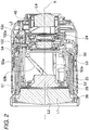
FIG. 2 is a vertical cross-sectional view showing a wide angle state of the lens barrel shown inFIG. 1 by a different vertical cross-section fromFIG. 1 , -
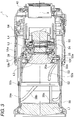
FIG. 3 is a cross-sectional view showing a telescopic state of the lens barrel shown inFIG. 1 , -
FIG. 4 is a perspective view showing a telescopic state in a fixed barrel, zoom drive barrel, and first group barrel in the lens barrel shown inFIG. 3 , -
FIG. 5 is a disassembled perspective view of a zoom drive barrel, zoom guide barrel, and drive pin holding member shown inFIG. 4 , -
FIG. 6 is a perspective view of a zoom drive barrel and zoom guide barrel shown inFIG. 4 , -
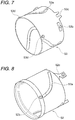
FIG. 7 is a perspective view of a zoom drive barrel shown inFIG. 6 , -
FIG. 8 is a perspective view of a zoom guide barrel shown inFIG. 6 , -
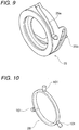
FIG. 9 is a perspective view of a focus lens frame shown inFIG. 1 to FIG. 3 , -
FIG. 10 is a perspective view of a drive pin holding member shown inFIG. 1 to FIG. 3 , -
FIG. 11 is a perspective view of a fixed barrel shown inFIG. 1 to FIG. 3 , -
FIG. 12 is a perspective view of a cam barrel positioned inside the fixed barrel shown inFIG. 11 and its contents, -
FIG. 13 is a perspective view of the cam barrel shown inFIG. 12 by itself, -
FIG. 14 is an unfolded view of a fixed barrel, zoom guide barrel, zoom drive barrel, cam groove barrel, focus lens frame, and first group barrel in the wide angle end state as seen from the outer circumference, -
FIG. 15 is an unfolded view of a fixed barrel, zoom guide barrel, zoom drive barrel, cam groove barrel, focus lens frame, and first group barrel in the telescopic end state as seen from the outer circumference, -
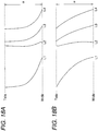
FIG. 16A is an unfolded view extracting the principal parts ofFIG. 14 , -
FIG. 16B is an unfolded view extracting the principal parts ofFIG. 15 , -
FIG. 17A is a schematic view extracting the three cam grooves and drive pins inFIG. 16A , -
FIG. 17B is a schematic view extracting the three cam grooves and drive pins inFIG. 16B , -
FIG. 18A is a view of the paths of movement of lens groups from a zoom wide angle ends (Wide) to a zoom telescopic end (Tele) found by optical design, -
FIG. 18B is a view of the paths of movement of lens groups from a zoom wide angle end (Wide) to a zoom telescopic end (Tele) due to the corrected cam groove shapes, -
FIG. 19 is a view of the amounts of movement of a focus lens frame at different zoom positions from a zoom wide angle end to a zoom telescopic end, -
FIG. 20 is a graph showing the relationship between an amount of movement of a focus lens frame at different zoom positions and a rotational angle of a focus operation ring, -
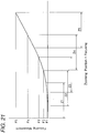
FIG. 21 is a graph showing the amount of movement of a focus lens frame at a zoom position as one curve with a shifted origin, and -
FIG. 22 is a graph showing the relationship between the focal distance of a lens barrel and the rotational angle of a zoom operation ring according to the present embodiment. - As shown in
FIG. 1 to FIG. 3 , thelens barrel 1 in the present embodiment is an exchangeable lens unit having an imaging optical system formed by four lens groups comprised of a first lens group L1, second lens group L2, third lens group L3, and fourth lens group L4 and operating to continuously change the focal distance (zoom operation). - The first lens group L1 to fourth lens group L4 all engage in independent advancing motion in the optical axis direction due to a zoom operation. The
lens barrel 1 in the present embodiment is a lens barrel of the so-called inner focus system. At the time of a focus operation, only the second lens group L2 advances in the optical axis direction. The second lens group L2 corresponds to the focus lens. - The image capturing optical system of the present embodiment is a lens system changing in the necessary amount of feed of the second lens group L2 at the time of a focus operation in accordance with the zoom position of the imaging optical system (focal distance). The second lens group L2 is fixed to a
focus lens frame 25 shown inFIG. 9 . Thislens frame 25 is formed with focus cam grooves (also called "focus cams") 25a. - The
focus cam grooves 25a correct the required amount of feed of the second lens group L2, which changes in accordance with the zoom position of the imaging optical system, so as to maintain the focusing state even when the zoom position changes and makes corrections for performing a feed operation for the second lens group L2 by a fixed amount of rotational operation (below also called simply "feed correction"). This feed correction is realized by thelens barrel 1 of the present embodiment. - The
lens barrel 1, to hold the first lens group L1 to fourth lens group L4 in a movable manner, as shown inFIG. 1 to FIG. 13 , has a fixedbarrel 50,zoom operation ring 51,zoom drive barrel 53,zoom guide barrel 52,cam barrel 24, focuslens frame 25, drivepin holding member 28, focus cam pins (drive cam pins) 101,first group barrel 38, etc. - The fixed
barrel 50 is a barrel shaped member not moving with respect to a not shown camera body during a zoom operation and during a focus operation and has grooves parallel to the optical axis direction of the imaging optical system comprised of the fixedbarrel advancing grooves 50a and fixedbarrel cam grooves 50b. The fixedbarrel 50 has alens mount 40 fixed to it. Thelens mount 40 is detachably attached to the not shown cam groove body. - Note that unless particularly alluded to otherwise, in the following explanation, movement in the direction parallel to the optical axis X of the imaging optical system based on the fixed
barrel 50 will be called "advance". Further, "rotation" will indicate rotation about the optical axis X. Further, the direction parallel to the optical axis X of the imaging optical system and moving away from thelens mount 40 will be called the "front (object side)" and the one moving close to thelens mount 40 will be called the "rear (image plane side)". - The
zoom operation ring 51 is a member rotating due to a rotational drive force by direct manual operation of the photographer at the time of a zoom operation. As shown inFIG. 3 , thezoom operation ring 51 is formed at its inner circumference with grooves parallel to the optical axis direction comprised of a plurality of advancinggrooves 51a at approximately equal intervals in the circumferential direction. Thezoom operation ring 51 in the present embodiment turns in a range of an angle α from a wide angle end to a telescopic end (seeFIG. 16A, 16B andFIG. 17A ). - As shown in
FIG. 4 to FIG. 8 , thezoom drive barrel 53 rotates with respect to azoom guide barrel 52 arranged at its inner circumference side, but does not move in the optical axis X direction. It is attached rotatably to the outer circumference of thezoom guide barrel 52 to advance together with it. Thezoom drive barrel 53, as shown inFIG. 3 , is formed with a plurality of drive force transmission pins 53b, engaging with the advancinggrooves 51a formed at the inner circumference of thezoom operation ring 51, at approximately equal intervals in the circumferential direction at the outer circumference of the rear end side of thedrive barrel 53. - These transmission pins 53b transmit the rotational drive force from the
zoom operation ring 51 to thezoom drive barrel 53. In accordance with thezoom operation ring 51, thezoom drive barrel 53 rotates in the range of the angle α from the wide angle end to the telescopic end. - As shown in
FIG. 1 andFIG. 4 andFIG. 7 , thezoom drive barrel 53 hasdrive grooves 53c parallel to the optical axis at the outer circumference at the rear end side. The advancinggrooves 53c engage with the cam barrel pins 100 shown inFIG. 1 ,FIG. 4 ,FIG. 11 , andFIG. 12 . The cam barrel pins 100, as shown inFIG. 12 , are fastened to thecam barrel 24. - As shown in
FIG. 4 andFIG. 7 , thezoom drive barrel 53 is formed with a plurality of (in the figure, three)correction cam grooves 53a at equal intervals in the circumferential direction. Thecorrection cam grooves 53a are formed in the range of the angle δ shown inFIG. 17A . - Each
correction cam groove 53a engages with one of the plurality of focus cam pins 101 (three in the illustration) formed at approximately equal intervals at outer circumferential positions of the drivepin holding member 28 shown inFIG. 10 . Eachcorrection cam groove 53a passes through thedrive barrel 53 between the inner and outer circumferences. - As shown in
FIG. 6 andFIG. 7 , thezoom drive barrel 53 is formed with a plurality of front cam pins 53d at its outer circumference in the front in the optical axis direction. The cam pins 53d engage with the first groupbarrel cam grooves 38b formed at the inner circumference side of thefirst group barrel 38 shown inFIG. 3 so as not to pass through to the inner circumference side. The first groupbarrel cam grooves 38b are formed at a slant with respect to the optical axis X direction. - As shown in
FIG. 3 , thefirst group barrel 38 is formed at its inner circumference side with a plurality of first groupbarrel guide grooves 38a parallel to the optical axis X at approximately equal intervals in the circumferential direction. These guidegrooves 38a do not pass through thefirst group barrel 38 from the inner circumference to the outer circumference like thecam grooves 38b. Theguide grooves 38a engage with guide pins 52b shown inFIG. 3 andFIG. 8 . - By the
drive barrel 53 being rotated about the optical axis X with respect to theguide barrel 52, the cam pins 53d move in thecam grooves 38b and the not rotating guide pins 52b move in theguide grooves 38a. For this reason, thefirst group barrel 38 can advance or retract with respect to thedrive barrel 53 and guidebarrel 52. Note that thefirst group barrel 38 has the lens group L1 fixed to it. - The
zoom guide barrel 52, as shown inFIG. 8 , is formed with a plurality ofzoom cam grooves 52a at equal intervals in the circumferential direction so as to pass between the inner and outer circumferential surfaces. Thezoom cam grooves 52a, as shown inFIG. 17A and FIG. 17B , are formed in a range of the angle γ. In the present embodiment, the sum of the angle γ of thecam grooves 52a and the angle δ of thecam grooves 53a is the range of rotation of the zoom operation ring 51 (drive barrel 53) and corresponds to the angle α from the wide angle end to the telescopic end. That is, thecam grooves 52a and thecam grooves 53a define the rotational angle of thedrive barrel 53 about the X-axis. - Each
cam groove 52a, together with eachcam groove 53a, is engaged with afocus cam pin 101 shown inFIG. 10 . At the rear end side of theguide barrel 52 in the optical axis X direction, as shown inFIG. 2 andFIG. 8 ,rear projections 52c are formed thickly at the inside diameter side of theguide barrel 52 from the barrel shaped part in the circumferential direction at a plurality of positions. - Each
rear projection 52c, as shown inFIG. 2 , has a zoomguide barrel pin 102 fastened to it through aboss 102a. The guide barrel pins 102, as shown inFIG. 4 , engage with the fixedbarrel advancing grooves 50a of the fixedbarrel 50 positioned at the inner circumferential side of theguide barrel 52. Therefore, theguide barrel 52 to which the guide barrel pins 102 are fixed does not rotate with respect to the fixedbarrel 50 and only advances along the advancinggrooves 50a. Thedrive barrel 53 arranged at the outer circumference of theguide grooves 52 rotates about the optical axis X without moving relative to theguide barrel 52 in the optical axis X direction. - By rotation of the
drive barrel 53, thepins 100 engaged with thedrive grooves 53c are made to move along the fixedbarrel cam grooves 50b formed passing through the fixedbarrel 50 and thecam barrel 24 to which thepins 100 are fixed is made to rotate about the optical axis X and is made to move in the optical axis X direction. Thecam barrel 24, as shown inFIG. 12 and FIG. 13 , is formed with third grouplens cam grooves 24a and fourth grouplens cam grooves 24b passing between the inner and outer circumferential surfaces. - The third group
lens cam grooves 24a, as shown inFIG. 12 , engage with zoom guide barrel pins 102. Thepins 102 are fixed to a third lens holding barrel holding the third lens group L3 shown inFIG. 1 to FIG. 3 . The third lens holding barrel holding the third lens group L3 is provided with a not shown advancing guide and prevented from rotating. For this reason, rotation of thedrive barrel 53 causes thepins 100 to also rotate. Along with this, thecam barrel 24 is also made to rotate and move in the optical axis direction. At this time, the third lens holding barrel holding the third lens group L3 moves in the optical axis X direction without rotation due to the action of thecam grooves 24a. - The fourth group
lens cam grooves 24b formed at thecam barrel 24 are engaged with fourth group drive pins fixed to the outer circumference of a fourth lens holding barrel holding the fourth lens group L4 arranged at the inner circumference of the rear end side of thecam barrel 24. Further, the fourth lens holding barrel holding the fourth lens group L4 is provided with a not shown advancing guide and is prevented from rotation. For this reason, in accordance with the rotation and advance of thecam barrel 24, due to the action of thecam grooves 24b, the fourth lens holding barrel holding the fourth lens group L4 moves in the optical axis X direction without rotation. - The fourth lens group L4 and the third lens group L3 are supported at the
cam barrel 24 arranged at the inner circumferential side of the fixedbarrel 50, so are structured to be resistant to deviation from the optical axis. Further, in the front of the third lens holding barrel holding the third lens group L3 and at the rear of the second lens group L2 (image plane side), a vibration reduction system VR shown inFIG. 11 is arranged. The vibration reduction system VR eliminates the effects of the vibration of thelens barrel 1 at the image plane side of the second lens group L2. - As shown in
FIG. 1 to FIG. 3 , thefocus lens frame 25 shown inFIG. 9 is arranged at the outer circumferential side of the front of the fixedbarrel 50 and the inner circumferential side of theguide barrel 52. Thelens frame 25, as shown inFIG. 1 to FIG. 3 , has the second lens group L2 fixed to it. Thelens frame 25 is formed withfocus cam grooves 25a at a plurality of positions at equal intervals in the circumferential direction. Thecam grooves 25a pass through thelens frame 25 between the inner and outer circumferential surfaces. - At the rear end side of the
lens frame 25 in the optical axis X direction, there is a driveforce transmission part 25b (seeFIG. 9 ) receiving rotational drive force (focus drive force) selectively from a not shown focus motor or focusoperation ring 54. The driveforce transmission part 25b has not a shown pin for transmitting the focus drive force engaged with it, but at the time of a zoom operation, this not shown pin is designed not to rotate by the drive resistance force imparted to the focus motor and focusoperation ring 54. That is, at the time of zoom operation, the second lens group L2 held at thelens frame 25 moves in the optical axis X direction without rotating about the optical axis X. - The
cam grooves 25a of thelens frame 25 have the focus cam pins 101 formed at the outer circumference of the drivepin holding member 28 arranged at the inner circumference side of thelens frame 25 engaged with them. The drivepin holding member 28 is not connected in any way with the fixedbarrel 50 and is in a floating state at a position in front of the fixedbarrel 50. - The drive
pin holding member 28, as shown inFIG. 10 , is preferably ring shaped, but may also be another shape. Note that as shown inFIG. 10 , three focus cam pins 101 are integrally provided at the drivepin holding member 28, so inclination of the focus cam pins 101 and phase deviation between the focus cam pins 101 are prevented. - Further, the drive
pin holding member 28 has an outside diameter smaller than the inside diameter of the fixedbarrel 50, so in the wide angle end state where the total length of thelens barrel 1 becomes short (seeFIG. 1 ), the focus pins 101 enter thenotches 50c provided in the fixed barrel 50 (seeFIG. 11 ) and the drivepin holding member 28 can be fit inside the fixedbarrel 50, so the lens barrel can be made smaller. - The focus cam pins 101 fixed to the drive
pin holding member 28, as shown inFIG. 3 , pass through thecam grooves 25a of thelens frame 25 and engage with thecam grooves 52a of theguide barrel 52 positioned at the outer circumferential side and thecam grooves 53a of thedrive barrel 53 positioned at the outer circumference of that. That is, thepins 101 simultaneously engage with the threecam grooves member 28 formed with thepins 101 can rotate independently with respect to the fixedbarrel 50,lens frame 25,guide barrel 52, and drivebarrel 53 and can move in the optical axis X direction. - Next, the operation of the lens barrel of the present embodiment will be explained.
- If operating the
zoom operation ring 51 shown inFIG. 1 to FIG. 3 to drive the rotation of thedrive barrel 53, the positional relationship between thepins 101 and the threecam grooves FIG. 14 to FIG. 15 , the state ofFIG. 16A to FIG. 16B , or the state ofFIG. 17A to FIG. 17B , that is, the wide angle end state, to the telescopic end state. Opposite movement is also possible. - If using the
zoom operation ring 51 shown inFIG. 1 to rotate thedrive barrel 53 from the wide angle end to the telescopic end by the angle α, the cam barrel pins 100 engaged with thedrive grooves 53c of thedrive barrel 53 also are rotated by the angle α. The cam barrel pins 100 are provided at thecam barrel 24 and are engaged with the fixedbarrel cam grooves 50b as well, so thecam barrel 24 advances while rotating by the angle α in accordance with the fixedbarrel cam grooves 50b. - The third group
lens cam grooves 24a provided at thecam barrel 24 are engaged with the zoom guide barrel pins 102, so thezoom guide barrel 52 and third lens group L3 advance by the amount of movement of the sum of the amount of movement in the advancing direction due to thecam grooves 24a and the amount of advancing movement of thecam barrel 24 itself. Further, thezoom guide barrel 52 advances, so thezoom drive barrel 53 attached to its outer circumference also advances while rotating together with thezoom guide barrel 52. - The fourth lens group L4 is restricted from rotation by the advancing guide pins from the third lens group L3, and the fourth group use drive pins engage with the fourth group
lens cam grooves 24b provided at thecam barrel 24. Therefore, the fourth lens group L4 advances by the amount of movement of the sum of the amount of movement in the advancing direction due to thecam grooves 24b and the amount of advancing movement of thecam barrel 24 itself. - In the
first group barrel 38, as explained above, the first groupbarrel guide grooves 38a are restricted from rotation by the guide pins 52b, and the cam pins 53d and the first groupbarrel cam grooves 38b are engaged. Therefore, as explained above, when thezoom guide barrel 52 advances and thezoom drive barrel 53 rotates while advancing, thefirst group barrel 38 advances by the amount of movement of the amount of advancing movement of thezoom guide barrel 52 andzoom drive barrel 53 and the amount of movement by the first groupbarrel cam grooves 38b together with the first lens group L1. - The focus cam pins 101 advance while the
zoom guide barrel 52 advances and thezoom drive barrel 53 advances while rotating, so the position where the correctionuse cam grooves 53a and thezoom cam grooves 52a switch, in other words, the position determined by the combination of thecorrection cam grooves 53a and thezoom cam grooves 52a moves. That is, the zoom operation is performed and the amount of that zoom operation is determined by the combination or coordination of thecorrection cam grooves 53a andzoom cam grooves 52a. - The
focus lens frame 25, as explained above, is restricted from rotation so as not to rotate at the time of zoom operation, so advances without rotation along with movement of the focus cam pins 101. - Here, the functions of the focus cam pins 101, focus
cam grooves 25a,correction cam grooves 53a, andzoom cam grooves 52a will be explained based onFIG. 17A and FIG. 17B. FIG. 17A shows the wide angle end state, whileFIG. 17B shows the telescopic end state. - The
focus cam grooves 25a are cam grooves correcting the amount of feed of the second lens group L2 and cam grooves adjusting the focus at the zoom position. As shown inFIG. 17A and FIG. 17B , the range of relative movement of the focus cam pins 101 due to the focus operation (what actually rotates in the focus operation is the focus lens frame 25) is a range of an angle β. This angle β does not change at the zoom positions from the wide angle end to the telescopic end. - The focusing is performed by selectively transmitting a rotational drive force (focus drive force) from a not shown focus motor or focus
operation ring 54 to a driveforce transmission part 25b provided at a rear end side of thelens frame 25 in the optical axis X direction (seeFIG. 9 ). As a result, thelens frame 25 rotates with respect to the cam pins 101 along thecam grooves 25a. For this reason, thelens frame 25 moves relative to theguide barrel 52 in the X-axial direction, the second lens group L2 is made to move relative to the first lens group L1 in the X-axial direction, and a focusing operation becomes possible. - However, the curves of the cam grooves with respect to the
pins 101 at thecam grooves 25a in the range of the angle β at the different zoom position changes. For example, inFIG. 19 , when the wide angle end zoom position is Z1 and the telescopic end zoom position is Z5, the intermediate positions are designated as Z2 to Z4. - At the wide angle end zoom position Z1, to focus from infinity to the nearest distance, focusing becomes possible in the range of the focus adjustment angle β by moving the second lens group L2 by the amount of movement F1. Further, at the telescopic end zoom position Z5, to focus from infinity to the nearest distance, focusing becomes possible in the range of the focus adjustment angle β by moving the second lens group L2 by the amount of movement F5. Further, at the intermediate zoom positions Z2 to Z4, for focusing from infinity to the nearest distance, focusing becomes possible in the range of the focus adjustment angle β by moving the second lens group L2 by the amounts of movement F2 to F4. These relationships are graphed separately in
FIG. 20 to FIG. 21 . - For such a design, to design the
focus cam grooves 25a, the shapes of thefocus cam grooves 25a are designed as follows. That is, as shown inFIG. 17A , at the wide angle end side, the angles of inclination of thecam grooves 25a are designed small so that even if the cam pins 101 move relatively in the focus adjustment angle β, the amount of movement of the focus lens frame 25 (that is, second lens group L2) in the optical axial direction will become relatively small. - Further, as shown in
FIG. 17B , at the telescopic end side, the angles of inclination of thecam grooves 25a are designed large so that even if the cam pins 101 move relatively in the focus adjustment angle β, the amount of movement of the focus lens frame 25 (that is, second lens group L2) in the optical axial direction will become relatively large. - As the zoom power becomes greater, in the past, the lengths of the cam grooves for moving the lens groups L1 to L4 became longer and the lengths of the
focus cam grooves 25a in which the cam pins 101 were engaged also had to be designed longer. However, there is a limit to the lengths of thefocus cam grooves 25a able to be formed at thelens frame 25 holding the lens group L2. They cannot be made that long. - Therefore, in the present embodiment, as explained above, the cam pins 101 are made able to move in the axial direction and rotate independent from the
lens frame 25, fixedbarrel 40,drive barrel 53, and guidebarrel 52 and further the cam pins 101 are made to simultaneously engage with thecam grooves FIG. 1 to FIG. 3 is equal to the rotational angle of thedrive barrel 53. Further, that zoom operation angle α becomes the total of the angle range γ of thecam grooves 52a and the angle range δ of thecam grooves 53a. - That is, the wide angle end position (Wide) at the time of a zoom operation is defined when the cam pins 101 are positioned at one end side of the
cam grooves 52a, while the telescopic position (Tele) at the time of the zoom operation is defined when the cam pins 101 are positioned at the other end side of thecam grooves 52a. Further, similarly, the wide angle end position (Wide) at the time of a zoom operation is defined when the drive cam pins 101 are positioned at one end side of thecam grooves 53a, while the telescopic position (Tele) at the time of the zoom operation is defined when the cam pins 101 are positioned at the other end side of thecam grooves 53a. - Therefore, in the present embodiment, even if the zoom operation angle α corresponding to the angle of rotational movement of the
drive barrel 53 is made relatively large, the movement of the cam pins 101 in thefocus cam grooves 25a from the wide angle end to the telescopic end can be reduced and therefore the length of thefocus cam grooves 25 in the longitudinal direction can be made shorter. - Note that as shown in
FIG. 3 , in a zoom operation, at least parts of thecam grooves 52a are positioned at the front (object side) from the second lens group L2. For this reason, the distance between the first lens group L1 and second lens group 2 can be made larger and the zoom power can be made larger. - That is, due to the zoom operation, the
zoom drive barrel 53 rotates in the range of the zoom operation angle α, but the range of the angle by which the focus cam pins 101 move, determined by the combination of thecam grooves 53a and thecam grooves 52a, becomes smaller than the range of the zoom operation angle α, in the present embodiment, the same as the angle range γ of thecam grooves 52a. - Further, in the
lens barrel 1 according to the present embodiment, the drivepin holding member 28 at which the cam pins 101 for simultaneously engaging with thecam grooves barrel 50, focuslens frame 25,zoom guide barrel 52, and drivebarrel 53. That is, the drivepin holding member 28 is arranged independently so as to be able to rotate about the optical axis X and move in the optical axis X direction with respect to the fixedbarrel 50, focuslens frame 25,zoom guide barrel 52, and drivebarrel 53. For this reason, even if a zoom operation causes thelens frame 25,zoom guide barrel 52, and drivebarrel 53 to move greatly with respect to the fixedbarrel 50 in the optical axis X direction, the drivepin holding member 28 also can move while rotating in the optical axis direction tracking this. - As a result, even if giving priority to the design of the shape of the
focus cam grooves 25a mainly used for adjusting the focus at the different zoom positions, the groove shapes of thezoom cam grooves 52a andcorrection grooves 53a used mainly for the high power zoom operation no longer become too sharp. For this reason, even a high powerzoom lens barrel 1 can perform a smooth zoom operation and focus operation and thebarrels cam grooves lens barrel 1 as a whole can be made compact. - Further, in the present embodiment, even if arranging a vibration reduction system VR at the image plane side of the second lens group L2, there is no need to make the cam groove mechanism for realizing a high power large at the outside. In this respect as well, the
lens barrel 1 as a whole can be made compact. Further, since the cam groove mechanism is not complicated, this also contributes to a reduction in the number of parts. - In particular, in the present embodiment, by making the
cam grooves 53a non-straight nonlinear shapes and providing bent parts in the middle of thegrooves 53a in the longitudinal direction, it is possible to finely control the movement of the relative position of the cam pins 101 in thecam grooves 25a while rotating thedrive barrel 53 from the wide angle end to the telescopic end. Further, by making the shapes nonlinear, the ratio of change of the focal distance of the lens groups L1 to L2 with respect to the rotational angle of theoperation ring 51 for controlling the zoom power can be finely adjusted at the wide angle mode and at the telescopic mode, so the use becomes easier. - Further, in the present embodiment, the zoom operation angle α can be made relatively large, so the curve of the
focus cam grooves 25 can be made much gentler and the drive force required for the focus operation can be reduced. - To change the zoom power from the wide angle end (Wide) to the telescopic end (Tele) or vice versa while maintaining the focus, in the optical design, it is necessary to make the lens groups L1 to L4 shown in
FIG. 1 to FIG. 3 move by the paths of movement shown in for exampleFIG. 18A . Further, in the optical design, as shown by the curve C2 shown inFIG. 22 , if changing the zoom operation angle from 0 to the maximum angle α=80 degrees, it is changed to give the focal distance of the illustrated abscissa at the different positions of the zoom operation angle (ordinate). - However, in such optical design, in practice, design of the
cam grooves FIG. 17A and FIG. 17B is sometimes difficult. Further, in the paths of movement of the lens groups L2, L3 shown inFIG. 18A , the distance between these lens groups L2, L3 is narrow, so that the vibration reduction system VR shown in for exampleFIG. 11 is difficult to be placed between these lens groups L2, L3. Further, as shown by the curve C1 ofFIG. 22 , at the wide angle end side, it is desired to make the change of the focal distance smaller with respect to a change in the rotational angle of the zoom operation angle, while at the telescopic side, it is desired to make the change of the focal distance larger with respect to a change in the rotational angle of the zoom operation angle, that is, there are demands for improving the user friendliness in this and other ways. - In the present embodiment, by realizing the groove shapes of the
cam grooves FIG. 17A and FIG. 17B , the paths of movement of the lens groups L1 to L4 are made the paths of movement as shown inFIG. 18A with respect to a change in rotational angle of the zoom operation angle. As a result, a change in the focal distance is realized with respect to a change in the rotational angle of the zoom operation angle shown by the curve C1 ofFIG. 22 . - That is, in the present embodiment, priority is given to the determination of the shapes of the
focus cam grooves 25a, so even if making thecorrection cam grooves 53a linear cam groove shapes, the amounts of movement of the first lens group L1, third lens group L3, and fourth lens group L4 become larger at the telescopic side than the wide angle side. As a result, the fixedbarrel cam grooves 50b end up much larger in gradient near the telescopic side. - Therefore, in the present embodiment, the
correction cam grooves 53a are made nonlinear cam groove shapes and the amounts of movement of the first lens group L1, third lens group L3, and fourth lens group L4 with respect to the rotational angle of the zoom operation of thezoom operation ring 51 are prevented from changing much due to the zoom position. That is, the amount of rotation in the range of use near the telescopic end of the fixedbarrel cam grooves 50b is made to appear larger than the range of use near the wide angle end. For this reason, the gradients of the fixedbarrel cam grooves 50b are prevented from partially greatly increasing and a smooth drive operation is possible at any zoom position. - Note that even if giving priority to the determination of the shapes of the fixed
barrel cam grooves 50b, if ending up making thecorrection cam grooves 53a linear cam groove shapes, the gradients of thefocus cam grooves 25a will partially increase by an extreme amount and the focus precision will end up being detrimentally affected. Therefore, thecorrection cam grooves 53a are preferably made nonlinear cam groove shapes. Further, thezoom cam grooves 52a also preferably are made nonlinear. - Further, in the present embodiment, as shown in
FIG. 12 and FIG. 13 , by making the thirdgroup cam grooves 24a of thecam barrel 24 not grooves parallel to the rotational direction, but cam groove shapes driving the zoom guide barrel pins 102 in the optical axis direction, the amount of movement for making thezoom guide barrel 52 and third lens group L3 advance is shared with the thirdgroup cam grooves 24a. Due to this, the amount of movement for making thecam barrel 24 advance handled by the fixedbarrel cam grooves 50b can be reduced and the gradients of the fixedbarrel cam grooves 50b can be made gentler. - According to the present embodiment, even a lens barrel driving a high power imaging optical system for a zoom operation can smoothly operate for a zoom operation and focus operation.
- Further, the outside diameter of the drive
pin holding member 28 is smaller than the inside diameter of the fixedbarrel 50, so the lens barrel can be made smaller. - Further, the first lens group L1 and the second lens group L2 are supported by the
zoom guide barrel 52 fit in the fixedbarrel 50 so are structured to be resistant to deviation from the optical axis, while the third lens group L3 and the fourth lens group L4 are supported by thecam barrel 24 fit in the fixedbarrel 50, so are structured to be resistant to deviation from the optical axis. For this reason, while a high power zoom lens barrel in which the first lens group L1 to fourth lens group L4, that is, four lens groups, move, there is resistance to deviation from the optical axis in all of the lens groups and good optical performance can be maintained from the wide angle to telescopic end. - The invention is not limited to the embodiments explained above. Various changes and modifications are possible. These are also in the scope of the present invention.
- For example, in the embodiments, the example was shown of using the
correction cam grooves 53a and thezoom cam grooves 52a for both the operations of correcting the amount of feed and converting the rotational angle, but the invention is not limited to these. For example, the interaction of thesegrooves - Further, the embodiments were explained with reference to exchangeable lenses, but the invention is not limited to this. For example, they may also be applied to a cameras with a built-in lens where the lens cannot be detached from the imaging device or other imaging part.
-
- 1. A lens barrel comprising
a first moving barrel (25) having a first cam (25a) configured corresponding to a focusing operation and holding an optical system (L2) used in said focusing operation,
a second moving barrel (52) having a second cam (52a) and provided in relation to the first moving barrel (25), and
a third moving barrel (53) having a third cam (53a) configured corresponding to a zoom operation and able to move relative to a fixed barrel (50), wherein
said second cam (52a) corrects a position of said optical system (L2) in accordance with a drive operation of said third cam (53a). - 2. The lens barrel as set forth in
clause 1, wherein a vibration reduction system eliminating effects of vibration of said lens barrel is provided at an image plane side from said optical system (L2). - 3. The lens barrel as set forth in
clause 1 or 2, wherein a combination of said second cam (52a) and said third cam (53a) is used to perform said zoom operation. - 4. The lens barrel as set forth in any one of
clauses 1 to 3, wherein, at the time of a zoom operation, at least a part of said second cam (52a) is positioned further to an object side from said optical system. - 5. A lens barrel comprising
a first moving barrel (25) having a first cam (25a) and having an optical system (L2) used in a focusing operation,
a second moving barrel (52) having a second cam (52a) and holding the first moving barrel (25), and
a third moving barrel (53) having a third cam (53a) configured corresponding to a zoom operation and able to move relative to a fixed barrel (50), wherein
said first moving barrel (25) is able to move relative to said second moving barrel (52) at the time of a focusing operation of said optical system, and
said second cam (52a), together with said third cam (53a), define a rotational angle of said third moving barrel (53). - 6. The lens barrel as set forth in clause 5, wherein, at the time of a zoom operation, at least a part of said second cam (52a) is positioned further to an object side from said optical system (L2).
- 7. A lens barrel including
a first moving barrel (25) having an optical system (L2) used in a focusing operation and
a second moving barrel (52) having a second cam (52a) able to move said first moving barrel (25) corresponding to a zoom operation and, at the time of a zoom operation, having at least parts of said second cam (52a) positioned further to an object side from said optical system (L2). - 8. The lens barrel as set forth in clause 7, further including a third moving barrel (53) formed with a third cam (53a) cooperating with said second cam (52a) to determine an amount of a zoom operation at the time of a zoom operation.
- 9. A lens barrel including
a first moving barrel (25) holding an optical system (L2) used in a focusing operation,
a second moving barrel (52) provided at an outside of said first moving barrel (25), and
a third moving barrel (53) able to move relative to a fixed barrel (50) corresponding to a zoom operation, wherein
said second moving barrel (25) is able to move corresponding to said third moving barrel (53), and
said first moving barrel (25) is able to move relative to said second moving barrel (52) at the time of said focusing operation and is provided between said fixed barrel (50) and said third moving barrel (53). - 10. The lens barrel as set forth in clause 9, wherein, at the time of a zoom operation, at least a part of a second cam (52a) is positioned further to an object side from said optical system (L2).
- 11. A lens barrel including
a first moving barrel (25) holding an optical system (L2) used in a focusing operation and
a second moving barrel (52) having a cam (52a) and able to move in an axial direction of a fixed barrel (50) corresponding to a zoom operation, wherein
said first moving barrel (25) can move, independent of said fixed barrel (50), relative to said second moving barrel (52), and
said cam (52a) can move said first moving barrel (25) corresponding to a zoom operation. - 12. The lens barrel as set forth in clause 11, wherein, at the time of a zoom operation, at least a part of said cam (52a) is positioned further to an object side from said optical system (L2)
- 13. A lens barrel including
a first moving barrel (25) having a first cam (25a) and holding an optical system (L2) used for a focusing operation,
a second moving barrel (52) having a second cam (52a), and cam pins (101) engaging with said first cam (25a) and second cam (52a) and moving to predetermined positions along said second cam (52a) corresponding to a zoom operation, wherein
said first moving barrel (25) rotates relative to said cam pins (101) along said first cam (25a) at the time of said focusing operation so as to move relative to said second moving barrel (52). - 14. The lens barrel as set forth in clause 13, wherein, at the time of a zoom operation, at least a part of said second cam (52a) is positioned further to an object side from said optical system (L2) .
- 15. A method of operation of a lens barrel characterized by
using a first cam (25a) formed at a first moving barrel (25) holding an optical system (L2) used for a focusing operation to move said optical system (L2) and
using a second cam (52a) provided at a second moving barrel (52) provided in relation to said first moving barrel (25) and a third cam (53a) provided at a third moving barrel (53) able to move relative to a fixed barrel (50) to determine a position of said optical system (L2) at the time of a zoom operation. - 16. The method of operation of a lens barrel as set forth in clause 15, further comprising eliminating an effect of vibration of said lens barrel further at an image plane side from said optical system (L2).
- 17. The method of operation of a lens barrel as set forth in clause 15 or 16, further comprising using said second cam (52a) and said third cam (53a) in combination for said zoom operation.
- 18. The method of operation of a lens barrel as set forth in any one of clauses 15 to 17, further comprising positioning at least a part of said second cam (52a) at the time of a zoom operation further at an object side from said optical system (L2).
- 19. A method of operation of a lens barrel comprising
holding an optical system (L2) used for a focusing operation with a first moving barrel (25),
moving a second moving barrel (52) relative to said first moving barrel (25) so that said second moving barrel (52) is at the outside of said first moving barrel (25),
moving a third moving barrel (53) relative to a fixed barrel (50) corresponding to a zoom operation and moving said second moving barrel (52) corresponding to movement of said third moving barrel (53), and
providing said first moving barrel (25) between said fixed barrel (50) and said third moving barrel (53). - 20. The method of operation of a lens barrel as set forth in clause 19 further comprising positioning at least a part of a second cam (52a) provided at said second moving barrel at the time of a zoom operation further to an object side from said optical system (L2).
- 21. The method of operation of a lens barrel as set forth in clause 19, further comprising using a second cam (52a) provided at said second moving barrel and a third cam (53a) provided at said third moving barrel in combination for said zoom operation.
Claims (12)
- A lens barrel comprising
a fixed barrel (50),
a zoom operation ring (51) for manual operation,
a first moving barrel (25) having a first cam groove (25a) that is operable to perform a focusing operation and hold an optical system (L2) used for said focusing operation,
a second moving barrel (52) having a second cam groove (52a),
a third moving barrel (53) having a third cam groove (53a) operable to perform a zoom operation,
the third moving barrel (53) being formed with a plurality of drive force transmission pins (53b), engaging with advancing grooves (51a) parallel to the optical axis formed at the inner circumference of the zoom operation ring (51) and transmitting the rotational drive force from the zoom operation ring (51) to the third moving barrel (53);
a plurality of focus cam pins (101) fixed to a holding member (28) and adapted to engage with said first cam groove (25a), said second cam groove (52a) and said third cam groove (53a),
wherein
the focus cam pins (101) are able to move in the axial direction and rotate independent from the first moving barrel (25), fixed barrel (50), third moving barrel (53), and second moving barrel (52) and further the focus cam pins (101) are made to simultaneously engage with the first, second and third cam grooves (25a, 52a, and 53a), whereby the angle α of the zoom operation of the zoom operation ring (51) is equal to the rotational angle of the third moving barrel (53) and the zoom operation angle α is equal to the total of the angle range γ of the second cam groove (52a) and the angle range δ of the third cam groove (53a). - The lens barrel as set forth in claim 1, further comprising
a vibration reduction system adapted to eliminate effects of vibration of said lens barrel, the vibration reduction system being positioned toward an image plane side of said second lens group (L2). - The lens barrel as set forth in claim 1 or 2, wherein a combination of said second cam groove (52a) and said third cam groove (53a) is adapted to operate said zoom operation.
- The lens barrel as set forth in any one of claims 1 to 3, wherein at least a part of said second cam groove (52a) is positioned toward an object side of said second lens group (L2) at a time of a zoom operation.
- The lens barrel a set forth in any one of claims 1 to 4, wherein the second moving barrel is provided between the first moving barrel and the third moving barrel in a circumferential direction.
- The lens barrel as set forth in any one of claims 1 to 5, wherein the first moving barrel (25) is arranged at the inner circumferential side of the second moving barrel (52).
- The lens barrel as set forth in any one of claims 1 to 6, wherein said first moving barrel (25) is adapted to rotate relative to said plurality of focus cam pins (101), along said first cam groove (25a), so as to move relative to said second moving barrel (52) during a time of performing the focusing operation.
- The lens barrel as set forth in any preceding claim wherein the range of the angle by which the focus cam pins (101) move is determined by the combination of the first cam groove (25a), the second cam groove (52a) and the third cam groove (53a).
- A method of operation of a lens barrel according to claim 1.
- The method of operation of a lens barrel as set forth in claim 9, further comprising
eliminating an effect of vibration of said lens barrel toward an image plane side of said second lens group (L2). - The method of operation of a lens barrel as set forth in claim 9 or 10, further comprising
using said second cam groove (52a) and said third cam groove (53a) in combination for performing said zoom operation. - The method of operation of a lens barrel as set forth in any one of claims 9 to 11, further comprising
positioning at least a part of said second cam groove (52a), at the time of performing the zoom operation, toward an object side from said second lens group (L2).
Applications Claiming Priority (2)
| Application Number | Priority Date | Filing Date | Title |
|---|---|---|---|
| JP2005357099 | 2005-12-12 | ||
| EP06256317.6A EP1795935B1 (en) | 2005-12-12 | 2006-12-12 | Lens barrel and method of operation of lens barrel |
Related Parent Applications (1)
| Application Number | Title | Priority Date | Filing Date |
|---|---|---|---|
| EP06256317.6A Division EP1795935B1 (en) | 2005-12-12 | 2006-12-12 | Lens barrel and method of operation of lens barrel |
Publications (1)
| Publication Number | Publication Date |
|---|---|
| EP3285106A1 true EP3285106A1 (en) | 2018-02-21 |
Family
ID=37836676
Family Applications (2)
| Application Number | Title | Priority Date | Filing Date |
|---|---|---|---|
| EP17190384.2A Withdrawn EP3285106A1 (en) | 2005-12-12 | 2006-12-12 | Lens barrel and method of operation of lens barrel |
| EP06256317.6A Not-in-force EP1795935B1 (en) | 2005-12-12 | 2006-12-12 | Lens barrel and method of operation of lens barrel |
Family Applications After (1)
| Application Number | Title | Priority Date | Filing Date |
|---|---|---|---|
| EP06256317.6A Not-in-force EP1795935B1 (en) | 2005-12-12 | 2006-12-12 | Lens barrel and method of operation of lens barrel |
Country Status (2)
| Country | Link |
|---|---|
| US (1) | US7835085B2 (en) |
| EP (2) | EP3285106A1 (en) |
Families Citing this family (10)
| Publication number | Priority date | Publication date | Assignee | Title |
|---|---|---|---|---|
| JP4487216B2 (en) * | 2008-01-18 | 2010-06-23 | ソニー株式会社 | Lens barrel and imaging device |
| JP2011022566A (en) * | 2009-06-15 | 2011-02-03 | Panasonic Corp | Zoom lens and image capturing apparatus |
| CN102540388B (en) * | 2010-12-25 | 2013-10-09 | 鸿富锦精密工业(深圳)有限公司 | Combined Lens Barrel and Its Application Zoom Lens |
| JP5765617B2 (en) * | 2011-03-10 | 2015-08-19 | 株式会社リコー | Lens barrel, imaging device, information device, and image input device |
| CN102436050B (en) * | 2011-12-29 | 2013-07-03 | 中国科学院长春光学精密机械与物理研究所 | Automatic reciprocating cylindrical cam focusing mechanism |
| KR102072225B1 (en) | 2012-10-05 | 2020-02-03 | 삼성전자주식회사 | Zoom lens barrel assembly and photographing apparatus comprising the same |
| JP6478199B2 (en) * | 2014-02-28 | 2019-03-06 | 三星電子株式会社Samsung Electronics Co.,Ltd. | Lens barrel and optical equipment |
| JP6750883B2 (en) * | 2017-05-31 | 2020-09-02 | キヤノン株式会社 | Lens barrel and optical equipment |
| JP7218631B2 (en) | 2019-03-15 | 2023-02-07 | 株式会社リコー | Lens barrel and imaging device |
| CN115933101A (en) * | 2019-07-29 | 2023-04-07 | 青岛海信激光显示股份有限公司 | Projection lens and laser projection device |
Citations (7)
| Publication number | Priority date | Publication date | Assignee | Title |
|---|---|---|---|---|
| JPH07333482A (en) | 1994-06-07 | 1995-12-22 | Tamron Co Ltd | High-magnification zoom lens |
| JPH0868929A (en) * | 1994-08-31 | 1996-03-12 | Olympus Optical Co Ltd | Zoom lens barrel |
| JPH08136787A (en) * | 1994-11-04 | 1996-05-31 | Nikon Corp | Zoom lens barrel |
| JPH08304684A (en) * | 1995-04-28 | 1996-11-22 | Tamron Co Ltd | High-magnification zoom lens |
| US6381076B1 (en) * | 2000-09-26 | 2002-04-30 | Canon Kabushiki Kaisha | Zoom lens barrel |
| GB2372111A (en) * | 2001-02-09 | 2002-08-14 | Tamron Kk | High zoom ratio lens |
| US20030179467A1 (en) * | 2002-03-20 | 2003-09-25 | Satoshi Todani | High zoom ratio lens |
Family Cites Families (5)
| Publication number | Priority date | Publication date | Assignee | Title |
|---|---|---|---|---|
| JP3568307B2 (en) * | 1996-01-24 | 2004-09-22 | オリンパス株式会社 | Lens barrel cam mechanism |
| JP3882228B2 (en) * | 1996-07-05 | 2007-02-14 | 株式会社ニコン | Zoom lens barrel |
| JP3354406B2 (en) * | 1996-09-02 | 2002-12-09 | 富士写真光機株式会社 | Drive mechanism for taking lens |
| US6025964A (en) * | 1997-05-16 | 2000-02-15 | Canon Kabushiki Kaisha | Optical apparatus |
| JP4185729B2 (en) * | 2002-08-06 | 2008-11-26 | キヤノン株式会社 | Lens barrel and camera |
-
2006
- 2006-10-27 US US11/588,275 patent/US7835085B2/en not_active Expired - Fee Related
- 2006-12-12 EP EP17190384.2A patent/EP3285106A1/en not_active Withdrawn
- 2006-12-12 EP EP06256317.6A patent/EP1795935B1/en not_active Not-in-force
Patent Citations (7)
| Publication number | Priority date | Publication date | Assignee | Title |
|---|---|---|---|---|
| JPH07333482A (en) | 1994-06-07 | 1995-12-22 | Tamron Co Ltd | High-magnification zoom lens |
| JPH0868929A (en) * | 1994-08-31 | 1996-03-12 | Olympus Optical Co Ltd | Zoom lens barrel |
| JPH08136787A (en) * | 1994-11-04 | 1996-05-31 | Nikon Corp | Zoom lens barrel |
| JPH08304684A (en) * | 1995-04-28 | 1996-11-22 | Tamron Co Ltd | High-magnification zoom lens |
| US6381076B1 (en) * | 2000-09-26 | 2002-04-30 | Canon Kabushiki Kaisha | Zoom lens barrel |
| GB2372111A (en) * | 2001-02-09 | 2002-08-14 | Tamron Kk | High zoom ratio lens |
| US20030179467A1 (en) * | 2002-03-20 | 2003-09-25 | Satoshi Todani | High zoom ratio lens |
Also Published As
| Publication number | Publication date |
|---|---|
| EP1795935B1 (en) | 2017-09-13 |
| US7835085B2 (en) | 2010-11-16 |
| EP1795935A1 (en) | 2007-06-13 |
| US20070153403A1 (en) | 2007-07-05 |
Similar Documents
| Publication | Publication Date | Title |
|---|---|---|
| US6751031B2 (en) | Lens barrel capable of positioning lens frames with high precision | |
| JP4969859B2 (en) | Lens barrel | |
| JP2007219405A (en) | Lens barrel and camera system | |
| US6819502B2 (en) | Structure of a zoom lens barrel | |
| US8305696B2 (en) | Inner focusing zoom lens | |
| US12066687B2 (en) | Lens barrel and optical device | |
| EP1795935B1 (en) | Lens barrel and method of operation of lens barrel | |
| JP4684613B2 (en) | Optical equipment | |
| JP4899845B2 (en) | Lens barrel, lens barrel operating method, and camera system | |
| JPH07111498B2 (en) | Zoom lens barrel | |
| EP1808718A1 (en) | Compact zoom lens | |
| JP3416317B2 (en) | Lens barrel and optical equipment using the same | |
| JP2005352406A (en) | Zoom lens barrel | |
| KR100325181B1 (en) | Barrle assembly of zoom camera | |
| JP7360553B2 (en) | Zoom lens device and optical device | |
| JP2006065138A (en) | Lens driving device | |
| US7852569B2 (en) | Internal focusing zoom lens | |
| JP4623665B2 (en) | Lens barrel and optical device | |
| JP2006234962A (en) | Lens barrel | |
| JP7532081B2 (en) | Optical Instruments | |
| US20010019456A1 (en) | Zoom lens barrel and camera | |
| JP4444409B2 (en) | Zoom lens apparatus and optical apparatus equipped with the same | |
| JP2741239B2 (en) | Zoom lens barrel | |
| JP4373129B2 (en) | Zoom lens barrel | |
| JPH0933785A (en) | Zoom lens barrel |
Legal Events
| Date | Code | Title | Description |
|---|---|---|---|
| PUAI | Public reference made under article 153(3) epc to a published international application that has entered the european phase |
Free format text: ORIGINAL CODE: 0009012 |
|
| STAA | Information on the status of an ep patent application or granted ep patent |
Free format text: STATUS: THE APPLICATION HAS BEEN PUBLISHED |
|
| AC | Divisional application: reference to earlier application |
Ref document number: 1795935 Country of ref document: EP Kind code of ref document: P |
|
| AK | Designated contracting states |
Kind code of ref document: A1 Designated state(s): AT BE BG CH CY CZ DE DK EE ES FI FR GB GR HU IE IS IT LI LT LU LV MC NL PL PT RO SE SI SK TR |
|
| STAA | Information on the status of an ep patent application or granted ep patent |
Free format text: STATUS: REQUEST FOR EXAMINATION WAS MADE |
|
| 17P | Request for examination filed |
Effective date: 20180820 |
|
| RBV | Designated contracting states (corrected) |
Designated state(s): AT BE BG CH CY CZ DE DK EE ES FI FR GB GR HU IE IS IT LI LT LU LV MC NL PL PT RO SE SI SK TR |
|
| STAA | Information on the status of an ep patent application or granted ep patent |
Free format text: STATUS: EXAMINATION IS IN PROGRESS |
|
| 17Q | First examination report despatched |
Effective date: 20181105 |
|
| STAA | Information on the status of an ep patent application or granted ep patent |
Free format text: STATUS: THE APPLICATION IS DEEMED TO BE WITHDRAWN |
|
| 18D | Application deemed to be withdrawn |
Effective date: 20200701 |