EP3284915A1 - Steam turbine - Google Patents
Steam turbine Download PDFInfo
- Publication number
- EP3284915A1 EP3284915A1 EP15902199.7A EP15902199A EP3284915A1 EP 3284915 A1 EP3284915 A1 EP 3284915A1 EP 15902199 A EP15902199 A EP 15902199A EP 3284915 A1 EP3284915 A1 EP 3284915A1
- Authority
- EP
- European Patent Office
- Prior art keywords
- flow passage
- steam
- rotor blade
- gap
- row
- Prior art date
- Legal status (The legal status is an assumption and is not a legal conclusion. Google has not performed a legal analysis and makes no representation as to the accuracy of the status listed.)
- Granted
Links
Images


Classifications
-
- F—MECHANICAL ENGINEERING; LIGHTING; HEATING; WEAPONS; BLASTING
- F01—MACHINES OR ENGINES IN GENERAL; ENGINE PLANTS IN GENERAL; STEAM ENGINES
- F01D—NON-POSITIVE DISPLACEMENT MACHINES OR ENGINES, e.g. STEAM TURBINES
- F01D11/00—Preventing or minimising internal leakage of working-fluid, e.g. between stages
- F01D11/001—Preventing or minimising internal leakage of working-fluid, e.g. between stages for sealing space between stator blade and rotor
-
- F—MECHANICAL ENGINEERING; LIGHTING; HEATING; WEAPONS; BLASTING
- F01—MACHINES OR ENGINES IN GENERAL; ENGINE PLANTS IN GENERAL; STEAM ENGINES
- F01D—NON-POSITIVE DISPLACEMENT MACHINES OR ENGINES, e.g. STEAM TURBINES
- F01D9/00—Stators
- F01D9/02—Nozzles; Nozzle boxes; Stator blades; Guide conduits, e.g. individual nozzles
- F01D9/04—Nozzles; Nozzle boxes; Stator blades; Guide conduits, e.g. individual nozzles forming ring or sector
- F01D9/041—Nozzles; Nozzle boxes; Stator blades; Guide conduits, e.g. individual nozzles forming ring or sector using blades
-
- F—MECHANICAL ENGINEERING; LIGHTING; HEATING; WEAPONS; BLASTING
- F01—MACHINES OR ENGINES IN GENERAL; ENGINE PLANTS IN GENERAL; STEAM ENGINES
- F01D—NON-POSITIVE DISPLACEMENT MACHINES OR ENGINES, e.g. STEAM TURBINES
- F01D1/00—Non-positive-displacement machines or engines, e.g. steam turbines
- F01D1/02—Non-positive-displacement machines or engines, e.g. steam turbines with stationary working-fluid guiding means and bladed or like rotor, e.g. multi-bladed impulse steam turbines
-
- F—MECHANICAL ENGINEERING; LIGHTING; HEATING; WEAPONS; BLASTING
- F01—MACHINES OR ENGINES IN GENERAL; ENGINE PLANTS IN GENERAL; STEAM ENGINES
- F01D—NON-POSITIVE DISPLACEMENT MACHINES OR ENGINES, e.g. STEAM TURBINES
- F01D11/00—Preventing or minimising internal leakage of working-fluid, e.g. between stages
- F01D11/02—Preventing or minimising internal leakage of working-fluid, e.g. between stages by non-contact sealings, e.g. of labyrinth type
-
- F—MECHANICAL ENGINEERING; LIGHTING; HEATING; WEAPONS; BLASTING
- F01—MACHINES OR ENGINES IN GENERAL; ENGINE PLANTS IN GENERAL; STEAM ENGINES
- F01D—NON-POSITIVE DISPLACEMENT MACHINES OR ENGINES, e.g. STEAM TURBINES
- F01D11/00—Preventing or minimising internal leakage of working-fluid, e.g. between stages
- F01D11/02—Preventing or minimising internal leakage of working-fluid, e.g. between stages by non-contact sealings, e.g. of labyrinth type
- F01D11/04—Preventing or minimising internal leakage of working-fluid, e.g. between stages by non-contact sealings, e.g. of labyrinth type using sealing fluid, e.g. steam
-
- F—MECHANICAL ENGINEERING; LIGHTING; HEATING; WEAPONS; BLASTING
- F01—MACHINES OR ENGINES IN GENERAL; ENGINE PLANTS IN GENERAL; STEAM ENGINES
- F01D—NON-POSITIVE DISPLACEMENT MACHINES OR ENGINES, e.g. STEAM TURBINES
- F01D11/00—Preventing or minimising internal leakage of working-fluid, e.g. between stages
- F01D11/08—Preventing or minimising internal leakage of working-fluid, e.g. between stages for sealing space between rotor blade tips and stator
- F01D11/10—Preventing or minimising internal leakage of working-fluid, e.g. between stages for sealing space between rotor blade tips and stator using sealing fluid, e.g. steam
-
- F—MECHANICAL ENGINEERING; LIGHTING; HEATING; WEAPONS; BLASTING
- F01—MACHINES OR ENGINES IN GENERAL; ENGINE PLANTS IN GENERAL; STEAM ENGINES
- F01D—NON-POSITIVE DISPLACEMENT MACHINES OR ENGINES, e.g. STEAM TURBINES
- F01D25/00—Component parts, details, or accessories, not provided for in, or of interest apart from, other groups
-
- F—MECHANICAL ENGINEERING; LIGHTING; HEATING; WEAPONS; BLASTING
- F01—MACHINES OR ENGINES IN GENERAL; ENGINE PLANTS IN GENERAL; STEAM ENGINES
- F01D—NON-POSITIVE DISPLACEMENT MACHINES OR ENGINES, e.g. STEAM TURBINES
- F01D5/00—Blades; Blade-carrying members; Heating, heat-insulating, cooling or antivibration means on the blades or the members
- F01D5/02—Blade-carrying members, e.g. rotors
- F01D5/06—Rotors for more than one axial stage, e.g. of drum or multiple disc type; Details thereof, e.g. shafts, shaft connections
-
- F—MECHANICAL ENGINEERING; LIGHTING; HEATING; WEAPONS; BLASTING
- F05—INDEXING SCHEMES RELATING TO ENGINES OR PUMPS IN VARIOUS SUBCLASSES OF CLASSES F01-F04
- F05D—INDEXING SCHEME FOR ASPECTS RELATING TO NON-POSITIVE-DISPLACEMENT MACHINES OR ENGINES, GAS-TURBINES OR JET-PROPULSION PLANTS
- F05D2220/00—Application
- F05D2220/30—Application in turbines
- F05D2220/31—Application in turbines in steam turbines
-
- F—MECHANICAL ENGINEERING; LIGHTING; HEATING; WEAPONS; BLASTING
- F05—INDEXING SCHEMES RELATING TO ENGINES OR PUMPS IN VARIOUS SUBCLASSES OF CLASSES F01-F04
- F05D—INDEXING SCHEME FOR ASPECTS RELATING TO NON-POSITIVE-DISPLACEMENT MACHINES OR ENGINES, GAS-TURBINES OR JET-PROPULSION PLANTS
- F05D2240/00—Components
- F05D2240/55—Seals
-
- F—MECHANICAL ENGINEERING; LIGHTING; HEATING; WEAPONS; BLASTING
- F05—INDEXING SCHEMES RELATING TO ENGINES OR PUMPS IN VARIOUS SUBCLASSES OF CLASSES F01-F04
- F05D—INDEXING SCHEME FOR ASPECTS RELATING TO NON-POSITIVE-DISPLACEMENT MACHINES OR ENGINES, GAS-TURBINES OR JET-PROPULSION PLANTS
- F05D2240/00—Components
- F05D2240/60—Shafts
Definitions
- the present invention relates to a steam turbine which is driven by steam.
- a steam turbine includes a rotor which rotates about an axis and a casing which covers the rotor.
- the rotor includes a rotor shaft which extends in an axial direction about an axis and a plurality of stages of rotor blade rows which are fixed to an outer periphery of the rotor shaft and are arranged in the axial direction.
- the steam turbine includes a stator vane row which is fixed to an inner periphery of the casing and is disposed on an upstream side of each stage of the plurality of stages of rotor blade rows.
- a steam turbine of Patent Document 1 includes a ring-shaped protrusion which protrudes from a downstream side end surface of an inner ring provided on an inner peripheral side of a stator vane of a stator vane row toward a downstream side thereof.
- the steam turbine includes a ring-shaped protrusion which protrudes from an upstream side end surface of a tubular rotor blade support portion provided on an inner peripheral side of a rotor blade configuring a rotor blade row toward an upstream side thereof.
- the ring-shaped protrusion on the stator vane side is disposed on the outer peripheral side of the ring-shaped protrusion on the rotor blade side, and the protrusions are provided to overlap each other in an axial direction. Accordingly, a gap between the stator vanes and the rotor blades is bent in a crank shape, and thus, steam flowing through a steam main flow passage is prevented from leaking from a gap between the rotor blade rows and the stator vane rows toward the inner peripheral side.
- Patent Document 1 Japanese Unexamined Patent Application, First Publication No. 2015-25404
- the present invention provides a steam turbine capable of decreasing a leakage amount of steam flowing through the steam main flow passage and improving turbine efficiency.
- a steam turbine including: a rotor shaft which includes a shaft core portion which rotates about an axis and a disk portion which is fixed to the shaft core portion and expands toward a radially outer side in the shaft core portion; a plurality of rotor blade rows which are fixed to an outer periphery of the disk portion and are arranged in an axial direction in which the shaft core portion extends; and a stator vane row which is adjacent to an upstream side of the rotor blade row in the axial direction for each of the plurality of rotor blade rows, in which a gap flow passage, which extends toward a radially inner side from a steam main flow passage which extends in the axial direction and through which steam flows, is formed in a gap between the stator vane row and the rotor blade row configuring a speed governing stage disposed on the most upstream side among a plurality of stages configured by combinations of the rotor blade rows and the stator vane rows
- the steam turbine may further include a fin which is provided on the steam main flow passage side of the gap flow passage in the radial direction and extends from the rotor blade row toward the stator vane row.
- the fin is provided in the gap flow passage, and thus, an interval between the rotor blade row and the stator vane row of the speed governing stage is narrowed, and it is possible to further decrease an amount of steam flowing into the gap flow passage.
- a flow passage width of the gap flow passage may be larger than a gap between a tip portion of the fin and an end portion on a downstream side of the stator vane row and may be smaller than a gap between an end portion on an upstream side of the rotor blade row of the speed governing stage and an end portion on a downstream side of the stator vane row of the speed governing stage.
- the gap flow passage may include an outer peripheral side flow passage portion which extends from the steam main flow passage toward the radially inner side, an intermediate flow passage portion which is connected to the outer peripheral side flow passage portion and extends in the axial direction, and an inner peripheral side flow passage portion which extends from the intermediate flow passage portion toward the radially inner side.
- the gap flow passage is bent in a crank shape from the outer peripheral side toward the inner peripheral side, and thus, a flow passage resistance increases and it is possible to decrease the amount of the steam leaking out from the steam main flow passage.
- steam flows from the communication passage into the gap flow passage formed in the gap between the stator vane row and the rotor blade row configuring the speed governing stage. Therefore, it is possible to decrease a leakage amount of steam flowing into the steam main flow passage and it is possible to improve turbine efficiency.
- FIG. 1 is a sectional view of a steam turbine according to a first embodiment of the present invention.
- FIG. 2 is a view showing an attachment structure of a rotor blade to a disk portion in the steam turbine of the first embodiment of the present invention.
- FIG. 3 is a sectional view of a stator vane row and a rotor blade row of a speed governing stage in the steam turbine of the first embodiment of the present invention.
- a steam turbine 1 of the present embodiment includes a rotor 20 which rotates about an axis Ar and a casing 10 which covers the rotor 20 to be rotatable.
- a direction in which the axis Ar extends is referred to an axial direction Da
- a first side in the axial direction Da is referred to as an upstream side (one side, first side) Dau
- a second side in the axial direction Da is referred to as a downstream side (the other side, second side) Dad.
- a radial direction in a shaft core portion 22 described later based on the axis Ar is simply referred to a radial direction Dr
- a side close to the axis Ar in the radial direction Dr is referred to as a radially inner side Dri
- a side opposite to the radially inner side Dri in the radial direction Dr is referred to as a radially outer side Dro
- a circumferential direction of the shaft core portion 22 about the axis Ar is simply referred to as a circumferential direction Dc.
- the rotor 20 includes a rotor shaft 21 and a plurality of rotor blade rows 31 which are provided at intervals therebetween along the axial direction Da of the rotor shaft 21.
- the rotor shaft 21 includes a shaft core portion 22 which is formed in a columnar shape about the axis Ar, and extends in the axial direction Da and a plurality of disk portions 23 which extend from the shaft core portion 22 toward the radially outer side Dro and are arranged at intervals therebetween in the axial direction Da.
- the disk portion 23 is provided for each of the plurality of rotor blade rows 31.
- the rotor blade row 31 is attached to the outer periphery of the disk portion 23 which is an outer peripheral portion of the rotor shaft 21.
- the plurality of rotor blade rows 31 are provided at intervals therebetween along the axial direction Da of the rotor shaft 21.
- the number of the rotor blade rows 31 is seven. Accordingly, in the case of the present embodiment, as the rotor blade rows 31, first to seventh stages of rotor blade rows 31 are provided.
- the steam turbine 1 includes a plurality of stator vane rows 41 which are fixed to an inner periphery of the casing 10 and are provided at intervals therebetween along the axial direction Da.
- the stator vane row 41 is adjacent to an upstream side of the rotor blade row 31 in the axial direction Da for each of the plurality of rotor blade rows 31.
- the number of the stator vane rows 41 is seven which is the same as the number of the rotor blade rows 31. Accordingly, in the case of the present embodiment, as the stator vane rows 41, first to seventh stages of stator vane rows 41 are provided.
- Each of the plurality of stator vane rows 41 is disposed to be adjacent to the upstream side Dau with respect to the rotor blade row 31.
- a nozzle chamber 11 into which steam S flows from the outside, a steam main flow passage chamber 12 into which the steam S from the nozzle chamber 11 flows, and an exhaust chamber 13 to which the steam S which flows from the steam main flow passage chamber 12 is discharged are formed.
- the rotor blade row 31 and the stator vane row 41 which are positioned on the most upstream side Dau among the plurality of rotor blade rows 31 and stator vane rows 41, are disposed between the nozzle chamber 11 and the steam main flow passage chamber 12.
- the inside of the casing 10 is divided into the nozzle chamber 11 and the steam main flow passage chamber 12 by the rotor blade row 31 and the stator vane row 41 positioned on the most upstream side Dau.
- stator vane rows 41 and all the rotor blade rows 31 except for the rotor blade row 31 and the stator vane row 41 positioned on the most upstream side Dau among the plurality of rotor blade rows 31 and stator vane rows 41 are disposed.
- One stage 50 is formed for each combination of the rotor blade row 31 and the stator vane row 41 disposed to be adjacent to the upstream side Dau of the rotor blade row 31.
- the stator vane row 41 is provided with respect to each of seven rotor blade rows 31, and thus, seven stages 50 are provided. That is, the steam turbine 1 of the present embodiment includes a first stage 51, a second stage 52, a third stage 53, a fourth stage 54, a fifth stage 55, a sixth stage 56, and a seventh stage 57 in this order from the upstream side Dau.
- the first stage 51 which is positioned on the most upstream side among the plurality of stages 50 configures a speed governing stage 50a.
- the speed governing stage 50a regulates a flow rate of the steam S fed to the stage 50 positioned on the downstream side Dad from the speed governing stage 50a so as to adjust a rotating speed of the rotor 20.
- the second stage 52, the third stage 53, and the fourth stage 54 configure an intermediate pressure stage 50b.
- the fifth stage 55, the sixth stage 56, and the seventh stage 57 configure a low pressure stage 50c.
- stator vane row 41 of the first stage 51 configuring a portion of the speed governing stage 50a is referred to as a speed governing stage stator vane row 41a.
- the rotor blade row 31 of the first stage 51 configuring the other portion of the speed governing stage 50a is referred to as a speed governing stage rotor blade row 31a.
- stator vane row 41 of the second stage 52 to the stator vane row 41 of the fourth stage 54 configuring a portion of the intermediate pressure stage 50b are referred to as intermediate pressure stage stator vane rows 41b.
- the rotor blade row 31 of the second stage 52 to the rotor blade row 31 of the fourth stage 54 configuring the other portion of the intermediate pressure stage 50b are referred to as intermediate pressure stage rotor blade rows 31b.
- stator vane row 41 of the fifth stage 55 to the stator vane row 41 of the seventh stage 57 configuring a portion of the low pressure stage 50c are referred to as low pressure stage stator vane rows 41c.
- the rotor blade row 31 of the fifth stage 55 to the rotor blade row 31 of the seventh stage 57 configuring the other portion of the low pressure stage 50c are referred to as low pressure stage rotor blade rows 31c.
- the disk portion 23 of the rotor shaft 21 to which the speed governing stage rotor blade row 31a is fixed is referred to as a speed governing stage disk portion 23a.
- the disk portions 23 of the rotor shaft 21 to which the intermediate pressure stage rotor blade rows 31b are fixed are referred to as intermediate pressure stage disk portions 23b.
- the disk portions 23 of the rotor shaft 21 to which the low pressure stage rotor blade rows 31c are fixed are referred to as low pressure stage disk portions 23c.
- each rotor blade row 31 includes a plurality of rotor blades 32 which are arranged in the circumferential direction Dc.
- Each rotor blade 32 includes a blade body 33 which extends in the radial direction Dr, a shroud 34 which is provided on the radially outer side Dro of the blade body 33, a platform 35 which is provided on the radially inner side Dri of the blade body 33, and a blade root 36 (refer to FIG. 2 ) which is provided on the radially inner side Dri of the platform 35.
- a portion between the shroud 34 and the platform 35 configures a portion of the steam main flow passage 15 through which the steam S flows.
- the steam main flow passage 15 extends in the axial direction Da over the plurality of rotor blade rows 31 and the plurality of stator vane rows 41.
- the steam main flow passage 15 is formed in an annular shape around the rotor 20.
- axial fins (fins) 35Fa and 35Fb are provided in the speed governing stage rotor blade row 31a.
- the axial fins (fins) 35Fa and 35Fb are provided to face an opening of a gap flow passage 100A described later on the steam main flow passage 15 side in the radial direction Dr.
- the axial fins (fin) 35Fa and 35Fb extend from the speed governing stage rotor blade row 31a toward the speed governing stage stator vane row 41a.
- the axial fins (fins) 35Fa and 35Fb of the present embodiment are provided on the upstream side Dau of the platform 35 of the rotor blade 32 in the axial direction Da.
- the axial fin 35Fa is formed to protrude toward the upstream side Dau from the radially outer side Dro of an end surface 35u which is toward the upstream side Dau of the platform 35 in the axial direction Dau.
- the axial fin 35Fb is formed to protrude toward the upstream side Dau from the radially inner side Dri of the end surface 35u of the platform 35.
- the clearance between the end surface 35u of the platform 35 which is a front edge portion of the rotor blade 32 of the speed governing stage rotor blade row 31a and an inner ring 46 described later which is a rear edge portion of the stator vane 42 of the speed governing stage stator vane row 41a is narrowed by the axial fins 35Fa and 35Fb. Accordingly, the axial fin 35Fa and the axial fin 35Fb prevent the steam S from leaking toward the radially inner side Dri from the steam main flow passage 15 extending in the axial direction Da toward the gap between the speed governing stage rotor blade row 31a and the speed governing stage stator vane row 41a.
- the blade root 36 is fitted into a blade groove 28 formed on an outer peripheral portion of the disk portion 23 in the rotor shaft 21.
- each rotor blade row 31 the blade root 36 of each rotor blade 32 is formed to extend from a platform inner peripheral surface 35f which is toward the radially inner side Dri of the platform 35 toward the radially inner side Dri.
- the blade root 36 includes a blade root body 37 which extends from the platform inner peripheral surface 35f toward the radially inner side Dri and an engaging protrusion portion 38 which protrudes from the blade root body 37 toward both sides in the circumferential direction Dc.
- the engaging protrusion portion 38 protrudes from the blade root body 37 at a plurality of locations spaced apart along the radial direction Dr.
- the engaging protrusion portion 38 engages with an engaging recessed portion 29 described later which is formed on the blade groove 28.
- the engaging protrusion portion 38 is formed at three locations spaced apart along the radial direction Dr.
- Each of engaging protrusion portions 38A, 38B, and 38C has a curved surface shape which protrudes in a direction separated from the center in the circumferential direction Dc of the blade root 36 along the circumferential direction Dc in each of one side and the other side of the blade root 36 in the circumferential direction Dc.
- the engaging protrusion portion 38B and the engaging protrusion portion 38C disposed on the radially inner side Dri of the engaging protrusion portion 38A are formed such that protrusion dimensions thereof in the circumferential direction Dc gradually decrease.
- a first trunk 39A between the platform 35 and the engaging protrusion portion 38A, a second trunk 39B between the engaging protrusion portion 38A and the engaging protrusion portion 38B, and a third trunk 39C between the engaging protrusion portion 38B and the engaging protrusion portion 38C are formed such that width dimensions thereof in the circumferential direction Dc gradually decrease from the platform 35 side toward the radially inner side Dri. Accordingly, the blade root 36 is formed in a so-called Christmas tree shape.
- a blade root outer surface 38f which is toward a direction including a directional component toward the radially outer side Dro is formed.
- the blade root outer surface 38f is a surface which is formed on the radially outer side Dro in the engaging protrusion portion 38.
- the direction of the blade root outer surface 38f may be any direction as long as it includes a directional component toward the radially outer side Dro, may be a direction parallel to the radial direction Dr, or may be a direction inclined to the radial direction Dr.
- a blade root inner surface 38g which is toward a direction including a directional component toward the radially inner side Dri is formed.
- the blade root inner surface 38g is a surface which is formed on the radially inner side Dri in the engaging protrusion portion 38.
- the direction of the blade root inner surface 38g may be any direction as long as it includes a directional component toward the radially inner side Dri, may be a direction parallel to the radial direction Dr, or may be a direction inclined to the radial direction Dr.
- the blade groove 28 which extends toward the radially inner side Dri is formed on the outer peripheral portion of each disk portion 23.
- the blade groove 28 is formed to be recessed from a rotor outer peripheral surface 23f formed on the radially outermost side Dro of the disk portion 23 toward the radially inner side Dri.
- the rotor outer peripheral surface 23f faces the platform inner peripheral surface 35f.
- the blade groove 28 is formed to make up the outer peripheral shape of the blade root 36.
- the blade groove 28 includes the engaging recessed portion 29 recessed toward both side in the circumferential direction Dc at a plurality of locations spaced apart along the radial direction Dr.
- the engaging recessed portion 29 is formed at three locations spaced apart along the radial direction Dr in each of one side and the other side of the blade groove 28 in the circumferential direction Dc.
- Each of engaging recessed portions 29A, 29B, and 29C formed at the three locations has a curved surface shape which is recessed in a direction separated from the center in the circumferential direction Dc of the blade groove 28 along the circumferential direction Dc.
- Each engaging recessed portion 29 includes a blade groove inner surface 29f which is toward a direction including a directional component toward the radially inner side Dri.
- the blade groove inner surface 29f is a surface which is formed on the radially outer side Dro in the engaging recessed portion 29.
- the direction of the blade groove inner surface 29f may be any direction as long as it includes a directional component toward the radially inner side Dri, may be a direction parallel to the radial direction Dr, or may be a direction inclined to the radial direction Dr.
- each engaging recessed portion 29 includes a blade groove outer surface 29g which is toward a direction including a directional component toward the radially outer side Dro.
- the blade groove outer surface 29g is a surface which is formed on the radially inner side Dri in the engaging recessed portion 29.
- the direction of the blade groove outer surface 29g may be any direction as long as it includes a directional component toward the radially outer side Dro, may be a direction parallel to the radial direction Dr, or may be a direction inclined to the radial direction Dr.
- the rotor blades 32 pivot about the axis Ar of the rotor shaft 21 along with the disk portion 23 of the rotor shaft 21. Accordingly, a centrifugal force is applied to the rotor blades 32.
- the rotor blades 32 are displaced toward the radially outer side Dro by the centrifugal force.
- the blade root outer surfaces 38f of the engaging protrusion portions 38A, 38B, and 38C abut on the blade groove inner surfaces 29f of the engaging recessed portions 29A, 29B, and 29C. That is, the rotor blade 32 is supported in a state where the blade root outer surfaces 38f of the blade root 36 and the blade groove inner surfaces 29f of the blade groove 28 come into contact with each other.
- the centrifugal force is generated in the rotor blades 32, and thus, a distance between the blade root inner surface 38g of each of the engaging protrusion portions 38A, 38B, and 38C and the blade groove outer surface 29g of each of the engaging recessed portions 29A, 29B, and 29C increases. As a result, a gap 101 between each blade root inner surface 38g and each blade groove outer surface 29g increases. As shown in FIG. 3 , the gap 101 is formed to be continuous along the axial direction Da to communicate with the upstream side Dau and the downstream side Dad of the disk portion 23.
- the speed governing stage disk portion 23a includes, on an upstream surface 23u toward the upstream side Dau, a thick portion 23n which is set to have a thicker thickness along the axial direction Da than that of the platform 35 to increase strength.
- the speed governing stage disk portion 23a includes, on the radially outer side Dro of the thick portion 23n, the thickness increasing portion 23z in which a plate thickness in the axial direction Da gradually increases from the platform inner peripheral surface 35f side of the platform 35 toward the thick portion 23n.
- a disk inclination surface 23k and an orthogonal surface 23t are formed on the upstream surface 23u which is toward the upstream side Dau.
- the disk inclination surface 23k is inclined on the upstream side Dau from the end surface 35u on the upstream side Dau of the platform 35 toward the radially inner side Dri.
- the orthogonal surface 23t extends to be orthogonal to the axial direction Da from the disk inclination surface 23k toward the radially inner side Dri.
- the stator vane row 41 includes the plurality of stator vanes 42 which are arranged in the circumferential direction Dc, an annular outer ring 43 which is provided on the radially outer side Dro of the plurality of stator vanes 42, and the annular inner ring 46 which is provided on the radially inner side Dri of the plurality of stator vanes 42. That is, the plurality of stator vanes 42 are disposed between the outer ring 43 and the inner ring 46. The stator vanes 42 are fixed to the outer ring 43 and the inner ring 46. An annular space between the outer ring 43 and the inner ring 46 configures a portion of the steam main flow passage 15 through which the steam S flows.
- the outer ring 43 includes a ring body portion 44 to which the plurality of stator vanes 42 are fixed and a ring protrusion portion 45 which protrudes from the ring body portion 44 toward the downstream side Dad.
- the ring protrusion portion 45 faces the shroud 34 of the rotor blade row 31, which is adjacent to the downstream side Dad of the stator vane row 41, at an interval therebetween in the radial direction Dr.
- stator vane row 41a among the plurality of stator vane row 41, a first orthogonal surface 41s, an inclination surface 41k, and a second orthogonal surface 41t are formed.
- the first orthogonal surface 41s faces the end surface 35u of the platform 35 of the speed governing stage rotor blade row 31a.
- the inclination surface 41k faces the disk inclination surface 23k of the disk portion 23 on the radially inner side Dri of the first orthogonal surface 41s.
- the second orthogonal surface 41t faces the orthogonal surface 23t of the disk portion 23 on the radially inner side Dri of the inclination surface 41k.
- the first orthogonal surface 41s, the inclination surface 41k, and the second orthogonal surface 41t are formed to be approximately parallel to the end surface 35u, the disk inclination surface 23k, and the orthogonal surface 23t with predetermined clearances along the axial direction Da.
- the gap flow passage 100A which extends from the steam main flow passage 15 to the radially inner side Dri is formed in a gap between the speed governing stage stator vane row 41a and the speed governing stage rotor blade row 31a.
- the gap flow passage 100A includes an outer peripheral side flow passage portion 103 which extends toward the radially inner side Dri, an inclination flow passage portion 104 which is inclined to the upstream side Dau from the outer peripheral side flow passage portion 103 toward the radially inner side Dri, and an inner peripheral side flow passage portion 105 which extends from the inclination flow passage portion 104 toward the radially inner side Dri.
- the outer peripheral side flow passage portion 103 is formed between the end surface 35u of the platform 35 and the first orthogonal surface 41s.
- the outer peripheral side flow passage portion 103 extends from the steam main flow passage 15 to the inclination flow passage portion 104.
- the inclination flow passage portion 104 is formed between the inclination surface 41k and the disk inclination surface 23k.
- the inclination flow passage portion 104 is formed as a flow passage which is continuous to the outer peripheral side flow passage portion 103.
- the inner peripheral side flow passage portion 105 is formed between the second orthogonal surface 41t and the orthogonal surface 23t.
- the inner peripheral side flow passage portion 105 is formed as a flow passage which is continuous to the inclination flow passage portion 104.
- the gap flow passage 100A is formed such that a length dimension R1 in the radial direction Dr is the same as a length R2 of the blade root 36 of the rotor blade 32 in the radial direction Dr or is longer than the length R2.
- the inner peripheral side flow passage portion 105 of the gap flow passage 100A is connected to a space 17, in which a plurality of seal members 16 such as a labyrinth seal are provided, on the radially inner side Dri of the nozzle chamber 11.
- the seal members 16 are provided on the radially inner side Dri of the nozzle chamber 11.
- the seal members 16 perform sealing so as to prevent steam from leaking out from a portion between the shaft core portion 22 and the casing 10 to the outside of the casing 10.
- the space 17 communicates with the outside of the steam turbine 1 via the seal members 16. Accordingly, a pressure P1 in the space 17 is lower than a pressure P2 in the steam main flow passage chamber 12 and, for example, is set to approximately 1 atm.
- flow passage widths of the outer peripheral side flow passage portion 103, the inclination flow passage portion 104, and the inner peripheral side flow passage portion 105 are formed to be larger than a clearance in the axial direction Da between the tip portions of the axial fins 35Fa and 35Fb and a rear end 46b of the inner ring 46 which is an end portion on the downstream side of the speed governing stage stator vane row 41a.
- the flow passage widths are formed to be smaller than a clearance between the end surface 35u of the platform 35 which is an end portion on the upstream side of the speed governing stage rotor blade row 31a and the rear end 46b of the inner ring 46 of the speed governing stage stator vane row 41a.
- An upstream end portion 101a which is a first end in the axial direction Da of the gap 101 between each rotor blade 32 and the blade groove 28 of the speed governing stage rotor blade row 31a is connected to the gap flow passage 100A.
- steam of the steam main flow passage chamber 12 in which steam having the higher pressure P2 than the pressure P1 of the steam inside the space 17 exists, flows from the downstream end portion 101b which is a second end in the axial direction Da toward the upstream end portion 101a. That is, as shown in FIG.
- the gap 101 which is formed between each of the blade root inner surfaces 38g of the engaging protrusion portions 38A, 38B, and 38C and each of the blade groove outer surfaces 29g of the engaging recessed portions 29A, 29B, and 29C functions as a communication passage 102. Accordingly, the gap flow passage 100A communicates with the steam main flow passage chamber 12, in which steam having the higher pressure P2 than the pressure P1 of the steam inside the space 17 exists, via the communication passages 102.
- the steam turbine 1 of the present embodiment a portion of the steam S flowing through the steam main flow passage 15 flows into the gap flow passage 100A.
- the steam Sh inside the steam main flow passage chamber 12 having a higher pressure than the pressure of the steam S inside the space 17 flows into the gap flow passage 100A through the communication passages 102. Accordingly, the flow of the steam S which leaks out from the steam main flow passage 15 and flows through the gap flow passage 100A is contracted. That is, the flow of the steam S which flows from the steam main flow passage 15 to the gap flow passage 100A is obstructed, and thus, it is possible to decrease the amount of the steam S leaking from the steam main flow passage 15 to the gap flow passage 100A. Therefore, it is possible to decrease a leakage amount toward the radially inner side Dri of the steam S flowing through steam main flow passage 15, and it is possible to improve turbine efficiency.
- the axial fins 35Fa and 35Fb extending from the rotor blade row 31 side toward the stator vane row 41 side are provided in the gap flow passage 100A. Accordingly, the interval in the axial direction Da between the speed governing stage rotor blade row 31a and the speed governing stage stator vane row 41a is narrowed, and thus, it is possible to further decrease the amount of the steam S flowing into the gap flow passage 100A. Accordingly, it is possible to further decrease the leakage amount toward the radially inner side Dri of the steam S flowing through steam main flow passage 15.
- the flow passage width of the gap flow passage 100A are formed to be larger than the clearance in the axial direction Da between the tip portions of the axial fins 35Fa and 35Fb and the rear end 46b of the inner ring 46 of the speed governing stage stator vane row 41a. Accordingly, a gap flow passage 100A having the minimum necessary flow passage width can be formed between the speed governing stage rotor blade row 31a and the speed governing stage stator vane row 41a. Accordingly, it is possible to form the gap flow passage 100A which most effectively uses the contraction flow effects by the steam Sh ejected from the communication passage 102.
- the flow passage width of the gap flow passage 100A is formed to be smaller than the clearance between the end surface 35u of the platform 35 of the speed governing stage rotor blade row 31a and the rear end 46b of the inner ring 46 of the speed governing stage stator vane row 41a. Accordingly, it is possible to form the gap flow passage 100A such that the portion between the speed governing stage rotor blade row 31a and the speed governing stage stator vane row 41a is prevented from being too wide in order to prevent reduction in effects of the steam Sh ejected from the communication passages 102.
- the gap flow passage 100A is formed to have the above-described flow path width, and thus, it is possible to form the gap flow passage 100A which effectively uses the contraction flow effects by the steam Sh ejected from the communication passage 102.
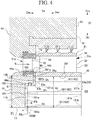
- FIG. 4 is a sectional view of a stator vane row and a rotor blade row of a speed governing stage in the steam turbine of the second embodiment of the present invention.
- a first orthogonal surface 23p, a disk intermediate peripheral surface 23q, and a disk second orthogonal surface 23r are formed on the upstream surface 23u toward the upstream side Dau.
- the disk first orthogonal surface 23p extends to be orthogonal to the axial direction Da from the end surface 35u of the platform 35 on the upstream side Dau toward the radially inner side Dri.
- the disk intermediate peripheral surface 23q extends from the disk first orthogonal surface 23p toward the upstream side Dau along the axial direction Da and is toward the radially outer side Dro.
- the disk second orthogonal surface 23r extends to be orthogonal to the axial direction Da from the upstream side Dau of the disk intermediate peripheral surface 23q toward the radially inner side Dri.
- a first orthogonal surface 46p, an intermediate peripheral surface 46q, and a second orthogonal surface 46r are formed.
- the first orthogonal surface 46p faces the end surface 35u of the platform 35 of the speed governing stage rotor blade row 31a and the disk first orthogonal surface 23p of the speed governing stage disk portion 23a.
- the intermediate peripheral surface 46q extends from the disk first orthogonal surface 46p toward the upstream side Dau along the axial direction Da and is toward the radially inner side Dri.
- the second orthogonal surface 46r extends to be orthogonal to the axial direction Da from the upstream side Dau of the intermediate peripheral surface 46q toward the radially inner side Dri.
- the end surface 35u, the disk first orthogonal surface 23p, the disk intermediate peripheral surface 23q, and the disk second orthogonal surface 23r, and the first orthogonal surface 46p, the intermediate peripheral surface 46q, and the second orthogonal surface 46r are respectively formed to be approximately parallel to each other with predetermined clearances. That is, the gap flow passage 100B is formed by the end surface 35u, the disk first orthogonal surface 23p, the disk intermediate peripheral surface 23q, and the disk second orthogonal surface 23r and the first orthogonal surface 46p, the intermediate peripheral surface 46q, and the second orthogonal surface 46r.
- a seal fin is provided on the intermediate peripheral surface 46q.
- the seal fin 60 protrudes from the intermediate peripheral surface 46q to the disk second orthogonal surface 23r toward the radially inner side Dri.
- a seal member provided on the intermediate peripheral surface 46q is not limited to the seal fin 60 and may be any member as long as it can seal a portion between the intermediate peripheral surface 46q and the disk second orthogonal surface 23r.
- a labyrinth seal may be provided between the intermediate peripheral surface 46q and the disk second orthogonal surface 23r.
- the gap flow passage 100B formed between the speed governing stage stator vane row 41a and the speed governing stage rotor blade row 31a includes an outer peripheral side flow passage portion 108, an intermediate flow passage portion 109, and an inner peripheral side flow passage portion 110.
- the outer peripheral side flow passage portion 108 is provided between the end surface 35u of the platform 35 and the disk first orthogonal surface 23p, and the first orthogonal surface 46p.
- the outer peripheral side flow passage portion 108 extends from the steam main flow passage 15 toward the radially inner side Dri.
- the intermediate flow passage portion 109 is provided between the disk intermediate peripheral surface 23q and the intermediate peripheral surface 46q.
- the intermediate flow passage portion 109 is connected to the outer peripheral side flow passage portion 108 and extends from the outer peripheral side flow passage portion 108 toward the upstream side Dau in the axial direction Da.
- the inner peripheral side flow passage portion 110 is formed between disk second orthogonal surface 23r and the second orthogonal surface 46r.
- the inner peripheral side flow passage portion 110 extends from the intermediate flow passage portion 109 to the space 17 toward the radially inner side Dri.
- the upstream end portions 101a of the gaps 101 between the rotor blades 32 and the blade grooves 28 of the speed governing stage rotor blade row 31a are connected to the gap flow passage 100B.
- the steam of the steam main flow passage chamber 12 in which steam having the higher pressure P2 than the pressure P1 of the steam inside the space 17 exists flows from the downstream end portion 101b toward the upstream end portion 101a. That is, as shown in FIG. 2 , the gap 101 which is formed between each of the blade root inner surfaces 38g of the engaging protrusion portions 38A, 38B, and 38C and each of the blade groove outer surfaces 29g of the engaging recessed portions 29A, 29B, and 29C functions as a communication passage 102.
- the steam Sh in the steam main flow passage chamber 12 having a high pressure flows to be ejected to the gap flow passage 100B through the communication passage 102. Accordingly, in the gap flow passage 100B, the flow of steam Sn which flows from the steam main flow passage 15 to the gap flow passage 100B is contracted by the high-pressure steam Sh ejected from the communication passages 102. According to the contraction flow effects, it is possible to prevent the steam Sn flowing into the gap flow passage 100B from being included in the flow.
- a portion of the steam S flowing through the steam main flow passage 15 flows into the outer peripheral side flow passage portion 108 of the gap flow passage 100B.
- the steam S which flows into the outer peripheral side flow passage portion 108 flows to the space 17 via the intermediate flow passage portion 109 and the inner peripheral side flow passage portion 110.
- the steam Sh inside the steam main flow passage chamber 12 having a higher pressure than the pressure of the steam S inside the space 17 flows into the gap flow passage 100B through the communication passages 102. Accordingly, the flow of the steam S flowing through the outer peripheral side flow passage portion 108 or the inner peripheral side flow passage portion 110 of the gap flow passage 100B is contracted.
- the gap flow passage 100B is largely bent in a crank shape from the radially outer side Dro toward the radially inner side Dri in order of the outer peripheral side flow passage portion 108, the intermediate flow passage portion 109, and the inner peripheral side flow passage portion 110. Accordingly, a flow passage resistance of the gap flow passage 100B increases, and thus, it is possible to decrease the amount of the steam S leaking out from the steam main flow passage 15.
- the seal fin 60 extending to the radially inner side Dri is provided in the intermediate flow passage portion 109 which is a portion which is bent in a crank shape. Accordingly, it is possible to increase sealability in the gap flow passage 100B.
- the present invention is not limited to the above-described embodiments and design can be changed within a scope which does not depart from the gist of the present invention.
- the gap 101 formed between the blade root inner surfaces 38g of the engaging protrusion portions 38A, 38B, and 38C of each rotor blade 32 and the blade groove outer surfaces 29g of the engaging recessed portions 29A, 29B, and 29C of the blade groove 28 is used as the communication passage 102.
- the present invention is not limited to this.
- the communication passage 102 is not limited to the portions between the blade root inner surfaces 38g of the engaging protrusion portions 38A, 38B, and 38C and the blade groove outer surfaces 29g of the engaging recessed portions 29A, 29B, and 29C of the blade groove 28, and the communication passage 102 which communicates with the upstream side Dau and the downstream side Dad of the disk portion 23 may be formed in an inner peripheral portion of the blade root 36 or between the blade grooves 28 adjacent to each other in the circumferential direction Dc in the disk portion 23.
- recessed portions formed on the blade root inner surfaces 38g of the engaging protrusion portions 38A, 38B, and 38C of each rotor blade 32 to be recessed from the blade root inner surfaces 38g toward the radially outer side Dro may be the communication passages 102.
- recessed portions formed on the blade groove outer surfaces 29g of the engaging recessed portions 29A, 29B, and 29C of the blade groove 28 to be recessed from the blade groove outer surfaces 29g toward the radially inner side Dri may be the communication passages 102.
- each portion of the steam turbine 1 can be appropriately changed.
Landscapes
- Engineering & Computer Science (AREA)
- Mechanical Engineering (AREA)
- General Engineering & Computer Science (AREA)
- Turbine Rotor Nozzle Sealing (AREA)
Description
- The present invention relates to a steam turbine which is driven by steam.
- A steam turbine includes a rotor which rotates about an axis and a casing which covers the rotor. The rotor includes a rotor shaft which extends in an axial direction about an axis and a plurality of stages of rotor blade rows which are fixed to an outer periphery of the rotor shaft and are arranged in the axial direction. The steam turbine includes a stator vane row which is fixed to an inner periphery of the casing and is disposed on an upstream side of each stage of the plurality of stages of rotor blade rows.
- A steam turbine of Patent Document 1 includes a ring-shaped protrusion which protrudes from a downstream side end surface of an inner ring provided on an inner peripheral side of a stator vane of a stator vane row toward a downstream side thereof. In addition, the steam turbine includes a ring-shaped protrusion which protrudes from an upstream side end surface of a tubular rotor blade support portion provided on an inner peripheral side of a rotor blade configuring a rotor blade row toward an upstream side thereof. In addition, in the steam turbine, the ring-shaped protrusion on the stator vane side is disposed on the outer peripheral side of the ring-shaped protrusion on the rotor blade side, and the protrusions are provided to overlap each other in an axial direction. Accordingly, a gap between the stator vanes and the rotor blades is bent in a crank shape, and thus, steam flowing through a steam main flow passage is prevented from leaking from a gap between the rotor blade rows and the stator vane rows toward the inner peripheral side.
- [Patent Document 1] Japanese Unexamined Patent Application, First Publication No.
2015-25404 - However, in order to improve efficiency of a steam turbine, it is preferable to more reliably prevent the steam flowing through the steam main flow passage from leaking.
- The present invention provides a steam turbine capable of decreasing a leakage amount of steam flowing through the steam main flow passage and improving turbine efficiency.
- According to a first aspect of the present invention, there is provided a steam turbine, including: a rotor shaft which includes a shaft core portion which rotates about an axis and a disk portion which is fixed to the shaft core portion and expands toward a radially outer side in the shaft core portion; a plurality of rotor blade rows which are fixed to an outer periphery of the disk portion and are arranged in an axial direction in which the shaft core portion extends; and a stator vane row which is adjacent to an upstream side of the rotor blade row in the axial direction for each of the plurality of rotor blade rows, in which a gap flow passage, which extends toward a radially inner side from a steam main flow passage which extends in the axial direction and through which steam flows, is formed in a gap between the stator vane row and the rotor blade row configuring a speed governing stage disposed on the most upstream side among a plurality of stages configured by combinations of the rotor blade rows and the stator vane rows disposed to be adjacent to upstream sides of the rotor blade row, and a communication passage includes a first end which communicates with the gap flow passage and a second end which communicates with a space in which steam having a higher pressure than a pressure of the steam inside the gap flow passage exists, and the communication passage is formed in the disk portion to which the rotor blade row of the speed governing stage is fixed.
- According to this configuration, steam flows into the gap flow passage through the communication passage. Accordingly, the flow of the steam which leaks out from the steam main flow passage and flows through the gap flow passage is contracted. That is, the flow of the steam in the gap flow passage is obstructed, and thus, it is possible to decrease the amount of the steam leaking from the steam main flow passage to the gap flow passage.
- According to a second aspect of the present invention, in the steam turbine of the first aspect, the steam turbine may further include a fin which is provided on the steam main flow passage side of the gap flow passage in the radial direction and extends from the rotor blade row toward the stator vane row.
- Accordingly, the fin is provided in the gap flow passage, and thus, an interval between the rotor blade row and the stator vane row of the speed governing stage is narrowed, and it is possible to further decrease an amount of steam flowing into the gap flow passage.
- In a steam turbine according to a third aspect of the present invention, in the steam turbine of the second aspect, a flow passage width of the gap flow passage may be larger than a gap between a tip portion of the fin and an end portion on a downstream side of the stator vane row and may be smaller than a gap between an end portion on an upstream side of the rotor blade row of the speed governing stage and an end portion on a downstream side of the stator vane row of the speed governing stage.
- Accordingly, it is possible to form the gap flow passage which most effectively uses contraction flow effects by steam ejected from the communication passage.
- In a steam turbine according to a third aspect of the present invention, in the steam turbine of the first to third aspects, the gap flow passage may include an outer peripheral side flow passage portion which extends from the steam main flow passage toward the radially inner side, an intermediate flow passage portion which is connected to the outer peripheral side flow passage portion and extends in the axial direction, and an inner peripheral side flow passage portion which extends from the intermediate flow passage portion toward the radially inner side.
- Accordingly, the gap flow passage is bent in a crank shape from the outer peripheral side toward the inner peripheral side, and thus, a flow passage resistance increases and it is possible to decrease the amount of the steam leaking out from the steam main flow passage.
- According to the above-described steam turbine, steam flows from the communication passage into the gap flow passage formed in the gap between the stator vane row and the rotor blade row configuring the speed governing stage. Therefore, it is possible to decrease a leakage amount of steam flowing into the steam main flow passage and it is possible to improve turbine efficiency.
-
-
FIG. 1 is a sectional view of a steam turbine according to a first embodiment of the present invention. -
FIG. 2 is a view showing an attachment structure of a rotor blade to a disk portion in the steam turbine of the first embodiment of the present invention. -
FIG. 3 is a sectional view of a stator vane row and a rotor blade row of a speed governing stage in the steam turbine of the first embodiment of the present invention. -
FIG. 4 is a sectional view of a stator vane row and a rotor blade row of a speed governing stage in a steam turbine of a second embodiment of the present invention. -
FIG. 1 is a sectional view of a steam turbine according to a first embodiment of the present invention.FIG. 2 is a view showing an attachment structure of a rotor blade to a disk portion in the steam turbine of the first embodiment of the present invention.FIG. 3 is a sectional view of a stator vane row and a rotor blade row of a speed governing stage in the steam turbine of the first embodiment of the present invention. - As shown in
FIG. 1 , a steam turbine 1 of the present embodiment includes arotor 20 which rotates about an axis Ar and acasing 10 which covers therotor 20 to be rotatable. - In addition, for convenience of the following descriptions, a direction in which the axis Ar extends is referred to an axial direction Da, a first side in the axial direction Da is referred to as an upstream side (one side, first side) Dau, and a second side in the axial direction Da is referred to as a downstream side (the other side, second side) Dad. Moreover, a radial direction in a
shaft core portion 22 described later based on the axis Ar is simply referred to a radial direction Dr, a side close to the axis Ar in the radial direction Dr is referred to as a radially inner side Dri, and a side opposite to the radially inner side Dri in the radial direction Dr is referred to as a radially outer side Dro. In addition, a circumferential direction of theshaft core portion 22 about the axis Ar is simply referred to as a circumferential direction Dc. - The
rotor 20 includes arotor shaft 21 and a plurality ofrotor blade rows 31 which are provided at intervals therebetween along the axial direction Da of therotor shaft 21. - The
rotor shaft 21 includes ashaft core portion 22 which is formed in a columnar shape about the axis Ar, and extends in the axial direction Da and a plurality ofdisk portions 23 which extend from theshaft core portion 22 toward the radially outer side Dro and are arranged at intervals therebetween in the axial direction Da. Thedisk portion 23 is provided for each of the plurality ofrotor blade rows 31. - The
rotor blade row 31 is attached to the outer periphery of thedisk portion 23 which is an outer peripheral portion of therotor shaft 21. The plurality ofrotor blade rows 31 are provided at intervals therebetween along the axial direction Da of therotor shaft 21. In the case of the present embodiment, the number of therotor blade rows 31 is seven. Accordingly, in the case of the present embodiment, as therotor blade rows 31, first to seventh stages ofrotor blade rows 31 are provided. - In addition, the steam turbine 1 includes a plurality of
stator vane rows 41 which are fixed to an inner periphery of thecasing 10 and are provided at intervals therebetween along the axial direction Da. Thestator vane row 41 is adjacent to an upstream side of therotor blade row 31 in the axial direction Da for each of the plurality ofrotor blade rows 31. In the case of the present embodiment, the number of thestator vane rows 41 is seven which is the same as the number of therotor blade rows 31. Accordingly, in the case of the present embodiment, as thestator vane rows 41, first to seventh stages ofstator vane rows 41 are provided. Each of the plurality ofstator vane rows 41 is disposed to be adjacent to the upstream side Dau with respect to therotor blade row 31. - In the
casing 10, a nozzle chamber 11 into which steam S flows from the outside, a steam main flow passage chamber 12 into which the steam S from the nozzle chamber 11 flows, and anexhaust chamber 13 to which the steam S which flows from the steam main flow passage chamber 12 is discharged are formed. Therotor blade row 31 and thestator vane row 41, which are positioned on the most upstream side Dau among the plurality ofrotor blade rows 31 andstator vane rows 41, are disposed between the nozzle chamber 11 and the steam main flow passage chamber 12. In other words, the inside of thecasing 10 is divided into the nozzle chamber 11 and the steam main flow passage chamber 12 by therotor blade row 31 and thestator vane row 41 positioned on the most upstream side Dau. In the steam main flow passage chamber 12, all thestator vane rows 41 and all therotor blade rows 31 except for therotor blade row 31 and thestator vane row 41 positioned on the most upstream side Dau among the plurality ofrotor blade rows 31 andstator vane rows 41 are disposed. - One stage 50 is formed for each combination of the
rotor blade row 31 and thestator vane row 41 disposed to be adjacent to the upstream side Dau of therotor blade row 31. In the steam turbine 1 of the present embodiment, thestator vane row 41 is provided with respect to each of sevenrotor blade rows 31, and thus, seven stages 50 are provided. That is, the steam turbine 1 of the present embodiment includes a first stage 51, a second stage 52, a third stage 53, a fourth stage 54, a fifth stage 55, a sixth stage 56, and a seventh stage 57 in this order from the upstream side Dau. - In the steam turbine 1 of the present embodiment, the first stage 51 which is positioned on the most upstream side among the plurality of stages 50 configures a speed governing stage 50a. The speed governing stage 50a regulates a flow rate of the steam S fed to the stage 50 positioned on the downstream side Dad from the speed governing stage 50a so as to adjust a rotating speed of the
rotor 20. - In the steam turbine 1 of the present embodiment, the second stage 52, the third stage 53, and the fourth stage 54 configure an intermediate pressure stage 50b. In addition, in the steam turbine 1 of the present embodiment, the fifth stage 55, the sixth stage 56, and the seventh stage 57 configure a low pressure stage 50c.
- Accordingly, hereinafter, the
stator vane row 41 of the first stage 51 configuring a portion of the speed governing stage 50a is referred to as a speed governing stagestator vane row 41a. Therotor blade row 31 of the first stage 51 configuring the other portion of the speed governing stage 50a is referred to as a speed governing stagerotor blade row 31a. - In addition, the
stator vane row 41 of the second stage 52 to thestator vane row 41 of the fourth stage 54 configuring a portion of the intermediate pressure stage 50b are referred to as intermediate pressure stagestator vane rows 41b. Therotor blade row 31 of the second stage 52 to therotor blade row 31 of the fourth stage 54 configuring the other portion of the intermediate pressure stage 50b are referred to as intermediate pressure stagerotor blade rows 31b. - In addition, the
stator vane row 41 of the fifth stage 55 to thestator vane row 41 of the seventh stage 57 configuring a portion of the low pressure stage 50c are referred to as low pressure stagestator vane rows 41c. Therotor blade row 31 of the fifth stage 55 to therotor blade row 31 of the seventh stage 57 configuring the other portion of the low pressure stage 50c are referred to as low pressure stagerotor blade rows 31c. - In addition, the
disk portion 23 of therotor shaft 21 to which the speed governing stagerotor blade row 31a is fixed is referred to as a speed governingstage disk portion 23a. Thedisk portions 23 of therotor shaft 21 to which the intermediate pressure stagerotor blade rows 31b are fixed are referred to as intermediate pressurestage disk portions 23b. Thedisk portions 23 of therotor shaft 21 to which the low pressure stagerotor blade rows 31c are fixed are referred to as low pressurestage disk portions 23c. - As shown in
FIGS. 1 and2 , eachrotor blade row 31 includes a plurality ofrotor blades 32 which are arranged in the circumferential direction Dc. Eachrotor blade 32 includes ablade body 33 which extends in the radial direction Dr, ashroud 34 which is provided on the radially outer side Dro of theblade body 33, aplatform 35 which is provided on the radially inner side Dri of theblade body 33, and a blade root 36 (refer toFIG. 2 ) which is provided on the radially inner side Dri of theplatform 35. In therotor blade 32, a portion between theshroud 34 and theplatform 35 configures a portion of the steammain flow passage 15 through which the steam S flows. The steammain flow passage 15 extends in the axial direction Da over the plurality ofrotor blade rows 31 and the plurality ofstator vane rows 41. The steammain flow passage 15 is formed in an annular shape around therotor 20. - As shown in
FIG. 3 , axial fins (fins) 35Fa and 35Fb are provided in the speed governing stagerotor blade row 31a. The axial fins (fins) 35Fa and 35Fb are provided to face an opening of agap flow passage 100A described later on the steammain flow passage 15 side in the radial direction Dr. The axial fins (fin) 35Fa and 35Fb extend from the speed governing stagerotor blade row 31a toward the speed governing stagestator vane row 41a. - The axial fins (fins) 35Fa and 35Fb of the present embodiment are provided on the upstream side Dau of the
platform 35 of therotor blade 32 in the axial direction Da. The axial fin 35Fa is formed to protrude toward the upstream side Dau from the radially outer side Dro of anend surface 35u which is toward the upstream side Dau of theplatform 35 in the axial direction Dau. The axial fin 35Fb is formed to protrude toward the upstream side Dau from the radially inner side Dri of theend surface 35u of theplatform 35. - The clearance between the
end surface 35u of theplatform 35 which is a front edge portion of therotor blade 32 of the speed governing stagerotor blade row 31a and aninner ring 46 described later which is a rear edge portion of thestator vane 42 of the speed governing stagestator vane row 41a is narrowed by the axial fins 35Fa and 35Fb. Accordingly, the axial fin 35Fa and the axial fin 35Fb prevent the steam S from leaking toward the radially inner side Dri from the steammain flow passage 15 extending in the axial direction Da toward the gap between the speed governing stagerotor blade row 31a and the speed governing stagestator vane row 41a. - As shown in
FIG. 2 , in each of the plurality ofrotor blades 32 configuring therotor blade row 31, as described later, theblade root 36 is fitted into ablade groove 28 formed on an outer peripheral portion of thedisk portion 23 in therotor shaft 21. - As shown in
FIG. 2 , in eachrotor blade row 31, theblade root 36 of eachrotor blade 32 is formed to extend from a platform innerperipheral surface 35f which is toward the radially inner side Dri of theplatform 35 toward the radially inner side Dri. Theblade root 36 includes ablade root body 37 which extends from the platform innerperipheral surface 35f toward the radially inner side Dri and an engagingprotrusion portion 38 which protrudes from theblade root body 37 toward both sides in the circumferential direction Dc. The engagingprotrusion portion 38 protrudes from theblade root body 37 at a plurality of locations spaced apart along the radial direction Dr. The engagingprotrusion portion 38 engages with an engaging recessedportion 29 described later which is formed on theblade groove 28. In this embodiment, the engagingprotrusion portion 38 is formed at three locations spaced apart along the radial direction Dr. Each of engagingprotrusion portions blade root 36 along the circumferential direction Dc in each of one side and the other side of theblade root 36 in the circumferential direction Dc. - Here, compared to the engaging
protrusion portion 38A on theplatform 35 side, the engagingprotrusion portion 38B and the engagingprotrusion portion 38C disposed on the radially inner side Dri of the engagingprotrusion portion 38A are formed such that protrusion dimensions thereof in the circumferential direction Dc gradually decrease. In addition, in theblade root body 37, afirst trunk 39A between theplatform 35 and the engagingprotrusion portion 38A, asecond trunk 39B between the engagingprotrusion portion 38A and the engagingprotrusion portion 38B, and athird trunk 39C between the engagingprotrusion portion 38B and the engagingprotrusion portion 38C are formed such that width dimensions thereof in the circumferential direction Dc gradually decrease from theplatform 35 side toward the radially inner side Dri. Accordingly, theblade root 36 is formed in a so-called Christmas tree shape. - In each engaging
protrusion portion 38, a blade rootouter surface 38f which is toward a direction including a directional component toward the radially outer side Dro is formed. The blade rootouter surface 38f is a surface which is formed on the radially outer side Dro in the engagingprotrusion portion 38. In addition, the direction of the blade rootouter surface 38f may be any direction as long as it includes a directional component toward the radially outer side Dro, may be a direction parallel to the radial direction Dr, or may be a direction inclined to the radial direction Dr. - In addition, in each engaging
protrusion portion 38, a blade rootinner surface 38g which is toward a direction including a directional component toward the radially inner side Dri is formed. The blade rootinner surface 38g is a surface which is formed on the radially inner side Dri in the engagingprotrusion portion 38. In addition, the direction of the blade rootinner surface 38g may be any direction as long as it includes a directional component toward the radially inner side Dri, may be a direction parallel to the radial direction Dr, or may be a direction inclined to the radial direction Dr. - The
blade groove 28 which extends toward the radially inner side Dri is formed on the outer peripheral portion of eachdisk portion 23. Theblade groove 28 is formed to be recessed from a rotor outerperipheral surface 23f formed on the radially outermost side Dro of thedisk portion 23 toward the radially inner side Dri. The rotor outerperipheral surface 23f faces the platform innerperipheral surface 35f. - The
blade groove 28 is formed to make up the outer peripheral shape of theblade root 36. Theblade groove 28 includes the engaging recessedportion 29 recessed toward both side in the circumferential direction Dc at a plurality of locations spaced apart along the radial direction Dr. In this embodiment, the engaging recessedportion 29 is formed at three locations spaced apart along the radial direction Dr in each of one side and the other side of theblade groove 28 in the circumferential direction Dc. Each of engaging recessedportions blade groove 28 along the circumferential direction Dc. - Each engaging recessed
portion 29 includes a blade grooveinner surface 29f which is toward a direction including a directional component toward the radially inner side Dri. The blade grooveinner surface 29f is a surface which is formed on the radially outer side Dro in the engaging recessedportion 29. In addition, the direction of the blade grooveinner surface 29f may be any direction as long as it includes a directional component toward the radially inner side Dri, may be a direction parallel to the radial direction Dr, or may be a direction inclined to the radial direction Dr. - In addition, each engaging recessed
portion 29 includes a blade grooveouter surface 29g which is toward a direction including a directional component toward the radially outer side Dro. The blade grooveouter surface 29g is a surface which is formed on the radially inner side Dri in the engaging recessedportion 29. In addition, the direction of the blade grooveouter surface 29g may be any direction as long as it includes a directional component toward the radially outer side Dro, may be a direction parallel to the radial direction Dr, or may be a direction inclined to the radial direction Dr. - Here, if the
rotor shaft 21 rotates around the axis Ar, therotor blades 32 pivot about the axis Ar of therotor shaft 21 along with thedisk portion 23 of therotor shaft 21. Accordingly, a centrifugal force is applied to therotor blades 32. Therotor blades 32 are displaced toward the radially outer side Dro by the centrifugal force. As a result, the blade rootouter surfaces 38f of the engagingprotrusion portions inner surfaces 29f of the engaging recessedportions rotor blade 32 is supported in a state where the blade rootouter surfaces 38f of theblade root 36 and the blade grooveinner surfaces 29f of theblade groove 28 come into contact with each other. - Meanwhile, the centrifugal force is generated in the
rotor blades 32, and thus, a distance between the blade rootinner surface 38g of each of the engagingprotrusion portions outer surface 29g of each of the engaging recessedportions gap 101 between each blade rootinner surface 38g and each blade grooveouter surface 29g increases. As shown inFIG. 3 , thegap 101 is formed to be continuous along the axial direction Da to communicate with the upstream side Dau and the downstream side Dad of thedisk portion 23. - As shown in
FIG. 3 , the speed governingstage disk portion 23a includes, on anupstream surface 23u toward the upstream side Dau, athick portion 23n which is set to have a thicker thickness along the axial direction Da than that of theplatform 35 to increase strength. In addition, the speed governingstage disk portion 23a includes, on the radially outer side Dro of thethick portion 23n, thethickness increasing portion 23z in which a plate thickness in the axial direction Da gradually increases from the platform innerperipheral surface 35f side of theplatform 35 toward thethick portion 23n. - Accordingly, in the speed governing
stage disk portion 23a, adisk inclination surface 23k and anorthogonal surface 23t are formed on theupstream surface 23u which is toward the upstream side Dau. Thedisk inclination surface 23k is inclined on the upstream side Dau from theend surface 35u on the upstream side Dau of theplatform 35 toward the radially inner side Dri. Theorthogonal surface 23t extends to be orthogonal to the axial direction Da from thedisk inclination surface 23k toward the radially inner side Dri. - As shown in
FIG. 1 , thestator vane row 41 includes the plurality ofstator vanes 42 which are arranged in the circumferential direction Dc, an annularouter ring 43 which is provided on the radially outer side Dro of the plurality ofstator vanes 42, and the annularinner ring 46 which is provided on the radially inner side Dri of the plurality ofstator vanes 42. That is, the plurality ofstator vanes 42 are disposed between theouter ring 43 and theinner ring 46. The stator vanes 42 are fixed to theouter ring 43 and theinner ring 46. An annular space between theouter ring 43 and theinner ring 46 configures a portion of the steammain flow passage 15 through which the steam S flows. Theouter ring 43 includes aring body portion 44 to which the plurality ofstator vanes 42 are fixed and aring protrusion portion 45 which protrudes from thering body portion 44 toward the downstream side Dad. Thering protrusion portion 45 faces theshroud 34 of therotor blade row 31, which is adjacent to the downstream side Dad of thestator vane row 41, at an interval therebetween in the radial direction Dr. - In the speed governing stage
stator vane row 41a among the plurality ofstator vane row 41, a firstorthogonal surface 41s, aninclination surface 41k, and a secondorthogonal surface 41t are formed. - The first
orthogonal surface 41s faces theend surface 35u of theplatform 35 of the speed governing stagerotor blade row 31a. Theinclination surface 41k faces thedisk inclination surface 23k of thedisk portion 23 on the radially inner side Dri of the firstorthogonal surface 41s. The secondorthogonal surface 41t faces theorthogonal surface 23t of thedisk portion 23 on the radially inner side Dri of theinclination surface 41k. - The first
orthogonal surface 41s, theinclination surface 41k, and the secondorthogonal surface 41t are formed to be approximately parallel to theend surface 35u, thedisk inclination surface 23k, and theorthogonal surface 23t with predetermined clearances along the axial direction Da. - In this way, the
gap flow passage 100A which extends from the steammain flow passage 15 to the radially inner side Dri is formed in a gap between the speed governing stagestator vane row 41a and the speed governing stagerotor blade row 31a. In this embodiment, thegap flow passage 100A includes an outer peripheral sideflow passage portion 103 which extends toward the radially inner side Dri, an inclinationflow passage portion 104 which is inclined to the upstream side Dau from the outer peripheral sideflow passage portion 103 toward the radially inner side Dri, and an inner peripheral sideflow passage portion 105 which extends from the inclinationflow passage portion 104 toward the radially inner side Dri. - The outer peripheral side
flow passage portion 103 is formed between theend surface 35u of theplatform 35 and the firstorthogonal surface 41s. The outer peripheral sideflow passage portion 103 extends from the steammain flow passage 15 to the inclinationflow passage portion 104. - The inclination
flow passage portion 104 is formed between theinclination surface 41k and thedisk inclination surface 23k. The inclinationflow passage portion 104 is formed as a flow passage which is continuous to the outer peripheral sideflow passage portion 103. - The inner peripheral side
flow passage portion 105 is formed between the secondorthogonal surface 41t and theorthogonal surface 23t. The inner peripheral sideflow passage portion 105 is formed as a flow passage which is continuous to the inclinationflow passage portion 104. - Here, preferably, the
gap flow passage 100A is formed such that a length dimension R1 in the radial direction Dr is the same as a length R2 of theblade root 36 of therotor blade 32 in the radial direction Dr or is longer than the length R2. - The inner peripheral side
flow passage portion 105 of thegap flow passage 100A is connected to aspace 17, in which a plurality ofseal members 16 such as a labyrinth seal are provided, on the radially inner side Dri of the nozzle chamber 11. Theseal members 16 are provided on the radially inner side Dri of the nozzle chamber 11. Theseal members 16 perform sealing so as to prevent steam from leaking out from a portion between theshaft core portion 22 and thecasing 10 to the outside of thecasing 10. Thespace 17 communicates with the outside of the steam turbine 1 via theseal members 16. Accordingly, a pressure P1 in thespace 17 is lower than a pressure P2 in the steam main flow passage chamber 12 and, for example, is set to approximately 1 atm. - In addition, in the
gap flow passage 100A, flow passage widths of the outer peripheral sideflow passage portion 103, the inclinationflow passage portion 104, and the inner peripheral sideflow passage portion 105 are formed to be larger than a clearance in the axial direction Da between the tip portions of the axial fins 35Fa and 35Fb and arear end 46b of theinner ring 46 which is an end portion on the downstream side of the speed governing stagestator vane row 41a. In addition, the flow passage widths are formed to be smaller than a clearance between theend surface 35u of theplatform 35 which is an end portion on the upstream side of the speed governing stagerotor blade row 31a and therear end 46b of theinner ring 46 of the speed governing stagestator vane row 41a. - An
upstream end portion 101a which is a first end in the axial direction Da of thegap 101 between eachrotor blade 32 and theblade groove 28 of the speed governing stagerotor blade row 31a is connected to thegap flow passage 100A. In thegap 101, steam of the steam main flow passage chamber 12, in which steam having the higher pressure P2 than the pressure P1 of the steam inside thespace 17 exists, flows from thedownstream end portion 101b which is a second end in the axial direction Da toward theupstream end portion 101a. That is, as shown inFIG. 2 , thegap 101 which is formed between each of the blade rootinner surfaces 38g of the engagingprotrusion portions outer surfaces 29g of the engaging recessedportions communication passage 102. Accordingly, thegap flow passage 100A communicates with the steam main flow passage chamber 12, in which steam having the higher pressure P2 than the pressure P1 of the steam inside thespace 17 exists, via thecommunication passages 102. - As shown in
FIG. 3 , in thegap flow passage 100A, a portion of steam of the steammain flow passage 15 passing through thestator vane 42 of the speed governing stagestator vane row 41a from the nozzle chamber 11 flows into thegap flow passage 100A from the gap between therear end 46b of theinner ring 46 and theend surface 35u of theplatform 35 of the speed governing stagerotor blade row 31a. - Meanwhile, steam Sh in the steam main flow passage chamber 12 having the higher pressure P2 than that of the
space 17 flows to be ejected to thegap flow passage 100A through thecommunication passage 102. Accordingly, in thegap flow passage 100A, the flow of the steam S which flows from the steammain flow passage 15 to thegap flow passage 100A is contracted by the high-pressure steam Sh ejected from thecommunication passages 102. According to the contraction flow effects, it is possible to prevent the steam S flowing into thegap flow passage 100A from being included in the flow. - As described above, according to the steam turbine 1 of the present embodiment, a portion of the steam S flowing through the steam
main flow passage 15 flows into thegap flow passage 100A. In thegap flow passage 100A, the steam Sh inside the steam main flow passage chamber 12 having a higher pressure than the pressure of the steam S inside thespace 17 flows into thegap flow passage 100A through thecommunication passages 102. Accordingly, the flow of the steam S which leaks out from the steammain flow passage 15 and flows through thegap flow passage 100A is contracted. That is, the flow of the steam S which flows from the steammain flow passage 15 to thegap flow passage 100A is obstructed, and thus, it is possible to decrease the amount of the steam S leaking from the steammain flow passage 15 to thegap flow passage 100A. Therefore, it is possible to decrease a leakage amount toward the radially inner side Dri of the steam S flowing through steammain flow passage 15, and it is possible to improve turbine efficiency. - In addition, the axial fins 35Fa and 35Fb extending from the
rotor blade row 31 side toward thestator vane row 41 side are provided in thegap flow passage 100A. Accordingly, the interval in the axial direction Da between the speed governing stagerotor blade row 31a and the speed governing stagestator vane row 41a is narrowed, and thus, it is possible to further decrease the amount of the steam S flowing into thegap flow passage 100A. Accordingly, it is possible to further decrease the leakage amount toward the radially inner side Dri of the steam S flowing through steammain flow passage 15. - In addition, the flow passage width of the
gap flow passage 100A are formed to be larger than the clearance in the axial direction Da between the tip portions of the axial fins 35Fa and 35Fb and therear end 46b of theinner ring 46 of the speed governing stagestator vane row 41a. Accordingly, agap flow passage 100A having the minimum necessary flow passage width can be formed between the speed governing stagerotor blade row 31a and the speed governing stagestator vane row 41a. Accordingly, it is possible to form thegap flow passage 100A which most effectively uses the contraction flow effects by the steam Sh ejected from thecommunication passage 102. - In addition, the flow passage width of the
gap flow passage 100A is formed to be smaller than the clearance between theend surface 35u of theplatform 35 of the speed governing stagerotor blade row 31a and therear end 46b of theinner ring 46 of the speed governing stagestator vane row 41a. Accordingly, it is possible to form thegap flow passage 100A such that the portion between the speed governing stagerotor blade row 31a and the speed governing stagestator vane row 41a is prevented from being too wide in order to prevent reduction in effects of the steam Sh ejected from thecommunication passages 102. - Therefore, the
gap flow passage 100A is formed to have the above-described flow path width, and thus, it is possible to form thegap flow passage 100A which effectively uses the contraction flow effects by the steam Sh ejected from thecommunication passage 102. - Next, a second embodiment of the steam turbine according to the present invention will be described. Compared to the steam turbine of the first embodiment, in the steam turbine shown in the second embodiment, only a
gap flow passage 100B is different. Accordingly, in descriptions of the second embodiment, the same reference numerals are assigned to the same portions of the first embodiment, and overlapping descriptions thereof are omitted. That is, all the configurations of the steam turbine common to the configurations described in the first embodiment will be omitted. -
FIG. 4 is a sectional view of a stator vane row and a rotor blade row of a speed governing stage in the steam turbine of the second embodiment of the present invention. - As shown in
FIG. 4 , in the steam turbine 1 of the second embodiment, in thedisk portion 23 of therotor blade row 31 of the speed governing stage 50a, a firstorthogonal surface 23p, a disk intermediateperipheral surface 23q, and a disk secondorthogonal surface 23r are formed on theupstream surface 23u toward the upstream side Dau. - The disk first
orthogonal surface 23p extends to be orthogonal to the axial direction Da from theend surface 35u of theplatform 35 on the upstream side Dau toward the radially inner side Dri. The disk intermediateperipheral surface 23q extends from the disk firstorthogonal surface 23p toward the upstream side Dau along the axial direction Da and is toward the radially outer side Dro. The disk secondorthogonal surface 23r extends to be orthogonal to the axial direction Da from the upstream side Dau of the disk intermediateperipheral surface 23q toward the radially inner side Dri. - In the speed governing stage
stator vane row 41a of the second embodiment, a firstorthogonal surface 46p, an intermediateperipheral surface 46q, and a secondorthogonal surface 46r are formed. - The first
orthogonal surface 46p faces theend surface 35u of theplatform 35 of the speed governing stagerotor blade row 31a and the disk firstorthogonal surface 23p of the speed governingstage disk portion 23a. - The intermediate
peripheral surface 46q extends from the disk firstorthogonal surface 46p toward the upstream side Dau along the axial direction Da and is toward the radially inner side Dri. - The second
orthogonal surface 46r extends to be orthogonal to the axial direction Da from the upstream side Dau of the intermediateperipheral surface 46q toward the radially inner side Dri. - The
end surface 35u, the disk firstorthogonal surface 23p, the disk intermediateperipheral surface 23q, and the disk secondorthogonal surface 23r, and the firstorthogonal surface 46p, the intermediateperipheral surface 46q, and the secondorthogonal surface 46r are respectively formed to be approximately parallel to each other with predetermined clearances. That is, thegap flow passage 100B is formed by theend surface 35u, the disk firstorthogonal surface 23p, the disk intermediateperipheral surface 23q, and the disk secondorthogonal surface 23r and the firstorthogonal surface 46p, the intermediateperipheral surface 46q, and the secondorthogonal surface 46r. - In addition, a seal fin is provided on the intermediate
peripheral surface 46q. The seal fin 60 protrudes from the intermediateperipheral surface 46q to the disk secondorthogonal surface 23r toward the radially inner side Dri. - In addition, a seal member provided on the intermediate
peripheral surface 46q is not limited to the seal fin 60 and may be any member as long as it can seal a portion between the intermediateperipheral surface 46q and the disk secondorthogonal surface 23r. For example, a labyrinth seal may be provided between the intermediateperipheral surface 46q and the disk secondorthogonal surface 23r. - The
gap flow passage 100B formed between the speed governing stagestator vane row 41a and the speed governing stagerotor blade row 31a includes an outer peripheral sideflow passage portion 108, an intermediateflow passage portion 109, and an inner peripheral sideflow passage portion 110. - The outer peripheral side
flow passage portion 108 is provided between theend surface 35u of theplatform 35 and the disk firstorthogonal surface 23p, and the firstorthogonal surface 46p. The outer peripheral sideflow passage portion 108 extends from the steammain flow passage 15 toward the radially inner side Dri. - The intermediate
flow passage portion 109 is provided between the disk intermediateperipheral surface 23q and the intermediateperipheral surface 46q. The intermediateflow passage portion 109 is connected to the outer peripheral sideflow passage portion 108 and extends from the outer peripheral sideflow passage portion 108 toward the upstream side Dau in the axial direction Da. - The inner peripheral side
flow passage portion 110 is formed between disk secondorthogonal surface 23r and the secondorthogonal surface 46r. The inner peripheral sideflow passage portion 110 extends from the intermediateflow passage portion 109 to thespace 17 toward the radially inner side Dri. - The
upstream end portions 101a of thegaps 101 between therotor blades 32 and theblade grooves 28 of the speed governing stagerotor blade row 31a are connected to thegap flow passage 100B. In each of thegaps 101, the steam of the steam main flow passage chamber 12, in which steam having the higher pressure P2 than the pressure P1 of the steam inside thespace 17 exists, flows from thedownstream end portion 101b toward theupstream end portion 101a. That is, as shown inFIG. 2 , thegap 101 which is formed between each of the blade rootinner surfaces 38g of the engagingprotrusion portions outer surfaces 29g of the engaging recessedportions communication passage 102. - As shown in
FIG. 4 , in thegap flow passage 100B, a portion of steam of the steammain flow passage 15 passing through the speed governing stagestator vane row 41a from the nozzle chamber 11 flows into thegap flow passage 100B from the gap between therear end 46b of theinner ring 46 and theend surface 35u of theplatform 35 of the speed governing stagerotor blade row 31a. - Meanwhile, the steam Sh in the steam main flow passage chamber 12 having a high pressure flows to be ejected to the
gap flow passage 100B through thecommunication passage 102. Accordingly, in thegap flow passage 100B, the flow of steam Sn which flows from the steammain flow passage 15 to thegap flow passage 100B is contracted by the high-pressure steam Sh ejected from thecommunication passages 102. According to the contraction flow effects, it is possible to prevent the steam Sn flowing into thegap flow passage 100B from being included in the flow. - According to the steam turbine 1 of the embodiment, a portion of the steam S flowing through the steam
main flow passage 15 flows into the outer peripheral sideflow passage portion 108 of thegap flow passage 100B. The steam S which flows into the outer peripheral sideflow passage portion 108 flows to thespace 17 via the intermediateflow passage portion 109 and the inner peripheral sideflow passage portion 110. In this case, in thegap flow passage 100B, the steam Sh inside the steam main flow passage chamber 12 having a higher pressure than the pressure of the steam S inside thespace 17 flows into thegap flow passage 100B through thecommunication passages 102. Accordingly, the flow of the steam S flowing through the outer peripheral sideflow passage portion 108 or the inner peripheral sideflow passage portion 110 of thegap flow passage 100B is contracted. That is, the flow of the steam S which flows from the steammain flow passage 15 to thegap flow passage 100B is obstructed, and thus, it is possible to decrease the amount of the steam S leaking from the steammain flow passage 15 to thegap flow passage 100B. Therefore, it is possible to decrease the leakage amount toward the radially inner side Dri of the steam S flowing through steammain flow passage 15, and it is possible to improve turbine efficiency. - In addition, the
gap flow passage 100B is largely bent in a crank shape from the radially outer side Dro toward the radially inner side Dri in order of the outer peripheral sideflow passage portion 108, the intermediateflow passage portion 109, and the inner peripheral sideflow passage portion 110. Accordingly, a flow passage resistance of thegap flow passage 100B increases, and thus, it is possible to decrease the amount of the steam S leaking out from the steammain flow passage 15. - In addition, the seal fin 60 extending to the radially inner side Dri is provided in the intermediate
flow passage portion 109 which is a portion which is bent in a crank shape. Accordingly, it is possible to increase sealability in thegap flow passage 100B. - In addition, the present invention is not limited to the above-described embodiments and design can be changed within a scope which does not depart from the gist of the present invention.
- For example, the
gap 101 formed between the blade rootinner surfaces 38g of the engagingprotrusion portions rotor blade 32 and the blade grooveouter surfaces 29g of the engaging recessedportions blade groove 28 is used as thecommunication passage 102. However, the present invention is not limited to this. - For example, the
communication passage 102 is not limited to the portions between the blade rootinner surfaces 38g of the engagingprotrusion portions outer surfaces 29g of the engaging recessedportions blade groove 28, and thecommunication passage 102 which communicates with the upstream side Dau and the downstream side Dad of thedisk portion 23 may be formed in an inner peripheral portion of theblade root 36 or between theblade grooves 28 adjacent to each other in the circumferential direction Dc in thedisk portion 23. - In addition, recessed portions formed on the blade root
inner surfaces 38g of the engagingprotrusion portions rotor blade 32 to be recessed from the blade rootinner surfaces 38g toward the radially outer side Dro may be thecommunication passages 102. Moreover, recessed portions formed on the blade grooveouter surfaces 29g of the engaging recessedportions blade groove 28 to be recessed from the blade grooveouter surfaces 29g toward the radially inner side Dri may be thecommunication passages 102. - In addition, the configuration of each portion of the steam turbine 1 can be appropriately changed.
- Steam flows from the communication passage into the gap flow passage formed in the gap between the stator vane row and the rotor blade row configuring the speed governing stage. Accordingly, it is possible to decrease a leakage amount of steam flowing into the steam main flow passage and it is possible to improve turbine efficiency.
-
- 1: steam turbine
- 10: casing
- 11: nozzle chamber
- 12: steam main flow passage chamber
- 13: exhaust chamber
- 15: steam main flow passage
- 16: seal member
- 17: space
- 20: rotor
- 21: rotor shaft
- 22: shaft core portion
- 23: disk portion
- 23f: rotor outer peripheral surface
- 23k: disk inclination surface
- 23n: thick portion
- 23p: disk first orthogonal surface
- 23q: disk intermediate peripheral surface
- 23r: disk second orthogonal surface
- 23t: orthogonal surface
- 23u: upstream surface
- 23z: thickness increasing portion
- 28: blade groove
- 29, 29A, 29B, 29C: engaging recessed portion
- 29f: blade groove inner surface
- 29g: blade groove outer surface
- 31: rotor blade row
- 32: rotor blade
- 33: blade body
- 34: shroud
- 35: platform
- 35Fa, 35Fb: axial fin (fin)
- 35f: platform inner peripheral surface
- 35u: end surface
- 36: blade root
- 38, 38A, 38B, 38C: engaging protrusion portion
- 38f: blade root outer surface
- 38g: blade root inner surface
- 39A: first trunk
- 39B: second trunk
- 39C: third trunk
- 41: stator vane row
- 41k: inclination surface
- 41s, 46p: first orthogonal surface
- 41t, 46r: second orthogonal surface
- 42: stator vane
- 43: outer ring
- 44: ring body portion
- 45: ring protrusion portion
- 46: inner ring
- 46d: downstream surface
- 46b: rear end
- 46q: intermediate peripheral surface
- 50: stage
- 50a: speed governing stage
- 50b: intermediate pressure stage
- 50c: low pressure stage
- 60: seal fin
- 100A, 100B: gap flow passage
- 101: gap
- 101a: upstream end portion
- 101b: downstream end portion
- 102: communication passage
- 103, 108: outer peripheral side flow passage portion
- 104: inclination flow passage portion
- 105, 110: inner peripheral side flow passage portion
- 109: intermediate flow passage portion
- 121, 122: recessed portion
- Ar: axis
- Da: axial direction
- Dad: downstream side
- Dau: upstream side
- Dc: circumferential direction
- Dr: radial direction
- Dri: radially inner side
- Dro: radially outer side
- PI: pressure
- P2: pressure
- R1: dimension
- S, Sh: steam
Claims (4)
- A steam turbine, comprising:a rotor shaft which includes a shaft core portion which rotates about an axis and a disk portion which is fixed to the shaft core portion and expands toward a radially outer side in the shaft core portion;a plurality of rotor blade rows which are fixed to an outer periphery of the disk portion and are arranged in an axial direction in which the shaft core portion extends; anda stator vane row which is adjacent to an upstream side of the rotor blade row in the axial direction for each of the plurality of rotor blade rows,wherein a gap flow passage, which extends toward a radially inner side from a steam main flow passage which extends in the axial direction and through which steam flows, is formed in a gap between the stator vane row and the rotor blade row configuring a speed governing stage disposed on the most upstream side among a plurality of stages configured by combinations of the rotor blade rows and the stator vane rows disposed to be adjacent to upstream sides of the rotor blade row, andwherein a communication passage includes a first end which communicates with the gap flow passage and a second end which communicates with a space in which steam having a higher pressure than a pressure of the steam inside the gap flow passage exists, and the communication passage is formed in the disk portion to which the rotor blade row of the speed governing stage is fixed.
- The steam turbine according to claim 1, further comprising:a fin which is provided on the steam main flow passage side of the gap flow passage in the radial direction and extends from the rotor blade row toward the stator vane row.
- The steam turbine according to claim 2,
wherein a flow passage width of the gap flow passage is larger than a gap between a tip portion of the fin and an end portion on a downstream side of the stator vane row and is smaller than a gap between an end portion on an upstream side of the rotor blade row of the speed governing stage and an end portion on a downstream side of the stator vane row of the speed governing stage. - The steam turbine according to any one of claims 1 to 3,
wherein the gap flow passage includes an outer peripheral side flow passage portion which extends from the steam main flow passage toward the radially inner side, an intermediate flow passage portion which is connected to the outer peripheral side flow passage portion and extends in the axial direction, and an inner peripheral side flow passage portion which extends from the intermediate flow passage portion toward the radially inner side.
Applications Claiming Priority (1)
| Application Number | Priority Date | Filing Date | Title |
|---|---|---|---|
| PCT/JP2015/073513 WO2017033227A1 (en) | 2015-08-21 | 2015-08-21 | Steam turbine |
Publications (3)
| Publication Number | Publication Date |
|---|---|
| EP3284915A1 true EP3284915A1 (en) | 2018-02-21 |
| EP3284915A4 EP3284915A4 (en) | 2018-04-25 |
| EP3284915B1 EP3284915B1 (en) | 2019-06-19 |
Family
ID=58100156
Family Applications (1)
| Application Number | Title | Priority Date | Filing Date |
|---|---|---|---|
| EP15902199.7A Active EP3284915B1 (en) | 2015-08-21 | 2015-08-21 | Steam turbine |
Country Status (4)
| Country | Link |
|---|---|
| US (1) | US10513937B2 (en) |
| EP (1) | EP3284915B1 (en) |
| JP (1) | JP6507460B2 (en) |
| WO (1) | WO2017033227A1 (en) |
Families Citing this family (4)
| Publication number | Priority date | Publication date | Assignee | Title |
|---|---|---|---|---|
| USD941360S1 (en) * | 2019-01-31 | 2022-01-18 | Elliott Company | Oval steam turbine casing |
| JP7356285B2 (en) | 2019-07-31 | 2023-10-04 | 三菱重工業株式会社 | axial flow turbine |
| JP2021110291A (en) * | 2020-01-10 | 2021-08-02 | 三菱重工業株式会社 | Rotor blade and axial flow rotary machine |
| KR20230088458A (en) * | 2021-06-28 | 2023-06-19 | 미츠비시 파워 가부시키가이샤 | Turbine stators, and steam turbines |
Family Cites Families (22)
| Publication number | Priority date | Publication date | Assignee | Title |
|---|---|---|---|---|
| JPS5257410A (en) * | 1975-11-07 | 1977-05-11 | Hitachi Ltd | Leakage sealing mechanism for axial fluid machine |
| JPS55177006U (en) * | 1979-06-06 | 1980-12-19 | ||
| DE3006286A1 (en) * | 1980-02-01 | 1981-08-06 | BBC AG Brown, Boveri & Cie., Baden, Aargau | PRESSURIZED STEAM TURBINE WITH A COMPARISON LEVEL |
| JPS59130005U (en) * | 1983-02-21 | 1984-08-31 | 株式会社東芝 | steam turbine |
| JPS6170102A (en) * | 1984-09-12 | 1986-04-10 | Mitsubishi Heavy Ind Ltd | Nozzle chamber of steam turbine |
| JP2721730B2 (en) * | 1990-04-10 | 1998-03-04 | 三菱重工業株式会社 | Leakage steam temperature measurement method |
| FR2675536B1 (en) * | 1991-04-19 | 1994-12-09 | Alsthom Gec | TURBINE WITH ACTION WITH ROTOR DRUM AND IMPROVEMENT WITH THESE TURBINES. |
| JPH06200704A (en) * | 1992-12-28 | 1994-07-19 | Mitsubishi Heavy Ind Ltd | Steam turbine nozzle chamber |
| JPH0734807A (en) * | 1993-07-26 | 1995-02-03 | Mitsubishi Heavy Ind Ltd | Double discharge type steam turbine |
| JP2895363B2 (en) * | 1993-09-27 | 1999-05-24 | 三菱重工業株式会社 | Steam turbine rotor cooling system |
| JPH10252412A (en) * | 1997-03-12 | 1998-09-22 | Mitsubishi Heavy Ind Ltd | Gas turbine sealing device |
| JP3310909B2 (en) * | 1997-07-08 | 2002-08-05 | 三菱重工業株式会社 | Gas turbine vane sealing device |
| JP2004332616A (en) | 2003-05-07 | 2004-11-25 | Toshiba Corp | Axial turbomachine |
| US6896482B2 (en) * | 2003-09-03 | 2005-05-24 | General Electric Company | Expanding sealing strips for steam turbines |
| JP2005240727A (en) * | 2004-02-27 | 2005-09-08 | Mitsubishi Heavy Ind Ltd | Impulse axial flow turbine |
| US8047767B2 (en) * | 2005-09-28 | 2011-11-01 | General Electric Company | High pressure first stage turbine and seal assembly |
| US8888436B2 (en) * | 2011-06-23 | 2014-11-18 | General Electric Company | Systems and methods for cooling high pressure and intermediate pressure sections of a steam turbine |
| JP2013076341A (en) * | 2011-09-30 | 2013-04-25 | Mitsubishi Heavy Ind Ltd | Seal structure of steam turbine |
| JP5951534B2 (en) * | 2013-03-13 | 2016-07-13 | 株式会社東芝 | Steam turbine |
| JP2015025404A (en) | 2013-07-25 | 2015-02-05 | 株式会社東芝 | Seal structure of axial flow steam turbine |
| US9664118B2 (en) * | 2013-10-24 | 2017-05-30 | General Electric Company | Method and system for controlling compressor forward leakage |
| US9702261B2 (en) | 2013-12-06 | 2017-07-11 | General Electric Company | Steam turbine and methods of assembling the same |
-
2015
- 2015-08-21 JP JP2017536070A patent/JP6507460B2/en active Active
- 2015-08-21 WO PCT/JP2015/073513 patent/WO2017033227A1/en not_active Ceased
- 2015-08-21 EP EP15902199.7A patent/EP3284915B1/en active Active
- 2015-08-21 US US15/572,528 patent/US10513937B2/en active Active
Also Published As
| Publication number | Publication date |
|---|---|
| JPWO2017033227A1 (en) | 2018-03-08 |
| US20180156050A1 (en) | 2018-06-07 |
| EP3284915B1 (en) | 2019-06-19 |
| JP6507460B2 (en) | 2019-05-08 |
| EP3284915A4 (en) | 2018-04-25 |
| US10513937B2 (en) | 2019-12-24 |
| WO2017033227A1 (en) | 2017-03-02 |
Similar Documents
| Publication | Publication Date | Title |
|---|---|---|
| EP3755886B1 (en) | Sealing arrangement between turbine shroud segments | |
| US8939711B2 (en) | Outer rim seal assembly in a turbine engine | |
| US8092152B2 (en) | Device for cooling slots of a turbomachine rotor disk | |
| US11149549B2 (en) | Blade of steam turbine and steam turbine | |
| US9121298B2 (en) | Finned seal assembly for gas turbine engines | |
| EP3663514B1 (en) | Steam turbine blade and steam turbine | |
| EP3284915B1 (en) | Steam turbine | |
| EP3177811B1 (en) | Gas turbine engine compressor | |
| KR20090091190A (en) | Turbomachinery, especially gas turbines | |
| EP3358142B1 (en) | Turbine tip shroud leakage flow control | |
| EP2649279B1 (en) | Fluid flow machine especially gas turbine penetrated axially by a hot gas stream | |
| JP2016084813A (en) | Turbine assembly | |
| EP3293362B1 (en) | Steam turbine | |
| US20140363283A1 (en) | Shroud arrangement for a fluid flow machine | |
| US9587509B2 (en) | Assembly for a fluid flow machine | |
| EP3059455B1 (en) | Compressor and gas turbine | |
| EP2948631B1 (en) | Inner casing with impulse and reaction stages for a steam turbine engine | |
| US10655483B2 (en) | Run-up surface for the guide-vane shroud plate and the rotor-blade base plate | |
| US20200011182A1 (en) | Method for modifying a turbine | |
| US11613997B2 (en) | Steam turbine | |
| US20230323780A1 (en) | Steam turbine |
Legal Events
| Date | Code | Title | Description |
|---|---|---|---|
| STAA | Information on the status of an ep patent application or granted ep patent |
Free format text: STATUS: THE INTERNATIONAL PUBLICATION HAS BEEN MADE |
|
| PUAI | Public reference made under article 153(3) epc to a published international application that has entered the european phase |
Free format text: ORIGINAL CODE: 0009012 |
|
| STAA | Information on the status of an ep patent application or granted ep patent |
Free format text: STATUS: REQUEST FOR EXAMINATION WAS MADE |
|
| 17P | Request for examination filed |
Effective date: 20171114 |
|
| AK | Designated contracting states |
Kind code of ref document: A1 Designated state(s): AL AT BE BG CH CY CZ DE DK EE ES FI FR GB GR HR HU IE IS IT LI LT LU LV MC MK MT NL NO PL PT RO RS SE SI SK SM TR |
|
| AX | Request for extension of the european patent |
Extension state: BA ME |
|
| A4 | Supplementary search report drawn up and despatched |
Effective date: 20180326 |
|
| RIC1 | Information provided on ipc code assigned before grant |
Ipc: F01D 11/10 20060101ALI20180320BHEP Ipc: F01D 11/04 20060101AFI20180320BHEP Ipc: F01D 25/00 20060101ALI20180320BHEP |
|
| GRAP | Despatch of communication of intention to grant a patent |
Free format text: ORIGINAL CODE: EPIDOSNIGR1 |
|
| STAA | Information on the status of an ep patent application or granted ep patent |
Free format text: STATUS: GRANT OF PATENT IS INTENDED |
|
| DAV | Request for validation of the european patent (deleted) | ||
| DAX | Request for extension of the european patent (deleted) | ||
| INTG | Intention to grant announced |
Effective date: 20181127 |
|
| GRAS | Grant fee paid |
Free format text: ORIGINAL CODE: EPIDOSNIGR3 |
|
| GRAJ | Information related to disapproval of communication of intention to grant by the applicant or resumption of examination proceedings by the epo deleted |
Free format text: ORIGINAL CODE: EPIDOSDIGR1 |
|
| GRAL | Information related to payment of fee for publishing/printing deleted |
Free format text: ORIGINAL CODE: EPIDOSDIGR3 |
|
| STAA | Information on the status of an ep patent application or granted ep patent |
Free format text: STATUS: REQUEST FOR EXAMINATION WAS MADE |
|
| INTC | Intention to grant announced (deleted) | ||
| GRAR | Information related to intention to grant a patent recorded |
Free format text: ORIGINAL CODE: EPIDOSNIGR71 |
|
| STAA | Information on the status of an ep patent application or granted ep patent |
Free format text: STATUS: GRANT OF PATENT IS INTENDED |
|
| GRAA | (expected) grant |
Free format text: ORIGINAL CODE: 0009210 |
|
| STAA | Information on the status of an ep patent application or granted ep patent |
Free format text: STATUS: THE PATENT HAS BEEN GRANTED |
|
| INTG | Intention to grant announced |
Effective date: 20190509 |
|
| AK | Designated contracting states |
Kind code of ref document: B1 Designated state(s): AL AT BE BG CH CY CZ DE DK EE ES FI FR GB GR HR HU IE IS IT LI LT LU LV MC MK MT NL NO PL PT RO RS SE SI SK SM TR |
|
| REG | Reference to a national code |
Ref country code: GB Ref legal event code: FG4D |
|
| REG | Reference to a national code |
Ref country code: CH Ref legal event code: EP |
|
| REG | Reference to a national code |
Ref country code: IE Ref legal event code: FG4D |
|
| REG | Reference to a national code |
Ref country code: DE Ref legal event code: R096 Ref document number: 602015032535 Country of ref document: DE |
|
| REG | Reference to a national code |
Ref country code: AT Ref legal event code: REF Ref document number: 1145770 Country of ref document: AT Kind code of ref document: T Effective date: 20190715 |
|
| REG | Reference to a national code |
Ref country code: NL Ref legal event code: MP Effective date: 20190619 |
|
| PG25 | Lapsed in a contracting state [announced via postgrant information from national office to epo] |
Ref country code: HR Free format text: LAPSE BECAUSE OF FAILURE TO SUBMIT A TRANSLATION OF THE DESCRIPTION OR TO PAY THE FEE WITHIN THE PRESCRIBED TIME-LIMIT Effective date: 20190619 Ref country code: LT Free format text: LAPSE BECAUSE OF FAILURE TO SUBMIT A TRANSLATION OF THE DESCRIPTION OR TO PAY THE FEE WITHIN THE PRESCRIBED TIME-LIMIT Effective date: 20190619 Ref country code: AL Free format text: LAPSE BECAUSE OF FAILURE TO SUBMIT A TRANSLATION OF THE DESCRIPTION OR TO PAY THE FEE WITHIN THE PRESCRIBED TIME-LIMIT Effective date: 20190619 Ref country code: FI Free format text: LAPSE BECAUSE OF FAILURE TO SUBMIT A TRANSLATION OF THE DESCRIPTION OR TO PAY THE FEE WITHIN THE PRESCRIBED TIME-LIMIT Effective date: 20190619 Ref country code: SE Free format text: LAPSE BECAUSE OF FAILURE TO SUBMIT A TRANSLATION OF THE DESCRIPTION OR TO PAY THE FEE WITHIN THE PRESCRIBED TIME-LIMIT Effective date: 20190619 Ref country code: NO Free format text: LAPSE BECAUSE OF FAILURE TO SUBMIT A TRANSLATION OF THE DESCRIPTION OR TO PAY THE FEE WITHIN THE PRESCRIBED TIME-LIMIT Effective date: 20190919 |
|
| REG | Reference to a national code |
Ref country code: LT Ref legal event code: MG4D |
|
| PG25 | Lapsed in a contracting state [announced via postgrant information from national office to epo] |
Ref country code: LV Free format text: LAPSE BECAUSE OF FAILURE TO SUBMIT A TRANSLATION OF THE DESCRIPTION OR TO PAY THE FEE WITHIN THE PRESCRIBED TIME-LIMIT Effective date: 20190619 Ref country code: RS Free format text: LAPSE BECAUSE OF FAILURE TO SUBMIT A TRANSLATION OF THE DESCRIPTION OR TO PAY THE FEE WITHIN THE PRESCRIBED TIME-LIMIT Effective date: 20190619 Ref country code: GR Free format text: LAPSE BECAUSE OF FAILURE TO SUBMIT A TRANSLATION OF THE DESCRIPTION OR TO PAY THE FEE WITHIN THE PRESCRIBED TIME-LIMIT Effective date: 20190920 Ref country code: BG Free format text: LAPSE BECAUSE OF FAILURE TO SUBMIT A TRANSLATION OF THE DESCRIPTION OR TO PAY THE FEE WITHIN THE PRESCRIBED TIME-LIMIT Effective date: 20190919 |
|
| REG | Reference to a national code |
Ref country code: AT Ref legal event code: MK05 Ref document number: 1145770 Country of ref document: AT Kind code of ref document: T Effective date: 20190619 |
|
| PG25 | Lapsed in a contracting state [announced via postgrant information from national office to epo] |
Ref country code: EE Free format text: LAPSE BECAUSE OF FAILURE TO SUBMIT A TRANSLATION OF THE DESCRIPTION OR TO PAY THE FEE WITHIN THE PRESCRIBED TIME-LIMIT Effective date: 20190619 Ref country code: PT Free format text: LAPSE BECAUSE OF FAILURE TO SUBMIT A TRANSLATION OF THE DESCRIPTION OR TO PAY THE FEE WITHIN THE PRESCRIBED TIME-LIMIT Effective date: 20191021 Ref country code: AT Free format text: LAPSE BECAUSE OF FAILURE TO SUBMIT A TRANSLATION OF THE DESCRIPTION OR TO PAY THE FEE WITHIN THE PRESCRIBED TIME-LIMIT Effective date: 20190619 Ref country code: RO Free format text: LAPSE BECAUSE OF FAILURE TO SUBMIT A TRANSLATION OF THE DESCRIPTION OR TO PAY THE FEE WITHIN THE PRESCRIBED TIME-LIMIT Effective date: 20190619 Ref country code: NL Free format text: LAPSE BECAUSE OF FAILURE TO SUBMIT A TRANSLATION OF THE DESCRIPTION OR TO PAY THE FEE WITHIN THE PRESCRIBED TIME-LIMIT Effective date: 20190619 Ref country code: CZ Free format text: LAPSE BECAUSE OF FAILURE TO SUBMIT A TRANSLATION OF THE DESCRIPTION OR TO PAY THE FEE WITHIN THE PRESCRIBED TIME-LIMIT Effective date: 20190619 Ref country code: SK Free format text: LAPSE BECAUSE OF FAILURE TO SUBMIT A TRANSLATION OF THE DESCRIPTION OR TO PAY THE FEE WITHIN THE PRESCRIBED TIME-LIMIT Effective date: 20190619 |
|
| PG25 | Lapsed in a contracting state [announced via postgrant information from national office to epo] |
Ref country code: IS Free format text: LAPSE BECAUSE OF FAILURE TO SUBMIT A TRANSLATION OF THE DESCRIPTION OR TO PAY THE FEE WITHIN THE PRESCRIBED TIME-LIMIT Effective date: 20191019 Ref country code: SM Free format text: LAPSE BECAUSE OF FAILURE TO SUBMIT A TRANSLATION OF THE DESCRIPTION OR TO PAY THE FEE WITHIN THE PRESCRIBED TIME-LIMIT Effective date: 20190619 Ref country code: ES Free format text: LAPSE BECAUSE OF FAILURE TO SUBMIT A TRANSLATION OF THE DESCRIPTION OR TO PAY THE FEE WITHIN THE PRESCRIBED TIME-LIMIT Effective date: 20190619 |
|
| PG25 | Lapsed in a contracting state [announced via postgrant information from national office to epo] |
Ref country code: TR Free format text: LAPSE BECAUSE OF FAILURE TO SUBMIT A TRANSLATION OF THE DESCRIPTION OR TO PAY THE FEE WITHIN THE PRESCRIBED TIME-LIMIT Effective date: 20190619 |
|
| PG25 | Lapsed in a contracting state [announced via postgrant information from national office to epo] |
Ref country code: DK Free format text: LAPSE BECAUSE OF FAILURE TO SUBMIT A TRANSLATION OF THE DESCRIPTION OR TO PAY THE FEE WITHIN THE PRESCRIBED TIME-LIMIT Effective date: 20190619 Ref country code: PL Free format text: LAPSE BECAUSE OF FAILURE TO SUBMIT A TRANSLATION OF THE DESCRIPTION OR TO PAY THE FEE WITHIN THE PRESCRIBED TIME-LIMIT Effective date: 20190619 |
|
| PG25 | Lapsed in a contracting state [announced via postgrant information from national office to epo] |
Ref country code: IS Free format text: LAPSE BECAUSE OF FAILURE TO SUBMIT A TRANSLATION OF THE DESCRIPTION OR TO PAY THE FEE WITHIN THE PRESCRIBED TIME-LIMIT Effective date: 20200224 Ref country code: CH Free format text: LAPSE BECAUSE OF NON-PAYMENT OF DUE FEES Effective date: 20190831 Ref country code: MC Free format text: LAPSE BECAUSE OF FAILURE TO SUBMIT A TRANSLATION OF THE DESCRIPTION OR TO PAY THE FEE WITHIN THE PRESCRIBED TIME-LIMIT Effective date: 20190619 Ref country code: LI Free format text: LAPSE BECAUSE OF NON-PAYMENT OF DUE FEES Effective date: 20190831 Ref country code: LU Free format text: LAPSE BECAUSE OF NON-PAYMENT OF DUE FEES Effective date: 20190821 |
|
| REG | Reference to a national code |
Ref country code: BE Ref legal event code: MM Effective date: 20190831 |
|
| REG | Reference to a national code |
Ref country code: DE Ref legal event code: R097 Ref document number: 602015032535 Country of ref document: DE |
|
| PLBE | No opposition filed within time limit |
Free format text: ORIGINAL CODE: 0009261 |
|
| STAA | Information on the status of an ep patent application or granted ep patent |
Free format text: STATUS: NO OPPOSITION FILED WITHIN TIME LIMIT |
|
| PG2D | Information on lapse in contracting state deleted |
Ref country code: IS |
|
| PG25 | Lapsed in a contracting state [announced via postgrant information from national office to epo] |
Ref country code: FR Free format text: LAPSE BECAUSE OF NON-PAYMENT OF DUE FEES Effective date: 20190831 Ref country code: IE Free format text: LAPSE BECAUSE OF NON-PAYMENT OF DUE FEES Effective date: 20190821 |
|
| 26N | No opposition filed |
Effective date: 20200603 |
|
| PG25 | Lapsed in a contracting state [announced via postgrant information from national office to epo] |
Ref country code: BE Free format text: LAPSE BECAUSE OF NON-PAYMENT OF DUE FEES Effective date: 20190831 Ref country code: SI Free format text: LAPSE BECAUSE OF FAILURE TO SUBMIT A TRANSLATION OF THE DESCRIPTION OR TO PAY THE FEE WITHIN THE PRESCRIBED TIME-LIMIT Effective date: 20190619 |
|
| GBPC | Gb: european patent ceased through non-payment of renewal fee |
Effective date: 20190919 |
|
| PG25 | Lapsed in a contracting state [announced via postgrant information from national office to epo] |
Ref country code: GB Free format text: LAPSE BECAUSE OF NON-PAYMENT OF DUE FEES Effective date: 20190919 |
|
| PG25 | Lapsed in a contracting state [announced via postgrant information from national office to epo] |
Ref country code: CY Free format text: LAPSE BECAUSE OF FAILURE TO SUBMIT A TRANSLATION OF THE DESCRIPTION OR TO PAY THE FEE WITHIN THE PRESCRIBED TIME-LIMIT Effective date: 20190619 |
|
| PG25 | Lapsed in a contracting state [announced via postgrant information from national office to epo] |
Ref country code: HU Free format text: LAPSE BECAUSE OF FAILURE TO SUBMIT A TRANSLATION OF THE DESCRIPTION OR TO PAY THE FEE WITHIN THE PRESCRIBED TIME-LIMIT; INVALID AB INITIO Effective date: 20150821 Ref country code: MT Free format text: LAPSE BECAUSE OF FAILURE TO SUBMIT A TRANSLATION OF THE DESCRIPTION OR TO PAY THE FEE WITHIN THE PRESCRIBED TIME-LIMIT Effective date: 20190619 |
|
| PG25 | Lapsed in a contracting state [announced via postgrant information from national office to epo] |
Ref country code: MK Free format text: LAPSE BECAUSE OF FAILURE TO SUBMIT A TRANSLATION OF THE DESCRIPTION OR TO PAY THE FEE WITHIN THE PRESCRIBED TIME-LIMIT Effective date: 20190619 |
|
| PGFP | Annual fee paid to national office [announced via postgrant information from national office to epo] |
Ref country code: DE Payment date: 20250702 Year of fee payment: 11 |
|
| PGFP | Annual fee paid to national office [announced via postgrant information from national office to epo] |
Ref country code: IT Payment date: 20250722 Year of fee payment: 11 |