EP3284844A1 - System and method for low thermal shock-fast cooling of thermal barrier coating - Google Patents
System and method for low thermal shock-fast cooling of thermal barrier coating Download PDFInfo
- Publication number
- EP3284844A1 EP3284844A1 EP17154312.7A EP17154312A EP3284844A1 EP 3284844 A1 EP3284844 A1 EP 3284844A1 EP 17154312 A EP17154312 A EP 17154312A EP 3284844 A1 EP3284844 A1 EP 3284844A1
- Authority
- EP
- European Patent Office
- Prior art keywords
- chamber
- arcuate wall
- workpiece
- cool down
- infrared lamp
- Prior art date
- Legal status (The legal status is an assumption and is not a legal conclusion. Google has not performed a legal analysis and makes no representation as to the accuracy of the status listed.)
- Granted
Links
Images

Classifications
-
- C—CHEMISTRY; METALLURGY
- C23—COATING METALLIC MATERIAL; COATING MATERIAL WITH METALLIC MATERIAL; CHEMICAL SURFACE TREATMENT; DIFFUSION TREATMENT OF METALLIC MATERIAL; COATING BY VACUUM EVAPORATION, BY SPUTTERING, BY ION IMPLANTATION OR BY CHEMICAL VAPOUR DEPOSITION, IN GENERAL; INHIBITING CORROSION OF METALLIC MATERIAL OR INCRUSTATION IN GENERAL
- C23C—COATING METALLIC MATERIAL; COATING MATERIAL WITH METALLIC MATERIAL; SURFACE TREATMENT OF METALLIC MATERIAL BY DIFFUSION INTO THE SURFACE, BY CHEMICAL CONVERSION OR SUBSTITUTION; COATING BY VACUUM EVAPORATION, BY SPUTTERING, BY ION IMPLANTATION OR BY CHEMICAL VAPOUR DEPOSITION, IN GENERAL
- C23C14/00—Coating by vacuum evaporation, by sputtering or by ion implantation of the coating forming material
- C23C14/58—After-treatment
- C23C14/5806—Thermal treatment
-
- C—CHEMISTRY; METALLURGY
- C23—COATING METALLIC MATERIAL; COATING MATERIAL WITH METALLIC MATERIAL; CHEMICAL SURFACE TREATMENT; DIFFUSION TREATMENT OF METALLIC MATERIAL; COATING BY VACUUM EVAPORATION, BY SPUTTERING, BY ION IMPLANTATION OR BY CHEMICAL VAPOUR DEPOSITION, IN GENERAL; INHIBITING CORROSION OF METALLIC MATERIAL OR INCRUSTATION IN GENERAL
- C23C—COATING METALLIC MATERIAL; COATING MATERIAL WITH METALLIC MATERIAL; SURFACE TREATMENT OF METALLIC MATERIAL BY DIFFUSION INTO THE SURFACE, BY CHEMICAL CONVERSION OR SUBSTITUTION; COATING BY VACUUM EVAPORATION, BY SPUTTERING, BY ION IMPLANTATION OR BY CHEMICAL VAPOUR DEPOSITION, IN GENERAL
- C23C14/00—Coating by vacuum evaporation, by sputtering or by ion implantation of the coating forming material
- C23C14/22—Coating by vacuum evaporation, by sputtering or by ion implantation of the coating forming material characterised by the process of coating
- C23C14/24—Vacuum evaporation
- C23C14/28—Vacuum evaporation by wave energy or particle radiation
- C23C14/30—Vacuum evaporation by wave energy or particle radiation by electron bombardment
Definitions
- the present disclosure relates to a system for thermal barrier coatings (TBCs), and more particularly, to thermal control therein.
- TBCs thermal barrier coatings
- Thermal barrier coatings are multilayer materials that are typically applied to hot sections of an engine to reduce the surface temperature experienced by workpieces.
- TBCs often include (1) a substrate, which may be an engine workpiece-typically a gamma-gamma prime superalloy (2) an aluminum rich bond coat (3) thermally grown oxide (TGO) that reduce further oxidation of bond coat by blocking oxygen (4) a low thermal conductivity ceramic top coat.
- a substrate which may be an engine workpiece-typically a gamma-gamma prime superalloy
- TGO thermally grown oxide
- EB-PVD electron beam-physical vapor deposition
- a columnar top coat microstructure develops on the surface of the workpieces in near vacuum at elevated temperatures.
- EB-PVD is a form of physical vapor deposition in which an ingot of material is bombarded with an electron beam given off by a charged tungsten filament under high vacuum. The electron beam causes atoms from the ingot to transform into the gaseous phase. These atoms then condense into solid form, coating the workpiece in the vacuum chamber, and within a line of sight, with a thin layer of the material.
- a coating system can include a reflective cool down chamber with at least one arcuate wall and an infrared lamp directed at the arcuate wall.
- a further embodiment of the present disclosure may include wherein the at least one arcuate wall includes an interior surface with a high index of reflection.
- a further embodiment of the present disclosure may include wherein the at least one arcuate wall includes an interior surface with a mirror finish.
- a further embodiment of the present disclosure may include, wherein the infrared lamp is located on a movable door that permits intake of a workpiece holder.
- a further embodiment of the present disclosure may include, wherein the infrared lamp is located on a movable door that permits egress of a workpiece holder.
- a further embodiment of the present disclosure may include a diffusion lens mounted to the infrared lamp.
- a further embodiment of the present disclosure may include a diffusion chamber adjacent to the reflective cool down chamber.
- a further embodiment of the present disclosure may include, wherein the diffusion chamber is an electron beam physical vapor deposition (EB PVD).
- EB PVD electron beam physical vapor deposition
- a method of coating a workpiece according to one disclosed non-limiting embodiment of the present disclosure can include moving a workpiece holder from a deposition chamber to a reflective cool down chamber with at least one arcuate wall; and directing infrared energy from an infrared lamp at the arcuate wall to reduce a temperature gradient of a workpiece.
- a further embodiment of the present disclosure may include directing the infrared energy for 3-10 seconds.
- a further embodiment of the present disclosure may include diffusing the infrared energy.
- a further embodiment of the present disclosure may include locating the infrared lamp on a door of the reflective cool down chamber.
- a further embodiment of the present disclosure may include, wherein the diffusion chamber is an electron beam physical vapor deposition (EB PVD).
- EB PVD electron beam physical vapor deposition
- a further embodiment of the present disclosure may include operating the infrared energy for a time in response to a thermal mass of the workpiece.
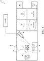
- Figure 1 schematically illustrates an example system 20 for depositing coating on workpieces 22 in the interior 24 of a deposition chamber 26.
- the system 20 passes the workpiece 22 downstream along a workpiece flowpath sequentially through a first load lock chamber 28 forming an in-feed chamber, a preheat chamber 30, the deposition chamber 26, a cool down chamber 34, and a second load lock chamber 36.
- Each of a multiple of workpieces 22 may be conveyed through the system on a workpiece holder 40 which, depending upon implementation, may support a single workpiece or multiple workpieces.
- the workpiece holder 40 may be manipulated by a sting mechanism 42.
- a loading station 50 and an unloading station 52 are provided. These may include robots (e.g., six-axis industrial robots) to transfer fixture workpieces from and to conveyors, pallets, and the like.
- the sting mechanism 42 is withdrawn back through the preheat chamber 30 into the first load lock chamber 28, such that the workpieces may be removed from the deposition chamber 26.
- the exemplary deposition chamber 26 is configured for electron beam physical vapor deposition (EB-PVD).
- EB electron beam physical vapor deposition
- at least one electron beam (EB) gun 60 is positioned to direct its beam to one or more deposition material ingots 70, 72.
- the ingots may be ceramics of different composition for forming distinct layers in a thermal barrier coating, erosion coating, abradable coating, or abrasive coating.
- Zirconia-based ingot examples include, but are not limited to, an yttria-stabilized zirconia (YSZ) such as 7YSZ, a gadolinia-stabilized zirconia, or an YSZ of different yttria content or dopant.
- YSZ yttria-stabilized zirconia
- 7YSZ a gadolinia-stabilized zirconia
- YSZ yttria-stabilized zirconia
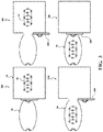
- the reflective cool down chamber 34 provides a reflective chamber that includes an arcuate wall 100 and one or more infrared lamps 102 that have diffusing lenses 104 such that the reflective cool down chamber 34 forms an ovid-like shape.
- the infrared lamps 102 may, for example, be located on a movable door 108 that permits entry and/or egress of the workpiece holder 40. The exact size and shape may be optimized such that the workpieces are cooled down slowly and uniformly.
- An interior surface 106 of the arcuate wall 100 provides a high index of reflection, e.g., mirror polish aluminum, stainless steel, etc.
- the cooling workpiece dissipates heat primarily through radiation and the reflective arcuate wall 100 of the reflective cool down chamber 34 reflects radiation back to the workpieces, thereby reducing the cooling rate.
- the infrared lamps 102 may be located on movable doors 108 that permit intake and egress of the workpiece holder 40.
- the infrared lamps 102 increase heat to make up for heat loss to the interior surface 106 of the arcuate wall 100 and also reduce the cooling rate.
- the orientation of the infrared lamps 102 is configured to uniformly distribute heat to the workpieces. Thus, temperature gradients in the workpiece are significantly reduced.
- the diffusing lenses 104 facilitate diffusion of the radiation in a suitably wide cone to permit uniform heating.
- the reflective cool down chamber 34 and infrared lamps 102 may be used in conjunction with various existing coaters.
- the infrared lamps 102 can be turned on and off quickly, unlike a heating oven that requires a relatively long time to heat up and cool down.
- the reflective cool down chamber 34 is adjacent to the deposition chamber 26 such that after the coating process is complete (step 206), the door 108 opens (step 202) such that the workpieces, which are supported by workpiece holder 40, are moved from the deposition chamber 26 to the reflective cool down chamber 34 (step 204).
- the movable doors 108 are then closed and the infrared lamps 102 are activated (step 206).
- the infrared lamps 102 may be activated for about 3-10 seconds such that the infrared energy is provided in response to a thermal mass of the workpiece.
- the workpieces are then cooled within the reflective cool down chamber 34 at a suitable rate, to prevent spallation.
Landscapes
- Chemical & Material Sciences (AREA)
- Chemical Kinetics & Catalysis (AREA)
- Engineering & Computer Science (AREA)
- Materials Engineering (AREA)
- Mechanical Engineering (AREA)
- Metallurgy (AREA)
- Organic Chemistry (AREA)
- Physics & Mathematics (AREA)
- Thermal Sciences (AREA)
- Health & Medical Sciences (AREA)
- Toxicology (AREA)
- Physical Vapour Deposition (AREA)
Abstract
Description
- The present disclosure relates to a system for thermal barrier coatings (TBCs), and more particularly, to thermal control therein.
- Thermal barrier coatings (TBCs) are multilayer materials that are typically applied to hot sections of an engine to reduce the surface temperature experienced by workpieces. TBCs often include (1) a substrate, which may be an engine workpiece-typically a gamma-gamma prime superalloy (2) an aluminum rich bond coat (3) thermally grown oxide (TGO) that reduce further oxidation of bond coat by blocking oxygen (4) a low thermal conductivity ceramic top coat.
- One of the fabrication methods for top coat is electron beam-physical vapor deposition (EB-PVD) in which a columnar top coat microstructure develops on the surface of the workpieces in near vacuum at elevated temperatures. EB-PVD is a form of physical vapor deposition in which an ingot of material is bombarded with an electron beam given off by a charged tungsten filament under high vacuum. The electron beam causes atoms from the ingot to transform into the gaseous phase. These atoms then condense into solid form, coating the workpiece in the vacuum chamber, and within a line of sight, with a thin layer of the material.
- To reduce the thermal shock between the ceramic top coat and the metallic bond coat post top coating, workpieces are slowly cooled down to room temperature in a preheated oven. The aforementioned method of cool down may be time consuming and not cost effective.
- A coating system according to one disclosed non-limiting embodiment of the present disclosure can include a reflective cool down chamber with at least one arcuate wall and an infrared lamp directed at the arcuate wall.
- A further embodiment of the present disclosure may include wherein the at least one arcuate wall includes an interior surface with a high index of reflection.
- A further embodiment of the present disclosure may include wherein the at least one arcuate wall includes an interior surface with a mirror finish.
- A further embodiment of the present disclosure may include, wherein the infrared lamp is located on a movable door that permits intake of a workpiece holder.
- A further embodiment of the present disclosure may include, wherein the infrared lamp is located on a movable door that permits egress of a workpiece holder.
- A further embodiment of the present disclosure may include a diffusion lens mounted to the infrared lamp.
- A further embodiment of the present disclosure may include a diffusion chamber adjacent to the reflective cool down chamber.
- A further embodiment of the present disclosure may include, wherein the diffusion chamber is an electron beam physical vapor deposition (EB PVD).
- A method of coating a workpiece according to one disclosed non-limiting embodiment of the present disclosure can include moving a workpiece holder from a deposition chamber to a reflective cool down chamber with at least one arcuate wall; and directing infrared energy from an infrared lamp at the arcuate wall to reduce a temperature gradient of a workpiece.
- A further embodiment of the present disclosure may include directing the infrared energy for 3-10 seconds.
- A further embodiment of the present disclosure may include diffusing the infrared energy.
- A further embodiment of the present disclosure may include locating the infrared lamp on a door of the reflective cool down chamber.
- A further embodiment of the present disclosure may include, wherein the diffusion chamber is an electron beam physical vapor deposition (EB PVD).
- A further embodiment of the present disclosure may include operating the infrared energy for a time in response to a thermal mass of the workpiece.
- The foregoing features and elements may be combined in various combinations without exclusivity, unless expressly indicated otherwise. These features and elements as well as the operation thereof will become more apparent in light of the following description and the accompanying drawings. It should be understood, however, the following description and drawings are intended to be exemplary in nature and non-limiting.
- Various features will become apparent to those skilled in the art from the following detailed description of the disclosed non-limiting embodiment. The drawings that accompany the detailed description can be briefly described as follows:
-
Figure 1 is a partial schematic view of a deposition system; and -
Figure 2 is a schematic view a reflective cool down chamber. -
Figure 3 is a schematic view of the reflective cool down chamber operation. -
Figure 1 schematically illustrates anexample system 20 for depositing coating onworkpieces 22 in theinterior 24 of adeposition chamber 26. Thesystem 20 passes theworkpiece 22 downstream along a workpiece flowpath sequentially through a firstload lock chamber 28 forming an in-feed chamber, apreheat chamber 30, thedeposition chamber 26, a cool downchamber 34, and a secondload lock chamber 36. - Each of a multiple of
workpieces 22 may be conveyed through the system on aworkpiece holder 40 which, depending upon implementation, may support a single workpiece or multiple workpieces. In thedeposition chamber 26, theworkpiece holder 40 may be manipulated by asting mechanism 42. In one embodiment, aloading station 50 and anunloading station 52 are provided. These may include robots (e.g., six-axis industrial robots) to transfer fixture workpieces from and to conveyors, pallets, and the like. - After deposition is complete, the
sting mechanism 42 is withdrawn back through thepreheat chamber 30 into the firstload lock chamber 28, such that the workpieces may be removed from thedeposition chamber 26. - The
exemplary deposition chamber 26 is configured for electron beam physical vapor deposition (EB-PVD). In this example, at least one electron beam (EB)gun 60 is positioned to direct its beam to one or moredeposition material ingots ingots - With reference to
Figure 2 , in one exemplary implementation, the reflective cool downchamber 34 provides a reflective chamber that includes anarcuate wall 100 and one or moreinfrared lamps 102 that have diffusinglenses 104 such that the reflective cool downchamber 34 forms an ovid-like shape. Theinfrared lamps 102 may, for example, be located on amovable door 108 that permits entry and/or egress of theworkpiece holder 40. The exact size and shape may be optimized such that the workpieces are cooled down slowly and uniformly. Aninterior surface 106 of thearcuate wall 100 provides a high index of reflection, e.g., mirror polish aluminum, stainless steel, etc. The cooling workpiece dissipates heat primarily through radiation and the reflectivearcuate wall 100 of the reflective cool downchamber 34 reflects radiation back to the workpieces, thereby reducing the cooling rate. - The
infrared lamps 102 may be located onmovable doors 108 that permit intake and egress of theworkpiece holder 40. Theinfrared lamps 102 increase heat to make up for heat loss to theinterior surface 106 of thearcuate wall 100 and also reduce the cooling rate. The orientation of theinfrared lamps 102 is configured to uniformly distribute heat to the workpieces. Thus, temperature gradients in the workpiece are significantly reduced. - The diffusing
lenses 104 facilitate diffusion of the radiation in a suitably wide cone to permit uniform heating. The reflective cool downchamber 34 andinfrared lamps 102 may be used in conjunction with various existing coaters. Theinfrared lamps 102 can be turned on and off quickly, unlike a heating oven that requires a relatively long time to heat up and cool down. - With reference to
Figure 3 , the reflective cool downchamber 34 is adjacent to thedeposition chamber 26 such that after the coating process is complete (step 206), thedoor 108 opens (step 202) such that the workpieces, which are supported byworkpiece holder 40, are moved from thedeposition chamber 26 to the reflective cool down chamber 34 (step 204). Themovable doors 108 are then closed and theinfrared lamps 102 are activated (step 206). In one example, theinfrared lamps 102 may be activated for about 3-10 seconds such that the infrared energy is provided in response to a thermal mass of the workpiece. The workpieces are then cooled within the reflective cool downchamber 34 at a suitable rate, to prevent spallation. - The use of the terms "a," "an," "the," and similar references in the context of description (especially in the context of the following claims) are to be construed to cover both the singular and the plural, unless otherwise indicated herein or specifically contradicted by context. The modifier "about" used in connection with a quantity is inclusive of the stated value and has the meaning dictated by the context (e.g., it includes the degree of error associated with measurement of the particular quantity). All ranges disclosed herein are inclusive of the endpoints, and the endpoints are independently combinable with each other.
- Although the different non-limiting embodiments have specific illustrated components, the embodiments of this invention are not limited to those particular combinations. It is possible to use some of the components or features from any of the non-limiting embodiments in combination with features or components from any of the other non-limiting embodiments.
- It should be appreciated that like reference numerals identify corresponding or similar elements throughout the several drawings. It should also be appreciated that although a workpiece component arrangement is disclosed in the illustrated embodiment, other arrangements will benefit herefrom.
- Although particular step sequences are shown, described, and claimed, it should be understood that steps may be performed in any order, separated or combined unless otherwise indicated and will still benefit from the present disclosure.
- The foregoing description is exemplary rather than defined by the limitations within. Various non-limiting embodiments are disclosed herein, however, one of ordinary skill in the art would recognize that various modifications and variations in light of the above teachings will fall within the scope of the appended claims. It is therefore to be understood that within the scope of the appended claims, the disclosure may be practiced other than as specifically described. For that reason the appended claims should be studied to determine true scope and content.
Claims (13)
- A coating system, comprising:a reflective cool down chamber (34) with at least one arcuate wall (100); and an infrared lamp (102) directed at the arcuate wall.
- The system as claimed in claim 1, wherein the at least one arcuate wall (100) includes an interior surface (106) with a high index of reflection.
- The system as claimed in claim 1 or 2, wherein the at least one arcuate wall (100) includes an interior surface (106) with a mirror finish.
- The system as claimed in claim 1, 2 or 3, wherein the infrared lamp (102) is located on a movable door (108) that permits intake of a workpiece holder (40).
- The system as claimed in any preceding claim, wherein the infrared lamp (102) is located on a movable door (108) that permits egress of a workpiece holder (40).
- The system as claimed in any preceding claim, further comprising a diffusion lens (104) mounted to the infrared lamp (102).
- The system as claimed in any preceding claim, further comprising a diffusion chamber adjacent to the reflective cool down chamber (34).
- A method of coating a workpiece, comprising:moving a workpiece holder (40) from a deposition chamber (26) to a reflective cool down chamber (34) with at least one arcuate wall (100); anddirecting infrared energy from an infrared lamp (102) at the arcuate wall to reduce a temperature gradient of a workpiece.
- The method as claimed in claim 8, further comprising directing the infrared energy for 3-10 seconds.
- The method as claimed in claim 8 or 9, further comprising diffusing the infrared energy.
- The method as claimed in claim 8, 9 or 10, further comprising locating the infrared lamp (102) on a door (108) of the reflective cool down chamber (34).
- The method as claimed in any of claims 8 to 11, wherein the deposition chamber (26) is an electron beam physical vapor deposition (EB-PVD).
- The method as claimed in any of claims 8 to 12, further comprising operating the infrared energy for a time in response to a thermal mass of the workpiece.
Applications Claiming Priority (1)
| Application Number | Priority Date | Filing Date | Title |
|---|---|---|---|
| US15/014,232 US20170218505A1 (en) | 2016-02-03 | 2016-02-03 | System and Method for Low Thermal Shock-Fast Cooling of Thermal Barrier Coating |
Publications (2)
| Publication Number | Publication Date |
|---|---|
| EP3284844A1 true EP3284844A1 (en) | 2018-02-21 |
| EP3284844B1 EP3284844B1 (en) | 2020-04-01 |
Family
ID=58192050
Family Applications (1)
| Application Number | Title | Priority Date | Filing Date |
|---|---|---|---|
| EP17154312.7A Active EP3284844B1 (en) | 2016-02-03 | 2017-02-02 | System and method for low thermal shock-fast cooling of thermal barrier coating |
Country Status (2)
| Country | Link |
|---|---|
| US (2) | US20170218505A1 (en) |
| EP (1) | EP3284844B1 (en) |
Citations (4)
| Publication number | Priority date | Publication date | Assignee | Title |
|---|---|---|---|---|
| DE19908387A1 (en) * | 1998-03-02 | 1999-09-09 | Behr Labortechnik | Heating samples in an analytical oven with focussed radiation |
| US20010015746A1 (en) * | 2000-02-17 | 2001-08-23 | Hisasi Yosimura | Ink drier and ink jet type image forming apparatus mounting the same |
| EP1791989A1 (en) * | 2004-08-26 | 2007-06-06 | Honeywell International Inc. | Chromium and active elements modified platinum aluminide coatings |
| CN202238582U (en) * | 2011-11-23 | 2012-05-30 | 深圳市雷巴环保材料有限公司 | Infrared drier |
Family Cites Families (13)
| Publication number | Priority date | Publication date | Assignee | Title |
|---|---|---|---|---|
| SE439129B (en) * | 1983-10-05 | 1985-06-03 | Lennart Wictorin | SET AND DEVICE FOR ASTADMATIC POINT HEATING OF A BODY, PARTICULAR TO CARRY OUT THE STAR OF GOLD MOLDING |
| JPH06102826B2 (en) | 1985-11-08 | 1994-12-14 | 松下電器産業株式会社 | Thin film manufacturing equipment |
| US5099586A (en) * | 1989-09-08 | 1992-03-31 | W. R. Grace & Co.-Conn. | Reflector assembly for heating a substrate |
| DE19537092C1 (en) * | 1995-10-05 | 1996-07-11 | Ardenne Anlagentech Gmbh | Multi-chamber electron beam vapour deposition unit |
| US5897921A (en) | 1997-01-24 | 1999-04-27 | General Electric Company | Directionally solidified thermal barrier coating |
| US6946034B1 (en) | 1999-08-04 | 2005-09-20 | General Electric Company | Electron beam physical vapor deposition apparatus |
| UA71572C2 (en) | 1999-08-04 | 2004-12-15 | Дженерал Електрік Компані | An electron beam physical vapor deposition apparatus for application of coating on articles |
| US6770333B2 (en) | 2002-04-30 | 2004-08-03 | General Electric Company | Method of controlling temperature during coating deposition by EBPVD |
| US7196460B2 (en) * | 2004-07-01 | 2007-03-27 | Osram Sylvania Inc. | Incandescent reflector heat lamp with uniform irradiance |
| CA2582312C (en) * | 2006-05-05 | 2014-05-13 | Sulzer Metco Ag | A method for the manufacture of a coating |
| US8350180B2 (en) | 2010-03-12 | 2013-01-08 | United Technologies Corporation | High pressure pre-oxidation for deposition of thermal barrier coating with hood |
| US8328945B2 (en) | 2010-03-12 | 2012-12-11 | United Technologies Corporation | Coating apparatus and method with indirect thermal stabilization |
| US9187815B2 (en) | 2010-03-12 | 2015-11-17 | United Technologies Corporation | Thermal stabilization of coating material vapor stream |
-
2016
- 2016-02-03 US US15/014,232 patent/US20170218505A1/en not_active Abandoned
-
2017
- 2017-02-02 EP EP17154312.7A patent/EP3284844B1/en active Active
-
2020
- 2020-05-27 US US16/884,602 patent/US10995402B2/en active Active
Patent Citations (4)
| Publication number | Priority date | Publication date | Assignee | Title |
|---|---|---|---|---|
| DE19908387A1 (en) * | 1998-03-02 | 1999-09-09 | Behr Labortechnik | Heating samples in an analytical oven with focussed radiation |
| US20010015746A1 (en) * | 2000-02-17 | 2001-08-23 | Hisasi Yosimura | Ink drier and ink jet type image forming apparatus mounting the same |
| EP1791989A1 (en) * | 2004-08-26 | 2007-06-06 | Honeywell International Inc. | Chromium and active elements modified platinum aluminide coatings |
| CN202238582U (en) * | 2011-11-23 | 2012-05-30 | 深圳市雷巴环保材料有限公司 | Infrared drier |
Also Published As
| Publication number | Publication date |
|---|---|
| US20170218505A1 (en) | 2017-08-03 |
| EP3284844B1 (en) | 2020-04-01 |
| US20200318231A1 (en) | 2020-10-08 |
| US10995402B2 (en) | 2021-05-04 |
Similar Documents
| Publication | Publication Date | Title |
|---|---|---|
| Feuerstein et al. | Technical and economical aspects of current thermal barrier coating systems for gas turbine engines by thermal spray and EBPVD: a review | |
| Sohn et al. | Microstructural development in physical vapour-deposited partially stabilized zirconia thermal barrier coatings | |
| EP1013795A1 (en) | Method for applying improved durability thermal barrier coatings | |
| US20120231211A1 (en) | Method for the manufacture of a thermal barrier coating structure | |
| EP2506980B1 (en) | Coating methods and apparatus | |
| US6620465B2 (en) | Physical properties of thermal barrier coatings using electron beam-physical vapor deposition | |
| US6923868B2 (en) | Installation for electron-ray coatication of coatings | |
| US8404047B2 (en) | Electron beam vapor deposition apparatus and method | |
| Lin et al. | Development of thermal barrier coatings using reactive pulsed dc magnetron sputtering for thermal protection of titanium alloys | |
| JP2003522294A (en) | Electron beam physical vapor deposition coating apparatus and method | |
| KR20000011701A (en) | Article having a durable ceramic coating and apparatus and method for making the article | |
| US20140193760A1 (en) | Coated article, process of coating an article, and method of using a coated article | |
| EP2236642A1 (en) | Controlled oxidation of bond coat | |
| US8350180B2 (en) | High pressure pre-oxidation for deposition of thermal barrier coating with hood | |
| US10995402B2 (en) | System and method for low thermal shock-fast cooling of thermal barrier coating | |
| US6342278B1 (en) | Method for forming a thermal barrier coating by electron beam physical vapor deposition | |
| EP3159430B1 (en) | Method of forming a multi-layered coating with columnar microstructure and branched columnar microstructure | |
| US11542593B2 (en) | Nanoparticle formation mitigation in a deposition process | |
| US20030118873A1 (en) | Stabilized zirconia thermal barrier coating with hafnia | |
| US20190040525A1 (en) | Physical vapor deposition using rotational speed selected with respect to deposition rate | |
| EP3159429A1 (en) | Multi-layered coating with columnar microstructure and branched columnar microstructure | |
| EP3106538B1 (en) | Uniform thickness thermal barrier coating for non line of sight and line of sight areas | |
| JP2003506574A (en) | Electron beam physical vapor deposition coating apparatus and crucible for the apparatus |
Legal Events
| Date | Code | Title | Description |
|---|---|---|---|
| PUAI | Public reference made under article 153(3) epc to a published international application that has entered the european phase |
Free format text: ORIGINAL CODE: 0009012 |
|
| STAA | Information on the status of an ep patent application or granted ep patent |
Free format text: STATUS: THE APPLICATION HAS BEEN PUBLISHED |
|
| AK | Designated contracting states |
Kind code of ref document: A1 Designated state(s): AL AT BE BG CH CY CZ DE DK EE ES FI FR GB GR HR HU IE IS IT LI LT LU LV MC MK MT NL NO PL PT RO RS SE SI SK SM TR |
|
| AX | Request for extension of the european patent |
Extension state: BA ME |
|
| STAA | Information on the status of an ep patent application or granted ep patent |
Free format text: STATUS: REQUEST FOR EXAMINATION WAS MADE |
|
| 17P | Request for examination filed |
Effective date: 20181116 |
|
| RBV | Designated contracting states (corrected) |
Designated state(s): AL AT BE BG CH CY CZ DE DK EE ES FI FR GB GR HR HU IE IS IT LI LT LU LV MC MK MT NL NO PL PT RO RS SE SI SK SM TR |
|
| GRAP | Despatch of communication of intention to grant a patent |
Free format text: ORIGINAL CODE: EPIDOSNIGR1 |
|
| STAA | Information on the status of an ep patent application or granted ep patent |
Free format text: STATUS: GRANT OF PATENT IS INTENDED |
|
| INTG | Intention to grant announced |
Effective date: 20190423 |
|
| GRAJ | Information related to disapproval of communication of intention to grant by the applicant or resumption of examination proceedings by the epo deleted |
Free format text: ORIGINAL CODE: EPIDOSDIGR1 |
|
| STAA | Information on the status of an ep patent application or granted ep patent |
Free format text: STATUS: REQUEST FOR EXAMINATION WAS MADE |
|
| GRAP | Despatch of communication of intention to grant a patent |
Free format text: ORIGINAL CODE: EPIDOSNIGR1 |
|
| INTC | Intention to grant announced (deleted) | ||
| STAA | Information on the status of an ep patent application or granted ep patent |
Free format text: STATUS: GRANT OF PATENT IS INTENDED |
|
| INTG | Intention to grant announced |
Effective date: 20191017 |
|
| GRAS | Grant fee paid |
Free format text: ORIGINAL CODE: EPIDOSNIGR3 |
|
| GRAA | (expected) grant |
Free format text: ORIGINAL CODE: 0009210 |
|
| STAA | Information on the status of an ep patent application or granted ep patent |
Free format text: STATUS: THE PATENT HAS BEEN GRANTED |
|
| AK | Designated contracting states |
Kind code of ref document: B1 Designated state(s): AL AT BE BG CH CY CZ DE DK EE ES FI FR GB GR HR HU IE IS IT LI LT LU LV MC MK MT NL NO PL PT RO RS SE SI SK SM TR |
|
| REG | Reference to a national code |
Ref country code: GB Ref legal event code: FG4D |
|
| REG | Reference to a national code |
Ref country code: AT Ref legal event code: REF Ref document number: 1251421 Country of ref document: AT Kind code of ref document: T Effective date: 20200415 Ref country code: CH Ref legal event code: EP |
|
| REG | Reference to a national code |
Ref country code: DE Ref legal event code: R096 Ref document number: 602017013795 Country of ref document: DE |
|
| REG | Reference to a national code |
Ref country code: IE Ref legal event code: FG4D |
|
| PG25 | Lapsed in a contracting state [announced via postgrant information from national office to epo] |
Ref country code: BG Free format text: LAPSE BECAUSE OF FAILURE TO SUBMIT A TRANSLATION OF THE DESCRIPTION OR TO PAY THE FEE WITHIN THE PRESCRIBED TIME-LIMIT Effective date: 20200701 |
|
| REG | Reference to a national code |
Ref country code: NL Ref legal event code: MP Effective date: 20200401 |
|
| REG | Reference to a national code |
Ref country code: LT Ref legal event code: MG4D |
|
| PG25 | Lapsed in a contracting state [announced via postgrant information from national office to epo] |
Ref country code: LT Free format text: LAPSE BECAUSE OF FAILURE TO SUBMIT A TRANSLATION OF THE DESCRIPTION OR TO PAY THE FEE WITHIN THE PRESCRIBED TIME-LIMIT Effective date: 20200401 Ref country code: NL Free format text: LAPSE BECAUSE OF FAILURE TO SUBMIT A TRANSLATION OF THE DESCRIPTION OR TO PAY THE FEE WITHIN THE PRESCRIBED TIME-LIMIT Effective date: 20200401 Ref country code: CZ Free format text: LAPSE BECAUSE OF FAILURE TO SUBMIT A TRANSLATION OF THE DESCRIPTION OR TO PAY THE FEE WITHIN THE PRESCRIBED TIME-LIMIT Effective date: 20200401 Ref country code: NO Free format text: LAPSE BECAUSE OF FAILURE TO SUBMIT A TRANSLATION OF THE DESCRIPTION OR TO PAY THE FEE WITHIN THE PRESCRIBED TIME-LIMIT Effective date: 20200701 Ref country code: PT Free format text: LAPSE BECAUSE OF FAILURE TO SUBMIT A TRANSLATION OF THE DESCRIPTION OR TO PAY THE FEE WITHIN THE PRESCRIBED TIME-LIMIT Effective date: 20200817 Ref country code: GR Free format text: LAPSE BECAUSE OF FAILURE TO SUBMIT A TRANSLATION OF THE DESCRIPTION OR TO PAY THE FEE WITHIN THE PRESCRIBED TIME-LIMIT Effective date: 20200702 Ref country code: FI Free format text: LAPSE BECAUSE OF FAILURE TO SUBMIT A TRANSLATION OF THE DESCRIPTION OR TO PAY THE FEE WITHIN THE PRESCRIBED TIME-LIMIT Effective date: 20200401 Ref country code: IS Free format text: LAPSE BECAUSE OF FAILURE TO SUBMIT A TRANSLATION OF THE DESCRIPTION OR TO PAY THE FEE WITHIN THE PRESCRIBED TIME-LIMIT Effective date: 20200801 Ref country code: SE Free format text: LAPSE BECAUSE OF FAILURE TO SUBMIT A TRANSLATION OF THE DESCRIPTION OR TO PAY THE FEE WITHIN THE PRESCRIBED TIME-LIMIT Effective date: 20200401 |
|
| REG | Reference to a national code |
Ref country code: AT Ref legal event code: MK05 Ref document number: 1251421 Country of ref document: AT Kind code of ref document: T Effective date: 20200401 |
|
| PG25 | Lapsed in a contracting state [announced via postgrant information from national office to epo] |
Ref country code: HR Free format text: LAPSE BECAUSE OF FAILURE TO SUBMIT A TRANSLATION OF THE DESCRIPTION OR TO PAY THE FEE WITHIN THE PRESCRIBED TIME-LIMIT Effective date: 20200401 Ref country code: RS Free format text: LAPSE BECAUSE OF FAILURE TO SUBMIT A TRANSLATION OF THE DESCRIPTION OR TO PAY THE FEE WITHIN THE PRESCRIBED TIME-LIMIT Effective date: 20200401 Ref country code: LV Free format text: LAPSE BECAUSE OF FAILURE TO SUBMIT A TRANSLATION OF THE DESCRIPTION OR TO PAY THE FEE WITHIN THE PRESCRIBED TIME-LIMIT Effective date: 20200401 |
|
| PG25 | Lapsed in a contracting state [announced via postgrant information from national office to epo] |
Ref country code: AL Free format text: LAPSE BECAUSE OF FAILURE TO SUBMIT A TRANSLATION OF THE DESCRIPTION OR TO PAY THE FEE WITHIN THE PRESCRIBED TIME-LIMIT Effective date: 20200401 |
|
| REG | Reference to a national code |
Ref country code: DE Ref legal event code: R097 Ref document number: 602017013795 Country of ref document: DE |
|
| PG25 | Lapsed in a contracting state [announced via postgrant information from national office to epo] |
Ref country code: ES Free format text: LAPSE BECAUSE OF FAILURE TO SUBMIT A TRANSLATION OF THE DESCRIPTION OR TO PAY THE FEE WITHIN THE PRESCRIBED TIME-LIMIT Effective date: 20200401 Ref country code: IT Free format text: LAPSE BECAUSE OF FAILURE TO SUBMIT A TRANSLATION OF THE DESCRIPTION OR TO PAY THE FEE WITHIN THE PRESCRIBED TIME-LIMIT Effective date: 20200401 Ref country code: SM Free format text: LAPSE BECAUSE OF FAILURE TO SUBMIT A TRANSLATION OF THE DESCRIPTION OR TO PAY THE FEE WITHIN THE PRESCRIBED TIME-LIMIT Effective date: 20200401 Ref country code: EE Free format text: LAPSE BECAUSE OF FAILURE TO SUBMIT A TRANSLATION OF THE DESCRIPTION OR TO PAY THE FEE WITHIN THE PRESCRIBED TIME-LIMIT Effective date: 20200401 Ref country code: AT Free format text: LAPSE BECAUSE OF FAILURE TO SUBMIT A TRANSLATION OF THE DESCRIPTION OR TO PAY THE FEE WITHIN THE PRESCRIBED TIME-LIMIT Effective date: 20200401 Ref country code: DK Free format text: LAPSE BECAUSE OF FAILURE TO SUBMIT A TRANSLATION OF THE DESCRIPTION OR TO PAY THE FEE WITHIN THE PRESCRIBED TIME-LIMIT Effective date: 20200401 Ref country code: RO Free format text: LAPSE BECAUSE OF FAILURE TO SUBMIT A TRANSLATION OF THE DESCRIPTION OR TO PAY THE FEE WITHIN THE PRESCRIBED TIME-LIMIT Effective date: 20200401 |
|
| PLBE | No opposition filed within time limit |
Free format text: ORIGINAL CODE: 0009261 |
|
| STAA | Information on the status of an ep patent application or granted ep patent |
Free format text: STATUS: NO OPPOSITION FILED WITHIN TIME LIMIT |
|
| PG25 | Lapsed in a contracting state [announced via postgrant information from national office to epo] |
Ref country code: SK Free format text: LAPSE BECAUSE OF FAILURE TO SUBMIT A TRANSLATION OF THE DESCRIPTION OR TO PAY THE FEE WITHIN THE PRESCRIBED TIME-LIMIT Effective date: 20200401 Ref country code: PL Free format text: LAPSE BECAUSE OF FAILURE TO SUBMIT A TRANSLATION OF THE DESCRIPTION OR TO PAY THE FEE WITHIN THE PRESCRIBED TIME-LIMIT Effective date: 20200401 |
|
| 26N | No opposition filed |
Effective date: 20210112 |
|
| PG25 | Lapsed in a contracting state [announced via postgrant information from national office to epo] |
Ref country code: SI Free format text: LAPSE BECAUSE OF FAILURE TO SUBMIT A TRANSLATION OF THE DESCRIPTION OR TO PAY THE FEE WITHIN THE PRESCRIBED TIME-LIMIT Effective date: 20200401 |
|
| PG25 | Lapsed in a contracting state [announced via postgrant information from national office to epo] |
Ref country code: MC Free format text: LAPSE BECAUSE OF FAILURE TO SUBMIT A TRANSLATION OF THE DESCRIPTION OR TO PAY THE FEE WITHIN THE PRESCRIBED TIME-LIMIT Effective date: 20200401 |
|
| REG | Reference to a national code |
Ref country code: BE Ref legal event code: MM Effective date: 20210228 |
|
| PG25 | Lapsed in a contracting state [announced via postgrant information from national office to epo] |
Ref country code: CH Free format text: LAPSE BECAUSE OF NON-PAYMENT OF DUE FEES Effective date: 20210228 Ref country code: LU Free format text: LAPSE BECAUSE OF NON-PAYMENT OF DUE FEES Effective date: 20210202 Ref country code: LI Free format text: LAPSE BECAUSE OF NON-PAYMENT OF DUE FEES Effective date: 20210228 |
|
| PG25 | Lapsed in a contracting state [announced via postgrant information from national office to epo] |
Ref country code: IE Free format text: LAPSE BECAUSE OF NON-PAYMENT OF DUE FEES Effective date: 20210202 |
|
| PG25 | Lapsed in a contracting state [announced via postgrant information from national office to epo] |
Ref country code: BE Free format text: LAPSE BECAUSE OF NON-PAYMENT OF DUE FEES Effective date: 20210228 |
|
| REG | Reference to a national code |
Ref country code: DE Ref legal event code: R081 Ref document number: 602017013795 Country of ref document: DE Owner name: RAYTHEON TECHNOLOGIES CORPORATION (N.D.GES.D.S, US Free format text: FORMER OWNER: UNITED TECHNOLOGIES CORPORATION, FARMINGTON, CONN., US Ref country code: DE Ref legal event code: R081 Ref document number: 602017013795 Country of ref document: DE Owner name: RTX CORPORATION (N.D.GES.D. STAATES DELAWARE),, US Free format text: FORMER OWNER: UNITED TECHNOLOGIES CORPORATION, FARMINGTON, CONN., US |
|
| P01 | Opt-out of the competence of the unified patent court (upc) registered |
Effective date: 20230520 |
|
| PG25 | Lapsed in a contracting state [announced via postgrant information from national office to epo] |
Ref country code: CY Free format text: LAPSE BECAUSE OF FAILURE TO SUBMIT A TRANSLATION OF THE DESCRIPTION OR TO PAY THE FEE WITHIN THE PRESCRIBED TIME-LIMIT Effective date: 20200401 |
|
| PG25 | Lapsed in a contracting state [announced via postgrant information from national office to epo] |
Ref country code: HU Free format text: LAPSE BECAUSE OF FAILURE TO SUBMIT A TRANSLATION OF THE DESCRIPTION OR TO PAY THE FEE WITHIN THE PRESCRIBED TIME-LIMIT; INVALID AB INITIO Effective date: 20170202 |
|
| PG25 | Lapsed in a contracting state [announced via postgrant information from national office to epo] |
Ref country code: MK Free format text: LAPSE BECAUSE OF FAILURE TO SUBMIT A TRANSLATION OF THE DESCRIPTION OR TO PAY THE FEE WITHIN THE PRESCRIBED TIME-LIMIT Effective date: 20200401 |
|
| PG25 | Lapsed in a contracting state [announced via postgrant information from national office to epo] |
Ref country code: MT Free format text: LAPSE BECAUSE OF FAILURE TO SUBMIT A TRANSLATION OF THE DESCRIPTION OR TO PAY THE FEE WITHIN THE PRESCRIBED TIME-LIMIT Effective date: 20200401 |
|
| REG | Reference to a national code |
Ref country code: DE Ref legal event code: R081 Ref document number: 602017013795 Country of ref document: DE Owner name: RTX CORPORATION (N.D.GES.D. STAATES DELAWARE),, US Free format text: FORMER OWNER: RAYTHEON TECHNOLOGIES CORPORATION (N.D.GES.D.STAATES DELAWARE), ARLINGTON, VA, US |
|
| PG25 | Lapsed in a contracting state [announced via postgrant information from national office to epo] |
Ref country code: TR Free format text: LAPSE BECAUSE OF FAILURE TO SUBMIT A TRANSLATION OF THE DESCRIPTION OR TO PAY THE FEE WITHIN THE PRESCRIBED TIME-LIMIT Effective date: 20200401 |
|
| PGFP | Annual fee paid to national office [announced via postgrant information from national office to epo] |
Ref country code: GB Payment date: 20260122 Year of fee payment: 10 |
|
| PGFP | Annual fee paid to national office [announced via postgrant information from national office to epo] |
Ref country code: DE Payment date: 20260121 Year of fee payment: 10 |
|
| PGFP | Annual fee paid to national office [announced via postgrant information from national office to epo] |
Ref country code: FR Payment date: 20260121 Year of fee payment: 10 |