EP3284693A1 - Container and cap - Google Patents
Container and cap Download PDFInfo
- Publication number
- EP3284693A1 EP3284693A1 EP16779892.5A EP16779892A EP3284693A1 EP 3284693 A1 EP3284693 A1 EP 3284693A1 EP 16779892 A EP16779892 A EP 16779892A EP 3284693 A1 EP3284693 A1 EP 3284693A1
- Authority
- EP
- European Patent Office
- Prior art keywords
- opening portion
- cap
- container
- wall surface
- container opening
- Prior art date
- Legal status (The legal status is an assumption and is not a legal conclusion. Google has not performed a legal analysis and makes no representation as to the accuracy of the status listed.)
- Granted
Links
Images


Classifications
-
- B—PERFORMING OPERATIONS; TRANSPORTING
- B65—CONVEYING; PACKING; STORING; HANDLING THIN OR FILAMENTARY MATERIAL
- B65D—CONTAINERS FOR STORAGE OR TRANSPORT OF ARTICLES OR MATERIALS, e.g. BAGS, BARRELS, BOTTLES, BOXES, CANS, CARTONS, CRATES, DRUMS, JARS, TANKS, HOPPERS, FORWARDING CONTAINERS; ACCESSORIES, CLOSURES, OR FITTINGS THEREFOR; PACKAGING ELEMENTS; PACKAGES
- B65D41/00—Caps, e.g. crown caps or crown seals, i.e. members having parts arranged for engagement with the external periphery of a neck or wall defining a pouring opening or discharge aperture; Protective cap-like covers for closure members, e.g. decorative covers of metal foil or paper
- B65D41/02—Caps or cap-like covers without lines of weakness, tearing strips, tags, or like opening or removal devices
- B65D41/28—Caps combined with stoppers
-
- B—PERFORMING OPERATIONS; TRANSPORTING
- B65—CONVEYING; PACKING; STORING; HANDLING THIN OR FILAMENTARY MATERIAL
- B65D—CONTAINERS FOR STORAGE OR TRANSPORT OF ARTICLES OR MATERIALS, e.g. BAGS, BARRELS, BOTTLES, BOXES, CANS, CARTONS, CRATES, DRUMS, JARS, TANKS, HOPPERS, FORWARDING CONTAINERS; ACCESSORIES, CLOSURES, OR FITTINGS THEREFOR; PACKAGING ELEMENTS; PACKAGES
- B65D47/00—Closures with filling and discharging, or with discharging, devices
- B65D47/04—Closures with discharging devices other than pumps
- B65D47/20—Closures with discharging devices other than pumps comprising hand-operated members for controlling discharge
- B65D47/2018—Closures with discharging devices other than pumps comprising hand-operated members for controlling discharge comprising a valve or like element which is opened or closed by deformation of the container or closure
- B65D47/2031—Closures with discharging devices other than pumps comprising hand-operated members for controlling discharge comprising a valve or like element which is opened or closed by deformation of the container or closure the element being formed by a slit, narrow opening or constrictable spout, the size of the outlet passage being able to be varied by increasing or decreasing the pressure
-
- B—PERFORMING OPERATIONS; TRANSPORTING
- B65—CONVEYING; PACKING; STORING; HANDLING THIN OR FILAMENTARY MATERIAL
- B65D—CONTAINERS FOR STORAGE OR TRANSPORT OF ARTICLES OR MATERIALS, e.g. BAGS, BARRELS, BOTTLES, BOXES, CANS, CARTONS, CRATES, DRUMS, JARS, TANKS, HOPPERS, FORWARDING CONTAINERS; ACCESSORIES, CLOSURES, OR FITTINGS THEREFOR; PACKAGING ELEMENTS; PACKAGES
- B65D41/00—Caps, e.g. crown caps or crown seals, i.e. members having parts arranged for engagement with the external periphery of a neck or wall defining a pouring opening or discharge aperture; Protective cap-like covers for closure members, e.g. decorative covers of metal foil or paper
- B65D41/02—Caps or cap-like covers without lines of weakness, tearing strips, tags, or like opening or removal devices
- B65D41/16—Snap-on caps or cap-like covers
- B65D41/18—Snap-on caps or cap-like covers non-metallic, e.g. made of paper or plastics
- B65D41/185—Snap-on caps or cap-like covers non-metallic, e.g. made of paper or plastics with integral internal sealing means
-
- B—PERFORMING OPERATIONS; TRANSPORTING
- B65—CONVEYING; PACKING; STORING; HANDLING THIN OR FILAMENTARY MATERIAL
- B65D—CONTAINERS FOR STORAGE OR TRANSPORT OF ARTICLES OR MATERIALS, e.g. BAGS, BARRELS, BOTTLES, BOXES, CANS, CARTONS, CRATES, DRUMS, JARS, TANKS, HOPPERS, FORWARDING CONTAINERS; ACCESSORIES, CLOSURES, OR FITTINGS THEREFOR; PACKAGING ELEMENTS; PACKAGES
- B65D47/00—Closures with filling and discharging, or with discharging, devices
- B65D47/04—Closures with discharging devices other than pumps
- B65D47/06—Closures with discharging devices other than pumps with pouring spouts or tubes; with discharge nozzles or passages
- B65D47/08—Closures with discharging devices other than pumps with pouring spouts or tubes; with discharge nozzles or passages having articulated or hinged closures
-
- B—PERFORMING OPERATIONS; TRANSPORTING
- B65—CONVEYING; PACKING; STORING; HANDLING THIN OR FILAMENTARY MATERIAL
- B65D—CONTAINERS FOR STORAGE OR TRANSPORT OF ARTICLES OR MATERIALS, e.g. BAGS, BARRELS, BOTTLES, BOXES, CANS, CARTONS, CRATES, DRUMS, JARS, TANKS, HOPPERS, FORWARDING CONTAINERS; ACCESSORIES, CLOSURES, OR FITTINGS THEREFOR; PACKAGING ELEMENTS; PACKAGES
- B65D47/00—Closures with filling and discharging, or with discharging, devices
- B65D47/04—Closures with discharging devices other than pumps
- B65D47/06—Closures with discharging devices other than pumps with pouring spouts or tubes; with discharge nozzles or passages
- B65D47/08—Closures with discharging devices other than pumps with pouring spouts or tubes; with discharge nozzles or passages having articulated or hinged closures
- B65D47/0857—Closures with discharging devices other than pumps with pouring spouts or tubes; with discharge nozzles or passages having articulated or hinged closures made separately from the base element provided with the spout or discharge passage
-
- B—PERFORMING OPERATIONS; TRANSPORTING
- B65—CONVEYING; PACKING; STORING; HANDLING THIN OR FILAMENTARY MATERIAL
- B65D—CONTAINERS FOR STORAGE OR TRANSPORT OF ARTICLES OR MATERIALS, e.g. BAGS, BARRELS, BOTTLES, BOXES, CANS, CARTONS, CRATES, DRUMS, JARS, TANKS, HOPPERS, FORWARDING CONTAINERS; ACCESSORIES, CLOSURES, OR FITTINGS THEREFOR; PACKAGING ELEMENTS; PACKAGES
- B65D47/00—Closures with filling and discharging, or with discharging, devices
- B65D47/04—Closures with discharging devices other than pumps
- B65D47/20—Closures with discharging devices other than pumps comprising hand-operated members for controlling discharge
- B65D47/2018—Closures with discharging devices other than pumps comprising hand-operated members for controlling discharge comprising a valve or like element which is opened or closed by deformation of the container or closure
-
- B—PERFORMING OPERATIONS; TRANSPORTING
- B65—CONVEYING; PACKING; STORING; HANDLING THIN OR FILAMENTARY MATERIAL
- B65D—CONTAINERS FOR STORAGE OR TRANSPORT OF ARTICLES OR MATERIALS, e.g. BAGS, BARRELS, BOTTLES, BOXES, CANS, CARTONS, CRATES, DRUMS, JARS, TANKS, HOPPERS, FORWARDING CONTAINERS; ACCESSORIES, CLOSURES, OR FITTINGS THEREFOR; PACKAGING ELEMENTS; PACKAGES
- B65D49/00—Arrangements or devices for preventing refilling of containers
- B65D49/02—One-way valves
-
- B—PERFORMING OPERATIONS; TRANSPORTING
- B65—CONVEYING; PACKING; STORING; HANDLING THIN OR FILAMENTARY MATERIAL
- B65D—CONTAINERS FOR STORAGE OR TRANSPORT OF ARTICLES OR MATERIALS, e.g. BAGS, BARRELS, BOTTLES, BOXES, CANS, CARTONS, CRATES, DRUMS, JARS, TANKS, HOPPERS, FORWARDING CONTAINERS; ACCESSORIES, CLOSURES, OR FITTINGS THEREFOR; PACKAGING ELEMENTS; PACKAGES
- B65D85/00—Containers, packaging elements or packages, specially adapted for particular articles or materials
- B65D85/70—Containers, packaging elements or packages, specially adapted for particular articles or materials for materials not otherwise provided for
- B65D85/72—Containers, packaging elements or packages, specially adapted for particular articles or materials for materials not otherwise provided for for edible or potable liquids, semiliquids, or plastic or pasty materials
-
- B—PERFORMING OPERATIONS; TRANSPORTING
- B05—SPRAYING OR ATOMISING IN GENERAL; APPLYING FLUENT MATERIALS TO SURFACES, IN GENERAL
- B05B—SPRAYING APPARATUS; ATOMISING APPARATUS; NOZZLES
- B05B11/00—Single-unit hand-held apparatus in which flow of contents is produced by the muscular force of the operator at the moment of use
- B05B11/0005—Components or details
- B05B11/0062—Outlet valves actuated by the pressure of the fluid to be sprayed
- B05B11/0072—A valve member forming part of an outlet opening
-
- B—PERFORMING OPERATIONS; TRANSPORTING
- B65—CONVEYING; PACKING; STORING; HANDLING THIN OR FILAMENTARY MATERIAL
- B65D—CONTAINERS FOR STORAGE OR TRANSPORT OF ARTICLES OR MATERIALS, e.g. BAGS, BARRELS, BOTTLES, BOXES, CANS, CARTONS, CRATES, DRUMS, JARS, TANKS, HOPPERS, FORWARDING CONTAINERS; ACCESSORIES, CLOSURES, OR FITTINGS THEREFOR; PACKAGING ELEMENTS; PACKAGES
- B65D47/00—Closures with filling and discharging, or with discharging, devices
- B65D47/04—Closures with discharging devices other than pumps
- B65D47/20—Closures with discharging devices other than pumps comprising hand-operated members for controlling discharge
- B65D47/2018—Closures with discharging devices other than pumps comprising hand-operated members for controlling discharge comprising a valve or like element which is opened or closed by deformation of the container or closure
- B65D47/2056—Closures with discharging devices other than pumps comprising hand-operated members for controlling discharge comprising a valve or like element which is opened or closed by deformation of the container or closure lift valve type
- B65D47/2081—Closures with discharging devices other than pumps comprising hand-operated members for controlling discharge comprising a valve or like element which is opened or closed by deformation of the container or closure lift valve type in which the deformation raises or lowers the valve port
Definitions
- the present invention relates to a container to a container opening portion of which a cap molded from synthetic resin is attached by capping and the like, and to the cap.
- the annular space of the cap has a width in the radial direction that is slightly narrower than the thickness of the peripheral wall of the container opening portion. In this way, the cap is attached to the container opening portion by the mutual pressing force between the body portion and fitting wall portion and the container opening portion.
- the related art When the outer diameter of the container opening portion is substantially constant in a predetermined range in the axial direction, the related art has no problems. However, when the container opening portion is configured with a plurality of opening portions (step portions) with different outer diameters successively disposed in the axial direction, the related art results in a problem of sealing between the container opening portion and the cap.
- Patent Document 1 JP-A-2009-179375
- the container opening portion is configured with a plurality of opening portions (step portions) with different outer diameters, simply fitting the container opening portion in the annular space of the cap results in the problem of sealing between the cap and the container opening portion.
- An object of the present invention is to provide a container and a cap with which, even when the cap is attached by capping to a container opening portion configured with a plurality of opening portions (step portions) with different outer diameters, sealing between the cap and the container opening portion can be ensured.
- the invention relating to a container set forth in claim 1 provides a container with a cap attached to a container opening portion thereof by capping, the container opening portion including a large diameter opening portion disposed at an upper end, and a small diameter opening portion disposed under the large diameter opening portion and having an outer diameter smaller than the large diameter opening portion.
- the cap includes an annular space which is provided between a body portion and a tubular main fitting wall portion disposed inside the body portion, and in which the container opening portion is fitted, and a tubular sub-fitting wall portion formed in the annular space.
- an inner wall surface of the sub-fitting wall portion of the cap and an outer wall surface of the large diameter opening portion of the container opening portion closely contact each other, and an outer wall surface of the main fitting wall portion of the cap and an inner wall surface of the small diameter opening portion of the container opening portion closely contact each other.
- the outer wall surface of the main fitting wall portion of the cap and the inner wall surface of the small diameter opening portion of the container opening portion closely contact each other, and also the inner wall surface of the sub-fitting wall portion of the cap and the outer wall surface of the large diameter opening portion of the container opening portion closely contact each other.
- the pressing force applied from the inner wall surface of the small diameter opening portion of the container opening portion to the outer wall surface of the main fitting wall portion of the cap is increased. Accordingly, the sealing between the outer wall surface of the main fitting wall portion of the cap and the inner wall surface of the small diameter opening portion of the container opening portion is improved.
- the invention relating to a container set forth in claim 2 is the container according to claim 1, wherein the container opening portion includes an extended diameter opening portion which gradually extends in diameter continuously downward from the small diameter opening portion, and a maximum diameter opening portion extending downward in an axial direction continuously from the extended diameter opening portion, and having a diameter greater than a diameter of the large diameter opening portion.
- a maximum diameter opening portion of the container opening portion becomes engaged by moving across a ridged locking portion provided on a lower inner wall surface of the body portion of the cap, and thereby causes the extended diameter opening portion to become elastically deformed by being pressed from below.
- the maximum diameter opening portion of the container opening portion becomes engaged by moving across the ridged locking portion provided on the lower inner wall surface of the body portion of the cap, whereby the extended diameter opening portion is elastically deformed by being pressed from below. Accordingly, the pressing force applied from the inner wall surface of the small diameter opening portion of the container opening portion to the outer wall surface of the main fitting wall portion of the cap is further increased. Accordingly, the sealing between the outer wall surface of the main fitting wall portion of the cap and the inner wall surface of the small diameter opening portion of the container opening portion can be further improved.
- the invention relating to a cap set forth in claim 3 provides a cap attached to a container opening portion by capping, the cap including an annular space which is disposed between a body portion and a tubular main fitting wall portion disposed inside the body portion, and in which the container opening portion is fitted; and a tubular sub-fitting wall portion which is formed in the annular space, and which an outer wall surface of an upper end of the container opening portion closely contacts.
- the invention relating to a cap set forth in claim 4 provides the cap according to claim 3 including an annular wall portion which integrally extends from an inner wall surface of the main fitting wall portion toward a radial center and diagonally upward, and which includes an ejection hole in a radially central portion, and a check valve which is disposed over the annular wall portion and which is configured to open and close the ejection hole as a valve portion is detached from or seated on an annular valve seat around the ejection hole.
- the invention relating to a cap set forth in claim 5 is the cap according to claim 4 including a close contact portion between an outer wall surface of the main fitting wall portion and an inner wall surface of the container opening portion.
- the close contact portion is positioned higher than a connecting portion between the main fitting wall portion and the annular wall portion.
- the annular wall portion extends toward the radial center and diagonally upward. Accordingly, when the container opening portion is inserted in the annular space between the body portion and the main fitting wall portion, inward elastic deformation of the main fitting wall portion is permitted compared with a configuration in which the annular wall portion extends in the horizontal direction. Accordingly, the container opening portion can be inserted into the annular space smoothly without resistance. After insertion, the outward recovery force of the main fitting wall portion is increased by the annular wall portion. Accordingly, the sealing between the outer wall surface of the main fitting wall portion of the cap and the inner wall surface of the container opening portion can be further improved.
- a container and a cap such that, even when the cap is attached to a container opening portion configured with a plurality of opening portions (step portions) with different outer diameters by capping, the sealing between the cap and the container opening portion can be ensured.
- a container 1 includes a container body 1a and a cap 2.
- the cap 2 is attached to a container opening portion 3 of the container body 1a by capping.
- the container body 1a is an easily deformable member, such as a tubular container, that is filled inside with a liquid content, or a flowable content having viscosity.
- the content include soy sauce, ponzu sauce, olive oil, dressings, mayonnaise, ketchup, ton-katsu (pork cutlet) sauce, and mustard paste.
- the container body 1a is the type of container from which the content is ejected by applying an internal pressure by, e.g., squeezing a body portion 7 thereof.
- the container opening portion 3 is formed in a cylindrical shape.
- the container body 1a includes a double container (including a container referred to as a delamination container) comprising an outer container and an inner container.
- the inner container is internally filled with the content.
- the inner container has flexibility so that the inner container becomes shrunk and deformed as the content decreases.
- the inner container is configured such that outer air can be suctioned between the outer container and the inner container.
- the container body 1a is constructed from the body portion 7, and the container opening portion 3 formed so as to be continuous with the body portion 7.
- the cap 2 is fitted by capping.
- the container opening portion 3 is formed in a cylindrical shape as a whole.
- the container opening portion 3 is formed so as to be continuous with the body portion 7 with substantially the same thickness.
- the container opening portion 3 is configured such that a plurality of opening portions (step portions) with different outer diameters is successively disposed along an axial direction.
- the container opening portion 3 includes a large diameter opening portion 60, a small diameter opening portion 61, and a maximum diameter opening portion 62.
- the large diameter opening portion 60 is disposed at the upper end, and extends in the axial direction.
- the small diameter opening portion 61 is disposed under the large diameter opening portion 60, has an outer diameter smaller than the large diameter opening portion 60, and extends in the axial direction.
- the maximum diameter opening portion 62 is disposed under the small diameter opening portion 61, has an outer diameter greater than the large diameter opening portion 60, and extends in the axial direction.
- the large diameter opening portion 60 positioned at the upper end and the small diameter opening portion 61 are connected via a reduced diameter opening portion 63 which is elastically deformable.
- the reduced diameter opening portion 63 is gradually reduced in diameter continuously from the large diameter opening portion 60 downward.
- the small diameter opening portion 61 and the maximum diameter opening portion 62 are connected via an extended diameter opening portion 64 which is elastically deformable.
- the extended diameter opening portion 64 is gradually extended in diameter continuously from the small diameter opening portion 61 downward.
- a support opening portion 65 is continuously formed, the support opening portion having a diameter smaller than the maximum diameter opening portion 62 and greater than the large diameter opening portion 60 and extending in the axial direction.
- a recessed opening portion 66 with substantially the same diameter as the small diameter opening portion 61 is formed.
- the cap 2 is configured such that, immediately after a user squeezes the body portion 7 of the container body 1a to apply an internal pressure to the container body 1a and uses an appropriate amount of the content, the inside of the container body 1a is hermetically sealed by a check valve 12 without the user operating the cap 2 manually.
- the cap 2 as illustrated in Fig. 1 , is configured from a cap body 4 having a content ejection hole 25, and a lid member 5.
- the lid member 5 is coupled, via a hinge 6, with a main cap member 11 constituting the cap body 4.
- the cap 2 is constructed by assembling three constituent members: the main cap member 11, which, as illustrated in Fig.
- the lid member 5 includes an annular wall portion 10 and to which the lid member 5 is coupled; the check valve 12, illustrated in Fig. 4 ; and an inner plug 13 illustrated in Fig. 5 .
- the lid member 5 may not be coupled with the cap body 4 by the hinge 6, and may be configured as a separate member.
- the cap body 4 is configured from: the main cap member 11, with which the container opening portion 3 is capped and which has a cylindrical shape; the annular wall portion 10; the check valve 12; and the inner plug 13.
- the annular wall portion 10 extends integrally from an inner wall surface of a cylindrical main fitting wall portion 19 of the main cap member 11 toward the radial center and diagonally upward.
- the annular wall portion 10 has the ejection hole 25 at the radially central portion.
- the check valve 12 is disposed over the annular wall portion 10.
- the check valve 12 is configured to open and close the ejection hole 25 as a valve portion 36 is detached from or seated on an annular valve seat 26 around the ejection hole 25.
- the inner plug 13 is disposed over the check valve 12.
- the inner plug 13 communicates with the ejection hole 25, and includes an ejection passageway 41 for the content from the ejection hole 25.
- the check valve 12 is molded from a synthetic resin which is more elastic than a synthetic resin from which the main cap member 11 is molded. Specifically, the main cap member 11 including the lid member 12 is molded from polypropylene. The inner plug 13 is molded from polyethylene. The check valve 12 is molded from a polyethylene elastomer.
- the main cap member 11 is configured from a body portion 18, the cylindrical main fitting wall portion 19, and an annular horizontal wall portion 20.
- the cylindrical main fitting wall portion 19 is disposed concentrically on the inside of the body portion 18.
- the annular horizontal wall portion 20 connects the upper end of the body portion 18 and the upper end of the cylindrical main fitting wall portion 19.
- an annular space 22 is formed in which the container opening portion 3 is fitted.
- an upwardly protruding annular projecting portion 17 is formed in an upper inner wall surface of the cylindrical main fitting wall portion 19, formed is an annular fitting recess portion 23 annularly extending in the circumferential direction.
- the annular wall portion 10 extends integrally from the entire areas in the circumferential direction of the lower inner wall surface of the cylindrical main fitting wall portion 19, toward a radial center and diagonally upward.
- the annular wall portion 10 has a truncated cone shape.
- the annular wall portion 10 has the ejection hole 25, which has a substantially circular shape, opened in the radially central portion thereof.
- the ejection hole 25 communicates with the interior of the container opening portion 3.
- the annular valve seat 26 is formed around the ejection hole 25, the annular valve seat 26 is formed.
- the annular valve seat 26 is formed on an inverted cone shaped surface 28.
- a circulation groove 27 is formed in the radial direction.
- the circulation groove 27 is formed in a position on the opposite side from the hinge 6 side.
- the circulation groove 27 is formed with a substantially U-shaped cross section.
- the annular horizontal wall portion 20 has an outer diameter smaller than an outer diameter of the body portion 18.
- an annularly extending ridged locking portion 31 is formed in the circumferential direction.
- the lid member 5 is fitted on the outer wall surface of the annular horizontal wall portion 20, a cylindrical sub-fitting wall portion 32 descends concentrically in the annular space 22 between the body portion 18 and the cylindrical main fitting wall portion 19.
- a plurality of reinforcing ribs 33 is formed at intervals in the circumferential direction.
- the reinforcing ribs 33 are formed at eight locations.
- the formation of the plurality of reinforcing ribs 33 makes it possible to maintain the rigidity of the cylindrical sub-fitting wall portion 32.
- the annular space is provided between the cylindrical sub-fitting wall portion 32 and the body portion 18 because if the annular space were not provided and the cylindrical sub-fitting wall portion 32 were to be integrally provided from the inner wall surface of the body portion 18, the cylindrical sub-fitting wall portion 32 would be thick, causing the problem of shrinkage and the like.
- the check valve 12 is configured from a cylindrical support portion 34, a plurality of elastic pieces 35, the valve portion 36, and a plurality of circulation holes 37.
- the cylindrical support portion 34 abuts on the inner wall surface of the cylindrical main fitting wall portion 19 of the main cap member 11.
- the plurality of elastic pieces 35 extend integrally from the inner wall surface of the cylindrical support portion 34 toward radial center.
- the valve portion 36 is integrally connected to the distal end portion of each of the elastic pieces 35, and opens and closes the ejection hole 25.
- the plurality of circulation holes 37 are provided between the respective elastic pieces 35. Through the circulation holes 37, the content from the ejection hole 25 is circulated.
- the elastic pieces 35 extend from the upper inner wall surface of the cylindrical support portion 34 toward the radial center and diagonally downward, while slightly curving.
- the elastic pieces 35 are formed at four locations at a 90° pitch in the circumferential direction.
- the circulation holes 37 are formed at four locations at a 90° pitch.
- the distal end portion of each of the elastic pieces 35 is integrally connected to the upper edge of the outer peripheral portion of the valve portion 36.
- the valve portion 36 has a dome shape.
- the valve portion 36 has a circular shape as viewed in plan, and includes an upwardly protruding curved wall portion.
- valve portion 36 The outer peripheral portion of the valve portion 36 is formed with an inverted cone shaped surface 29 so as to be seated on the annular valve seat 26 (inverted cone shaped surface 28). From the upper surface of the valve portion 36, a spherical protruding portion 38 rises.
- the inner plug 13 is disposed over the check valve 12.
- the inner plug 13 is configured from a cylindrical support portion 40, a cylindrical guide portion 42, and an annular horizontal wall portion 43.
- the cylindrical support portion 40 is fitted on the cylindrical main fitting wall portion 19 of the main cap member 11.
- the cylindrical guide portion 42 is concentrically disposed on the inside of the cylindrical support portion 40, and includes an ejection passageway 41 therein.
- the annular horizontal wall portion 43 integrally connects the upper end of the cylindrical support portion 40 and the lower end of the cylindrical guide portion 42.
- the annular horizontal wall portion 43 is formed with an annular flange portion 43a which protrudes in the radial direction from the outer peripheral surface of the cylindrical support portion 40.
- a plurality of reinforcing ribs 45 is formed at intervals in the circumferential direction.
- the cylindrical support portion 40 is disposed over the cylindrical support portion 34 of the check valve 12.
- an annular ridge portion 44 is formed extending in the circumferential direction.
- the peripheral wall portion of the cylindrical support portion 40 of the inner plug 13 and the peripheral wall portion of the cylindrical support portion 34 of the check valve 12 have substantially the same thickness.
- the lid member 5 is integrally connected to the body portion 18 of the main cap member 11 via the hinge 6.
- the lid member 5 is configured from a cylindrical body portion 50 and a top portion 51.
- the cylindrical body portion 50 is connected to the outer wall surface of the body portion 18 of the main cap member 11 via the hinge 6.
- the top portion 51 is integrally connected to the entire areas in the circumferential direction of the upper end of the body portion 50. From the radially central portion of the top portion 51, a cylindrical close contact portion 52 descends.
- the cylindrical close contact portion 52 is closely fitted in the upper end of the cylindrical guide portion 42 of the inner plug 13 of the cap body 4.
- a cylindrical scattering suppression portion 55 descends.
- a ridged locking portion 53 annularly extending in the circumferential direction.
- a holding portion 54 to be held by the user protrudes outward in a predetermined range in the circumferential direction.
- the check valve 12 is installed on the upper surface of the annular wall portion 10 of the main cap member 11 from above. Specifically, the check valve 12 is disposed on the upper surface of the annular wall portion 10 in such a way that the outer wall surface of the cylindrical support portion 34 of the check valve 12 lies along the inner wall surface of the cylindrical main fitting wall portion 19 of the main cap member 11. That is, the check valve 12 is installed from above into the space 24 with an open top enclosed by the annular wall portion 10 and the inner wall surface of the cylindrical main fitting wall portion 19.
- the inner plug 13 is disposed in an opening portion 19a within the cylindrical main fitting wall portion 19 of the main cap member 11. That is, the inner plug 13 is disposed such that the outer wall surface of the cylindrical support portion 40 of the inner plug 13 lies along the inner wall surface of the cylindrical main fitting wall portion 19 of the main cap member 11.
- the inner plug 13 is installed so as to press in the check valve 12.
- the annular ridge portion 44 provided on the outer wall surface of the cylindrical support portion 40 of the inner plug 13 is fitted in the annular fitting recess portion 23 provided in the inner wall surface of the cylindrical main fitting wall portion 19 of the main cap member 11.
- the annular flange portion 43a of the inner plug 13 abuts on the upper surface of the annular horizontal wall portion 20.
- the inner plug 13 is installed.
- the outer peripheral portion (inverted cone shaped surface 29) of the valve portion 36 of the check valve 12 closely contacts the annular valve seat 26 (inverted cone shaped surface 28) around the ejection hole 25 of the annular wall portion 10.
- the lower end (outer peripheral portion) of the valve portion 36 of the check valve 12 is positioned higher than the position before installation. Accordingly, due to the downward urging force (recovery force) of each of the curved elastic pieces 35, the outer peripheral portion (inverted cone shaped surface 29) of the valve portion 36 of the check valve 12 closely contacts the annular valve seat 26 (inverted cone shaped surface 28) around the ejection hole 25 of the annular wall portion 10 so as to press the same.
- the cylindrical guide portion 42 of the inner plug 13 is positioned. Further, at an interval in the radial direction from the outer peripheral surface of the annular flange portion 43a of the inner plug 13, the annular projecting portion 17 provided on the annular horizontal wall portion 20 of the main cap member 11 is positioned. In this way, the assembly of the cap body 4 is completed.
- the lid member 5 is capped over the cap body 4 by bending the hinge 6 so that the lid member 5 covers the cap body 4 from above.
- the ridged locking portion 53 provided on the body portion 50 of the lid member 5 becomes engaged across the ridged locking portion 31 provided on the annular horizontal wall portion 20 of the main cap member 11.
- the cylindrical close contact portion 52 provided on the top portion 51 of the lid member 5 is closely fitted in the upper end of the cylindrical guide portion 42 of the inner plug 13 of the cap body 4.
- the cap 2 is attached to the container opening portion 3 by capping by inserting the container opening portion 3 into the annular space 22 between the cylindrical main fitting wall portion 19 and the body portion 18 of the cap body 4.
- the inner wall surface of the cylindrical sub-fitting wall portion 32 descending from the annular horizontal wall portion 20 of the main cap member 11 into the annular space 22, and the outer wall surface of the large diameter opening portion 60 of the container opening portion 3 closely contact each other.
- the outer wall surface of the cylindrical main fitting wall portion 19 of the main cap member 11, and the inner wall surface of the small diameter opening portion 61 of the container opening portion 3 closely contact each other.
- the maximum diameter opening portion 62 of the container opening portion 3 moves across the ridged locking portion 21 provided on the lower inner wall surface of the body portion 18 of the main cap member 11, whereby one is disposed over the other in the vertical direction (with the maximum diameter opening portion 62 being disposed over the ridged locking portion 21). In this way, the maximum diameter opening portion 62 and the ridged locking portion 21 are engaged with each other.
- the maximum diameter opening portion 62 of the container opening portion 3 also closely contacts the inner wall surface of the body portion 18 of the main cap member 11. As a result, the reduced diameter opening portion 63 and the extended diameter opening portion 64 of the container opening portion 3 are pressed from below and thereby respectively elastically deformed.
- the close contact portion 16 (seal portion) between the outer wall surface of the cylindrical main fitting wall portion 19 of the main cap member 11 and the inner wall surface of the small diameter opening portion 61 of the container opening portion 3 is positioned higher than a connecting portion 15 between the annular wall portion 10 and the cylindrical main fitting wall portion 19.
- the annular wall portion 10 of the main cap member 11 extends toward the radial center and diagonally upward. Accordingly, when the container opening portion 3 is inserted into the annular space 22 of the main cap member 11, inward elastic deformation of the cylindrical main fitting wall portion 19 can be permitted compared with a configuration in which the annular wall portion 10 extends in the horizontal direction. Thus, the container opening portion 3 can be smoothly inserted into the annular space 22 without resistance.
- the outward recovery force of the cylindrical main fitting wall portion 19 can be increased by the annular wall portion 10. Accordingly, the sealing between the outer wall surface of the cylindrical main fitting wall portion 19 of the main cap member 11 and the inner wall surface of the small diameter opening portion 61 of the container opening portion 3 can be further improved. In this way, the attachment of the cap 2 to the container opening portion 3 by capping is completed.
- the lid member 5 When the content is used, first the lid member 5 is opened to externally expose the inner plug 13 of the cap body 4.
- the container 1 is inclined and placed in an ejecting state where the ejection passageway 41 of the inner plug 13 faces downward, and the body portion 7 of the container body 1a is squeezed to apply internal pressure to the container body 1a.
- the internal pressure of the container body 1a acts on the entire area of the lower wall surface of the valve portion 36 of the check valve 12.
- the elastic pieces 35 of the check valve 12 are elastically deformed and bent, whereby the outer peripheral portion (inverted cone shaped surface 29) of the valve portion 36 is detached from the annular valve seat 26 (inverted cone shaped surface 28) around the ejection hole 25 of the annular wall portion 10.
- the ejection hole 25 of the annular wall portion 10 is opened, and an appropriate amount of the content is ejected outwardly from within the container opening portion 3, via the ejection hole 25, the circulation holes 37 of the check valve 12, and the ejection passageway 41 of the inner plug 13.
- the valve portion 36 has elasticity, the opening area of the circulation groove 27 decreases. Finally, the content blocks the opening of the circulation groove 27 by surface tension, the opening being very small. Accordingly, the interior of the container body 1a can be maintained in a hermetically sealed state. Thus, while the content in the cap body 4 that was not ejected is returned into the container 1, the interior of the container 1 can be quickly hermetically sealed immediately after use, without the user manually operating the cap 2, and the entry of air into the interior of the container 1 can be suppressed.
- the hinge 6 is bent and the lid member 5 is moved to cover the cap body 4 from above.
- the ridged locking portion 53 provided on the body portion 50 of the lid member 5 becomes engaged so as to move across the ridged locking portion 31 provided on the annular horizontal wall portion 20 of the cap body 4 (main cap member 11).
- the cylindrical close contact portion 52 provided on the top portion 51 of the lid member 5 is closely fitted in the upper end of the cylindrical guide portion 42 of the inner plug 13 of the cap body 4.
- the lid member 5 caps the cap body 4, the entry of foreign matter into the cap body 4 (between the inner plug 13 and the check valve 12 and annular wall portion 10) is suppressed, and the interior of the container 1 is doubly hermetically sealed. In addition, because the interior of the cap body 4 is hermetically sealed by the lid member 5, any of the content that may have slightly remained in the space 24 over the annular wall portion 10 does not become oxidized.
- the inner wall surface of the cylindrical sub-fitting wall portion 32 of the main cap member 11 and the outer wall surface of the large diameter opening portion 60 of the container opening portion 3 closely contact each other.
- the outer wall surface of the cylindrical main fitting wall portion 19 of the main cap member 11 and the inner wall surface of the small diameter opening portion 61 of the container opening portion 3 closely contact each other.
- the maximum diameter opening portion 62 of the container opening portion 3 becomes engaged by moving across the ridged locking portion 21 provided on the lower inner wall surface of the body portion 18 of the main cap member 11.
- the maximum diameter opening portion 62 of the container opening portion 3 also closely contacts the inner wall surface of the body portion 18 of the main cap member 11.
- the reduced diameter opening portion 63 and the extended diameter opening portion 64 of the container opening portion 3 are respectively elastically deformed by being pressed from below.
- Their recovery force increases the pressing force from the inner wall surface of the small diameter opening portion 61 of the container opening portion 3 toward the outer wall surface of the cylindrical main fitting wall portion 19 of the cap 2. In this way, the sealing between the outer wall surface of the cylindrical main fitting wall portion 19 of the cap 2 and the inner wall surface of the small diameter opening portion 61 of the container opening portion 3 can be improved.
- the main cap member 11 is provided with the annular wall portion 10.
- the annular wall portion 10 extends integrally from the inner wall surface of the cylindrical main fitting wall portion 19 toward the radial center and diagonally upward, and includes the ejection hole 25 in the radially central portion.
- the close contact portion 16 between the outer wall surface of the cylindrical main fitting wall portion 19 and the inner wall surface of the small diameter opening portion 61 of the container opening portion 3 is positioned higher than the connecting portion 15 between the cylindrical main fitting wall portion 19 and the annular wall portion 10.
Landscapes
- Engineering & Computer Science (AREA)
- Mechanical Engineering (AREA)
- Closures For Containers (AREA)
Abstract
Description
- The present invention relates to a container to a container opening portion of which a cap molded from synthetic resin is attached by capping and the like, and to the cap.
- Generally, when a cap is attached to a container opening portion by capping, the container opening portion is capped in an annular space provided in the cap between a body portion and a fitting wall portion disposed on the inside of the body portion, whereby the cap is attached to the container opening portion (see Patent Document 1).
- According to the related art, the annular space of the cap has a width in the radial direction that is slightly narrower than the thickness of the peripheral wall of the container opening portion. In this way, the cap is attached to the container opening portion by the mutual pressing force between the body portion and fitting wall portion and the container opening portion.
- When the outer diameter of the container opening portion is substantially constant in a predetermined range in the axial direction, the related art has no problems. However, when the container opening portion is configured with a plurality of opening portions (step portions) with different outer diameters successively disposed in the axial direction, the related art results in a problem of sealing between the container opening portion and the cap.
- Patent Document 1:
JP-A-2009-179375 - As indicated above, when the container opening portion is configured with a plurality of opening portions (step portions) with different outer diameters, simply fitting the container opening portion in the annular space of the cap results in the problem of sealing between the cap and the container opening portion.
- The present invention has been made in view of the above. An object of the present invention is to provide a container and a cap with which, even when the cap is attached by capping to a container opening portion configured with a plurality of opening portions (step portions) with different outer diameters, sealing between the cap and the container opening portion can be ensured.
- As a means for achieving the object, the invention relating to a container set forth in
claim 1 provides a container with a cap attached to a container opening portion thereof by capping, the container opening portion including a large diameter opening portion disposed at an upper end, and a small diameter opening portion disposed under the large diameter opening portion and having an outer diameter smaller than the large diameter opening portion. The cap includes an annular space which is provided between a body portion and a tubular main fitting wall portion disposed inside the body portion, and in which the container opening portion is fitted, and a tubular sub-fitting wall portion formed in the annular space. When the cap is capped on the container opening portion, an inner wall surface of the sub-fitting wall portion of the cap and an outer wall surface of the large diameter opening portion of the container opening portion closely contact each other, and an outer wall surface of the main fitting wall portion of the cap and an inner wall surface of the small diameter opening portion of the container opening portion closely contact each other. - In the invention set forth in
claim 1, when the cap is capped on the container opening portion, the outer wall surface of the main fitting wall portion of the cap and the inner wall surface of the small diameter opening portion of the container opening portion closely contact each other, and also the inner wall surface of the sub-fitting wall portion of the cap and the outer wall surface of the large diameter opening portion of the container opening portion closely contact each other. In this way, the pressing force applied from the inner wall surface of the small diameter opening portion of the container opening portion to the outer wall surface of the main fitting wall portion of the cap is increased. Accordingly, the sealing between the outer wall surface of the main fitting wall portion of the cap and the inner wall surface of the small diameter opening portion of the container opening portion is improved. - The invention relating to a container set forth in
claim 2 is the container according toclaim 1, wherein the container opening portion includes an extended diameter opening portion which gradually extends in diameter continuously downward from the small diameter opening portion, and a maximum diameter opening portion extending downward in an axial direction continuously from the extended diameter opening portion, and having a diameter greater than a diameter of the large diameter opening portion. When the cap is capped on the container opening portion, a maximum diameter opening portion of the container opening portion becomes engaged by moving across a ridged locking portion provided on a lower inner wall surface of the body portion of the cap, and thereby causes the extended diameter opening portion to become elastically deformed by being pressed from below. - In the invention set forth in
claim 2, when the cap is capped on the container opening portion, the maximum diameter opening portion of the container opening portion becomes engaged by moving across the ridged locking portion provided on the lower inner wall surface of the body portion of the cap, whereby the extended diameter opening portion is elastically deformed by being pressed from below. Accordingly, the pressing force applied from the inner wall surface of the small diameter opening portion of the container opening portion to the outer wall surface of the main fitting wall portion of the cap is further increased. Accordingly, the sealing between the outer wall surface of the main fitting wall portion of the cap and the inner wall surface of the small diameter opening portion of the container opening portion can be further improved. - The invention relating to a cap set forth in
claim 3 provides a cap attached to a container opening portion by capping, the cap including an annular space which is disposed between a body portion and a tubular main fitting wall portion disposed inside the body portion, and in which the container opening portion is fitted; and a tubular sub-fitting wall portion which is formed in the annular space, and which an outer wall surface of an upper end of the container opening portion closely contacts. - In the invention set forth in
claim 3, in the case where a width in the radial direction of the annular space between the body portion and the main fitting wall portion is increased in accordance with the shape of the container opening portion compared with related art, when the cap is capped on the container opening portion, the outer wall surface of the upper end of the container opening portion closely contacts the sub-fitting wall portion formed in the annular space of the cap. In this way, the pressing force from the inner wall surface of the container opening portion to the outer wall surface of the main fitting wall portion of the cap is increased. Accordingly, the sealing between the outer wall surface of the main fitting wall portion of the cap and the inner wall surface of the container opening portion can be improved. - The invention relating to a cap set forth in
claim 4 provides the cap according toclaim 3 including an annular wall portion which integrally extends from an inner wall surface of the main fitting wall portion toward a radial center and diagonally upward, and which includes an ejection hole in a radially central portion, and a check valve which is disposed over the annular wall portion and which is configured to open and close the ejection hole as a valve portion is detached from or seated on an annular valve seat around the ejection hole. - The invention relating to a cap set forth in
claim 5 is the cap according toclaim 4 including a close contact portion between an outer wall surface of the main fitting wall portion and an inner wall surface of the container opening portion. The close contact portion is positioned higher than a connecting portion between the main fitting wall portion and the annular wall portion. - In the invention according to
claims - According to the present invention, there are provided a container and a cap such that, even when the cap is attached to a container opening portion configured with a plurality of opening portions (step portions) with different outer diameters by capping, the sealing between the cap and the container opening portion can be ensured.
-
-
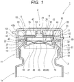
Fig. 1 is a cross sectional view of a container according to an embodiment of the present invention, with a cap attached to a container opening portion thereof. -
Fig. 2 is a cross sectional view of the container opening portion ofFig. 1 . -
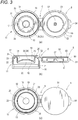
Fig. 3 is a plan view of a lid member and a main cap member including an annular wall portion, in the configuration of the cap ofFig. 1 ;Fig. 3(b) is a cross sectional view ofFig. 3(a); and Fig. 3(c) is a bottom view. -
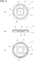
Fig. 4(a) is a plan view of a check valve in the configuration of the cap ofFig. 1 ;Fig. 4(b) is a cross sectional view ofFig. 4(a); and Fig. 4(c) is a bottom view. -
Fig. 5(a) is a plan view of an inner plug in the configuration of the cap ofFig. 1 ; andFig. 5(b) is a cross sectional view ofFig. 5(a) . - In the following, a mode for carrying out the present invention will be described in detail with reference to
Fig. 1 to Fig. 5 . - A
container 1 according to an embodiment of the present invention includes acontainer body 1a and acap 2. Thecap 2 is attached to a container openingportion 3 of thecontainer body 1a by capping. - As illustrated in
Fig. 1 , thecontainer body 1a is an easily deformable member, such as a tubular container, that is filled inside with a liquid content, or a flowable content having viscosity. Examples of the content include soy sauce, ponzu sauce, olive oil, dressings, mayonnaise, ketchup, ton-katsu (pork cutlet) sauce, and mustard paste. Thecontainer body 1a is the type of container from which the content is ejected by applying an internal pressure by, e.g., squeezing abody portion 7 thereof. The container openingportion 3 is formed in a cylindrical shape. Thecontainer body 1a includes a double container (including a container referred to as a delamination container) comprising an outer container and an inner container. The inner container is internally filled with the content. The inner container has flexibility so that the inner container becomes shrunk and deformed as the content decreases. In order to retain a reduced volume shape of the inner container, the inner container is configured such that outer air can be suctioned between the outer container and the inner container. - As illustrated in
Fig. 1 andFig. 2 , thecontainer body 1a is constructed from thebody portion 7, and the container openingportion 3 formed so as to be continuous with thebody portion 7. To the container openingportion 3, thecap 2 is fitted by capping. The container openingportion 3 is formed in a cylindrical shape as a whole. The container openingportion 3 is formed so as to be continuous with thebody portion 7 with substantially the same thickness. The container openingportion 3 is configured such that a plurality of opening portions (step portions) with different outer diameters is successively disposed along an axial direction. Specifically, the container openingportion 3 includes a largediameter opening portion 60, a smalldiameter opening portion 61, and a maximumdiameter opening portion 62. The large diameter openingportion 60 is disposed at the upper end, and extends in the axial direction. The smalldiameter opening portion 61 is disposed under the largediameter opening portion 60, has an outer diameter smaller than the largediameter opening portion 60, and extends in the axial direction. The maximumdiameter opening portion 62 is disposed under the smalldiameter opening portion 61, has an outer diameter greater than the largediameter opening portion 60, and extends in the axial direction. The largediameter opening portion 60 positioned at the upper end and the smalldiameter opening portion 61 are connected via a reduceddiameter opening portion 63 which is elastically deformable. The reduceddiameter opening portion 63 is gradually reduced in diameter continuously from the largediameter opening portion 60 downward. The smalldiameter opening portion 61 and the maximumdiameter opening portion 62 are connected via an extendeddiameter opening portion 64 which is elastically deformable. The extendeddiameter opening portion 64 is gradually extended in diameter continuously from the smalldiameter opening portion 61 downward. Under the maximumdiameter opening portion 62, asupport opening portion 65 is continuously formed, the support opening portion having a diameter smaller than the maximumdiameter opening portion 62 and greater than the largediameter opening portion 60 and extending in the axial direction. Between thesupport opening portion 65 and thebody portion 7, a recessedopening portion 66 with substantially the same diameter as the smalldiameter opening portion 61 is formed. When thecontainer opening portion 3 is capped with thecap 2, the outer peripheral area of the recessedopening portion 66 is held by a capping machine (not shown). - The
cap 2 according to the embodiment of the present invention is configured such that, immediately after a user squeezes thebody portion 7 of thecontainer body 1a to apply an internal pressure to thecontainer body 1a and uses an appropriate amount of the content, the inside of thecontainer body 1a is hermetically sealed by acheck valve 12 without the user operating thecap 2 manually. Specifically, thecap 2, as illustrated inFig. 1 , is configured from acap body 4 having acontent ejection hole 25, and alid member 5. Thelid member 5 is coupled, via ahinge 6, with amain cap member 11 constituting thecap body 4. Thecap 2 is constructed by assembling three constituent members: themain cap member 11, which, as illustrated inFig. 3 , includes anannular wall portion 10 and to which thelid member 5 is coupled; thecheck valve 12, illustrated inFig. 4 ; and aninner plug 13 illustrated inFig. 5 . Thelid member 5 may not be coupled with thecap body 4 by thehinge 6, and may be configured as a separate member. - As illustrated in
Fig. 1 , thecap body 4 is configured from: themain cap member 11, with which thecontainer opening portion 3 is capped and which has a cylindrical shape; theannular wall portion 10; thecheck valve 12; and theinner plug 13. Theannular wall portion 10 extends integrally from an inner wall surface of a cylindrical mainfitting wall portion 19 of themain cap member 11 toward the radial center and diagonally upward. Theannular wall portion 10 has theejection hole 25 at the radially central portion. Thecheck valve 12 is disposed over theannular wall portion 10. Thecheck valve 12 is configured to open and close theejection hole 25 as avalve portion 36 is detached from or seated on anannular valve seat 26 around theejection hole 25. Theinner plug 13 is disposed over thecheck valve 12. Theinner plug 13 communicates with theejection hole 25, and includes anejection passageway 41 for the content from theejection hole 25. Thecheck valve 12 is molded from a synthetic resin which is more elastic than a synthetic resin from which themain cap member 11 is molded. Specifically, themain cap member 11 including thelid member 12 is molded from polypropylene. Theinner plug 13 is molded from polyethylene. Thecheck valve 12 is molded from a polyethylene elastomer. - As illustrated in
Fig. 1 andFig. 3 , themain cap member 11 is configured from abody portion 18, the cylindrical mainfitting wall portion 19, and an annularhorizontal wall portion 20. The cylindrical mainfitting wall portion 19 is disposed concentrically on the inside of thebody portion 18. The annularhorizontal wall portion 20 connects the upper end of thebody portion 18 and the upper end of the cylindrical mainfitting wall portion 19. On a lower inner wall surface of thebody portion 18, a ridged lockingportion 21 is formed. Between the cylindrical mainfitting wall portion 19 and thebody portion 18, anannular space 22 is formed in which thecontainer opening portion 3 is fitted. In an outer peripheral portion of the upper surface of the annularhorizontal wall portion 20, an upwardly protruding annular projectingportion 17 is formed. In an upper inner wall surface of the cylindrical mainfitting wall portion 19, formed is an annularfitting recess portion 23 annularly extending in the circumferential direction. - The
annular wall portion 10 extends integrally from the entire areas in the circumferential direction of the lower inner wall surface of the cylindrical mainfitting wall portion 19, toward a radial center and diagonally upward. Theannular wall portion 10 has a truncated cone shape. By theannular wall portion 10 and the inner wall surface of the cylindrical mainfitting wall portion 19, aspace 24 with an open top is formed. Theannular wall portion 10 has theejection hole 25, which has a substantially circular shape, opened in the radially central portion thereof. Theejection hole 25 communicates with the interior of thecontainer opening portion 3. Around theejection hole 25, theannular valve seat 26 is formed. Theannular valve seat 26 is formed on an inverted cone shapedsurface 28. At one location in the annular valve seat 26 (inverted cone shaped surface 28) of theannular wall portion 10, acirculation groove 27 is formed in the radial direction. Thecirculation groove 27 is formed in a position on the opposite side from thehinge 6 side. Thecirculation groove 27 is formed with a substantially U-shaped cross section. - The annular
horizontal wall portion 20 has an outer diameter smaller than an outer diameter of thebody portion 18. On an outer wall surface of the annularhorizontal wall portion 20, an annularly extending ridged lockingportion 31 is formed in the circumferential direction. On the outer wall surface of the annularhorizontal wall portion 20, thelid member 5 is fitted. From a lower surface of the annularhorizontal wall portion 20, a cylindricalsub-fitting wall portion 32 descends concentrically in theannular space 22 between thebody portion 18 and the cylindrical mainfitting wall portion 19. In an annular space between the cylindricalsub-fitting wall portion 32 and thebody portion 18, a plurality of reinforcingribs 33 is formed at intervals in the circumferential direction. In the present embodiment, the reinforcingribs 33 are formed at eight locations. The formation of the plurality of reinforcingribs 33 makes it possible to maintain the rigidity of the cylindricalsub-fitting wall portion 32. The annular space is provided between the cylindricalsub-fitting wall portion 32 and thebody portion 18 because if the annular space were not provided and the cylindricalsub-fitting wall portion 32 were to be integrally provided from the inner wall surface of thebody portion 18, the cylindricalsub-fitting wall portion 32 would be thick, causing the problem of shrinkage and the like. - As illustrated in
Fig. 1 andFig. 4 , thecheck valve 12 is configured from acylindrical support portion 34, a plurality ofelastic pieces 35, thevalve portion 36, and a plurality of circulation holes 37. Thecylindrical support portion 34 abuts on the inner wall surface of the cylindrical mainfitting wall portion 19 of themain cap member 11. The plurality ofelastic pieces 35 extend integrally from the inner wall surface of thecylindrical support portion 34 toward radial center. Thevalve portion 36 is integrally connected to the distal end portion of each of theelastic pieces 35, and opens and closes theejection hole 25. The plurality of circulation holes 37 are provided between the respectiveelastic pieces 35. Through the circulation holes 37, the content from theejection hole 25 is circulated. - The
elastic pieces 35 extend from the upper inner wall surface of thecylindrical support portion 34 toward the radial center and diagonally downward, while slightly curving. In the present embodiment, theelastic pieces 35 are formed at four locations at a 90° pitch in the circumferential direction. Between theelastic pieces 35, the circulation holes 37 are formed at four locations at a 90° pitch. The distal end portion of each of theelastic pieces 35 is integrally connected to the upper edge of the outer peripheral portion of thevalve portion 36. Thevalve portion 36 has a dome shape. Specifically, thevalve portion 36 has a circular shape as viewed in plan, and includes an upwardly protruding curved wall portion. The outer peripheral portion of thevalve portion 36 is formed with an inverted cone shapedsurface 29 so as to be seated on the annular valve seat 26 (inverted cone shaped surface 28). From the upper surface of thevalve portion 36, a spherical protruding portion 38 rises. - As illustrated in
Fig. 1 andFig. 5 , theinner plug 13 is disposed over thecheck valve 12. Theinner plug 13 is configured from acylindrical support portion 40, acylindrical guide portion 42, and an annularhorizontal wall portion 43. Thecylindrical support portion 40 is fitted on the cylindrical mainfitting wall portion 19 of themain cap member 11. Thecylindrical guide portion 42 is concentrically disposed on the inside of thecylindrical support portion 40, and includes anejection passageway 41 therein. The annularhorizontal wall portion 43 integrally connects the upper end of thecylindrical support portion 40 and the lower end of thecylindrical guide portion 42. The annularhorizontal wall portion 43 is formed with anannular flange portion 43a which protrudes in the radial direction from the outer peripheral surface of thecylindrical support portion 40. Between the lower wall surface of the annularhorizontal wall portion 43 and the inner wall surface of thecylindrical support portion 40, a plurality of reinforcingribs 45 is formed at intervals in the circumferential direction. Thecylindrical support portion 40 is disposed over thecylindrical support portion 34 of thecheck valve 12. On the outer wall surface of thecylindrical support portion 40, anannular ridge portion 44 is formed extending in the circumferential direction. The peripheral wall portion of thecylindrical support portion 40 of theinner plug 13 and the peripheral wall portion of thecylindrical support portion 34 of thecheck valve 12 have substantially the same thickness. - As illustrated in
Fig. 1 andFig. 2 , thelid member 5 is integrally connected to thebody portion 18 of themain cap member 11 via thehinge 6. Thelid member 5 is configured from acylindrical body portion 50 and atop portion 51. Thecylindrical body portion 50 is connected to the outer wall surface of thebody portion 18 of themain cap member 11 via thehinge 6. Thetop portion 51 is integrally connected to the entire areas in the circumferential direction of the upper end of thebody portion 50. From the radially central portion of thetop portion 51, a cylindricalclose contact portion 52 descends. The cylindricalclose contact portion 52 is closely fitted in the upper end of thecylindrical guide portion 42 of theinner plug 13 of thecap body 4. Between thebody portion 50 and the cylindricalclose contact portion 52 of thetop portion 51, a cylindricalscattering suppression portion 55 descends. On the lower inner wall surface of thebody portion 50, formed is a ridged lockingportion 53 annularly extending in the circumferential direction. On the upper outer wall surface of thebody portion 50 on the opposite side from thehinge 6, a holdingportion 54 to be held by the user protrudes outward in a predetermined range in the circumferential direction. - A method for assembling the
cap 2 and attaching thecap 2 to thecontainer opening portion 3 will be described. - First, the
check valve 12 is installed on the upper surface of theannular wall portion 10 of themain cap member 11 from above. Specifically, thecheck valve 12 is disposed on the upper surface of theannular wall portion 10 in such a way that the outer wall surface of thecylindrical support portion 34 of thecheck valve 12 lies along the inner wall surface of the cylindrical mainfitting wall portion 19 of themain cap member 11. That is, thecheck valve 12 is installed from above into thespace 24 with an open top enclosed by theannular wall portion 10 and the inner wall surface of the cylindrical mainfitting wall portion 19. - Then, the
inner plug 13 is disposed in an opening portion 19a within the cylindrical mainfitting wall portion 19 of themain cap member 11. That is, theinner plug 13 is disposed such that the outer wall surface of thecylindrical support portion 40 of theinner plug 13 lies along the inner wall surface of the cylindrical mainfitting wall portion 19 of themain cap member 11. Theinner plug 13 is installed so as to press in thecheck valve 12. In this way, theannular ridge portion 44 provided on the outer wall surface of thecylindrical support portion 40 of theinner plug 13 is fitted in the annularfitting recess portion 23 provided in the inner wall surface of the cylindrical mainfitting wall portion 19 of themain cap member 11. Also, theannular flange portion 43a of theinner plug 13 abuts on the upper surface of the annularhorizontal wall portion 20. In this way, theinner plug 13 is installed. As a result, the outer peripheral portion (inverted cone shaped surface 29) of thevalve portion 36 of thecheck valve 12 closely contacts the annular valve seat 26 (inverted cone shaped surface 28) around theejection hole 25 of theannular wall portion 10. In this case, the lower end (outer peripheral portion) of thevalve portion 36 of thecheck valve 12 is positioned higher than the position before installation. Accordingly, due to the downward urging force (recovery force) of each of the curvedelastic pieces 35, the outer peripheral portion (inverted cone shaped surface 29) of thevalve portion 36 of thecheck valve 12 closely contacts the annular valve seat 26 (inverted cone shaped surface 28) around theejection hole 25 of theannular wall portion 10 so as to press the same. Immediately above the valve portion 36(ejection hole 25) of thecheck valve 12, thecylindrical guide portion 42 of theinner plug 13 is positioned. Further, at an interval in the radial direction from the outer peripheral surface of theannular flange portion 43a of theinner plug 13, the annular projectingportion 17 provided on the annularhorizontal wall portion 20 of themain cap member 11 is positioned. In this way, the assembly of thecap body 4 is completed. - Then, the
lid member 5 is capped over thecap body 4 by bending thehinge 6 so that thelid member 5 covers thecap body 4 from above. As a result, the ridged lockingportion 53 provided on thebody portion 50 of thelid member 5 becomes engaged across the ridged lockingportion 31 provided on the annularhorizontal wall portion 20 of themain cap member 11. Also, the cylindricalclose contact portion 52 provided on thetop portion 51 of thelid member 5 is closely fitted in the upper end of thecylindrical guide portion 42 of theinner plug 13 of thecap body 4. - Then, the
cap 2 is attached to thecontainer opening portion 3 by capping by inserting thecontainer opening portion 3 into theannular space 22 between the cylindrical mainfitting wall portion 19 and thebody portion 18 of thecap body 4. As a result, the inner wall surface of the cylindricalsub-fitting wall portion 32 descending from the annularhorizontal wall portion 20 of themain cap member 11 into theannular space 22, and the outer wall surface of the largediameter opening portion 60 of thecontainer opening portion 3 closely contact each other. Also, the outer wall surface of the cylindrical mainfitting wall portion 19 of themain cap member 11, and the inner wall surface of the smalldiameter opening portion 61 of thecontainer opening portion 3 closely contact each other. Further, the maximumdiameter opening portion 62 of thecontainer opening portion 3 moves across the ridged lockingportion 21 provided on the lower inner wall surface of thebody portion 18 of themain cap member 11, whereby one is disposed over the other in the vertical direction (with the maximumdiameter opening portion 62 being disposed over the ridged locking portion 21). In this way, the maximumdiameter opening portion 62 and the ridged lockingportion 21 are engaged with each other. The maximumdiameter opening portion 62 of thecontainer opening portion 3 also closely contacts the inner wall surface of thebody portion 18 of themain cap member 11. As a result, the reduceddiameter opening portion 63 and the extendeddiameter opening portion 64 of thecontainer opening portion 3 are pressed from below and thereby respectively elastically deformed. Due to the recovery force of each of the reduceddiameter opening portion 63 and the extendeddiameter opening portion 64, the pressing force from the inner wall surface of the smalldiameter opening portion 61 of thecontainer opening portion 3 toward the outer wall surface of the cylindrical mainfitting wall portion 19 of thecap 2 is increased. - During capping, the close contact portion 16 (seal portion) between the outer wall surface of the cylindrical main
fitting wall portion 19 of themain cap member 11 and the inner wall surface of the smalldiameter opening portion 61 of thecontainer opening portion 3 is positioned higher than a connectingportion 15 between theannular wall portion 10 and the cylindrical mainfitting wall portion 19. In addition, theannular wall portion 10 of themain cap member 11 extends toward the radial center and diagonally upward. Accordingly, when thecontainer opening portion 3 is inserted into theannular space 22 of themain cap member 11, inward elastic deformation of the cylindrical mainfitting wall portion 19 can be permitted compared with a configuration in which theannular wall portion 10 extends in the horizontal direction. Thus, thecontainer opening portion 3 can be smoothly inserted into theannular space 22 without resistance. After insertion, the outward recovery force of the cylindrical mainfitting wall portion 19 can be increased by theannular wall portion 10. Accordingly, the sealing between the outer wall surface of the cylindrical mainfitting wall portion 19 of themain cap member 11 and the inner wall surface of the smalldiameter opening portion 61 of thecontainer opening portion 3 can be further improved. In this way, the attachment of thecap 2 to thecontainer opening portion 3 by capping is completed. - The operation of the
cap 2 according to the embodiment of the present invention will be described. - When the content is used, first the
lid member 5 is opened to externally expose theinner plug 13 of thecap body 4. - Then, the
container 1 is inclined and placed in an ejecting state where theejection passageway 41 of theinner plug 13 faces downward, and thebody portion 7 of thecontainer body 1a is squeezed to apply internal pressure to thecontainer body 1a. In this way, the internal pressure of thecontainer body 1a acts on the entire area of the lower wall surface of thevalve portion 36 of thecheck valve 12. As a result, theelastic pieces 35 of thecheck valve 12 are elastically deformed and bent, whereby the outer peripheral portion (inverted cone shaped surface 29) of thevalve portion 36 is detached from the annular valve seat 26 (inverted cone shaped surface 28) around theejection hole 25 of theannular wall portion 10. Consequently, theejection hole 25 of theannular wall portion 10 is opened, and an appropriate amount of the content is ejected outwardly from within thecontainer opening portion 3, via theejection hole 25, the circulation holes 37 of thecheck valve 12, and theejection passageway 41 of theinner plug 13. - Thereafter, when the squeezing of the
body portion 7 of thecontainer body 1a is stopped, the internal pressure to thecontainer body 1a is released, and theelastic pieces 35 of thecheck valve 12 recover. The outer peripheral portion (inverted cone shaped surface 29) of thevalve portion 36 is seated on the annular valve seat 26 (inverted cone shaped surface 28) around theejection hole 25 of theannular wall portion 10, and theejection hole 25 of theannular wall portion 10 is closed by thevalve portion 36. In this case, the content that was not ejected outwardly from theejection passageway 41 of theinner plug 13 returns back into thecontainer body 1a via thecirculation groove 27. Thereafter, the pressing force from thevalve portion 26 to theannular valve seat 26 increases. Because thevalve portion 36 has elasticity, the opening area of thecirculation groove 27 decreases. Finally, the content blocks the opening of thecirculation groove 27 by surface tension, the opening being very small. Accordingly, the interior of thecontainer body 1a can be maintained in a hermetically sealed state. Thus, while the content in thecap body 4 that was not ejected is returned into thecontainer 1, the interior of thecontainer 1 can be quickly hermetically sealed immediately after use, without the user manually operating thecap 2, and the entry of air into the interior of thecontainer 1 can be suppressed. - Next, the
hinge 6 is bent and thelid member 5 is moved to cover thecap body 4 from above. In this way, the ridged lockingportion 53 provided on thebody portion 50 of thelid member 5 becomes engaged so as to move across the ridged lockingportion 31 provided on the annularhorizontal wall portion 20 of the cap body 4 (main cap member 11). Also, the cylindricalclose contact portion 52 provided on thetop portion 51 of thelid member 5 is closely fitted in the upper end of thecylindrical guide portion 42 of theinner plug 13 of thecap body 4. - As the
lid member 5 caps thecap body 4, the entry of foreign matter into the cap body 4 (between theinner plug 13 and thecheck valve 12 and annular wall portion 10) is suppressed, and the interior of thecontainer 1 is doubly hermetically sealed. In addition, because the interior of thecap body 4 is hermetically sealed by thelid member 5, any of the content that may have slightly remained in thespace 24 over theannular wall portion 10 does not become oxidized. - As described above, in the embodiment of the present invention, when the
cap 2 is capped on thecontainer opening portion 3 of thecontainer body 1a, the inner wall surface of the cylindricalsub-fitting wall portion 32 of themain cap member 11 and the outer wall surface of the largediameter opening portion 60 of thecontainer opening portion 3 closely contact each other. Also, the outer wall surface of the cylindrical mainfitting wall portion 19 of themain cap member 11 and the inner wall surface of the smalldiameter opening portion 61 of thecontainer opening portion 3 closely contact each other. Further, the maximumdiameter opening portion 62 of thecontainer opening portion 3 becomes engaged by moving across the ridged lockingportion 21 provided on the lower inner wall surface of thebody portion 18 of themain cap member 11. The maximumdiameter opening portion 62 of thecontainer opening portion 3 also closely contacts the inner wall surface of thebody portion 18 of themain cap member 11. As a result, the reduceddiameter opening portion 63 and the extendeddiameter opening portion 64 of thecontainer opening portion 3 are respectively elastically deformed by being pressed from below. Their recovery force increases the pressing force from the inner wall surface of the smalldiameter opening portion 61 of thecontainer opening portion 3 toward the outer wall surface of the cylindrical mainfitting wall portion 19 of thecap 2. In this way, the sealing between the outer wall surface of the cylindrical mainfitting wall portion 19 of thecap 2 and the inner wall surface of the smalldiameter opening portion 61 of thecontainer opening portion 3 can be improved. - In addition, in the embodiment of the present invention, the
main cap member 11 is provided with theannular wall portion 10. Theannular wall portion 10 extends integrally from the inner wall surface of the cylindrical mainfitting wall portion 19 toward the radial center and diagonally upward, and includes theejection hole 25 in the radially central portion. Theclose contact portion 16 between the outer wall surface of the cylindrical mainfitting wall portion 19 and the inner wall surface of the smalldiameter opening portion 61 of thecontainer opening portion 3 is positioned higher than the connectingportion 15 between the cylindrical mainfitting wall portion 19 and theannular wall portion 10. In this way, when thecontainer opening portion 3 is inserted into theannular space 22 of themain cap member 11, inward elastic deformation of the cylindrical mainfitting wall portion 19 can be permitted compared with a configuration in which theannular wall portion 10 extends in the horizontal direction. Accordingly, thecontainer opening portion 3 can be smoothly inserted into theannular space 22 without resistance. After insertion, the outward recovery force of the cylindrical mainfitting wall portion 19 can be increased by theannular wall portion 10. Accordingly, the sealing between the outer wall surface of the cylindrical mainfitting wall portion 19 of themain cap member 11 and the inner wall surface of the smalldiameter opening portion 61 of thecontainer opening portion 3 can be further improved. -
- 1
- Container
- 1a
- Container body
- 2
- Cap
- 3
- Container opening portion
- 10
- Annular wall portion
- 11
- Main cap member
- 12
- Check valve
- 15
- Connecting portion
- 16
- Close contact portion
- 18
- Body portion
- 19
- Cylindrical main fitting wall portion
- 21
- Ridged locking portion
- 22
- Annular space
- 25
- Ejection hole
- 26
- Annular valve seat
- 32
- Cylindrical sub-fitting wall portion
- 36
- Valve portion
- 60
- Large diameter opening portion
- 61
- Small diameter opening portion
- 62
- Maximum diameter opening portion
- 63
- Reduced diameter opening portion
- 64
- Extended diameter opening portion
Claims (5)
- A container with a cap attached to a container opening portion thereof by capping,
the container opening portion including a large diameter opening portion disposed at an upper end, and a small diameter opening portion disposed under the large diameter opening portion and having an outer diameter smaller than the large diameter opening portion,
the cap including an annular space which is provided between a body portion and a tubular main fitting wall portion disposed inside the body portion, and in which the container opening portion is fitted, and a tubular sub-fitting wall portion formed in the annular space, wherein
when the cap is capped on the container opening portion, an inner wall surface of the sub-fitting wall portion of the cap and an outer wall surface of the large diameter opening portion of the container opening portion closely contact each other, and an outer wall surface of the main fitting wall portion of the cap and an inner wall surface of the small diameter opening portion of the container opening portion closely contact each other. - The container according to claim 1, wherein
the container opening portion includes an extended diameter opening portion which gradually extends in diameter continuously downward from the small diameter opening portion, and
a maximum diameter opening portion extending downward in an axial direction continuously from the extended diameter opening portion, and having a diameter greater than a diameter of the large diameter opening portion, wherein
when the cap is capped on the container opening portion, the maximum diameter opening portion of the container opening portion becomes engaged by moving across a ridged locking portion provided on a lower inner wall surface of the body portion of the cap, and thereby causes the extended diameter opening portion to become elastically deformed by being pressed from below. - A cap attached to a container opening portion by capping, the cap comprising:an annular space which is disposed between a body portion and a tubular main fitting wall portion disposed inside the body portion, and in which the container opening portion is fitted; anda tubular sub-fitting wall portion which is formed in the annular space, and which an outer wall surface of an upper end of the container opening portion closely contacts.
- The cap according to claim 3, comprising:an annular wall portion which integrally extends from an inner wall surface of the main fitting wall portion toward a radial center and diagonally upward, and which includes an ejection hole in a radially central portion; anda check valve which is disposed over the annular wall portion and which is configured to open and close the ejection hole as a valve portion is detached from or seated on an annular valve seat around the ejection hole.
- The cap according to claim 4, comprising a close contact portion between an outer wall surface of the main fitting wall portion and an inner wall surface of the container opening portion, wherein
the close contact portion is positioned higher than a connecting portion between the main fitting wall portion and the annular wall portion.
Applications Claiming Priority (2)
| Application Number | Priority Date | Filing Date | Title |
|---|---|---|---|
| JP2015083306A JP6548440B2 (en) | 2015-04-15 | 2015-04-15 | Container and cap |
| PCT/JP2016/059659 WO2016167101A1 (en) | 2015-04-15 | 2016-03-25 | Container and cap |
Publications (3)
| Publication Number | Publication Date |
|---|---|
| EP3284693A1 true EP3284693A1 (en) | 2018-02-21 |
| EP3284693A4 EP3284693A4 (en) | 2019-03-06 |
| EP3284693B1 EP3284693B1 (en) | 2020-10-07 |
Family
ID=57125896
Family Applications (1)
| Application Number | Title | Priority Date | Filing Date |
|---|---|---|---|
| EP16779892.5A Active EP3284693B1 (en) | 2015-04-15 | 2016-03-25 | Container and cap |
Country Status (6)
| Country | Link |
|---|---|
| US (1) | US10689167B2 (en) |
| EP (1) | EP3284693B1 (en) |
| JP (1) | JP6548440B2 (en) |
| KR (1) | KR101933398B1 (en) |
| CN (1) | CN107531368B (en) |
| WO (1) | WO2016167101A1 (en) |
Families Citing this family (17)
| Publication number | Priority date | Publication date | Assignee | Title |
|---|---|---|---|---|
| JP6537319B2 (en) * | 2015-03-30 | 2019-07-03 | 東京ライト工業株式会社 | cap |
| JP6548440B2 (en) * | 2015-04-15 | 2019-07-24 | 東京ライト工業株式会社 | Container and cap |
| ES2887848T3 (en) | 2015-09-07 | 2021-12-28 | Mikasa Ind Co Ltd | Plug |
| US10822135B2 (en) * | 2015-12-03 | 2020-11-03 | Kyoraku Co., Ltd. | Delaminatable container |
| JP6710468B2 (en) * | 2016-12-28 | 2020-06-17 | 株式会社吉野工業所 | Discharge container |
| CN111386229B (en) | 2017-12-15 | 2021-12-24 | 赫斯基注塑系统有限公司 | Closure cap for a container |
| EP3722411B1 (en) | 2017-12-18 | 2024-10-16 | Terumo Kabushiki Kaisha | Fragile-object retaining device provided with protective mechanism |
| CN112334570B (en) | 2018-07-10 | 2024-02-09 | 泰尔茂株式会社 | Device for transferring implants |
| CN110921090B (en) * | 2018-09-20 | 2022-03-29 | 宏全国际股份有限公司 | Non-return bottle cap and non-return valve thereof |
| CN109466874B (en) * | 2018-12-05 | 2024-11-05 | 上海升村包装材料有限公司 | A spray bottle cap |
| GB201820292D0 (en) * | 2018-12-13 | 2019-01-30 | Obrist Closures Switzerland | Flow control insert |
| EP3896144A4 (en) | 2018-12-18 | 2022-02-16 | TERUMO Kabushiki Kaisha | GRIP TOOL |
| KR102076658B1 (en) * | 2019-05-31 | 2020-02-13 | 임종수 | A discharge device for discharging the liquid content in the tube container in a droplet form |
| CN214554535U (en) * | 2020-06-08 | 2021-11-02 | 璞真生活有限公司 | Essential Oil Nebulizer |
| MX2023003327A (en) * | 2020-10-15 | 2023-03-27 | Tetra Laval Holdings & Finance | LID AND NOZZLE ASSEMBLY FOR A CONTAINER AND CONTAINER THAT HAS A LID AND NOZZLE ASSEMBLY. |
| JP2022156281A (en) * | 2021-03-31 | 2022-10-14 | 本田技研工業株式会社 | sealed container |
| US20220378171A1 (en) * | 2021-05-27 | 2022-12-01 | L'oreal | Applicator having three-dimensional surface contact with reservoir |
Family Cites Families (53)
| Publication number | Priority date | Publication date | Assignee | Title |
|---|---|---|---|---|
| US3223269A (en) * | 1964-12-21 | 1965-12-14 | Owens Illinois Glass Co | Snap-on closure |
| US3572413A (en) * | 1969-06-19 | 1971-03-23 | Jay G Livingstone | Container and snap-on cover |
| USRE28521E (en) * | 1970-02-21 | 1975-08-19 | Container construction | |
| US3805994A (en) * | 1971-09-13 | 1974-04-23 | Great American Foods Inc | Containers and plastic snap-closures therefor for use with automatic capping machines |
| JPS6238831A (en) | 1985-08-14 | 1987-02-19 | Yamaha Motor Co Ltd | Exhaust device for two-cycle engine of vehicle such as motorcycle |
| JPH0311159Y2 (en) * | 1985-08-27 | 1991-03-19 | ||
| US5033647A (en) * | 1990-03-09 | 1991-07-23 | Allergan, Inc. | Value controlled squeezable fluid dispenser |
| JP2841707B2 (en) | 1990-05-16 | 1998-12-24 | 松下電器産業株式会社 | Thermal head drive |
| JPH0421465U (en) * | 1990-06-12 | 1992-02-24 | ||
| JP2578040Y2 (en) * | 1991-06-05 | 1998-08-06 | 三笠産業株式会社 | Container stopper |
| IT221941Z2 (en) | 1991-10-10 | 1994-12-29 | Sofar Spa | NON-RETURN VALVE CAN BE USED IN PARTICULAR IN A LIQUID PRESSURE DISPENSING CONTAINER |
| US6536616B2 (en) * | 1995-02-09 | 2003-03-25 | Portola Packaging, Inc. | Container neck finish and method and apparatus for forming same and cap for use thereon |
| GB2335624B (en) * | 1995-02-09 | 1999-11-10 | Portola Packaging Inc | Blow molded container neck and cap |
| WO1996024526A1 (en) * | 1995-02-09 | 1996-08-15 | Portola Packaging, Inc. | Blow molded container neck and cap |
| FR2769595B1 (en) * | 1997-10-10 | 1999-11-19 | Oreal | DISTRIBUTION HEAD WITH IMPROVED AIR INTAKE, AND PACKAGING AND DISTRIBUTION ASSEMBLY PROVIDED WITH SUCH A HEAD |
| JP4485627B2 (en) * | 1999-10-08 | 2010-06-23 | 大成化工株式会社 | Laminated peeling bottle and pump container |
| JP4586223B2 (en) * | 1999-11-19 | 2010-11-24 | 大成化工株式会社 | Discharge container |
| FR2806705B1 (en) * | 2000-03-27 | 2002-05-03 | Oreal | DISPENSING CAPSULE AND CONTAINER PROVIDED WITH SUCH A CAPSULE |
| FR2810641B1 (en) * | 2000-06-21 | 2002-10-18 | Cebal | FLEXIBLE TUBE PROVIDED WITH A LARGE DIAMETER NECK AND RIGID TIP TO BE FIXED ON SAID TUBE |
| DE20013287U1 (en) * | 2000-08-02 | 2001-01-11 | MegaPlast GmbH & Co. KG, 78052 Villingen-Schwenningen | Automatic closure for elastically deformable containers |
| US6536617B2 (en) * | 2001-02-15 | 2003-03-25 | Colgate-Palmolive Company | Bottle with closure holding structure |
| CN2471720Y (en) * | 2001-04-13 | 2002-01-16 | 王瑞才 | Expand-proof cover for chemical material container |
| US6616012B2 (en) * | 2001-07-27 | 2003-09-09 | Richard C. G. Dark | Fluid dispensing valve and method of use |
| US6749092B2 (en) * | 2001-08-10 | 2004-06-15 | Seaquist Closures Foreign, Inc. | Deformable dispensing valve |
| JP4129811B2 (en) * | 2002-04-30 | 2008-08-06 | 株式会社吉野工業所 | Dispensing container |
| DE10308599B4 (en) * | 2003-02-27 | 2006-02-16 | Weener Plastik Gmbh & Co Kg | cap |
| PL1622814T3 (en) * | 2003-05-07 | 2008-07-31 | Obrist Closures Switzerland | Valve closure |
| JP4522111B2 (en) * | 2004-02-25 | 2010-08-11 | 三笠産業株式会社 | Container cap |
| US7703621B2 (en) * | 2005-08-25 | 2010-04-27 | Union Street Brand Packaging Llc | Moisture retention seal |
| CN101535143B (en) | 2006-04-28 | 2012-07-04 | 东罐兴业株式会社 | Lids and containers with lids |
| US7743952B2 (en) * | 2006-10-18 | 2010-06-29 | Stull Technologies, Inc. | Double bead sealing system for container closure |
| US7874466B2 (en) * | 2006-11-07 | 2011-01-25 | The Procter & Gamble Company | Package comprising push-pull closure and slit valve |
| US8056744B2 (en) * | 2007-01-12 | 2011-11-15 | Phoenix Closures, Inc. | Closure with ring ribs |
| US8397956B2 (en) * | 2007-03-27 | 2013-03-19 | Aptargroup, Inc. | Dispensing valve with improved dispensing |
| JP5198888B2 (en) | 2008-01-31 | 2013-05-15 | 株式会社吉野工業所 | Pouring cap |
| CN201195602Y (en) * | 2008-03-24 | 2009-02-18 | 赖文生 | Structure of bottle cap and bottle mouth |
| BR112013004938B8 (en) * | 2010-09-02 | 2020-10-13 | Kraft Foods Group Brands Llc | containers for dispensing beverage concentrates |
| JP5667010B2 (en) * | 2011-06-09 | 2015-02-12 | 株式会社吉野工業所 | Discharge container |
| ITVI20110267A1 (en) * | 2011-10-05 | 2013-04-06 | Giflor S R L | CONTAINER FOR PRODUCTS, IN PARTICULAR FOR FLUID PRODUCTS. |
| CA2853508C (en) * | 2011-10-31 | 2020-10-27 | Yoshino Kogyosho Co., Ltd. | Discharge container |
| SG11201403052TA (en) * | 2011-12-26 | 2014-10-30 | Yoshino Kogyosho Co Ltd | Squeezable container |
| CN202967002U (en) * | 2012-12-25 | 2013-06-05 | 河北德容塑料包装容器有限公司 | Bottleneck sealing device for plastic bottles |
| JP6198392B2 (en) * | 2012-12-27 | 2017-09-20 | 花王株式会社 | Cap seal structure |
| US9669973B2 (en) * | 2013-06-28 | 2017-06-06 | Yoshino Kogyosho Co., Ltd. | Double-walled container |
| CN203889189U (en) * | 2014-04-17 | 2014-10-22 | 内蒙古伊利实业集团股份有限公司 | Sealing structure for inner plugging type bottle cap and bottleneck of extrusion blow-molded bottle |
| US9974419B2 (en) * | 2014-04-23 | 2018-05-22 | The Clorox Company | Disinfecting wipes dispenser |
| KR102110129B1 (en) * | 2014-05-14 | 2020-06-08 | 도쿄 라이트 고교 가부시키가이샤 | Cap |
| GB201601237D0 (en) * | 2016-01-22 | 2016-03-09 | Rieke Packaging Systems Ltd | Dispensing closures and dispensers |
| JP6537319B2 (en) * | 2015-03-30 | 2019-07-03 | 東京ライト工業株式会社 | cap |
| JP6548440B2 (en) * | 2015-04-15 | 2019-07-24 | 東京ライト工業株式会社 | Container and cap |
| GB201516189D0 (en) * | 2015-09-14 | 2015-10-28 | Obrist Closures Switzerland | Head stand closure with a tamper-evident seal |
| GB201601232D0 (en) * | 2016-01-22 | 2016-03-09 | Rieke Packaging Systems Ltd | Dispensing closures and dispensers |
| US10781017B2 (en) * | 2016-05-20 | 2020-09-22 | Tokyo Light Industry Co., Ltd. | Cap and discharge container |
-
2015
- 2015-04-15 JP JP2015083306A patent/JP6548440B2/en active Active
-
2016
- 2016-03-25 WO PCT/JP2016/059659 patent/WO2016167101A1/en not_active Ceased
- 2016-03-25 EP EP16779892.5A patent/EP3284693B1/en active Active
- 2016-03-25 CN CN201680021658.8A patent/CN107531368B/en active Active
- 2016-03-25 US US15/566,091 patent/US10689167B2/en active Active
- 2016-03-25 KR KR1020177032918A patent/KR101933398B1/en active Active
Also Published As
| Publication number | Publication date |
|---|---|
| JP2016203985A (en) | 2016-12-08 |
| WO2016167101A1 (en) | 2016-10-20 |
| CN107531368B (en) | 2020-08-18 |
| KR101933398B1 (en) | 2018-12-28 |
| CN107531368A (en) | 2018-01-02 |
| KR20170136630A (en) | 2017-12-11 |
| JP6548440B2 (en) | 2019-07-24 |
| US10689167B2 (en) | 2020-06-23 |
| EP3284693A4 (en) | 2019-03-06 |
| EP3284693B1 (en) | 2020-10-07 |
| US20180111724A1 (en) | 2018-04-26 |
Similar Documents
| Publication | Publication Date | Title |
|---|---|---|
| US10689167B2 (en) | Container and cap | |
| EP3279109B1 (en) | Cap | |
| KR102110129B1 (en) | Cap | |
| EP2539245B1 (en) | Packaging | |
| EP3447000B1 (en) | Cap and discharge container | |
| JP5963323B2 (en) | cap | |
| KR100561958B1 (en) | Dispensing enclosure with integral self-sealing valve | |
| JP2017001700A (en) | cap | |
| JP2017193352A (en) | cap | |
| KR102102223B1 (en) | Airless type cosmetics container using eco pump | |
| JP2013230838A (en) | Container with cap | |
| JP5959570B2 (en) | cap | |
| JP2015217952A (en) | cap | |
| JP2016055921A (en) | cap | |
| JP2019026378A (en) | cap | |
| JP5123908B2 (en) | Application container | |
| JP2016216050A (en) | cap | |
| JP7076334B2 (en) | container | |
| CN109809047B (en) | Container for discharging liquid | |
| JP2017165449A (en) | cap |
Legal Events
| Date | Code | Title | Description |
|---|---|---|---|
| STAA | Information on the status of an ep patent application or granted ep patent |
Free format text: STATUS: THE INTERNATIONAL PUBLICATION HAS BEEN MADE |
|
| PUAI | Public reference made under article 153(3) epc to a published international application that has entered the european phase |
Free format text: ORIGINAL CODE: 0009012 |
|
| STAA | Information on the status of an ep patent application or granted ep patent |
Free format text: STATUS: REQUEST FOR EXAMINATION WAS MADE |
|
| 17P | Request for examination filed |
Effective date: 20171020 |
|
| AK | Designated contracting states |
Kind code of ref document: A1 Designated state(s): AL AT BE BG CH CY CZ DE DK EE ES FI FR GB GR HR HU IE IS IT LI LT LU LV MC MK MT NL NO PL PT RO RS SE SI SK SM TR |
|
| AX | Request for extension of the european patent |
Extension state: BA ME |
|
| DAV | Request for validation of the european patent (deleted) | ||
| DAX | Request for extension of the european patent (deleted) | ||
| RIC1 | Information provided on ipc code assigned before grant |
Ipc: B65D 41/18 20060101ALI20181026BHEP Ipc: B65D 41/28 20060101AFI20181026BHEP Ipc: B65D 47/08 20060101ALI20181026BHEP Ipc: B65D 41/16 20060101ALI20181026BHEP Ipc: B65D 49/02 20060101ALI20181026BHEP Ipc: B65D 47/20 20060101ALI20181026BHEP |
|
| A4 | Supplementary search report drawn up and despatched |
Effective date: 20190205 |
|
| RIC1 | Information provided on ipc code assigned before grant |
Ipc: B65D 41/16 20060101ALI20190130BHEP Ipc: B65D 49/02 20060101ALI20190130BHEP Ipc: B65D 41/18 20060101ALI20190130BHEP Ipc: B65D 47/20 20060101ALI20190130BHEP Ipc: B65D 41/28 20060101AFI20190130BHEP Ipc: B65D 47/08 20060101ALI20190130BHEP |
|
| RIC1 | Information provided on ipc code assigned before grant |
Ipc: B65D 41/18 20060101ALI20200221BHEP Ipc: B65D 41/16 20060101ALI20200221BHEP Ipc: B65D 41/28 20060101AFI20200221BHEP Ipc: B65D 49/02 20060101ALI20200221BHEP Ipc: B65D 47/08 20060101ALI20200221BHEP Ipc: B65D 47/20 20060101ALI20200221BHEP |
|
| GRAP | Despatch of communication of intention to grant a patent |
Free format text: ORIGINAL CODE: EPIDOSNIGR1 |
|
| STAA | Information on the status of an ep patent application or granted ep patent |
Free format text: STATUS: GRANT OF PATENT IS INTENDED |
|
| INTG | Intention to grant announced |
Effective date: 20200430 |
|
| GRAS | Grant fee paid |
Free format text: ORIGINAL CODE: EPIDOSNIGR3 |
|
| GRAA | (expected) grant |
Free format text: ORIGINAL CODE: 0009210 |
|
| STAA | Information on the status of an ep patent application or granted ep patent |
Free format text: STATUS: THE PATENT HAS BEEN GRANTED |
|
| AK | Designated contracting states |
Kind code of ref document: B1 Designated state(s): AL AT BE BG CH CY CZ DE DK EE ES FI FR GB GR HR HU IE IS IT LI LT LU LV MC MK MT NL NO PL PT RO RS SE SI SK SM TR |
|
| REG | Reference to a national code |
Ref country code: GB Ref legal event code: FG4D |
|
| REG | Reference to a national code |
Ref country code: CH Ref legal event code: EP Ref country code: AT Ref legal event code: REF Ref document number: 1320960 Country of ref document: AT Kind code of ref document: T Effective date: 20201015 |
|
| REG | Reference to a national code |
Ref country code: DE Ref legal event code: R096 Ref document number: 602016045447 Country of ref document: DE |
|
| REG | Reference to a national code |
Ref country code: IE Ref legal event code: FG4D |
|
| REG | Reference to a national code |
Ref country code: NL Ref legal event code: MP Effective date: 20201007 |
|
| REG | Reference to a national code |
Ref country code: AT Ref legal event code: MK05 Ref document number: 1320960 Country of ref document: AT Kind code of ref document: T Effective date: 20201007 |
|
| PG25 | Lapsed in a contracting state [announced via postgrant information from national office to epo] |
Ref country code: GR Free format text: LAPSE BECAUSE OF FAILURE TO SUBMIT A TRANSLATION OF THE DESCRIPTION OR TO PAY THE FEE WITHIN THE PRESCRIBED TIME-LIMIT Effective date: 20210108 Ref country code: FI Free format text: LAPSE BECAUSE OF FAILURE TO SUBMIT A TRANSLATION OF THE DESCRIPTION OR TO PAY THE FEE WITHIN THE PRESCRIBED TIME-LIMIT Effective date: 20201007 Ref country code: RS Free format text: LAPSE BECAUSE OF FAILURE TO SUBMIT A TRANSLATION OF THE DESCRIPTION OR TO PAY THE FEE WITHIN THE PRESCRIBED TIME-LIMIT Effective date: 20201007 Ref country code: PT Free format text: LAPSE BECAUSE OF FAILURE TO SUBMIT A TRANSLATION OF THE DESCRIPTION OR TO PAY THE FEE WITHIN THE PRESCRIBED TIME-LIMIT Effective date: 20210208 Ref country code: NL Free format text: LAPSE BECAUSE OF FAILURE TO SUBMIT A TRANSLATION OF THE DESCRIPTION OR TO PAY THE FEE WITHIN THE PRESCRIBED TIME-LIMIT Effective date: 20201007 Ref country code: NO Free format text: LAPSE BECAUSE OF FAILURE TO SUBMIT A TRANSLATION OF THE DESCRIPTION OR TO PAY THE FEE WITHIN THE PRESCRIBED TIME-LIMIT Effective date: 20210107 |
|
| REG | Reference to a national code |
Ref country code: LT Ref legal event code: MG4D |
|
| PG25 | Lapsed in a contracting state [announced via postgrant information from national office to epo] |
Ref country code: SE Free format text: LAPSE BECAUSE OF FAILURE TO SUBMIT A TRANSLATION OF THE DESCRIPTION OR TO PAY THE FEE WITHIN THE PRESCRIBED TIME-LIMIT Effective date: 20201007 Ref country code: PL Free format text: LAPSE BECAUSE OF FAILURE TO SUBMIT A TRANSLATION OF THE DESCRIPTION OR TO PAY THE FEE WITHIN THE PRESCRIBED TIME-LIMIT Effective date: 20201007 Ref country code: LV Free format text: LAPSE BECAUSE OF FAILURE TO SUBMIT A TRANSLATION OF THE DESCRIPTION OR TO PAY THE FEE WITHIN THE PRESCRIBED TIME-LIMIT Effective date: 20201007 Ref country code: IS Free format text: LAPSE BECAUSE OF FAILURE TO SUBMIT A TRANSLATION OF THE DESCRIPTION OR TO PAY THE FEE WITHIN THE PRESCRIBED TIME-LIMIT Effective date: 20210207 Ref country code: BG Free format text: LAPSE BECAUSE OF FAILURE TO SUBMIT A TRANSLATION OF THE DESCRIPTION OR TO PAY THE FEE WITHIN THE PRESCRIBED TIME-LIMIT Effective date: 20210107 Ref country code: ES Free format text: LAPSE BECAUSE OF FAILURE TO SUBMIT A TRANSLATION OF THE DESCRIPTION OR TO PAY THE FEE WITHIN THE PRESCRIBED TIME-LIMIT Effective date: 20201007 Ref country code: AT Free format text: LAPSE BECAUSE OF FAILURE TO SUBMIT A TRANSLATION OF THE DESCRIPTION OR TO PAY THE FEE WITHIN THE PRESCRIBED TIME-LIMIT Effective date: 20201007 |
|
| PG25 | Lapsed in a contracting state [announced via postgrant information from national office to epo] |
Ref country code: HR Free format text: LAPSE BECAUSE OF FAILURE TO SUBMIT A TRANSLATION OF THE DESCRIPTION OR TO PAY THE FEE WITHIN THE PRESCRIBED TIME-LIMIT Effective date: 20201007 |
|
| REG | Reference to a national code |
Ref country code: DE Ref legal event code: R097 Ref document number: 602016045447 Country of ref document: DE |
|
| PG25 | Lapsed in a contracting state [announced via postgrant information from national office to epo] |
Ref country code: RO Free format text: LAPSE BECAUSE OF FAILURE TO SUBMIT A TRANSLATION OF THE DESCRIPTION OR TO PAY THE FEE WITHIN THE PRESCRIBED TIME-LIMIT Effective date: 20201007 Ref country code: SK Free format text: LAPSE BECAUSE OF FAILURE TO SUBMIT A TRANSLATION OF THE DESCRIPTION OR TO PAY THE FEE WITHIN THE PRESCRIBED TIME-LIMIT Effective date: 20201007 Ref country code: EE Free format text: LAPSE BECAUSE OF FAILURE TO SUBMIT A TRANSLATION OF THE DESCRIPTION OR TO PAY THE FEE WITHIN THE PRESCRIBED TIME-LIMIT Effective date: 20201007 Ref country code: CZ Free format text: LAPSE BECAUSE OF FAILURE TO SUBMIT A TRANSLATION OF THE DESCRIPTION OR TO PAY THE FEE WITHIN THE PRESCRIBED TIME-LIMIT Effective date: 20201007 Ref country code: SM Free format text: LAPSE BECAUSE OF FAILURE TO SUBMIT A TRANSLATION OF THE DESCRIPTION OR TO PAY THE FEE WITHIN THE PRESCRIBED TIME-LIMIT Effective date: 20201007 Ref country code: LT Free format text: LAPSE BECAUSE OF FAILURE TO SUBMIT A TRANSLATION OF THE DESCRIPTION OR TO PAY THE FEE WITHIN THE PRESCRIBED TIME-LIMIT Effective date: 20201007 |
|
| PLBE | No opposition filed within time limit |
Free format text: ORIGINAL CODE: 0009261 |
|
| STAA | Information on the status of an ep patent application or granted ep patent |
Free format text: STATUS: NO OPPOSITION FILED WITHIN TIME LIMIT |
|
| PG25 | Lapsed in a contracting state [announced via postgrant information from national office to epo] |
Ref country code: DK Free format text: LAPSE BECAUSE OF FAILURE TO SUBMIT A TRANSLATION OF THE DESCRIPTION OR TO PAY THE FEE WITHIN THE PRESCRIBED TIME-LIMIT Effective date: 20201007 |
|
| 26N | No opposition filed |
Effective date: 20210708 |
|
| PG25 | Lapsed in a contracting state [announced via postgrant information from national office to epo] |
Ref country code: MC Free format text: LAPSE BECAUSE OF FAILURE TO SUBMIT A TRANSLATION OF THE DESCRIPTION OR TO PAY THE FEE WITHIN THE PRESCRIBED TIME-LIMIT Effective date: 20201007 Ref country code: AL Free format text: LAPSE BECAUSE OF FAILURE TO SUBMIT A TRANSLATION OF THE DESCRIPTION OR TO PAY THE FEE WITHIN THE PRESCRIBED TIME-LIMIT Effective date: 20201007 Ref country code: IT Free format text: LAPSE BECAUSE OF FAILURE TO SUBMIT A TRANSLATION OF THE DESCRIPTION OR TO PAY THE FEE WITHIN THE PRESCRIBED TIME-LIMIT Effective date: 20201007 |
|
| REG | Reference to a national code |
Ref country code: CH Ref legal event code: PL |
|
| PG25 | Lapsed in a contracting state [announced via postgrant information from national office to epo] |
Ref country code: SI Free format text: LAPSE BECAUSE OF FAILURE TO SUBMIT A TRANSLATION OF THE DESCRIPTION OR TO PAY THE FEE WITHIN THE PRESCRIBED TIME-LIMIT Effective date: 20201007 |
|
| REG | Reference to a national code |
Ref country code: BE Ref legal event code: MM Effective date: 20210331 |
|
| PG25 | Lapsed in a contracting state [announced via postgrant information from national office to epo] |
Ref country code: CH Free format text: LAPSE BECAUSE OF NON-PAYMENT OF DUE FEES Effective date: 20210331 Ref country code: LI Free format text: LAPSE BECAUSE OF NON-PAYMENT OF DUE FEES Effective date: 20210331 Ref country code: LU Free format text: LAPSE BECAUSE OF NON-PAYMENT OF DUE FEES Effective date: 20210325 Ref country code: IE Free format text: LAPSE BECAUSE OF NON-PAYMENT OF DUE FEES Effective date: 20210325 |
|
| PG25 | Lapsed in a contracting state [announced via postgrant information from national office to epo] |
Ref country code: IS Free format text: LAPSE BECAUSE OF FAILURE TO SUBMIT A TRANSLATION OF THE DESCRIPTION OR TO PAY THE FEE WITHIN THE PRESCRIBED TIME-LIMIT Effective date: 20210207 |
|
| PG25 | Lapsed in a contracting state [announced via postgrant information from national office to epo] |
Ref country code: BE Free format text: LAPSE BECAUSE OF NON-PAYMENT OF DUE FEES Effective date: 20210331 |
|
| PG25 | Lapsed in a contracting state [announced via postgrant information from national office to epo] |
Ref country code: CY Free format text: LAPSE BECAUSE OF FAILURE TO SUBMIT A TRANSLATION OF THE DESCRIPTION OR TO PAY THE FEE WITHIN THE PRESCRIBED TIME-LIMIT Effective date: 20201007 |
|
| PG25 | Lapsed in a contracting state [announced via postgrant information from national office to epo] |
Ref country code: HU Free format text: LAPSE BECAUSE OF FAILURE TO SUBMIT A TRANSLATION OF THE DESCRIPTION OR TO PAY THE FEE WITHIN THE PRESCRIBED TIME-LIMIT; INVALID AB INITIO Effective date: 20160325 |
|
| PG25 | Lapsed in a contracting state [announced via postgrant information from national office to epo] |
Ref country code: MK Free format text: LAPSE BECAUSE OF FAILURE TO SUBMIT A TRANSLATION OF THE DESCRIPTION OR TO PAY THE FEE WITHIN THE PRESCRIBED TIME-LIMIT Effective date: 20201007 |
|
| PGFP | Annual fee paid to national office [announced via postgrant information from national office to epo] |
Ref country code: GB Payment date: 20240320 Year of fee payment: 9 |
|
| PGFP | Annual fee paid to national office [announced via postgrant information from national office to epo] |
Ref country code: FR Payment date: 20240328 Year of fee payment: 9 |
|
| PG25 | Lapsed in a contracting state [announced via postgrant information from national office to epo] |
Ref country code: TR Free format text: LAPSE BECAUSE OF FAILURE TO SUBMIT A TRANSLATION OF THE DESCRIPTION OR TO PAY THE FEE WITHIN THE PRESCRIBED TIME-LIMIT Effective date: 20201007 |
|
| PG25 | Lapsed in a contracting state [announced via postgrant information from national office to epo] |
Ref country code: MT Free format text: LAPSE BECAUSE OF FAILURE TO SUBMIT A TRANSLATION OF THE DESCRIPTION OR TO PAY THE FEE WITHIN THE PRESCRIBED TIME-LIMIT Effective date: 20201007 |
|
| GBPC | Gb: european patent ceased through non-payment of renewal fee |
Effective date: 20250325 |
|
| PG25 | Lapsed in a contracting state [announced via postgrant information from national office to epo] |
Ref country code: GB Free format text: LAPSE BECAUSE OF NON-PAYMENT OF DUE FEES Effective date: 20250325 |
|
| PG25 | Lapsed in a contracting state [announced via postgrant information from national office to epo] |
Ref country code: FR Free format text: LAPSE BECAUSE OF NON-PAYMENT OF DUE FEES Effective date: 20250331 |
|
| PGFP | Annual fee paid to national office [announced via postgrant information from national office to epo] |
Ref country code: DE Payment date: 20260319 Year of fee payment: 11 |