EP3284657A1 - Working vehicle - Google Patents
Working vehicle Download PDFInfo
- Publication number
- EP3284657A1 EP3284657A1 EP16776338.2A EP16776338A EP3284657A1 EP 3284657 A1 EP3284657 A1 EP 3284657A1 EP 16776338 A EP16776338 A EP 16776338A EP 3284657 A1 EP3284657 A1 EP 3284657A1
- Authority
- EP
- European Patent Office
- Prior art keywords
- engine hood
- brake
- brake pedal
- operation unit
- dashboard
- Prior art date
- Legal status (The legal status is an assumption and is not a legal conclusion. Google has not performed a legal analysis and makes no representation as to the accuracy of the status listed.)
- Granted
Links
- 230000005540 biological transmission Effects 0.000 claims description 40
- 230000003213 activating effect Effects 0.000 claims description 9
- 239000007789 gas Substances 0.000 description 31
- 239000000446 fuel Substances 0.000 description 13
- 239000004071 soot Substances 0.000 description 12
- 238000001816 cooling Methods 0.000 description 11
- 238000001514 detection method Methods 0.000 description 11
- 230000004048 modification Effects 0.000 description 11
- 238000012986 modification Methods 0.000 description 11
- MWUXSHHQAYIFBG-UHFFFAOYSA-N nitrogen oxide Inorganic materials O=[N] MWUXSHHQAYIFBG-UHFFFAOYSA-N 0.000 description 9
- 239000013618 particulate matter Substances 0.000 description 8
- 239000003054 catalyst Substances 0.000 description 5
- 230000003647 oxidation Effects 0.000 description 5
- 238000007254 oxidation reaction Methods 0.000 description 5
- 239000002828 fuel tank Substances 0.000 description 4
- 239000002245 particle Substances 0.000 description 4
- MGWGWNFMUOTEHG-UHFFFAOYSA-N 4-(3,5-dimethylphenyl)-1,3-thiazol-2-amine Chemical compound CC1=CC(C)=CC(C=2N=C(N)SC=2)=C1 MGWGWNFMUOTEHG-UHFFFAOYSA-N 0.000 description 3
- 230000006835 compression Effects 0.000 description 3
- 238000007906 compression Methods 0.000 description 3
- JCXJVPUVTGWSNB-UHFFFAOYSA-N nitrogen dioxide Inorganic materials O=[N]=O JCXJVPUVTGWSNB-UHFFFAOYSA-N 0.000 description 3
- 230000000694 effects Effects 0.000 description 2
- 238000002347 injection Methods 0.000 description 2
- 239000007924 injection Substances 0.000 description 2
- 238000000034 method Methods 0.000 description 2
- BASFCYQUMIYNBI-UHFFFAOYSA-N platinum Chemical compound [Pt] BASFCYQUMIYNBI-UHFFFAOYSA-N 0.000 description 2
- 238000003825 pressing Methods 0.000 description 2
- 238000000746 purification Methods 0.000 description 2
- 238000011144 upstream manufacturing Methods 0.000 description 2
- IJGRMHOSHXDMSA-UHFFFAOYSA-N Atomic nitrogen Chemical compound N#N IJGRMHOSHXDMSA-UHFFFAOYSA-N 0.000 description 1
- 239000004215 Carbon black (E152) Substances 0.000 description 1
- 229910000831 Steel Inorganic materials 0.000 description 1
- 238000009825 accumulation Methods 0.000 description 1
- 230000001174 ascending effect Effects 0.000 description 1
- QVGXLLKOCUKJST-UHFFFAOYSA-N atomic oxygen Chemical compound [O] QVGXLLKOCUKJST-UHFFFAOYSA-N 0.000 description 1
- 238000006243 chemical reaction Methods 0.000 description 1
- 238000002485 combustion reaction Methods 0.000 description 1
- 238000010276 construction Methods 0.000 description 1
- 239000000498 cooling water Substances 0.000 description 1
- 230000008021 deposition Effects 0.000 description 1
- 230000006866 deterioration Effects 0.000 description 1
- 229910001873 dinitrogen Inorganic materials 0.000 description 1
- 239000000428 dust Substances 0.000 description 1
- 230000005611 electricity Effects 0.000 description 1
- 230000002349 favourable effect Effects 0.000 description 1
- 238000001914 filtration Methods 0.000 description 1
- 239000011491 glass wool Substances 0.000 description 1
- 238000011905 homologation Methods 0.000 description 1
- 229930195733 hydrocarbon Natural products 0.000 description 1
- 150000002430 hydrocarbons Chemical class 0.000 description 1
- 239000011810 insulating material Substances 0.000 description 1
- 229910052751 metal Inorganic materials 0.000 description 1
- 239000002184 metal Substances 0.000 description 1
- 230000001590 oxidative effect Effects 0.000 description 1
- 239000001301 oxygen Substances 0.000 description 1
- 229910052760 oxygen Inorganic materials 0.000 description 1
- 238000005192 partition Methods 0.000 description 1
- 230000000149 penetrating effect Effects 0.000 description 1
- 229910052697 platinum Inorganic materials 0.000 description 1
- 230000001681 protective effect Effects 0.000 description 1
- 239000003870 refractory metal Substances 0.000 description 1
- 230000000452 restraining effect Effects 0.000 description 1
- 230000000717 retained effect Effects 0.000 description 1
- 239000000243 solution Substances 0.000 description 1
- 239000010959 steel Substances 0.000 description 1
- 239000000126 substance Substances 0.000 description 1
- 125000000391 vinyl group Chemical group [H]C([*])=C([H])[H] 0.000 description 1
- 229920002554 vinyl polymer Polymers 0.000 description 1
- 238000003466 welding Methods 0.000 description 1
Images


Classifications
-
- B—PERFORMING OPERATIONS; TRANSPORTING
- B62—LAND VEHICLES FOR TRAVELLING OTHERWISE THAN ON RAILS
- B62D—MOTOR VEHICLES; TRAILERS
- B62D25/00—Superstructure or monocoque structure sub-units; Parts or details thereof not otherwise provided for
- B62D25/08—Front or rear portions
- B62D25/10—Bonnets or lids, e.g. for trucks, tractors, busses, work vehicles
- B62D25/12—Parts or details thereof
-
- B—PERFORMING OPERATIONS; TRANSPORTING
- B60—VEHICLES IN GENERAL
- B60T—VEHICLE BRAKE CONTROL SYSTEMS OR PARTS THEREOF; BRAKE CONTROL SYSTEMS OR PARTS THEREOF, IN GENERAL; ARRANGEMENT OF BRAKING ELEMENTS ON VEHICLES IN GENERAL; PORTABLE DEVICES FOR PREVENTING UNWANTED MOVEMENT OF VEHICLES; VEHICLE MODIFICATIONS TO FACILITATE COOLING OF BRAKES
- B60T7/00—Brake-action initiating means
- B60T7/02—Brake-action initiating means for personal initiation
- B60T7/04—Brake-action initiating means for personal initiation foot actuated
-
- B—PERFORMING OPERATIONS; TRANSPORTING
- B60—VEHICLES IN GENERAL
- B60T—VEHICLE BRAKE CONTROL SYSTEMS OR PARTS THEREOF; BRAKE CONTROL SYSTEMS OR PARTS THEREOF, IN GENERAL; ARRANGEMENT OF BRAKING ELEMENTS ON VEHICLES IN GENERAL; PORTABLE DEVICES FOR PREVENTING UNWANTED MOVEMENT OF VEHICLES; VEHICLE MODIFICATIONS TO FACILITATE COOLING OF BRAKES
- B60T7/00—Brake-action initiating means
- B60T7/02—Brake-action initiating means for personal initiation
- B60T7/08—Brake-action initiating means for personal initiation hand actuated
-
- B—PERFORMING OPERATIONS; TRANSPORTING
- B62—LAND VEHICLES FOR TRAVELLING OTHERWISE THAN ON RAILS
- B62D—MOTOR VEHICLES; TRAILERS
- B62D25/00—Superstructure or monocoque structure sub-units; Parts or details thereof not otherwise provided for
- B62D25/08—Front or rear portions
- B62D25/10—Bonnets or lids, e.g. for trucks, tractors, busses, work vehicles
-
- E—FIXED CONSTRUCTIONS
- E05—LOCKS; KEYS; WINDOW OR DOOR FITTINGS; SAFES
- E05B—LOCKS; ACCESSORIES THEREFOR; HANDCUFFS
- E05B83/00—Vehicle locks specially adapted for particular types of wing or vehicle
- E05B83/16—Locks for luggage compartments, car boot lids or car bonnets
Definitions
- the present invention relates to a working vehicle having an engine hood, and more specifically, relates to a lock mechanism of the engine hood.
- an engine and the like are placed in a front portion of its machine body, and there is an engine hood configured to open or close to cover them.
- an engine hood configured to open or close to cover them.
- a lock mechanism configured to keep the engine hood closed is provided.
- Patent Literature 1 discloses a hood locking device for a tractor, which is described as follows. Namely, an engine hood is formed by: an engine hood main body whose upper-rear portion is pivotally supported with respect to a vehicle body in such a manner as to open/close; and an engine hood lower-front portion positioned in a lower-front of the engine hood main body and fixed to the vehicle body. The lower-front portion of the engine hood main body is made lockable to the front portion of the vehicle body by locking means. To the front portion of the vehicle body, a lock stay is provided behind the engine hood lower-front portion.
- a lock member which pivots to disengageably engage with an engagement tool provided in the lower-front portion of the engine hood.
- an unlocking member which operates to pivot the lock member through a back-and-forth movement. A front portion of this unlocking member penetrates, and protrude from, the lower-front portion of the engine hood.
- tractors with an exhaust processing device configured to purify exhaust gas are introduced one after another. More specifically, to remove particles containing harmful substances in exhaust gas generated in the diesel engine, a Diesel Particulate Filter (DPF) is attached.
- the DPF traps the particles by a filter.
- continuing the trap of the exhaust gas causes clogging of the filter, leading to a drop in its function.
- the particles deposited on the filter are removed to restore the filter.
- As one of the methods for restoring the filter there is one which increases the temperature of the filter to burn the particles deposited. In this case, the temperature of the filter reaches several hundred degrees, and is extremely high-temperature.
- Patent Literature 2 discloses a diesel engine built-in and accommodated in an engine room of a working vehicle and the like, in which a muffler connecting to this engine is positioned close to the upper side of an engine main body, and an oxidation catalyst and a diesel particulate filter, or only the diesel particulate filter is/are provided inside the muffler.
- the present invention is a working vehicle including an engine hood configured to be openable and closable with respect to a machine body, and a driving unit behind the engine hood, including: a lock mechanism configured to lock the engine hood; an operation unit configured to unlock the lock mechanism; and a dynamic force transmission member configured to transmit operation of the operation unit to the lock mechanism, between the lock mechanism and the operation unit, wherein the lock mechanism is disposed in the engine hood, on one side of the front-rear direction of the machine body, and the operation unit is in the driving unit.
- the working vehicle may include a dashboard on a front side of the driving unit, wherein the operation unit is provided below the dashboard.
- the working vehicle may include: a dashboard on a front side of the driving unit; and brake pedal devices below the dashboard, which devices are configured to activate and deactivate braking devices, wherein the operation unit is in an operable state, when the braking devices are operated, and a parking brake is active, and the operation unit is in an inoperable state when the parking brake is inactive.
- the brake pedal devices each may include an arm which extends below the dashboard, and rotates with respect to the machine body, the operation unit is attached to the arm, when the parking brake is inactive, the operation unit is close to the dashboard and an operation area for the operation unit is vanished; and when the parking brake is active, the operation unit is apart from the dashboard so that the operation area for the operation unit is ensured.
- the operation unit may be positioned to be blocked by the dashboard, when the parking brake is inactive, and positioned to be exposed from the dashboard when the parking brake is active.
- the brake pedal devices may be structured by a pair of left and right brake pedal devices which are associated with left and right braking devices; a connection member connecting the left and right brake pedal devices into one piece is further provided; a stepping-in operation on one brake pedal device out of the left and right brake pedal devices holds the parking brake in an active state, and the operation unit is attached to the arm of another one of the brake pedal devices.
- the working vehicle may further include: a hand brake device configured to activate and deactivate another braking device; and another dynamic force transmission member between the brake pedal devices and the hand brake device, wherein the brake pedal devices operate in association with an operation of activating and deactivating the other brake pedal devices by the hand brake device.
- a hand brake device configured to activate and deactivate another braking device
- another dynamic force transmission member between the brake pedal devices and the hand brake device, wherein the brake pedal devices operate in association with an operation of activating and deactivating the other brake pedal devices by the hand brake device.
- the engine hood may house an exhaust processing device on either side relative to the left/right direction of the machine body; and the dynamic force transmission member is installed on the opposite side of the exhaust processing device relative to the machine body.
- the lock mechanism may include: a lock bar attached to one side out of the machine body and the engine hood; a fitting member attached to the other side out of the machine body and the engine hood, which includes a fitting portion where the lock bar fits; a lock catch attached to the other side, and including a hook portion configured to rotate in association with a movement of the dynamic force transmission member; an elastic member attached between the machine body and the engine hood, which biases the engine hood in a direction of opening, wherein, when the engine hood is closed against the biasing force of the elastic member, and when the lock bar is positioned at the fitting portion, the hook portion locks the lock bar, thus locking the engine hood.
- the dynamic force transmission member may be structured by a wire.
- the dynamic force transmission member may be fixed, by a clamp, to a fix plate disposed on the opposite side of the exhaust processing device relative to the left and right of the machine body.
- the driving unit may be structured by a cabin.
- the present invention can provide a working vehicle having an engine hood lock mechanism excellent in its workability, in situations where unlocking is required, because the working vehicle including an engine hood configured to be openable and closable with respect to a machine body, and a driving unit behind the engine hood, includes: a lock mechanism configured to lock the engine hood; an operation unit configured to unlock the lock mechanism; and a dynamic force transmission member configured to transmit operation of the operation unit to the lock mechanism, between the lock mechanism and the operation unit, wherein the lock mechanism is disposed in the engine hood, on one side of the front-rear direction of the machine body, and the operation unit is in the driving unit.
- a structure of the working vehicle including a dashboard on a front side of the driving unit, wherein the operation unit is provided below the dashboard can provide a working vehicle having an engine hood lock mechanism excellent in its workability.
- the working vehicle includes: a dashboard on a front side of the driving unit; and brake pedal devices below the dashboard, which devices are configured to activate and deactivate braking devices, wherein the operation unit is in an operable state, when the braking devices are operated, and a parking brake is active, and the operation unit is in an inoperable state when the parking brake is inactive. Therefore, it is possible to provide a working vehicle having an engine hood lock mechanism excellent in its workability, in situations where unlocking is required.
- an operable state and an inoperable state of the operation lever can be physically switched, and mistakes in operation can be prevented with a structure such that: the brake pedal devices each includes an arm which extends below the dashboard, and rotates with respect to the machine body; the operation unit is attached to the arm; when the parking brake is inactive, the operation unit is close to the dashboard and an operation area for the operation unit is vanished; and when the parking brake is active, the operation unit is apart from the dashboard so that the operation area for the operation unit is ensured. Therefore, it is possible to provide a working vehicle having an engine hood lock mechanism excellent in its workability, in situations where unlocking is required.
- an operable state and an inoperable state of the operation lever can be visually switched, and mistakes in operation can be prevented, with a structure such that the operation unit is positioned to be blocked by the dashboard when the parking brake is inactive, and positioned to be exposed from the dashboard when the parking brake is active. Therefore, it is possible to provide a working vehicle having an engine hood lock mechanism excellent in its workability, in situations where unlocking is required.
- the brake pedal devices are structured by a pair of left and right brake pedal devices which are associated with left and right braking devices; a connection member connecting the left and right brake pedal devices into one piece is further provided; a stepping-in operation on one brake pedal device out of the left and right brake pedal devices holds the parking brake in an active state, and the operation unit is attached to the arm of another one of the brake pedal devices, the operable state of the operation unit is prevented while the left and right brake pedal devices are not linked to each other, and mistakes in operation can be prevented. Therefore, it is possible to provide a working vehicle having an engine hood lock mechanism excellent in its workability, in situations where unlocking is required.
- the working vehicle further includes: a hand brake device configured to activate and deactivate another braking device; and another dynamic force transmission member between the brake pedal devices and the hand brake device, wherein the brake pedal devices operate in association with an operation of activating and deactivating the other brake pedal devices by the hand brake device. Therefore, the operable state and the inoperable state of the operation unit can be switched by two systems of the brake pedal device and the hand brake device, and hence mistakes in operation can be prevented. Therefore, it is possible to provide a working vehicle having an engine hood lock mechanism excellent in its workability, in situations where unlocking is required.
- the engine hood houses an exhaust processing device on either side relative to the left/right direction of the machine body; and the dynamic force transmission member is installed on the opposite side of the exhaust processing device relative to the machine body, it is possible to provide a working vehicle having an engine hood lock mechanism hardly affected by heat and excellent in its workability in situations where unlocking is required.
- the lock mechanism includes: a lock bar attached to one side out of the machine body and the engine hood; a fitting member attached to the other side out of the machine body and the engine hood, which includes a fitting portion where the lock bar fits; a lock catch attached to the other side, and including a hook portion configured to rotate in association with a movement of the dynamic force transmission member; an elastic member attached between the machine body and the engine hood, which biases the engine hood in a direction of opening, wherein, when the engine hood is closed against the biasing force of the elastic member, and when the lock bar is positioned at the fitting portion, the hook portion locks the lock bar, thus locking the engine hood.
- the dynamic force transmission member is structured by a wire, it is possible to provide a working vehicle having an engine hood lock mechanism hardly affected by heat and excellent in its workability.
- a structure such that the dynamic force transmission member is fixed, by a clamp, to a fix plate disposed on the opposite side of the exhaust processing device relative to the left and right of the machine body can provide a working vehicle having an engine hood lock mechanism even less hardly affected by heat and excellent in its workability.
- a structure in which the driving unit is structured by a cabin can provide a working vehicle having an engine hood lock mechanism further excellent in its workability, in situations where unlocking is required.
- FIG. 1 is a side view showing a tractor 10 as an example working vehicle related to a present embodiment, in which a rotary tiller apparatus 30 as an example working apparatus is equipped.
- a tractor 10 as an example working vehicle related to a present embodiment, in which a rotary tiller apparatus 30 as an example working apparatus is equipped.
- left side of FIG. 1 which is an advancing direction of the tractor 10 is referred to as a frontward direction
- a horizontal direction i.e., a direction from a viewer towards the sheet of FIG. 1 , which is perpendicular to the advancing direction.
- the tractor 10 exemplified in FIG. 1 includes in its engine hood 11, an engine E, a battery BT, a DPF 100 as an example of exhaust processing device, a not-shown radiator, a cooling fan, an air cleaner, and a not-shown power generator, and the like.
- the tractor 10 for example, has an opening/closing shaft with the left/right direction as a fulcrum at the upper portion on the rear side of the engine hood 11.
- the engine hood 11 is configured to open and close with respect to the machine body with the opening/closing shaft as the fulcrum.
- the engine E, the battery BT, the power generator, and the radiator are placed on a chassis 12.
- As the engine E for example, an electronic control type common-rail diesel engine is used.
- the common-rail is also called accumulation type.
- the power generator is joined to an output unit of the engine E and is driven by the engine E to operate.
- the battery BT is connected to the power generator.
- the tractor 10 is configured to
- the tractor 10 has front wheels 13, 13 on the left and right side of the front part of the machine body relative to the advancing direction, and has rear wheels 14, 14 on the left and right side of the rear part. That is, in the tractor 10, its traveling body is supported so as to be able to travel by the wheels. Fenders 15, 15 are provided so as to cover the left and right rear wheels 14, 14 respectively from above and from the inside of the tractor 10. It should be noted that the tractor 10 may have a structure in which a crawler is used for the traveling device.
- the tractor 10 has a driving unit behind the engine hood 11. More specifically, behind the engine hood 11, a dashboard 16 is provided via a not-shown air cut plate (not shown). The dashboard 16 is provided with an instrument panel 40 as an indication unit for indicating the speed, the remaining fuel amount, and the like. Behind the dashboard 16, a steering column cover 17 is provided adjacent to the dashboard 16. On the upper end of the steering column cover 17, a steering 18 is provided protruding from the steering column cover 17.
- the driver sheet 20 is provided at a predetermined distance from the steering column cover 17.
- the driver sheet 20 is arranged between the left and right fenders 15, 15.
- the driver sheet 20, the steering 18, and the like are covered by the cabin 19.
- the above-mentioned driving unit is structured by the cabin 19.
- tractor 10 is not limited to the structure having the cabin 19 and may be structured such that ROPS (Roll-Over Protective Structures) protrudes upward at the rear ends of the left and right fenders 15, 15.
- ROPS Roll-Over Protective Structures
- a fuel tank 21 for supplying fuel to the engine E is provided on the lower side of the cabin 19.
- the position of the fuel tank 21 is not limited, and may be, for example, a side surface of the cabin 19, behind the driver sheet 20, and the like.
- a not-shown fuel supply path from the fuel tank 21 to the engine E is connected, via a fuel filter, to a fuel pump, a common rail, and to a plurality of cylinders of the engine E through fuel injection valves of a plurality of injectors connected to the common rail.
- the fuel pump which supplies the fuel is configured to pressure-feed the fuel in the fuel tank 21 to the common rail.
- the common rail is configured to accumulate a high-pressure fuel.
- a transmission case TM which includes therein a transmission as a transmission serving as a not shown transmission mechanism configured to perform, for example, stepless shifting of the traveling speed of the tractor 10.
- the transmission case TM is fixed to a rear portion of the chassis 12.
- the transmission has a function of transmitting drive force of the engine E to the rear wheels 14, 14. It should be noted that the tractor 10 may be structured so the drive force of engine E is transmitted to the front wheels 13, 13.
- a hydraulic working apparatus elevation mechanism 22 On the top surface of the rear portion of the transmission case TM, for example, a hydraulic working apparatus elevation mechanism 22 is attached which ascends and descends the rotary tiller apparatus 30 equipped as the working apparatus.
- the working apparatus elevation mechanism 22 is not limited to a hydraulic type, as long as it is capable of ascending and descending the working apparatus.
- a mechanical type using gears may be adopted.
- the rotary tiller apparatus 30 is linked to the rear side of the transmission case TM of the tractor 10, through a three-point link mechanism constituted by a pair of left and right lower-links 23, 23, and a top-link 24.
- the front ends of the left and right lower-links 23, 23 are rotatably connected to the left and right side surfaces of the rear portion of the transmission case TM, respectively.
- the front end of the top-link 24 is rotatably connected to the rear portion of the working apparatus elevation mechanism 22.
- a PTO (Power Take-Off) shaft 25 for transmitting the drive force of the engine E is connected to the engine E in an interlocking manner, and protrudes rearward from the transmission case TM.
- the PTO shaft 25 is connected to the input shaft of the rotary tiller apparatus 30 in an interlocking manner.
- the working apparatus elevation mechanism 22 has a pair of left and right lift-arms 26, 26 each of which is rotated by a not shown elevation hydraulic cylinder.
- the left and right lift-arms 26, 26 are linked to the left and right lower-links 23, 23, via left and right lift-rods 27, 27, respectively.
- the left and right lift-arms 26, 26 are configured so that rotating them ascends or descends the rotary tiller apparatus 30 via the left and right lift-rods 27, 27 and the left and right lower-links 23, 23.
- FIG. 2 is a plan view showing an example overview of inside and the surrounding of a cabin 19 (see FIG. 1 ).
- the dashboard 16 is provided with an instrument panel 40, and a steering 18 in a substantially circular shape in plan view is provided to the upper end of the steering column cover 17.
- an accelerator lever 50 which sets and maintains an output rotation number (rotation speed) of the engine E.
- a reverser lever 51 forward/backward movement selector lever
- left and right brake pedals 52, 52 which constitutes a pair of left and right brake pedal devices configured to perform a braking operation of the tractor 10 by activating and deactivating not-shown left and right braking devices, respectively.
- a brake for braking the running tractor 10 is called a traveling brake.
- a clutch pedal 53 for operating a not-shown main clutch which connects and disconnects transmission of the drive force from the engine E.
- the top surface of the floor 54 at the front of the driver sheet 20 is substantially entirely formed flat.
- an accelerator pedal 55 configured to adjust the rotation number of the engine E.
- a worker seated on the driver sheet 20 there are arm-rests 56 for a worker seated on the driver sheet 20 to place his/her elbows.
- the arm-rests 56 are each structured so that their positions are adjustable in the front, rear, up, and down directions.
- a PTO speed change lever 57 which is connected to the PTO transmission mechanism in the transmission case TM (see FIG. 1 ), and which is used for an operation of switching the rotation number of the PTO shaft 25.
- a main speed change lever 58 which is connected to the transmission mechanism in the transmission case TM (see FIG. 1 ), and which is used for accelerating and slowing down the traveling speed of the tractor 10 in a stepless manner. Further, adjacent to the main speed change lever 58, there is provided a sub speed change lever 59 for switching the transmission ratio of a travel sub transmission gear mechanism in the transmission case TM (see FIG. 1 ) between, for example, two modes of a high-speed and a low-speed.
- a PTO drive switch 60 Adjacent to the sub speed change lever 59, there is provided a PTO drive switch 60 which is connected to a not-shown PTO clutch and used when driving the PTO.
- the PTO drive switch 60 is configured to perform switching between an active state and inactive state of the PTO shaft 25 through operation of engagement and disengagement of the PTO clutch. That is, the PTO clutch is engaged while the PTO shaft 25 is in the active state, and the PTO shaft 25 rotates at the rotation number selected by the PTO speed change lever 57. On the other hand, the PTO shaft 25 is stopped while the PTO shaft 25 is in the inactive state.
- the PTO drive switch 60 is configured so that pressing and rotating the PTO drive switch 60 to right or left switches the PTO shaft 25 to the active state, and pressing the PTO drive switch 60 once during the active state switches the PTO shaft 25 to the inactive state. This is advantageous in terms of operability because the PTO shaft 25 can be instantaneously stopped by a simple operation.
- the present embodiment is structured so that the rotation of the PTO shaft 25 and the traveling of the tractor 10 simultaneously stops when the clutch pedal 53 is stepped in.
- a not-shown switch configured to switch to an operation such that the rotation of the PTO shaft 25 does not stop even when the clutch pedal 53 is stepped in.
- the operation panel 61 is a member where switches and the like for adjusting operation of the rotary tiller apparatus 30 are concentrated.
- the operation panel 61 has a depth setting dial, a tilt setting dial, and the like.
- a hand brake lever 62 which maintains the tractor 10 in a braked-state.
- a parking brake Such a brake that maintains the braked-state of the tractor 10 is called a parking brake.
- FIG. 3 is a side view showing an example overview of a structure inside the engine hood 11. It should be noted that FIG. 3 partially omits illustration of the structure.
- the engine hood 11 integrally has a latticed front grill 70 at a lower portion of its front surface.
- a shroud 71 which surrounds a cooling fan which rotates about a shaft extended in the front-rear direction of the tractor 10.
- the radiator 72 is provided in front of the shroud 71.
- the above-described DPF 100 is provided above the engine E.
- external air (air) taken in through the front grill 70 is subjected to heat exchange with cooling water of the radiator 72, and is fed rearward to the engine E or the surrounding of the DPF 100 by the cooling fan.
- the engine hood 11 is structured so that the air is exhausted from between the engine hood 11 and the air cut plate, and the like.
- an air intake pipe 73 extended in the front-rear direction of the shroud 71, which pipe has openings for taking in the air on the front side of the tractor 10.
- the upper portion of the shroud 71 has such a structure that the portion for arranging the air intake pipe 73 is notched, so that the upper portion of the shroud 71 and an upper portion of the air intake pipe 73 are substantially flush.
- the air intake pipe 73 is connected to the air cleaner 74.
- the air cleaner 74 is configured to purify and remove dust from the air taken in.
- An outlet port of the air cleaner 74 is connected to an air intake relay pipe 77.
- an intake manifold 78 is attached which supplies air by branching the air into each cylinder of the engine E.
- the air intake passage of the engine E is configured so that the air having passed the air cleaner 74 is supplied to each cylinder of the engine E through the intake manifold 78.
- the turbo supercharger is a device that can yield a higher output by utilizing the kinetic energy of exhaust gas passing through the exhaust passage of the engine E, and compressing air on the side of the air intake passage and feeding the compressed air to the engine E.
- the EGR device mixes the exhaust gas partially with the air and re-feeding it to the engine E to burn it with a lower oxygen concentration, which lowers the maximum combustion temperature. This way, the EGR device can restrain generation of nitrogen oxides (NOx).
- NOx nitrogen oxides
- the exhaust port of the engine E is connected to the above-mentioned DPF 100. It should be noted that the connection structure of the engine E and the DPF 100 is described later.
- a hinge 75 is attached which rotates with the above-mentioned opening/closing shaft of the tractor 10 as the fulcrum.
- the engine hood 11 is structured so that its front side largely opens upward with the opening/closing shaft in the rear portion as the fulcrum. It should be noted that the engine hood 11 is not limited to the structure in which its front side opens, and may adopt a structure such as one that the rear side opens, or one in which left and right side plates separable from a top board open sideways, respectively.
- gas springs 76, 76 are attached which are connected to the machine body.
- the gas springs 76, 76 each has a high-pressure air such as nitrogen gas sealed therein.
- the gas springs 76, 76 are members which assist opening and closing of the heavy engine hood 11 by a gas reaction force, maintain an open state of the engine hood 11 at a predetermined position, damp the impact at a time of fully opening or fully closing the engine hood 11.
- the gas springs 76, 76 it is preferable to adopt a type that stops at any position.
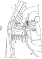
- FIG. 4 is a perspective view showing an example lock mechanism 80 for the engine hood 11.
- the lock mechanism 80 has a function of holding the engine hood 11 in a state of housing the engine E and the like placed on the machine body (on the chassis 12).
- the lock mechanism 80 is provided inside the engine hood 11, on one side of the front-rear direction of the machine body. Since the present embodiment deals with a case where the front side of the engine hood 11 opens, the lock mechanism 80 is also positioned on the front side.
- the lock mechanism 80 includes: a lock bar 81, a fitting member 82, a lock catch 83, and pop-up springs 84, 84 as elastic members.
- a wire 85 serving as a dynamic force transmission member is connected to the lock mechanism 80.
- the wire 85 is structured by a linearly extending metal wire, whose outer circumference is covered by a cylindrical hollow outer wire made of a spiral-shaped steel wire, vinyl, and the like.
- the lock bar 81 may be attached to any one of the machine body and the engine hood 11.
- the lock bar 81 is attached to the engine hood 11.
- the rod-like lock bar 81 is bent to have a substantially U-shape as viewed from a side, and portions on both ends thereof extended in the front-rear directions are fixed to the engine hood 11 by welding and the like.
- the bent lower end of the U-shape extends substantially horizontally in the front-rear direction when the engine hood 11 is closed.
- the fitting member 82 may be attached to any one of the machine body and the engine hood 11.
- the fitting member 82 is attached to the machine body.
- the fitting member 82 is fixed by a bolt and the like to an upper portion of a front frame 86 in a substantially gate-like shape as viewed from the front, for attaching the above-mentioned radiator 72 on the back surface side.
- the fitting member 82 is a flat plate formed in a substantially M-shape as viewed from the front.
- the fitting member 82 extended in the up-down direction in a flat-plate form is perpendicular to the lock bar 81 which extends substantially horizontally in the front-rear direction.
- the fitting member 82 has a notch 87 that serve as a fitting portion for the lock bar 81 (see later mentioned FIG. 5 ). More specifically, the notch 87 in a substantially U-shape extends downward from a middle portion of the substantially M-shape as viewed from the front (i.e., relative to the left/right direction) of the fitting member 82.
- the width of the notch 87 as viewed from the front has a dimension that is equal to or greater than the diameter of the lock bar 81.
- the fitting member 82 has a spring attaching portion 88 below the lower end of the notch 87.
- the spring attaching portions 88 exemplified in FIG. 4 protrudes forward from the left end (right end as viewed from the front) and has a hole perforated in the left/right direction.
- the lock catch 83 may be attached to any one of the machine body and the engine hood 11.
- the lock catch 83 is attached to the machine body.
- the lock catch 83 is a flat plate which overlaps the front surface of the fitting member 82.
- the lock catch 83 has an N-like-shape turned 90 degrees, as viewed from the front; however, the shape of the lock catch 83 is not limited to this.
- FIG. 5 is a front elevational view showing an example state in which the lock catch 83 of the lock mechanism 80 is not rotated.
- FIG. 6 is a front elevational view showing an example state in which the lock catch 83 of the lock mechanism 80 is rotated.
- the lock catch 83 is provided in such a manner that its back surface is able to rotate in directions it slides with respect to the front surface of the fitting member 82. Therefore, a through hole is formed at the lower portions of the fitting member 82 and the lock catch 83, and for example, the lock catch 83 is attached to the fitting member 82 and made rotatable by a rotating pin 89.
- the lock catch 83 has the wire 85 attached in a position opposite to the spring attaching portion 88 of the fitting member 82, relative to the left and right directions.
- the lock catch 83 is structured to be rotatable about the rotating pin 89 as the axis, when the wire 85 is pulled (see FIG. 6 ). More specifically, a hole is formed on the right end (left end as viewed from the front) of the lock catch 83 exemplified in FIG. 4 and the like. To that hole of the lock catch 83 and a hole at a leading end part of the wire 85 (wire terminal) formed in a ring-shape, a hinge pin 90 is inserted and is retained by a split pin 91.
- the lock catch 83 has a spring attaching portion 92 in a position opposite to the spring attaching portion 88 of the fitting member 82, relative to the left and right directions, but substantially the same relative to the up-down direction.
- the spring attaching portions 92 exemplified in FIG. 4 and the like protrudes forward from the right end (left end as viewed from the front) and has a hole perforated in the left/right direction. Between the hole on the spring attaching portion 88 and the hole on the spring attaching portion 92, a spring 93 is attached. The spring 93 biases the lock catch 83 in a direction of pulling the wire 85.
- the type of the spring 93 is not particularly limited provided that it can bias the lock catch 83. In the example of FIG. 4 , a pull coil spring is used.
- the lock catch 83 has a notch 94 in a substantially C-shape which extends horizontally relative to a left/right direction, towards the side where the wire 85 is attached.
- the lower end of the notch 94 is substantially the same as or slightly lower than the lower end of the notch 87 of the fitting member 82. That is, the notch 94 is formed so as to correspond to the notch 87, matching with the portion of the fitting member 82 where the lock bar 81 is fit as viewed from the front.
- the width of the notch 94 as viewed from the front is larger than the diameter of the lock bar 81.
- the lock catch 83 has a hook portion 95 that rotates according to movement of the wire 85. More specifically, the hook portion 95 is formed above the notch 94, from the side of attaching the wire 85 towards opposite direction relative to the left and right directions.
- a through hole is formed as viewed from the front by the notch 87 of the fitting member 82 and the notch 94 of the lock catch 83. This through hole is the position where the lock bar 81 fits in. The lock bar 81 in the through hole is locked by the hook portion 95 (see FIG. 5 ).
- the hook portion 95 is structured so as to rotate against the biasing force of the spring 93, when the lock bar 81 is pressed in from the above.
- the hook portion 95 has its upper side declined downward towards the protruding end, as viewed from the front.
- the hook portion 95 may have a structure such that its lower side extends substantially horizontally, and its upper side is tilted downward towards the protruding end. Further, the protruding end connecting the upper side and the lower side is preferably chamfered so the lock bar 81 of the hook portion 95 smoothly slide.
- the pop-up springs 84, 84 are attached between the machine body and the engine hood 11 biases the engine hood 11 in the direction of opening.
- the pop-up springs 84, 84 may have a biasing force that lifts the lock bar 81 above the hook portion 95, while the lock bar 81 is not locked by the hook portion 95.
- the pop-up springs 84, 84 may be attached either one of the machine body and the engine hood 11; however, the pop-up springs 84, 84 are attached to the machine body in the example of FIG. 4 .
- the pop-up springs 84, 84 are attached to the upper end of the front frame 86, aligned in the left/right direction.
- the pop-up springs 84, 84 are each structured by, for example, a compression coil spring and are arranged for biasing in the up-down directions.
- the pop-up springs 84, 84 are preferably arranged symmetrically on left and right, in terms of balancing at opening and closing of the engine hood 11 and restraining rattling of the engine hood 11. It should be noted that, in cases where a pop-up spring 84 is also arranged in the middle relative to the left/right directions, the number of pop-up springs 84, 84 may be an odd number.
- the hook portion 95 moves against the biasing force of the spring 93 according to the movement of the wire 85. Then, the biasing force of the pop-up springs 84, 84 lifts the lock bar 81 above the hook portion 95 (see FIG. 6 ). This way, the engine hood 11 is also lifted by a predetermined amount that allows, for example, inserting of a hand of a worker between the machine body and the engine hood 11. From this state, the engine hood 11 is opened by the worker. Since the gas springs 76, 76 (see FIG. 3 ) are attached between the machine body and the engine hood 11, the engine hood 11 can be opened and closed with a light force, and the engine hood 11 can be stopped at any open angle.
- the lock mechanism 80 of the tractor 10 is structured so as to lock the engine hood 11, while the engine hood 11 is closed against the biasing force of the pop-up springs 84, 84 and the lock bar 81 is positioned below the hook portion 95. Further, the lock mechanism 80 of the tractor 10 is structured so that the engine hood 11 is openable while the lock bar 81 is positioned above the hook portion 95. Therefore, it is possible to provide a tractor 10 having the lock mechanism 80 of the engine hood 11 which is excellent in workability.
- FIG. 7 is a side view showing an example overview of a structure of the engine E and the DPF 100 inside an engine hood 11.
- the engine E includes a cylinder block 152 having therein a crank shaft 151 (output shaft) and a plurality of pistons.
- the crank shaft 151 extends in the front-back direction of the engine E, and is rotatably attached to the cylinder block 152. Both front and rear ends of the crank shaft 151 protrude from front and rear ends of the cylinder block 152, respectively.
- the engine E is placed on the chassis 12 (see FIG. 1 ) so that the crank shaft 151 extends in the front-rear direction of the tractor 10.
- a cylinder head 153 is mounted with a not-shown head gasket therebetween.
- the above-mentioned intake manifold 78 is arranged on the right side surface of the cylinder head 153 (see FIG. 3 ).
- an exhaust manifold 154 is arranged on the left side surface of the cylinder head 153. Therefore, the exhaust manifold 154 and the intake manifold 78 are arranged on left and right side surfaces of the engine E, respectively. It should be noted that the top surface of the cylinder head 153 is covered by a cylinder head cover 155.
- the cooling fan 156 is provided on the front surface side of the cylinder block 152.
- a crank shaft pulley 157 and a cooling fan pulley 158 are attached to the crank shaft 151 and the rotation shaft of the cooling fan 156, respectively.
- a cooling fan V-belt 159 for transmitting a drive force of the crank shaft 151 is provided. This way, the rotational drive force is transmitted to the cooling fan 156.
- external air taken into inside of the engine hood 11 through the front grill 70 by the cooling fan 156 passes the radiator 72, and is then fed to the engine E and the DPF 100 behind.
- the exhaust manifold 154 collects exhaust gas generated in each cylinder of the engine E.
- An exhaust passage of the engine E is structured so as to introduced the exhaust gas having passed the exhaust manifold 154 into the DPF 100.
- turbo supercharger is structured so that its turbine on the side of the exhaust passage is rotated by the exhaust gas, and for example a centrifugal compressor is driven with the rotational force to compress the air on the side of the intake passage.
- the EGR device connects the exhaust manifold 154 and the intake manifold 78 via an EGR cooler for cooling the exhaust gas, and includes a valve for adjusting the amount of exhaust gas supplied. In a structure including these members, the exhaust gas having passed the exhaust manifold 154 is branched into any of the DPF 100 and intake manifold 78, through the side of the exhaust passage of the turbo supercharger and the EGR device.
- a purification inlet port pipe 101 connected to the exhaust downstream side of the exhaust manifold 154 is connected to the DPF 100. Exhaust gas from each cylinder of the engine E is emitted outside, via the DPF 100 through the exhaust pipe 102 connected to the outlet side of the DPF 100.
- the DPF 100 filters and collects particulate matter (PM) such as sooth (hydrocarbon) contained in the exhaust gas, and purifies the exhaust gas by burning and removing the collected particulate matter, with a use of an oxidation catalyst.
- PM particulate matter
- the DPF 100 has a substantially cylindrical shape, and is made of a refractory metal.
- the DPF 100 is attached to the top of the engine E so that its axial direction is parallel to the crank shaft 151 of the engine E.
- the DPF 100 has a structure such that a substantially cylindrical filter case accommodated therein via an insulating material such as glass wool, and for example, a diesel oxidation catalyst 103 of platinum and the like, and a soot filter 104 are serially aligned in this order from the upstream side of the flow direction of the exhaust gas, in the filter case.
- the exhaust gas flows from the rear side to the front side of the tractor 10 in the DPF 100.
- the small space in the engine hood 11 can be efficiently used.
- the DPF 100 is attached on the side of the exhaust manifold 154 relative to the left/right direction of the engine E.
- high temperature exhaust gas can be always introduced to the DPF 100, and a good exhaust gas purification performance can be maintained.
- the diesel oxidation catalyst 103 acts on the nitrogen monoxide (NO) contained in the exhaust gas and oxides the same to unstable nitrogen dioxide (NO 2 ), when the temperature of the exhaust gas exceeds a renewable temperature (e.g., approximately 300 degrees).
- the soot filter 104 has a honeycomb structure having a plurality of cells partitioned by a porous partition walls capable of filtering particulate matters. It should be noted that the DPF 100 may have a structure in which the soot filter 104 itself holds an oxidation catalyst.
- the particulate matter is deposited on the soot filter 104. It should be noted that the status of deposition of the particulate matter is detectable based on a differential pressure between the upstream and downstream of the soot filter 104.
- the soot filter 104 is renewed and the performance of the soot filter 104 for collecting the particulate matter is recovered. Therefore, the DPF 100 becomes a very high temperature, because high-temperature exhaust gas is introduced to the soot filter 104 or the soot filter 104 itself is heated for renewing the soot filter 104. Further, the DPF 100 becomes a high temperature, also when the particulate matter deposited on the soot filter 104 is rapidly burned.
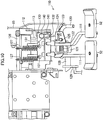
- FIG. 8 is a plan view showing an example overview of a structure inside the engine hood 11.
- the high-temperature DPF 100 that could be a thermal resource, in particular, is above the engine E and is accommodated in the engine hood 11, on slightly left or right side of the machine body.
- the DPF 100 exemplified in FIG. 8 is arranged on the left side of the tractor 10, in such a manner that its cylindrical axis extends in the front-rear direction.
- the air intake pipe 73 and the air cleaner 74 are arranged in such a manner as to avoid the middle of the tractor 10 relative to the left/right direction. Further, as hereinabove mentioned, the upper portion of the air intake pipe 73 is formed to be substantially flush with the upper portion of the shroud 71. With the arrangement, the tractor 10 houses the parts efficiently in a small space, with a particularly small width relative to the left/right direction, and prevents a shape of the engine hood 11 with an upwardly protruding middle relative to the left/right direction. This provides broader visibility from the driver sheet 20 particularly in the direction towards the ground, and improves the operability while driving.
- the wire 85 connected to the lock catch 83 of the above-mentioned lock mechanism 80 is arranged on the opposite side to the DPF 100 relative to the left and right of the machine body.
- the wire 85 is arranged on the right side which is the opposite side to the DPF 100 arranged on the left side, in the area of the engine hood 11.
- the wire 85 is stretched from the lock catch 83 positioned in the front portion of the engine hood 11 to the right end of the area of the engine hood 11 along the front frame 86. From there, the wire 85 is stretched to the rear end of the area of the engine hood 11 along the right end of the area of the engine hood 11. In the upper portion at the right end of the shroud 71, there may be formed a through hole in the front-rear direction, and the wire 85 may pass through this through hole.
- the wire 85 is stretched along the right end in such a manner as to be distanced as much as possible from the DPF 100 on the left side of the machine body. This keeps the wire 85 hardly affected by the DPF 100 that generates a very high temperature, and avoids unnecessary deterioration of the durability. It should be noted that the wire 85 is introduced to a position nearby the brake pedal device in the cabin 19, from the rear end of the area of the engine hood 11.
- FIG. 9 is side view showing an example overview of a connection structure of the brake pedal device 110.
- the brake pedal device 110 is for performing braking operation to an axle of the rear wheels 14, 14 (see FIG. 1 ).
- the tractor 10 is structured so that a braking device inside a not-shown rear axle casing activates, when the brake pedal device 110 is operated.
- Left and right brake pedals 52, 52 constituting the brake pedal device 110 are linked to left and right braking devices, respectively.
- the connection structure of the left side and the right side of the left and right brake pedal 52, 52 are the same as viewed from a side. Therefore, the following collectively details the left and right brake pedals 52, 52, as a connection structure of the brake pedal device 110.
- the tractor 10 has the brake pedal device 110 for activating and deactivating the braking device, below the dashboard 16 on the front side of the cabin 19.
- the brake pedal device 110 has an arm (brake arm 111) extended below the dashboard 16 in such a manner as to bend rearward of the machine body, which rotates with respect to the machine body.
- the brake arm 111 has its one end attached to the rotation shaft 112 extended in the left/right direction within the area of the dashboard 16, and is structured to be rotatable in the front-rear direction of the machine body, with the rotation shaft 112 as the fulcrum.
- the other end of the brake arm 111 is provided with the brake pedal 52 to be stepped on by an operator.
- the tractor 10 is structured so that the stepping on the brake pedal 52 rotates the brake arm 111.
- a plate 113 extended forward of the machine body is fixed on the one end of the brake arm 111.
- the plate 113 is structured to rotate with rotation of the brake arm 111.
- the front end of the plate 113 is rotatably connected to an upper end of a longitudinal connecting rod 114 which penetrates the floor surface of the cabin 19 and extends in the up-down direction below the floor surface.
- the connection structure of the plate 113 and the longitudinal connecting rod 114 is for converting the rotation of the brake arm 111 in the front-rear directions into the rotation in the up-down directions.
- an L-shaped link 115 bend in a shape of L is rotatably connected.
- an L-shaped link support portion 117 is fixed which rotatably supports a middle portion of the L-shaped link 115 as a link rotation shaft 116.
- Another end of the L-shaped link 115 is rotatably connected to the front end of a horizontal connecting rod 118 extended in the front-rear directions.
- a brake operating lever 119 To the rear end of the horizontal connecting rod 118, the leading end of a brake operating lever 119 is rotatably connected.
- the brake operating lever 119 is provided to the transmission case TM, and is structured to rotate for activating and deactivating the braking device.
- the braking device activates when the brake pedal 52 is stepped on.
- FIG. 10 is a front elevational view showing an example of the brake pedal device 110.
- FIG. 11 is a side view showing the example of the brake pedal device 110. It should be noted that, in this example, a view point from a side of the driver sheet 20 (see FIG. 2 ) is referred to as the front surface.
- the brake arm 111 to which the brake pedal 52 is attached to its leading end is structured to be rotatable in the front-rear directions (a side far from the viewer in a direction from the viewer towards the sheet of FIG. 10 (hereinafter, viewer's far side) and a side close to the viewer (hereinafter, viewer side)) with the rotation shaft 112 as the fulcrum.
- the left and right brake arms 111, 111 there is a hole penetrating in the left/right direction. Through this hole, a connecting rod 120 serving as a connection member connecting the left and right brake arms 111, 111 is detachably provided.
- the connecting rod 120 is inserted while traveling, and is pulled out during work.
- the connecting rod 120 exemplified in FIG. 10 and the like has one end side inserted from the side of the right brake arm 111 to the left brake arm 111, and the other end side is bent downwards, and toward the rear side (viewer side on FIG. 10 ) where the driver sheet 20 (see FIG. 2 ) is provided.
- the bent portion on the other end of the connecting rod 120 serves as a holding part which contributes to a good operability.
- a spring storage strut 121 is attached which has a substantially C-shape towards the side of the left brake arm 111 with portions above and below the position of inserting the connecting rod 120 as the base points.
- a compression coil spring 122 is attached on the outer circumference of a portion of the connecting rod 120, which portion is between the right brake arm 111 and the spring storage strut 121 while the left and right brake arms 111, 111 are linked by the connecting rod 120. In this state, the connecting rod 120 is biased towards the side of the left brake arm 111 by the compression coil spring 122.
- a connecting rod guide plate 123 is attached to this connecting rod guide plate 123.
- a guide groove 124 in a substantially J-shape as viewed from the front is formed to this connecting rod 120.
- a guide pin 125 to be inserted into the guide groove 124 is attached to the connecting rod 120. While the connecting rod 120 is pulled out to the right side in the above structure, rotating the holding part upward (towards viewer side on FIG. 10 ) links the left and right brake pedal devices 110. Rotating the holding part downward (towards viewer's far side on FIG. 10 ) release the link of the left and right brake pedal device 110.
- a spring attaching strut 126 extended in left/right direction is provided above the rotation shaft 112. Between the spring attaching strut 126 and the left and right brake arms 111, 111, tension coil springs 127, 127 which bias the left and right brake arms 111, 111 rearward (viewer side on FIG. 10 ) are attached. When the operator stops stepping in the brake pedal 52, in the structure, the brake arm 111 rotates (returns) rearwards.
- a brake fixing strut 128 extended towards left is attached.
- a brake arm stopping member 129 which engages with the brake fixing strut 128 is provided in a position along a rotation track of the brake fixing strut 128.
- the brake arm stopping member 129 has a plurality of saw-teeth-like protrusions and dents in a position where the brake fixing strut 128 is engaged when the left brake arm 111 rotates a predetermined angle or more.
- the brake pedal device 110 is structured so that, when the left brake pedal 52 is stepped in by a predetermined amount, the brake fixing strut 128 and the protrusions and dents of the brake arm stopping member 129 engage with each other, thus maintaining the state where the left brake pedal 52 is stepped in.
- the brake pedal device 110 is structured so as to allow a state in which a parking brake that maintains the braked-state of the tractor 10 is made active, by the brake fixing strut 128 and the brake arm stopping member 129.
- the brake arm stopping member 129 does not have the protrusions and dents in its position to meet the brake fixing strut 128, when the left brake pedal 52 is further stepped in from the state where the parking brake is functioning. Therefore, the brake pedal device 110 has a structure such that, when the left brake pedal 52 is again stepped in from the state where the parking brake is functioning, the engagement of the brake fixing strut 128 with the protrusions and dents on the brake arm stopping member 129 is released.
- the tension coil spring 127 is attached to the left brake arm 111.
- the brake pedal device 110 has a structure such that, when the left brake pedal 52 is again stepped in from the state where the parking brake is functioning, the brake arm 111 rotates rearward (to the viewer side on FIG. 10 ) thus releasing the parking brake.
- the tractor 10 is structured so that the parking brake is maintained in an active state by the stepping-in operation of one brake pedal device 110 out of a pair of left and right brake pedal devices 110.
- the structure of activating and deactivating the parking brake is provided to the left brake pedal 52.
- the tractor 10 has a structure such that the left and right brake pedal devices 110 are linked by a connecting rod 120. Therefore, while the left and right brake pedal devices 110 are linked, the parking brake is maintained active not only by the stepping-in operation of the left brake pedal 52, but also by a stepping-in operation of the right brake pedal 52.
- a brake detection switch attaching strut 130 extended in the left/right direction is provided on the rear side (viewer side on FIG. 10 ) of the left and right brake arms 111, 111.
- the brake detection switch attaching strut 130 is parallel to the brake arm 111 in the state of being rotated rearward (towards viewer side on FIG. 10 ).
- the brake detection switch attaching strut 130 is provided, in that space, with left and right brake detection switches 131, 131 configured to detect contact of the left and right brake arms 111, 111, respectively.
- the left and right brake detection switches 131, 131 are configured to detect whether or not the left and right brake pedals 52, 52 are stepped in, respectively.
- the brake detection switch attaching strut 130 as viewed from the front, is provided with a notch 132 in a position that does not overlap the left and right brake arms 111, 111.
- the notch 132 as viewed from the front, which is exemplified in FIG. 10 , is positioned on the right side, and below the left and right brake detection switches 131, 131.
- the notch 132 is formed in a substantially U-shape, and is notched upward from the lower end of the brake detection switch attaching strut 130.
- an operation lever 140 constituting an operation unit for releasing the lock of the lock mechanism 80 is attached. That is, the tractor 10 is structured so that, between the lock mechanism 80 and the operation lever 140, the wire 85 transmits an operation of the operation lever 140 to the lock mechanism 80.
- the outer wire 141 of the wire 85 introduced from the rear end of the area of the engine hood 11 into the cabin 19 is fixed to the notch 132.
- the inner wire of the wire 85 is connected to the operation lever 140.
- the operation lever 140 is attached so as to extend rearward from the brake detection switch attaching strut 130 (see FIG. 11 ). Further, the operation lever 140 can be pulled rearward.
- the position of attaching the operation lever 140 is preferably a position that does not hinder other work and yet provides a good operability.
- the operation lever 140 is pulled rearward by the operator.
- the operation of the operation lever 140 is transmitted by the wire 85 to the lock catch 83 of the lock mechanism 80.
- the lock catch 83 rotates, and the lock bar 81 locked by the hook portion 95 is lifted above the hook portion 95 by the biasing force exerted by the pop-up springs 84, 84.
- the engine hood 11 is lifted by the above operation. It should be noted that, the operation of the operation lever 140 by a hand does not fully open the engine hood 11. After the above operation, the engine hood 11 is opened by the operator.
- FIG. 12 is a perspective view of the tractor 10 showing an example arrangement of the wire 85.
- FIG. 12 omits illustration of the engine hood 11 and the cabin 19.
- the operation lever 140 for operating the lock mechanism 80 of the engine hood 11 is arranged in the cabin 19.
- This structure meets the regulation for obtaining homologation in Europe. That is, the tractor 10 can eliminate a need for a key or a cover as a further releasing mechanism requiring another tool, for the operating lever 140. Further, the tractor 10 can reduce the number of parts. Further, the tractor 10 allows a one-touch operation for releasing the lock mechanism 80, which is favorable in terms of operability.
- the wire 85 connecting the lock mechanism 80 and the operation lever 140 is arranged on the opposite side of the DPF 100 which is a high-heat source.
- This structure can reduce an influence of the heat to the wire 85.
- the wire 85 in the engine hood 11 may be fixed by a clamp 143 and the like to a fix plate 142 having a rectangular shape as viewed from a side, which is on the right side of the engine E and which is for fixing a fuel hose, and a hose of an air conditioner.
- FIG. 13 is a plan view showing an overview of structure inside an engine hood 11 related to a modification of the tractor 10.
- the DPF 100 is arranged on the right side in the engine hood 11.
- the wire 85 may be arranged on the left side.
- the wire 85 in this case is introduced from the rear end of the area of the engine hood 11 into the cabin 19, nearby a clutch pedal 53.
- the wire 85 may be attached to a clutch detection switch attaching strut, in a similar manner to the above-mentioned embodiment.
- the present embodiment provides a tractor 10 including an engine hood 11 configured to be openable and closable with respect to a machine body, which covers and houses a DPF 100 on one side of the machine body relative to a left/right direction, and a cabin 19 positioned rearward of the engine hood 11, including: a lock mechanism 80 configured to lock the engine hood 11; an operation lever 140 configured to unlock the lock mechanism 80; and a wire 85 configured to transmit operation of the operation lever 140 to the lock mechanism 80, between the lock mechanism 80 and the operation lever 140, wherein the lock mechanism 80 is disposed in the engine hood 11, on one side of the front-rear direction of the machine body, and the operation lever 140 is disposed in the cabin 19.
- FIG. 14 is a side view showing an example brake pedal device 210 related to the other embodiment.
- the tractor 10 of the other embodiment is different in the position of attaching the operation lever 140. It should be noted that structures identical to the above-mentioned embodiment are given the same reference symbols, and description for the structures is omitted as needed.
- an operation lever attaching strut 211 extended towards right is attached.
- a notch 212 is formed from the right end of the operation lever attaching strut 211 towards left.
- the operation lever 140 constituting the operation unit for unlocking the lock mechanism 80 is attached to this notch 212
- the operation lever 140 attached to the right brake arm 111 rotates along with rotation of the right brake arm 111.
- the brake pedal device 210 includes a pair of left and right brake pedal devices 210, 210 associated with the left and right brake devices, and further includes a connecting rod 120 (see FIG. 10 and the like) which links the pair of left and right brake pedal devices 210, 210.
- the parking brake is in turned active by a stepping-in operation of the brake pedal device 210, while the pair of left and right brake pedal devices 210, 210 are linked together through the connecting rod 120.
- the tractor 10 of the other embodiment is structured so that the operation lever 140 is operable when the braking device is operated and the parking brake is active, and when the parking brake is deactivated, the operation lever 140 is not operable.
- FIG. 15 is a side view showing a state where the brake pedal device 210 related to the other embodiment is rotated.
- FIG. 15 shows the position of the brake arm 111 while the parking brake is active.
- FIG. 15 ( FIG. 14 ) further shows the lines 220 and 221 of the dashboard 16 on the side of the driver sheet 20 (on the rear side).
- the front-rear direction is segmented at the rectilinear line 220 of the dashboard 16 extended from the above to downward and tilted forward.
- the dashboard 16 segments the left/right direction, and the up-down direction of the line 221 is opened.
- the operation lever 140 is above the line 221 of the dashboard 16, during the state where the parking brake is inactive. Further, the operation lever 140 and the line 220 of the dashboard 16 are close to each other. Therefore, even if the operator tries to pull the operation lever 140, the dashboard 16 at the line 220 gets in the way, disabling the operation. That is, while the parking brake is inactive, the operation area for the operation lever 140 is vanished, thus causing an inoperable state.
- the operation lever 140 is below the line 221 of the dashboard 16, during the state where the parking brake is active.
- the operation lever 140 and the line 220 of the dashboard 16 are distanced from each other. Therefore, when the operation lever 140 is pulled, the dashboard 16 at the line 220 does not get in the way of the operation. That is, while the parking brake is active, the operation area for the operation lever 140 is ensured, thus causing an operable state.
- an operable state and an inoperable state of the operation lever 140 can be physically switched, and mistakes in operation can be prevented.
- a tractor 10 having a lock mechanism 80 for the engine hood 11, which is further excellent in workability in a situation requiring unlocking.
- the operable state and the inoperable state in other viewpoints mean the operation lever 140 being in a position blocked by the dashboard 16 when the parking brake is inactive, and in a position exposed from the dashboard 16 when the parking brake is active.
- the operation lever 140 when the parking brake is inactive, the operation lever 140 is above the line 221 of the dashboard 16 (see FIG. 14 ). Further, when viewed from the driver sheet 20, the operation lever 140 is positioned on a side over the line 220 of the dashboard 16. Therefore, the operating lever 140 is positioned at the blind spot from the driver sheet 20. That is, while the parking brake is inactive, the operation lever 140 is in a position to be blocked by the dashboard 16, and in the inoperable state.
- the operation lever 140 is below the line 221 of the dashboard 16, during the state where the parking brake is active (see FIG. 15 ). Further, when viewed from the driver sheet 20, the operation lever 140 is positioned on a side over the line 220 of the dashboard 16. Therefore, while the parking brake is active, the operation lever 140 is in a position exposed from the dashboard 16, and is in the operable state. With the above structure, an operable state and an inoperable state of the operation lever 140 can be visually switched, and mistakes in operation can be prevented. Thus, there is provided a tractor 10 having a lock mechanism 80 for the engine hood 11, which is further excellent in workability in a situation requiring unlocking.
- the tractor 10 of the other embodiment is structured so that the parking brake is maintained in an active state by the stepping-in operation of one of a pair of left and right brake pedal devices 210, 210, for example, the left brake pedal device 210.
- the operation lever 140 is attached to the brake arm 111 of the other brake pedal device 210, for example, to the right brake pedal device 210. Therefore, while the left and right brake pedal devices 210, 210 are not linked to each other, the operation lever 140 attached to the right brake pedal device 210 does not move even if the step-in operation is performed on the left brake pedal device 210, turning the parking brake active.
- the operable state of the operation lever 140 is prevented while the left and right brake pedal devices 210, 210 are not linked to each other, and mistakes in operation can be prevented.
- the operation lever 140 is not brought into the operable state unless the tractor 10 is fully stopped and the parking brakes on the left and right are both active. Therefore, the lock bar 81 will not be lifted above the hook portion 95 while the tractor 10 is running.
- a tractor 10 having a lock mechanism 80 for the engine hood 11, which is further excellent in workability in a situation requiring unlocking.
- the other embodiment provides a tractor 10 including an engine hood 11 configured to be openable and closable with respect to a machine body, and a cabin 19 behind the engine hood 11, including: a lock mechanism 80 configured to lock the engine hood 11; an operation lever 140 configured to unlock the lock mechanism 80; and a wire 85 configured to transmit operation of the operation lever 140 to the lock mechanism 80, between the lock mechanism 80 and the operation lever 140, wherein the lock mechanism 80 is disposed in the engine hood 11, on one side of the front-rear direction of the machine body, the operation lever 140 is disposed in the cabin 19, a dashboard 16 is disposed in a front portion of the cabin 19, a brake pedal device 210 for activating and deactivating a braking device is disposed below the dashboard 16, the operation lever 140 is brought into an operable state when the braking device is operated and a parking brake is active, and the operation lever 140 is brought into an inoperable state when the parking brake is inactive. Therefore, mistakes in operation can be prevented.
- a tractor 10 having a
- operation lever 140 may not be attached to the brake pedal device 210, and may be attached to, for example, a dashboard 16 and may be structured to be operable state when the parking brake is active.
- FIG. 16 is a side view showing a modification of the braking device related to the other embodiment.
- another dynamic force transmission member is provided between a brake pedal device 310 and a hand brake device 300.
- the hand brake lever 62 structuring the hand brake device 300 is formed in a rod-like shape extended in the front-rear direction on the right side of the arm-rest 56 (see FIG. 2 ).
- the hand brake lever 62 is provided so as to rotate in the up-down directions with it rear side as the axis.
- the hand brake lever 62 is structured so as to lift by being pulled upward, and pushed down by being pressed downward while a button 301 at the front end of the hand brake lever 62 is pressed.
- the tractor 10 has a structure such that an operation of the hand brake lever 62 is transmitted to another braking device by a link mechanism 302 such as wire.
- a link mechanism 302 such as wire.
- leading ends of left and right hand brake operation levers 303, 303 are rotatably connected.
- the hand brake operation levers 303, 303 are structured so their rotation activates and deactivates the other braking devices.
- the parking brake is turned active when the hand brake lever 62 is lifted, and the parking brake is turned inactive when the hand brake lever 62 is pushed down.
- a wire 311 serving as the other dynamic force transmission member is provided between the brake pedal device 310 and the hand brake operation lever 303 structuring the hand brake device 300. It should be noted that the brake pedal device 310 is positioned on the right side of the machine body, the wire 311 is preferably provided between the hand brake operation lever 303 on the right side and the brake pedal device 310.
- an axle side wire attaching strut 312 having a notch is provided in front of the right side hand brake operation lever 303, and one end 313a of an outer wire 313 of the wire 311 is fixed. To the right side hand brake operation lever 303, one end 314a of an inner wire 314 of the wire 311 is fixed.
- a pedal side wire attaching strut 315 having a notch is provided in front of the right brake arm 111 of the brake pedal device 310, and the other end 313b of the outer wire 313 of the wire 311 is fixed.
- a notch 317 different from the above-mentioned notch 212 is formed.
- the other end 314b of the inner wire 314 of the wire 311 is fixed.
- the modification of the tractor 10 related to the other embodiment is structured so that the brake pedal device 310 operates in association with an operation of activating and deactivating another braking device by the hand brake lever 62.
- the modification of the tractor 10 of the other embodiment is also structured so that the operation lever 140 is in the operable state when the braking device is operated and the parking brake is active, and when the parking brake is deactivated, the operation lever 140 is in the inoperable state.
- the operable state and the inoperable state of the operation lever 140 can be switched by two systems of the brake pedal device 310 and the hand brake device 300, and hence mistakes in operation can be prevented.
- a tractor 10 having a lock mechanism 80 for the engine hood 11, which is further excellent in workability in a situation requiring unlocking.
- a working vehicle disclosed herein is not limited to a tractor 10, and is suitably applicable to working vehicles such as transplanting machines and construction machine, which has an engine hood 11, a DPF 100, and a brake pedal device 110 (210, 310), particularly left and right brake pedal devices 110, 110 (210, 210, 310, 310).
Landscapes
- Engineering & Computer Science (AREA)
- Transportation (AREA)
- Mechanical Engineering (AREA)
- Chemical & Material Sciences (AREA)
- Combustion & Propulsion (AREA)
- Superstructure Of Vehicle (AREA)
Abstract
Description
- The present invention relates to a working vehicle having an engine hood, and more specifically, relates to a lock mechanism of the engine hood.
- In a working vehicle exemplified by a tractor, an engine and the like are placed in a front portion of its machine body, and there is an engine hood configured to open or close to cover them. In a front portion of the engine hood for example, a lock mechanism configured to keep the engine hood closed is provided.
- Patent Literature 1 (hereinafter, PTL 1) discloses a hood locking device for a tractor, which is described as follows. Namely, an engine hood is formed by: an engine hood main body whose upper-rear portion is pivotally supported with respect to a vehicle body in such a manner as to open/close; and an engine hood lower-front portion positioned in a lower-front of the engine hood main body and fixed to the vehicle body. The lower-front portion of the engine hood main body is made lockable to the front portion of the vehicle body by locking means. To the front portion of the vehicle body, a lock stay is provided behind the engine hood lower-front portion. Above the lock stay, there is provided a lock member which pivots to disengageably engage with an engagement tool provided in the lower-front portion of the engine hood. There is provided an unlocking member which operates to pivot the lock member through a back-and-forth movement. A front portion of this unlocking member penetrates, and protrude from, the lower-front portion of the engine hood.
- Meanwhile, efforts to reduce the burden on the global environment are regarded as an urgent task. Tractors are no exceptions, and emission constraint is gradually strengthened throughout the world. Under such a circumstance, tractors with an exhaust processing device configured to purify exhaust gas are introduced one after another. More specifically, to remove particles containing harmful substances in exhaust gas generated in the diesel engine, a Diesel Particulate Filter (DPF) is attached. The DPF traps the particles by a filter. However, continuing the trap of the exhaust gas causes clogging of the filter, leading to a drop in its function. To address this issue, the particles deposited on the filter are removed to restore the filter. As one of the methods for restoring the filter, there is one which increases the temperature of the filter to burn the particles deposited. In this case, the temperature of the filter reaches several hundred degrees, and is extremely high-temperature.
- Patent Literature 2 (hereinafter, PTL 2) discloses a diesel engine built-in and accommodated in an engine room of a working vehicle and the like, in which a muffler connecting to this engine is positioned close to the upper side of an engine main body, and an oxidation catalyst and a diesel particulate filter, or only the diesel particulate filter is/are provided inside the muffler.
-
- PTL1: Japanese Patent Application Laid-Open No.
H08-026140 (1996 - PTL 2: Japanese Patent Application Laid-Open No.
2008-031955 - In cases of the hood locking device of the tractor in
PTL 1, unlocking is troublesome because a worker needs to get off the driver seat and go around to the front of the engine hood. Therefore, improvement in workability at a time of unlocking is desired. It should be noted that, in Europe too, to obtain a certificate for selling agricultural vehicles, i.e., a regulation for having them homologated, it is advised that another cover serving as a releasing mechanism requiring key or a different tool be attached to the unlocking member disclosed inPTL 1. Further, in the structure of the diesel engine of PTL 2, an extremely high temperature diesel particulate filter is installed in the engine hood between the hood lock mechanism and the driving unit such as a cabin. In such a structure, there is a need for considering the path from the lock mechanism to the unlocking member and the position of attaching the unlocking member on the floor or in the cabin and the like. - As to the unlocking member on the other hand, it is sufficient if it is available in situations requiring the operation.
- In view of the above, it is an object of the present invention to provide a working vehicle having an engine hood lock mechanism excellent in its workability, in situations where unlocking is required.
- To achieve the above problems, the present invention is a working vehicle including an engine hood configured to be openable and closable with respect to a machine body, and a driving unit behind the engine hood, including: a lock mechanism configured to lock the engine hood; an operation unit configured to unlock the lock mechanism; and a dynamic force transmission member configured to transmit operation of the operation unit to the lock mechanism, between the lock mechanism and the operation unit, wherein the lock mechanism is disposed in the engine hood, on one side of the front-rear direction of the machine body, and the operation unit is in the driving unit.
- Further, the working vehicle may include a dashboard on a front side of the driving unit, wherein the operation unit is provided below the dashboard.
- Further, the working vehicle may include: a dashboard on a front side of the driving unit; and brake pedal devices below the dashboard, which devices are configured to activate and deactivate braking devices, wherein the operation unit is in an operable state, when the braking devices are operated, and a parking brake is active, and the operation unit is in an inoperable state when the parking brake is inactive.
- Further, the brake pedal devices each may include an arm which extends below the dashboard, and rotates with respect to the machine body, the operation unit is attached to the arm, when the parking brake is inactive, the operation unit is close to the dashboard and an operation area for the operation unit is vanished; and when the parking brake is active, the operation unit is apart from the dashboard so that the operation area for the operation unit is ensured.
- Further, the operation unit may be positioned to be blocked by the dashboard, when the parking brake is inactive, and positioned to be exposed from the dashboard when the parking brake is active.
- Further, the brake pedal devices may be structured by a pair of left and right brake pedal devices which are associated with left and right braking devices; a connection member connecting the left and right brake pedal devices into one piece is further provided; a stepping-in operation on one brake pedal device out of the left and right brake pedal devices holds the parking brake in an active state, and the operation unit is attached to the arm of another one of the brake pedal devices.
- The working vehicle may further include: a hand brake device configured to activate and deactivate another braking device; and another dynamic force transmission member between the brake pedal devices and the hand brake device, wherein the brake pedal devices operate in association with an operation of activating and deactivating the other brake pedal devices by the hand brake device.
- Further, the engine hood may house an exhaust processing device on either side relative to the left/right direction of the machine body; and the dynamic force transmission member is installed on the opposite side of the exhaust processing device relative to the machine body.
- Further, the lock mechanism may include: a lock bar attached to one side out of the machine body and the engine hood; a fitting member attached to the other side out of the machine body and the engine hood, which includes a fitting portion where the lock bar fits; a lock catch attached to the other side, and including a hook portion configured to rotate in association with a movement of the dynamic force transmission member; an elastic member attached between the machine body and the engine hood, which biases the engine hood in a direction of opening, wherein, when the engine hood is closed against the biasing force of the elastic member, and when the lock bar is positioned at the fitting portion, the hook portion locks the lock bar, thus locking the engine hood.
- Further, the dynamic force transmission member may be structured by a wire.
- Further, the dynamic force transmission member may be fixed, by a clamp, to a fix plate disposed on the opposite side of the exhaust processing device relative to the left and right of the machine body.
- Further, the driving unit may be structured by a cabin.
- The present invention can provide a working vehicle having an engine hood lock mechanism excellent in its workability, in situations where unlocking is required, because the working vehicle including an engine hood configured to be openable and closable with respect to a machine body, and a driving unit behind the engine hood, includes: a lock mechanism configured to lock the engine hood; an operation unit configured to unlock the lock mechanism; and a dynamic force transmission member configured to transmit operation of the operation unit to the lock mechanism, between the lock mechanism and the operation unit, wherein the lock mechanism is disposed in the engine hood, on one side of the front-rear direction of the machine body, and the operation unit is in the driving unit.
- Further, a structure of the working vehicle including a dashboard on a front side of the driving unit, wherein the operation unit is provided below the dashboard can provide a working vehicle having an engine hood lock mechanism excellent in its workability.
- Further, mistakes in operation can be prevented, because the working vehicle includes: a dashboard on a front side of the driving unit; and brake pedal devices below the dashboard, which devices are configured to activate and deactivate braking devices, wherein the operation unit is in an operable state, when the braking devices are operated, and a parking brake is active, and the operation unit is in an inoperable state when the parking brake is inactive. Therefore, it is possible to provide a working vehicle having an engine hood lock mechanism excellent in its workability, in situations where unlocking is required.
- Further, an operable state and an inoperable state of the operation lever can be physically switched, and mistakes in operation can be prevented with a structure such that: the brake pedal devices each includes an arm which extends below the dashboard, and rotates with respect to the machine body; the operation unit is attached to the arm; when the parking brake is inactive, the operation unit is close to the dashboard and an operation area for the operation unit is vanished; and when the parking brake is active, the operation unit is apart from the dashboard so that the operation area for the operation unit is ensured. Therefore, it is possible to provide a working vehicle having an engine hood lock mechanism excellent in its workability, in situations where unlocking is required.
- Further, an operable state and an inoperable state of the operation lever can be visually switched, and mistakes in operation can be prevented, with a structure such that the operation unit is positioned to be blocked by the dashboard when the parking brake is inactive, and positioned to be exposed from the dashboard when the parking brake is active. Therefore, it is possible to provide a working vehicle having an engine hood lock mechanism excellent in its workability, in situations where unlocking is required.
- Further, according to a structure such that the brake pedal devices are structured by a pair of left and right brake pedal devices which are associated with left and right braking devices; a connection member connecting the left and right brake pedal devices into one piece is further provided; a stepping-in operation on one brake pedal device out of the left and right brake pedal devices holds the parking brake in an active state, and the operation unit is attached to the arm of another one of the brake pedal devices, the operable state of the operation unit is prevented while the left and right brake pedal devices are not linked to each other, and mistakes in operation can be prevented. Therefore, it is possible to provide a working vehicle having an engine hood lock mechanism excellent in its workability, in situations where unlocking is required.
- The working vehicle further includes: a hand brake device configured to activate and deactivate another braking device; and another dynamic force transmission member between the brake pedal devices and the hand brake device, wherein the brake pedal devices operate in association with an operation of activating and deactivating the other brake pedal devices by the hand brake device. Therefore, the operable state and the inoperable state of the operation unit can be switched by two systems of the brake pedal device and the hand brake device, and hence mistakes in operation can be prevented. Therefore, it is possible to provide a working vehicle having an engine hood lock mechanism excellent in its workability, in situations where unlocking is required.
- Further, with a structure such that the engine hood houses an exhaust processing device on either side relative to the left/right direction of the machine body; and the dynamic force transmission member is installed on the opposite side of the exhaust processing device relative to the machine body, it is possible to provide a working vehicle having an engine hood lock mechanism hardly affected by heat and excellent in its workability in situations where unlocking is required.
- Further, it is possible to provide a working vehicle having an engine hood lock mechanism excellent in its workability, in situations where unlocking is required, because the lock mechanism includes: a lock bar attached to one side out of the machine body and the engine hood; a fitting member attached to the other side out of the machine body and the engine hood, which includes a fitting portion where the lock bar fits; a lock catch attached to the other side, and including a hook portion configured to rotate in association with a movement of the dynamic force transmission member; an elastic member attached between the machine body and the engine hood, which biases the engine hood in a direction of opening, wherein, when the engine hood is closed against the biasing force of the elastic member, and when the lock bar is positioned at the fitting portion, the hook portion locks the lock bar, thus locking the engine hood.
- Further, since the dynamic force transmission member is structured by a wire, it is possible to provide a working vehicle having an engine hood lock mechanism hardly affected by heat and excellent in its workability.
- Further, a structure such that the dynamic force transmission member is fixed, by a clamp, to a fix plate disposed on the opposite side of the exhaust processing device relative to the left and right of the machine body, can provide a working vehicle having an engine hood lock mechanism even less hardly affected by heat and excellent in its workability.
- Further, a structure in which the driving unit is structured by a cabin can provide a working vehicle having an engine hood lock mechanism further excellent in its workability, in situations where unlocking is required.
-
- [
FIG. 1 ] A side view showing a tractor as an example working vehicle related to a present embodiment, in which a rotary tiller apparatus as an example working apparatus is equipped. - [
FIG. 2 ] A plan view showing an example overview of inside and the surrounding of a cabin. - [
FIG. 3 ] A side view showing an example overview of a structure inside an engine hood. - [
FIG. 4 ] A perspective view showing an example lock mechanism for the engine hood. - [
FIG. 5 ] A front elevational view showing an example state in which a lock catch of the lock mechanism is not rotated. - [
FIG. 6 ] A front elevational view showing an example state in which a lock catch of the lock mechanism is rotated. - [
FIG. 7 ] A side view showing an example overview of a structure of an engine and a DPF inside an engine hood. - [
FIG. 8 ] A plan view showing an example overview of a structure inside an engine hood. - [
FIG. 9 ] A side view showing an example overview of a connection structure of a brake pedal device. - [
FIG. 10 ] A front elevational view showing an example of the brake pedal device. - [
FIG. 11 ] A side view showing an example brake pedal device. - [
FIG. 12 ] A perspective view of a tractor showing an example arrangement of a wire. - [
FIG. 13 ] A plan view showing an overview of structure inside an engine hood related to a modification of the tractor. - [
FIG. 14 ] A side view showing an example brake pedal device related to another embodiment. - [
FIG. 15 ] A side view showing a state where the brake pedal device related to the other embodiment is rotated. - [
FIG. 16 ] A side view showing a modification of the braking device related to the other embodiment. - The following describes in detail an embodiment of the present invention, with reference to attached drawings.
FIG. 1 is a side view showing atractor 10 as an example working vehicle related to a present embodiment, in which arotary tiller apparatus 30 as an example working apparatus is equipped. It should be noted that in the following, for the sake of convenience, left side ofFIG. 1 which is an advancing direction of thetractor 10 is referred to as a frontward direction, and a horizontal direction, i.e., a direction from a viewer towards the sheet ofFIG. 1 , which is perpendicular to the advancing direction is referred to as left/right direction. - The
tractor 10 exemplified inFIG. 1 includes in itsengine hood 11, an engine E, a battery BT, aDPF 100 as an example of exhaust processing device, a not-shown radiator, a cooling fan, an air cleaner, and a not-shown power generator, and the like. Thetractor 10, for example, has an opening/closing shaft with the left/right direction as a fulcrum at the upper portion on the rear side of theengine hood 11. Theengine hood 11 is configured to open and close with respect to the machine body with the opening/closing shaft as the fulcrum. The engine E, the battery BT, the power generator, and the radiator are placed on achassis 12. As the engine E, for example, an electronic control type common-rail diesel engine is used. The common-rail is also called accumulation type. The power generator is joined to an output unit of the engine E and is driven by the engine E to operate. The battery BT is connected to the power generator. Thetractor 10 is configured to accumulate electricity generated by the power generator in the battery BT. - The
tractor 10 hasfront wheels rear wheels tractor 10, its traveling body is supported so as to be able to travel by the wheels.Fenders rear wheels tractor 10. It should be noted that thetractor 10 may have a structure in which a crawler is used for the traveling device. - The
tractor 10 has a driving unit behind theengine hood 11. More specifically, behind theengine hood 11, adashboard 16 is provided via a not-shown air cut plate (not shown). Thedashboard 16 is provided with aninstrument panel 40 as an indication unit for indicating the speed, the remaining fuel amount, and the like. Behind thedashboard 16, asteering column cover 17 is provided adjacent to thedashboard 16. On the upper end of thesteering column cover 17, asteering 18 is provided protruding from thesteering column cover 17. - Behind the
steering column cover 17, thedriver sheet 20 is provided at a predetermined distance from thesteering column cover 17. Thedriver sheet 20 is arranged between the left andright fenders driver sheet 20, the steering 18, and the like are covered by thecabin 19. In other words, the above-mentioned driving unit is structured by thecabin 19. - It should be noted that the
tractor 10 is not limited to the structure having thecabin 19 and may be structured such that ROPS (Roll-Over Protective Structures) protrudes upward at the rear ends of the left andright fenders - A
fuel tank 21 for supplying fuel to the engine E is provided on the lower side of thecabin 19. The position of thefuel tank 21 is not limited, and may be, for example, a side surface of thecabin 19, behind thedriver sheet 20, and the like. A not-shown fuel supply path from thefuel tank 21 to the engine E is connected, via a fuel filter, to a fuel pump, a common rail, and to a plurality of cylinders of the engine E through fuel injection valves of a plurality of injectors connected to the common rail. The fuel pump which supplies the fuel is configured to pressure-feed the fuel in thefuel tank 21 to the common rail. The common rail is configured to accumulate a high-pressure fuel. By controlling opening/closing of the fuel injection valve of a type whose opening/closing control, the high-pressure fuel in the common rail is injected from the injector to each cylinder of the engine E. - Below the
driver sheet 20, a transmission case TM is arranged which includes therein a transmission as a transmission serving as a not shown transmission mechanism configured to perform, for example, stepless shifting of the traveling speed of thetractor 10. The transmission case TM is fixed to a rear portion of thechassis 12. The transmission has a function of transmitting drive force of the engine E to therear wheels tractor 10 may be structured so the drive force of engine E is transmitted to thefront wheels - On the top surface of the rear portion of the transmission case TM, for example, a hydraulic working
apparatus elevation mechanism 22 is attached which ascends and descends therotary tiller apparatus 30 equipped as the working apparatus. It should be noted that the workingapparatus elevation mechanism 22 is not limited to a hydraulic type, as long as it is capable of ascending and descending the working apparatus. For example, a mechanical type using gears may be adopted. - The
rotary tiller apparatus 30 is linked to the rear side of the transmission case TM of thetractor 10, through a three-point link mechanism constituted by a pair of left and right lower-links link 24. The front ends of the left and right lower-links link 24 is rotatably connected to the rear portion of the workingapparatus elevation mechanism 22. A PTO (Power Take-Off)shaft 25 for transmitting the drive force of the engine E is connected to the engine E in an interlocking manner, and protrudes rearward from the transmission case TM. ThePTO shaft 25 is connected to the input shaft of therotary tiller apparatus 30 in an interlocking manner. - The working
apparatus elevation mechanism 22 has a pair of left and right lift-arms arms links rods arms rotary tiller apparatus 30 via the left and right lift-rods links - Next, the following describes the structure of the
driver sheet 20 and its surrounding.FIG. 2 is a plan view showing an example overview of inside and the surrounding of a cabin 19 (seeFIG. 1 ). As hereinabove mentioned, thedashboard 16 is provided with aninstrument panel 40, and asteering 18 in a substantially circular shape in plan view is provided to the upper end of thesteering column cover 17. - On the right side of the
steering column cover 17, there is provided anaccelerator lever 50 which sets and maintains an output rotation number (rotation speed) of the engine E. On the left side of thesteering column cover 17, there is provided a reverser lever 51 (forward/backward movement selector lever) for operation of switching the traveling direction of thetractor 10 between forward and backward. On the right side below thesteering column cover 17, there is provided left andright brake pedals tractor 10 by activating and deactivating not-shown left and right braking devices, respectively. A brake for braking the runningtractor 10 is called a traveling brake. On the left side below thesteering column cover 17, there is provided aclutch pedal 53 for operating a not-shown main clutch which connects and disconnects transmission of the drive force from the engine E. - The top surface of the
floor 54 at the front of thedriver sheet 20 is substantially entirely formed flat. On thefloor 54 on the right side of thesteering column cover 17, there is anaccelerator pedal 55 configured to adjust the rotation number of the engine E. - On both left and right sides of the
driver sheet 20, there are arm-rests 56 for a worker seated on thedriver sheet 20 to place his/her elbows. The arm-rests 56 are each structured so that their positions are adjustable in the front, rear, up, and down directions. On the left side below thedriver sheet 20, there is provided a PTOspeed change lever 57 which is connected to the PTO transmission mechanism in the transmission case TM (seeFIG. 1 ), and which is used for an operation of switching the rotation number of thePTO shaft 25. - On the right side at the front of the
driver sheet 20, there is provided a mainspeed change lever 58 which is connected to the transmission mechanism in the transmission case TM (seeFIG. 1 ), and which is used for accelerating and slowing down the traveling speed of thetractor 10 in a stepless manner. Further, adjacent to the mainspeed change lever 58, there is provided a subspeed change lever 59 for switching the transmission ratio of a travel sub transmission gear mechanism in the transmission case TM (seeFIG. 1 ) between, for example, two modes of a high-speed and a low-speed. - Adjacent to the sub
speed change lever 59, there is provided aPTO drive switch 60 which is connected to a not-shown PTO clutch and used when driving the PTO. ThePTO drive switch 60 is configured to perform switching between an active state and inactive state of thePTO shaft 25 through operation of engagement and disengagement of the PTO clutch. That is, the PTO clutch is engaged while thePTO shaft 25 is in the active state, and thePTO shaft 25 rotates at the rotation number selected by the PTOspeed change lever 57. On the other hand, thePTO shaft 25 is stopped while thePTO shaft 25 is in the inactive state. It should be noted that thePTO drive switch 60 is configured so that pressing and rotating thePTO drive switch 60 to right or left switches thePTO shaft 25 to the active state, and pressing thePTO drive switch 60 once during the active state switches thePTO shaft 25 to the inactive state. This is advantageous in terms of operability because thePTO shaft 25 can be instantaneously stopped by a simple operation. - It should be noted that, the present embodiment is structured so that the rotation of the
PTO shaft 25 and the traveling of thetractor 10 simultaneously stops when theclutch pedal 53 is stepped in. However, it is possible to provide a not-shown switch configured to switch to an operation such that the rotation of thePTO shaft 25 does not stop even when theclutch pedal 53 is stepped in. - On the right side of one of the arm-rests 56, an
operation panel 61 is provided. Theoperation panel 61 is a member where switches and the like for adjusting operation of therotary tiller apparatus 30 are concentrated. For example, theoperation panel 61 has a depth setting dial, a tilt setting dial, and the like. - Further, on the right side of the arm-
rest 56, there is provided ahand brake lever 62 which maintains thetractor 10 in a braked-state. Such a brake that maintains the braked-state of thetractor 10 is called a parking brake. - Next, the following details the structure inside the
engine hood 11.FIG. 3 is a side view showing an example overview of a structure inside theengine hood 11. It should be noted thatFIG. 3 partially omits illustration of the structure. - The
engine hood 11 integrally has a latticedfront grill 70 at a lower portion of its front surface. On the other hand, in front of the engine E, there is provided ashroud 71 which surrounds a cooling fan which rotates about a shaft extended in the front-rear direction of thetractor 10. In front of theshroud 71, theradiator 72 is provided. The above-describedDPF 100 is provided above the engine E. As should be seen, in the structure inside theengine hood 11, external air (air) taken in through thefront grill 70 is subjected to heat exchange with cooling water of theradiator 72, and is fed rearward to the engine E or the surrounding of theDPF 100 by the cooling fan. Theengine hood 11 is structured so that the air is exhausted from between theengine hood 11 and the air cut plate, and the like. - In an upper portion of the
shroud 71, there is provided anair intake pipe 73 extended in the front-rear direction of theshroud 71, which pipe has openings for taking in the air on the front side of thetractor 10. The upper portion of theshroud 71 has such a structure that the portion for arranging theair intake pipe 73 is notched, so that the upper portion of theshroud 71 and an upper portion of theair intake pipe 73 are substantially flush. Theair intake pipe 73 is connected to theair cleaner 74. Theair cleaner 74 is configured to purify and remove dust from the air taken in. An outlet port of theair cleaner 74 is connected to an airintake relay pipe 77. On the other hand, on the right side of the upper portion of the engine E, anintake manifold 78 is attached which supplies air by branching the air into each cylinder of the engine E. The air intake passage of the engine E is configured so that the air having passed theair cleaner 74 is supplied to each cylinder of the engine E through theintake manifold 78. - Between the
air cleaner 74 and theintake manifold 78, it is preferable to provide a not-shown turbo supercharger and an Exhaust Gas Recirculation (EGR) device be provided. The turbo supercharger is a device that can yield a higher output by utilizing the kinetic energy of exhaust gas passing through the exhaust passage of the engine E, and compressing air on the side of the air intake passage and feeding the compressed air to the engine E. The EGR device mixes the exhaust gas partially with the air and re-feeding it to the engine E to burn it with a lower oxygen concentration, which lowers the maximum combustion temperature. This way, the EGR device can restrain generation of nitrogen oxides (NOx). When these members are provided, the air having passed theair cleaner 74 is introduced from theintake manifold 78 into each cylinder of the engine EGR, via the side of the air intake passage of the turbo supercharger and the EGR device. - On the other hand, the exhaust port of the engine E is connected to the above-mentioned
DPF 100. It should be noted that the connection structure of the engine E and theDPF 100 is described later. - In the upper portion of the rear end of the
engine hood 11, ahinge 75 is attached which rotates with the above-mentioned opening/closing shaft of thetractor 10 as the fulcrum. Theengine hood 11 is structured so that its front side largely opens upward with the opening/closing shaft in the rear portion as the fulcrum. It should be noted that theengine hood 11 is not limited to the structure in which its front side opens, and may adopt a structure such as one that the rear side opens, or one in which left and right side plates separable from a top board open sideways, respectively. - For example, in the upper portion rearward of the
engine hood 11, two gas springs 76, 76 are attached which are connected to the machine body. The gas springs 76, 76 each has a high-pressure air such as nitrogen gas sealed therein. The gas springs 76, 76 are members which assist opening and closing of theheavy engine hood 11 by a gas reaction force, maintain an open state of theengine hood 11 at a predetermined position, damp the impact at a time of fully opening or fully closing theengine hood 11. The larger thetractor 10 becomes, the more the effects of the gas springs 76, 76 are exerted. As the gas springs 76, 76, it is preferable to adopt a type that stops at any position. - Next, the following details a lock mechanism of the
engine hood 11.FIG. 4 is a perspective view showing anexample lock mechanism 80 for theengine hood 11. - The
lock mechanism 80 has a function of holding theengine hood 11 in a state of housing the engine E and the like placed on the machine body (on the chassis 12). Thelock mechanism 80 is provided inside theengine hood 11, on one side of the front-rear direction of the machine body. Since the present embodiment deals with a case where the front side of theengine hood 11 opens, thelock mechanism 80 is also positioned on the front side. Thelock mechanism 80 includes: alock bar 81, afitting member 82, alock catch 83, and pop-up springs 84, 84 as elastic members. Further, to operate thelock mechanism 80 from a distanced position, awire 85 serving as a dynamic force transmission member is connected to thelock mechanism 80. It should be noted that thewire 85 is structured by a linearly extending metal wire, whose outer circumference is covered by a cylindrical hollow outer wire made of a spiral-shaped steel wire, vinyl, and the like. - The
lock bar 81 may be attached to any one of the machine body and theengine hood 11. In the example ofFIG. 4 , thelock bar 81 is attached to theengine hood 11. The rod-like lock bar 81 is bent to have a substantially U-shape as viewed from a side, and portions on both ends thereof extended in the front-rear directions are fixed to theengine hood 11 by welding and the like. The bent lower end of the U-shape extends substantially horizontally in the front-rear direction when theengine hood 11 is closed. - The
fitting member 82 may be attached to any one of the machine body and theengine hood 11. In the example ofFIG. 4 , thefitting member 82 is attached to the machine body. For example, thefitting member 82 is fixed by a bolt and the like to an upper portion of afront frame 86 in a substantially gate-like shape as viewed from the front, for attaching the above-mentionedradiator 72 on the back surface side. - The
fitting member 82 is a flat plate formed in a substantially M-shape as viewed from the front. Thefitting member 82 extended in the up-down direction in a flat-plate form is perpendicular to thelock bar 81 which extends substantially horizontally in the front-rear direction. Thefitting member 82 has anotch 87 that serve as a fitting portion for the lock bar 81 (see later mentionedFIG. 5 ). More specifically, thenotch 87 in a substantially U-shape extends downward from a middle portion of the substantially M-shape as viewed from the front (i.e., relative to the left/right direction) of thefitting member 82. The width of thenotch 87 as viewed from the front has a dimension that is equal to or greater than the diameter of thelock bar 81. Thefitting member 82 has aspring attaching portion 88 below the lower end of thenotch 87. Thespring attaching portions 88 exemplified inFIG. 4 protrudes forward from the left end (right end as viewed from the front) and has a hole perforated in the left/right direction. - The
lock catch 83 may be attached to any one of the machine body and theengine hood 11. In the example ofFIG. 4 , thelock catch 83 is attached to the machine body. For example, thelock catch 83 is a flat plate which overlaps the front surface of thefitting member 82. In the example ofFIG. 4 , thelock catch 83 has an N-like-shape turned 90 degrees, as viewed from the front; however, the shape of thelock catch 83 is not limited to this. -
FIG. 5 is a front elevational view showing an example state in which thelock catch 83 of thelock mechanism 80 is not rotated. On the other hand,FIG. 6 is a front elevational view showing an example state in which thelock catch 83 of thelock mechanism 80 is rotated. Thelock catch 83 is provided in such a manner that its back surface is able to rotate in directions it slides with respect to the front surface of thefitting member 82. Therefore, a through hole is formed at the lower portions of thefitting member 82 and thelock catch 83, and for example, thelock catch 83 is attached to thefitting member 82 and made rotatable by a rotatingpin 89. - The
lock catch 83 has thewire 85 attached in a position opposite to thespring attaching portion 88 of thefitting member 82, relative to the left and right directions. Thelock catch 83 is structured to be rotatable about the rotatingpin 89 as the axis, when thewire 85 is pulled (seeFIG. 6 ). More specifically, a hole is formed on the right end (left end as viewed from the front) of thelock catch 83 exemplified inFIG. 4 and the like. To that hole of thelock catch 83 and a hole at a leading end part of the wire 85 (wire terminal) formed in a ring-shape, ahinge pin 90 is inserted and is retained by asplit pin 91. - The
lock catch 83 has aspring attaching portion 92 in a position opposite to thespring attaching portion 88 of thefitting member 82, relative to the left and right directions, but substantially the same relative to the up-down direction. Thespring attaching portions 92 exemplified inFIG. 4 and the like protrudes forward from the right end (left end as viewed from the front) and has a hole perforated in the left/right direction. Between the hole on thespring attaching portion 88 and the hole on thespring attaching portion 92, aspring 93 is attached. Thespring 93 biases thelock catch 83 in a direction of pulling thewire 85. The type of thespring 93 is not particularly limited provided that it can bias thelock catch 83. In the example ofFIG. 4 , a pull coil spring is used. - The
lock catch 83 has anotch 94 in a substantially C-shape which extends horizontally relative to a left/right direction, towards the side where thewire 85 is attached. The lower end of thenotch 94 is substantially the same as or slightly lower than the lower end of thenotch 87 of thefitting member 82. That is, thenotch 94 is formed so as to correspond to thenotch 87, matching with the portion of thefitting member 82 where thelock bar 81 is fit as viewed from the front. The width of thenotch 94 as viewed from the front is larger than the diameter of thelock bar 81. - The
lock catch 83 has ahook portion 95 that rotates according to movement of thewire 85. More specifically, thehook portion 95 is formed above thenotch 94, from the side of attaching thewire 85 towards opposite direction relative to the left and right directions. When thewire 85 is most tensioned by the biasing force of thespring 93, a through hole is formed as viewed from the front by thenotch 87 of thefitting member 82 and thenotch 94 of thelock catch 83. This through hole is the position where thelock bar 81 fits in. Thelock bar 81 in the through hole is locked by the hook portion 95 (seeFIG. 5 ). - On the other hand, the
hook portion 95 is structured so as to rotate against the biasing force of thespring 93, when thelock bar 81 is pressed in from the above. To this end, thehook portion 95 has its upper side declined downward towards the protruding end, as viewed from the front. Thehook portion 95 may have a structure such that its lower side extends substantially horizontally, and its upper side is tilted downward towards the protruding end. Further, the protruding end connecting the upper side and the lower side is preferably chamfered so thelock bar 81 of thehook portion 95 smoothly slide. - The pop-up springs 84, 84 are attached between the machine body and the
engine hood 11 biases theengine hood 11 in the direction of opening. The pop-up springs 84, 84 may have a biasing force that lifts thelock bar 81 above thehook portion 95, while thelock bar 81 is not locked by thehook portion 95. The pop-up springs 84, 84 may be attached either one of the machine body and theengine hood 11; however, the pop-up springs 84, 84 are attached to the machine body in the example ofFIG. 4 . - For example, the pop-up springs 84, 84 are attached to the upper end of the
front frame 86, aligned in the left/right direction. The pop-up springs 84, 84 are each structured by, for example, a compression coil spring and are arranged for biasing in the up-down directions. The pop-up springs 84, 84 are preferably arranged symmetrically on left and right, in terms of balancing at opening and closing of theengine hood 11 and restraining rattling of theengine hood 11. It should be noted that, in cases where a pop-upspring 84 is also arranged in the middle relative to the left/right directions, the number of pop-up springs 84, 84 may be an odd number. - When the
engine hood 11 is closed with such alock mechanism 80, theengine hood 11 and the pop-up springs 84, 84 abut each other to absorb impact, before thelock bar 81 abuts thehook portion 95 so as to damp the impact. When theengine hood 11 is closed against the biasing force of the pop-up springs 84, 84, thelock bar 81 is pressed downward along the sloped surface on the upper side of thehook portion 95, thus rotating thehook portion 95 against the biasing force of thespring 93. Thelock bar 81 having passed thehook portion 95 reaches the fitting portion of thefitting member 82, and locked by the hook portion 95 (seeFIG. 5 ). - On the other hand, when the
engine hood 11 is opened, thehook portion 95 moves against the biasing force of thespring 93 according to the movement of thewire 85. Then, the biasing force of the pop-up springs 84, 84 lifts thelock bar 81 above the hook portion 95 (seeFIG. 6 ). This way, theengine hood 11 is also lifted by a predetermined amount that allows, for example, inserting of a hand of a worker between the machine body and theengine hood 11. From this state, theengine hood 11 is opened by the worker. Since the gas springs 76, 76 (seeFIG. 3 ) are attached between the machine body and theengine hood 11, theengine hood 11 can be opened and closed with a light force, and theengine hood 11 can be stopped at any open angle. - As described, the
lock mechanism 80 of thetractor 10 is structured so as to lock theengine hood 11, while theengine hood 11 is closed against the biasing force of the pop-up springs 84, 84 and thelock bar 81 is positioned below thehook portion 95. Further, thelock mechanism 80 of thetractor 10 is structured so that theengine hood 11 is openable while thelock bar 81 is positioned above thehook portion 95. Therefore, it is possible to provide atractor 10 having thelock mechanism 80 of theengine hood 11 which is excellent in workability. - Next, the following details the engine E and the
DPF 100 serving as an exhaust processing device which are accommodated in theengine hood 11.FIG. 7 is a side view showing an example overview of a structure of the engine E and theDPF 100 inside anengine hood 11. - The engine E includes a
cylinder block 152 having therein a crank shaft 151 (output shaft) and a plurality of pistons. Thecrank shaft 151 extends in the front-back direction of the engine E, and is rotatably attached to thecylinder block 152. Both front and rear ends of thecrank shaft 151 protrude from front and rear ends of thecylinder block 152, respectively. It should be noted that the engine E is placed on the chassis 12 (seeFIG. 1 ) so that thecrank shaft 151 extends in the front-rear direction of thetractor 10. - Above the
cylinder block 152, acylinder head 153 is mounted with a not-shown head gasket therebetween. The above-mentionedintake manifold 78 is arranged on the right side surface of the cylinder head 153 (seeFIG. 3 ). On the other hand, on the left side surface of thecylinder head 153, anexhaust manifold 154 is arranged. Therefore, theexhaust manifold 154 and theintake manifold 78 are arranged on left and right side surfaces of the engine E, respectively. It should be noted that the top surface of thecylinder head 153 is covered by acylinder head cover 155. - The cooling
fan 156 is provided on the front surface side of thecylinder block 152. On the front surface side of thecylinder block 152, acrank shaft pulley 157 and a coolingfan pulley 158 are attached to the crankshaft 151 and the rotation shaft of the coolingfan 156, respectively. Between thecrank shaft pulley 157 and the coolingfan pulley 158, for example, a cooling fan V-belt 159 for transmitting a drive force of thecrank shaft 151 is provided. This way, the rotational drive force is transmitted to the coolingfan 156. As described above, external air taken into inside of theengine hood 11 through thefront grill 70 by the coolingfan 156 passes theradiator 72, and is then fed to the engine E and theDPF 100 behind. - The
exhaust manifold 154 collects exhaust gas generated in each cylinder of the engine E. An exhaust passage of the engine E is structured so as to introduced the exhaust gas having passed theexhaust manifold 154 into theDPF 100. - Between the
exhaust manifold 154 and theDPF 100, the above described not-shown turbo supercharger and the EGR device may be provided. The turbo supercharger is structured so that its turbine on the side of the exhaust passage is rotated by the exhaust gas, and for example a centrifugal compressor is driven with the rotational force to compress the air on the side of the intake passage. The EGR device connects theexhaust manifold 154 and theintake manifold 78 via an EGR cooler for cooling the exhaust gas, and includes a valve for adjusting the amount of exhaust gas supplied. In a structure including these members, the exhaust gas having passed theexhaust manifold 154 is branched into any of theDPF 100 andintake manifold 78, through the side of the exhaust passage of the turbo supercharger and the EGR device. - A purification
inlet port pipe 101 connected to the exhaust downstream side of theexhaust manifold 154 is connected to theDPF 100. Exhaust gas from each cylinder of the engine E is emitted outside, via theDPF 100 through theexhaust pipe 102 connected to the outlet side of theDPF 100. TheDPF 100 filters and collects particulate matter (PM) such as sooth (hydrocarbon) contained in the exhaust gas, and purifies the exhaust gas by burning and removing the collected particulate matter, with a use of an oxidation catalyst. - The
DPF 100 has a substantially cylindrical shape, and is made of a refractory metal. TheDPF 100 is attached to the top of the engine E so that its axial direction is parallel to the crankshaft 151 of the engine E. TheDPF 100 has a structure such that a substantially cylindrical filter case accommodated therein via an insulating material such as glass wool, and for example, adiesel oxidation catalyst 103 of platinum and the like, and asoot filter 104 are serially aligned in this order from the upstream side of the flow direction of the exhaust gas, in the filter case. It should be noted that the exhaust gas flows from the rear side to the front side of thetractor 10 in theDPF 100. As described, by setting the flow direction of the exhaust gas in theDPF 100 and the direction of the output shaft of the engine E parallel to each other, the small space in theengine hood 11 can be efficiently used. - Further, the
DPF 100 is attached on the side of theexhaust manifold 154 relative to the left/right direction of the engine E. In such an arrangement having theDPF 100 and theexhaust manifold 154 close to each other, high temperature exhaust gas can be always introduced to theDPF 100, and a good exhaust gas purification performance can be maintained. - The
diesel oxidation catalyst 103 acts on the nitrogen monoxide (NO) contained in the exhaust gas and oxides the same to unstable nitrogen dioxide (NO2), when the temperature of the exhaust gas exceeds a renewable temperature (e.g., approximately 300 degrees). Thesoot filter 104 has a honeycomb structure having a plurality of cells partitioned by a porous partition walls capable of filtering particulate matters. It should be noted that theDPF 100 may have a structure in which thesoot filter 104 itself holds an oxidation catalyst. - When passing of the exhaust gas through the
DPF 100 continues, the particulate matter is deposited on thesoot filter 104. It should be noted that the status of deposition of the particulate matter is detectable based on a differential pressure between the upstream and downstream of thesoot filter 104. By oxidizing and removing the particulate matter deposited on thesoot filter 104, in the form of the above-mentioned unstable NO2, thesoot filter 104 is renewed and the performance of thesoot filter 104 for collecting the particulate matter is recovered. Therefore, theDPF 100 becomes a very high temperature, because high-temperature exhaust gas is introduced to thesoot filter 104 or thesoot filter 104 itself is heated for renewing thesoot filter 104. Further, theDPF 100 becomes a high temperature, also when the particulate matter deposited on thesoot filter 104 is rapidly burned. -
FIG. 8 is a plan view showing an example overview of a structure inside theengine hood 11. As hereinabove mentioned, the high-temperature DPF 100 that could be a thermal resource, in particular, is above the engine E and is accommodated in theengine hood 11, on slightly left or right side of the machine body. TheDPF 100 exemplified inFIG. 8 is arranged on the left side of thetractor 10, in such a manner that its cylindrical axis extends in the front-rear direction. - On the other hand, on the right side of the
tractor 10, theair intake pipe 73 and theair cleaner 74 are arranged in such a manner as to avoid the middle of thetractor 10 relative to the left/right direction. Further, as hereinabove mentioned, the upper portion of theair intake pipe 73 is formed to be substantially flush with the upper portion of theshroud 71. With the arrangement, thetractor 10 houses the parts efficiently in a small space, with a particularly small width relative to the left/right direction, and prevents a shape of theengine hood 11 with an upwardly protruding middle relative to the left/right direction. This provides broader visibility from thedriver sheet 20 particularly in the direction towards the ground, and improves the operability while driving. - In the area of the
engine hood 11, thewire 85 connected to thelock catch 83 of the above-mentionedlock mechanism 80 is arranged on the opposite side to theDPF 100 relative to the left and right of the machine body. In the example ofFIG. 8 , thewire 85 is arranged on the right side which is the opposite side to theDPF 100 arranged on the left side, in the area of theengine hood 11. - The
wire 85 is stretched from thelock catch 83 positioned in the front portion of theengine hood 11 to the right end of the area of theengine hood 11 along thefront frame 86. From there, thewire 85 is stretched to the rear end of the area of theengine hood 11 along the right end of the area of theengine hood 11. In the upper portion at the right end of theshroud 71, there may be formed a through hole in the front-rear direction, and thewire 85 may pass through this through hole. - As described, in the area of the
engine hood 11, thewire 85 is stretched along the right end in such a manner as to be distanced as much as possible from theDPF 100 on the left side of the machine body. This keeps thewire 85 hardly affected by theDPF 100 that generates a very high temperature, and avoids unnecessary deterioration of the durability. It should be noted that thewire 85 is introduced to a position nearby the brake pedal device in thecabin 19, from the rear end of the area of theengine hood 11. - Next, the following details the connection structure of the brake pedal device.
FIG. 9 is side view showing an example overview of a connection structure of thebrake pedal device 110. Thebrake pedal device 110 is for performing braking operation to an axle of therear wheels 14, 14 (seeFIG. 1 ). Thetractor 10 is structured so that a braking device inside a not-shown rear axle casing activates, when thebrake pedal device 110 is operated. Left andright brake pedals brake pedal device 110 are linked to left and right braking devices, respectively. It should be noted that the connection structure of the left side and the right side of the left andright brake pedal right brake pedals brake pedal device 110. - The
tractor 10 has thebrake pedal device 110 for activating and deactivating the braking device, below thedashboard 16 on the front side of thecabin 19. Thebrake pedal device 110 has an arm (brake arm 111) extended below thedashboard 16 in such a manner as to bend rearward of the machine body, which rotates with respect to the machine body. Thebrake arm 111 has its one end attached to therotation shaft 112 extended in the left/right direction within the area of thedashboard 16, and is structured to be rotatable in the front-rear direction of the machine body, with therotation shaft 112 as the fulcrum. On the other hand, the other end of thebrake arm 111 is provided with thebrake pedal 52 to be stepped on by an operator. Thetractor 10 is structured so that the stepping on thebrake pedal 52 rotates thebrake arm 111. - On the one end of the
brake arm 111, aplate 113 extended forward of the machine body is fixed. Theplate 113 is structured to rotate with rotation of thebrake arm 111. The front end of theplate 113 is rotatably connected to an upper end of a longitudinal connectingrod 114 which penetrates the floor surface of thecabin 19 and extends in the up-down direction below the floor surface. The connection structure of theplate 113 and the longitudinal connectingrod 114 is for converting the rotation of thebrake arm 111 in the front-rear directions into the rotation in the up-down directions. - To the lower end of the longitudinal connecting
rod 114, one end of an L-shapedlink 115 bend in a shape of L is rotatably connected. To the bottom surface of thecabin 19, an L-shapedlink support portion 117 is fixed which rotatably supports a middle portion of the L-shapedlink 115 as alink rotation shaft 116. Another end of the L-shapedlink 115 is rotatably connected to the front end of a horizontal connectingrod 118 extended in the front-rear directions. This way, the connection structure of the longitudinal connectingrod 114, the L-shapedlink 115, and the horizontal connectingrod 118 is converts the movement of the longitudinal connectingrod 114 in the up-down directions into movement in the front-rear directions. - To the rear end of the horizontal connecting
rod 118, the leading end of abrake operating lever 119 is rotatably connected. Thebrake operating lever 119 is provided to the transmission case TM, and is structured to rotate for activating and deactivating the braking device. In thetractor 10 with the above described connection structure, the braking device activates when thebrake pedal 52 is stepped on. - Next, the following details the attachment structure of the
wire 85 introduced from theengine hood 11 into thecabin 19.FIG. 10 is a front elevational view showing an example of thebrake pedal device 110.FIG. 11 is a side view showing the example of thebrake pedal device 110. It should be noted that, in this example, a view point from a side of the driver sheet 20 (seeFIG. 2 ) is referred to as the front surface. - As hereinabove described, the
brake arm 111 to which thebrake pedal 52 is attached to its leading end is structured to be rotatable in the front-rear directions (a side far from the viewer in a direction from the viewer towards the sheet ofFIG. 10 (hereinafter, viewer's far side) and a side close to the viewer (hereinafter, viewer side)) with therotation shaft 112 as the fulcrum. In midway portion of each of the left andright brake arms rod 120 serving as a connection member connecting the left andright brake arms rod 120 is inserted while traveling, and is pulled out during work. The connectingrod 120 exemplified inFIG. 10 and the like has one end side inserted from the side of theright brake arm 111 to theleft brake arm 111, and the other end side is bent downwards, and toward the rear side (viewer side onFIG. 10 ) where the driver sheet 20 (seeFIG. 2 ) is provided. As described, the bent portion on the other end of the connectingrod 120 serves as a holding part which contributes to a good operability. - To the
right brake arm 111, aspring storage strut 121 is attached which has a substantially C-shape towards the side of theleft brake arm 111 with portions above and below the position of inserting the connectingrod 120 as the base points. Acompression coil spring 122 is attached on the outer circumference of a portion of the connectingrod 120, which portion is between theright brake arm 111 and thespring storage strut 121 while the left andright brake arms rod 120. In this state, the connectingrod 120 is biased towards the side of theleft brake arm 111 by thecompression coil spring 122. - Meanwhile, on the right side of the
right brake arm 111, a connectingrod guide plate 123 is attached. To this connectingrod guide plate 123, aguide groove 124 in a substantially J-shape as viewed from the front is formed. To the connectingrod 120, aguide pin 125 to be inserted into theguide groove 124 is attached. While the connectingrod 120 is pulled out to the right side in the above structure, rotating the holding part upward (towards viewer side onFIG. 10 ) links the left and rightbrake pedal devices 110. Rotating the holding part downward (towards viewer's far side onFIG. 10 ) release the link of the left and rightbrake pedal device 110. - Above the
rotation shaft 112, aspring attaching strut 126 extended in left/right direction is provided. Between thespring attaching strut 126 and the left andright brake arms right brake arms FIG. 10 ) are attached. When the operator stops stepping in thebrake pedal 52, in the structure, thebrake arm 111 rotates (returns) rearwards. - In a midway portion of the
left brake arm 111, abrake fixing strut 128 extended towards left is attached. On the other hand, a brakearm stopping member 129 which engages with thebrake fixing strut 128 is provided in a position along a rotation track of thebrake fixing strut 128. The brakearm stopping member 129 has a plurality of saw-teeth-like protrusions and dents in a position where thebrake fixing strut 128 is engaged when theleft brake arm 111 rotates a predetermined angle or more. - Therefore, the
brake pedal device 110 is structured so that, when theleft brake pedal 52 is stepped in by a predetermined amount, thebrake fixing strut 128 and the protrusions and dents of the brakearm stopping member 129 engage with each other, thus maintaining the state where theleft brake pedal 52 is stepped in. In other words, thebrake pedal device 110 is structured so as to allow a state in which a parking brake that maintains the braked-state of thetractor 10 is made active, by thebrake fixing strut 128 and the brakearm stopping member 129. - The brake
arm stopping member 129 does not have the protrusions and dents in its position to meet thebrake fixing strut 128, when theleft brake pedal 52 is further stepped in from the state where the parking brake is functioning. Therefore, thebrake pedal device 110 has a structure such that, when theleft brake pedal 52 is again stepped in from the state where the parking brake is functioning, the engagement of thebrake fixing strut 128 with the protrusions and dents on the brakearm stopping member 129 is released. - As hereinabove described, the
tension coil spring 127 is attached to theleft brake arm 111. Thebrake pedal device 110 has a structure such that, when theleft brake pedal 52 is again stepped in from the state where the parking brake is functioning, thebrake arm 111 rotates rearward (to the viewer side onFIG. 10 ) thus releasing the parking brake. - As described, the
tractor 10 is structured so that the parking brake is maintained in an active state by the stepping-in operation of onebrake pedal device 110 out of a pair of left and rightbrake pedal devices 110. In the example ofFIG. 10 , the structure of activating and deactivating the parking brake is provided to theleft brake pedal 52. Further, as hereinabove described, thetractor 10 has a structure such that the left and rightbrake pedal devices 110 are linked by a connectingrod 120. Therefore, while the left and rightbrake pedal devices 110 are linked, the parking brake is maintained active not only by the stepping-in operation of theleft brake pedal 52, but also by a stepping-in operation of theright brake pedal 52. - On the rear side (viewer side on
FIG. 10 ) of the left andright brake arms switch attaching strut 130 extended in the left/right direction is provided. The brake detectionswitch attaching strut 130, as viewed from a side, is parallel to thebrake arm 111 in the state of being rotated rearward (towards viewer side onFIG. 10 ). There is a space between the left andright brake arms switch attaching strut 130, as viewed from a side. The brake detectionswitch attaching strut 130 is provided, in that space, with left and right brake detection switches 131, 131 configured to detect contact of the left andright brake arms right brake pedals - The brake detection
switch attaching strut 130, as viewed from the front, is provided with anotch 132 in a position that does not overlap the left andright brake arms notch 132 as viewed from the front, which is exemplified inFIG. 10 , is positioned on the right side, and below the left and right brake detection switches 131, 131. Thenotch 132 is formed in a substantially U-shape, and is notched upward from the lower end of the brake detectionswitch attaching strut 130. - In a suitable position in the
cabin 19 such as thenotch 132 for example, anoperation lever 140 constituting an operation unit for releasing the lock of thelock mechanism 80 is attached. That is, thetractor 10 is structured so that, between thelock mechanism 80 and theoperation lever 140, thewire 85 transmits an operation of theoperation lever 140 to thelock mechanism 80. - More specifically, as exemplified in
FIG. 10 and the like, theouter wire 141 of thewire 85 introduced from the rear end of the area of theengine hood 11 into thecabin 19 is fixed to thenotch 132. It should be noted that the inner wire of thewire 85 is connected to theoperation lever 140. Theoperation lever 140 is attached so as to extend rearward from the brake detection switch attaching strut 130 (seeFIG. 11 ). Further, theoperation lever 140 can be pulled rearward. The position of attaching theoperation lever 140 is preferably a position that does not hinder other work and yet provides a good operability. - Next, the following details a releasing method of the
lock mechanism 80 of theengine hood 11. First, theoperation lever 140 is pulled rearward by the operator. The operation of theoperation lever 140 is transmitted by thewire 85 to thelock catch 83 of thelock mechanism 80. By pulling theoperation lever 140 against thespring 93, thelock catch 83 rotates, and thelock bar 81 locked by thehook portion 95 is lifted above thehook portion 95 by the biasing force exerted by the pop-up springs 84, 84. In short, theengine hood 11 is lifted by the above operation. It should be noted that, the operation of theoperation lever 140 by a hand does not fully open theengine hood 11. After the above operation, theengine hood 11 is opened by the operator. -
FIG. 12 is a perspective view of thetractor 10 showing an example arrangement of thewire 85.FIG. 12 omits illustration of theengine hood 11 and thecabin 19. - As shown in
FIG. 12 , in thetractor 10 of the present embodiment, theoperation lever 140 for operating thelock mechanism 80 of theengine hood 11 is arranged in thecabin 19. This structure meets the regulation for obtaining homologation in Europe. That is, thetractor 10 can eliminate a need for a key or a cover as a further releasing mechanism requiring another tool, for the operatinglever 140. Further, thetractor 10 can reduce the number of parts. Further, thetractor 10 allows a one-touch operation for releasing thelock mechanism 80, which is favorable in terms of operability. - Further, in the
tractor 10 of the present embodiment, thewire 85 connecting thelock mechanism 80 and theoperation lever 140 is arranged on the opposite side of theDPF 100 which is a high-heat source. This structure can reduce an influence of the heat to thewire 85. It should be noted that thewire 85 in theengine hood 11 may be fixed by aclamp 143 and the like to afix plate 142 having a rectangular shape as viewed from a side, which is on the right side of the engine E and which is for fixing a fuel hose, and a hose of an air conditioner. -
FIG. 13 is a plan view showing an overview of structure inside anengine hood 11 related to a modification of thetractor 10. In the modification of thetractor 10, theDPF 100 is arranged on the right side in theengine hood 11. - In such a structure, the
wire 85 may be arranged on the left side. Thewire 85 in this case is introduced from the rear end of the area of theengine hood 11 into thecabin 19, nearby aclutch pedal 53. Although detailed illustration is omitted, thewire 85 may be attached to a clutch detection switch attaching strut, in a similar manner to the above-mentioned embodiment. - As hereinabove described, the present embodiment provides a
tractor 10 including anengine hood 11 configured to be openable and closable with respect to a machine body, which covers and houses aDPF 100 on one side of the machine body relative to a left/right direction, and acabin 19 positioned rearward of theengine hood 11, including: alock mechanism 80 configured to lock theengine hood 11; anoperation lever 140 configured to unlock thelock mechanism 80; and awire 85 configured to transmit operation of theoperation lever 140 to thelock mechanism 80, between thelock mechanism 80 and theoperation lever 140, wherein thelock mechanism 80 is disposed in theengine hood 11, on one side of the front-rear direction of the machine body, and theoperation lever 140 is disposed in thecabin 19. Thus, there is provided atractor 10 having alock mechanism 80 for theengine hood 11, which is excellent in workability in a situation requiring unlocking. Further, by arranging thewire 85 on the opposite side of theDPF 100 relative to the left and right of the machine body, an influence of the heat can be restrained. - Next, the following details a
tractor 10 related to another embodiment.FIG. 14 is a side view showing an examplebrake pedal device 210 related to the other embodiment. Thetractor 10 of the other embodiment is different in the position of attaching theoperation lever 140. It should be noted that structures identical to the above-mentioned embodiment are given the same reference symbols, and description for the structures is omitted as needed. - To a midway portion of the
right brake arm 111 of thebrake pedal device 210, an operationlever attaching strut 211 extended towards right is attached. In the example ofFIG. 14 , anotch 212 is formed from the right end of the operationlever attaching strut 211 towards left. In thetractor 10 of the other embodiment, theoperation lever 140 constituting the operation unit for unlocking thelock mechanism 80 is attached to thisnotch 212 With this structure, theoperation lever 140 attached to theright brake arm 111 rotates along with rotation of theright brake arm 111. - As hereinabove described, the
brake pedal device 210 includes a pair of left and rightbrake pedal devices FIG. 10 and the like) which links the pair of left and rightbrake pedal devices tractor 10, the parking brake is in turned active by a stepping-in operation of thebrake pedal device 210, while the pair of left and rightbrake pedal devices rod 120. Further, thetractor 10 of the other embodiment is structured so that theoperation lever 140 is operable when the braking device is operated and the parking brake is active, and when the parking brake is deactivated, theoperation lever 140 is not operable. - This means that, for example, while the parking brake is not active, the
operation lever 140 comes close to thedashboard 16 which eliminates the operation area for theoperation lever 140, and while the parking brake is active, theoperation lever 140 separates from thedashboard 16, which ensures the operation area for theoperation lever 140. -
FIG. 15 is a side view showing a state where thebrake pedal device 210 related to the other embodiment is rotated.FIG. 15 shows the position of thebrake arm 111 while the parking brake is active.FIG. 15 (FIG. 14 ) further shows thelines dashboard 16 on the side of the driver sheet 20 (on the rear side). The front-rear direction is segmented at therectilinear line 220 of thedashboard 16 extended from the above to downward and tilted forward. On the other hand, at theline 221 on the lower front side of theline 220, which is in a shape of bulging upward, thedashboard 16 segments the left/right direction, and the up-down direction of theline 221 is opened. - As shown in
FIG. 14 , theoperation lever 140 is above theline 221 of thedashboard 16, during the state where the parking brake is inactive. Further, theoperation lever 140 and theline 220 of thedashboard 16 are close to each other. Therefore, even if the operator tries to pull theoperation lever 140, thedashboard 16 at theline 220 gets in the way, disabling the operation. That is, while the parking brake is inactive, the operation area for theoperation lever 140 is vanished, thus causing an inoperable state. - On the other hand, as shown in
FIG. 15 , theoperation lever 140 is below theline 221 of thedashboard 16, during the state where the parking brake is active. To add this, theoperation lever 140 and theline 220 of thedashboard 16 are distanced from each other. Therefore, when theoperation lever 140 is pulled, thedashboard 16 at theline 220 does not get in the way of the operation. That is, while the parking brake is active, the operation area for theoperation lever 140 is ensured, thus causing an operable state. With the above structure, an operable state and an inoperable state of theoperation lever 140 can be physically switched, and mistakes in operation can be prevented. Thus, there is provided atractor 10 having alock mechanism 80 for theengine hood 11, which is further excellent in workability in a situation requiring unlocking. - The operable state and the inoperable state in other viewpoints mean the
operation lever 140 being in a position blocked by thedashboard 16 when the parking brake is inactive, and in a position exposed from thedashboard 16 when the parking brake is active. - As hereinabove described, when the parking brake is inactive, the
operation lever 140 is above theline 221 of the dashboard 16 (seeFIG. 14 ). Further, when viewed from thedriver sheet 20, theoperation lever 140 is positioned on a side over theline 220 of thedashboard 16. Therefore, the operatinglever 140 is positioned at the blind spot from thedriver sheet 20. That is, while the parking brake is inactive, theoperation lever 140 is in a position to be blocked by thedashboard 16, and in the inoperable state. - On the other hand, the
operation lever 140 is below theline 221 of thedashboard 16, during the state where the parking brake is active (seeFIG. 15 ). Further, when viewed from thedriver sheet 20, theoperation lever 140 is positioned on a side over theline 220 of thedashboard 16. Therefore, while the parking brake is active, theoperation lever 140 is in a position exposed from thedashboard 16, and is in the operable state. With the above structure, an operable state and an inoperable state of theoperation lever 140 can be visually switched, and mistakes in operation can be prevented. Thus, there is provided atractor 10 having alock mechanism 80 for theengine hood 11, which is further excellent in workability in a situation requiring unlocking. - As described, the
tractor 10 of the other embodiment is structured so that the parking brake is maintained in an active state by the stepping-in operation of one of a pair of left and rightbrake pedal devices brake pedal device 210. Further, theoperation lever 140 is attached to thebrake arm 111 of the otherbrake pedal device 210, for example, to the rightbrake pedal device 210. Therefore, while the left and rightbrake pedal devices operation lever 140 attached to the rightbrake pedal device 210 does not move even if the step-in operation is performed on the leftbrake pedal device 210, turning the parking brake active. - With the structure as described, the operable state of the
operation lever 140 is prevented while the left and rightbrake pedal devices operation lever 140 is not brought into the operable state unless thetractor 10 is fully stopped and the parking brakes on the left and right are both active. Therefore, thelock bar 81 will not be lifted above thehook portion 95 while thetractor 10 is running. Thus, there is provided atractor 10 having alock mechanism 80 for theengine hood 11, which is further excellent in workability in a situation requiring unlocking. - As described the other embodiment provides a
tractor 10 including anengine hood 11 configured to be openable and closable with respect to a machine body, and acabin 19 behind theengine hood 11, including: alock mechanism 80 configured to lock theengine hood 11; anoperation lever 140 configured to unlock thelock mechanism 80; and awire 85 configured to transmit operation of theoperation lever 140 to thelock mechanism 80, between thelock mechanism 80 and theoperation lever 140, wherein thelock mechanism 80 is disposed in theengine hood 11, on one side of the front-rear direction of the machine body, theoperation lever 140 is disposed in thecabin 19, adashboard 16 is disposed in a front portion of thecabin 19, abrake pedal device 210 for activating and deactivating a braking device is disposed below thedashboard 16, theoperation lever 140 is brought into an operable state when the braking device is operated and a parking brake is active, and theoperation lever 140 is brought into an inoperable state when the parking brake is inactive. Therefore, mistakes in operation can be prevented. Thus, there is provided atractor 10 having alock mechanism 80 for theengine hood 11, which is excellent in workability in a situation requiring unlocking. - It should be noted that the
operation lever 140 may not be attached to thebrake pedal device 210, and may be attached to, for example, adashboard 16 and may be structured to be operable state when the parking brake is active. - Next, the following details a modification of the
tractor 10 related to the other embodiment.FIG. 16 is a side view showing a modification of the braking device related to the other embodiment. In the modification of thetractor 10 related to the other embodiment, another dynamic force transmission member is provided between abrake pedal device 310 and ahand brake device 300. - The
hand brake lever 62 structuring thehand brake device 300 is formed in a rod-like shape extended in the front-rear direction on the right side of the arm-rest 56 (seeFIG. 2 ). Thehand brake lever 62 is provided so as to rotate in the up-down directions with it rear side as the axis. Thehand brake lever 62 is structured so as to lift by being pulled upward, and pushed down by being pressed downward while abutton 301 at the front end of thehand brake lever 62 is pressed. - The
tractor 10 has a structure such that an operation of thehand brake lever 62 is transmitted to another braking device by alink mechanism 302 such as wire. To thelink mechanism 302, leading ends of left and right hand brake operation levers 303, 303 are rotatably connected. The hand brake operation levers 303, 303 are structured so their rotation activates and deactivates the other braking devices. In thetractor 10 having the above described connection structure, the parking brake is turned active when thehand brake lever 62 is lifted, and the parking brake is turned inactive when thehand brake lever 62 is pushed down. - In the modification of the
tractor 10 related to the other embodiment, awire 311 serving as the other dynamic force transmission member is provided between thebrake pedal device 310 and the handbrake operation lever 303 structuring thehand brake device 300. It should be noted that thebrake pedal device 310 is positioned on the right side of the machine body, thewire 311 is preferably provided between the handbrake operation lever 303 on the right side and thebrake pedal device 310. - As exemplified in
FIG. 16 , an axle sidewire attaching strut 312 having a notch is provided in front of the right side handbrake operation lever 303, and oneend 313a of anouter wire 313 of thewire 311 is fixed. To the right side handbrake operation lever 303, oneend 314a of aninner wire 314 of thewire 311 is fixed. - On the other hand, as exemplified in
FIG. 16 , a pedal sidewire attaching strut 315 having a notch is provided in front of theright brake arm 111 of thebrake pedal device 310, and theother end 313b of theouter wire 313 of thewire 311 is fixed. To an operationlever attaching strut 316 structuring thebrake pedal device 310, anotch 317 different from the above-mentioned notch 212 (seeFIG. 14 ) is formed. To thisnotch 317, theother end 314b of theinner wire 314 of thewire 311 is fixed. - In the modification of the
tractor 10 related to the other embodiment having the above described connection structure, lifting thehand brake lever 62 activates the parking brake and rotates theright brake arm 111 of thebrake pedal device 310. That is, the modification of thetractor 10 related to the other embodiment is structured so that thebrake pedal device 310 operates in association with an operation of activating and deactivating another braking device by thehand brake lever 62. Thus, the modification of thetractor 10 of the other embodiment is also structured so that theoperation lever 140 is in the operable state when the braking device is operated and the parking brake is active, and when the parking brake is deactivated, theoperation lever 140 is in the inoperable state. - With the above structure, the operable state and the inoperable state of the
operation lever 140 can be switched by two systems of thebrake pedal device 310 and thehand brake device 300, and hence mistakes in operation can be prevented. Thus, there is provided atractor 10 having alock mechanism 80 for theengine hood 11, which is further excellent in workability in a situation requiring unlocking. - A working vehicle disclosed herein is not limited to a
tractor 10, and is suitably applicable to working vehicles such as transplanting machines and construction machine, which has anengine hood 11, aDPF 100, and a brake pedal device 110 (210, 310), particularly left and rightbrake pedal devices 110, 110 (210, 210, 310, 310). -
- 10
- tractor (working vehicle)
- 11
- engine hood
- 16
- dashboard
- 19
- cabin (driving unit)
- 52
- brake pedal
- 62
- emergency brake lever
- 80
- lock mechanism
- 81
- lock bar
- 82
- fitting member
- 83
- lock catch
- 84
- pop-up spring (elastic member)
- 85, 311
- wire
- 95
- hook part
- 100
- DPF (exhaust processing device)
- 110, 210, 310
- brake pedal device
- 111
- brake arm
- 120
- connecting rod (connection member)
- 140
- operation lever (operation unit)
- 142
- fix plate
- 143
- clamp
- 220, 221
- dashboard line
- 300
- hand brake device
Claims (12)
- A working vehicle (10) including an engine hood (11) configured to be openable and closable with respect to a machine body, and a driving unit (19) behind the engine hood 11, comprising:a lock mechanism (80) configured to lock the engine hood (11);an operation unit (140) configured to unlock the lock mechanism (80); anda dynamic force transmission member (85) configured to transmit operation of the operation unit (140) to the lock mechanism (80), between the lock mechanism (80) and the operation unit (140),wherein the lock mechanism (80) is disposed in the engine hood (11), on one side of the front-rear direction of the machine body, and the operation unit (140) is in the driving unit (19).
- The working vehicle (10) according to claim 1, comprising a dashboard (16) on a front side of the driving unit (19),
wherein the operation unit (140) is provided below the dashboard (16). - The working vehicle according to any one of claims 1 to 2, comprising:a dashboard (16) on a front side of the driving unit (19); andbrake pedal devices (110; 210; 310) below the dashboard (16), which devices are configured to activate and deactivate braking devices,wherein the operation unit (140) is in an operable state, when the braking devices are operated, and a parking brake is active, andthe operation unit (140) is in an inoperable state when the parking brake is inactive.
- The working vehicle according to claim 3, wherein:the brake pedal devices (210; 310) each includesan arm (111) which extends below the dashboard (16), and rotates with respect to the machine body, andthe operation unit (140) is attached to the arm (111);when the parking brake is inactive, the operation unit (140) is close to the dashboard (16) and an operation area for the operation unit (140) is vanished; andwhen the parking brake is active, the operation unit (140) is apart from the dashboard (16) so that the operation area for the operation unit (140) is ensured.
- The working vehicle according to any one of claims 3 to 4, wherein the operation unit (140) is positioned to be blocked by the dashboard (16), when the parking brake is inactive, and
positioned to be exposed from the dashboard (16) when the parking brake is active. - The working vehicle according to any one of claims 3 to 5, wherein:the brake pedal devices (210; 310) are structured by a pair of left and right brake pedal devices (210; 310) which are associated with left and right braking devices;a connection member (120) connecting the left and right brake pedal devices (210; 310) into one piece is further provided;a stepping-in operation on one brake pedal device (210; 310) out of the left and right brake pedal devices (210; 310) holds the parking brake in an active state; andthe operation unit (140) is attached to the arm (111) of another one of the brake pedal devices (210; 310).
- The working vehicle (10) according to any one of claims 3 to 6, further comprising:a hand brake device (300) configured to activate and deactivate another braking device; andanother dynamic force transmission member (311) between the brake pedal devices (310) and the hand brake device (300),wherein the brake pedal devices (310) operate in association with an operation of activating and deactivating said another braking device by the hand brake device (300).
- The working vehicle according to any one of claims 1 to 7, wherein:the engine hood (11) houses an exhaust processing device (100) on either side relative to the left/right direction of the machine body; andthe dynamic force transmission member (85) is installed on the opposite side of the exhaust processing device (100) relative to the machine body.
- The working vehicle according to any one of claims 1 to 8, wherein:the lock mechanism (80) comprises:a lock bar (81) attached to one side out of the machine body and the engine hood (11);a fitting member (82) attached to the other side out of the machine body and the engine hood (11), which includes a fitting portion (87) where the lock bar (81) fits;a lock catch (83) attached to the other side, and including a hook portion (95) configured to rotate in association with a movement of the dynamic force transmission member (85);an elastic member (84) attached between the machine body and the engine hood (11), which biases the engine hood (11) in a direction of opening,wherein, when the engine hood (11) is closed against the biasing force of the elastic member (84), and when the lock bar (81) is positioned at the fitting portion (87), the hook portion (95) locks the lock bar (81), thus locking the engine hood (11).
- The working vehicle according to any one of claims 1 to 9, wherein the dynamic force transmission member (85) is structured by a wire.
- The working vehicle according to claim 8, wherein the dynamic force transmission member (85) is fixed, by a clamp (143), to a fix plate (142) disposed on the opposite side of the exhaust processing device (100) relative to the left and right of the machine body.
- The working vehicle according to any one of claims 1 to 11, wherein the driving unit (19) is structured by a cabin.
Applications Claiming Priority (3)
| Application Number | Priority Date | Filing Date | Title |
|---|---|---|---|
| JP2015078697A JP6498499B2 (en) | 2015-04-07 | 2015-04-07 | Work vehicle |
| JP2015089215A JP6517576B2 (en) | 2015-04-24 | 2015-04-24 | Work vehicle |
| PCT/JP2016/055458 WO2016163169A1 (en) | 2015-04-07 | 2016-02-24 | Working vehicle |
Publications (3)
| Publication Number | Publication Date |
|---|---|
| EP3284657A1 true EP3284657A1 (en) | 2018-02-21 |
| EP3284657A4 EP3284657A4 (en) | 2019-02-06 |
| EP3284657B1 EP3284657B1 (en) | 2020-08-19 |
Family
ID=57072609
Family Applications (1)
| Application Number | Title | Priority Date | Filing Date |
|---|---|---|---|
| EP16776338.2A Not-in-force EP3284657B1 (en) | 2015-04-07 | 2016-02-24 | Working vehicle |
Country Status (2)
| Country | Link |
|---|---|
| EP (1) | EP3284657B1 (en) |
| WO (1) | WO2016163169A1 (en) |
Family Cites Families (7)
| Publication number | Priority date | Publication date | Assignee | Title |
|---|---|---|---|---|
| JPS58218565A (en) * | 1982-06-09 | 1983-12-19 | 日産自動車株式会社 | Opener apparatus of opening and closing body |
| JPS62141866U (en) * | 1986-03-03 | 1987-09-07 | ||
| DE3730280C1 (en) * | 1987-09-09 | 1988-12-08 | Bayerische Motoren Werke Ag | Foot rest for motor vehicles, in particular passenger cars |
| JPH0725417Y2 (en) * | 1989-04-13 | 1995-06-07 | 株式会社豊田自動織機製作所 | Engine hood lock for towing traster |
| JPH0826140A (en) | 1994-07-13 | 1996-01-30 | Kubota Corp | Bonnet locking device for tractors |
| US6394211B1 (en) * | 1996-08-15 | 2002-05-28 | Volvo Trucks North America, Inc. | Vehicle hood support and latch system |
| JP2008031955A (en) | 2006-07-31 | 2008-02-14 | Iseki & Co Ltd | diesel engine |
-
2016
- 2016-02-24 EP EP16776338.2A patent/EP3284657B1/en not_active Not-in-force
- 2016-02-24 WO PCT/JP2016/055458 patent/WO2016163169A1/en not_active Ceased
Also Published As
| Publication number | Publication date |
|---|---|
| EP3284657B1 (en) | 2020-08-19 |
| EP3284657A4 (en) | 2019-02-06 |
| WO2016163169A1 (en) | 2016-10-13 |
Similar Documents
| Publication | Publication Date | Title |
|---|---|---|
| EP3009334B1 (en) | Industrial vehicle | |
| EP2824297B1 (en) | Construction machine | |
| JP6192576B2 (en) | Engine equipment | |
| JP2014019358A (en) | Service car | |
| KR20160055129A (en) | Work vehicle | |
| EP3040529B1 (en) | Working vehicle | |
| WO2015076338A1 (en) | Engine device | |
| WO2014157284A1 (en) | Engine device | |
| WO2015098532A1 (en) | Engine device | |
| JP2020193621A (en) | Work vehicle | |
| JP2014145266A (en) | Engine device and tractor mounted with the same | |
| JP6147213B2 (en) | Engine equipment | |
| EP3284657B1 (en) | Working vehicle | |
| JP6517576B2 (en) | Work vehicle | |
| JP2010216389A (en) | Engine device to be mounted on work vehicle | |
| JP6498499B2 (en) | Work vehicle | |
| JP5892959B2 (en) | Work vehicle | |
| JP6216164B2 (en) | Work vehicle | |
| JP5961562B2 (en) | Engine device and tractor equipped with the same | |
| JP6147184B2 (en) | Engine equipment | |
| JP6008775B2 (en) | Engine equipment | |
| JP6233963B2 (en) | Engine equipment | |
| JP2014190318A (en) | Engine device | |
| JP2015055238A (en) | Work vehicle | |
| JP2015101997A (en) | Engine apparatus |
Legal Events
| Date | Code | Title | Description |
|---|---|---|---|
| STAA | Information on the status of an ep patent application or granted ep patent |
Free format text: STATUS: THE INTERNATIONAL PUBLICATION HAS BEEN MADE |
|
| PUAI | Public reference made under article 153(3) epc to a published international application that has entered the european phase |
Free format text: ORIGINAL CODE: 0009012 |
|
| STAA | Information on the status of an ep patent application or granted ep patent |
Free format text: STATUS: REQUEST FOR EXAMINATION WAS MADE |
|
| 17P | Request for examination filed |
Effective date: 20171006 |
|
| AK | Designated contracting states |
Kind code of ref document: A1 Designated state(s): AL AT BE BG CH CY CZ DE DK EE ES FI FR GB GR HR HU IE IS IT LI LT LU LV MC MK MT NL NO PL PT RO RS SE SI SK SM TR |
|
| AX | Request for extension of the european patent |
Extension state: BA ME |
|
| DAV | Request for validation of the european patent (deleted) | ||
| DAX | Request for extension of the european patent (deleted) | ||
| A4 | Supplementary search report drawn up and despatched |
Effective date: 20190109 |
|
| RIC1 | Information provided on ipc code assigned before grant |
Ipc: E05B 83/16 20140101ALI20190103BHEP Ipc: B60T 7/08 20060101ALI20190103BHEP Ipc: B62D 25/12 20060101AFI20190103BHEP Ipc: B60T 7/04 20060101ALI20190103BHEP Ipc: B62D 25/10 20060101ALI20190103BHEP |
|
| GRAP | Despatch of communication of intention to grant a patent |
Free format text: ORIGINAL CODE: EPIDOSNIGR1 |
|
| STAA | Information on the status of an ep patent application or granted ep patent |
Free format text: STATUS: GRANT OF PATENT IS INTENDED |
|
| RIN1 | Information on inventor provided before grant (corrected) |
Inventor name: MATSUBAYASHI, TOSHIKAZU Inventor name: MATSUI, YUTAKA |
|
| INTG | Intention to grant announced |
Effective date: 20200311 |
|
| GRAS | Grant fee paid |
Free format text: ORIGINAL CODE: EPIDOSNIGR3 |
|
| GRAA | (expected) grant |
Free format text: ORIGINAL CODE: 0009210 |
|
| STAA | Information on the status of an ep patent application or granted ep patent |
Free format text: STATUS: THE PATENT HAS BEEN GRANTED |
|
| AK | Designated contracting states |
Kind code of ref document: B1 Designated state(s): AL AT BE BG CH CY CZ DE DK EE ES FI FR GB GR HR HU IE IS IT LI LT LU LV MC MK MT NL NO PL PT RO RS SE SI SK SM TR |
|
| REG | Reference to a national code |
Ref country code: CH Ref legal event code: EP |
|
| REG | Reference to a national code |
Ref country code: DE Ref legal event code: R096 Ref document number: 602016042351 Country of ref document: DE |
|
| REG | Reference to a national code |
Ref country code: AT Ref legal event code: REF Ref document number: 1303647 Country of ref document: AT Kind code of ref document: T Effective date: 20200915 |
|
| REG | Reference to a national code |
Ref country code: IE Ref legal event code: FG4D |
|
| REG | Reference to a national code |
Ref country code: LT Ref legal event code: MG4D |
|
| REG | Reference to a national code |
Ref country code: DE Ref legal event code: R081 Ref document number: 602016042351 Country of ref document: DE Owner name: YANMAR POWER TECHNOLOGY CO., LTD., JP Free format text: FORMER OWNER: YANMAR CO., LTD., OSAKA-SHI, JP |
|
| REG | Reference to a national code |
Ref country code: NL Ref legal event code: MP Effective date: 20200819 |
|
| PG25 | Lapsed in a contracting state [announced via postgrant information from national office to epo] |
Ref country code: SE Free format text: LAPSE BECAUSE OF FAILURE TO SUBMIT A TRANSLATION OF THE DESCRIPTION OR TO PAY THE FEE WITHIN THE PRESCRIBED TIME-LIMIT Effective date: 20200819 Ref country code: PT Free format text: LAPSE BECAUSE OF FAILURE TO SUBMIT A TRANSLATION OF THE DESCRIPTION OR TO PAY THE FEE WITHIN THE PRESCRIBED TIME-LIMIT Effective date: 20201221 Ref country code: HR Free format text: LAPSE BECAUSE OF FAILURE TO SUBMIT A TRANSLATION OF THE DESCRIPTION OR TO PAY THE FEE WITHIN THE PRESCRIBED TIME-LIMIT Effective date: 20200819 Ref country code: LT Free format text: LAPSE BECAUSE OF FAILURE TO SUBMIT A TRANSLATION OF THE DESCRIPTION OR TO PAY THE FEE WITHIN THE PRESCRIBED TIME-LIMIT Effective date: 20200819 Ref country code: GR Free format text: LAPSE BECAUSE OF FAILURE TO SUBMIT A TRANSLATION OF THE DESCRIPTION OR TO PAY THE FEE WITHIN THE PRESCRIBED TIME-LIMIT Effective date: 20201120 Ref country code: FI Free format text: LAPSE BECAUSE OF FAILURE TO SUBMIT A TRANSLATION OF THE DESCRIPTION OR TO PAY THE FEE WITHIN THE PRESCRIBED TIME-LIMIT Effective date: 20200819 Ref country code: BG Free format text: LAPSE BECAUSE OF FAILURE TO SUBMIT A TRANSLATION OF THE DESCRIPTION OR TO PAY THE FEE WITHIN THE PRESCRIBED TIME-LIMIT Effective date: 20201119 Ref country code: NO Free format text: LAPSE BECAUSE OF FAILURE TO SUBMIT A TRANSLATION OF THE DESCRIPTION OR TO PAY THE FEE WITHIN THE PRESCRIBED TIME-LIMIT Effective date: 20201119 |
|
| REG | Reference to a national code |
Ref country code: AT Ref legal event code: MK05 Ref document number: 1303647 Country of ref document: AT Kind code of ref document: T Effective date: 20200819 |
|
| PG25 | Lapsed in a contracting state [announced via postgrant information from national office to epo] |
Ref country code: IS Free format text: LAPSE BECAUSE OF FAILURE TO SUBMIT A TRANSLATION OF THE DESCRIPTION OR TO PAY THE FEE WITHIN THE PRESCRIBED TIME-LIMIT Effective date: 20201219 Ref country code: NL Free format text: LAPSE BECAUSE OF FAILURE TO SUBMIT A TRANSLATION OF THE DESCRIPTION OR TO PAY THE FEE WITHIN THE PRESCRIBED TIME-LIMIT Effective date: 20200819 Ref country code: PL Free format text: LAPSE BECAUSE OF FAILURE TO SUBMIT A TRANSLATION OF THE DESCRIPTION OR TO PAY THE FEE WITHIN THE PRESCRIBED TIME-LIMIT Effective date: 20200819 Ref country code: RS Free format text: LAPSE BECAUSE OF FAILURE TO SUBMIT A TRANSLATION OF THE DESCRIPTION OR TO PAY THE FEE WITHIN THE PRESCRIBED TIME-LIMIT Effective date: 20200819 Ref country code: LV Free format text: LAPSE BECAUSE OF FAILURE TO SUBMIT A TRANSLATION OF THE DESCRIPTION OR TO PAY THE FEE WITHIN THE PRESCRIBED TIME-LIMIT Effective date: 20200819 |
|
| PG25 | Lapsed in a contracting state [announced via postgrant information from national office to epo] |
Ref country code: DK Free format text: LAPSE BECAUSE OF FAILURE TO SUBMIT A TRANSLATION OF THE DESCRIPTION OR TO PAY THE FEE WITHIN THE PRESCRIBED TIME-LIMIT Effective date: 20200819 Ref country code: CZ Free format text: LAPSE BECAUSE OF FAILURE TO SUBMIT A TRANSLATION OF THE DESCRIPTION OR TO PAY THE FEE WITHIN THE PRESCRIBED TIME-LIMIT Effective date: 20200819 Ref country code: RO Free format text: LAPSE BECAUSE OF FAILURE TO SUBMIT A TRANSLATION OF THE DESCRIPTION OR TO PAY THE FEE WITHIN THE PRESCRIBED TIME-LIMIT Effective date: 20200819 Ref country code: EE Free format text: LAPSE BECAUSE OF FAILURE TO SUBMIT A TRANSLATION OF THE DESCRIPTION OR TO PAY THE FEE WITHIN THE PRESCRIBED TIME-LIMIT Effective date: 20200819 Ref country code: SM Free format text: LAPSE BECAUSE OF FAILURE TO SUBMIT A TRANSLATION OF THE DESCRIPTION OR TO PAY THE FEE WITHIN THE PRESCRIBED TIME-LIMIT Effective date: 20200819 |
|
| PGFP | Annual fee paid to national office [announced via postgrant information from national office to epo] |
Ref country code: FR Payment date: 20210226 Year of fee payment: 6 |
|
| REG | Reference to a national code |
Ref country code: DE Ref legal event code: R097 Ref document number: 602016042351 Country of ref document: DE |
|
| PG25 | Lapsed in a contracting state [announced via postgrant information from national office to epo] |
Ref country code: ES Free format text: LAPSE BECAUSE OF FAILURE TO SUBMIT A TRANSLATION OF THE DESCRIPTION OR TO PAY THE FEE WITHIN THE PRESCRIBED TIME-LIMIT Effective date: 20200819 Ref country code: AL Free format text: LAPSE BECAUSE OF FAILURE TO SUBMIT A TRANSLATION OF THE DESCRIPTION OR TO PAY THE FEE WITHIN THE PRESCRIBED TIME-LIMIT Effective date: 20200819 Ref country code: AT Free format text: LAPSE BECAUSE OF FAILURE TO SUBMIT A TRANSLATION OF THE DESCRIPTION OR TO PAY THE FEE WITHIN THE PRESCRIBED TIME-LIMIT Effective date: 20200819 |
|
| PGFP | Annual fee paid to national office [announced via postgrant information from national office to epo] |
Ref country code: DE Payment date: 20210217 Year of fee payment: 6 |
|
| PLBE | No opposition filed within time limit |
Free format text: ORIGINAL CODE: 0009261 |
|
| STAA | Information on the status of an ep patent application or granted ep patent |
Free format text: STATUS: NO OPPOSITION FILED WITHIN TIME LIMIT |
|
| PG25 | Lapsed in a contracting state [announced via postgrant information from national office to epo] |
Ref country code: SK Free format text: LAPSE BECAUSE OF FAILURE TO SUBMIT A TRANSLATION OF THE DESCRIPTION OR TO PAY THE FEE WITHIN THE PRESCRIBED TIME-LIMIT Effective date: 20200819 |
|
| 26N | No opposition filed |
Effective date: 20210520 |
|
| PG25 | Lapsed in a contracting state [announced via postgrant information from national office to epo] |
Ref country code: IT Free format text: LAPSE BECAUSE OF FAILURE TO SUBMIT A TRANSLATION OF THE DESCRIPTION OR TO PAY THE FEE WITHIN THE PRESCRIBED TIME-LIMIT Effective date: 20200819 |
|
| PG25 | Lapsed in a contracting state [announced via postgrant information from national office to epo] |
Ref country code: SI Free format text: LAPSE BECAUSE OF FAILURE TO SUBMIT A TRANSLATION OF THE DESCRIPTION OR TO PAY THE FEE WITHIN THE PRESCRIBED TIME-LIMIT Effective date: 20200819 |
|
| PG25 | Lapsed in a contracting state [announced via postgrant information from national office to epo] |
Ref country code: MC Free format text: LAPSE BECAUSE OF FAILURE TO SUBMIT A TRANSLATION OF THE DESCRIPTION OR TO PAY THE FEE WITHIN THE PRESCRIBED TIME-LIMIT Effective date: 20200819 |
|
| GBPC | Gb: european patent ceased through non-payment of renewal fee |
Effective date: 20210224 |
|
| REG | Reference to a national code |
Ref country code: BE Ref legal event code: MM Effective date: 20210228 |
|
| PG25 | Lapsed in a contracting state [announced via postgrant information from national office to epo] |
Ref country code: LU Free format text: LAPSE BECAUSE OF NON-PAYMENT OF DUE FEES Effective date: 20210224 Ref country code: LI Free format text: LAPSE BECAUSE OF NON-PAYMENT OF DUE FEES Effective date: 20210228 Ref country code: CH Free format text: LAPSE BECAUSE OF NON-PAYMENT OF DUE FEES Effective date: 20210228 |
|
| PG25 | Lapsed in a contracting state [announced via postgrant information from national office to epo] |
Ref country code: IE Free format text: LAPSE BECAUSE OF NON-PAYMENT OF DUE FEES Effective date: 20210224 Ref country code: GB Free format text: LAPSE BECAUSE OF NON-PAYMENT OF DUE FEES Effective date: 20210224 |
|
| PG25 | Lapsed in a contracting state [announced via postgrant information from national office to epo] |
Ref country code: BE Free format text: LAPSE BECAUSE OF NON-PAYMENT OF DUE FEES Effective date: 20210228 |
|
| REG | Reference to a national code |
Ref country code: DE Ref legal event code: R119 Ref document number: 602016042351 Country of ref document: DE |
|
| PG25 | Lapsed in a contracting state [announced via postgrant information from national office to epo] |
Ref country code: FR Free format text: LAPSE BECAUSE OF NON-PAYMENT OF DUE FEES Effective date: 20220228 |
|
| PG25 | Lapsed in a contracting state [announced via postgrant information from national office to epo] |
Ref country code: DE Free format text: LAPSE BECAUSE OF NON-PAYMENT OF DUE FEES Effective date: 20220901 |
|
| PG25 | Lapsed in a contracting state [announced via postgrant information from national office to epo] |
Ref country code: CY Free format text: LAPSE BECAUSE OF FAILURE TO SUBMIT A TRANSLATION OF THE DESCRIPTION OR TO PAY THE FEE WITHIN THE PRESCRIBED TIME-LIMIT Effective date: 20200819 |
|
| PG25 | Lapsed in a contracting state [announced via postgrant information from national office to epo] |
Ref country code: HU Free format text: LAPSE BECAUSE OF FAILURE TO SUBMIT A TRANSLATION OF THE DESCRIPTION OR TO PAY THE FEE WITHIN THE PRESCRIBED TIME-LIMIT; INVALID AB INITIO Effective date: 20160224 |
|
| PG25 | Lapsed in a contracting state [announced via postgrant information from national office to epo] |
Ref country code: MK Free format text: LAPSE BECAUSE OF FAILURE TO SUBMIT A TRANSLATION OF THE DESCRIPTION OR TO PAY THE FEE WITHIN THE PRESCRIBED TIME-LIMIT Effective date: 20200819 |
|
| PG25 | Lapsed in a contracting state [announced via postgrant information from national office to epo] |
Ref country code: TR Free format text: LAPSE BECAUSE OF FAILURE TO SUBMIT A TRANSLATION OF THE DESCRIPTION OR TO PAY THE FEE WITHIN THE PRESCRIBED TIME-LIMIT Effective date: 20200819 |
|
| PG25 | Lapsed in a contracting state [announced via postgrant information from national office to epo] |
Ref country code: MT Free format text: LAPSE BECAUSE OF FAILURE TO SUBMIT A TRANSLATION OF THE DESCRIPTION OR TO PAY THE FEE WITHIN THE PRESCRIBED TIME-LIMIT Effective date: 20200819 |