EP3284605A1 - Printer - Google Patents
Printer Download PDFInfo
- Publication number
- EP3284605A1 EP3284605A1 EP16779899.0A EP16779899A EP3284605A1 EP 3284605 A1 EP3284605 A1 EP 3284605A1 EP 16779899 A EP16779899 A EP 16779899A EP 3284605 A1 EP3284605 A1 EP 3284605A1
- Authority
- EP
- European Patent Office
- Prior art keywords
- case
- printer
- paper
- platen roller
- view
- Prior art date
- Legal status (The legal status is an assumption and is not a legal conclusion. Google has not performed a legal analysis and makes no representation as to the accuracy of the status listed.)
- Withdrawn
Links
Images












Classifications
-
- B—PERFORMING OPERATIONS; TRANSPORTING
- B41—PRINTING; LINING MACHINES; TYPEWRITERS; STAMPS
- B41J—TYPEWRITERS; SELECTIVE PRINTING MECHANISMS, i.e. MECHANISMS PRINTING OTHERWISE THAN FROM A FORME; CORRECTION OF TYPOGRAPHICAL ERRORS
- B41J29/00—Details of, or accessories for, typewriters or selective printing mechanisms not otherwise provided for
- B41J29/02—Framework
-
- B—PERFORMING OPERATIONS; TRANSPORTING
- B41—PRINTING; LINING MACHINES; TYPEWRITERS; STAMPS
- B41J—TYPEWRITERS; SELECTIVE PRINTING MECHANISMS, i.e. MECHANISMS PRINTING OTHERWISE THAN FROM A FORME; CORRECTION OF TYPOGRAPHICAL ERRORS
- B41J11/00—Devices or arrangements of selective printing mechanisms, e.g. ink-jet printers or thermal printers, for supporting or handling copy material in sheet or web form
- B41J11/02—Platens
- B41J11/04—Roller platens
-
- B—PERFORMING OPERATIONS; TRANSPORTING
- B41—PRINTING; LINING MACHINES; TYPEWRITERS; STAMPS
- B41J—TYPEWRITERS; SELECTIVE PRINTING MECHANISMS, i.e. MECHANISMS PRINTING OTHERWISE THAN FROM A FORME; CORRECTION OF TYPOGRAPHICAL ERRORS
- B41J11/00—Devices or arrangements of selective printing mechanisms, e.g. ink-jet printers or thermal printers, for supporting or handling copy material in sheet or web form
- B41J11/66—Applications of cutting devices
- B41J11/70—Applications of cutting devices cutting perpendicular to the direction of paper feed
-
- B—PERFORMING OPERATIONS; TRANSPORTING
- B41—PRINTING; LINING MACHINES; TYPEWRITERS; STAMPS
- B41J—TYPEWRITERS; SELECTIVE PRINTING MECHANISMS, i.e. MECHANISMS PRINTING OTHERWISE THAN FROM A FORME; CORRECTION OF TYPOGRAPHICAL ERRORS
- B41J15/00—Devices or arrangements of selective printing mechanisms, e.g. ink-jet printers or thermal printers, specially adapted for supporting or handling copy material in continuous form, e.g. webs
- B41J15/04—Supporting, feeding, or guiding devices; Mountings for web rolls or spindles
-
- B—PERFORMING OPERATIONS; TRANSPORTING
- B41—PRINTING; LINING MACHINES; TYPEWRITERS; STAMPS
- B41J—TYPEWRITERS; SELECTIVE PRINTING MECHANISMS, i.e. MECHANISMS PRINTING OTHERWISE THAN FROM A FORME; CORRECTION OF TYPOGRAPHICAL ERRORS
- B41J15/00—Devices or arrangements of selective printing mechanisms, e.g. ink-jet printers or thermal printers, specially adapted for supporting or handling copy material in continuous form, e.g. webs
- B41J15/04—Supporting, feeding, or guiding devices; Mountings for web rolls or spindles
- B41J15/042—Supporting, feeding, or guiding devices; Mountings for web rolls or spindles for loading rolled-up continuous copy material into printers, e.g. for replacing a used-up paper roll; Point-of-sale printers with openable casings allowing access to the rolled-up continuous copy material
-
- B—PERFORMING OPERATIONS; TRANSPORTING
- B41—PRINTING; LINING MACHINES; TYPEWRITERS; STAMPS
- B41J—TYPEWRITERS; SELECTIVE PRINTING MECHANISMS, i.e. MECHANISMS PRINTING OTHERWISE THAN FROM A FORME; CORRECTION OF TYPOGRAPHICAL ERRORS
- B41J2/00—Typewriters or selective printing mechanisms characterised by the printing or marking process for which they are designed
- B41J2/315—Typewriters or selective printing mechanisms characterised by the printing or marking process for which they are designed characterised by selective application of heat to a heat sensitive printing or impression-transfer material
- B41J2/32—Typewriters or selective printing mechanisms characterised by the printing or marking process for which they are designed characterised by selective application of heat to a heat sensitive printing or impression-transfer material using thermal heads
-
- B—PERFORMING OPERATIONS; TRANSPORTING
- B41—PRINTING; LINING MACHINES; TYPEWRITERS; STAMPS
- B41J—TYPEWRITERS; SELECTIVE PRINTING MECHANISMS, i.e. MECHANISMS PRINTING OTHERWISE THAN FROM A FORME; CORRECTION OF TYPOGRAPHICAL ERRORS
- B41J29/00—Details of, or accessories for, typewriters or selective printing mechanisms not otherwise provided for
-
- B—PERFORMING OPERATIONS; TRANSPORTING
- B41—PRINTING; LINING MACHINES; TYPEWRITERS; STAMPS
- B41J—TYPEWRITERS; SELECTIVE PRINTING MECHANISMS, i.e. MECHANISMS PRINTING OTHERWISE THAN FROM A FORME; CORRECTION OF TYPOGRAPHICAL ERRORS
- B41J29/00—Details of, or accessories for, typewriters or selective printing mechanisms not otherwise provided for
- B41J29/54—Locking devices applied to printing mechanisms
- B41J29/56—Locking devices applied to printing mechanisms and manually actuated
Definitions
- An aspect of this disclosure relates to a printer.
- Printers for issuing receipts are widely used, for example, for cash registers in stores and automated teller machines (ATM) in banks.
- ATM automated teller machines
- information is printed on recording paper by a print head while the recording paper is being fed, and the recording paper is cut by a cutter.
- a paper roll is used as the recording paper for this type of printer.
- a printer includes structures for holding a paper roll, such as a paper-feed shaft for supporting the paper roll and a recording-paper holder for housing the paper roll.
- a printer used as a built-in unit of a ticketing device for issuing receipts and a printer used as a stand-alone device have different purposes, are used in different environments, and have different design concepts, and therefore have different configurations.
- a printer used as a stand-alone device can also be used as a built-in unit, it is possible to use the same components for them and provide printers with low costs.
- a printer that includes a recording head; a platen roller; a first case to which the recording head is attached, the first case including a paper-feed port for feeding recording paper; a second case to which the platen roller is attached, the second case including a paper-ejection port for ejecting the recording paper; and a lock lever that is disposed in the first case and includes a support configured to rotatably support a shaft of the platen roller.
- the printer is configured such that the shaft of the platen roller is placed in the support when the first case and the second case are joined together.
- An aspect of this disclosure makes it possible to provide a printer that can be used both as a stand-alone device and as a built-in unit of a device.
- a printer including a paper-feed shaft for supporting rolled recording paper (which is hereafter also referred to as a "paper roll") is described with reference to FIGs. 1 and 2 .
- the printer includes a printing unit 910 for printing information on recording paper and a cutter 911 for cutting the recording paper.
- the recording paper cut by the cutter 911 is ejected from a paper ejection port 912.
- a paper roll 900 is installed by passing a paper-feed shaft 914 connected to an arm 913 through an opening in the center of the paper roll 900.
- the printer also includes a control board 915 for controlling the printer.
- FIG. 1 is a perspective view and FIG. 2 is an internal perspective view of the printer.
- the printer includes a printing unit 920 and a cutter 921. Recording paper cut by the cutter 921 is ejected from a paper ejection port 922. A paper roll 900 is placed in a recording-paper holder 923 of the printer.
- the printer also includes a control board 925 for controlling the printer.
- FIG. 3 is a perspective view and FIG. 4 is an internal perspective view of the printer.
- FIGs. 1 through 4 cannot be used as built-in units of devices such as ticketing devices without drastically changing their designs.
- FIG. 5 is a perspective view
- FIG. 6 is a side view
- FIGs. 7 and 8 are cross-sectional perspective views of the printer 100 to which a cutter 30 is attached.
- FIG. 9 is a perspective view of a printing mechanism provided in the printer 100.
- FIG. 10 is a perspective view of the printer 100 to which the cutter 30 is not attached.
- FIGs. 11 and 12 are perspective views of a printing mechanism to which the cutter 30 is not attached.
- the printer 100 is formed by joining a block (head module) including a thermal head 10 that is a recording head and a block (cutter module) including a platen roller 20 and the cutter 30.
- a block head module
- the head module and the cutter module are joined together, the cutter module is disposed in the front side, and the head module is disposed in the rear side.
- the thermal head 10, a feeding motor 40, and a cutter motor 50 constitute the head module that is housed in a first case 60.
- the platen roller 20 is driven by the feeding motor 40.
- the platen roller 20 and the cutter 30 constitute the cutter module that is attached to a second case 70.
- the cutter 30 includes a fixed blade 31 and a movable blade 32 that is moved by the cutter motor 50 in a vertical direction in the figures.
- the first case 60 includes an upper case 60a and a lower case 60b that can be separated from each other.
- the first case 60 is formed of a resin
- the second case 70 is formed of a sheet metal.
- the first case 60 and the second case 70 may also be formed of other materials.
- Recording paper 200 (see FIG. 15 ) is inserted through a paper-feed port 61 of the first case 60 into the printer 100, passes through a gap between the thermal head 10 and the platen roller 20 where information is printed on the recording paper 200, and is ejected from a paper-ejection port 71 formed in the second case 70.
- the printer 100 can be configured as a cutter-equipped printer as illustrated in FIGs. 5 through 9 by providing the cutter module in the second case 70. Also, the printer 100 can be configured as a cutter-less printer as illustrated in FIGs. 10 through 12 by attaching a platen module, instead of the cutter module, to the second case 70.
- the platen module includes the platen roller 20 but does not include the cutter 30.
- the same printer can be configured either as a cutter-equipped printer or a cutter-less printer by attaching one of the cutter module and the platen module to the second case 70.
- FIGs. 11 and 12 illustrate a printing mechanism formed by combining the platen module and the head module.
- the platen module is disposed in the front side in FIG. 11 (the rear side in FIG. 12 ), and the head module is disposed in the font side in FIG. 12 (the rear side in FIG. 11 ). Because the cutter 30 is not provided in the platen module, the cutter motor 50 is not provided in the head module nor the platen module.
- both of the cutter module and the platen module may be referred to as the "cutter module”.
- a frame part 70a is provided between the first case 60 and the second case 70.
- the frame part 70a is not provided in the cutter-less printer.
- the frame part 70a has a width that corresponds to the difference in size (thickness) between the cutter module and the platen module, and is used to adjust the length of the case to the cutter-equipped or cutter-less printer.
- the configuration of the second case 70 is changed to suit each one of the cutter-equipped and cutter-less printers.
- the second case 70 with the same configuration may be used for both types of printers.
- the printer 100 can print information on the recording paper 200 in a state where the first case 60 and the second case 70 are joined together.
- the first case 60 can be separated from the second case 70 as illustrated in FIGs. 13 and 14 . Separating the first case 60 and the second case 70 makes it easier to remove recording paper jammed in the printer 100.
- FIG. 16 through 18 the opening knob 80 is connected to a lock lever 81 that rotates about a rotational shaft 82, and a shaft 21 of the platen roller 20 is rotatably supported by a support 83 of the lock lever 81.
- the head module and the cutter module are joined together in a state where the shaft 21 of the platen roller 20 is supported by the support 83.
- FIGs. 16 and 17 are cross-sectional perspective views of the printer 100 in a state where the first case 60 and the second case 70 are joined together, and the shaft 21 is supported by the support 83.
- FIG. 18 is a cross-sectional perspective view of the printer 100 in a state where the first case 60 and the second case 70 are separated from each other, and the shaft 21 is disengaged from the support 83.
- a gap is formed between the first case 60 and the second case 70 as illustrated in FIG. 18 .
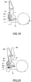
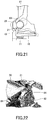
- FIGs. 19 through 21 are drawings illustrating how relevant components work when the opening knob 80 is operated.
- FIG. 19 illustrates a state where the shaft 21 of the platen roller 20 is supported by the support 83.
- Dotted lines in FIGs. 20 and 21 illustrate a state where the support 83 is disengaged from the shaft 21 as a result of moving the opening knob 80.
- the back side of the thermal head 10 is biased upward in the illustration by a spring 11, and the thermal head 10 is in contact with the platen roller 20.
- the second case 70 is caused by the leftward biasing force to move to the left relative to the first case 60, and the first case 60 and the second case 70 are separated from each other.
- a torsion spring 84 is connected to the lock lever 81.
- the torsion spring 84 biases the lock lever 81 to return to a position where the support 83 supports the shaft 21.
- An end of the torsion spring 84 is fixed to the frame of the head module, and another end of the torsion spring 84 engages with the lock lever 81.
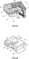
- FIG. 23 is a cross-sectional view of the printer 100 in a state where the first case 60 and the second case 70 are joined together.
- FIG. 24 is a cross-sectional view of the printer 100 in a state where the first case 60 and the second case 70 are separated from each other by moving the opening knob 80.
- the head module and the cutter module are joined together, and the platen roller 20 is pressed against the thermal head 10.
- the opening knob 80 is moved in the state of FIG. 23
- the second case 70 slides to the left and is separated from the first case 60 as illustrated in FIG. 24 , and the cutter module and the head module become detachable from each other. Also, as illustrated in FIG.
- FIGs. 25 and 26 are perspective views of the printer 100 in a state where the first case 60 and the second case 70 are separated from each other.
- a pair of sliding parts 73 are provided in the middle of a bottom surface 72 of the second case 70.
- Each of the sliding parts 73 includes a vertical portion extending upward and a horizontal portion extending horizontally from an end of the vertical portion, and has an L-shape.
- a groove 63 is formed in the middle of a bottom surface 62 of the first case 60.
- the groove 63 extends in a direction in which the first case 60 moves relative to the second case 70.
- a screw hole is formed in the groove 63, and the width of the groove 63 is substantially the same as the distance between the horizontal portions of two sliding parts 73.
- the first case 60 includes a support 64 in which a hole for inserting a screw 65 is formed.
- the sliding parts 73 are placed in the groove 63, the support 64 is placed on the lower surfaces of the sliding parts 73, and the screw 65 is passed through the hole in the support 64 and screwed into the screw hole formed in the groove 63.
- a gap is provided between the horizontal portions of the two sliding parts 73 so that the sliding parts 73 can slide in the groove 63 without interfering with the screw 65.
- the first case 60 and the second case 70 can be joined together as illustrated in FIG. 23 and can be separated from each other as illustrated in FIG. 24 .
- the sliding parts 73 are slidably supported between the groove 63 and the support 64. This configuration makes it possible to prevent the second case 70 from being completely detached from the first case 60 when the second case 70 is separated from the first case 60.
- the sliding movement of the first case 60 stops when ends 73a of the sliding parts 73 contact an end 63a of the groove 63 which is closer to the second case 70.
- the first case 60 is closest to the second case 70. In this state, the distance between the end 63a and the ends 73a is largest.
- the sliding parts 73 can move between a position at which the first case 60 and the second case 70 are joined and the end 63a and the ends 73a are furthest from each other, and a position at which the sliding parts 73 contact the end 63a.
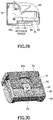
- FIGs. 27 through 29 illustrate a movable range of the sliding parts 73. With the configuration where the ends 73a of the sliding parts 73 contact the end 63a, it is possible to limit the distance that the first case 60 can move relative to the second case 70, and prevent the first case 60 from being completely detached from the second case 70.
- FIG. 27 is a bottom perspective view
- FIG. 28 is a bottom view
- FIG. 29 is a cross-sectional view of the printer 100 in a state where the first case 60 and the second case 70 are joined together.
- FIG. 30 is a bottom perspective view
- FIG. 31 is a bottom view
- FIG. 32 is a cross-sectional view of the printer 100 in a state where the first case 60 and the second case 70 are separated from each other.
- FIG. 33 is a cross-sectional perspective view of the printer 100.
- the printer 100 is configured such that the first case 60 can be attached to the second case 70 by turning the screw 65 with, for example, a coin, i.e., without using a tool such as a screwdriver.
- the printer 100 of the present embodiment can be installed, as a printer module, on a wall of another device such as a receipt issuing device ("ticketing device" is used hereafter as a generic term indicating such a device).
- ticketing device is used hereafter as a generic term indicating such a device.
- the printer 100 can be installed in a ticketing device by screwing a back surface 74 of the second case 70, where the paper-ejection port 71 is formed, to a wall 210 of the ticketing device.
- An opening 211 for ejecting the recording paper 200 is formed in the wall 210 of the ticketing device at a position corresponding to the paper-ejection port 71 of the printer 100.
- FIG. 35 is a perspective view of the printer 100 that is oriented such that the paper-feed port 61 faces upward.
- FIG. 36 is a perspective view of the printer 100 that is installed on the wall 210 of the ticketing device in the orientation illustrated in FIG. 35 .
- the upper side of the recording paper 200 is the back surface that is opposite the printed surface, i.e., the lower side of the recording paper 200 is the printed surface.
- FIG. 37 is a perspective view of the printer 100 that is oriented such that the paper-feed port 61 faces downward.
- FIG. 38 is a perspective view of the printer 100 that is installed on the wall 210 in the orientation illustrated in FIG. 37 . In the case of FIGs. 37 and 38 , the upper side of the recording paper 200 is the printed surface.
- FIG. 39 is a perspective view of the printer 100 that is oriented such that the paper-ejection port 71 faces upward.
- FIG. 40 is a perspective view of the printer 100 that is installed on the wall 210 in the orientation illustrated in FIG. 39 .
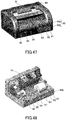
- FIG. 41 is a perspective view of the printer 100 that is oriented such that the paper-ejection port 71 faces downward.
- FIG. 42 is a perspective view of the printer 100 that is installed on the wall 210 in the orientation illustrated in FIG. 41 .
- the printer 100 of the present embodiment can be installed by screwing the bottom surface 72 of the second case 70 to the wall 210 of the ticketing device.
- the opening 211 for ejecting the recording paper 200 is formed in a wall 212, which is perpendicular to the wall 210 on which the printer 100 is attached, at a position corresponding to the paper-ejection port 71.
- the recording paper 200 is ejected upward in FIGs. 39 and 40 , and ejected downward in FIGs. 41 and 42 .
- the printer 100 and a holder 220 for holding the rolled recording paper 200 can be attached to the wall 210 and/or the wall 212.
- the printer 100 can be configured as a cutter-less printer by attaching, instead of the cutter module, the platen module that does not include the cutter 30 to the second case 70.
- a platen roller unit (platen module) 22 including the platen roller 20 is attached to the second case 70.
- FIG. 44 is a perspective view and FIG. 45 is a cross-sectional perspective view of the cutter-less printer in a state where the first case 60 and the second case 70 are joined together.
- FIG. 46 is a perspective view of the cutter-less printer in a state where the first case 60 and the second case 70 are separated from each other.
- the platen roller 20 can be moved away from the thermal head 10 by operating the opening knob 80 and thereby moving the first case 60 relative to the second case 70 as illustrated in FIG. 46 .
- the printer 100 of the present embodiment can be used not only as a printer unit to be installed in a ticketing device, but also as a stand-alone printer as illustrated in FIGs. 47 and 48 .
- an operations panel for operating the printer 100 is provided on the front surface of the lower case 60b.
- a light-emitting diode (LED) 91 indicating the operational state of the printer 100
- a cut key 92 operated to cut the recording paper 200
- a feed key 93 operated to feed the recording paper 200
- an RS232C terminal 94 that is an interface
- a universal serial bus (USB) terminal 95 operated to feed the recording paper 200
- an AC adaptor terminal 96 for power supply are provided on the front surface of the lower case 60b.
- a control board 97 is provided in the first case 60 to enable the printer 100 to function as a stand-alone device.
- the components illustrated in FIGs. 47 and 48 are examples. Some of those components may be omitted, and other components may be added to the printer 100.
- the printer 100 When the printer 100 is installed in a ticketing device as a module, the printer 100 may be configured to include the control board 97 or to include no control board as illustrated in FIG. 49 . In the latter case, the printer 100 may be controlled by, for example, a controller of the ticketing device.
- a presenter 230 may be connected to the printer 100 at a position corresponding to the paper-ejection port 71 of the second case 70.
- the presenter 230 retracts the recording paper 200 that is not pulled out by a user.
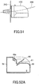
- a bezel 240 may be connected to the printer 100 to improve the appearance and the design of the paper-ejection port 71.
- the printer 100 of the present embodiment includes a flapper 66 disposed in a position corresponding to the paper-feed port 61 of the first case 60.
- the flapper 66 is attached to the first case 60 so as to be rotatable about a rotational shaft 66a.
- the flapper 66 is closed and functions as a guide for the recording paper 200.
- the flapper 66 is lifted and opened as illustrated in FIGs. 53A and 53B to widen the paper-feed port 61 and make it easier to remove the recording paper 200.
- a plate spring 67 for biasing the flapper 66 in the closing direction may be connected to the flapper 66. With the biasing force of the plate spring 67, the flapper 66 can function as a damper for tensioning the recording paper 200 that is fed through the paper-feed port 61. Also, as illustrated in FIG. 54B , a torsion spring 68 may be used in place of the plate spring 67.
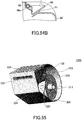
- FIG. 55 is a perspective view of the printing device 1000
- FIGs. 56 and 57 are perspective views of a housing 300.
- the printing device 1000 of the second embodiment includes the housing 300 and the printer 100 of the first embodiment.
- the printer 100 and a paper roll 200 are placed in the housing 300.
- the housing 300 includes an area 310 where the paper roll 200 is placed, and an area 320 where the printer 100 is placed.
- a paper-feed shaft 311 for supporting the paper roll 200 is provided in the area 310. Recording paper on which information is printed by the printer 100 is ejected from the paper-ejection port 71, and then ejected from a paper-ejection port 321 of the housing 300.
- the housing 300 includes flat outer surfaces including a first installation surface 301 and a second installation surface 302.
- the printing device 1000 may be installed such that either the first installation surface 301 or the second installation surface 302 contacts the desk or the wall.
- a third installation surface 303 which is a side surface of the housing 300, may be placed on the desk or the wall.
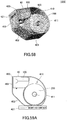
- FIG. 58 is a perspective view of a printing device 1000' of a variation of the second embodiment.
- the printing device 1000' includes a housing 400 and the printer 100.
- the paper roll 200 is placed in the housing 400.
- the housing 400 includes an area 410 where the paper roll 200 is placed, and an area 420 where the printer 100 is placed.
- a paper-feed shaft 411 is provided in the area 410. Recording paper is ejected from a paper-ejection port 421.
- the housing 400 includes flat outer surfaces including a first installation surface 401, a second installation surface 402, and a third installation surface 403.
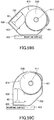
- the printing device 1000' may be installed such that the first installation surface 401 contacts a mounting surface as illustrated in FIG. 59A , the second installation surface 402 contacts the mounting surface as illustrated in FIG. 59B , or the third installation surface 403 contacts the mounting surface as illustrated in FIG. 59C .
Landscapes
- Handling Of Sheets (AREA)
- Accessory Devices And Overall Control Thereof (AREA)
- Electronic Switches (AREA)
- Advancing Webs (AREA)
Abstract
Description
- An aspect of this disclosure relates to a printer.
- Printers for issuing receipts are widely used, for example, for cash registers in stores and automated teller machines (ATM) in banks. In such a printer, information is printed on recording paper by a print head while the recording paper is being fed, and the recording paper is cut by a cutter.
- A paper roll is used as the recording paper for this type of printer.
-
- [Patent Document 1] Japanese Laid-Open Patent Publication No.
2013-010269 - [Patent Document 2] Japanese Laid-Open Patent Publication No.
2009-096595 - A printer includes structures for holding a paper roll, such as a paper-feed shaft for supporting the paper roll and a recording-paper holder for housing the paper roll.
- Also, a printer used as a built-in unit of a ticketing device for issuing receipts and a printer used as a stand-alone device have different purposes, are used in different environments, and have different design concepts, and therefore have different configurations. However, if a printer used as a stand-alone device can also be used as a built-in unit, it is possible to use the same components for them and provide printers with low costs.
- In an aspect of this disclosure, there is provided a printer that includes a recording head; a platen roller; a first case to which the recording head is attached, the first case including a paper-feed port for feeding recording paper; a second case to which the platen roller is attached, the second case including a paper-ejection port for ejecting the recording paper; and a lock lever that is disposed in the first case and includes a support configured to rotatably support a shaft of the platen roller. The printer is configured such that the shaft of the platen roller is placed in the support when the first case and the second case are joined together.
- An aspect of this disclosure makes it possible to provide a printer that can be used both as a stand-alone device and as a built-in unit of a device.
-
-
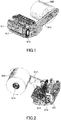
FIG. 1 is a perspective view of a printer including a paper-feed shaft; -
FIG. 2 is an internal perspective view of a printer including a paper-feed shaft; -
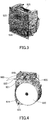
FIG. 3 is a perspective view of a printer including a recording-paper holder for housing recording paper; -
FIG. 4 is an internal perspective view of a printer including a recording-paper holder for housing recording paper; -
FIG. 5 is a perspective view of a printer of a first embodiment; -
FIG. 6 is a side view of a printer of the first embodiment; -
FIG. 7 is a cross-sectional perspective view of a printer of the first embodiment; -
FIG. 8 is a cross-sectional perspective view of a printer of the first embodiment; -
FIG. 9 is a perspective view of a printing mechanism of a printer of the first embodiment; -
FIG. 10 is a cross-sectional perspective view of a cutter-less printer of the first embodiment; -
FIG. 11 is a perspective view of a cutter-less printing mechanism of the first embodiment; -
FIG. 12 is a perspective view of a cutter-less printing mechanism of the first embodiment; -
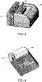
FIG. 13 is a drawing illustrating a state where a first case and a second case are separated from each other; -
FIG. 14 is a drawing illustrating a state where a first case and a second case are separated from each other; -
FIG. 15 is a drawing illustrating how to remove recording paper from a printer; -
FIG. 16 is a drawing illustrating a lock lever; -
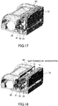
FIG. 17 is a drawing illustrating a lock lever; -
FIG. 18 is a drawing illustrating a lock lever; -
FIG. 19 is a drawing illustrating a lock lever; -
FIG. 20 is a drawing illustrating a lock lever; -
FIG. 21 is a drawing illustrating a lock lever; -
FIG. 22 is a drawing illustrating a lock lever; -
FIG. 23 is a cross-sectional view of a printer of the first embodiment; -
FIG. 24 is a cross-sectional view of a printer of the first embodiment; -
FIG. 25 is a perspective view of a printer of the first embodiment; -
FIG. 26 is a perspective view of a printer of the first embodiment; -
FIG. 27 is a bottom perspective view of a printer of the first embodiment; -
FIG. 28 is a bottom view of a printer of the first embodiment; -
FIG. 29 is a cross-sectional view of a printer of the first embodiment; -
FIG. 30 is a bottom perspective view of a printer of the first embodiment; -
FIG. 31 is a bottom view of a printer of the first embodiment; -
FIG. 32 is a cross-sectional view of a printer of the first embodiment; -
FIG. 33 is a cross-sectional perspective view of a printer of the first embodiment; -
FIG. 34 is a perspective view of a printer of the first embodiment; -
FIG. 35 is a drawing illustrating a method of attaching a printer to a ticketing device; -
FIG. 36 is a drawing illustrating a method of attaching a printer to a ticketing device; -
FIG. 37 is a drawing illustrating a method of attaching a printer to a ticketing device; -
FIG. 38 is a drawing illustrating a method of attaching a printer to a ticketing device; -
FIG. 39 is a drawing illustrating a method of attaching a printer to a ticketing device; -
FIG. 40 is a drawing illustrating a method of attaching a printer to a ticketing device; -
FIG. 41 is a drawing illustrating a method of attaching a printer to a ticketing device; -
FIG. 42 is a drawing illustrating a method of attaching a printer to a ticketing device; -
FIG. 43A is a drawing illustrating a method of attaching a printer to a ticketing device; -
FIG. 43B is a drawing illustrating a method of attaching a printer to a ticketing device; -
FIG. 43C is a drawing illustrating a method of attaching a printer to a ticketing device; -
FIG. 44 is a perspective view of a cutter-less printer of the first embodiment; -
FIG. 45 is a cross-sectional perspective view of a cutter-less printer of the first embodiment; -
FIG. 46 is a perspective view of a cutter-less printer of the first embodiment; -
FIG. 47 is a perspective view of a stand-alone printer of the first embodiment; -
FIG. 48 is an internal perspective view of a stand-alone printer of the first embodiment; -
FIG. 49 is an internal perspective view of a printer including no control board; -
FIG. 50 is a drawing illustrating a printer to which a presenter is connected; -
FIG. 51 is a drawing illustrating a printer to which a bezel is connected; -
FIG. 52A is a drawing illustrating a flapper; -
FIG. 52B is a drawing illustrating a flapper; -
FIG. 53A is a drawing illustrating a flapper; -
FIG. 53B is a drawing illustrating a flapper; -
FIG. 54A is a drawing illustrating a flapper; -
FIG. 54B is a drawing illustrating a flapper; -
FIG. 55 is a perspective view of a printing device of a second embodiment; -
FIG. 56 is a perspective view of a housing of a printing device of the second embodiment; -
FIG. 57 is a perspective view of a housing of a printing device of the second embodiment; -
FIG. 58 is a perspective view of a printing device of a variation of the second embodiment; -
FIG. 59A is a drawing illustrating a way to install a printing device of the variation of the second embodiment; -
FIG. 59B is a drawing illustrating a way to install a printing device of the variation of the second embodiment; and -
FIG. 59C is a drawing illustrating a way to install a printing device of the variation of the second embodiment. - Embodiments of the present invention are described below. The same reference number is assigned to the same component, and repeated descriptions of the same component are omitted.
- A printer including a paper-feed shaft for supporting rolled recording paper (which is hereafter also referred to as a "paper roll") is described with reference to
FIGs. 1 and 2 . The printer includes aprinting unit 910 for printing information on recording paper and acutter 911 for cutting the recording paper. The recording paper cut by thecutter 911 is ejected from apaper ejection port 912. Apaper roll 900 is installed by passing a paper-feed shaft 914 connected to anarm 913 through an opening in the center of thepaper roll 900. The printer also includes acontrol board 915 for controlling the printer.FIG. 1 is a perspective view andFIG. 2 is an internal perspective view of the printer. - Next, a printer including a recording-paper holder for housing a paper roll is described with reference to
FIGs. 3 and 4 . The printer includes aprinting unit 920 and acutter 921. Recording paper cut by thecutter 921 is ejected from apaper ejection port 922. Apaper roll 900 is placed in a recording-paper holder 923 of the printer. The printer also includes acontrol board 925 for controlling the printer.FIG. 3 is a perspective view andFIG. 4 is an internal perspective view of the printer. - The printers illustrated by
FIGs. 1 through 4 cannot be used as built-in units of devices such as ticketing devices without drastically changing their designs. - Next, a
printer 100 of a first embodiment is described with reference toFIGs. 5 through 12 .FIG. 5 is a perspective view,FIG. 6 is a side view, andFIGs. 7 and 8 are cross-sectional perspective views of theprinter 100 to which acutter 30 is attached.FIG. 9 is a perspective view of a printing mechanism provided in theprinter 100.FIG. 10 is a perspective view of theprinter 100 to which thecutter 30 is not attached.FIGs. 11 and 12 are perspective views of a printing mechanism to which thecutter 30 is not attached. - The
printer 100 is formed by joining a block (head module) including athermal head 10 that is a recording head and a block (cutter module) including aplaten roller 20 and thecutter 30. InFIG. 9 , the head module and the cutter module are joined together, the cutter module is disposed in the front side, and the head module is disposed in the rear side. - The
thermal head 10, a feedingmotor 40, and acutter motor 50 constitute the head module that is housed in afirst case 60. Theplaten roller 20 is driven by the feedingmotor 40. Theplaten roller 20 and thecutter 30 constitute the cutter module that is attached to asecond case 70. Thecutter 30 includes a fixedblade 31 and amovable blade 32 that is moved by thecutter motor 50 in a vertical direction in the figures. - The
first case 60 includes anupper case 60a and alower case 60b that can be separated from each other. In the present embodiment, thefirst case 60 is formed of a resin, and thesecond case 70 is formed of a sheet metal. However, thefirst case 60 and thesecond case 70 may also be formed of other materials. - Recording paper 200 (see
FIG. 15 ) is inserted through a paper-feed port 61 of thefirst case 60 into theprinter 100, passes through a gap between thethermal head 10 and theplaten roller 20 where information is printed on therecording paper 200, and is ejected from a paper-ejection port 71 formed in thesecond case 70. - The
printer 100 can be configured as a cutter-equipped printer as illustrated inFIGs. 5 through 9 by providing the cutter module in thesecond case 70. Also, theprinter 100 can be configured as a cutter-less printer as illustrated inFIGs. 10 through 12 by attaching a platen module, instead of the cutter module, to thesecond case 70. The platen module includes theplaten roller 20 but does not include thecutter 30. The same printer can be configured either as a cutter-equipped printer or a cutter-less printer by attaching one of the cutter module and the platen module to thesecond case 70. -
FIGs. 11 and 12 illustrate a printing mechanism formed by combining the platen module and the head module. The platen module is disposed in the front side inFIG. 11 (the rear side inFIG. 12 ), and the head module is disposed in the font side inFIG. 12 (the rear side inFIG. 11 ). Because thecutter 30 is not provided in the platen module, thecutter motor 50 is not provided in the head module nor the platen module. - Hereafter, when it is not necessary to distinguish between the cutter module and the platen module, both of the cutter module and the platen module may be referred to as the "cutter module".
- In the cutter-equipped printer, a
frame part 70a is provided between thefirst case 60 and thesecond case 70. In contrast, theframe part 70a is not provided in the cutter-less printer. Theframe part 70a has a width that corresponds to the difference in size (thickness) between the cutter module and the platen module, and is used to adjust the length of the case to the cutter-equipped or cutter-less printer. In the illustrated examples, the configuration of thesecond case 70 is changed to suit each one of the cutter-equipped and cutter-less printers. However, thesecond case 70 with the same configuration may be used for both types of printers. - As illustrated in
FIGs. 5 and7 , theprinter 100 can print information on therecording paper 200 in a state where thefirst case 60 and thesecond case 70 are joined together. By moving anopening knob 80 in this state, thefirst case 60 can be separated from thesecond case 70 as illustrated inFIGs. 13 and 14 . Separating thefirst case 60 and thesecond case 70 makes it easier to remove recording paper jammed in theprinter 100. - When the
recording paper 200 is jammed, the openingknob 80 is moved to move and separate thefirst case 60 from thesecond case 70, and therecording paper 200 is removed as illustrated inFIG. 15 . As illustrated inFIGs. 16 through 18 , the openingknob 80 is connected to alock lever 81 that rotates about arotational shaft 82, and ashaft 21 of theplaten roller 20 is rotatably supported by asupport 83 of thelock lever 81. The head module and the cutter module are joined together in a state where theshaft 21 of theplaten roller 20 is supported by thesupport 83.FIGs. 16 and17 are cross-sectional perspective views of theprinter 100 in a state where thefirst case 60 and thesecond case 70 are joined together, and theshaft 21 is supported by thesupport 83.FIG. 18 is a cross-sectional perspective view of theprinter 100 in a state where thefirst case 60 and thesecond case 70 are separated from each other, and theshaft 21 is disengaged from thesupport 83. When thefirst case 60 is separated from thesecond case 70, a gap is formed between thefirst case 60 and thesecond case 70 as illustrated inFIG. 18 . -
FIGs. 19 through 21 are drawings illustrating how relevant components work when the openingknob 80 is operated.FIG. 19 illustrates a state where theshaft 21 of theplaten roller 20 is supported by thesupport 83. Dotted lines inFIGs. 20 and21 illustrate a state where thesupport 83 is disengaged from theshaft 21 as a result of moving the openingknob 80. - In the state of
FIG. 19 where the cutter module and the head module are joined together, the back side of thethermal head 10 is biased upward in the illustration by aspring 11, and thethermal head 10 is in contact with theplaten roller 20. - As illustrated in
FIG. 20 , when the openingknob 80 is moved, thelock lever 81 rotates about therotational shaft 82 and moves to the right inFIG. 20 . As a result, thesupport 83 is disengaged from theshaft 21 of theplaten roller 20, and the head module and the cutter module are disengaged from each other. When theshaft 21 is released from thesupport 83, thethermal head 10 moves upward due to the biasing force of thespring 11, and theplaten roller 20 is biased upward. However, because the cutter module including theplaten roller 20 is fixed to thesecond case 70, the upward movement of theplaten roller 20 is restricted, and theplaten roller 20 is biased to the left as indicated by a dotted line inFIG. 21 . Because the platen module and the head module are disengaged from each other, thesecond case 70 is caused by the leftward biasing force to move to the left relative to thefirst case 60, and thefirst case 60 and thesecond case 70 are separated from each other. As illustrated inFIG. 22 , atorsion spring 84 is connected to thelock lever 81. Thetorsion spring 84 biases thelock lever 81 to return to a position where thesupport 83 supports theshaft 21. An end of thetorsion spring 84 is fixed to the frame of the head module, and another end of thetorsion spring 84 engages with thelock lever 81. -
FIG. 23 is a cross-sectional view of theprinter 100 in a state where thefirst case 60 and thesecond case 70 are joined together.FIG. 24 is a cross-sectional view of theprinter 100 in a state where thefirst case 60 and thesecond case 70 are separated from each other by moving the openingknob 80. In the state ofFIG. 23 , the head module and the cutter module are joined together, and theplaten roller 20 is pressed against thethermal head 10. When the openingknob 80 is moved in the state ofFIG. 23 , thesecond case 70 slides to the left and is separated from thefirst case 60 as illustrated inFIG. 24 , and the cutter module and the head module become detachable from each other. Also, as illustrated inFIG. 24 , when thesecond case 70 moves away from thefirst case 60 in the direction indicated by an arrow, theplaten roller 20 is brought out of contact with thethermal head 10 and a gap is formed between theplaten roller 20 and thethermal head 10. As a result, a path for feeding therecording paper 200 is opened, and jammed recording paper can be easily removed. -
FIGs. 25 and 26 are perspective views of theprinter 100 in a state where thefirst case 60 and thesecond case 70 are separated from each other. A pair of slidingparts 73 are provided in the middle of abottom surface 72 of thesecond case 70. Each of the slidingparts 73 includes a vertical portion extending upward and a horizontal portion extending horizontally from an end of the vertical portion, and has an L-shape. Also, as illustrated inFIGs. 27, 28 ,30 , and31 , agroove 63 is formed in the middle of abottom surface 62 of thefirst case 60. Thegroove 63 extends in a direction in which thefirst case 60 moves relative to thesecond case 70. A screw hole is formed in thegroove 63, and the width of thegroove 63 is substantially the same as the distance between the horizontal portions of two slidingparts 73. Thefirst case 60 includes asupport 64 in which a hole for inserting ascrew 65 is formed. - To attach the
first case 60 to thesecond case 70, the slidingparts 73 are placed in thegroove 63, thesupport 64 is placed on the lower surfaces of the slidingparts 73, and thescrew 65 is passed through the hole in thesupport 64 and screwed into the screw hole formed in thegroove 63. A gap is provided between the horizontal portions of the two slidingparts 73 so that the slidingparts 73 can slide in thegroove 63 without interfering with thescrew 65. - With the configuration where the sliding
parts 73 slide in thegroove 63 formed in thebottom surface 62 of thefirst case 60, thefirst case 60 and thesecond case 70 can be joined together as illustrated inFIG. 23 and can be separated from each other as illustrated inFIG. 24 . Thus, the slidingparts 73 are slidably supported between thegroove 63 and thesupport 64. This configuration makes it possible to prevent thesecond case 70 from being completely detached from thefirst case 60 when thesecond case 70 is separated from thefirst case 60. - In the present embodiment, as illustrated in
FIGs. 30 through 33 , the sliding movement of thefirst case 60 stops when ends 73a of the slidingparts 73 contact anend 63a of thegroove 63 which is closer to thesecond case 70. InFIGs. 27 and 28 , thefirst case 60 is closest to thesecond case 70. In this state, the distance between theend 63a and theends 73a is largest. Thus, the slidingparts 73 can move between a position at which thefirst case 60 and thesecond case 70 are joined and theend 63a and theends 73a are furthest from each other, and a position at which the slidingparts 73 contact theend 63a.FIGs. 27 through 29 illustrate a movable range of the slidingparts 73. With the configuration where theends 73a of the slidingparts 73 contact theend 63a, it is possible to limit the distance that thefirst case 60 can move relative to thesecond case 70, and prevent thefirst case 60 from being completely detached from thesecond case 70. -
FIG. 27 is a bottom perspective view,FIG. 28 is a bottom view, andFIG. 29 is a cross-sectional view of theprinter 100 in a state where thefirst case 60 and thesecond case 70 are joined together.FIG. 30 is a bottom perspective view,FIG. 31 is a bottom view, andFIG. 32 is a cross-sectional view of theprinter 100 in a state where thefirst case 60 and thesecond case 70 are separated from each other.FIG. 33 is a cross-sectional perspective view of theprinter 100. - As illustrated in
FIG. 34 , theprinter 100 is configured such that thefirst case 60 can be attached to thesecond case 70 by turning thescrew 65 with, for example, a coin, i.e., without using a tool such as a screwdriver. - The
printer 100 of the present embodiment can be installed, as a printer module, on a wall of another device such as a receipt issuing device ("ticketing device" is used hereafter as a generic term indicating such a device). For example, as illustrated inFIGs. 35 through 38 , theprinter 100 can be installed in a ticketing device by screwing aback surface 74 of thesecond case 70, where the paper-ejection port 71 is formed, to awall 210 of the ticketing device. Anopening 211 for ejecting therecording paper 200 is formed in thewall 210 of the ticketing device at a position corresponding to the paper-ejection port 71 of theprinter 100. -
FIG. 35 is a perspective view of theprinter 100 that is oriented such that the paper-feed port 61 faces upward.FIG. 36 is a perspective view of theprinter 100 that is installed on thewall 210 of the ticketing device in the orientation illustrated inFIG. 35 . In this case, the upper side of therecording paper 200 is the back surface that is opposite the printed surface, i.e., the lower side of therecording paper 200 is the printed surface.FIG. 37 is a perspective view of theprinter 100 that is oriented such that the paper-feed port 61 faces downward.FIG. 38 is a perspective view of theprinter 100 that is installed on thewall 210 in the orientation illustrated inFIG. 37 . In the case ofFIGs. 37 and 38 , the upper side of therecording paper 200 is the printed surface. -
FIG. 39 is a perspective view of theprinter 100 that is oriented such that the paper-ejection port 71 faces upward.FIG. 40 is a perspective view of theprinter 100 that is installed on thewall 210 in the orientation illustrated inFIG. 39 .FIG. 41 is a perspective view of theprinter 100 that is oriented such that the paper-ejection port 71 faces downward.FIG. 42 is a perspective view of theprinter 100 that is installed on thewall 210 in the orientation illustrated inFIG. 41 . As illustrated inFIGs. 39, 40 ,41, and 42 , theprinter 100 of the present embodiment can be installed by screwing thebottom surface 72 of thesecond case 70 to thewall 210 of the ticketing device. In this case, theopening 211 for ejecting therecording paper 200 is formed in awall 212, which is perpendicular to thewall 210 on which theprinter 100 is attached, at a position corresponding to the paper-ejection port 71. Therecording paper 200 is ejected upward inFIGs. 39 and 40 , and ejected downward inFIGs. 41 and 42 . - As illustrated in
FIGs. 43A through 43C , theprinter 100 and aholder 220 for holding the rolledrecording paper 200 can be attached to thewall 210 and/or thewall 212. - Next, a cutter-less printer is described with reference to
FIGs. 44 through 46 . Theprinter 100 can be configured as a cutter-less printer by attaching, instead of the cutter module, the platen module that does not include thecutter 30 to thesecond case 70. In the example ofFIGs. 44 through 46 , a platen roller unit (platen module) 22 including theplaten roller 20 is attached to thesecond case 70.FIG. 44 is a perspective view andFIG. 45 is a cross-sectional perspective view of the cutter-less printer in a state where thefirst case 60 and thesecond case 70 are joined together.FIG. 46 is a perspective view of the cutter-less printer in a state where thefirst case 60 and thesecond case 70 are separated from each other. - Also in the case of the cutter-less printer, the
platen roller 20 can be moved away from thethermal head 10 by operating the openingknob 80 and thereby moving thefirst case 60 relative to thesecond case 70 as illustrated inFIG. 46 . - The
printer 100 of the present embodiment can be used not only as a printer unit to be installed in a ticketing device, but also as a stand-alone printer as illustrated inFIGs. 47 and 48 . - In this case, for example, an operations panel for operating the
printer 100 is provided on the front surface of thelower case 60b. In the example ofFIGs. 47 and 48 , a light-emitting diode (LED) 91 indicating the operational state of theprinter 100, acut key 92 operated to cut therecording paper 200, afeed key 93 operated to feed therecording paper 200, anRS232C terminal 94 that is an interface, a universal serial bus (USB)terminal 95, and anAC adaptor terminal 96 for power supply are provided on the front surface of thelower case 60b. Also, as illustrated inFIG. 48 , acontrol board 97 is provided in thefirst case 60 to enable theprinter 100 to function as a stand-alone device. The components illustrated inFIGs. 47 and 48 are examples. Some of those components may be omitted, and other components may be added to theprinter 100. - When the
printer 100 is installed in a ticketing device as a module, theprinter 100 may be configured to include thecontrol board 97 or to include no control board as illustrated inFIG. 49 . In the latter case, theprinter 100 may be controlled by, for example, a controller of the ticketing device. - As illustrated in
FIG. 50 , apresenter 230 may be connected to theprinter 100 at a position corresponding to the paper-ejection port 71 of thesecond case 70. Thepresenter 230 retracts therecording paper 200 that is not pulled out by a user. Also, as illustrated inFIG. 51 , abezel 240 may be connected to theprinter 100 to improve the appearance and the design of the paper-ejection port 71. - As illustrated by
FIGs. 52A through 53B , theprinter 100 of the present embodiment includes aflapper 66 disposed in a position corresponding to the paper-feed port 61 of thefirst case 60. Theflapper 66 is attached to thefirst case 60 so as to be rotatable about arotational shaft 66a. During printing, as illustrated inFIGs. 52A and52B , theflapper 66 is closed and functions as a guide for therecording paper 200. For example, when removing therecording paper 200 jammed in theprinter 100, theflapper 66 is lifted and opened as illustrated inFIGs. 53A and53B to widen the paper-feed port 61 and make it easier to remove therecording paper 200. - Also, as illustrated in
FIG. 54A , aplate spring 67 for biasing theflapper 66 in the closing direction may be connected to theflapper 66. With the biasing force of theplate spring 67, theflapper 66 can function as a damper for tensioning therecording paper 200 that is fed through the paper-feed port 61. Also, as illustrated inFIG. 54B , atorsion spring 68 may be used in place of theplate spring 67. - Next, a
printing device 1000 according to a second embodiment is described.FIG. 55 is a perspective view of theprinting device 1000, andFIGs. 56 and 57 are perspective views of ahousing 300. - The
printing device 1000 of the second embodiment includes thehousing 300 and theprinter 100 of the first embodiment. - In the
printing device 1000, theprinter 100 and apaper roll 200 are placed in thehousing 300. Thehousing 300 includes anarea 310 where thepaper roll 200 is placed, and anarea 320 where theprinter 100 is placed. A paper-feed shaft 311 for supporting thepaper roll 200 is provided in thearea 310. Recording paper on which information is printed by theprinter 100 is ejected from the paper-ejection port 71, and then ejected from a paper-ejection port 321 of thehousing 300. - The
housing 300 includes flat outer surfaces including afirst installation surface 301 and asecond installation surface 302. When installing theprinting device 1000 on a desk or a wall, theprinting device 1000 may be installed such that either thefirst installation surface 301 or thesecond installation surface 302 contacts the desk or the wall. Also, athird installation surface 303, which is a side surface of thehousing 300, may be placed on the desk or the wall. -
FIG. 58 is a perspective view of a printing device 1000' of a variation of the second embodiment. The printing device 1000' includes ahousing 400 and theprinter 100. Thepaper roll 200 is placed in thehousing 400. Thehousing 400 includes anarea 410 where thepaper roll 200 is placed, and anarea 420 where theprinter 100 is placed. A paper-feed shaft 411 is provided in thearea 410. Recording paper is ejected from a paper-ejection port 421. - The
housing 400 includes flat outer surfaces including afirst installation surface 401, asecond installation surface 402, and athird installation surface 403. The printing device 1000' may be installed such that thefirst installation surface 401 contacts a mounting surface as illustrated inFIG. 59A , thesecond installation surface 402 contacts the mounting surface as illustrated inFIG. 59B , or thethird installation surface 403 contacts the mounting surface as illustrated inFIG. 59C . - Embodiments of the present invention are described above. However, the present invention is not limited to the specifically disclosed embodiments.
- The present application is based on and claims the benefit of priority of Japanese Patent Application No.
2015-083273 filed on April 15, 2015 -
- 10
- Thermal head
- 20
- Platen roller
- 21
- Shaft
- 30
- Cutter
- 40
- Feeding motor
- 50
- Cutter motor
- 60
- First case
- 60a
- Upper case
- 60b
- Lower case
- 61
- Paper-feed port>
- 62
- Bottom surface
- 63
- Groove
- 63a
- End
- 64
- Support
- 65
- Screw
- 66
- Flapper
- 70
- Second case
- 71
- Paper-ejection port
- 72
- Bottom surface
- 73
- Sliding part
- 74
- Back surface
- 80
- Opening knob
- 81
- Lock lever
- 82
- Rotational shaft
- 83
- Support
- 84
- Torsion spring
- 100
- Printer
- 200
- Recording paper
- 1000
- Printing device
- 1000'
- Printing device
Claims (7)
- A printer, comprising:a recording head;a platen roller;a first case to which the recording head is attached, the first case including a paper-feed port for feeding recording paper;a second case to which the platen roller is attached, the second case including a paper-ejection port for ejecting the recording paper; anda lock lever that is disposed in the first case and includes a support configured to rotatably support a shaft of the platen roller,wherein the printer is configured such that the shaft of the platen roller is placed in the support when the first case and the second case are joined together.
- The printer as claimed in claim 1, wherein
the second case includes a sliding part; the first case includes a groove in which the sliding part is placed; and
the printer is configured such that when the lock lever is operated, the sliding part slides in the groove and the second case moves relative to the first case. - The printer as claimed in claim 1, further comprising:a spring configured to bias the recording head toward the platen roller,wherein the printer is configured such that when the lock lever is operated, the support is disengaged from the shaft of the platen roller, the recording head is caused to press the platen roller by a biasing force of the spring, and the first case and the second case are separated from each other.
- The printer as claimed in claim 1, further comprising:a bezel that is connected to the second case at a position corresponding to the paper-ejection port.
- The printer as claimed in claim 1, further comprising:an operations panel and an interface disposed on one of the first case and the second case.
- A printing device, comprising:the printer of claim 1; anda housing including a printer holder that houses the printer, a recording paper holder configured to house recording paper, and a paper-ejection port for ejecting the recording paper.
- A printer, comprising:a first case including a recording head;a second case including a platen roller; anda lock disposed in the first case and configured to support a shaft of the platen roller,wherein the printer is configured such thatthe first case and the second case are joined together in a state where the shaft is supported by the lock, andthe first case is separable from the second case in a state where the shaft is disengaged from the lock.
Applications Claiming Priority (2)
| Application Number | Priority Date | Filing Date | Title |
|---|---|---|---|
| JP2015083273A JP2016203382A (en) | 2015-04-15 | 2015-04-15 | Printer |
| PCT/JP2016/059838 WO2016167108A1 (en) | 2015-04-15 | 2016-03-28 | Printer |
Publications (2)
| Publication Number | Publication Date |
|---|---|
| EP3284605A1 true EP3284605A1 (en) | 2018-02-21 |
| EP3284605A4 EP3284605A4 (en) | 2018-12-05 |
Family
ID=57125894
Family Applications (1)
| Application Number | Title | Priority Date | Filing Date |
|---|---|---|---|
| EP16779899.0A Withdrawn EP3284605A4 (en) | 2015-04-15 | 2016-03-28 | Printer |
Country Status (6)
| Country | Link |
|---|---|
| US (2) | US10357984B2 (en) |
| EP (1) | EP3284605A4 (en) |
| JP (1) | JP2016203382A (en) |
| KR (2) | KR20170128446A (en) |
| CN (1) | CN107405932A (en) |
| WO (1) | WO2016167108A1 (en) |
Families Citing this family (5)
| Publication number | Priority date | Publication date | Assignee | Title |
|---|---|---|---|---|
| WO2019064910A1 (en) * | 2017-09-28 | 2019-04-04 | アルプスアルパイン株式会社 | Thermal printer |
| JP7300339B2 (en) * | 2019-07-31 | 2023-06-29 | セイコーインスツル株式会社 | thermal printer |
| JP7809982B2 (en) * | 2021-12-28 | 2026-02-03 | ブラザー工業株式会社 | printer |
| JP7800133B2 (en) * | 2021-12-28 | 2026-01-16 | ブラザー工業株式会社 | printing device |
| CN115284752B (en) * | 2022-08-16 | 2023-07-14 | 恒银金融科技股份有限公司 | Thermosensitive receipt printer |
Family Cites Families (18)
| Publication number | Priority date | Publication date | Assignee | Title |
|---|---|---|---|---|
| JPH03172267A (en) * | 1989-11-27 | 1991-07-25 | Mita Ind Co Ltd | Data recorder |
| JPH06127051A (en) * | 1992-10-16 | 1994-05-10 | Tokyo Electric Co Ltd | Printer |
| US5833380A (en) | 1995-11-21 | 1998-11-10 | Seiko Epson Corporation | Printer having cutting apparatus and protective device for use in a printer |
| JP2002067435A (en) * | 2000-08-31 | 2002-03-05 | Alps Electric Co Ltd | Printer |
| US6447187B1 (en) * | 2000-10-25 | 2002-09-10 | Xac Automation Corporation | Restraining module for a cutter of a printer |
| JP3687912B2 (en) * | 2002-08-29 | 2005-08-24 | 東芝テック株式会社 | Printer unit |
| JP2004098625A (en) | 2002-09-12 | 2004-04-02 | Toshiba Tec Corp | Printer and product information processing device |
| JP4628747B2 (en) * | 2004-10-27 | 2011-02-09 | 富士通コンポーネント株式会社 | Thermal printer unit |
| JP4761465B2 (en) * | 2006-09-15 | 2011-08-31 | セイコーインスツル株式会社 | Thermal printer |
| JP2008094009A (en) * | 2006-10-13 | 2008-04-24 | Brother Ind Ltd | Printing device |
| JP2009078524A (en) * | 2007-09-27 | 2009-04-16 | Seiko Instruments Inc | Thermal printer |
| JP4992657B2 (en) | 2007-10-17 | 2012-08-08 | セイコーエプソン株式会社 | Roll paper supply device and roll paper printer |
| JP5394678B2 (en) | 2008-08-25 | 2014-01-22 | セイコーインスツル株式会社 | Thermal printer |
| JP5725750B2 (en) * | 2010-07-29 | 2015-05-27 | キヤノン株式会社 | Paper feeder |
| KR101432362B1 (en) | 2011-06-29 | 2014-08-20 | 후지쯔 콤포넌트 가부시끼가이샤 | Printer apparatus |
| JP5986716B2 (en) | 2011-06-29 | 2016-09-06 | 富士通コンポーネント株式会社 | Printer device |
| EP3278997B1 (en) * | 2011-10-07 | 2020-06-10 | Fujitsu Component Limited | Printer |
| JP6328963B2 (en) * | 2014-03-07 | 2018-05-23 | セイコーインスツル株式会社 | Printer with cutter |
-
2015
- 2015-04-15 JP JP2015083273A patent/JP2016203382A/en active Pending
-
2016
- 2016-03-28 KR KR1020177028876A patent/KR20170128446A/en not_active Ceased
- 2016-03-28 KR KR1020197016605A patent/KR20190069609A/en not_active Abandoned
- 2016-03-28 WO PCT/JP2016/059838 patent/WO2016167108A1/en not_active Ceased
- 2016-03-28 CN CN201680021384.2A patent/CN107405932A/en active Pending
- 2016-03-28 US US15/563,135 patent/US10357984B2/en not_active Expired - Fee Related
- 2016-03-28 EP EP16779899.0A patent/EP3284605A4/en not_active Withdrawn
-
2019
- 2019-06-06 US US16/433,329 patent/US20190283474A1/en not_active Abandoned
Also Published As
| Publication number | Publication date |
|---|---|
| CN107405932A (en) | 2017-11-28 |
| US20180079242A1 (en) | 2018-03-22 |
| US20190283474A1 (en) | 2019-09-19 |
| US10357984B2 (en) | 2019-07-23 |
| WO2016167108A1 (en) | 2016-10-20 |
| JP2016203382A (en) | 2016-12-08 |
| KR20190069609A (en) | 2019-06-19 |
| EP3284605A4 (en) | 2018-12-05 |
| KR20170128446A (en) | 2017-11-22 |
Similar Documents
| Publication | Publication Date | Title |
|---|---|---|
| US20190283474A1 (en) | Printer | |
| JP6533433B2 (en) | Printing unit and thermal printer | |
| CN115362067B (en) | Printing device | |
| US9969190B2 (en) | Cutter drive mechanism, cutter, and printer | |
| CN107688280B (en) | image forming apparatus | |
| JP6248599B2 (en) | Printing device | |
| EP2749427B1 (en) | Printer | |
| CN101161463B (en) | Electronic device | |
| EP2821234B1 (en) | Printer device | |
| EP3348409B1 (en) | Printer | |
| CN104669807A (en) | Printer and control method of a printer | |
| CN212073377U (en) | Thermal printer | |
| US8973913B2 (en) | Media conveyance device and printer | |
| CN204222391U (en) | Thermal printer | |
| EP2842758B1 (en) | Modular printer | |
| US8931970B1 (en) | Ticket printer | |
| US8550734B2 (en) | Transportation guide mechanism and recording device having the same | |
| US10668756B2 (en) | Printer | |
| KR20150076117A (en) | Printer | |
| JP2014195903A (en) | Recording device | |
| JP4710717B2 (en) | Printer device | |
| JP5850707B2 (en) | Printer | |
| JP2007111881A (en) | Method of holding and releasing holding of cut recording paper of printer | |
| JP2006205377A (en) | Inkjet recording device | |
| JP2001171206A (en) | Cover mounting structure and printer using this cover mounting structure |
Legal Events
| Date | Code | Title | Description |
|---|---|---|---|
| STAA | Information on the status of an ep patent application or granted ep patent |
Free format text: STATUS: THE INTERNATIONAL PUBLICATION HAS BEEN MADE |
|
| PUAI | Public reference made under article 153(3) epc to a published international application that has entered the european phase |
Free format text: ORIGINAL CODE: 0009012 |
|
| STAA | Information on the status of an ep patent application or granted ep patent |
Free format text: STATUS: REQUEST FOR EXAMINATION WAS MADE |
|
| 17P | Request for examination filed |
Effective date: 20171003 |
|
| AK | Designated contracting states |
Kind code of ref document: A1 Designated state(s): AL AT BE BG CH CY CZ DE DK EE ES FI FR GB GR HR HU IE IS IT LI LT LU LV MC MK MT NL NO PL PT RO RS SE SI SK SM TR |
|
| AX | Request for extension of the european patent |
Extension state: BA ME |
|
| DAV | Request for validation of the european patent (deleted) | ||
| DAX | Request for extension of the european patent (deleted) | ||
| A4 | Supplementary search report drawn up and despatched |
Effective date: 20181025 |
|
| RIC1 | Information provided on ipc code assigned before grant |
Ipc: B41J 29/00 20060101ALI20181020BHEP Ipc: B41J 15/04 20060101ALI20181020BHEP Ipc: B41J 11/04 20060101AFI20181020BHEP |
|
| STAA | Information on the status of an ep patent application or granted ep patent |
Free format text: STATUS: THE APPLICATION HAS BEEN WITHDRAWN |
|
| 18W | Application withdrawn |
Effective date: 20190712 |