EP3284604A1 - Image forming apparatus - Google Patents
Image forming apparatus Download PDFInfo
- Publication number
- EP3284604A1 EP3284604A1 EP17186667.6A EP17186667A EP3284604A1 EP 3284604 A1 EP3284604 A1 EP 3284604A1 EP 17186667 A EP17186667 A EP 17186667A EP 3284604 A1 EP3284604 A1 EP 3284604A1
- Authority
- EP
- European Patent Office
- Prior art keywords
- light
- mounting portion
- image forming
- forming apparatus
- receiving part
- Prior art date
- Legal status (The legal status is an assumption and is not a legal conclusion. Google has not performed a legal analysis and makes no representation as to the accuracy of the status listed.)
- Withdrawn
Links
- 238000013459 approach Methods 0.000 claims description 2
- 230000001154 acute effect Effects 0.000 claims 1
- 230000008859 change Effects 0.000 description 16
- 238000001514 detection method Methods 0.000 description 16
- 239000000758 substrate Substances 0.000 description 10
- 230000007246 mechanism Effects 0.000 description 9
- 238000005286 illumination Methods 0.000 description 6
- 238000010586 diagram Methods 0.000 description 5
- 230000002238 attenuated effect Effects 0.000 description 4
- 230000000694 effects Effects 0.000 description 3
- NIXOWILDQLNWCW-UHFFFAOYSA-N acrylic acid group Chemical group C(C=C)(=O)O NIXOWILDQLNWCW-UHFFFAOYSA-N 0.000 description 2
- 238000007599 discharging Methods 0.000 description 2
- 239000011521 glass Substances 0.000 description 2
- 239000000463 material Substances 0.000 description 2
- 238000002834 transmittance Methods 0.000 description 2
- 230000008901 benefit Effects 0.000 description 1
- 230000015572 biosynthetic process Effects 0.000 description 1
- 150000001875 compounds Chemical class 0.000 description 1
- 230000007423 decrease Effects 0.000 description 1
- 238000003384 imaging method Methods 0.000 description 1
- 238000004519 manufacturing process Methods 0.000 description 1
- 238000000034 method Methods 0.000 description 1
- 230000003287 optical effect Effects 0.000 description 1
- 230000008569 process Effects 0.000 description 1
- 230000001105 regulatory effect Effects 0.000 description 1
- 239000011347 resin Substances 0.000 description 1
- 229920005989 resin Polymers 0.000 description 1
- 230000000630 rising effect Effects 0.000 description 1
Images






Classifications
-
- G—PHYSICS
- G03—PHOTOGRAPHY; CINEMATOGRAPHY; ANALOGOUS TECHNIQUES USING WAVES OTHER THAN OPTICAL WAVES; ELECTROGRAPHY; HOLOGRAPHY
- G03G—ELECTROGRAPHY; ELECTROPHOTOGRAPHY; MAGNETOGRAPHY
- G03G15/00—Apparatus for electrographic processes using a charge pattern
- G03G15/50—Machine control of apparatus for electrographic processes using a charge pattern, e.g. regulating differents parts of the machine, multimode copiers, microprocessor control
- G03G15/5029—Machine control of apparatus for electrographic processes using a charge pattern, e.g. regulating differents parts of the machine, multimode copiers, microprocessor control by measuring the copy material characteristics, e.g. weight, thickness
-
- B—PERFORMING OPERATIONS; TRANSPORTING
- B41—PRINTING; LINING MACHINES; TYPEWRITERS; STAMPS
- B41J—TYPEWRITERS; SELECTIVE PRINTING MECHANISMS, i.e. MECHANISMS PRINTING OTHERWISE THAN FROM A FORME; CORRECTION OF TYPOGRAPHICAL ERRORS
- B41J2/00—Typewriters or selective printing mechanisms characterised by the printing or marking process for which they are designed
- B41J2/005—Typewriters or selective printing mechanisms characterised by the printing or marking process for which they are designed characterised by bringing liquid or particles selectively into contact with a printing material
- B41J2/01—Ink jet
-
- B—PERFORMING OPERATIONS; TRANSPORTING
- B41—PRINTING; LINING MACHINES; TYPEWRITERS; STAMPS
- B41J—TYPEWRITERS; SELECTIVE PRINTING MECHANISMS, i.e. MECHANISMS PRINTING OTHERWISE THAN FROM A FORME; CORRECTION OF TYPOGRAPHICAL ERRORS
- B41J11/00—Devices or arrangements of selective printing mechanisms, e.g. ink-jet printers or thermal printers, for supporting or handling copy material in sheet or web form
- B41J11/0025—Handling copy materials differing in width
- B41J11/003—Paper-size detection, i.e. automatic detection of the length and/or width of copy material
-
- B—PERFORMING OPERATIONS; TRANSPORTING
- B41—PRINTING; LINING MACHINES; TYPEWRITERS; STAMPS
- B41J—TYPEWRITERS; SELECTIVE PRINTING MECHANISMS, i.e. MECHANISMS PRINTING OTHERWISE THAN FROM A FORME; CORRECTION OF TYPOGRAPHICAL ERRORS
- B41J11/00—Devices or arrangements of selective printing mechanisms, e.g. ink-jet printers or thermal printers, for supporting or handling copy material in sheet or web form
-
- B—PERFORMING OPERATIONS; TRANSPORTING
- B41—PRINTING; LINING MACHINES; TYPEWRITERS; STAMPS
- B41J—TYPEWRITERS; SELECTIVE PRINTING MECHANISMS, i.e. MECHANISMS PRINTING OTHERWISE THAN FROM A FORME; CORRECTION OF TYPOGRAPHICAL ERRORS
- B41J11/00—Devices or arrangements of selective printing mechanisms, e.g. ink-jet printers or thermal printers, for supporting or handling copy material in sheet or web form
- B41J11/0095—Detecting means for copy material, e.g. for detecting or sensing presence of copy material or its leading or trailing end
-
- B—PERFORMING OPERATIONS; TRANSPORTING
- B41—PRINTING; LINING MACHINES; TYPEWRITERS; STAMPS
- B41J—TYPEWRITERS; SELECTIVE PRINTING MECHANISMS, i.e. MECHANISMS PRINTING OTHERWISE THAN FROM A FORME; CORRECTION OF TYPOGRAPHICAL ERRORS
- B41J29/00—Details of, or accessories for, typewriters or selective printing mechanisms not otherwise provided for
- B41J29/38—Drives, motors, controls or automatic cut-off devices for the entire printing mechanism
-
- G—PHYSICS
- G03—PHOTOGRAPHY; CINEMATOGRAPHY; ANALOGOUS TECHNIQUES USING WAVES OTHER THAN OPTICAL WAVES; ELECTROGRAPHY; HOLOGRAPHY
- G03G—ELECTROGRAPHY; ELECTROPHOTOGRAPHY; MAGNETOGRAPHY
- G03G15/00—Apparatus for electrographic processes using a charge pattern
- G03G15/65—Apparatus which relate to the handling of copy material
- G03G15/6502—Supplying of sheet copy material; Cassettes therefor
- G03G15/6514—Manual supply devices
-
- G—PHYSICS
- G03—PHOTOGRAPHY; CINEMATOGRAPHY; ANALOGOUS TECHNIQUES USING WAVES OTHER THAN OPTICAL WAVES; ELECTROGRAPHY; HOLOGRAPHY
- G03G—ELECTROGRAPHY; ELECTROPHOTOGRAPHY; MAGNETOGRAPHY
- G03G2215/00—Apparatus for electrophotographic processes
- G03G2215/00362—Apparatus for electrophotographic processes relating to the copy medium handling
- G03G2215/00535—Stable handling of copy medium
- G03G2215/00717—Detection of physical properties
- G03G2215/00734—Detection of physical properties of sheet size
Definitions
- the present invention relates to an image forming apparatus, and more specifically relates to an image forming apparatus such as a printer that can determine various sizes of a recording medium such as paper.
- image forming apparatuses such as those in patent documents 1 and 2, for example, are known as an image forming apparatus equipped with a size determining mechanism that can determine various sizes of a recording medium mounted on a mounting portion.
- an automatic document feeding device for an image forming apparatus equipped with a document detection sensor is disclosed.
- the document detection sensor is a reflective type optical sensor having a light emitter and a light receiving part, and the document detection sensor is configured so as to detect the document via a detection hole from below or inside a document feeding table.
- an image forming apparatus having a paper size detection device is disclosed.
- the paper size detection device is equipped with a guide member that can freely move for regulating an end portion of the paper contained in the paper cassette; a reflective member provided in the guide member, having a plurality of reflective surfaces in which the reflectance differs along the moving direction of the guide member; and a light receiving and emitting element for emitting light to the reflective surfaces of the reflective member, receiving the reflected light from the reflective surfaces, and outputting a detection signal corresponding to the amount of light received from the reflective surfaces.
- a form of a transmitting member having a plurality of transmitting surfaces with different transmittances is also disclosed instead of a form of a reflective member having a plurality of reflective surfaces.
- the sensor light emitted from the light emitter is reflected on the lower surface of the paper placed on the document feeding table via the detection holes, reaches the light receiving part, and is received by the light receiving part.
- the sensor light emitted from the light emitter is transmitted through the paper, and the light receiving part may not be able to properly receive the sensor light.
- external light such as indoor illumination and the like may be transmitted through the paper, and the light receiving part may receive external light other than the sensor light. That is, in the document detection sensor of patent document 1, erroneous detection occurs easily, and in some cases, detection of paper size may not be reliably and appropriately carried out.
- one or more embodiments of the invention may reliably and appropriately determine various sizes of a recording medium using a simple configuration.
- the image forming apparatus may be equipped with a housing; a mounting portion for mounting a recording medium, provided in the housing; at least one light receiving part provided in the housing; a change portion (such as, for example, a light adjuster) for changing the amount of light incident on the light receiving part based on the recording medium on the mounting portion, provided between the light receiving part and a light source for outputting light incident on the light receiving part; and a size determining part for determining size of the recording medium mounted in the housing, based on the amount of light received by the light receiving part that is changed by the change portion. Because it is possible to change the amount of light incident on the light receiving part based on the recording medium on the mounting portion using the changing portion, it is possible to reliably and appropriately determine various sizes of a recording medium using a simple configuration.
- the image forming apparatus may comprise a housing; a mounting portion in the housing that is configured to hold a recording medium; one or more light receivers in the housing; a light adjuster that adjusts an amount of light incident on the light receivers based on presence or size of the recording medium on the mounting portion; and a controller that determines a size of the recording medium based on the amount of light that has been adjusted by the light adjuster.
- FIG. 1 illustrates a printer 1 according to one or more embodiments of the present invention.
- the printer 1 is an embodiment of the imaging formation device, and is applied, for example, as an inkjet printer.
- the position of a mounting portion 4 described later is set to the rear side of a housing 3 and the position of an ejection portion 5 is set to the front side (front surface side) of the housing 3.
- the horizontal direction orthogonal to the front and rear direction is the left and right direction
- the vertical direction orthogonal to the front and rear direction as well as the left and right direction is the up and down direction.
- the printer 1 is equipped with a device body 2.
- the device body 2 has a resin housing 3, and a mounting portion 4 for mounting a paper as the recording medium is provided on the rear side of the housing 3 corresponding to various sizes.
- the mounting portion 4 has a mounting surface 4a for mounting the paper of various sizes diagonally above.
- the mounting surface 4a is formed in a range from a left side portion 4b to a right side portion 4c of the mounting portion 4.
- the mounting surface 4a is inclined only at a predetermined angle (30° in the illustrated example) from the vertical direction so that the upper side faces the rear side of the housing 3.
- the right side portion 4c of the mounting portion 4 is set as a reference position E (see FIG. 1 ), and each paper is mounted on the mounting surface 4a in a state where the side portions of each paper are aligned with the reference position E.
- the ejection portion 5 is provided on the front side in the housing 3 to eject the paper fed from the mounting portion 4 into the housing 3.
- the paper mounted on the mounting surface 4a of the mounting portion 4 is sent to the ejection portion 5 along a transporting direction orthogonal to the width direction of the housing 3 using a feeding mechanism (not illustrated) provided in the housing 3.
- the device body 2 is equipped with a cartridge 6 having a nozzle (not illustrated) for discharging ink, and a carriage 7 on which the cartridge 6 is mounted.
- the carriage 7 is configured to be able to reciprocate in the left and right direction in the housing 3.
- An image or the like is printed on a paper fed from the mounting portion 4 into the housing 3 by discharging ink from the nozzle of the cartridge 6 while reciprocating the carriage 7 in the left and right direction within the housing 3.
- each through hole 8 is formed in substantially a triangular shape so as to taper in the transporting direction.
- the opening of each through hole 8 is formed in a right angle isosceles triangle in which the lower vertex angle is a right angle.
- each through hole 8 is formed to pass through from the mounting surface 4a to each light receiving part 12 described later.
- the through holes 8a, 8b, and 8c are disposed at intervals along the width direction of the housing 3 so as to correspond to each paper size mounted in the mounting portion 4.
- the through hole 8 a formed near the left side portion 4b of the mounting portion 4 is disposed so that the center of the left and right width thereof is positioned at a position separated from the reference position E only by the dimension X1.
- the through hole 8b formed second from the left side is disposed so that the center of the left and right width thereof is positioned at a position separated from the reference position E only by a dimension X2.
- the through hole 8c formed near the right side portion 4c of the mounting portion 4 is provided to detect the presence and absence of a paper mounted in the mounting portion 4.
- the dimension X1 corresponds to a length (297 mm) in the longitudinal direction in an A4 sized paper horizontally placed on the mounting surface 4a of the mounting portion 4, or a length (279.4 mm) in the longitudinal direction in a letter size paper.
- the dimension X2 corresponds to a length (257 mm) in the longitudinal direction in a B5 size paper horizontally placed on the mounting surface 4a of the mounting portion 4.
- each light receiving part 12 is stored in a storage space 13a in a storage space 13 described later.
- each light receiving part 12 is composed of, for example, a phototransistor for visible light. The light incident on the phototransistor is converted into a voltage in the phototransistor. The voltage is input in an AD converter (not illustrated) via an integrated circuit (not illustrated) in the device body 2, and is converted to a digital value using the AD converter. Then, the digital value is output to a size determining part 14 described later.
- an illumination light or the like installed on the outside of the housing 3 (for example, indoors) is used as the light source S, and the light output from the illumination light becomes the light L incident on each light receiving part 12.
- each light receiving part 12 is provided on a rectangular substrate 10.
- the plurality of light receiving part 12a, 12b, and 12c are placed at predetermined intervals along the longitudinal direction of the substrate 10 in a state rising in a direction orthogonal to the substrate 10 surface.
- the storage space 13 having a predetermined storage space 13a is provided on the opposite side of the mounting surface 4a of the mounting portion 4.
- the storage space 13 and the storage space 13a is formed so as to extend in the width direction of the housing 3.
- a support portion 13b protruding into the storage space 13a is integrally formed in the storage space 13, and the substrate 10 is fixed to the support portion 13b.
- each through hole 8 is disposed at a position shifted more upward than the position of each light receiving part 12 in the transporting direction of the paper P along the mounting surface 4a of the mounting portion 4.
- each light receiving part 12 is stored in the storage space 13a of the storage space 13 in a state hidden behind the mounting portion 4 as viewed from the front surface side of the housing 3.
- a circular region T indicated by a virtual line represents a standard region in which light can be received by the light receiving part 12, and each through hole 8 is disposed corresponding to each light receiving part 12 so that the opening is partially included in the circular region T.
- the light L output from the light source S passes through the through hole 8 and is incident on each light receiving part 12 so as to be along an inclined direction inclined upward by only a predetermined angle with respect to the protruding direction of the light receiving part 12 (see FIG. 4 ).
- the through hole 8 is disposed at a position shifted upward from the position of the light receiving part 12, as indicated by the virtual line in FIG. 4 , the light L passes through a region more narrow than the actual opening in the through hole 8 and incident in the light receiving part 12. That is, the incident angle of the light L when incident on the light receiving part 12 is limited by the positional relationship of the through hole 8 and the light receiving part 12, and the light L incident on the light receiving part 12 is narrowed.
- the light L slightly attenuates as it passes through the through hole 8.
- the amount of light L is slightly smaller than the amount of light immediately after being output from the light source S to being incident on the light receiving part 12 from the through hole 8.
- the opening of the through hole 8 as described above is partially included in the circular region T, even when the light receiving part 12 is hidden behind the mounting portion 4, the light L passing through the through hole 8 is directly incident on the light receiving part 12.
- the light L passes through the paper P so as to be inclined with respect to the thickness direction, and the light L is significantly attenuated in the process.
- the through hole 8 being disposed in a state shifted from the light receiving part 12, the light L incident on the light receiving part 12 is narrowed down in the through hole 8, and for example, compared to a state in which the position of the through hole 8 is aligned with the light receiving part 12, and the light L passes through in the vertical direction with respect to the paper P on the mounting surface 4a, it can be secured for a longer distance (attenuation distance) until the light L is incident on the light receiving part 12.
- the amount of light L incident on the light receiving part 12 significantly attenuates more than the light amount when output from the light source S.
- the printer 1 has a size determining part 14 for determining the size of each paper mounted on the mounting portion 4 based on the amount of light incident on the light receiving part 12, and the number and position of light receiving part 12 on which the light L is incident.
- the aspect for determining various sizes of paper are as follows.
- the size determining part 14 determines that an A4 size paper or a letter size paper is mounted on the mounting portion 4 in a horizontal state.
- the size determining part 14 when an output voltage (hereinafter “output voltage V2") is detected corresponding to when the amount of light L not attenuated from only light receiving part 12a is incident (that is, the light L guided from the through hole 8a to the direct light receiving part 12a without passing through the paper P), and when the output voltage V1 from the other light receiving part 12b and 12c are detected, the size determining part 14 determines that a B5 size paper is mounted on the mounting portion 4 in a horizontal state.
- output voltage V2 an output voltage
- the size determining part 14 when the output voltage V2 from both light receiving part 12a and 12b is detected, and when the output voltage V1 from the light receiving part 12c is detected, the size determining part 14, for example, determines that a postcard size paper, paper less than or equal to B5 size, envelope, L size, and the like is mounted in the mounting portion 4.
- the size determining part 14 when the output voltage V2 is detected from all of the light receiving part 12a, 12b, and 12c, the size determining part 14 determines that no paper of any size is mounted on the mounting portion 4.
- the size determining part 14 sends each determination result to a controller 15 composed of a CPU provided in the device body 2.
- the controller 15 operates each mechanism such as the carriage 7 and the like based on the determination results.
- the paper size determining part 14 may be implemented in software that is performed by the controller 15 or the CPU thereof.
- the through hole 8 is configured so that the path of the light L incident on the light receiving part 12 is narrowed in advance. Then, as described above, in a state in which there is paper P on the mounting portion 4, the amount of light L output from the light source S is significantly attenuated by the paper P and the though hole 8, and the amount of light L smaller than the state in which no paper P is on the mounting portion 4 is incident on the light receiving part 12. As a result, it is possible to reliably distinguish the amount of light L incident on the light receiving part 12 based on the paper P mounted on the mounting portion 4.
- the through hole 8 is provided between the light receiving part 12 and the light source S, and functions as a change portion (light adjuster) for changing the amount of light L when the light L from the light source S is incident on the light receiving part 12 based on the presence and absence of paper P on the mounting portion 4.
- the printer 1 it is possible to change the amount of light when the light L from the light source S is incident on the light receiving part 12 based on the paper P on the mounting portion 4, and reliably and appropriately determine the paper size so that erroneous detection does not occur.
- the printer 1 by providing a through hole 8 passing through from the mounting surface 4a of the mounting portion 4 to the light receiving part 12, the mechanism for detecting the paper size equipped with a change portion (light adjuster) can be simplified, and the cost of the device body in the printer 1 can be reduced.
- the storage space 13 having a storage space 13a for storing the light receiving part 12 is provided on the opposite side of the mounting surface 4a in the mounting portion 4, the light L guided from the through hole 8 can be effectively caused to be incident on the light receiving part 12.
- each through hole 8 is formed in substantially a triangular shape so as to taper toward the transporting direction, when setting the paper P on the mounting portion 4 (mounting surface 4a) along the transporting direction, the lower end portion of the paper P does not catch on each through hole 8, and the paper P can be smoothly mounted on the mounting portion 4 (mounting surface 4a).
- the printer 1 because an illumination light and the like on the outside of the housing 3 is used as the light source S, it is unnecessary to additionally provide a dedicated light emitter composed of an LED as the light source S, and the mechanism for detecting the paper size can be simplified, thus reducing the cost of the device body in the printer 1.
- FIG. 7 illustrates a variation of example 1. Note that in the following variation and the description of the embodiments, the same portions in FIG. 1 through 6 will be denoted by the same reference numerals, and a detailed description thereof will be omitted.
- each through hole 8 is formed at an incline with respect to the mounting surface 4a so as to pass through from the mounting surface 4a on the mounting portion 4 to each light receiving part 12.
- ⁇ 30° in the illustrated example
- the distance from the paper P to each light receiving part 12 is approximately doubled, and the attenuation distance of the light L can be secured to a longer distance.
- the amount of light L incident on the light receiving part 12 can more reliably be distinguished based on the presence and absence of paper P mounted on the mounting portion 4.
- the angle ⁇ in this variation is set to 30°, but it is not limited to this angle, and may be set to an angle less than 90°.
- the through hole 8 as the change portion (light adjuster) is illustrated, but it is not limited to this.
- it may be a light adjuster in which each through hole 8 is blocked by a transparent member such as a transparent glass member, acrylic member, and the like.
- the opening of each through hole 8 is not limited to the substantially triangular shape as described above, and may be formed in a polygonal shape including a square shape, or a circular shape. That is, the change portion (light adjuster) is provided between the light receiving part 12 and the light source S, and may function for changing the amount of light when the light L from the light source S is incident on the light receiving part 12 based on the presence and absence of paper P on the mounting portion 4.
- FIG. 8 through 14 illustrate the printer 1 according to one or more embodiments of the present invention.
- the specific configuration differs in the light source, the through hole, and the change portion. Note that in the following description, the same portions in FIG. 1 through 7 will be denoted by the same reference numerals, and a detailed description thereof will be omitted.
- a plurality (three in the illustrated example) of through holes 20 (20a, 20b, 20c) formed passing through in a substantially rectangular shape are provided in the mounting portion 4.
- the through holes 20a, 20b, and 20c, similar to example 1, are disposed at intervals along the width direction of the housing 3 in positions to correspond to each paper P size mounted in the mounting portion 4.
- a plurality (three in the illustrated example) of light receiving part 12 (12a, 12b, 12c) composed of a phototransistor are provided in the housing 3. Furthermore, a plurality (three in the illustrated example) of light emitters 11 (11a, 11b, 11c) composed of an LED element are provided as the light source in the housing 3, and the light output from the end portion of each light emitter 11 is the light L incident on the end portion of each light receiving part 12.
- each light emitter 11 and each light receiving part 12 are disposed close to each other so as to form a pair on positions corresponding to the position of each through hole 20 on the opposite side (back side) of the mounting surface 4a on the mounting portion 4.
- each light emitter 11 and each light receiving part 12 are placed at a predetermined interval on the substrate 10 along the longitudinal direction of the substrate 10 in a state raising in a vertical direction with respect to the back side of the substrate 10 and, for example, forming a pair vertically.
- the light emitters 11a, 11b, and 11c are disposed on the upper side, and furthermore, the light receiving part 12a, 12b, and 12c are respectively disposed on the lower side.
- each light emitter 11 and each light receiving part 12 are stored in the storage space 13a in a state in which the substrate 10 is fixed to the supporting portion 13b of the storage space 13.
- each light receiving part 12 is in a state of always being able to receive the light L output from the each light emitter 11, and when the light L is reflected, the reflected light L is incident on each adjacent light receiving part 12.
- each light receiving part 12, similar to example 1, is configured so as to output a voltage corresponding to the amount of incident light L to the size determining part 14.
- the printer 1 is equipped with a medium guide 21 that can move along the width direction of the mounting portion 4.
- the medium guide 21 stops at a position overlapping any one of the through holes 20a, 20b, and 20c, and is configured to limit the position of each paper P by holding the end portion of each paper P mounted on the mounting surface 4a on the mounting portion 4 in the stopped position.
- the reflective surface 22 is formed in the medium guide 21 on the side opposite the mounting surface 4a on the mounting portion 4.
- the reflective surface 22 is treated, for example, as a mirror surface so as to increase the reflectance of light. That is, the reflective surface 22 is configured so as to reflect the light L toward the light receiving part 12 at a portion within the through hole 20 when the through hole 20 is blocked by overlapping any one of the through holes 20a, 20b, and 20c by the movement of the medium guide 21.
- the size determining part 14 is configured so as to determine the size of each paper P mounted on the mounting portion 4 based on the amount of light L to the light receiving part 12 reflected by the reflective surface 22 on the medium guide 21. Furthermore, each light receiving part 12 is set so that the medium guide 21 does not overlap the through hole 20, the output voltage is not the maximum value when the light L reflected by the paper P is incident, and the output voltage is the maximum value when the light L reflected by the reflective surface 22 of the medium guide 21 is incident due to the medium guide 21 overlapping the through hole 20.
- the aspect for determining the specific size of each paper will be described below.
- the size determining part 14 determines that an A4 size or letter size paper P is mounted on the mounting portion 4 when the size determining part 14 detects an output voltage of the maximum value from only the light receiving part 12a and an output voltage less than the maximum value from the other light receiving part 12b and 12c. In this case, as illustrated in FIG. 10 , the medium guide 21 overlaps the through hole 20a.
- the size determining part 14 determines that a B5 size paper P is mounted on the mounting portion 4 when the size determining part 14 detects an output voltage of the maximum value from only the light receiving part 12b and detects an output voltage less than the maximum value from only the light receiving part 12c. In this case, as illustrated in FIG. 10 , the medium guide 21 overlaps the through hole 20b.
- the size determining part 14 determines that a postcard size paper P is mounted on the mounting portion 4 when the size determining part 14 detects an output voltage less than the maximum value from only the light receiving part 12c, and does not detect an output voltage from the other light receiving part 12a and 12b.
- the medium guide 21 is positioned between the through hole 20b and the through hole 20c.
- the size determining part 14 determines that no paper P of any size is mounted on the mounting portion 4 when an output voltage is not detected from the light receiving part 12c.
- the size determining part 14 sends each determination result to the controller 15.
- the controller 15 operates each mechanism such as the carriage 7 and the like based on the determination results.
- the other configurations of the printer 1 in example 2 are similar to the configurations of the printer 1 according to example 1.
- the medium guide 21 (reflective surface 22) in this embodiment is interposed between the light receiving part 12 and the light emitter 11, and functions as the change portion for changing the amount of light L based on the paper P on the mounting portion 4 when the light L from the light emitter 11 is incident on the light receiving potion 12. Then, in the printer 1 according to this embodiment, the position of each paper P mounted on the mounting surface 4a on the mounting portion 4 can easily be aligned using the medium guide 21, and the amount of light can be changed when the light L from each light emitter 11 is incident on the light receiving part 12 based on the paper P on the mounting portion 4 by using the medium guide 21 (reflective surface 22) correlating to the change portion. Therefore, in the printer 1 according to this embodiment, the paper size can also be reliably and appropriately determined.
- the light receiving part 12 is set so that the output voltage is the maximum voltage when the light L reflected by the reflective surface 22 on the medium guide 21 is incident by the medium guide 21 overlapping the through hole 20. Therefore, the difference between the output voltage having the maximum value and the output voltage from the light receiving part 12 when the light L reflected on the rear surface of the paper P in the through hole 20 is incident by the medium guide 21 not overlapping the through hole 20 appears large. Due to this voltage difference, both output voltages can be reliably distinguished, and erroneous detection of the paper size by the size determining part 14 can be prevented in advance.
- FIG. 15 illustrates a variation of the example 2. Note that in the following description, the same portions in FIG. 7 through 14 will be denoted by the same reference numerals, and a detailed description thereof will be omitted.
- each light receiving part 12 is disposed on the upper side while each light emitter 11 is disposed on the lower side. Furthermore, a plurality of slits 23 are provided in the mounting portion 4. For example, the slits 23 are formed to pass through a horizontally elongated hole at the position of each through hole 20 opposing each light receiving part 12 and disposed at intervals in the vertical direction.
- the other configurations of the printer 1 according to this variation are similar to the configuration of the printer 1 according to example 2.
- each light receiving part 12 By providing such slits 23, it is possible to shield the light from outside the housing 3 (for example, light output from an interior illumination light) in front of each light receiving part 12 so to not be incident on each light receiving part 12. As a result, when there is no paper on the mounting surface 4a on the mounting portion 4, light from the outside of the housing 3 being incident on the light receiving part 12 is prevented, and it is possible to reliably determine that there is no paper on the mounting surface 4a of the mounting portion 4 by the size determining part 14.
- the size determining part 14 By providing such slits 23, it is possible to shield the light from outside the housing 3 (for example, light output from an interior illumination light) in front of each light receiving part 12 so to not be incident on each light receiving part 12.
- FIG. 16 through 19 illustrate the printer 1 according to one or more embodiments of the present invention.
- the specific configuration of the light emitter, light receiving part, and change portion differs compared to example 2.
- through holes 20 as in example 2 are not provided. Note that in the following description, the same portions in FIG. 8 through 14 will be denoted by the same reference numerals, and a detailed description thereof will be omitted.
- one light emitter 11 composed of an LED element provided in the housing 3 is used as the light source.
- the light emitter 11 is provided at one end portion in the width direction of the mounting portion 4.
- a substantially plate-shaped first attachment plate 31 extending in the front and back direction is fixed to, for example, a left side portion 4b on the mounting portion 4, and the light emitter 11 is attached to, for example, a right side surface of the first attachment plate 31 so as to output the light L (see FIG. 18 ) towards the right direction (inner side in the width direction of the housing 3).
- the light receiving part 12 is provided opposite to the light emitter 11 in the left and right direction on the other end portion in the width direction of the mounting portion 4.
- a substantially plate-shaped second attachment plate 32 extending in the front and back direction is fixed to a right side portion 4c on the mounting portion 4, and the light receiving part 12 is attached to, for example, a left side surface of the second attachment plate 32 so as to face the left and right direction, that is, towards the light emitter 11 side.
- the light receiving part 12 is composed of a phototransistor, similar to example 2. Then, the light emitter 11 and the light receiving part 12 are disposed so as to be positioned on the same straight line M in a position at the same height, and the light L output from the light emitter 11 is incident on the light receiving part 12.
- the printer 1 is equipped with a medium guide 21 that can move along the width direction of the mounting portion 4 (direction of straight line M).
- the medium guide 21, similar to example 2 is configured so as to regulate the position of each paper P with respect to the mounting portion 4 by holding the inner portion of each paper P mounted on the mounting surface 4a on the mounting portion 4.
- the medium guide 21 in this example differing from example 2, does not have a reflective surface 22 formed.
- a substantially plate-shaped light refractor 33 positioned on the straight line M connecting the light emitter 11 and the light receiving part 12 is fixed in the front end portion of the medium guide 21.
- the light refractor 33 refracts the light L output from the light emitter 11 and incident on the light receiving part 12 in the middle, and is formed in a substantially rectangular shape as viewed from the side surface, composed of, for example, a transparent glass material or acrylic material.
- the light refractor 33 has an incident surface 34 whereon the light L from the light emitter 11 is incident and is orthogonal to the incident direction of the light L (that is, the direction of straight line M), and an emission surface 35 inclined at only a predetermined angle (10° in the illustrated example) with respect to the incident surface 34 and for emitting light L incident on the incident surface 34 to the light receiving part 12.
- the emission surface 35 is inclined so as to come closer to the incident surface 34 side (left side of the housing 3) facing the front side of the housing 3.
- the light refractor 33 is configured so as to cause the light L output from the light emitter 11 towards the light receiving part 12 to be incident on the light receiving part 12 by refracting toward the front side of the housing 3 only at a predetermined angle with respect to the straight line M direction.
- the refractive position of the light L from the light refractor 33 on the straight line M is changed according to the position of the medium guide 21, and changes the amount of light L incident on the light receiving part 12.
- the size determining part 14 (see FIG. 19 ) is configured to determine the size of each paper P mounted on the mounting portion 4 based on the change in amount of light L incident on the light receiving part 12 corresponding to the position ofthe medium guide 21.
- the aspect for determining the specific size of each paper P is as follows.
- the medium guide 21 when the position of the medium guide 21 is aligned with the maximum size paper P mounted on the mounting portion 4, the medium guide 21 is in a state separated from the light receiving part 12 as much as possible (the light reactive portion 33 is positioned at point A). In this state, the distance in the front and back direction between the light L refracted by the light refractor 33 and the light receiving part 12 is a maximum. Then, the amount of light L incident on the light receiving part 12 is a minimum, and the value of the voltage output from the light receiving part 12 is a minimum. Thus, when the size determining part 14 detects a minimum output voltage, the size determining part 14 determines that the maximum size (for example, letter size) paper P is mounted on the mounting portion 4.
- the maximum size for example, letter size
- the medium guide 21 is in a state as close to the light receiving part 12 as possible (the light reactive portion 33 is positioned at point D). In this state, the distance in the front and back direction between the light L refracted by the light refractor 33 and the light receiving part 12 is a minimum. Then, the amount of light L incident on the light receiving part 12 is a maximum, and the value of the voltage output from the light receiving part 12 is maximum. Thus, when the size determining part 14 detects a maximum output voltage, the size determining part 14 determines that the minimum size (for example, postcard size) paper P is mounted on the mounting portion 4.
- the minimum size for example, postcard size
- the size determining part 14 determines the size of each paper P mounted on the mounting portion 4 by the voltage value output from the light receiving part 12.
- FIG. 17 a state is illustrated in which the position of the medium guide 21 is aligned with a vertically placed A4 sized paper P mounted on the mounting portion 4.
- the size determining part 14 sends each determination result to the controller 15.
- the controller 15 operates each mechanism such as the carriage 7 and the like based on the determination results.
- the light refractor 33 is provided between the light emitter 11 and the light receiving part 12, and functions as a change portion that changes the amount of light based on the paper P on the mounting portion 4 when the light L from the light emitter 11 is incident on the light receiving part 12. Then, in the printer 1 according to this embodiment, it is possible to easily align the position of each paper P mounted on the mounting surface 4a on the mounting portion 4 using the medium guide 21. Along with that, due to the light refractor 33 (change portion) moving along with the medium guide 21, because the amount of light L incident on the light receiving part 12 changes based on the paper P on the mounting portion 4, the paper size can be reliably and easily determined. Furthermore, in the printer 1 according to this embodiment, because it may be configured to provide the one of the light emitters 11 and the light receiving part 12, the mechanism for detecting the paper size can be simplified, and cost of the entire device body in the printer 1 can be reduced.
- the light L output from the light emitter 11 is incident on the incident surface 34 and passes through the inside of the light refractor 33 along the direction of the straight line M. Meanwhile, the light L passing through the inside of the light refractor 33 is refracted toward the front side of the housing 3 by the emission surface 35 at only a predetermined angle with respect to the direction of the straight line M.
- the light refractor 33 is integrally provided with the medium guide 21, and is configured so as to move along the straight line M along with the medium guide 21.
- the medium guide 21 being caused to move, while maintaining an angle of the incident surface 34 and the emission surface 35 with respect to the straight line M, it is possible for the light refractor 33 (incident surface 34 and emission surface 35) to move closer to or separate farther from the light receiving part 12.
- the light refractor 33 incident surface 34 and emission surface 35
- the amount of light L incident on the light receiving part 12 decreases.
- the light L is refracted by the emission surface 35 at a position where the light refracting portion 33 is close to the light receiving part 12 (for example, position of point D illustrated in FIG. 18 )
- the amount of light L incident on the light receiving part 12 increases.
- the amount of light L incident on the light receiving part 12 corresponding to the position of the light refractor 33 can be changed.
- the light receiving part 12 is composed of a phototransistor, and outputs a predetermined voltage value corresponding to the amount of input light. Then, when the position of the medium guide 21 is aligned with the minimum sized paper P mounted on the mounting portion 4, the medium guide 21 is as close as possible to the light receiving part 12. Therefore, when the position of the medium guide 21 is aligned with the minimum size paper P, the amount of light L incident on the light receiving part 12 by being refracted by the light refractor 33 is a maximum. That is, the voltage output from the light receiving part 12 is a maximum.
- the size determining part 14 can determine the size of each paper P mounted on the mounting portion 4 using the voltage output from the light receiving part 12 as a reference.
- one light emitter 11 composed of an LED element is used as the light source, but it is not limited to this. That is, as described in the first example described above, an illumination light and the like mounted on the outside of the housing 3 may be used as the light source.
- printer 1 is one embodiment for the image forming apparatus, but it is not limited to this.
- one or more embodiments of the present invention may be applied to an image forming apparatus such as a compound device integrally combined with a scanner or printer function, and the like.
- the image forming apparatus may be provided with a one light receiver comprising a phototransistor that outputs a voltage to a controller, the phototransistor outputting the voltage that increases as the medium guide approaches the one light receiver.
- One or more embodiments of the present invention is industrially applicable, for example, as an inkjet printer.
Landscapes
- Engineering & Computer Science (AREA)
- Microelectronics & Electronic Packaging (AREA)
- Physics & Mathematics (AREA)
- General Physics & Mathematics (AREA)
- Controlling Sheets Or Webs (AREA)
- Sheets, Magazines, And Separation Thereof (AREA)
Abstract
An image forming apparatus includes a housing (3); a mounting portion (4) in the housing (3) configured to hold a recording medium; one or more light receivers (12a, 12b, 12c) in the housing (3); a light adjuster that adjusts an amount of light incident on the light receivers (12a, 12b, 12c) based on presence or size of the recording medium on the mounting portion (4); and a controller that determines a size of the recording medium based on the amount of light that has been adjusted by the light adjuster.
Description
- The present invention relates to an image forming apparatus, and more specifically relates to an image forming apparatus such as a printer that can determine various sizes of a recording medium such as paper.
- Conventionally, image forming apparatuses such as those in
patent documents - In
patent document 1, an automatic document feeding device for an image forming apparatus equipped with a document detection sensor is disclosed. The document detection sensor is a reflective type optical sensor having a light emitter and a light receiving part, and the document detection sensor is configured so as to detect the document via a detection hole from below or inside a document feeding table. - Furthermore, in
patent document 2, an image forming apparatus having a paper size detection device is disclosed. The paper size detection device is equipped with a guide member that can freely move for regulating an end portion of the paper contained in the paper cassette; a reflective member provided in the guide member, having a plurality of reflective surfaces in which the reflectance differs along the moving direction of the guide member; and a light receiving and emitting element for emitting light to the reflective surfaces of the reflective member, receiving the reflected light from the reflective surfaces, and outputting a detection signal corresponding to the amount of light received from the reflective surfaces. Furthermore, inpatent document 2, a form of a transmitting member having a plurality of transmitting surfaces with different transmittances is also disclosed instead of a form of a reflective member having a plurality of reflective surfaces. -
- [Patent Document 1] Japanese Unexamined Application Publication No.
2011-254216 - [Patent Document 2] Japanese Unexamined Application Publication No.
2001-322723 - In the document detection sensor of
patent document 1, the sensor light emitted from the light emitter is reflected on the lower surface of the paper placed on the document feeding table via the detection holes, reaches the light receiving part, and is received by the light receiving part. However, for example, when the number of papers placed on the document feeding table is small, the sensor light emitted from the light emitter is transmitted through the paper, and the light receiving part may not be able to properly receive the sensor light. Alternatively, external light such as indoor illumination and the like may be transmitted through the paper, and the light receiving part may receive external light other than the sensor light. That is, in the document detection sensor ofpatent document 1, erroneous detection occurs easily, and in some cases, detection of paper size may not be reliably and appropriately carried out. - Furthermore, in the paper size detection device of
patent document 2, a plurality of reflective surfaces having differing reflectance or a plurality of transmitting surfaces having differing transmittances corresponding to various types of paper sizes contained in the paper cassette are required. Thus, the detection device and the control mechanism thereof may become complicated, which increases the manufacture cost. - With the foregoing in mind, one or more embodiments of the invention may reliably and appropriately determine various sizes of a recording medium using a simple configuration.
- The image forming apparatus according to one or more embodiments of the present invention may be equipped with a housing; a mounting portion for mounting a recording medium, provided in the housing; at least one light receiving part provided in the housing; a change portion (such as, for example, a light adjuster) for changing the amount of light incident on the light receiving part based on the recording medium on the mounting portion, provided between the light receiving part and a light source for outputting light incident on the light receiving part; and a size determining part for determining size of the recording medium mounted in the housing, based on the amount of light received by the light receiving part that is changed by the change portion. Because it is possible to change the amount of light incident on the light receiving part based on the recording medium on the mounting portion using the changing portion, it is possible to reliably and appropriately determine various sizes of a recording medium using a simple configuration.
- The image forming apparatus according to one or more embodiments of the present invention may comprise a housing; a mounting portion in the housing that is configured to hold a recording medium; one or more light receivers in the housing; a light adjuster that adjusts an amount of light incident on the light receivers based on presence or size of the recording medium on the mounting portion; and a controller that determines a size of the recording medium based on the amount of light that has been adjusted by the light adjuster.
-
-
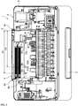
FIG. 1 is an overall perspective view illustrating the internal structure of a printer as viewed from above according to one or more embodiments of the present invention. -
FIG. 2 is a partially enlarged perspective view illustrating the structure of the mounting portion according to one or more embodiments of the present invention, as viewed from above. -
FIG. 3 is a perspective view illustrating the configuration of a substrate and a light emitter according to one or more embodiments of the present invention. -
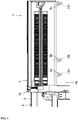
FIG. 4 is a cross-sectional view of the IV-IV line shown inFIG. 1 . -
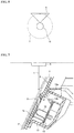
FIG. 5 is a schematic view illustrating the positional relationship between the range wherein light can be received by the light receiving part (circular region T) and the through hole according to one or more embodiments of the present invention. -
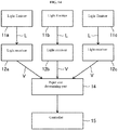
FIG. 6 is a block diagram illustrating a configuration of a printer according to one or more embodiments of the present invention. -
FIG. 7 is a view corresponding toFIG. 4 illustrating a variation of the printer according to one or more embodiments of the present invention. -
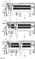
FIG. 8 is an overall perspective view illustrating the internal structure of a printer as viewed from above according to one or more embodiments of the present invention. -
FIG. 9 is a perspective view illustrating a configuration of the substrate, the light emitter, and the light receiver according to one or more embodiments of the present invention. -
FIG. 10 is a partially enlarged perspective view illustrating the movement of the medium guide according to one or more embodiments of the present invention, as viewed from above. -
FIG. 11 is a cross-sectional view of the XI-XI line shown inFIG. 8 . -
FIG. 12 is a view corresponding toFIG. 11 illustrating a state in which the medium guide overlaps the through hole according to one or more embodiments of the present invention. -
FIG. 13 is a circuit diagram illustrating the connected state of the light emitter and the light receiver according to one or more embodiments of the present invention. -
FIG. 14 is a block diagram illustrating a configuration of a printer according to one or more embodiments of the present invention. -
FIG. 15 is a view corresponding toFIG. 11 illustrating a variation of the printer according to one or more embodiments of the present invention. -
FIG. 16 is an overall perspective view of the internal structure of a printer as viewed from above according to one or more embodiments of the present invention. -
FIG. 17 is a partially enlarged perspective view illustrating the structure of the mounting portion according to one or more embodiments of the present invention, as viewed from above. -
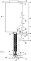
FIG. 18 is a schematic diagram illustrating the relationship between the light emitter and the light receiver, and the light refractor according to one or more embodiments of the present invention. -
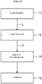
FIG. 19 is a block diagram illustrating a configuration of a printer according to one or more embodiments of the present invention. - Embodiments of the present invention will be described in detail below based on drawings. The following description of each embodiment is only an example, and is not intended to limit the present invention, its application, or its use. In embodiments of the invention, numerous specific details are set forth in order to provide a more thorough understanding of the invention. However, it will be apparent to one of ordinary skill in the art that the invention may be practiced without these specific details. In other instances, well-known features have not been described in detail to avoid obscuring the invention.
-
FIG. 1 illustrates aprinter 1 according to one or more embodiments of the present invention. Theprinter 1 is an embodiment of the imaging formation device, and is applied, for example, as an inkjet printer. Note that in theprinter 1 according to each embodiment described below, the position of amounting portion 4 described later is set to the rear side of ahousing 3 and the position of anejection portion 5 is set to the front side (front surface side) of thehousing 3. Then, the horizontal direction orthogonal to the front and rear direction is the left and right direction, and the vertical direction orthogonal to the front and rear direction as well as the left and right direction is the up and down direction. - The
printer 1 is equipped with adevice body 2. Thedevice body 2 has aresin housing 3, and amounting portion 4 for mounting a paper as the recording medium is provided on the rear side of thehousing 3 corresponding to various sizes. For example, themounting portion 4 has amounting surface 4a for mounting the paper of various sizes diagonally above. As illustrated inFIG. 1 , themounting surface 4a is formed in a range from aleft side portion 4b to aright side portion 4c of themounting portion 4. Furthermore, as illustrated inFIG. 4 , themounting surface 4a is inclined only at a predetermined angle (30° in the illustrated example) from the vertical direction so that the upper side faces the rear side of thehousing 3. Then, theright side portion 4c of themounting portion 4 is set as a reference position E (seeFIG. 1 ), and each paper is mounted on themounting surface 4a in a state where the side portions of each paper are aligned with the reference position E. - The
ejection portion 5 is provided on the front side in thehousing 3 to eject the paper fed from themounting portion 4 into thehousing 3. The paper mounted on themounting surface 4a of themounting portion 4 is sent to theejection portion 5 along a transporting direction orthogonal to the width direction of thehousing 3 using a feeding mechanism (not illustrated) provided in thehousing 3. - Furthermore, the
device body 2 is equipped with acartridge 6 having a nozzle (not illustrated) for discharging ink, and a carriage 7 on which thecartridge 6 is mounted. The carriage 7 is configured to be able to reciprocate in the left and right direction in thehousing 3. An image or the like is printed on a paper fed from themounting portion 4 into thehousing 3 by discharging ink from the nozzle of thecartridge 6 while reciprocating the carriage 7 in the left and right direction within thehousing 3. - Next, as illustrated in
FIG. 1 ,FIG. 2 , andFIG. 4 , a plurality (three in the illustrated example) of through holes 8 (8a, 8b, 8c) for passing through the mountingportion 4 are provided in the mountingportion 4. As illustrated inFIG. 5 , the opening of each throughhole 8 is formed in substantially a triangular shape so as to taper in the transporting direction. For example, the opening of each throughhole 8 is formed in a right angle isosceles triangle in which the lower vertex angle is a right angle. Furthermore, as illustrated inFIG. 4 , each throughhole 8 is formed to pass through from the mountingsurface 4a to each light receivingpart 12 described later. - The through
holes housing 3 so as to correspond to each paper size mounted in the mountingportion 4. For example, as illustrated inFIG. 1 , the throughhole 8 a formed near theleft side portion 4b of the mountingportion 4 is disposed so that the center of the left and right width thereof is positioned at a position separated from the reference position E only by the dimension X1. Furthermore, the throughhole 8b formed second from the left side is disposed so that the center of the left and right width thereof is positioned at a position separated from the reference position E only by a dimension X2. The throughhole 8c formed near theright side portion 4c of the mountingportion 4 is provided to detect the presence and absence of a paper mounted in the mountingportion 4. - Here, the dimension X1 corresponds to a length (297 mm) in the longitudinal direction in an A4 sized paper horizontally placed on the mounting
surface 4a of the mountingportion 4, or a length (279.4 mm) in the longitudinal direction in a letter size paper. Furthermore, the dimension X2 corresponds to a length (257 mm) in the longitudinal direction in a B5 size paper horizontally placed on the mountingsurface 4a of the mountingportion 4. - Furthermore, as illustrated in
FIG. 1 ,FIG. 2 , andFIG. 4 , a plurality (three in the illustrated example) of a light receiving part 12 (12a, 12b, and 12c) is disposed in a position corresponding to the position of each throughhole 8. Eachlight receiving part 12 is stored in astorage space 13a in astorage space 13 described later. Furthermore, eachlight receiving part 12 is composed of, for example, a phototransistor for visible light. The light incident on the phototransistor is converted into a voltage in the phototransistor. The voltage is input in an AD converter (not illustrated) via an integrated circuit (not illustrated) in thedevice body 2, and is converted to a digital value using the AD converter. Then, the digital value is output to asize determining part 14 described later. - Here, as illustrated in
FIG. 4 , in theprinter 1 according to the present embodiment, an illumination light or the like installed on the outside of the housing 3 (for example, indoors) is used as the light source S, and the light output from the illumination light becomes the light L incident on each light receivingpart 12. - As illustrated in
FIG. 3 , eachlight receiving part 12 is provided on arectangular substrate 10. For example, the plurality of light receivingpart substrate 10 in a state rising in a direction orthogonal to thesubstrate 10 surface. - As illustrated in
FIG. 4 , thestorage space 13 having apredetermined storage space 13a is provided on the opposite side of the mountingsurface 4a of the mountingportion 4. Thestorage space 13 and thestorage space 13a is formed so as to extend in the width direction of thehousing 3. Asupport portion 13b protruding into thestorage space 13a is integrally formed in thestorage space 13, and thesubstrate 10 is fixed to thesupport portion 13b. - As a characteristic of the
printer 1 according to the present embodiment, each throughhole 8 is disposed at a position shifted more upward than the position of each light receivingpart 12 in the transporting direction of the paper P along the mountingsurface 4a of the mountingportion 4. In other words, as illustrated inFIG. 2 andFIG. 4 , eachlight receiving part 12 is stored in thestorage space 13a of thestorage space 13 in a state hidden behind the mountingportion 4 as viewed from the front surface side of thehousing 3. Furthermore, as illustrated inFIG. 5 , a circular region T indicated by a virtual line represents a standard region in which light can be received by thelight receiving part 12, and each throughhole 8 is disposed corresponding to each light receivingpart 12 so that the opening is partially included in the circular region T. - Due to the positional relationship between the through
holes 8 and thelight receiving parts 12, in a state in which there is no paper P in the mountingportion 4, the light L output from the light source S passes through the throughhole 8 and is incident on each light receivingpart 12 so as to be along an inclined direction inclined upward by only a predetermined angle with respect to the protruding direction of the light receiving part 12 (seeFIG. 4 ). - Furthermore, as described above, because the through
hole 8 is disposed at a position shifted upward from the position of thelight receiving part 12, as indicated by the virtual line inFIG. 4 , the light L passes through a region more narrow than the actual opening in the throughhole 8 and incident in thelight receiving part 12. That is, the incident angle of the light L when incident on thelight receiving part 12 is limited by the positional relationship of the throughhole 8 and thelight receiving part 12, and the light L incident on thelight receiving part 12 is narrowed. Thus, the light L slightly attenuates as it passes through the throughhole 8. Then, the amount of light L is slightly smaller than the amount of light immediately after being output from the light source S to being incident on thelight receiving part 12 from the throughhole 8. However, because the opening of the throughhole 8 as described above is partially included in the circular region T, even when thelight receiving part 12 is hidden behind the mountingportion 4, the light L passing through the throughhole 8 is directly incident on thelight receiving part 12. - Meanwhile, as illustrated in
FIG. 4 , in a state in which there is a paper P on the mountingportion 4, the light L passes through the paper P so as to be inclined with respect to the thickness direction, and the light L is significantly attenuated in the process. For example, due to the throughhole 8 being disposed in a state shifted from thelight receiving part 12, the light L incident on thelight receiving part 12 is narrowed down in the throughhole 8, and for example, compared to a state in which the position of the throughhole 8 is aligned with thelight receiving part 12, and the light L passes through in the vertical direction with respect to the paper P on the mountingsurface 4a, it can be secured for a longer distance (attenuation distance) until the light L is incident on thelight receiving part 12. Then, due to the paper P and the throughhole 8 mounted on the mountingsurface 4a the amount of light L incident on thelight receiving part 12 significantly attenuates more than the light amount when output from the light source S. As a result, there is an amount of light L smaller than when no paper P is on the mountingportion 4 is incident on light receivingpart 12 in a position in which the thoughhole 8 is blocked by the paper P. - Then, as illustrated in
FIG. 6 , theprinter 1 has asize determining part 14 for determining the size of each paper mounted on the mountingportion 4 based on the amount of light incident on thelight receiving part 12, and the number and position of light receivingpart 12 on which the light L is incident. For example, the aspect for determining various sizes of paper are as follows. - In the
size determining part 14, when an output voltage (hereinafter "output voltage V1") is detected corresponding to when the amount of light L attenuated from all of thelight receiving part size determining part 14 determines that an A4 size paper or a letter size paper is mounted on the mountingportion 4 in a horizontal state. - In the
size determining part 14, when an output voltage (hereinafter "output voltage V2") is detected corresponding to when the amount of light L not attenuated from only light receivingpart 12a is incident (that is, the light L guided from the throughhole 8a to the directlight receiving part 12a without passing through the paper P), and when the output voltage V1 from the otherlight receiving part size determining part 14 determines that a B5 size paper is mounted on the mountingportion 4 in a horizontal state. - In the
size determining part 14, when the output voltage V2 from bothlight receiving part light receiving part 12c is detected, thesize determining part 14, for example, determines that a postcard size paper, paper less than or equal to B5 size, envelope, L size, and the like is mounted in the mountingportion 4. - In the
size determining part 14, when the output voltage V2 is detected from all of thelight receiving part size determining part 14 determines that no paper of any size is mounted on the mountingportion 4. - Then, as illustrated in
FIG. 6 , thesize determining part 14 sends each determination result to acontroller 15 composed of a CPU provided in thedevice body 2. Thecontroller 15 operates each mechanism such as the carriage 7 and the like based on the determination results. In one or more embodiments of the invention, the papersize determining part 14 may be implemented in software that is performed by thecontroller 15 or the CPU thereof. - As described above, the through
hole 8 is configured so that the path of the light L incident on thelight receiving part 12 is narrowed in advance. Then, as described above, in a state in which there is paper P on the mountingportion 4, the amount of light L output from the light source S is significantly attenuated by the paper P and the thoughhole 8, and the amount of light L smaller than the state in which no paper P is on the mountingportion 4 is incident on thelight receiving part 12. As a result, it is possible to reliably distinguish the amount of light L incident on thelight receiving part 12 based on the paper P mounted on the mountingportion 4. That is, the throughhole 8 is provided between the light receivingpart 12 and the light source S, and functions as a change portion (light adjuster) for changing the amount of light L when the light L from the light source S is incident on thelight receiving part 12 based on the presence and absence of paper P on the mountingportion 4. - Therefore, in the
printer 1 according to this embodiment, it is possible to change the amount of light when the light L from the light source S is incident on thelight receiving part 12 based on the paper P on the mountingportion 4, and reliably and appropriately determine the paper size so that erroneous detection does not occur. - Furthermore, in the
printer 1 according to this embodiment, by providing a throughhole 8 passing through from the mountingsurface 4a of the mountingportion 4 to thelight receiving part 12, the mechanism for detecting the paper size equipped with a change portion (light adjuster) can be simplified, and the cost of the device body in theprinter 1 can be reduced. - Furthermore, because the
storage space 13 having astorage space 13a for storing thelight receiving part 12 is provided on the opposite side of the mountingsurface 4a in the mountingportion 4, the light L guided from the throughhole 8 can be effectively caused to be incident on thelight receiving part 12. - Furthermore, because the opening in each through
hole 8 is formed in substantially a triangular shape so as to taper toward the transporting direction, when setting the paper P on the mounting portion 4 (mountingsurface 4a) along the transporting direction, the lower end portion of the paper P does not catch on each throughhole 8, and the paper P can be smoothly mounted on the mounting portion 4 (mountingsurface 4a). - Furthermore, in the
printer 1 according to this embodiment, because an illumination light and the like on the outside of thehousing 3 is used as the light source S, it is unnecessary to additionally provide a dedicated light emitter composed of an LED as the light source S, and the mechanism for detecting the paper size can be simplified, thus reducing the cost of the device body in theprinter 1. -
FIG. 7 illustrates a variation of example 1. Note that in the following variation and the description of the embodiments, the same portions inFIG. 1 through 6 will be denoted by the same reference numerals, and a detailed description thereof will be omitted. - As illustrated in
FIG. 7 , each throughhole 8 is formed at an incline with respect to the mountingsurface 4a so as to pass through from the mountingsurface 4a on the mountingportion 4 to each light receivingpart 12. By providing the throughhole 8 as such, the light L passing through along the hole direction of the throughhole 8 can be caused to be more efficiently incident on each light receivingpart 12. - In particular, the through
hole 8 in the variation is configured to incline only at a predetermined angle θ (θ=30° in the illustrated example) with respect to the mountingsurface 4a. Thus, for example, compared to the throughhole 8 in which the angle θ is formed to be 90° (that is, a state formed to pass through in the vertical direction with respect to the mountingsurface 4a), the distance from the paper P to each light receivingpart 12 is approximately doubled, and the attenuation distance of the light L can be secured to a longer distance. As a result, the amount of light L incident on thelight receiving part 12 can more reliably be distinguished based on the presence and absence of paper P mounted on the mountingportion 4. Note that the angle θ in this variation is set to 30°, but it is not limited to this angle, and may be set to an angle less than 90°. - In the
printer 1 according to this embodiment, an aspect using the throughhole 8 as the change portion (light adjuster) is illustrated, but it is not limited to this. For example, it may be a light adjuster in which each throughhole 8 is blocked by a transparent member such as a transparent glass member, acrylic member, and the like. In this case, the opening of each throughhole 8 is not limited to the substantially triangular shape as described above, and may be formed in a polygonal shape including a square shape, or a circular shape. That is, the change portion (light adjuster) is provided between the light receivingpart 12 and the light source S, and may function for changing the amount of light when the light L from the light source S is incident on thelight receiving part 12 based on the presence and absence of paper P on the mountingportion 4. -
FIG. 8 through 14 illustrate theprinter 1 according to one or more embodiments of the present invention. In this embodiment, compared to example 1, the specific configuration differs in the light source, the through hole, and the change portion. Note that in the following description, the same portions inFIG. 1 through 7 will be denoted by the same reference numerals, and a detailed description thereof will be omitted. - In this embodiment, as illustrated in
FIG. 8 andFIG. 12 , a plurality (three in the illustrated example) of through holes 20 (20a, 20b, 20c) formed passing through in a substantially rectangular shape are provided in the mountingportion 4. The throughholes housing 3 in positions to correspond to each paper P size mounted in the mountingportion 4. - As illustrated in
FIG. 8 through 12 , in theprinter 1 according to this embodiment, a plurality (three in the illustrated example) of light receiving part 12 (12a, 12b, 12c) composed of a phototransistor are provided in thehousing 3. Furthermore, a plurality (three in the illustrated example) of light emitters 11 (11a, 11b, 11c) composed of an LED element are provided as the light source in thehousing 3, and the light output from the end portion of eachlight emitter 11 is the light L incident on the end portion of each light receivingpart 12. - For example, each
light emitter 11 and each light receivingpart 12 are disposed close to each other so as to form a pair on positions corresponding to the position of each throughhole 20 on the opposite side (back side) of the mountingsurface 4a on the mountingportion 4. As illustrated inFIG. 9 , eachlight emitter 11 and each light receivingpart 12 are placed at a predetermined interval on thesubstrate 10 along the longitudinal direction of thesubstrate 10 in a state raising in a vertical direction with respect to the back side of thesubstrate 10 and, for example, forming a pair vertically. Note that in this embodiment, thelight emitters light receiving part FIG. 11 and FIG. 12 , eachlight emitter 11 and each light receivingpart 12 are stored in thestorage space 13a in a state in which thesubstrate 10 is fixed to the supportingportion 13b of thestorage space 13. - As illustrated in
FIG. 13 , eachlight receiving part 12 is in a state of always being able to receive the light L output from the eachlight emitter 11, and when the light L is reflected, the reflected light L is incident on each adjacentlight receiving part 12. As illustrated inFIG. 14 , eachlight receiving part 12, similar to example 1, is configured so as to output a voltage corresponding to the amount of incident light L to thesize determining part 14. - As a characteristic of the
printer 1 according to this embodiment, as illustrated inFIG. 8 , theprinter 1 is equipped with amedium guide 21 that can move along the width direction of the mountingportion 4. As illustrated inFIG. 10 , themedium guide 21 stops at a position overlapping any one of the throughholes surface 4a on the mountingportion 4 in the stopped position. - Furthermore, as illustrated in
FIG. 12 , thereflective surface 22 is formed in themedium guide 21 on the side opposite the mountingsurface 4a on the mountingportion 4. Thereflective surface 22 is treated, for example, as a mirror surface so as to increase the reflectance of light. That is, thereflective surface 22 is configured so as to reflect the light L toward thelight receiving part 12 at a portion within the throughhole 20 when the throughhole 20 is blocked by overlapping any one of the throughholes medium guide 21. - The
size determining part 14 according to this embodiment is configured so as to determine the size of each paper P mounted on the mountingportion 4 based on the amount of light L to thelight receiving part 12 reflected by thereflective surface 22 on themedium guide 21. Furthermore, eachlight receiving part 12 is set so that themedium guide 21 does not overlap the throughhole 20, the output voltage is not the maximum value when the light L reflected by the paper P is incident, and the output voltage is the maximum value when the light L reflected by thereflective surface 22 of themedium guide 21 is incident due to themedium guide 21 overlapping the throughhole 20. The aspect for determining the specific size of each paper will be described below. - The
size determining part 14 determines that an A4 size or letter size paper P is mounted on the mountingportion 4 when thesize determining part 14 detects an output voltage of the maximum value from only thelight receiving part 12a and an output voltage less than the maximum value from the otherlight receiving part FIG. 10 , themedium guide 21 overlaps the throughhole 20a. - The
size determining part 14 determines that a B5 size paper P is mounted on the mountingportion 4 when thesize determining part 14 detects an output voltage of the maximum value from only thelight receiving part 12b and detects an output voltage less than the maximum value from only thelight receiving part 12c. In this case, as illustrated inFIG. 10 , themedium guide 21 overlaps the throughhole 20b. - The
size determining part 14 determines that a postcard size paper P is mounted on the mountingportion 4 when thesize determining part 14 detects an output voltage less than the maximum value from only thelight receiving part 12c, and does not detect an output voltage from the otherlight receiving part FIG. 10 , themedium guide 21 is positioned between the throughhole 20b and the throughhole 20c. - Note that the
size determining part 14 determines that no paper P of any size is mounted on the mountingportion 4 when an output voltage is not detected from thelight receiving part 12c. - Then, as illustrated in
FIG. 14 , thesize determining part 14 sends each determination result to thecontroller 15. Thecontroller 15 operates each mechanism such as the carriage 7 and the like based on the determination results. - The other configurations of the
printer 1 in example 2 are similar to the configurations of theprinter 1 according to example 1. - As described above, the medium guide 21 (reflective surface 22) in this embodiment is interposed between the light receiving
part 12 and thelight emitter 11, and functions as the change portion for changing the amount of light L based on the paper P on the mountingportion 4 when the light L from thelight emitter 11 is incident on thelight receiving potion 12. Then, in theprinter 1 according to this embodiment, the position of each paper P mounted on the mountingsurface 4a on the mountingportion 4 can easily be aligned using themedium guide 21, and the amount of light can be changed when the light L from eachlight emitter 11 is incident on thelight receiving part 12 based on the paper P on the mountingportion 4 by using the medium guide 21 (reflective surface 22) correlating to the change portion. Therefore, in theprinter 1 according to this embodiment, the paper size can also be reliably and appropriately determined. - Furthermore, the
light receiving part 12 is set so that the output voltage is the maximum voltage when the light L reflected by thereflective surface 22 on themedium guide 21 is incident by themedium guide 21 overlapping the throughhole 20. Therefore, the difference between the output voltage having the maximum value and the output voltage from thelight receiving part 12 when the light L reflected on the rear surface of the paper P in the throughhole 20 is incident by themedium guide 21 not overlapping the throughhole 20 appears large. Due to this voltage difference, both output voltages can be reliably distinguished, and erroneous detection of the paper size by thesize determining part 14 can be prevented in advance. -
FIG. 15 illustrates a variation of the example 2. Note that in the following description, the same portions inFIG. 7 through 14 will be denoted by the same reference numerals, and a detailed description thereof will be omitted. - In this variation, as illustrated in
FIG. 15 , for eachlight emitter 11 and each light receivingpart 12, eachlight receiving part 12 is disposed on the upper side while eachlight emitter 11 is disposed on the lower side. Furthermore, a plurality ofslits 23 are provided in the mountingportion 4. For example, theslits 23 are formed to pass through a horizontally elongated hole at the position of each throughhole 20 opposing each light receivingpart 12 and disposed at intervals in the vertical direction. The other configurations of theprinter 1 according to this variation are similar to the configuration of theprinter 1 according to example 2. - By providing
such slits 23, it is possible to shield the light from outside the housing 3 (for example, light output from an interior illumination light) in front of each light receivingpart 12 so to not be incident on each light receivingpart 12. As a result, when there is no paper on the mountingsurface 4a on the mountingportion 4, light from the outside of thehousing 3 being incident on thelight receiving part 12 is prevented, and it is possible to reliably determine that there is no paper on the mountingsurface 4a of the mountingportion 4 by thesize determining part 14. -
FIG. 16 through 19 illustrate theprinter 1 according to one or more embodiments of the present invention. In this embodiment, the specific configuration of the light emitter, light receiving part, and change portion differs compared to example 2. Furthermore, in theprinter 1 according to one or more embodiments of the present invention, throughholes 20 as in example 2 are not provided. Note that in the following description, the same portions inFIG. 8 through 14 will be denoted by the same reference numerals, and a detailed description thereof will be omitted. - In the
printer 1 according to this embodiment, onelight emitter 11 composed of an LED element provided in thehousing 3 is used as the light source. As illustrated inFIG. 16 through 18 , thelight emitter 11 is provided at one end portion in the width direction of the mountingportion 4. For example, a substantially plate-shapedfirst attachment plate 31 extending in the front and back direction is fixed to, for example, aleft side portion 4b on the mountingportion 4, and thelight emitter 11 is attached to, for example, a right side surface of thefirst attachment plate 31 so as to output the light L (seeFIG. 18 ) towards the right direction (inner side in the width direction of the housing 3). - Furthermore, the
light receiving part 12 is provided opposite to thelight emitter 11 in the left and right direction on the other end portion in the width direction of the mountingportion 4. For example, a substantially plate-shapedsecond attachment plate 32 extending in the front and back direction is fixed to aright side portion 4c on the mountingportion 4, and thelight receiving part 12 is attached to, for example, a left side surface of thesecond attachment plate 32 so as to face the left and right direction, that is, towards thelight emitter 11 side. Thelight receiving part 12 is composed of a phototransistor, similar to example 2. Then, thelight emitter 11 and thelight receiving part 12 are disposed so as to be positioned on the same straight line M in a position at the same height, and the light L output from thelight emitter 11 is incident on thelight receiving part 12. - As illustrated in
FIG. 16 to FIG. 18 , theprinter 1 is equipped with amedium guide 21 that can move along the width direction of the mounting portion 4 (direction of straight line M). Themedium guide 21, similar to example 2, is configured so as to regulate the position of each paper P with respect to the mountingportion 4 by holding the inner portion of each paper P mounted on the mountingsurface 4a on the mountingportion 4. Note that themedium guide 21 in this example, differing from example 2, does not have areflective surface 22 formed. - Furthermore, as a characteristic of the
printer 1 according to this embodiment, a substantially plate-shapedlight refractor 33 positioned on the straight line M connecting thelight emitter 11 and thelight receiving part 12 is fixed in the front end portion of themedium guide 21. Thelight refractor 33 refracts the light L output from thelight emitter 11 and incident on thelight receiving part 12 in the middle, and is formed in a substantially rectangular shape as viewed from the side surface, composed of, for example, a transparent glass material or acrylic material. - In addition, as illustrated in
FIG. 18 , thelight refractor 33 has anincident surface 34 whereon the light L from thelight emitter 11 is incident and is orthogonal to the incident direction of the light L (that is, the direction of straight line M), and anemission surface 35 inclined at only a predetermined angle (10° in the illustrated example) with respect to theincident surface 34 and for emitting light L incident on theincident surface 34 to thelight receiving part 12. For example, theemission surface 35 is inclined so as to come closer to theincident surface 34 side (left side of the housing 3) facing the front side of thehousing 3. Due to such aninclined emission surface 35, thelight refractor 33 is configured so as to cause the light L output from thelight emitter 11 towards thelight receiving part 12 to be incident on thelight receiving part 12 by refracting toward the front side of thehousing 3 only at a predetermined angle with respect to the straight line M direction. - In the
printer 1 according to this embodiment, the refractive position of the light L from thelight refractor 33 on the straight line M is changed according to the position of themedium guide 21, and changes the amount of light L incident on thelight receiving part 12. Then, the size determining part 14 (seeFIG. 19 ) is configured to determine the size of each paper P mounted on the mountingportion 4 based on the change in amount of light L incident on thelight receiving part 12 corresponding to the position ofthemedium guide 21. The aspect for determining the specific size of each paper P is as follows. - As illustrated in
FIG. 18 , when the position of themedium guide 21 is aligned with the maximum size paper P mounted on the mountingportion 4, themedium guide 21 is in a state separated from thelight receiving part 12 as much as possible (the lightreactive portion 33 is positioned at point A). In this state, the distance in the front and back direction between the light L refracted by thelight refractor 33 and thelight receiving part 12 is a maximum. Then, the amount of light L incident on thelight receiving part 12 is a minimum, and the value of the voltage output from thelight receiving part 12 is a minimum. Thus, when thesize determining part 14 detects a minimum output voltage, thesize determining part 14 determines that the maximum size (for example, letter size) paper P is mounted on the mountingportion 4. - Meanwhile, when the position of the
medium guide 21 is aligned with the minimum size paper P mounted on the mountingportion 4, themedium guide 21 is in a state as close to thelight receiving part 12 as possible (the lightreactive portion 33 is positioned at point D). In this state, the distance in the front and back direction between the light L refracted by thelight refractor 33 and thelight receiving part 12 is a minimum. Then, the amount of light L incident on thelight receiving part 12 is a maximum, and the value of the voltage output from thelight receiving part 12 is maximum. Thus, when thesize determining part 14 detects a maximum output voltage, thesize determining part 14 determines that the minimum size (for example, postcard size) paper P is mounted on the mountingportion 4. - Furthermore, when the position of the
medium guide 21 is aligned with vertically placed A4 sized paper P mounted on the mountingportion 4, and when thelight refractor 33 is positioned at point B separated at only a predetermined distance from reference position E, the voltage value output from thelight receiving part 12 becomes a predetermined voltage value due to the change in distance in front and back direction between the light L refracted by thelight refractor 33 and thelight receiving part 12. In addition, when the position of themedium guide 21 is aligned with the vertically placed B5 sized paper P mounted on the mountingportion 4, and when thelight refractor 33 is positioned at point C separated only a predetermined distance from the reference point E, a voltage larger than in the case of the A4 size is output from thelight receiving part 12. Thus, thesize determining part 14 determines the size of each paper P mounted on the mountingportion 4 by the voltage value output from thelight receiving part 12. - Note that in
FIG. 17 , a state is illustrated in which the position of themedium guide 21 is aligned with a vertically placed A4 sized paper P mounted on the mountingportion 4. - Then, as illustrated in
FIG. 19 , thesize determining part 14 sends each determination result to thecontroller 15. Thecontroller 15 operates each mechanism such as the carriage 7 and the like based on the determination results. - As described above, the
light refractor 33 is provided between thelight emitter 11 and thelight receiving part 12, and functions as a change portion that changes the amount of light based on the paper P on the mountingportion 4 when the light L from thelight emitter 11 is incident on thelight receiving part 12. Then, in theprinter 1 according to this embodiment, it is possible to easily align the position of each paper P mounted on the mountingsurface 4a on the mountingportion 4 using themedium guide 21. Along with that, due to the light refractor 33 (change portion) moving along with themedium guide 21, because the amount of light L incident on thelight receiving part 12 changes based on the paper P on the mountingportion 4, the paper size can be reliably and easily determined. Furthermore, in theprinter 1 according to this embodiment, because it may be configured to provide the one of thelight emitters 11 and thelight receiving part 12, the mechanism for detecting the paper size can be simplified, and cost of the entire device body in theprinter 1 can be reduced. - Furthermore, in the
light refractor 33, the light L output from thelight emitter 11 is incident on theincident surface 34 and passes through the inside of thelight refractor 33 along the direction of the straight line M. Meanwhile, the light L passing through the inside of thelight refractor 33 is refracted toward the front side of thehousing 3 by theemission surface 35 at only a predetermined angle with respect to the direction of the straight line M. In addition, thelight refractor 33 is integrally provided with themedium guide 21, and is configured so as to move along the straight line M along with themedium guide 21. Therefore, due to themedium guide 21 being caused to move, while maintaining an angle of theincident surface 34 and theemission surface 35 with respect to the straight line M, it is possible for the light refractor 33 (incident surface 34 and emission surface 35) to move closer to or separate farther from thelight receiving part 12. Meanwhile, when the light L is refracted by theemission surface 35 at a position where the light refractingportion 33 is separated far from the light receiving part 12 (for example, position of point A illustrated inFIG. 18 ), the amount of light L incident on thelight receiving part 12 decreases. Meanwhile, when the light L is refracted by theemission surface 35 at a position where the light refractingportion 33 is close to the light receiving part 12 (for example, position of point D illustrated inFIG. 18 ), the amount of light L incident on thelight receiving part 12 increases. Thus, the amount of light L incident on thelight receiving part 12 corresponding to the position of thelight refractor 33 can be changed. - Furthermore, the
light receiving part 12 is composed of a phototransistor, and outputs a predetermined voltage value corresponding to the amount of input light. Then, when the position of themedium guide 21 is aligned with the minimum sized paper P mounted on the mountingportion 4, themedium guide 21 is as close as possible to thelight receiving part 12. Therefore, when the position of themedium guide 21 is aligned with the minimum size paper P, the amount of light L incident on thelight receiving part 12 by being refracted by thelight refractor 33 is a maximum. That is, the voltage output from thelight receiving part 12 is a maximum. By such a configuration, when the position of themedium guide 21 is aligned with the minimum size paper P mounted on the mountingportion 4, thesize determining part 14 can determine the size of each paper P mounted on the mountingportion 4 using the voltage output from thelight receiving part 12 as a reference. - In this embodiment, an aspect is illustrated where one
light emitter 11 composed of an LED element is used as the light source, but it is not limited to this. That is, as described in the first example described above, an illumination light and the like mounted on the outside of thehousing 3 may be used as the light source. - In each of the embodiments described above, an example is given of the
printer 1, which is one embodiment for the image forming apparatus, but it is not limited to this. For example, one or more embodiments of the present invention may be applied to an image forming apparatus such as a compound device integrally combined with a scanner or printer function, and the like. - Embodiments for the present invention are described above, but the present invention is not limited to the above embodiments, and can have various variations within the scope of the invention defined in the appended claims. For instance, according to one or more embodiments, the image forming apparatus may be provided with a one light receiver comprising a phototransistor that outputs a voltage to a controller, the phototransistor outputting the voltage that increases as the medium guide approaches the one light receiver.
- Although the disclosure has been described with respect to only a limited number of embodiments, those skilled in the art, having benefit of this disclosure, will appreciate that various other embodiments may be devised without departing from the scope of the present invention. Accordingly, the scope of the invention should be limited only by the attached claims.
- One or more embodiments of the present invention is industrially applicable, for example, as an inkjet printer.
-
- 1:
- Printer
- 2:
- Device Body
- 3:
- Housing
- 4:
- Mounting Portion
- 4a:
- Mounting Surface
- 8, 20:
- Through Hole
- 11:
- Light emitter
- 12:
- Light Receiving Part
- 13:
- Storage space
- 13a:
- Storage Space
- 14:
- Size Determining Part
- 15:
- Controller
- 21:
- Medium guide
- 22:
- Reflective Surface
- 23:
- Slit
- 33:
- Light refractor
- 34:
- Incident Surface
- 35:
- Emission Surface
- L:
- Light
- P:
- Paper
- S:
- Light Source
Claims (15)
- An image forming apparatus, comprising:a housing (3);a mounting portion (4) in the housing (3) that is configured to hold a recording medium;one or more light receivers (12) in the housing;a light adjuster that adjusts an amount of light incident on the light receivers (12) based on presence or size of the recording medium on the mounting portion (4); anda controller (15) that determines a size of the recording medium based on the amount of light (L) that has been adjusted by the light adjuster.
- The image forming apparatus according to claim 1,wherein the mounting portion (4) comprises a mounting surface (4a) in contact with the recording medium,wherein the light receivers (12) are arranged in a width direction of the housing (3), between the housing (3) and the mounting surface (4a), andwherein the light adjuster comprises a through hole (8, 20) that guides light passing through the recording medium in an inclined direction to each of the light receivers (12).
- The image forming apparatus according to claim 2, wherein the through hole (8,20) is provided at a position on the mounting portion (4) shifted from a center of each of the light receivers (12).
- The image forming apparatus according to claim 2 or 3, wherein the housing (3) comprises a storage space (13a) that stores each ofthe light receivers (12), on the opposite side ofthe mounting surface (4a) on the mounting portion (4).
- The image forming apparatus according to any claim from 2 to 4, wherein the through hole (8,20) is formed through the mounting portion (4) from the mounting surface (4a) to each of the light receivers (12).
- The image forming apparatus according to any claim from 2 to 5, wherein an opening of the through hole (8, 20) tapers toward a transporting direction of the recording medium on the mounting surface (4a).
- The image forming apparatus according to any claim from 2 to 6, wherein the through hole (8,20) is formed at an acute angle with respect to a vertical direction of the mounting surface (4a).
- The image forming apparatus according to any claim from 2 to 7, wherein each of the light receivers (12) comprises a phototransistor that receives the light (L) from a light source (S) installed outside the housing (3).
- The image forming apparatus according to claim 1, further comprising:one or more light emitters (11) in the housing (3),wherein the mounting portion (4) comprises:a mounting surface (4a) in contact with the recording medium; andone or more through holes (8, 20) formed through the mounting portion (4) at positions each corresponding to a potential size of the recording medium,wherein the light emitters (11) are disposed, together with the light receivers (12), at positions of the through holes (8, 20) between the housing (3) and the mounting surface (4a), respectively,wherein the light adjuster comprises a medium guide (21) that moves along a width direction of the mounting portion (4) and holds a position of the recording medium in contact with an end portion of the recording medium at a position where the medium guide (21) overlaps each of the through holes (8, 20); andwherein the medium guide (21) comprises a reflective surface (22) that reflects the light (L) from each of the light emitters (11) when the medium guide (21) overlaps with the each of the light emitters (11).
- The image forming apparatus according to claim 9, wherein the housing (3) comprises a storage space (13a) that stores each of the light receivers (12), on the opposite side of the mounting surface (4a).
- The image forming apparatus according to claim 9 or 10, wherein an opening of each of the through holes (8, 20) tapers toward a transporting direction of the recording medium.
- The image forming apparatus according to any claim from 9 to 11,wherein each of the light receivers (12) comprises a phototransistor that outputs a voltage to the controller (15); andwherein a first voltage output when the medium guide overlaps the through hole (8, 20) corresponding to each of the light receivers (12) is higher than a second voltage output when the recording medium overlaps the through hole (8, 20) corresponding to the each ofthe light receivers (12).
- The image forming apparatus according to any claim from 9 to 12, wherein a slit (23) is provided in each of the through holes (8, 20).
- The image forming apparatus according to claim 1, further comprisinga medium guide (21) that moves along a width direction of the mounting portion (4) and holds a position of the recording medium in contact with an end portion of the recording medium,wherein the image forming apparatus comprises one light receiver (12), and the one light receiver (12) is disposed at one end portion of the mounting portion (4) in the width direction,wherein the light adjuster comprises a light refractor (33) that moves on a straight line connecting another end portion of the mounting portion (4) to the one light receiver (12) and refracts light (L) output from a light emitter (11) at a predetermined angle with respect to the direction of the straight line, andwherein the light refractor (33) refracts the light (L) output from the light emitter (11) away from the one light receiver (12) as the light refractor (33) approaches the other end portion.
- The image forming apparatus according to claim 14,wherein the light refractor (33) comprisesan incident surface (34) on which the light (L) output from the light emitter (11) is orthogonally incident; andan emission surface (35) inclined at a predetermined angle with respect to the incident surface (34), for emitting light (L) incident on the incident surface (34).
Applications Claiming Priority (1)
| Application Number | Priority Date | Filing Date | Title |
|---|---|---|---|
| JP2016160495A JP2018027837A (en) | 2016-08-18 | 2016-08-18 | Image formation device |
Publications (1)
| Publication Number | Publication Date |
|---|---|
| EP3284604A1 true EP3284604A1 (en) | 2018-02-21 |
Family
ID=59649602
Family Applications (1)
| Application Number | Title | Priority Date | Filing Date |
|---|---|---|---|
| EP17186667.6A Withdrawn EP3284604A1 (en) | 2016-08-18 | 2017-08-17 | Image forming apparatus |
Country Status (4)
| Country | Link |
|---|---|
| US (1) | US20180052412A1 (en) |
| EP (1) | EP3284604A1 (en) |
| JP (1) | JP2018027837A (en) |
| CN (1) | CN107757123A (en) |
Citations (5)
| Publication number | Priority date | Publication date | Assignee | Title |
|---|---|---|---|---|
| JP2001322723A (en) | 2000-05-15 | 2001-11-20 | Ricoh Co Ltd | Paper size detection device and image forming device |
| US20070201918A1 (en) * | 2006-02-28 | 2007-08-30 | Kabushiki Kaisha Toshiba | Image copier and image copying method |
| US20080181624A1 (en) * | 2006-08-08 | 2008-07-31 | Takanori Yamada | Document original size detecting device |
| US20110076080A1 (en) * | 2009-09-25 | 2011-03-31 | Brother Kogyo Kabushiki Kaisha | Image recording apparatus |
| JP2011254216A (en) | 2010-06-01 | 2011-12-15 | Ricoh Co Ltd | Automatic document feeder, image reader, and image forming device |
Family Cites Families (2)
| Publication number | Priority date | Publication date | Assignee | Title |
|---|---|---|---|---|
| CN1028917C (en) * | 1987-09-08 | 1995-06-14 | 夏普公司 | Original size detection device for copying equipment |
| JPH06194910A (en) * | 1992-12-24 | 1994-07-15 | Fuji Xerox Co Ltd | Paper size detector |
-
2016
- 2016-08-18 JP JP2016160495A patent/JP2018027837A/en active Pending
-
2017
- 2017-07-12 US US15/647,376 patent/US20180052412A1/en not_active Abandoned
- 2017-08-03 CN CN201710656063.6A patent/CN107757123A/en active Pending
- 2017-08-17 EP EP17186667.6A patent/EP3284604A1/en not_active Withdrawn
Patent Citations (5)
| Publication number | Priority date | Publication date | Assignee | Title |
|---|---|---|---|---|
| JP2001322723A (en) | 2000-05-15 | 2001-11-20 | Ricoh Co Ltd | Paper size detection device and image forming device |
| US20070201918A1 (en) * | 2006-02-28 | 2007-08-30 | Kabushiki Kaisha Toshiba | Image copier and image copying method |
| US20080181624A1 (en) * | 2006-08-08 | 2008-07-31 | Takanori Yamada | Document original size detecting device |
| US20110076080A1 (en) * | 2009-09-25 | 2011-03-31 | Brother Kogyo Kabushiki Kaisha | Image recording apparatus |
| JP2011254216A (en) | 2010-06-01 | 2011-12-15 | Ricoh Co Ltd | Automatic document feeder, image reader, and image forming device |
Also Published As
| Publication number | Publication date |
|---|---|
| CN107757123A (en) | 2018-03-06 |
| US20180052412A1 (en) | 2018-02-22 |
| JP2018027837A (en) | 2018-02-22 |
Similar Documents
| Publication | Publication Date | Title |
|---|---|---|
| JP4765564B2 (en) | Print media transport tray | |
| US11572246B2 (en) | Document conveying apparatus that properly discharges documents regardless of amount of documents | |
| US7654525B2 (en) | Reflective sheet detector | |
| CN113800287A (en) | Printer unit that can correct paper | |
| CN100380104C (en) | Reflective optical sensors, mounts and data processing equipment | |
| US9592982B2 (en) | Medium detection mechanism, medium detection method, and printing apparatus | |
| US8382229B2 (en) | Lead edge detector for printer | |
| US9438760B2 (en) | Scanner | |
| US20180052412A1 (en) | Image forming apparatus | |
| US9511936B2 (en) | Image reading apparatus | |
| KR20080016322A (en) | Paper size sensing device and image forming apparatus having same | |
| US10552726B2 (en) | Card-type medium counting mechanism, card-type medium housing device, and card housing device | |
| EP2670121B1 (en) | Image reader | |
| US7898674B2 (en) | Apparatus and method for detecting the position of media in a media path | |
| US20170339292A1 (en) | Image reading apparatus and image forming apparatus | |
| JP3723006B2 (en) | End face detection device | |
| US8395784B2 (en) | Method of lead edge detection in an inkjet printer | |
| JP2011254216A (en) | Automatic document feeder, image reader, and image forming device | |
| CN103376476B (en) | Flaky medium detecting device and laminated medium processing unit | |
| EP4498668A1 (en) | Optical device and document reading apparatus | |
| JP4670361B2 (en) | Printer | |
| JP2009166999A (en) | Paper flotation sensor | |
| WO2009082371A1 (en) | Color sensing device | |
| JP2012096449A (en) | Ink storage container | |
| US11273652B2 (en) | Sensor unit and image forming apparatus equipped with same |
Legal Events
| Date | Code | Title | Description |
|---|---|---|---|
| PUAI | Public reference made under article 153(3) epc to a published international application that has entered the european phase |
Free format text: ORIGINAL CODE: 0009012 |
|
| STAA | Information on the status of an ep patent application or granted ep patent |
Free format text: STATUS: THE APPLICATION HAS BEEN PUBLISHED |
|
| AK | Designated contracting states |
Kind code of ref document: A1 Designated state(s): AL AT BE BG CH CY CZ DE DK EE ES FI FR GB GR HR HU IE IS IT LI LT LU LV MC MK MT NL NO PL PT RO RS SE SI SK SM TR |
|
| AX | Request for extension of the european patent |
Extension state: BA ME |
|
| STAA | Information on the status of an ep patent application or granted ep patent |
Free format text: STATUS: THE APPLICATION IS DEEMED TO BE WITHDRAWN |
|
| 18D | Application deemed to be withdrawn |
Effective date: 20180822 |