EP3284511A1 - Elektrodenleitung, implantat und verfahren zur identifikation einer elektrodenleitung - Google Patents
Elektrodenleitung, implantat und verfahren zur identifikation einer elektrodenleitung Download PDFInfo
- Publication number
- EP3284511A1 EP3284511A1 EP16184298.4A EP16184298A EP3284511A1 EP 3284511 A1 EP3284511 A1 EP 3284511A1 EP 16184298 A EP16184298 A EP 16184298A EP 3284511 A1 EP3284511 A1 EP 3284511A1
- Authority
- EP
- European Patent Office
- Prior art keywords
- implant
- circuit
- electrode
- electrode line
- electrode lead
- Prior art date
- Legal status (The legal status is an assumption and is not a legal conclusion. Google has not performed a legal analysis and makes no representation as to the accuracy of the status listed.)
- Granted
Links
Images


Classifications
-
- A—HUMAN NECESSITIES
- A61—MEDICAL OR VETERINARY SCIENCE; HYGIENE
- A61N—ELECTROTHERAPY; MAGNETOTHERAPY; RADIATION THERAPY; ULTRASOUND THERAPY
- A61N1/00—Electrotherapy; Circuits therefor
- A61N1/02—Details
- A61N1/025—Digital circuitry features of electrotherapy devices, e.g. memory, clocks, processors
-
- A—HUMAN NECESSITIES
- A61—MEDICAL OR VETERINARY SCIENCE; HYGIENE
- A61B—DIAGNOSIS; SURGERY; IDENTIFICATION
- A61B5/00—Measuring for diagnostic purposes; Identification of persons
- A61B5/68—Arrangements of detecting, measuring or recording means, e.g. sensors, in relation to patient
- A61B5/6846—Arrangements of detecting, measuring or recording means, e.g. sensors, in relation to patient specially adapted to be brought in contact with an internal body part, i.e. invasive
- A61B5/6847—Arrangements of detecting, measuring or recording means, e.g. sensors, in relation to patient specially adapted to be brought in contact with an internal body part, i.e. invasive mounted on an invasive device
- A61B5/686—Permanently implanted devices, e.g. pacemakers, other stimulators, biochips
-
- A—HUMAN NECESSITIES
- A61—MEDICAL OR VETERINARY SCIENCE; HYGIENE
- A61N—ELECTROTHERAPY; MAGNETOTHERAPY; RADIATION THERAPY; ULTRASOUND THERAPY
- A61N1/00—Electrotherapy; Circuits therefor
- A61N1/02—Details
- A61N1/04—Electrodes
- A61N1/05—Electrodes for implantation or insertion into the body, e.g. heart electrode
-
- A—HUMAN NECESSITIES
- A61—MEDICAL OR VETERINARY SCIENCE; HYGIENE
- A61N—ELECTROTHERAPY; MAGNETOTHERAPY; RADIATION THERAPY; ULTRASOUND THERAPY
- A61N1/00—Electrotherapy; Circuits therefor
- A61N1/18—Applying electric currents by contact electrodes
- A61N1/32—Applying electric currents by contact electrodes alternating or intermittent currents
- A61N1/36—Applying electric currents by contact electrodes alternating or intermittent currents for stimulation
- A61N1/372—Arrangements in connection with the implantation of stimulators
- A61N1/375—Constructional arrangements, e.g. casings
- A61N1/3752—Details of casing-lead connections
-
- A—HUMAN NECESSITIES
- A61—MEDICAL OR VETERINARY SCIENCE; HYGIENE
- A61B—DIAGNOSIS; SURGERY; IDENTIFICATION
- A61B2562/00—Details of sensors; Constructional details of sensor housings or probes; Accessories for sensors
- A61B2562/08—Sensors provided with means for identification, e.g. barcodes or memory chips
-
- A—HUMAN NECESSITIES
- A61—MEDICAL OR VETERINARY SCIENCE; HYGIENE
- A61B—DIAGNOSIS; SURGERY; IDENTIFICATION
- A61B2562/00—Details of sensors; Constructional details of sensor housings or probes; Accessories for sensors
- A61B2562/22—Arrangements of medical sensors with cables or leads; Connectors or couplings specifically adapted for medical sensors
- A61B2562/225—Connectors or couplings
- A61B2562/226—Connectors or couplings comprising means for identifying the connector, e.g. to prevent incorrect connection to socket
-
- A—HUMAN NECESSITIES
- A61—MEDICAL OR VETERINARY SCIENCE; HYGIENE
- A61B—DIAGNOSIS; SURGERY; IDENTIFICATION
- A61B2562/00—Details of sensors; Constructional details of sensor housings or probes; Accessories for sensors
- A61B2562/22—Arrangements of medical sensors with cables or leads; Connectors or couplings specifically adapted for medical sensors
- A61B2562/225—Connectors or couplings
- A61B2562/227—Sensors with electrical connectors
-
- A—HUMAN NECESSITIES
- A61—MEDICAL OR VETERINARY SCIENCE; HYGIENE
- A61B—DIAGNOSIS; SURGERY; IDENTIFICATION
- A61B2562/00—Details of sensors; Constructional details of sensor housings or probes; Accessories for sensors
- A61B2562/24—Hygienic packaging for medical sensors; Maintaining apparatus for sensor hygiene
- A61B2562/247—Hygienic covers, i.e. for covering the sensor or apparatus during use
Definitions
- the invention relates to an electrode lead for connection to an implant by means of a plug with at least one electrical conductor and an insulation sheath, a method for identifying an electrode lead, an implant with a socket for connection to the plug of an electrode lead, a method for configuring a system of implant and at least one electrode lead and a readout adapter.
- Implants such as pacemakers, defibrillators or neurological devices such as deep brain stimulation brain pacemakers, spinal cord stimulation devices, Transcutaneous Electrical Nerve Stimulators (TENS), muscular stimulation therapy devices, or diagnostic devices that provide the chemical characteristics of the patient's blood, other body parts, or other body characteristics and parameters often use electrode leads which are carried into the body of the patient and remain there for at least the period of treatment or measurement.
- the electrode lines are electrically connected to the implant.
- the implants usually comprise a body-compatible housing with an associated electronic circuit and a power supply, for. B. a battery.
- the housing has at least one socket, to which one or more electrode lines can be connected, for example by means of a plug.
- An electrode line is used to transfer the electrical energy or data from the housing to the treated or examined body part and vice versa.
- the term "electrode line” is understood to mean a line having at least one electrical conductor together with its enveloping insulation jacket and all other functional elements which are firmly connected to the line.
- the electrode line also comprises a so-called electrode tip, by means of which the electrical energy is introduced into the tissue to be treated.
- an electrode tip is provided with anchoring elements or support structures, with which the constancy of the spatial position of the transition point of the electrical energy is ensured in the tissue to be treated.
- Electrode lines may also include one or more other elements such as, for. B. include a ring electrode or a coil, by means of which electrical energy is introduced into the tissue to be treated.
- the electrode tip can be designed as a discharge, stimulation or measuring electrode.
- the electrode line usually has a plug, with which the electrode line can be connected to an implant, wherein the plug is plugged into a socket of the implant for this purpose.
- the connector has one or more terminals, each terminal being connected to an electrical conductor of the electrode line, wherein this conductor may also consist of several parallel out, against each other isulated conductors.
- Electrodes such as a multi-chamber pacemaker
- document US 2004/0073265 A1 describes a device that provides a way to detect misconnected coronary leads and / or false connections to cardiac rhythm management devices. This creates a A voltage applying device of a pacemaker, a voltage pulse between an electrode, which is connected to a line with the pacemaker, and a head or housing electrode of the pacemaker.
- the housing electrode sends a connection signal.
- the electrode is used to measure a corresponding connection signal using the line.
- a measuring module of the device further measures one or more characteristics of the corresponding connection signal, such as its current intensity, voltage, impedance and / or its time delay (after transmission of the voltage pulse).
- the signal characteristics may be affected by one or more leads and / or by the transmitting tissue and fluids (eg, a heart including one or more of its chambers) in between.
- a comparison module of the pacemaker may then determine whether the lead is properly routed to a contact of the pacemaker, wherein one or more characteristics of the corresponding connection signal are compared to suitable preselected value ranges. For example, a measured impedance may be compared to an expected impedance range.
- the device described in the document thus does not selectively identify the line, but rather tests whether the corresponding comparison signal, which is received via a line after excitation of the body by a voltage pulse of a housing electrode of the pacemaker, has properties within a predetermined value range.
- the characteristics of the corresponding comparison signal are also determined by the excited body tissue between the housing electrode of the pacemaker and the receiving electrode. Only very gross deviations, as they occur by an unconnected or completely wrong type of line, can be safely attributed to the line, minor deviations may be due to body. The above device can thus not ensure the safe and targeted detection and differentiation of electrode lines with similar properties.
- a spinal cord stimulation system having at least one implantable stimulation lead.
- it comprises a medical programmer and an implantable pulse generator connected to one or more implantable stimulation leads, each carrying a plurality of electrodes.
- the pacing lead has one or two lead bodies.
- the electrodes fit exactly into the epidural space of the spine. Since the tissue there is conductive, electrical measurements can be made between the electrodes.
- a control circuit of the implantable pulse generator detects such electrical measurements so that the medical programmer can automatically identify the individual lead bodies connected to the implantable pulse generator.
- the electrical measurements of the control circuit for identifying the connected line bodies are field potentials.
- the control circuitry may also measure the impedance at each electrode to determine the coupling efficiency between the respective electrode and the tissue and to determine the misrecognition of the connection between the electrode and the analog output circuit of the implantable pulse generator.
- the identification is not carried out by the implantable pulse generator itself, but by an additional medical programmer.
- a signal measuring module checks the connection of the lines by checking values of electrical parameters during a signal between at least two electrodes, in particular the impedance.
- One or more lines may have integrated, active electronics therein that includes one or more modular circuits integrated therein, depending on whether the line is unipolar or multipolar.
- Each of the modular circuits is capable of controlling a plurality of electrodes of the line and includes circuitry electrically connected to one or more electrodes of the line.
- each of the modular circuits of a lead acts as an interface between the implanted ones medical device and the electrodes to which the modular circuit is connected.
- the processor of the device controls the modular circuit to provide a voltage pulse between a first and a second electrode.
- the signal measurement module measures the resulting current and the processor derives the impedance value.
- the processor sends an interrogation signal along a first conductor of the line to receive a response from the modular circuits over a second line.
- Such a response from each modular circuit provides the processor with information about the modular circuit and the electrodes that it controls.
- the processor sends a signal over the first line.
- the configuration step includes programming the active configuration of the modular circuits.
- a first communication circuit which stores data such as model and serial numbers, technical information and calibration data, is connected to or integrated into the line.
- This includes a receiver and a transmitter to receive data signals from an external source. So it can be programmed in the production with identification data, calibration data and other data.
- the first communication circuit is designed as a passive transponder and has in addition to the receiver and transmitter on a power coupler for power supply and a control circuit, which with a non-volatile Memory is connected.
- the control circuit supplies the information to the transmitter / receiver of the transponder, which transmits the data via RF or other communication.
- the information may be transferred to a second communication circuit outside the lead.
- the transferred data can be used to identify the line, recorded in a patient record and transferred to a central store for use by health care providers.
- the transponder By means of the transponder, the line can be detected automatically and the data stored in the memory can be directly transferred and forwarded.
- the transponder requires a separate power supply, a control unit and a programmable digital memory. As a result, the overall structure of the line is comparatively complicated and expensive.
- US 2014/0343633 A1 provides an electrically identifiable electrode lead with an identification module having at least a filter, a current converter, a communication circuit, a load switch and a memory unit such as an EPROM for storing an identification code.
- an identification module Prior to insertion of the implant, each lead is implanted and connected to the implantable pulse generator (or an external pulse generator), which then reads self-identifying data from the identification module and can communicate that information to an external device such as the physician programmer.
- the identification module can store up to 32 bytes of data. This procedure is repeated for each lead being implanted.
- the identification module uses two existing contacts of the lead for connection to the implantable pulse generator.
- a digital memory is also required for this known electrode line and the structure of the identification module is similarly complex.
- the object of the present invention is to provide an electrode lead which can be reliably and uniquely identified, but at the same time has a simple structure and can be manufactured inexpensively.
- the object is also to provide a simple method for identifying an electrode line, which is a clear assignment of an electrical conductor of the electrode line to a terminal of the implant allows.
- the object is also to provide a corresponding implant.
- the electrode line according to the invention has an ID circuit arranged in the insulating jacket with an ID chip, wherein the ID circuit is connected with its first terminal to an electrical conductor and with its second terminal to an electrically conductive element exposed on the outside of the electrode line the ID chip has a memory unit and the electrically conductive element is arranged in the longitudinal direction of the electrode line at a predetermined distance from the plug, wherein in the memory unit at least one individual property of the electrode line, for example, associated to the electrode line ID number, lot number, type , Execution, revision or the like is stored. Additionally or alternatively, the at least one individual property may include fabrication data about the electrode lead, the implantation date and / or site, and / or the MRI approval.
- the hermetically sealed in the insulating jacket ID circuit whose ID chip preferably has a single-wire interface, in which both the power supply and the information transmission via a single common conductor and a return conductor, realizes a signal via an electrical conductor of Electrode line, the ID circuit with ID chip, the externally on the electrode line exposed electrically conductive element, which is preferably formed as an electrically conductive ring, wire, rope, strand or foil, and connected to the electrically conductive element body tissue back to the implant in the implanted state.
- the use of the body tissue as a return conductor to the implant housing despite the non-negligible electrical resistance is possible because the necessary for the operation of the ID chip of the ID circuit currents are very low and, for example, in the range of 2 uA to 10 uA.
- the structure of the implant, especially in the area of the connections, must be used for the identification of the electrode lead not fundamentally changed.
- the structure of the electrode line according to the invention is simple and inexpensive.
- the material of such an electrically conductive element can be, for example, one or more materials of the group comprising Ti, Pt, Pd, Ir, Ni and Co and alloys thereof, for example MP35N or Pt / Ir, optionally with a preferably fractal coating of Ir or TiN, exhibit. It is important here that the surface of the electrically conductive element, which has contact with the body tissue, with a surface of at least 1 mm 2 is sufficiently large in order to achieve the smallest possible contact resistance.
- the single-wire interface is basically known. This is a serial interface for bi-directional communication between a master and a slave where data is usually transmitted asynchronously and in half-duplex mode, with both power supply and information transmission occurring simultaneously through a single common conductor and a return conductor.
- data transmission usually takes place on the supply lines for the supply voltage by means of modulation of the supplying current or the supplying voltage for data flows from the master to the slave and by means of load modulation for data flows from the slave to the master.
- Single-wire interfaces are realized, for example, as 1-Wire® interface (Dallas Semiconductor Corp.), UNI / O® interface (Microchip Technology Inc.) or Highway Addressable Remote Transducer as HART standard (fieldbus standard IEC 61158).
- 1-Wire® interface Disposas Semiconductor Corp.
- UNI / O® interface Microchip Technology Inc.
- Highway Addressable Remote Transducer as HART standard
- the structure of the electrode line according to the invention is simple.
- Single-wire interface chips are commercially available at low cost. Due to the advantage of the single-wire interface to use a single data wire for power and as a transmitting and / or receiving line, an identification of electrode lines can be made, which have only a single electrical conductor, for example, unipolar electrodes or shock electrodes.
- Another advantage of the electrode line according to the invention is that the ID circuit is not in the signal path between the plug and a Stimulation electrode pole is located. As a result, the function of the electrode lead as a lead, stimulation or measuring electrode is not affected if the ID circuit should be defective.
- the use of RFID components can be dispensed with. It thus represents an alternative to identification solutions using RFID techniques.
- the electrically conductive element as an electrically conductive ring, wire, rope, strand or foil, which is arranged on and / or in the insulating jacket, that he or she is exposed outside and can be contacted electrically, leads to a good electrically conductive connection of the ID circuit to the body tissue.
- the memory unit has a writable memory area, so that, for example, implantation data, such as the implantation location or the implantation date, can be written into the ID chip so that this information is still available later.
- the ID circuit has a switching transistor which is connected in parallel to the ID chip and serves for communication with the implant by means of load modulation.
- the ID circuit has a voltage limiter in parallel with the power supply terminals of the ID chip to protect the ID chip from unduly high voltages, such as shock.
- a Zener diode or a varistor can be used.
- the ID circuit has a parallel circuit of diode and buffer capacitor for power supply.
- the inventive method is characterized in that it is easy to carry out and leads to a reliable identification of an electrode line.
- the use of AC voltage for the power supply of the ID chip and the data communication with the chip is crucial for the inventive method.
- the voltages required for power supply and data communication are above the threshold for stimulation of the tissue.
- the alternating voltage used (preferably voltage U eff from 2 V to 7 V, frequency f from 20 kHz to 500 kHz) prevents stimulation of the tissue during activation of the ID chip.
- the method according to the invention makes it possible to determine at least one individual property of an electrode line, for example its serial number and / or its type, in a simple, inexpensive and fast manner.
- the advantage of the method according to the invention is further that the ID circuit can be stimulated as needed. That saves energy.
- the ID circuit is not dependent on a permanent power supply.
- data predetermined by the ID communication unit via the single-wire interface of the ID chip be written into a writable memory area of the memory unit of the ID circuit.
- implantation data can thus also be stored in the electrode lead.
- the invention also relates to a method for configuring a system of an implant and at least one electrode line described above.
- the at least one electrode lead connected to the implant is first identified by means of a method described above, and then the activation of the connections of the implant connected to the identified electrode lead and / or the therapy parameters are configured according to the identified electrode lead.
- an implant having a socket for connection to the plug of an electrode lead, which is described above.
- the implant further comprises a housing and an ID communication unit, wherein the ID communication unit is adapted for electrically conductive connection with a predetermined electrical conductor of an electrode lead and the housing of the implant and for generating an AC voltage between the housing and the predetermined electrical conductor the ID communication unit further for reading at least one desired individual property of the memory unit of the ID chip, with which it is electrically connected, via the single-wire interface and storing the at least one read-out individual property in a memory unit of the implant.
- Another advantage of the invention is that the interrogating implant does not require additional technology to measure the characteristic sizes of the ID circuit.
- the existing electrical devices can be used by modifying the control for reading the at least one individual property from the ID chip of the electrode line or for writing data in the writable memory area of the ID chip.
- a code of the individual property is determined with the ID communication unit.
- a further advantage of the implant according to the invention is that it can optionally adapt the use and activation of the electrode line on the basis of the determined at least one individual property. This allows a safer, more effective use of the implant and the electrode lead and improves the success of the treatment.
- a readout adapter with a coil is furthermore provided, wherein the coil can be connected at its first end to a predetermined electrical conductor of the above-described electrode line and at its second end to the electrically conductive element of the electrode line.
- This connection is designed, for example, as a contact terminal which projects into a recess (socket) arranged in the readout adapter for insertion of the plug of the electrode line.
- Alternative contacting options are also conceivable.
- the coil is preferably extended by suitable wiring with a capacitor to form a resonant circuit whose resonant frequency preferably corresponds to the operating frequency of an RFID read-out device different from the implant.
- a working frequency for example, the 125 kHz band can be used.
- the electrode line according to the invention can be stored together with the readout adapter in the inserted state in a sealed sterile packaging, the at least one individual property on the readout adapter and, for example, a conventional RFID readout without contact by means of inductive coupling between the coil of the readout adapter and a corresponding coil the RFID read-out device can be read.
- further individual properties of the electrode line can be determined, for example the type and / or the type of electrode line, the intended use, a designated place of use, the time of manufacture, the maximum useful life, a specific electrical Property, a number of electrodes, the type and / or type of connected electrodes, an electrode configuration, the number of therapeutic and / or diagnostic leads, the length and / or cross section of therapeutic leads, control information, or the like.
- further individual properties can be taken from the storage device of the implant, preferably with a database.
- Electrode lead 100 includes an outer conductor 104 (eg, a wire wound coil or wire rope), one connected to a contact on the electrode tip (eg, the tip electrode of a pacemaker electrode) Inner conductor 105 and an insulating layer 106 disposed therebetween.
- the outer conductor 104 is connected to another contact on the electrode tip (eg ring electrode of a pacemaker electrode).
- the electrode lead 100 further includes a plug 111 for connecting the electrode lead 100 to the implant 300, for example.
- the plug 111 has a tip contact 113 and one or more ring contacts 112.
- the tip contact 113 of the plug 111 may be connected to the inner conductor 105 and the outer conductor 104 may be connected to one of the ring contacts 112 of the plug 111 be connected.
- the electrical conductors of the electrode line may also be formed as a non-coaxial cable and be present side by side in the insulating jacket 102.
- only a single conductor may be disposed in the electrode lead 100 (e.g., for a unipolar electrode or shock electrode).
- the electrode line further has, embedded in the insulating jacket 102, an ID circuit 200.
- a first terminal of the terminals 208 of the ID circuit 200 is electrically connected to the outer conductor 104 and a second terminal of the terminals 208 of the ID circuit 200 is connected to an electrically conductive ring 110 arranged externally on the insulating jacket 102.
- the connection with the outer conductor 104 is advantageous because it can be realized inexpensively. If instead a connection of the ID circuit 200 to the inner conductor 105 takes place, which is also possible in principle, the connecting line would have to be led through the outer conductor 104 in an insulated manner.
- the electrically conductive ring 110 By the electrically conductive ring 110, the back contact of the ID circuit 200 via the body tissue to the housing of an implant 300, with which, as shown below, at least one individual property of the electrode line 100 can be read.
- the electrically conductive ring 110 is therefore arranged at a predetermined distance from the plug, which is designed for insertion into a socket of the implant 300 in order to connect the electrode lead 100 to the implant 300.
- the conductor-side terminal 208 of the ID circuit 200 may be connected to one of the electrical conductors.
- the readout of the ID circuit 200 takes place by means of alternating voltage. Therefore, a rectifier 202 is provided at the terminal 208 of the ID circuit 200. The outputs of this rectifier are connected both to inputs to the power supply (V CC , GND) of an ID chip 201 and to its signal inputs A and B. The connection is made via a protective resistor 203, which has, for example, a resistance of 50 k ⁇ .
- a voltage limiter 204 for example a Zener diode or a varistor, is provided in parallel with the inputs for the voltage supply.
- the rms value of the alternating voltage is, for example, 3 V with a frequency of 100 kHz.
- the rectifier has a dielectric strength which corresponds to the maximum occurring in the intended therapy operation voltage, for example, 1 kV.
- the terminals 208 for the power supply at the same time the communication with the signal inputs A, B of the ID chip 201, preferably by means of load modulation by a switching transistor 205.
- the terminals 208 for the power supply with a switching diode 206 and a buffer capacitor 207 connected.
- the buffer capacitor has, for example, a capacity of 1 nF.
- the ID chip 201 has a single-wire interface for communication with an ID communication unit 303 of the implant 300 for reading at least one individual property (eg, serial number, type designation, etc., see above) of the electrode line 100 included in a memory unit of the ID chip 201 is stored.
- the memory unit of the ID chip also has a writable memory area for writing data, which can be transmitted via the single-wire interface of the ID chip 201.
- the in FIG. 4 illustrated implant 300 may be used.
- the implant has a control unit 301, which is connected to a suitable multiplexer 302 and an ID communication unit 303.
- a therapy and diagnostic unit 304 and a telemetry unit 305 are provided, wherein the Telemetry unit 305 is connected to an antenna 307. Both the telemetry unit 305 and the therapy and diagnostic unit 304 are also connected to the control unit 301.
- the multiplexer 302 instead connects the electrode terminals 306 to the therapy and diagnostic unit 304 of the implant 300.
- a first predetermined terminal of the implant 100 is connected to the outer lead 104 of the electrode lead 100 by means of the multiplexer 302 and a second predetermined terminal is connected to the housing of the implant 300.
- the ID communication unit 303 is activated.
- the control unit 301 causes an effective AC voltage of, for example, 3 V at a frequency of 100 kHz to be applied between the predetermined first and second terminals, which thus also contacts the terminals 208 of the ID circuit 200.
- the ID communication unit 303 now reads at least one individual property from the memory unit of the ID chip 201 via the single-wire interface and / or writes data into the writable memory area of the ID chip 201 via this interface.
- the read-out data can be stored in a memory unit of the control unit 301 or transmitted via the telemetry unit 305 to another device, for example an external patient device.
- the patient device can transmit this information to a telemonitoring platform. It is also possible in this way to store information in a writable memory area of the memory unit of the ID chip 201, which originate from the control unit 301 of the implant 300 itself, from another device (for example patient device) or from a telemonitoring platform.
- the implant 300 can automatically determine the pin assignment of the electrode line and configure and / or adjust therapy parameters to the detected electrode lead.
- the information read from the electrode lead such as a serial number, can be used for documentation, traceability of the product (batch tracing), error analysis or selection thereof for particular applications.
- an in Fig. 6 illustrated readout adapter 400 which has a coil 403 made of electrically conductive material, are plugged onto the plug 111 of the electrode line 100 such that one terminal (contact terminal 401) with the electrically conductive ring 110 and the other terminal (contact terminal 401) with an electrical Conductor of the electrode line 100, for example, with the outer conductor 104 via a ring contact 112 of the plug 111, is connected.
- the readout adapter 400 is preferably made of an electrically non-conductive, non-metallic material, such as plastic, epoxy, silicone, or the like.
- the readout adapter 400 may be designed, for example, cylindrical or cuboid, wherein any other shapes are also conceivable.
- the readout adapter includes a cylindrical recess (socket) 405, for example, which serves to insert the plug 111 of the electrode line. From the inner wall of the recess 405, the contact terminals 401 protrude out and into the recess 405.
- the coil 403 is extended by suitable wiring with a capacitor 402 to a resonant circuit whose resonant frequency preferably corresponds to the operating frequency of a read-out device 500 different from the implant.
- the combination of inserted electrode conductor 100 and readout adapter 400 is arranged in a sealed sterile packaging 404.
- the sterile package 404 is also preferably made of an electrically non-conductive, non-metallic material.
- this arrangement is similar in its operation to an RFID transponder of known type, for example an RFID transponder for the 125 kHz band.
- a known read-out device 500 can be used for such an RFID transponder with a query coil 501.
- the reader may include a display on which the read information can be displayed and / or contain an input option, via which the information to be stored can be entered.
- the read-out device 500 can be connected to a data network with a data connection of suitable type, into which the read-out information is transmitted or from which the information to be stored can be obtained.
Landscapes
- Health & Medical Sciences (AREA)
- Life Sciences & Earth Sciences (AREA)
- Animal Behavior & Ethology (AREA)
- Engineering & Computer Science (AREA)
- Biomedical Technology (AREA)
- Veterinary Medicine (AREA)
- Public Health (AREA)
- General Health & Medical Sciences (AREA)
- Radiology & Medical Imaging (AREA)
- Nuclear Medicine, Radiotherapy & Molecular Imaging (AREA)
- Heart & Thoracic Surgery (AREA)
- Pathology (AREA)
- Surgery (AREA)
- Molecular Biology (AREA)
- Medical Informatics (AREA)
- Physics & Mathematics (AREA)
- Biophysics (AREA)
- Cardiology (AREA)
- Electrotherapy Devices (AREA)
Abstract
Description
- Die Erfindung betrifft eine Elektrodenleitung zur Verbindung mit einem Implantat mittels eines Steckers mit mindestens einem elektrischen Leiter und einem Isolationsmantel, ein Verfahren zur Identifikation einer Elektrodenleitung, ein Implantat mit einer Buchse zur Verbindung mit dem Stecker einer Elektrodenleitung, ein Verfahren zur Konfiguration eines Systems aus Implantat und mindestens einer Elektrodenleitung sowie einen Ausleseadapter.
- Implantate (implantierbare Medizingeräte, IMD) wie Herzschrittmacher (Pacemaker), Defibrillatoren oder neurologische Geräte wie Hirnschrittmacher für tiefe Hirnstimulation (Deep Brain Stimulation), Rückenmarkstimulationsgeräte, TENS (Transcutaneous Electrical Nerve Stimulator), Geräte für muskuläre Stimulationstherapie, oder Diagnosegeräte, welche die chemischen Eigenschaften des Blutes des Patienten, anderer Körperteile oder andere Körpereigenschaften und -parameter untersuchen, verwenden häufig Elektrodenleitungen, die in den Körper des Patienten geführt werden und dort zumindest über den Zeitraum der Behandlung oder Messung verbleiben. Die Elektrodenleitungen sind mit dem Implantat elektrisch leitend verbunden.
- Die Implantate umfassen üblicherweise ein körperverträgliches Gehäuse mit einer dazugehörigen elektronischen Schaltung und einer Energieversorgung, z. B. einer Batterie. Das Gehäuse besitzt mindestens eine Buchse, an der eine oder mehrere Elektrodenleitungen angeschlossen werden können, beispielsweise mittels eines Steckers. Eine Elektrodenleitung dient der Übertragung der elektrischen Energie bzw. von Daten vom Gehäuse zu dem behandelten oder untersuchten Körperteil und umgekehrt.
- Im Rahmen der vorliegenden Erfindung wird unter dem Begriff "Elektrodenleitung" eine Leitung mit mindestens einem elektrischen Leiter zusammen mit seinem umhüllenden Isolationsmantel sowie allen weiteren funktionellen Elementen, die mit der Leitung fest verbunden sind, verstanden. Die Elektrodenleitung umfasst in der Regel auch eine sogenannte Elektrodenspitze, mittels der die elektrische Energie in das zu behandelnde Gewebe eingeleitet wird. Häufig ist eine Elektrodenspitze mit Ankerelementen oder Haltestrukturen versehen, mit denen die Konstanz der räumlichen Lage der Übergangsstelle der elektrischen Energie in das zu behandelnde Gewebe sichergestellt wird. Elektrodenleitungen können auch ein oder mehrere weitere Elemente wie z. B. eine Ringelektrode oder eine Wendel umfassen, mittels derer elektrische Energie in das zu behandelnde Gewebe eingeleitet wird. Die Elektrodenspitze kann als Ableit-, Stimulations- oder Messelektrode ausgebildet sein. Weiter besitzt die Elektrodenleitung in der Regel einen Stecker, mit der die Elektrodenleitung mit einem Implantat verbunden werden kann, wobei der Stecker hierfür in eine Buchse des Implantats eingesteckt wird. Der Stecker besitzt einen oder mehrere Anschlüsse, wobei jeder Anschluss mit einem elektrischen Leiter der Elektrodenleitung verbunden ist, Wobei dieser Leiter auch aus mehreren parallel geführten, gegeneinander isulierten Leitern bestehen kann.
- An moderne Implantate, beispielsweise einen Mehrkammer-Herzschrittmacher, werden häufig mehrere Elektrodenleitungen angeschlossen. Hierbei besteht das Bestreben, die Elektrodenleitungen und ihre Anschlüsse möglichst dünn bzw. klein zu gestalten. Dies erschwert andererseits die gut sichtbare Markierung der Stecker und Anschlüsse sowie die Unterscheidung der Elektrodenleitungen. Darüber hinaus steigt mit zunehmender Anzahl von Elektrodenleitungen die Gefahr, dass einzelne Elektrodenleitungen verwechselt und/oder falsch angeschlossen werden. Deshalb ist es wünschenswert, wenn ein Implantat erkennt, welche Elektrodenleitungen angeschlossen sind, so dass es diese adäquat ansteuern kann. Dazu müssen die Elektrodenleitungen und/oder ihre Eigenschaften für das Implantat identifizierbar sein.
- Dokument
US 2004/0073265 A1 beschreibt eine Vorrichtung, die eine Möglichkeit bietet, falsch verbundene Koronarleitungen und/oder falsche Verbindungen zu Herzrhythmusmanagement-Vorrichtungen zu erkennen. Dazu erzeugt eine Spannungseinbringungsvorrichtung eines Schrittmachers einen Spannungspuls zwischen einer Elektrode, die mit einer Leitung mit dem Schrittmacher verbunden ist, und einer Kopf- oder Gehäuseelektrode des Schrittmachers. Die Gehäuseelektrode sendet ein Verbindungssignal. Die Elektrode wird genutzt, um ein korrespondierendes Verbindungssignal unter Nutzung der Leitung zu messen. Ein Messmodul der Vorrichtung misst weiter eine oder mehrere Eigenschaften des korrespondierenden Verbindungssignals wie seine Stromstärke, Spannung, Impedanz und/oder sein Zeitverzug (nach Aussendung des Spannungspulses). Die Signaleigenschaften können von einer oder mehreren Leitungen und/oder vom übermittelnden Gewebe und Flüssigkeiten (beispielsweise einem Herz inklusive einer oder mehrere seiner Kammern), die dazwischen liegen, beeinflusst werden. Ein Vergleichsmodul des Schrittmachers kann daraufhin feststellen, ob die Leitung ordnungsgemäß zu einem Kontakt des Schrittmachers geführt ist, wobei eine oder mehrere Eigenschaften des korrespondierenden Verbindungssignals mit geeigneten vorgewählten Wertebereichen verglichen werden. Beispielsweise kann eine gemessene Impedanz mit einem erwarteten Impedanzbereich verglichen werden. Die in der Druckschrift beschriebene Vorrichtung identifiziert damit nicht selektiv die Leitung, sondern testet vielmehr, ob das korrespondierende Vergleichssignal, das über eine Leitung nach Anregung des Körpers durch einen Spannungspuls einer Gehäuseelektrode des Schrittmachers empfangen wird, Eigenschaften innerhalb eines vorgegebenen Wertebereichs aufweist. Die Eigenschaften des korrespondierenden Vergleichssignals werden auch durch das angeregte Körpergewebe zwischen der Gehäuseelektrode des Schrittmachers und der empfangenden Elektrode bestimmt. Nur sehr grobe Abweichungen, wie sie durch eine nicht verbundene oder vollkommen falsche Art von Leitung auftreten, können sicher auf die Leitung zurückgeführt werden, geringere Abweichungen können körperbedingt sein. Die oben genannte Vorrichtung kann damit die sichere und gezielte Erkennung und Unterscheidung von Elektrodenleitungen mit ähnlichen Eigenschaften nicht gewährleisten. - Eine ähnliche Vorrichtung wird auch in Dokument
US 2006/0212083 A1 offenbart. Auch in dieser Druckschrift wird betont, dass die Signaleigenschaften von den Leitungen und/oder von dem/der dazwischen liegenden übermittelnden Gewebe und Flüssigkeit beeinflusst werden. - Dokument
US 2011/0112609 A1 beschreibt ein System zur Rückenmarksstimulation mit mindestens einer implantierbaren Stimulationsleitung. Es umfasst insbesondere ein ärztliches Programmiergerät und einen implantierbaren Pulsgenerator, der mit einer oder mehreren implantierbaren Stimulationsleitungen verbunden ist, die je eine Vielzahl von Elektroden tragen. Die Stimulationsleitung weist ein oder zwei Leitungskörper auf. Die Elektroden passen genau in den Epiduralraum der Wirbelsäule. Da das dortige Gewebe leitend ist, können elektrische Messungen zwischen den Elektroden durchgeführt werden. Ein Kontrollschaltkreis des implantierbaren Pulsgenerators erfasst solche elektrische Messungen, so dass das ärztliche Programmiergerät automatisch die einzelnen Leitungskörper identifizieren kann, die mit dem implantierbaren Pulsgenerator verbunden sind. Die elektrischen Messungen des Kontrollschaltkreises zur Identifikation der verbundenen Leitungskörper sind Feldpotentiale. Der Kontrollschaltkreis kann auch die Impedanz an jeder Elektrode messen, um die Kopplungseffizienz zwischen der jeweiligen Elektrode und dem Gewebe zu bestimmen und um die Fehlerkennung bezüglich der Verbindung zwischen der Elektrode und dem analogen Ausgabeschaltkreis des implantierbaren Pulsgenerators zu bestimmen. Bei dem bekannten System ist von Nachteil, dass die Identifikation nicht durch den implantierbaren Pulsgenerator selbst, sondern durch ein zusätzliches ärztliches Programmiergerät erfolgt. - Dokument
US 2012/0123496 A1 beleuchtet die Erkennung der Verbindung und die Identifikation des Typs einer implantierten Leitung für eine implantierte medizinische Vorrichtung. Die Vorrichtung weist einen Prozessor auf, der die Verbindung sowie den Leitungstyp der Leitung bestimmen kann. Zunächst prüft ein Signalmessmodul die Verbindung der Leitungen, indem es Werte elektrischer Parameter während eines Signals zwischen zumindest zwei Elektroden prüft, insbesondere der Impedanz. Eine oder mehrere Leitungen können darin integrierte, aktive Elektronik aufweisen, die einen oder mehrere darin integrierte modulare Schaltkreise beinhaltet, je nachdem, ob die Leitung unipolar oder multipolar ist. Jeder der modularen Schaltkreise ist in der Lage, eine Vielzahl von Elektroden der Leitung zu steuern, und schließt eine Schaltungsanordnung ein, die elektrisch mit einer oder mehreren Elektroden der Leitung verbunden ist. Als solcher wirkt jeder der modularen Schaltkreise einer Leitung als Schnittstelle zwischen der implantierten medizinischen Vorrichtung und den Elektroden, mit denen der modulare Schaltkreis verbunden ist. Für die Messung der Impedanz steuert der Prozessor der Vorrichtung den modularen Schaltkreis, sodass dieser einen Spannungspuls zwischen einer ersten und einer zweiten Elektrode liefert. Das Signalmessmodul misst den resultierenden Strom und der Prozessor leitet den Impedanzwert ab. In einem weiteren Schritt sendet der Prozessor ein Abfragesignal entlang eines ersten Leiters der Leitung, um eine Antwort von den modularen Schaltkreisen über eine zweite Leitung zu erhalten. Eine solche Antwort von jedem modularen Schaltkreis liefert dem Prozessor Informationen zu dem modularen Schaltkreis und den Elektroden, die er steuert. In einem weiteren Konfigurationsschritt sendet der Prozessor ein Signal über die erste Leitung. Der Konfigurationsschritt schließt ein, dass die aktive Konfiguration der modularen Schaltkreise programmiert wird. Bezüglich Leitungsausführungen und darin verwendeter aktiver Elektronik bzw. modularer Schaltkreise wird auf das DokumentUS 7,713,194 verwiesen. Gemäß dieser Druckschrift ist der modulare Schaltkreis derart ausgestaltet, dass er durch einen Bus gesteuert wird. Die DruckschriftUS 2012/0123496 A1 beschreibt demnach, dass die zusätzliche Schnittstellenelektronik modularer Schaltkreise erkannt und somit die Elektrodenleitung bestimmt werden kann. Bei der bekannten Vorrichtung ist nachteilig, dass komplexe modulare Schaltkreise mit aktiver Elektronik zur Steuerung der Elektroden implementiert und programmiert werden müssen. Ferner beziehen sich die Informationen nur auf die modularen Schaltkreise und die damit verbundenen Elektroden, nicht aber auf die Leitung als Ganzes. - Ein Verfahren und eine Vorrichtung zur automatischen Erkennung von implantierbaren medizinischen Leitungen und deren Konfiguration sind in dem Dokument
US 2003/0018369 A1 dargestellt. Dafür ist ein erster Kommunikationsschaltkreis, der Daten wie Modell- und Seriennummer, technische Information und Kalibrierungsdaten speichert, mit der Leitung verbunden oder in ihr integriert. Dieser weist einen Empfänger und einen Sender auf, um Datensignale von einer externen Quelle zu empfangen. So kann er bei der Herstellung mit Identifikationsdaten, Kalibrierungsdaten und anderen Daten programmiert werden. Der erste Kommunikationsschaltkreis ist als passiver Transponder ausgeführt und weist neben dem Receiver und Transmitter weiter einen Energiekoppler zur Energieversorgung und einen Steuerschaltkreis auf, welcher mit einem nicht-flüchtigen Speicher verbunden ist. Der Steuerschaltkreis liefert die Informationen zum Transmitter/Receiver des Transponders, der die Daten via RF oder anderer Kommunikation übermittelt. Während der Implantation der Leitung oder danach können die Informationen zu einem zweiten Kommunikationsschaltkreis außerhalb der Leitung transferiert werden. Die transferierten Daten können zur Identifikation der Leitung genutzt werden, in eine Patientenakte aufgenommen und in einen Zentralspeicher für die Nutzung durch Gesundheitsdienstleister transferiert werden. Anhand des Transponders kann die Leitung automatisch erkannt werden und die im Speicher abgelegten Daten können direkt transferiert und weitergegeben werden. Der Transponder benötigt neben einem Transmitter und Receiver allerdings eine separate Energieversorgung, eine Steuereinheit und einen programmierbaren, digitalen Speicher. Dadurch ist der Gesamtaufbau der Leitung vergleichsweise aufwendig und teuer. - Auch Dokument
US 2014/0343633 A1 stellt eine elektrisch identifizierbare Elektrodenleitung mit einem Identifikationsmodul, welches zumindest einen Filter, einen Stromkonverter, eine Kommunikationsschaltung, einen Lastschalter und eine Speichereinheit wie ein EPROM zur Speicherung eines Identifikationscodes aufweist. Vor der Einbringung des Implantats wird jede Leitung implantiert und mit dem implantierbaren Pulsgenerator (oder einem externen Pulsgenerator) verbunden, welcher dann selbstidentifizierende Daten vom Identifikationsmodul ausliest und diese Information an eine externe Vorrichtung wie den Arztprogrammierer übermitteln kann. Dafür kann das Identifikationsmodul bis zu 32 Byte Daten speichern. Dieses Verfahren wird für jede Leitung, die implantiert wird, wiederholt. Das Identifikationsmodul nutzt zwei vorhandene Kontakte der Leitung zur Verbindung mit dem implantierbaren Pulsgenerator. Wie im zuvor genannten Dokument wird auch für diese bekannte Elektrodenleitung ein digitaler Speicher benötigt und der Aufbau des Identifikationsmoduls ist ähnlich komplex. - Die Aufgabe der vorliegenden Erfindung besteht deshalb darin, eine Elektrodenleitung zu schaffen, die zuverlässig und eindeutig identifiziert werden kann, aber zugleich einfach aufgebaut ist und kostengünstig hergestellt werden kann. Die Aufgabe besteht ferner darin, ein einfaches Verfahren zur Identifikation einer Elektrodenleitung anzugeben, welches eine eindeutige Zuordnung eines elektrischen Leiters der Elektrodenleitung zu einem Anschluss des Implantats ermöglicht. Die Aufgabe besteht ferner darin, ein entsprechendes Implantat zu schaffen.
- Die obige Aufgabe wird gelöst durch eine Elektrodenleitung mit den Merkmalen des Anspruchs 1.
- Die erfindungsgemäße Elektrodenleitung besitzt einen in dem Isolationsmantel angeordneten ID-Schaltkreis mit einem ID-Chip, wobei der ID-Schaltkreis mit seinem ersten Anschluss mit einem elektrischen Leiter und mit seinem zweiten Anschluss mit einem außen auf der Elektrodenleitung freiliegenden elektrisch leitenden Element verbunden ist, wobei der ID-Chip eine Speichereinheit aufweist und das elektrisch leitende Element in Längsrichtung der Elektrodenleitung in einem vorgegebenen Abstand von dem Stecker angeordnet ist, wobei in der Speichereinheit mindestens eine individuelle Eigenschaft der Elektrodenleitung, beispielsweise die zu der Elektrodenleitung zugehörige ID-Nummer, Losnummer, Typ, Ausführung, Revision oder dergleichen gespeichert ist. Zusätzlich oder alternativ kann die mindestens eine individuelle Eigenschaft Herstellungsdaten zu der Elektrodenleitung, das Implantationsdatum und/oder -ort und/oder die MRI-Zulassung enthalten.
- Der hermetisch in dem Isolationsmantel nach außen verschlossene ID-Schaltkreis, dessen ID-Chip vorzugsweise eine Eindraht-Schnittstelle aufweist, bei der sowohl die Energieversorgung als auch die Informationsübertragung über einen einzigen gemeinsamen Leiter und einen Rückleiter erfolgt, realisiert einen Signalweg über einen elektrischen Leiter der Elektrodenleitung, den ID-Schaltkreis mit ID-Chip, das außen auf der Elektrodenleitung freiliegende elektrisch leitende Element, das vorzugsweise als elektrisch leitender Ring, Draht, Seil, Litze oder Folie ausgebildet ist, und das mit dem elektrisch leitenden Element verbundene Körpergewebe zurück zum Implantat im implantierten Zustand. Hierbei ist die Verwendung des Körpergewebes als Rückleiter zum Implantatsgehäuse trotz des nicht vernachlässigbaren elektrischen Widerstands möglich, da die zum Betrieb des ID-Chips des ID-Schaltkreises notwendigen Ströme sehr gering sind und beispielsweise im Bereich von 2 µA bis 10 µA liegen. Der Aufbau des Implantats, insbesondere im Bereich der Anschlüsse, muss für die Identifikation der Elektrodenleitung nicht grundsätzlich geändert werden. Zudem ist auch der Aufbau der erfindungsgemäßen Elektrodenleitung einfach und kostengünstig. Das Material eines derartigen elektrisch leitenden Elements kann beispielsweise ein Material oder mehrere Materialien der Gruppe enthaltend Ti, Pt, Pd, Ir, Ni und Co sowie Legierungen hieraus, beispielsweise MP35N oder Pt/Ir, gegebenenfalls mit einer vorzugsweise fraktalen Beschichtung aus Ir oder TiN, aufweisen. Wichtig ist hierbei, dass die Oberfläche des elektrisch leitenden Elements, welche Kontakt zum Körpergewebe hat, mit einer Oberfläche von mindestens 1 mm2 ausreichend groß ist, um einen möglichst kleinen Übergangswiderstand zu erzielen.
- Die Eindraht-Schnittstelle ist grundsätzlich bekannt. Hierbei handelt es sich um eine serielle Schnittstelle für bidirektionale Kommunikation zwischen einem Master und einem Slave bei der gewöhnlich Daten asynchron und im Halbduplexverfahren übertragen werden, wobei sowohl die Energieversorgung als auch die Informationsübertragung gleichzeitig über einen einzigen gemeinsamen Leiter und einen Rückleiter stattfindet. Dabei erfolgt bei der Eindraht-Schnittstelle eine Datenübertragung auf den Zuleitungen für die Versorgungsspannung gewöhnlich mittels Modulation des versorgenden Stroms bzw. der versorgenden Spannung für Datenflüsse vom Master zum Slave und mittels Lastmodulation für Datenflüsse vom Slave zum Master. Eindraht-Schnittstellen sind zum Beispiel realisiert als 1-Wire® Schnittstelle (Dallas Semiconductor Corp.), UNI/O® Schnittstelle (Microchip Technology Inc.) oder Highway Addressable Remote Transducer als HART-Standard (Feldbus-Norm IEC 61158). Folglich werden lediglich zwei Anschlüsse am ID-Schaltkreis benötigt, welche sowohl für die Spannungsversorgung als auch für die Kommunikation mit dem ID-Chip dienen. Auch aus diesem Grund ist der Aufbau der erfindungsgemäßen Elektrodenleitung einfach. Chips mit Eindraht-Schnittstelle sind kostengünstig kommerziell verfügbar. Aufgrund des Vorteils der Eindraht-Schnittstelle, eine einzige Datenader zur Stromversorgung und als Sende- und/oder Empfangsleitung zu nutzen, kann auch eine Identifikation von Elektrodenleitungen erfolgen, welche lediglich einen einzigen elektrischen Leiter aufweisen, zum Beispiel unipolare Elektroden oder Schock-Elektroden.
- Ein weiterer Vorteil der erfindungsgemäßen Elektrodenleitung besteht darin, dass der ID-Schaltkreis nicht im Signalweg zwischen dem Stecker und einem Stimulationselektrodenpol liegt. Hierdurch wird die Funktion der Elektrodenleitung als Ableit-, Stimulations- oder Messelektrode nicht beeinträchtigt, wenn der ID-Schaltkreis schadhaft sein sollte.
- Bei der erfindungsgemäßen Elektrodenleitung kann ferner auf den Einsatz von RFID-Komponenten verzichtet werden. Sie stellt damit eine Alternative zu Identifizierungslösungen unter Verwendung von RFID-Techniken dar.
- Die Ausbildung des elektrisch leitenden Elements als elektrisch leitender Ring, Draht, Seil, Litze oder Folie, der oder die so auf und/oder in dem Isolationsmantel angeordnet ist, dass er oder sie außen frei liegt und elektrisch kontaktiert werden kann, führt zu einer guten elektrisch leitenden Anbindung des ID-Schaltkreises an das Körpergewebe.
- Es ist weiterhin von Vorteil, wenn die Speichereinheit einen beschreibbaren Speicherbereich aufweist, sodass beispielsweise Implantationsdaten, wie der Implantationsort oder das Implantationsdatum in den ID-Chip eingeschrieben werden können, sodass diese Information später weiterhin zur Verfügung steht.
- Besonders bevorzugt weist der ID-Schaltkreis einen Schalttransistor auf, der parallel zu dem ID-Chip geschaltet ist und zur Kommunikation mit dem Implantat mittels Lastmodulation dient.
- In einem bevorzugten Ausführungsbeispiel weist der ID-Schaltkreis parallel zu den Spannungsversorgungsanschlüssen des ID-Chips einen Spannungsbegrenzer auf, um den ID-Chip vor unzulässig hohen Spannungen, beispielsweise bei einer Schockabgabe, zu schützen. Hierfür kann beispielsweise eine Z-Diode oder ein Varistor eingesetzt werden. Zur Energieversorgung während der Lastmodulation weist der ID-Schaltkreis eine Parallelschaltung aus Diode und Pufferkondensator zur Energieversorgung auf.
- Die obige Aufgabe wird ferner durch ein Verfahren zur Identifikation einer oben beschriebenen Elektrodenleitung mittels eines Implantats mit einer ID-Kommunikationseinheit umfassend die folgenden Schritte gelöst:
- Verbinden des ersten Anschlusses des ID-Schaltkreises und des zweiten Anschlusses des ID-Schaltkreises mit der ID-Kommunikationseinheit des Implantats, wobei der erste Anschluss des ID-Schaltkreises mit einem vorgegebenen elektrischen Leiter der Elektrodenleitung und der zweite Anschluss des ID-Schaltkreises mit einem Gehäuse des Implantats verbunden wird,
- Anlegen einer Wechselspannung zwischen dem ersten Anschluss und dem zweiten Anschluss des ID-Schaltkreises,
- Auslesen mindestens einer gewünschten individuellen Eigenschaft aus der Speichereinheit des ID-Chips über eine Eindraht-Schnittstelle des ID-Chips mittels der ID-Kommunikationseinheit,
- Speichern der mindestens einen ausgelesenen individuellen Eigenschaft in einer Speichereinheit des Implantats.
- Das erfindungsgemäße Verfahren zeichnet sich dadurch aus, dass es einfach durchführbar ist und zu einer zuverlässigen Identifikation einer Elektrodenleitung führt. Hierbei ist der Einsatz von Wechselspannung für die Stromversorgung des ID-Chips und die Datenkommunikation mit dem Chip entscheidend für das erfindungsgemäße Verfahren. Die für die Stromversorgung und die Datenkommunikation notwendigen Spannungen liegen über der Schwelle für eine Stimulation des Gewebes. Die eingesetzte Wechselspannung (vorzugsweise Spannung Ueff von 2 V bis 7 V; Frequenz f von 20 kHz bis 500 kHz) verhindert eine Stimulation des Gewebes während der Ansteuerung des ID-Chips.
- Das erfindungsgemäße Verfahren erlaubt es auf einfache, kostengünstige und schnelle Weise, mindestens eine individuelle Eigenschaft einer Elektrodenleitung, beispielsweise deren Seriennummer und/oder deren Typ, zu bestimmen. Der Vorteil des erfindungsgemäßen Verfahrens liegt weiter darin, dass der ID-Schaltkreis bedarfsgerecht angeregt werden kann. Das spart Energie. Der ID-Schaltkreis ist nicht auf eine dauerhafte Energieversorgung angewiesen.
- Es ist ferner bevorzugt, dass durch die ID-Kommunikationseinheit über die Eindraht-Schnittstelle des ID-Chips vorgegebene Daten in einen beschreibbaren Speicherbereich der Speichereinheit des ID-Schaltkreises eingeschrieben werden. Wie oben bereits erläutert wurde, können somit auch Implantationsdaten in der Elektrodenleitung gespeichert werden.
- Die Erfindung bezieht sich auch auf ein Verfahren zur Konfiguration eines Systems aus einem Implantat und mindestens einer oben beschriebenen Elektrodenleitung. Nach dem Verfahren wird zunächst die mindestens eine, mit dem Implantat verbundene Elektrodenleitung mittels eines oben beschriebenen Verfahren identifiziert und anschließend die Ansteuerung der mit der identifizierten Elektrodenleitung verbundenen Anschlüsse des Implantats und/oder die Therapieparameter entsprechend der identifizierten Elektrodenleitung konfiguriert.
- Die obige Aufgabe wird ferner gelöst durch ein Implantat mit einer Buchse zur Verbindung mit dem Stecker einer Elektrodenleitung, die oben beschrieben wird. Das Implantat weist ferner ein Gehäuse und eine ID-Kommunikationseinheit auf, wobei die ID-Kommunikationseinheit zur elektrisch leitenden Verbindung mit einem vorgegebenen elektrischen Leiter einer Elektrodenleitung und dem Gehäuse des Implantats sowie zur Erzeugung einer Wechselspannung zwischen Gehäuse und dem vorgegebenen elektrischen Leiter eingerichtet ist, wobei die ID-Kommunikationseinheit weiter zum Auslesen mindestens einer gewünschten individuellen Eigenschaft der Speichereinheit des ID-Chips, mit dem sie elektrisch leitend verbunden ist, über dessen Eindraht-Schnittstelle und Speichern der mindestens einen ausgelesenen individuellen Eigenschaft in einer Speichereinheit des Implantats eingerichtet ist. Ein weiterer Vorteil der Erfindung ist, dass das abfragende Implantat keine zusätzliche Technologie zur Messung der charakteristischen Größen des ID-Schaltkreises benötigt. Vielmehr können die vorhandenen elektrischen Einrichtungen durch Modifikation der Ansteuerung zum Auslesen der mindestens einen individuellen Eigenschaft aus dem ID-Chip der Elektrodenleitung oder zum Einschreiben von Daten in den beschreibbaren Speicherbereich des ID-Chips genutzt werden. Vorzugsweise wird mit der ID-Kommunikationseinheit ein Code der individuellen Eigenschaft bestimmt.
- Ein weiterer Vorteil des erfindungsgemäßen Implantats ist, dass es die Nutzung und Ansteuerung der Elektrodenleitung gegebenenfalls anhand der ermittelten mindestens einen individuellen Eigenschaft anpassen kann. Das erlaubt einen sichereren, effektiveren Einsatz des Implantats sowie der Elektrodenleitung und verbessert den Behandlungserfolg.
- Erfindungsgemäß ist ferner ein Ausleseadapter mit einer Spule vorgesehen, wobei die Spule an ihrem ersten Ende mit einem vorgegebenen elektrischen Leiter der oben beschriebenen Elektrodenleitung und mit ihrem zweiten Ende mit dem elektrisch leitenden Element der Elektrodenleitung verbindbar ist. Diese Verbindung ist beispielsweise als eine Kontaktklemme ausgebildet, welche in eine in dem Ausleseadapter angeordnete Ausnehmung (Buchse) zum Einstecken des Steckers der Elektrodenleitung hineinragt. Alternative Kontaktierungsmöglichkeiten sind ebenfalls denkbar. Die Spule ist vorzugsweise durch geeignete Beschaltung mit einem Kondensator zu einem Resonanzkreis erweitert, dessen Resonanzfrequenz vorzugsweise der Arbeitsfrequenz einer vom Implantat verschiedenen RFID-Ausleseeinrichtung entspricht. Als Arbeitsfrequenz kann beispielsweise das 125 kHz-Band verwendet werden. Vor Gebrauch kann die erfindungsgemäße Elektrodenleitung zusammen mit dem Ausleseadapter im eingesteckten Zustand in einer verschlossenen sterilen Verpackung aufbewahrt werden, wobei die mindestens eine individuelle Eigenschaft über den Ausleseadapter und beispielsweise eine übliche RFID-Ausleseeinrichtung kontaktlos mittels induktiver Kopplung zwischen der Spule des Ausleseadapters und einer entsprechenden Spule der RFID-Ausleseeinrichtung ausgelesen werden kann.
- Anhand der mindestens einen individuellen Eigenschaft, insbesondere einer Seriennummer, können optional weitere individuelle Eigenschaften der Elektrodenleitung ermittelt werden, beispielsweise die Art und/oder der Typ der Elektrodenleitung, die vorgesehene Verwendung, ein vorgesehener Einsatzort, der Herstellungszeitpunkt, die maximale Nutzungsdauer, eine bestimmte elektrische Eigenschaft, eine Elektrodenanzahl, die Art und/oder der Typ angeschlossener Elektroden, eine Elektrodenkonfiguration, die Anzahl therapeutischer und/oder diagnostischer Leiter, die Länge und/oder der Querschnitt therapeutischer Leiter, Informationen zur Ansteuerung oder dergleichen. Besonders bevorzugt können solche weiteren individuellen Eigenschaften aus der Speichereinrichtung des Implantats, vorzugsweise mit einer Datenbank, entnommen werden.
- Die Erfindung wird nachfolgend anhand von Ausführungsbeispielen und unter Bezugnahme auf die Figuren erläutert. Dabei bilden alle beschriebenen und/oder bildlich dargestellten Merkmale für sich oder in beliebiger Kombination den Gegenstand der Erfindung, auch unabhängig von ihrer Zusammenfassung in den Ansprüchen oder deren Rückbezügen.
- Es zeigen schematisch:
- Fig. 1
- ein Ausführungsbeispiel einer erfindungsgemäßen Elektrodenleitung in einem Längsschnitt,
- Fig. 2
- das Ausführungsbeispiel gemäß
Fig. 1 in einem Querschnitt, - Fig. 3
- eine Schaltskizze für einen ID-Schaltkreis der Elektrodenleitung gemäß
Fig. 1 , - Fig. 4
- eine Schaltskizze eines erfindungsgemäßen Implantats zum Auslesen der in
Fig. 1 dargestellten Elektrodenleitung, - Fig. 5
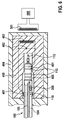
- das steckerseitige Ende des in
Fig. 1 dargestellten Ausführungsbeispiels einer Elektrodenleitung, teilweise geschnitten, und - Fig. 6
- einen erfindungsgemäßen Ausleseadapter mit eingesteckter Elektrodenleitung gemäß
Fig. 1 und eine sterile Verpackung in einem Querschnitt. - Die in
Fig. 1, 2 und5 gezeigte erfindungsgemäße Elektrodenleitung 100 mit einem außen liegenden Isolationsmantel 102 ist als Mehrlumenschlauch aus einem geeigneten extrudierbaren Polymer ausgebildet. Die Elektrodenleitung 100 weist einen Außenleiter 104 (z. B. eine drahtgewickelte Wendel oder Drahtseil), einen mit einem Kontakt an der Elektrodenspitze (z.B. die Tip-Elektrode einer Schrittmacher-Elektrode) verbundenen Innenleiter 105 sowie eine dazwischen angeordnete Isolationsschicht 106 auf. Der Außenleiter 104 ist mit einem anderen Kontakt an der Elektrodenspitze (z.B. RingElektrode einer Schrittmacherelektrode) verbunden.
Die Elektrodenleitung 100 weist ferner einen Stecker 111 auf, um die Elektrodenleitung 100 zum Beispiel mit dem Implantat 300 zu verbinden. Zur Herstellung eines Kontakts zwischen Elektrodenleitung 100 und Implantat 300 verfügt der Stecker 111 über einen Spitzenkontakt 113 und einen oder mehrere Ringkontakte 112. Der Spitzenkontakt 113 des Steckers 111 kann beispielsweise mit dem Innenleiter 105 und der Außenleiter 104 kann mit einem der Ringkontakte 112 des Steckers 111 verbunden sein. - Die elektrischen Leiter der Elektrodenleitung können jedoch auch als Nicht-Koaxialkabel ausgebildet sein und nebeneinander in dem Isolationsmantel 102 vorliegen. Alternativ kann lediglich ein einziger Leiter in der Elektrodenleitung 100 angeordnet sein (z.B. für eine unipolare Elektrode oder Schock-Elektrode).
- Die Elektrodenleitung weist ferner, eingebettet in den Isolationsmantel 102 einen ID-Schaltkreis 200 auf. Ein erster Anschluss der Anschlüsse 208 des ID-Schaltkreises 200 ist elektrisch leitend mit dem Außenleiter 104 und ein zweiter Anschluss der Anschlüsse 208 des ID-Schaltkreises 200 mit einem außen auf dem Isolationsmantel 102 angeordneten elektrisch leitenden Ring 110 verbunden. Die Verbindung mit dem Außenleiter 104 ist vorteilhaft, da sie kostengünstig realisiert werden kann. Würde stattdessen eine Verbindung des ID-Schaltkreises 200 mit dem Innenleiter 105 erfolgen, was prinzipiell auch möglich ist, müsste die Anschlussleitung isoliert durch den Außenleiter 104 hindurch geführt werden. Durch den elektrisch leitenden Ring 110 erfolgt der Rückkontakt des ID-Schaltkreises 200 über das Körpergewebe zu dem Gehäuse eines Implantats 300, mit dem, wie unten dargestellt, mindestens eine individuelle Eigenschaft der Elektrodenleitung 100 ausgelesen werden kann. Der elektrisch leitende Ring 110 ist deshalb in einem vorgegebenen Abstand von dem Stecker, der zum Einführen in eine Buchse des Implantats 300 ausgebildet ist, um die Elektrodenleitung 100 mit dem Implantat 300 zu verbinden, angeordnet. Bei nebeneinander in dem Isolationsmantel 102 liegenden elektrischen Leitern kann der leiterseitige Anschluss 208 des ID-Schaltkreises 200 mit einem der elektrischen Leiter verbunden sein.
- Das Auslesen des ID-Schaltkreises 200 erfolgt mittels Wechselspannung. Daher ist am Anschluss 208 des ID-Schaltkreises 200 ein Gleichrichter 202 vorgesehen. Die Ausgänge dieses Gleichrichters sind sowohl mit Eingängen zur Spannungsversorgung (VCC, GND) eines ID-Chips 201 als auch mit dessen Signaleingängen A und B verbunden. Die Verbindung erfolgt über einen Schutzwiderstand 203, der beispielsweise einen Widerstand von 50 kΩ besitzt. Parallel zu den Eingängen zur Spannungsversorgung ist ein Spannungsbegrenzer 204, beispielsweise eine Z-Diode oder ein Varistor vorgesehen. Der Effektivwert der Wechselspannung beträgt beispielsweise 3 V mit einer Frequenz von 100 kHz. Der Gleichrichter hat eine Spannungsfestigkeit, welche der im bestimmungsgemäßen Therapiebetrieb maximal auftretenden Spannung entspricht, beispielsweise 1 kV. Über die Anschlüsse 208 für die Energieversorgung erfolgt gleichzeitig die Kommunikation mit den Signaleingängen A, B des ID-Chips 201, vorzugsweise mittels Lastmodulation durch einen Schalttransistor 205. Um die Energieversorgung des ID-Chips 201 während der Lastmodulation zu sichern, sind die Anschlüsse 208 für die Energieversorgung mit einer Schaltdiode 206 und einem Pufferkondensator 207 beschaltet. Der Pufferkondensator hat beispielsweise eine Kapazität von 1 nF.
- Der ID-Chip 201 besitzt eine Eindraht-Schnittstelle zur Kommunikation mit einer ID-Kommunikationseinheit 303 des Implantats 300 zum Auslesen mindestens einer individuellen Eigenschaft (z.B. Seriennummer, Typbezeichnung etc. siehe oben) der Elektrodenleitung 100, welche in einer Speichereinheit des ID-Chips 201 gespeichert ist. Vorzugsweise weist die Speichereinheit des ID-Chips auch einen beschreibbaren Speicherbereich zum Einschreiben von Daten auf, welche über die Eindraht-Schnittstelle des ID-Chips 201 übermittelt werden können.
- Zur Abfrage einer Elektrodenleitung gemäß
Figur 1 und 2 kann beispielsweise das inFigur 4 dargestellte Implantat 300 verwendet werden. Das Implantat besitzt eine Steuerungseinheit 301, welche mit einem geeigneten Multiplexer 302 und einer ID-Kommunikationseinheit 303 verbunden ist. Ferner sind eine Therapie- und Diagnostikeinheit 304 sowie eine Telemetrieeinheit 305 vorgesehen, wobei die Telemetrieeinheit 305 mit einer Antenne 307 verbunden ist. Sowohl die Telemetrieeinheit 305 als auch die Therapie- und Diagnostikeinheit 304 sind ebenfalls mit der Steuerungseinheit 301 verbunden. Für ein Auslesen einer mit dem Implantat 300 verbundenen Elektrodenleitung 100, beispielsweise durch Einstecken des Steckers der Elektrodenleitung 100 in eine Buchse des Implantats 300, werden die entsprechenden Elektrodenanschlüsse 306 des Implantats durch den Multiplexer 302 mit der ID-Kommunikationseinheit 303 verbunden. Im Therapie- oder Diagnosebetrieb des Implantats 300 verbindet der Multiplexer 302 die Elektrodenanschlüsse 306 stattdessen mit der Therapie- und Diagnostikeinheit 304 des Implantats 300. - Für die Kommunikation mit der Eindraht-Schnittstelle des ID-Chips 201 des ID-Schaltkreises werden ein erster vorgegebener Anschluss des Implantats 100 mittels des Multiplexers 302 mit der Außenleitung 104 der Elektrodenleitung 100 und ein zweiter vorgegebener Anschluss mit dem Gehäuse des Implantats 300 verbunden. Ferner wird die ID-Kommunikationseinheit 303 aktiviert. Nun veranlasst die Steuerungseinheit 301 ein Anlegen einer effektiven Wechselspannung von beispielsweise 3 V mit einer Frequenz von 100 kHz zwischen dem vorgegebenen ersten und zweiten Anschluss, welche somit auch an den Anschlüssen 208 des ID-Schaltkreises 200 anliegt. Nun erfolgt durch die ID-Kommunikationseinheit 303 ein Auslesen mindestens einer individuellen Eigenschaft aus der Speichereinheit des ID-Chips 201 über die Eindraht-Schnittstelle und/oder ein Einschreiben von Daten in den beschreibbaren Speicherbereich des ID-Chips 201 über diese Schnittstelle. Die ausgelesenen Daten können in einer Speichereinheit der Steuerungseinheit 301 abgespeichert oder über die Telemetrieeinheit 305 an ein weiteres Gerät, beispielsweise ein externes Patientengerät, übertragen werden. Das Patientengerät kann diese Information an eine Telemonitoring-Plattform übertragen. Ebenso ist es möglich, auf diesem Wege Informationen in einem beschreibbaren Speicherbereich der Speichereinheit des ID-Chips 201 abzuspeichern, die aus der Steuerungseinheit 301 des Implantats 300 selbst, aus einem anderen Gerät (zum Beispiel Patientengerät) oder aus einer Telemonitoring-Plattform stammen.
- Anhand der aus der Elektrodenleitung 100 ausgelesenen Informationen kann das Implantat 300 automatisch die Anschlussbelegung der Elektrodenleitung feststellen und konfigurieren und/oder Therapieparameter an die erkannte Elektrodenleitung anpassen. Die aus der Elektrodenleitung ausgelesenen Informationen, beispielsweise eine Seriennummer, können für die Dokumentation, die Rückverfolgbarkeit des Produktes (Chargenrückverfolgung), Fehleranalyse oder deren Auswahl für bestimmte Anwendungen verwendet werden.
- Um die Informationen aus der Elektrodenleitung auch im nicht implantierten, z.B. verpackten Zustand auslesen zu können, kann während Herstellung, Lagerung und Versand ein in
Fig. 6 dargestellter Ausleseadapter 400, der eine Spule 403 aus elektrisch leitendem Material aufweist, derart auf den Stecker 111 der Elektrodenleitung 100 gesteckt werden, dass dessen einer Anschluss (Kontaktklemme 401) mit dem elektrisch leitenden Ring 110 und dessen anderer Anschluss (Kontaktklemme 401) mit einem elektrischen Leiter der Elektrodenleitung 100, zum Beispiel mit dem Außenleiter 104 über einen Ringkontakt 112 des Steckers 111, verbunden ist. Der Ausleseadapter 400 besteht vorzugsweise aus einem elektrisch nicht leitenden, nichtmetallischen Material, beispielsweise Kunststoff, Epoxidharz, Silikon, oder dergleichen. Der Ausleseadapter 400 kann z.B. zylinderförmig oder quaderförmig gestaltet sein, wobei beliebige andere Formen ebenfalls denkbar sind. Der Ausleseadapter enthält eine z.B. zylinderförmige Ausnehmung (Buchse) 405, die zum Einstecken des Steckers 111 der Elektrodenleitung dient. Aus der Innenwand der Ausnehmung 405 ragen die Kontaktklemmen 401 heraus und in die Ausnehmung 405 hinein. Die Spule 403 ist durch geeignete Beschaltung mit einem Kondensator 402 zu einem Resonanzkreis erweitert, dessen Resonanzfrequenz vorzugsweise der Arbeitsfrequenz einer vom Implantat verschiedenen Ausleseeinrichtung 500 entspricht. Vor Verwendung des Elektrodenleiters 100 ist die Kombination aus eingestecktem Elektrodenleiter 100 und Ausleseadapter 400 in einer verschlossenen sterilen Verpackung 404 angeordnet. Die sterile Verpackung 404 besteht ebenfalls vorzugsweise aus einem elektrisch nicht leitenden, nichtmetallischen Material. - In dem Zustand, in dem der Ausleseadapter auf die zu vermessende Elektrodenleitung aufgesteckt ist, ähnelt diese Anordnung in ihrer Arbeitsweise einem RFID-Transponder bekannter Art, beispielsweise einem RFID-Transponder für das 125 kHz Band. Als Ausleseeinrichtung für das Auslesen und Beschreiben der Speichereinheit des ID-Chips 201 in dieser Anordnung kann eine bekannte Ausleseeinrichtung 500 für einen solchen RFID-Transponder mit einer Abfragespule 501 verwendet werden. Mit dieser Anordnung ist es möglich, die Elektrodenleitung 100 kontaktlos mittels induktiver Kopplung auch durch eine sterile Verpackung hindurch auszulesen oder einzuschreiben. Das Auslesegerät kann ein Display enthalten, auf dem die ausgelesenen Informationen dargestellt werden können und/oder eine Eingabemöglichkeit enthalten, über die die einzuspeichernden Informationen eingegeben werden können. Fernerhin kann das Auslesegerät 500 mit einer Datenverbindung geeigneter Art an ein Datennetzwerk angeschlossen sein, in das die ausgelesenen Informationen übertragen werden oder aus dem die einzuspeichernden Informationen bezogen werden können.
-
- 100
- Elektrodenleitung
- 102
- Isolationsmantel
- 104
- Außenleiter
- 105
- Innenleiter
- 106
- Isolationsschicht
- 110
- elektrisch leitender Ring
- 111
- Stecker
- 112
- Ringkontakt des Steckers 111
- 113
- Spitzenkontakt des Steckers 111
- 200
- ID-Schaltkreis
- 201
- ID-Chip
- 202
- Gleichrichter
- 203
- Schutzwiderstand
- 204
- Spannungsbegrenzer
- 205
- Schalttransistor
- 206
- Diode
- 207
- Pufferkondensator
- 208
- Anschluss des ID-Schaltkreises 200 zur Spannungsversorgung
- 300
- Implantat
- 301
- Steuerungseinheit
- 302
- Anschluss-Multiplexer
- 303
- ID-Kommunikationseinheit
- 304
- Therapie- oder Diagnostikeinheit
- 305
- Telemetrieeinheit
- 306
- Anschlüsse des Implantats
- 307
- Antenne
- 400
- Ausleseadapter
- 401
- Kontaktklemme
- 402
- Kondensator des Ausleseadapters 400
- 403
- Spule des Ausleseadapters 400
- 404
- sterile Verpackung
- 405
- Ausnehmung in dem Ausleseadapter 400
- 500
- RFID-Ausleseeinrichtung
- 501
- Abfragespule der RFID-Ausleseeinrichtung 500
Claims (12)
- Elektrodenleitung (100) zur Verbindung mit einem Implantat (300) mittels eines Steckers mit mindestens einem elektrischen Leiter (104, 105) und einem Isolationsmantel (102),
gekennzeichnet durch einen in dem Isolationsmantel (102) angeordneten ID-Schaltkreis (200) mit einem ID-Chip (201), wobei der ID-Schaltkreis (200) mit seinem ersten Anschluss mit einem elektrischen Leiter (104) und mit seinem zweiten Anschluss mit einem außen auf der Elektrodenleitung frei liegenden elektrisch leitenden Element (110) verbunden ist, wobei der ID-Chip (201) eine Speichereinheit aufweist und das elektrisch leitende Element (110) in Längsrichtung der Elektrodenleitung (100) in einem vorgegebenen Abstand von dem Stecker angeordnet ist, wobei in der Speichereinheit mindestens eine individuelle Eigenschaft der Elektrodenleitung (100), beispielsweise die zugehörige ID-Nummer, Losnummer, Typ, die Ausführung, Revision oder dergl., gespeichert ist. - Elektrodenleitung (100) nach Anspruch 1, dadurch gekennzeichnet, dass der ID-Chip (201) eine Eindraht-Schnittstelle aufweist.
- Elektrodenleitung (100) nach einem der vorhergehenden Ansprüche, dadurch gekennzeichnet, dass das elektrisch leitende Element als elektrisch leitender Ring, Draht, Seil, Litze oder Folie (110) ausgebildet ist.
- Elektrodenleitung (100) nach einem der vorhergehenden Ansprüche, dadurch gekennzeichnet, dass die Speichereinheit einen beschreibbaren Speicherbereich aufweist.
- Elektrodenleitung (100) nach einem der vorhergehenden Ansprüche, dadurch gekennzeichnet, dass der ID-Schaltkreis (200) einen Schalttransistor (205) aufweist, der parallel zu dem ID-Chip (201) geschaltet ist und zur Kommunikation mit dem Implantat (300) mittels Lastmodulation dient.
- Elektrodenleitung (100) nach einem der vorhergehenden Ansprüche, dadurch gekennzeichnet, dass der ID-Schaltkreis (200) einen Spannungsbegrenzer (204) aufweist.
- Elektrodenleitung (100) nach einem der vorhergehenden Ansprüche, dadurch gekennzeichnet, dass der ID-Schaltkreis eine Beschaltung aus Diode (206) und Pufferkondensator (207) zur Energieversorgung während der Lastmodulation aufweist.
- Verfahren zur Identifikation einer Elektrodenleitung (100) nach einem der Ansprüche 1 bis 7 mittels eines Implantats (300), umfassend die folgenden Schritte:- Verbinden des ersten Anschlusses des ID-Schaltkreises (200) und des zweiten Anschlusses des ID-Schaltkreises (200) mit einer ID-Kommunikationseinheit (303) des Implantats (300), wobei der erste Anschluss des ID-Schaltkreises mit einem vorgegebenen elektrischen Leiter (104) der Elektrodenleitung (100) und der zweite Anschluss des ID-Schaltkreises mit einem Gehäuse des Implantats (300) verbunden wird,- Anlegen einer Wechselspannung zwischen dem ersten Anschluss und dem zweiten Anschluss (208) des ID-Schaltkreises (200),- Auslesen mindestens einer gewünschten individuellen Eigenschaft aus der Speichereinheit des ID-Chips (201) über die Eindraht-Schnittstelle mittels der ID-Kommunikationseinheit (303),- Speichern der mindestens einen ausgelesenen individuellen Eigenschaft in einer Speichereinheit des Implantats (300).
- Verfahren nach Anspruch 8, dadurch gekennzeichnet, dass durch die ID-Kommunikationseinheit (303) über die Eindraht-Schnittstelle zusätzlich vorgegebene Daten in einen beschreibbaren Speicherbereich der Speichereinheit des ID-Schaltkreises (200) eingeschrieben werden.
- Verfahren zur Konfiguration eines Systems bestehend aus einem Implantat (300) und mindestens einer Elektrodenleitung (100) nach einem der Ansprüche 1 bis 7, umfassend die folgenden Schritte:- Identifikation der mindestens einen, mit dem Implantat (300) verbundenen Elektrodenleitung (100) mittels eines Verfahrens nach einem der Ansprüche 8 bis 9,- Konfiguration der Ansteuerung der mit der ausgelesenen Elektrodenleitung (100) verbundenen Anschlüsse (306) des Implantats (300) und/oder der Therapieparameter.
- Implantat (300) mit einer Buchse zur Verbindung mit dem Stecker einer Elektrodenleitung (100) nach einem der Ansprüche 1 bis 7 und mit einem Gehäuse, mit einer ID-Kommunikationseinheit (303), welche mit einem vorgegebenen elektrischen Leiter (104, 105) der Elektrodenleitung (100) und dem Gehäuse des Implantats (300) verbindbar und zur Erzeugung einer Wechselspannung zwischen Gehäuse und dem vorgegebenen elektrischen Leiter (104) eingerichtet ist, wobei die ID-Kommunikationseinheit weiter zum Auslesen mindestens einer gewünschten individuellen Eigenschaft der Speichereinheit des ID-Chips (201), vorzugsweise über dessen Eindraht-Schnittstelle, und Speichern der mindestens einen ausgelesenen individuellen Eigenschaft in einer Speichereinheit des Implantats (300) eingerichtet ist.
- Ausleseadapter (400) mit einer Spule (403), welche an ihrem ersten Ende mit einem vorgegebenen elektrischen Leiter (104, 105) der Elektrodenleitung (100) nach einem der Ansprüche 1 bis 7 und mit ihrem zweiten Ende mit dem elektrisch leitenden Element (110) der Elektrodenleitung (100) verbindbar ist.
Priority Applications (5)
| Application Number | Priority Date | Filing Date | Title |
|---|---|---|---|
| EP16184298.4A EP3284511B1 (de) | 2016-08-16 | 2016-08-16 | Elektrodenleitung, implantat und verfahren zur identifikation einer elektrodenleitung |
| US15/667,680 US10500400B2 (en) | 2016-08-16 | 2017-08-03 | Electrode lead, implant, and method for identifying an electrode lead |
| EP17184616.5A EP3284516B1 (de) | 2016-08-16 | 2017-08-03 | Implantat und verfahren zur identifikation einer elektrodenleitung |
| US15/667,684 US10874863B2 (en) | 2016-08-16 | 2017-08-03 | Electrode lead, implant, and method for identifying an electrode lead |
| EP17184617.3A EP3284517B1 (de) | 2016-08-16 | 2017-08-03 | Implantat und verfahren zur identifikation einer elektrodenleitung |
Applications Claiming Priority (1)
| Application Number | Priority Date | Filing Date | Title |
|---|---|---|---|
| EP16184298.4A EP3284511B1 (de) | 2016-08-16 | 2016-08-16 | Elektrodenleitung, implantat und verfahren zur identifikation einer elektrodenleitung |
Publications (2)
| Publication Number | Publication Date |
|---|---|
| EP3284511A1 true EP3284511A1 (de) | 2018-02-21 |
| EP3284511B1 EP3284511B1 (de) | 2021-06-09 |
Family
ID=56686735
Family Applications (1)
| Application Number | Title | Priority Date | Filing Date |
|---|---|---|---|
| EP16184298.4A Active EP3284511B1 (de) | 2016-08-16 | 2016-08-16 | Elektrodenleitung, implantat und verfahren zur identifikation einer elektrodenleitung |
Country Status (1)
| Country | Link |
|---|---|
| EP (1) | EP3284511B1 (de) |
Citations (9)
| Publication number | Priority date | Publication date | Assignee | Title |
|---|---|---|---|---|
| US5720293A (en) * | 1991-01-29 | 1998-02-24 | Baxter International Inc. | Diagnostic catheter with memory |
| US20030018369A1 (en) | 2001-07-17 | 2003-01-23 | Medtronic, Inc. | Method and apparatus for automatic implantable medical lead recognition and configuration |
| US20040073265A1 (en) | 2002-10-10 | 2004-04-15 | Avram Scheiner | Connection verification apparatus, systems, and methods |
| US20070203547A1 (en) * | 2005-12-15 | 2007-08-30 | Costello Benedict J | Medical device identification |
| DE102008040867A1 (de) * | 2008-06-09 | 2009-12-10 | Biotronik Crm Patent Ag | System und Anordnung zur Identifizierung von implantierbaren Elektroden |
| US7713194B2 (en) | 2004-09-02 | 2010-05-11 | Proteus Biomedical, Inc. | Methods for configuring satellite electrodes |
| US20110112609A1 (en) | 2009-11-09 | 2011-05-12 | Boston Scientific Neuromodulation Corporation | Automatic lead identification using electric field fingerprinting |
| US20120123496A1 (en) | 2010-11-12 | 2012-05-17 | Medtronic, Inc. | Connectivity detection and type identification of an implanted lead for an implantable medical device |
| US20140343633A1 (en) | 2011-06-30 | 2014-11-20 | Greatbatch Ltd. | Electrically identifiable electrode lead and method of electrically identifying an electrode lead |
-
2016
- 2016-08-16 EP EP16184298.4A patent/EP3284511B1/de active Active
Patent Citations (10)
| Publication number | Priority date | Publication date | Assignee | Title |
|---|---|---|---|---|
| US5720293A (en) * | 1991-01-29 | 1998-02-24 | Baxter International Inc. | Diagnostic catheter with memory |
| US20030018369A1 (en) | 2001-07-17 | 2003-01-23 | Medtronic, Inc. | Method and apparatus for automatic implantable medical lead recognition and configuration |
| US20040073265A1 (en) | 2002-10-10 | 2004-04-15 | Avram Scheiner | Connection verification apparatus, systems, and methods |
| US20060212083A1 (en) | 2002-10-10 | 2006-09-21 | Cardiac Pacemakers, Inc. | Connection verification apparatus, systems, and methods |
| US7713194B2 (en) | 2004-09-02 | 2010-05-11 | Proteus Biomedical, Inc. | Methods for configuring satellite electrodes |
| US20070203547A1 (en) * | 2005-12-15 | 2007-08-30 | Costello Benedict J | Medical device identification |
| DE102008040867A1 (de) * | 2008-06-09 | 2009-12-10 | Biotronik Crm Patent Ag | System und Anordnung zur Identifizierung von implantierbaren Elektroden |
| US20110112609A1 (en) | 2009-11-09 | 2011-05-12 | Boston Scientific Neuromodulation Corporation | Automatic lead identification using electric field fingerprinting |
| US20120123496A1 (en) | 2010-11-12 | 2012-05-17 | Medtronic, Inc. | Connectivity detection and type identification of an implanted lead for an implantable medical device |
| US20140343633A1 (en) | 2011-06-30 | 2014-11-20 | Greatbatch Ltd. | Electrically identifiable electrode lead and method of electrically identifying an electrode lead |
Also Published As
| Publication number | Publication date |
|---|---|
| EP3284511B1 (de) | 2021-06-09 |
Similar Documents
| Publication | Publication Date | Title |
|---|---|---|
| EP3284516B1 (de) | Implantat und verfahren zur identifikation einer elektrodenleitung | |
| DE60223146T2 (de) | Automatische erkennung und konfiguration implantierbarer medizinischer leitungen | |
| DE602004005484T2 (de) | Implantierbares satellitenmodul und system zur interaktion mit einem angezielten gewebe eines patienten | |
| EP1062969B1 (de) | Elektrodenanordnung | |
| DE69725327T2 (de) | Eine stimulationsvorrichtung | |
| DE69832713T2 (de) | Batterie-betriebsgerät zur implantation in einem patienten | |
| US9234920B2 (en) | Electrically identifiable electrode lead and method of electrically identifying an electrode lead | |
| EP3278836A1 (de) | Elektromedizinisches implantat mit einer elektrischen durchführung | |
| DE3490016T1 (de) | Implantierbare Hyperthermie-Einrichtung und -System | |
| DE2803366A1 (de) | Programmierbares stimulationssystem fuer menschliches gewebe | |
| EP2016892A1 (de) | Implantierbares medizinisches Gerät | |
| DE112008003193T5 (de) | Anordnung verbundener Mikrotransponder für Implantation | |
| EP2502646B1 (de) | Implantierbares Gerät | |
| DE3914677C2 (de) | ||
| EP2578268B1 (de) | Temperatursensor für ein implantierbares medizinisches Gerät | |
| EP3284511B1 (de) | Elektrodenleitung, implantat und verfahren zur identifikation einer elektrodenleitung | |
| EP3284510B1 (de) | Elektrodenleitung, implantat und verfahren zur identifikation einer elektrodenleitung | |
| EP3284508B1 (de) | Implantat und verfahren zur identifikation einer elektrodenleitung | |
| DE102008040867A1 (de) | System und Anordnung zur Identifizierung von implantierbaren Elektroden | |
| EP2191862B1 (de) | Adapter, Adapter-Verkaufseinheit und System aus dem Adapter, einem implantierbaren medizinelektronischen Gerät und einer Elektrodenleitung | |
| EP2465569A2 (de) | Implantierbares Gerät | |
| EP2478932A2 (de) | Implantierbares Gerät | |
| EP3704440B1 (de) | Justierhilfe, drahtlose verbinderanordnung und verfahren zum überwachen einer position | |
| DE3722829C2 (de) | Verfahren und Anordnung zur Steuerung der Impulsabgabe eines implantierbaren elektromedizinischen Gerätes | |
| EP2985054B1 (de) | Implantierbares gerät mit elektrischem filter |
Legal Events
| Date | Code | Title | Description |
|---|---|---|---|
| PUAI | Public reference made under article 153(3) epc to a published international application that has entered the european phase |
Free format text: ORIGINAL CODE: 0009012 |
|
| STAA | Information on the status of an ep patent application or granted ep patent |
Free format text: STATUS: THE APPLICATION HAS BEEN PUBLISHED |
|
| AK | Designated contracting states |
Kind code of ref document: A1 Designated state(s): AL AT BE BG CH CY CZ DE DK EE ES FI FR GB GR HR HU IE IS IT LI LT LU LV MC MK MT NL NO PL PT RO RS SE SI SK SM TR |
|
| AX | Request for extension of the european patent |
Extension state: BA ME |
|
| STAA | Information on the status of an ep patent application or granted ep patent |
Free format text: STATUS: REQUEST FOR EXAMINATION WAS MADE |
|
| 17P | Request for examination filed |
Effective date: 20180723 |
|
| RBV | Designated contracting states (corrected) |
Designated state(s): AL AT BE BG CH CY CZ DE DK EE ES FI FR GB GR HR HU IE IS IT LI LT LU LV MC MK MT NL NO PL PT RO RS SE SI SK SM TR |
|
| RIC1 | Information provided on ipc code assigned before grant |
Ipc: A61N 1/375 20060101AFI20201130BHEP Ipc: A61B 5/00 20060101ALN20201130BHEP Ipc: A61N 1/02 20060101ALI20201130BHEP Ipc: A61B 5/042 20060101ALI20201130BHEP Ipc: A61N 1/05 20060101ALI20201130BHEP |
|
| GRAP | Despatch of communication of intention to grant a patent |
Free format text: ORIGINAL CODE: EPIDOSNIGR1 |
|
| STAA | Information on the status of an ep patent application or granted ep patent |
Free format text: STATUS: GRANT OF PATENT IS INTENDED |
|
| RIC1 | Information provided on ipc code assigned before grant |
Ipc: A61N 1/375 20060101AFI20201209BHEP Ipc: A61B 5/00 20060101ALN20201209BHEP Ipc: A61N 1/02 20060101ALI20201209BHEP Ipc: A61N 1/05 20060101ALI20201209BHEP Ipc: A61B 5/042 20060101ALI20201209BHEP |
|
| INTG | Intention to grant announced |
Effective date: 20210112 |
|
| GRAS | Grant fee paid |
Free format text: ORIGINAL CODE: EPIDOSNIGR3 |
|
| GRAA | (expected) grant |
Free format text: ORIGINAL CODE: 0009210 |
|
| STAA | Information on the status of an ep patent application or granted ep patent |
Free format text: STATUS: THE PATENT HAS BEEN GRANTED |
|
| AK | Designated contracting states |
Kind code of ref document: B1 Designated state(s): AL AT BE BG CH CY CZ DE DK EE ES FI FR GB GR HR HU IE IS IT LI LT LU LV MC MK MT NL NO PL PT RO RS SE SI SK SM TR |
|
| REG | Reference to a national code |
Ref country code: GB Ref legal event code: FG4D Free format text: NOT ENGLISH |
|
| REG | Reference to a national code |
Ref country code: CH Ref legal event code: EP Ref country code: AT Ref legal event code: REF Ref document number: 1399962 Country of ref document: AT Kind code of ref document: T Effective date: 20210615 |
|
| REG | Reference to a national code |
Ref country code: DE Ref legal event code: R096 Ref document number: 502016013172 Country of ref document: DE |
|
| REG | Reference to a national code |
Ref country code: IE Ref legal event code: FG4D Free format text: LANGUAGE OF EP DOCUMENT: GERMAN |
|
| REG | Reference to a national code |
Ref country code: LT Ref legal event code: MG9D |
|
| PG25 | Lapsed in a contracting state [announced via postgrant information from national office to epo] |
Ref country code: FI Free format text: LAPSE BECAUSE OF FAILURE TO SUBMIT A TRANSLATION OF THE DESCRIPTION OR TO PAY THE FEE WITHIN THE PRESCRIBED TIME-LIMIT Effective date: 20210609 Ref country code: LT Free format text: LAPSE BECAUSE OF FAILURE TO SUBMIT A TRANSLATION OF THE DESCRIPTION OR TO PAY THE FEE WITHIN THE PRESCRIBED TIME-LIMIT Effective date: 20210609 Ref country code: HR Free format text: LAPSE BECAUSE OF FAILURE TO SUBMIT A TRANSLATION OF THE DESCRIPTION OR TO PAY THE FEE WITHIN THE PRESCRIBED TIME-LIMIT Effective date: 20210609 Ref country code: BG Free format text: LAPSE BECAUSE OF FAILURE TO SUBMIT A TRANSLATION OF THE DESCRIPTION OR TO PAY THE FEE WITHIN THE PRESCRIBED TIME-LIMIT Effective date: 20210909 |
|
| REG | Reference to a national code |
Ref country code: NL Ref legal event code: MP Effective date: 20210609 |
|
| PG25 | Lapsed in a contracting state [announced via postgrant information from national office to epo] |
Ref country code: NO Free format text: LAPSE BECAUSE OF FAILURE TO SUBMIT A TRANSLATION OF THE DESCRIPTION OR TO PAY THE FEE WITHIN THE PRESCRIBED TIME-LIMIT Effective date: 20210909 Ref country code: SE Free format text: LAPSE BECAUSE OF FAILURE TO SUBMIT A TRANSLATION OF THE DESCRIPTION OR TO PAY THE FEE WITHIN THE PRESCRIBED TIME-LIMIT Effective date: 20210609 Ref country code: RS Free format text: LAPSE BECAUSE OF FAILURE TO SUBMIT A TRANSLATION OF THE DESCRIPTION OR TO PAY THE FEE WITHIN THE PRESCRIBED TIME-LIMIT Effective date: 20210609 Ref country code: LV Free format text: LAPSE BECAUSE OF FAILURE TO SUBMIT A TRANSLATION OF THE DESCRIPTION OR TO PAY THE FEE WITHIN THE PRESCRIBED TIME-LIMIT Effective date: 20210609 Ref country code: GR Free format text: LAPSE BECAUSE OF FAILURE TO SUBMIT A TRANSLATION OF THE DESCRIPTION OR TO PAY THE FEE WITHIN THE PRESCRIBED TIME-LIMIT Effective date: 20210910 |
|
| PG25 | Lapsed in a contracting state [announced via postgrant information from national office to epo] |
Ref country code: EE Free format text: LAPSE BECAUSE OF FAILURE TO SUBMIT A TRANSLATION OF THE DESCRIPTION OR TO PAY THE FEE WITHIN THE PRESCRIBED TIME-LIMIT Effective date: 20210609 Ref country code: CZ Free format text: LAPSE BECAUSE OF FAILURE TO SUBMIT A TRANSLATION OF THE DESCRIPTION OR TO PAY THE FEE WITHIN THE PRESCRIBED TIME-LIMIT Effective date: 20210609 Ref country code: SM Free format text: LAPSE BECAUSE OF FAILURE TO SUBMIT A TRANSLATION OF THE DESCRIPTION OR TO PAY THE FEE WITHIN THE PRESCRIBED TIME-LIMIT Effective date: 20210609 Ref country code: SK Free format text: LAPSE BECAUSE OF FAILURE TO SUBMIT A TRANSLATION OF THE DESCRIPTION OR TO PAY THE FEE WITHIN THE PRESCRIBED TIME-LIMIT Effective date: 20210609 Ref country code: PT Free format text: LAPSE BECAUSE OF FAILURE TO SUBMIT A TRANSLATION OF THE DESCRIPTION OR TO PAY THE FEE WITHIN THE PRESCRIBED TIME-LIMIT Effective date: 20211011 Ref country code: NL Free format text: LAPSE BECAUSE OF FAILURE TO SUBMIT A TRANSLATION OF THE DESCRIPTION OR TO PAY THE FEE WITHIN THE PRESCRIBED TIME-LIMIT Effective date: 20210609 Ref country code: RO Free format text: LAPSE BECAUSE OF FAILURE TO SUBMIT A TRANSLATION OF THE DESCRIPTION OR TO PAY THE FEE WITHIN THE PRESCRIBED TIME-LIMIT Effective date: 20210609 Ref country code: ES Free format text: LAPSE BECAUSE OF FAILURE TO SUBMIT A TRANSLATION OF THE DESCRIPTION OR TO PAY THE FEE WITHIN THE PRESCRIBED TIME-LIMIT Effective date: 20210609 |
|
| PG25 | Lapsed in a contracting state [announced via postgrant information from national office to epo] |
Ref country code: PL Free format text: LAPSE BECAUSE OF FAILURE TO SUBMIT A TRANSLATION OF THE DESCRIPTION OR TO PAY THE FEE WITHIN THE PRESCRIBED TIME-LIMIT Effective date: 20210609 |
|
| REG | Reference to a national code |
Ref country code: DE Ref legal event code: R097 Ref document number: 502016013172 Country of ref document: DE |
|
| REG | Reference to a national code |
Ref country code: CH Ref legal event code: PL |
|
| PG25 | Lapsed in a contracting state [announced via postgrant information from national office to epo] |
Ref country code: MC Free format text: LAPSE BECAUSE OF FAILURE TO SUBMIT A TRANSLATION OF THE DESCRIPTION OR TO PAY THE FEE WITHIN THE PRESCRIBED TIME-LIMIT Effective date: 20210609 |
|
| PLBE | No opposition filed within time limit |
Free format text: ORIGINAL CODE: 0009261 |
|
| STAA | Information on the status of an ep patent application or granted ep patent |
Free format text: STATUS: NO OPPOSITION FILED WITHIN TIME LIMIT |
|
| REG | Reference to a national code |
Ref country code: BE Ref legal event code: MM Effective date: 20210831 |
|
| PG25 | Lapsed in a contracting state [announced via postgrant information from national office to epo] |
Ref country code: LI Free format text: LAPSE BECAUSE OF NON-PAYMENT OF DUE FEES Effective date: 20210831 Ref country code: DK Free format text: LAPSE BECAUSE OF FAILURE TO SUBMIT A TRANSLATION OF THE DESCRIPTION OR TO PAY THE FEE WITHIN THE PRESCRIBED TIME-LIMIT Effective date: 20210609 Ref country code: CH Free format text: LAPSE BECAUSE OF NON-PAYMENT OF DUE FEES Effective date: 20210831 |
|
| 26N | No opposition filed |
Effective date: 20220310 |
|
| GBPC | Gb: european patent ceased through non-payment of renewal fee |
Effective date: 20210909 |
|
| PG25 | Lapsed in a contracting state [announced via postgrant information from national office to epo] |
Ref country code: LU Free format text: LAPSE BECAUSE OF NON-PAYMENT OF DUE FEES Effective date: 20210816 Ref country code: AL Free format text: LAPSE BECAUSE OF FAILURE TO SUBMIT A TRANSLATION OF THE DESCRIPTION OR TO PAY THE FEE WITHIN THE PRESCRIBED TIME-LIMIT Effective date: 20210609 |
|
| PG25 | Lapsed in a contracting state [announced via postgrant information from national office to epo] |
Ref country code: IT Free format text: LAPSE BECAUSE OF FAILURE TO SUBMIT A TRANSLATION OF THE DESCRIPTION OR TO PAY THE FEE WITHIN THE PRESCRIBED TIME-LIMIT Effective date: 20210609 Ref country code: IE Free format text: LAPSE BECAUSE OF NON-PAYMENT OF DUE FEES Effective date: 20210816 Ref country code: GB Free format text: LAPSE BECAUSE OF NON-PAYMENT OF DUE FEES Effective date: 20210909 Ref country code: FR Free format text: LAPSE BECAUSE OF NON-PAYMENT OF DUE FEES Effective date: 20210831 Ref country code: BE Free format text: LAPSE BECAUSE OF NON-PAYMENT OF DUE FEES Effective date: 20210831 |
|
| REG | Reference to a national code |
Ref country code: AT Ref legal event code: MM01 Ref document number: 1399962 Country of ref document: AT Kind code of ref document: T Effective date: 20210816 |
|
| PG25 | Lapsed in a contracting state [announced via postgrant information from national office to epo] |
Ref country code: AT Free format text: LAPSE BECAUSE OF NON-PAYMENT OF DUE FEES Effective date: 20210816 |
|
| PGFP | Annual fee paid to national office [announced via postgrant information from national office to epo] |
Ref country code: DE Payment date: 20220829 Year of fee payment: 7 |
|
| PG25 | Lapsed in a contracting state [announced via postgrant information from national office to epo] |
Ref country code: HU Free format text: LAPSE BECAUSE OF FAILURE TO SUBMIT A TRANSLATION OF THE DESCRIPTION OR TO PAY THE FEE WITHIN THE PRESCRIBED TIME-LIMIT; INVALID AB INITIO Effective date: 20160816 |
|
| PG25 | Lapsed in a contracting state [announced via postgrant information from national office to epo] |
Ref country code: CY Free format text: LAPSE BECAUSE OF FAILURE TO SUBMIT A TRANSLATION OF THE DESCRIPTION OR TO PAY THE FEE WITHIN THE PRESCRIBED TIME-LIMIT Effective date: 20210609 |
|
| REG | Reference to a national code |
Ref country code: DE Ref legal event code: R119 Ref document number: 502016013172 Country of ref document: DE |
|
| PG25 | Lapsed in a contracting state [announced via postgrant information from national office to epo] |
Ref country code: MK Free format text: LAPSE BECAUSE OF FAILURE TO SUBMIT A TRANSLATION OF THE DESCRIPTION OR TO PAY THE FEE WITHIN THE PRESCRIBED TIME-LIMIT Effective date: 20210609 |
|
| PG25 | Lapsed in a contracting state [announced via postgrant information from national office to epo] |
Ref country code: TR Free format text: LAPSE BECAUSE OF FAILURE TO SUBMIT A TRANSLATION OF THE DESCRIPTION OR TO PAY THE FEE WITHIN THE PRESCRIBED TIME-LIMIT Effective date: 20210609 |
|
| PG25 | Lapsed in a contracting state [announced via postgrant information from national office to epo] |
Ref country code: DE Free format text: LAPSE BECAUSE OF NON-PAYMENT OF DUE FEES Effective date: 20240301 |
|
| PG25 | Lapsed in a contracting state [announced via postgrant information from national office to epo] |
Ref country code: MT Free format text: LAPSE BECAUSE OF FAILURE TO SUBMIT A TRANSLATION OF THE DESCRIPTION OR TO PAY THE FEE WITHIN THE PRESCRIBED TIME-LIMIT Effective date: 20210609 |