EP3284419A1 - Expandable reamer - Google Patents
Expandable reamer Download PDFInfo
- Publication number
- EP3284419A1 EP3284419A1 EP17181267.0A EP17181267A EP3284419A1 EP 3284419 A1 EP3284419 A1 EP 3284419A1 EP 17181267 A EP17181267 A EP 17181267A EP 3284419 A1 EP3284419 A1 EP 3284419A1
- Authority
- EP
- European Patent Office
- Prior art keywords
- tube
- cutting blade
- surgical device
- recited
- hub
- Prior art date
- Legal status (The legal status is an assumption and is not a legal conclusion. Google has not performed a legal analysis and makes no representation as to the accuracy of the status listed.)
- Granted
Links
- 0 CC1=*CCC1 Chemical compound CC1=*CCC1 0.000 description 1
Images


Classifications
-
- A—HUMAN NECESSITIES
- A61—MEDICAL OR VETERINARY SCIENCE; HYGIENE
- A61B—DIAGNOSIS; SURGERY; IDENTIFICATION
- A61B17/00—Surgical instruments, devices or methods
- A61B17/16—Instruments for performing osteoclasis; Drills or chisels for bones; Trepans
-
- A—HUMAN NECESSITIES
- A61—MEDICAL OR VETERINARY SCIENCE; HYGIENE
- A61B—DIAGNOSIS; SURGERY; IDENTIFICATION
- A61B17/00—Surgical instruments, devices or methods
- A61B17/16—Instruments for performing osteoclasis; Drills or chisels for bones; Trepans
- A61B17/1613—Component parts
- A61B17/1615—Drill bits, i.e. rotating tools extending from a handpiece to contact the worked material
- A61B17/1617—Drill bits, i.e. rotating tools extending from a handpiece to contact the worked material with mobile or detachable parts
-
- A—HUMAN NECESSITIES
- A61—MEDICAL OR VETERINARY SCIENCE; HYGIENE
- A61B—DIAGNOSIS; SURGERY; IDENTIFICATION
- A61B17/00—Surgical instruments, devices or methods
- A61B17/56—Surgical instruments or methods for treatment of bones or joints; Devices specially adapted therefor
- A61B17/58—Surgical instruments or methods for treatment of bones or joints; Devices specially adapted therefor for osteosynthesis, e.g. bone plates, screws or setting implements
- A61B17/88—Osteosynthesis instruments; Methods or means for implanting or extracting internal or external fixation devices
- A61B17/885—Tools for expanding or compacting bones or discs or cavities therein
- A61B17/8852—Tools for expanding or compacting bones or discs or cavities therein capable of being assembled or enlarged, or changing shape, inside the bone or disc
- A61B17/8858—Tools for expanding or compacting bones or discs or cavities therein capable of being assembled or enlarged, or changing shape, inside the bone or disc laterally or radially expansible
-
- A—HUMAN NECESSITIES
- A61—MEDICAL OR VETERINARY SCIENCE; HYGIENE
- A61B—DIAGNOSIS; SURGERY; IDENTIFICATION
- A61B17/00—Surgical instruments, devices or methods
- A61B17/16—Instruments for performing osteoclasis; Drills or chisels for bones; Trepans
- A61B17/1662—Instruments for performing osteoclasis; Drills or chisels for bones; Trepans for particular parts of the body
- A61B17/1664—Instruments for performing osteoclasis; Drills or chisels for bones; Trepans for particular parts of the body for the hip
- A61B17/1668—Instruments for performing osteoclasis; Drills or chisels for bones; Trepans for particular parts of the body for the hip for the upper femur
-
- A—HUMAN NECESSITIES
- A61—MEDICAL OR VETERINARY SCIENCE; HYGIENE
- A61B—DIAGNOSIS; SURGERY; IDENTIFICATION
- A61B17/00—Surgical instruments, devices or methods
- A61B17/32—Surgical cutting instruments
- A61B17/320016—Endoscopic cutting instruments, e.g. arthroscopes, resectoscopes
-
- A—HUMAN NECESSITIES
- A61—MEDICAL OR VETERINARY SCIENCE; HYGIENE
- A61B—DIAGNOSIS; SURGERY; IDENTIFICATION
- A61B17/00—Surgical instruments, devices or methods
- A61B17/32—Surgical cutting instruments
- A61B17/320016—Endoscopic cutting instruments, e.g. arthroscopes, resectoscopes
- A61B17/32002—Endoscopic cutting instruments, e.g. arthroscopes, resectoscopes with continuously rotating, oscillating or reciprocating cutting instruments
Definitions
- This disclosure relates to an orthopedic surgical device, and more particularly to an expandable reamer that can be introduced into a bone tunnel to remove areas of diseased bone.
- Avascular Necrosis Avascular Necrosis
- arthroplasty a relatively invasive procedure.
- Core decompression procedures have been used to remove areas of diseased bone.
- efforts have continued to develop improved procedures for removing areas of diseased bone.
- a surgical device includes, among other things, a tube and a cutting blade movable between a first position in which the cutting blade is concealed inside the tube and a second position in which the cutting blade is exposed through a sidewall of the tube.
- a shaft is surrounded by the tube.
- one of the tube and the shaft is movable relative to the other of the tube and the shaft.
- a plurality of cutting blades are moveable to a cutting position radially outward of the tube.
- the tube includes a window disposed through the sidewall and the cutting blade is incrementally advanced though the window to expose the cutting blade.
- a clutch assembly is configured to move the cutting blade between the first position and the second position.
- the clutch assembly includes a threaded hub and a clutch hub disengageable from the threaded hub.
- the tube includes a deflection pin configured to deflect the cutting blade radially outward of the tube.
- the tube is connected to a handle.
- the cutting blade includes nitinol wires having a shape memory.
- an actuator is configured to move the cutting blade between the first position and the second position.
- An expandable reamer includes, among other things, a tube and at least one cutting blade configured to incrementally advance to a cutting position radially outward from the tube to create a socket in bone.
- a shaft has a concentric relationship with the tube.
- the cutting blade is hinged to the shaft.
- the tube includes a guide pin received by a slot of the shaft to guide the tube as it moves relative to the shaft.
- a method for removing diseased bone includes, among other things, positioning a surgical device relative to diseased bone, the surgical device including at least one cutting blade that is concealed inside the surgical device during the step of positioning, and incrementally advancing the at least one cutting blade to position the at least one cutting blade into a cutting position relative to the diseased bone.
- the method includes the step of rotating the surgical device to remove the diseased bone.
- the method includes reaming a tunnel into a bone that includes the diseased bone prior to the step of positioning.
- the method includes backfilling the tunnel with a biologic after the step of incrementally advancing the at least one cutting blade.
- the step of incrementally advancing includes axially moving a tube or shaft of the surgical device to rotationally move the at least one cutting blade to the cutting position.
- a surgical device comprising:
- Clause 2 The surgical device as recited in clause 1, comprising a shaft surrounded by said tube.
- Clause 4 The surgical device as recited in clause 1, 2 or 3, comprising a plurality of cutting blades moveable to a cutting position radially outward of said tube.
- An expandable reamer comprising:
- this disclosure relates to a surgical device, such as an expandable reamer, that can be introduced through a bone tunnel to remove areas of diseased bone.
- the expandable reamers described by this disclosure can be used to treat Avascular Necrosis (AVN) of the hip.
- Avascular Necrosis AVN
- this disclosure is not limited to the treatment of AVN and could extend to other treatments, such as Osteochondritis Dissecans (OCD) of the knee or any other treatment requiring the removal of diseased bone in either human or animal patients.
- OCD Osteochondritis Dissecans
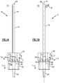
- FIGS 1A, 1B and 2 illustrate an exemplary expandable reamer 10.
- the expandable reamer 10 is an orthopedic surgical device that may be part of a surgical instrumentation set for removing diseased bone from a patient.
- the expandable reamer 10 includes a clutch assembly 12, an inner shaft 14 (best illustrated in Figure 2 ), and an outer tube 16 that generally surrounds the inner shaft 14.
- the inner shaft 14 and the outer tube 16 may include a concentric relationship relative to one another.
- the inner shaft 14 is affixed to the clutch assembly 12 and the outer tube 16 is movable along a longitudinal axis A (see Figure 1B ) of the expandable reamer 10.
- An opposite configuration is also contemplated in which the outer tube 16 is affixed and the inner shaft 14 is moveable along the longitudinal axis A. Movement of either the inner shaft 14 or the outer tube 16 relative to the other of the inner shaft 14 and the outer tube 16 positions a cutting blade 18 for reaming diseased tissue, as discussed in greater detail below.
- the expandable reamer may include one or more cutting blades 18.
- a single cutting blade 18 is shown.
- multiple cutting blades could also be provided (see, e.g., the embodiment of Figures 10A, 10B , 11A and 11B ).
- the cutting blade 18 may be attached to a distal end portion 21 of the inner shaft 14, such as with a pin 22 (i.e., the cutting blade 18 is hinged to the inner shaft 14, see Figures 2 , 3A and 3B ).
- the cutting blade 18 may be incrementally advanced through a window 20 (best illustrated in Figures 3A and 3B ) disposed at a distal end portion 24 of the outer tube 16 to create a retrograded socket in bone that can be filled with biologics.
- the window 20 extends through a sidewall 69 of the outer tube 16 such that the cutting blade 18 is exposed outside of the outer tube 16 through the sidewall 69.
- a cap 26 may be welded or otherwise affixed to a distal-most portion 28 of the outer tube 16 such that the outer tube 16 includes at least one closed end.
- the expandable reamer 10 provides an atraumatic device that substantially reduces risk of inadvertent damage to surrounding tissue during positioning of the expandable reamer 10.
- the cutting blade 18 of the expandable reamer 10 may be advanced radially outward from the outer tube 16 to a cutting position P2 (see Figure 1B ) that is configured to prepare a socket in bone. In the cutting position P2, the cutting blade 18 is non-parallel to the longitudinal axis A and is exposed outside of the outer tube 16.
- the clutch assembly 12 of the expandable reamer 10 includes a threaded hub 30, a clutch hub 32 and a connector 34, such as a Hudson connector for connecting to powered equipment.
- the threaded hub 30 and the clutch hub 32 may be disengaged from one another to advance or retract the cutting blade 18.
- the clutch hub 32 may be moved in a Y direction (e.g., away from the threaded hub 30) to overcome a biasing force of a spring 36 located within the clutch hub 32 to disengage the clutch hub 32 from the threaded hub 30.
- teeth 38 of the clutch hub 32 are removed from recesses 40 of the threaded hub 30 (or vice versa) such that the threaded hub 30 may be turned in the Z direction to either advance or retract the cutting blade 18 between the positions P1 and P2. It should be understood that the cutting blade 18 could be incrementally advanced to any position between positions P1 and P2.
- a distance D between each tooth/recess 38, 40 of the threaded hub 30 and/or the clutch hub 32 may correspond to a specific radially outward advancement of the cutting blade 18.
- the cutting blade 18 may be incrementally advanced or retracted.
- the cutting blade 18 is incrementally advanceable by a distance of between 7 and 10 millimeters (.276 to .394 inches).
- other advancement and retraction distances are also contemplated as within the scope of this disclosure.
- the outer tube 16 includes a threaded proximal end portion 42 that is received by a corresponding threaded portion (not shown) of the threaded hub 30.
- the inner shaft 14 may include a connector 44 for attaching the inner shaft 14 to the threaded hub 30.
- the threaded hub 30 is pinned to the connector 44. Turning the threaded hub 30 in the Z direction moves the threaded hub 30 relative to the threaded proximal end portion 42 in order to axially advance or retract the outer tube 16 relative to the threaded hub 30.
- axial (i.e., linear) movement of the outer tube 16 (which is caused by rotational movement of the threaded hub 30) can be converted to rotational movement of the cutting blade 18 to position the cutting blade 18 in the cutting position P2.
- the outer tube 16 may include a deflection pin 46 that deflects a tip 51 of the cutting blade 18 radially outwardly from the window 20.
- a tapered edge 48 of the cutting blade 18 may contact the deflection pin 46 during linear movement of the outer tube 16 to expose the cutting blade 18.
- the deflection pin 46 acts as a ramp to cause the cutting blade 18 to rotate about an axis that extends through the pin 22, thereby incrementally advancing the cutting blade 18 radially outwardly from the window 20 to the cutting position P2 (see Figures 1B and 3B ).
- the outer tube 16 of the expandable reamer 10 may additionally include a guide pin 45 that is received within a slot 47 of the inner shaft 14 to guide the outer tube 16 as it moves relative to the inner shaft 14.
- Figures 4 through 9 schematically illustrate an example method for removing diseased bone using the expandable reamer 10 described above and illustrated by Figures 1A, 1B , 2 , 3A and 3B .
- the exemplary expandable reamer 10 provides a cutting blade 18 that can be incrementally controlled, thus controlling the size of a socket that is formed in bone. It should be understood that the method described herein and shown in Figures 4, 5, 6 , 7, 8 and 9 may include a greater or fewer number of steps and that the steps could be performed in a different order within the scope of this disclosure.
- the method begins by inserting a guide pin 50 into a bone 52.
- the bone 52 is a femur that includes a femoral head 54, although the method may be beneficially used elsewhere in a patient.
- a surgeon or other person of ordinary skill in the art would be able to select an appropriate positioning and/or placement of the guide pin 50 and could use fluoroscopic guidance and/or a targeting guide to achieve proper placement within the bone 52.
- the guide pin 50 is inserted into diseased bone 56 (i.e., a lesion).
- the guide pin 50 is positioned such that it does not pierce the endosteal surface of the femoral head 54.
- the method may be performed subchondrally.
- a cannulated drill bit 58 is placed over the guide pin 50 to ream a tunnel 60 into the bone 52, as shown in Figure 5 .
- the size of the guide pin 50 and the cannulated drill bit 58 may vary depending upon the size of the patient, among other criteria. Once the bone 52 has been reamed, the cannulated drill bit 58 and guide pin 50 may be removed.
- the expandable reamer 10 may be passed into the tunnel 60 and positioned within the bone 52 such that it extends into the diseased bone 56.
- the cutting blade 18 of the expandable reamer 10 is concealed inside of the outer tube 16 (see position P1 of Figures 1A and 3A ).
- the tunnel 60 could alternatively be formed without using the guide pin 50.
- the cutting blade 18 of the expandable reamer 10 may next be incrementally to a cutting position.
- the cutting blade 18 can be advanced by disengaging the clutch hub 32 from the threaded hub 30 and subsequently turning the threaded hub in the Z direction to effectuate axial movement of the outer tube 16, which is converted to rotational movement of the cutting blade 18 by the deflection pin 46 (see Figures 3A and 3B ) to position the cutting blade 18 in the desired cutting position.
- the desired cutting position may vary depending on the amount of diseased bone 56.
- the entire expandable reamer 10 may then be rotated, such as with power equipment (not shown), to create a retrograded socket 62 in the bone 52 with the cutting blade 18, thereby removing the diseased bone 56.
- the cutting blade 18 may then be retracted (by turning the threaded hub 30 in an opposite direction) and the expandable reamer 10 removed from the bone 52 after the socket 62 has been adequately formed as shown in Figure 8 .
- the tunnel 60 and the socket 62 may be aspirated, such as with a combination of suction and irrigation, to remove any debrided tissue that may exist after reaming.
- the tunnel 60 and the socket 62 may be backfilled with a biologic 64.
- the biologic 64 could include a graft, a bone graft, calcium phosphate bone cement, or any other known biologic material.
- the biologic 64 is injected with a needle 66 working from the socket 62 toward the tunnel 60.
- the tunnel 60 and the socket 62 are completely filled with the biologic 64.
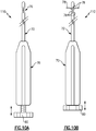
- FIGS 10A and 10B illustrate another exemplary expandable reamer 110.
- the expandable reamer 110 could be used in place of the expandable reamer 10 when performing the method shown in Figures 4 through 9 , or some other similar method, for removing diseased bone.
- the expandable reamer 110 includes a handle 70 and a tube 72 that extends from the handle 70.
- the handle 70 and the tube 72 are cannulated along their entire lengths.
- the tube 72 includes a plurality of windows 76.
- a plurality of cutting blades 78 are positioned inside of the tube 72 and may be incrementally advanced to protrude from the windows 76 in order to ream a socket in bone.
- the cutting blades 78 are expandable nitinol wires that have a shape memory.
- the handle 70 includes an actuator 80 that can be moved into the handle 70 (or vice versa) to position the cutting blades 78 radially outwardly from the windows 76 (i.e., a cutting position in which the cutting blades 78 are transverse to the tube 72). Movement of the actuator 80 in an opposite direction returns the cutting blades 78 to a straight position inside of the tube 72 (i.e., a closed position in which the cutting blades 78 are generally parallel to the tube 72).
- the actuator 80 can also be turned to adjust the shape of the cutting blades 78.
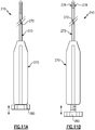
- Figures 11A and 11B illustrate yet another exemplary expandable reamer 210 that can be used to remove diseased bone.
- the expandable reamer 210 includes a handle 270, and an outer tube 272 and an inner shaft 273 that extend from the handle 270.
- the outer tube 272 generally surrounds the inner shaft 273.
- the handle 270 and the outer tube 272 may be cannulated along their entire lengths.
- the inner shaft 273 can include a plurality of cutting blades 278 that may be incrementally advanced to protrude radially outward from the outer tube 272 in order to ream a socket in bone.
- the cutting blades 278 are expandable nitinol wires that have a shape memory.
- the handle 270 includes an actuator 280 that can be moved away from the handle 270 (or vice versa) to move the outer tube 272, thereby positioning the cutting blades 278 radially outwardly to a cutting position.
- movement of the outer tube 272 causes the cutting blades 278 to spring outwardly. Movement of the actuator 280 in an opposite direction returns the cutting blades 278 to a straight position inside of the outer tube 272 (i.e., a closed position).
Landscapes
- Health & Medical Sciences (AREA)
- Surgery (AREA)
- Life Sciences & Earth Sciences (AREA)
- Orthopedic Medicine & Surgery (AREA)
- Biomedical Technology (AREA)
- Nuclear Medicine, Radiotherapy & Molecular Imaging (AREA)
- Engineering & Computer Science (AREA)
- Heart & Thoracic Surgery (AREA)
- Medical Informatics (AREA)
- Molecular Biology (AREA)
- Animal Behavior & Ethology (AREA)
- General Health & Medical Sciences (AREA)
- Public Health (AREA)
- Veterinary Medicine (AREA)
- Oral & Maxillofacial Surgery (AREA)
- Dentistry (AREA)
- Surgical Instruments (AREA)
Abstract
Description
- This disclosure relates to an orthopedic surgical device, and more particularly to an expandable reamer that can be introduced into a bone tunnel to remove areas of diseased bone.
- Diseased areas of bone may need removed from patients suffering from bone degeneration. For example, treatment of Avascular Necrosis (AVN) of the hip is often performed on patients that may otherwise face prosthetic joint arthroplasty, which can be a relatively invasive procedure. Core decompression procedures have been used to remove areas of diseased bone. However, efforts have continued to develop improved procedures for removing areas of diseased bone.
- A surgical device according to an exemplary aspect of the present disclosure includes, among other things, a tube and a cutting blade movable between a first position in which the cutting blade is concealed inside the tube and a second position in which the cutting blade is exposed through a sidewall of the tube.
- In a further non-limiting embodiment of the foregoing surgical device, a shaft is surrounded by the tube.
- In a further non-limiting embodiment of either of the foregoing surgical devices, one of the tube and the shaft is movable relative to the other of the tube and the shaft.
- In a further non-limiting embodiment of any of the foregoing surgical devices, a plurality of cutting blades are moveable to a cutting position radially outward of the tube.
- In a further non-limiting embodiment of any of the foregoing surgical devices, the tube includes a window disposed through the sidewall and the cutting blade is incrementally advanced though the window to expose the cutting blade.
- In a further non-limiting embodiment of any of the foregoing surgical devices, a clutch assembly is configured to move the cutting blade between the first position and the second position.
- In a further non-limiting embodiment of any of the foregoing surgical devices, the clutch assembly includes a threaded hub and a clutch hub disengageable from the threaded hub.
- In a further non-limiting embodiment of any of the foregoing surgical devices, the tube includes a deflection pin configured to deflect the cutting blade radially outward of the tube.
- In a further non-limiting embodiment of any of the foregoing surgical devices, the tube is connected to a handle.
- In a further non-limiting embodiment of any of the foregoing surgical devices, the cutting blade includes nitinol wires having a shape memory.
- In a further non-limiting embodiment of any of the foregoing surgical devices, an actuator is configured to move the cutting blade between the first position and the second position.
- An expandable reamer according to another exemplary aspect of the present disclosure includes, among other things, a tube and at least one cutting blade configured to incrementally advance to a cutting position radially outward from the tube to create a socket in bone.
- In a further non-limiting embodiment of the foregoing expandable reamer, a shaft has a concentric relationship with the tube.
- In a further non-limiting embodiment of either of the foregoing expandable reamers, the cutting blade is hinged to the shaft.
- In a further non-limiting embodiment of any of the foregoing expandable reamers, the tube includes a guide pin received by a slot of the shaft to guide the tube as it moves relative to the shaft.
- A method for removing diseased bone, according to another exemplary aspect of the present disclosure includes, among other things, positioning a surgical device relative to diseased bone, the surgical device including at least one cutting blade that is concealed inside the surgical device during the step of positioning, and incrementally advancing the at least one cutting blade to position the at least one cutting blade into a cutting position relative to the diseased bone.
- In a further non-limiting embodiment of the foregoing method, the method includes the step of rotating the surgical device to remove the diseased bone.
- In a further non-limiting embodiment of either of the foregoing methods, the method includes reaming a tunnel into a bone that includes the diseased bone prior to the step of positioning.
- In a further non-limiting embodiment of any of the foregoing methods, the method includes backfilling the tunnel with a biologic after the step of incrementally advancing the at least one cutting blade.
- In a further non-limiting embodiment of any of the foregoing methods, the step of incrementally advancing includes axially moving a tube or shaft of the surgical device to rotationally move the at least one cutting blade to the cutting position.
- The embodiments, examples and alternatives of the preceding paragraphs, the claims, or the following description and drawings, including any of their various aspects or respective individual features, may be taken independently or in any combination. Features described in connection with one embodiment are applicable to all embodiments, unless such features are incompatible.
- The various features and advantages of this disclosure will become apparent to those skilled in the art from the following detailed description. The drawings that accompany the detailed description can be briefly described as follows.
- The invention will now be further described by reference to the following non-limiting clauses.
- Clause 1. A surgical device, comprising:
- a tube; and
- a cutting blade movable between a first position in which said cutting blade is concealed inside said tube and a second position in which said cutting blade is exposed through a sidewall of said tube.
- Clause 2. The surgical device as recited in clause 1, comprising a shaft surrounded by said tube.
- Clause 3. The surgical device as recited in clause 2, wherein one of said tube and said shaft is movable relative to the other of said tube and said shaft.
- Clause 4. The surgical device as recited in clause 1, 2 or 3, comprising a plurality of cutting blades moveable to a cutting position radially outward of said tube.
- Clause 5. The surgical device as recited in any preceding clause, wherein said tube includes a window disposed through said sidewall and said cutting blade is incrementally advanced though said window to expose said cutting blade.
- Clause 6. The surgical device as recited in any preceding clause, comprising a clutch assembly configured to move said cutting blade between said first position and said second position, and optionally
said clutch assembly includes a threaded hub and a clutch hub disengageable from said threaded hub. - Clause 7. The surgical device as recited in any preceding clause, wherein said tube includes a deflection pin configured to deflect said cutting blade radially outward of said tube.
- Clause 8. The surgical device as recited in any preceding clause, wherein said tube is connected to a handle.
- Clause 9. The surgical device as recited in any preceding clause, wherein said cutting blade includes nitinol wires having a shape memory.
-
Clause 10. The surgical device as recited in any preceding clause, comprising an actuator configured to move said cutting blade between said first position and said second position. - Clause 11. The surgical device as recited in any preceding clause, wherein the surgical device is an expandable reamer; and the at least one cutting blade is configured to incrementally advance to a cutting position radially outward from said tube to create a socket in bone.
-
Clause 12. An expandable reamer, comprising: - a tube; and
- at least one cutting blade configured to incrementally advance to a cutting position radially outward from said tube to create a socket in bone.
- Clause 13. The expandable reamer as recited in
clause 11 or 12, comprising a shaft having a concentric relationship with said tube. -
Clause 14. The expandable reamer as recited in clause 13, wherein said cutting blade is hinged to said shaft. - Clause 15. The expandable reamer as recited in
clause 13 or 14, wherein said tube includes a guide pin received by a slot of said shaft to guide said tube as it moves relative to said shaft. -
-
Figures 1A and 1B illustrate an exemplary expandable reamer. -
Figure 2 illustrates an exploded view of the expandable reamer ofFigures 1A and 1B . -
Figures 3A and 3B illustrate additional features of an expandable reamer. -
Figures 4, 5, 6 ,7, 8 and 9 schematically illustrate an exemplary method of removing areas of diseased bone. -
Figures 10A and 10B illustrate another exemplary expandable reamer. -
Figures 11A and 11B illustrate yet another exemplary expandable reamer. - Among other features, this disclosure relates to a surgical device, such as an expandable reamer, that can be introduced through a bone tunnel to remove areas of diseased bone. In one non-limiting embodiment, the expandable reamers described by this disclosure can be used to treat Avascular Necrosis (AVN) of the hip. However, this disclosure is not limited to the treatment of AVN and could extend to other treatments, such as Osteochondritis Dissecans (OCD) of the knee or any other treatment requiring the removal of diseased bone in either human or animal patients.
-
Figures 1A, 1B and2 illustrate an exemplaryexpandable reamer 10. Theexpandable reamer 10 is an orthopedic surgical device that may be part of a surgical instrumentation set for removing diseased bone from a patient. In one embodiment, theexpandable reamer 10 includes aclutch assembly 12, an inner shaft 14 (best illustrated inFigure 2 ), and anouter tube 16 that generally surrounds theinner shaft 14. For example, theinner shaft 14 and theouter tube 16 may include a concentric relationship relative to one another. - In one non-limiting embodiment, the
inner shaft 14 is affixed to theclutch assembly 12 and theouter tube 16 is movable along a longitudinal axis A (seeFigure 1B ) of theexpandable reamer 10. An opposite configuration is also contemplated in which theouter tube 16 is affixed and theinner shaft 14 is moveable along the longitudinal axis A. Movement of either theinner shaft 14 or theouter tube 16 relative to the other of theinner shaft 14 and theouter tube 16 positions acutting blade 18 for reaming diseased tissue, as discussed in greater detail below. - The expandable reamer may include one or
more cutting blades 18. In this embodiment, asingle cutting blade 18 is shown. However, multiple cutting blades could also be provided (see, e.g., the embodiment ofFigures 10A, 10B ,11A and 11B ). - The
cutting blade 18 may be attached to adistal end portion 21 of theinner shaft 14, such as with a pin 22 (i.e., thecutting blade 18 is hinged to theinner shaft 14, seeFigures 2 ,3A and 3B ). In one embodiment, thecutting blade 18 may be incrementally advanced through a window 20 (best illustrated inFigures 3A and 3B ) disposed at adistal end portion 24 of theouter tube 16 to create a retrograded socket in bone that can be filled with biologics. In one embodiment, thewindow 20 extends through asidewall 69 of theouter tube 16 such that thecutting blade 18 is exposed outside of theouter tube 16 through thesidewall 69. - A cap 26 (see
Figure 2 ) may be welded or otherwise affixed to adistal-most portion 28 of theouter tube 16 such that theouter tube 16 includes at least one closed end. In this way, in a closed position P1 of the cutting blade 18 (seeFigure 1A ), theexpandable reamer 10 provides an atraumatic device that substantially reduces risk of inadvertent damage to surrounding tissue during positioning of theexpandable reamer 10. Thecutting blade 18 of theexpandable reamer 10 may be advanced radially outward from theouter tube 16 to a cutting position P2 (seeFigure 1B ) that is configured to prepare a socket in bone. In the cutting position P2, thecutting blade 18 is non-parallel to the longitudinal axis A and is exposed outside of theouter tube 16. - In one embodiment, the
clutch assembly 12 of theexpandable reamer 10 includes a threadedhub 30, aclutch hub 32 and aconnector 34, such as a Hudson connector for connecting to powered equipment. The threadedhub 30 and theclutch hub 32 may be disengaged from one another to advance or retract thecutting blade 18. For example, theclutch hub 32 may be moved in a Y direction (e.g., away from the threaded hub 30) to overcome a biasing force of aspring 36 located within theclutch hub 32 to disengage theclutch hub 32 from the threadedhub 30. When disengaged,teeth 38 of theclutch hub 32 are removed fromrecesses 40 of the threaded hub 30 (or vice versa) such that the threadedhub 30 may be turned in the Z direction to either advance or retract thecutting blade 18 between the positions P1 and P2. It should be understood that thecutting blade 18 could be incrementally advanced to any position between positions P1 and P2. - A distance D between each tooth/
recess hub 30 and/or theclutch hub 32 may correspond to a specific radially outward advancement of thecutting blade 18. In other words, thecutting blade 18 may be incrementally advanced or retracted. In one non-limiting embodiment, thecutting blade 18 is incrementally advanceable by a distance of between 7 and 10 millimeters (.276 to .394 inches). However, other advancement and retraction distances are also contemplated as within the scope of this disclosure. - In one embodiment, best illustrated in
Figure 2 , theouter tube 16 includes a threadedproximal end portion 42 that is received by a corresponding threaded portion (not shown) of the threadedhub 30. Theinner shaft 14 may include aconnector 44 for attaching theinner shaft 14 to the threadedhub 30. In one embodiment, the threadedhub 30 is pinned to theconnector 44. Turning the threadedhub 30 in the Z direction moves the threadedhub 30 relative to the threadedproximal end portion 42 in order to axially advance or retract theouter tube 16 relative to the threadedhub 30. - Referring to
Figures 3A and 3B , axial (i.e., linear) movement of the outer tube 16 (which is caused by rotational movement of the threaded hub 30) can be converted to rotational movement of thecutting blade 18 to position thecutting blade 18 in the cutting position P2. Theouter tube 16 may include adeflection pin 46 that deflects a tip 51 of thecutting blade 18 radially outwardly from thewindow 20. For example, atapered edge 48 of thecutting blade 18 may contact thedeflection pin 46 during linear movement of theouter tube 16 to expose thecutting blade 18. In other words, thedeflection pin 46 acts as a ramp to cause thecutting blade 18 to rotate about an axis that extends through thepin 22, thereby incrementally advancing thecutting blade 18 radially outwardly from thewindow 20 to the cutting position P2 (seeFigures 1B and3B ). Theouter tube 16 of theexpandable reamer 10 may additionally include aguide pin 45 that is received within aslot 47 of theinner shaft 14 to guide theouter tube 16 as it moves relative to theinner shaft 14. -
Figures 4 through 9 schematically illustrate an example method for removing diseased bone using theexpandable reamer 10 described above and illustrated byFigures 1A, 1B ,2 ,3A and 3B . The exemplaryexpandable reamer 10 provides acutting blade 18 that can be incrementally controlled, thus controlling the size of a socket that is formed in bone. It should be understood that the method described herein and shown inFigures 4, 5, 6 ,7, 8 and 9 may include a greater or fewer number of steps and that the steps could be performed in a different order within the scope of this disclosure. - In one non-limiting embodiment, as illustrated by
Figure 4 , the method begins by inserting aguide pin 50 into abone 52. In this embodiment, thebone 52 is a femur that includes afemoral head 54, although the method may be beneficially used elsewhere in a patient. A surgeon or other person of ordinary skill in the art would be able to select an appropriate positioning and/or placement of theguide pin 50 and could use fluoroscopic guidance and/or a targeting guide to achieve proper placement within thebone 52. - The
guide pin 50 is inserted into diseased bone 56 (i.e., a lesion). In one embodiment, theguide pin 50 is positioned such that it does not pierce the endosteal surface of thefemoral head 54. In other words, the method may be performed subchondrally. - Once the
guide pin 50 has been positioned, a cannulateddrill bit 58 is placed over theguide pin 50 to ream atunnel 60 into thebone 52, as shown inFigure 5 . The size of theguide pin 50 and the cannulateddrill bit 58 may vary depending upon the size of the patient, among other criteria. Once thebone 52 has been reamed, the cannulateddrill bit 58 andguide pin 50 may be removed. - Next, as illustrated by
Figure 6 , theexpandable reamer 10 may be passed into thetunnel 60 and positioned within thebone 52 such that it extends into thediseased bone 56. During this step of positioning, thecutting blade 18 of theexpandable reamer 10 is concealed inside of the outer tube 16 (see position P1 ofFigures 1A and3A ). Thetunnel 60 could alternatively be formed without using theguide pin 50. - Referring now to
Figure 7 , thecutting blade 18 of theexpandable reamer 10 may next be incrementally to a cutting position. For example, thecutting blade 18 can be advanced by disengaging theclutch hub 32 from the threadedhub 30 and subsequently turning the threaded hub in the Z direction to effectuate axial movement of theouter tube 16, which is converted to rotational movement of thecutting blade 18 by the deflection pin 46 (seeFigures 3A and 3B ) to position thecutting blade 18 in the desired cutting position. The desired cutting position may vary depending on the amount ofdiseased bone 56. - The entire
expandable reamer 10 may then be rotated, such as with power equipment (not shown), to create a retrogradedsocket 62 in thebone 52 with thecutting blade 18, thereby removing thediseased bone 56. Thecutting blade 18 may then be retracted (by turning the threadedhub 30 in an opposite direction) and theexpandable reamer 10 removed from thebone 52 after thesocket 62 has been adequately formed as shown inFigure 8 . Thetunnel 60 and thesocket 62 may be aspirated, such as with a combination of suction and irrigation, to remove any debrided tissue that may exist after reaming. - Finally, as shown in
Figure 9 , thetunnel 60 and thesocket 62 may be backfilled with a biologic 64. The biologic 64 could include a graft, a bone graft, calcium phosphate bone cement, or any other known biologic material. In one embodiment, the biologic 64 is injected with aneedle 66 working from thesocket 62 toward thetunnel 60. In another embodiment, thetunnel 60 and thesocket 62 are completely filled with the biologic 64. -
Figures 10A and 10B illustrate another exemplaryexpandable reamer 110. Theexpandable reamer 110 could be used in place of theexpandable reamer 10 when performing the method shown inFigures 4 through 9 , or some other similar method, for removing diseased bone. Theexpandable reamer 110 includes ahandle 70 and atube 72 that extends from thehandle 70. In one embodiment, thehandle 70 and thetube 72 are cannulated along their entire lengths. Thetube 72 includes a plurality ofwindows 76. A plurality of cuttingblades 78 are positioned inside of thetube 72 and may be incrementally advanced to protrude from thewindows 76 in order to ream a socket in bone. - In one embodiment, the
cutting blades 78 are expandable nitinol wires that have a shape memory. Thehandle 70 includes anactuator 80 that can be moved into the handle 70 (or vice versa) to position thecutting blades 78 radially outwardly from the windows 76 (i.e., a cutting position in which thecutting blades 78 are transverse to the tube 72). Movement of theactuator 80 in an opposite direction returns thecutting blades 78 to a straight position inside of the tube 72 (i.e., a closed position in which thecutting blades 78 are generally parallel to the tube 72). Theactuator 80 can also be turned to adjust the shape of thecutting blades 78. -
Figures 11A and 11B illustrate yet another exemplaryexpandable reamer 210 that can be used to remove diseased bone. In this embodiment, theexpandable reamer 210 includes ahandle 270, and anouter tube 272 and aninner shaft 273 that extend from thehandle 270. Theouter tube 272 generally surrounds theinner shaft 273. Thehandle 270 and theouter tube 272 may be cannulated along their entire lengths. - The
inner shaft 273 can include a plurality of cuttingblades 278 that may be incrementally advanced to protrude radially outward from theouter tube 272 in order to ream a socket in bone. In one embodiment, thecutting blades 278 are expandable nitinol wires that have a shape memory. Thehandle 270 includes anactuator 280 that can be moved away from the handle 270 (or vice versa) to move theouter tube 272, thereby positioning thecutting blades 278 radially outwardly to a cutting position. In one embodiment, movement of theouter tube 272 causes thecutting blades 278 to spring outwardly. Movement of theactuator 280 in an opposite direction returns the cuttingblades 278 to a straight position inside of the outer tube 272 (i.e., a closed position). - Although the different non-limiting embodiments are illustrated as having specific components, the embodiments of this disclosure are not limited to those particular combinations. It is possible to use some of the components or features from any of the non-limiting embodiments in combination with features or components from any of the other non-limiting embodiments.
- It should be understood that like reference numerals identify corresponding or similar elements throughout the several drawings. It should also be understood that although a particular component arrangement is disclosed and illustrated in these exemplary embodiments, other arrangements could also benefit from the teachings of this disclosure.
- The foregoing description shall be interpreted as illustrative and not in any limiting sense. A worker of ordinary skill in the art would understand that certain modifications could come within the scope of this disclosure. For these reasons, the following claims should be studied to determine the true scope and content of this disclosure.
Claims (15)
- A surgical device, comprising:a tube;a shaft surrounded by the tube;a cutting blade incrementally movable toward a cutting position radially outward from the tube; anda clutch assembly configured to move the cutting blade in response to rotational movement of a portion of the clutch assembly, wherein the clutch assembly includes a clutch hub and a threaded hub.
- The surgical device as recited in claim 1, wherein rotational movement of the threaded hub of the clutch assembly causes linear movement of the tube or the shaft which causes rotational movement of the cutting blade.
- The surgical device as recited in claim 1 or 2, wherein the shaft has a concentric relationship with the tube.
- The surgical device as recited in any one of the preceding claims, wherein the cutting blade is hinged to the shaft.
- The surgical device as recited in any one of the preceding claims, wherein the tube includes a window disposed through a sidewall of the tube, and the cutting blade is incrementally advanced through the window to expose the cutting blade.
- The surgical device as recited in any one of the preceding claims, wherein the clutch hub is movable in a direction away from the threaded hub to overcome a biasing force of a spring and disengage the clutch hub from the threaded hub.
- The surgical device as recited in any one of the preceding claims, comprising a deflection pin configured to deflect the cutting blade to a positon that is radially outward of the tube.
- The surgical device as recited in claim 7, wherein the deflection pin is configured to deflect the cutting blade radially outward of the tube as a tapered edge of the cutting blade is moved into contact with the deflection pin.
- The surgical device as recited in any one of the preceding claims, wherein the tube is connected to a handle.
- The surgical device as recited in any one of the preceding claims, wherein the tube includes a guide pin received by a slot of the shaft to guide the tube as it moves relative to the shaft.
- The surgical device as recited in any one of the preceding claims, wherein teeth of one of the threaded hub and the clutch hub are removably received within recesses of the other of the threaded hub and the clutch hub.
- The surgical device as recited in claim 11, wherein a distance between each tooth of the teeth corresponds to a specific radially outward incremental advancement of the cutting blade.
- The surgical device as recited in any one of the preceding claims, comprising a cap affixed to a distal-most portion of the tube.
- The surgical device as recited in any one of the preceding claims, wherein the tube includes a threaded proximal end portion that is received by a corresponding threaded portion of the threaded hub.
- The surgical device as recited in any one of the preceding claims, wherein the shaft includes a connector for attaching the shaft to the threaded hub.
Applications Claiming Priority (3)
| Application Number | Priority Date | Filing Date | Title |
|---|---|---|---|
| US201361774787P | 2013-03-08 | 2013-03-08 | |
| US14/091,902 US10499932B2 (en) | 2013-03-08 | 2013-11-27 | Expandable reamer |
| EP14157959.9A EP2774556B1 (en) | 2013-03-08 | 2014-03-05 | Expandable reamer |
Related Parent Applications (2)
| Application Number | Title | Priority Date | Filing Date |
|---|---|---|---|
| EP14157959.9A Division-Into EP2774556B1 (en) | 2013-03-08 | 2014-03-05 | Expandable reamer |
| EP14157959.9A Division EP2774556B1 (en) | 2013-03-08 | 2014-03-05 | Expandable reamer |
Publications (2)
| Publication Number | Publication Date |
|---|---|
| EP3284419A1 true EP3284419A1 (en) | 2018-02-21 |
| EP3284419B1 EP3284419B1 (en) | 2022-10-26 |
Family
ID=50235991
Family Applications (2)
| Application Number | Title | Priority Date | Filing Date |
|---|---|---|---|
| EP14157959.9A Active EP2774556B1 (en) | 2013-03-08 | 2014-03-05 | Expandable reamer |
| EP17181267.0A Active EP3284419B1 (en) | 2013-03-08 | 2014-03-05 | Expandable reamer |
Family Applications Before (1)
| Application Number | Title | Priority Date | Filing Date |
|---|---|---|---|
| EP14157959.9A Active EP2774556B1 (en) | 2013-03-08 | 2014-03-05 | Expandable reamer |
Country Status (3)
| Country | Link |
|---|---|
| US (4) | US10499932B2 (en) |
| EP (2) | EP2774556B1 (en) |
| JP (2) | JP2014171864A (en) |
Families Citing this family (58)
| Publication number | Priority date | Publication date | Assignee | Title |
|---|---|---|---|---|
| US6610067B2 (en) | 2000-05-01 | 2003-08-26 | Arthrosurface, Incorporated | System and method for joint resurface repair |
| EP2314257B9 (en) | 2000-05-01 | 2013-02-27 | ArthroSurface, Inc. | System for joint resurface repair |
| US7914545B2 (en) | 2002-12-03 | 2011-03-29 | Arthrosurface, Inc | System and method for retrograde procedure |
| US8388624B2 (en) | 2003-02-24 | 2013-03-05 | Arthrosurface Incorporated | Trochlear resurfacing system and method |
| JP2008504107A (en) | 2004-06-28 | 2008-02-14 | アースロサーフィス・インコーポレーテッド | Joint surface replacement system |
| US7828853B2 (en) | 2004-11-22 | 2010-11-09 | Arthrosurface, Inc. | Articular surface implant and delivery system |
| AU2007332787A1 (en) | 2006-12-11 | 2008-06-19 | Arthrosurface Incorporated | Retrograde resection apparatus and method |
| WO2009111481A1 (en) | 2008-03-03 | 2009-09-11 | Arthrosurface Incorporated | Bone resurfacing system and method |
| US10945743B2 (en) | 2009-04-17 | 2021-03-16 | Arthrosurface Incorporated | Glenoid repair system and methods of use thereof |
| CA3064646C (en) | 2009-04-17 | 2023-01-03 | Arthrosurface Incorporated | Glenoid resurfacing system and method |
| WO2010121250A1 (en) | 2009-04-17 | 2010-10-21 | Arthrosurface Incorporated | Glenoid resurfacing system and method |
| BR112012022482A2 (en) | 2010-03-05 | 2016-07-19 | Arthrosurface Inc | tibial surface recomposition system and method. |
| US9498273B2 (en) | 2010-06-02 | 2016-11-22 | Wright Medical Technology, Inc. | Orthopedic implant kit |
| US8608785B2 (en) | 2010-06-02 | 2013-12-17 | Wright Medical Technology, Inc. | Hammer toe implant with expansion portion for retrograde approach |
| US9724140B2 (en) | 2010-06-02 | 2017-08-08 | Wright Medical Technology, Inc. | Tapered, cylindrical cruciform hammer toe implant and method |
| US9066716B2 (en) | 2011-03-30 | 2015-06-30 | Arthrosurface Incorporated | Suture coil and suture sheath for tissue repair |
| EP2804565B1 (en) | 2011-12-22 | 2018-03-07 | Arthrosurface Incorporated | System for bone fixation |
| DE112013003358T5 (en) | 2012-07-03 | 2015-03-19 | Arthrosurface, Inc. | System and procedure for joint surface replacement and repair |
| US10357259B2 (en) * | 2012-12-05 | 2019-07-23 | Smith & Nephew, Inc. | Surgical instrument |
| US8945232B2 (en) | 2012-12-31 | 2015-02-03 | Wright Medical Technology, Inc. | Ball and socket implants for correction of hammer toes and claw toes |
| US10499932B2 (en) * | 2013-03-08 | 2019-12-10 | Arthrex, Inc. | Expandable reamer |
| US9480574B2 (en) | 2013-03-14 | 2016-11-01 | Benvenue Medical, Inc. | Spinal fusion implants and devices and methods for deploying such implants |
| US9492200B2 (en) | 2013-04-16 | 2016-11-15 | Arthrosurface Incorporated | Suture system and method |
| EP3326552B1 (en) | 2013-04-24 | 2023-02-22 | T.A.G. Medical Devices - Agriculture Cooperative Ltd. | Bone material removal devices |
| US9474561B2 (en) | 2013-11-19 | 2016-10-25 | Wright Medical Technology, Inc. | Two-wire technique for installing hammertoe implant |
| US11219466B2 (en) * | 2018-06-06 | 2022-01-11 | Acumed Llc | Orthopedic reamer with expandable cutting head |
| US9545283B2 (en) * | 2013-12-23 | 2017-01-17 | Jmea Corporation | Devices and methods for preparation of vertebral members |
| US9545274B2 (en) | 2014-02-12 | 2017-01-17 | Wright Medical Technology, Inc. | Intramedullary implant, system, and method for inserting an implant into a bone |
| US9498266B2 (en) | 2014-02-12 | 2016-11-22 | Wright Medical Technology, Inc. | Intramedullary implant, system, and method for inserting an implant into a bone |
| US10624748B2 (en) | 2014-03-07 | 2020-04-21 | Arthrosurface Incorporated | System and method for repairing articular surfaces |
| US9931219B2 (en) | 2014-03-07 | 2018-04-03 | Arthrosurface Incorporated | Implant and anchor assembly |
| US11607319B2 (en) | 2014-03-07 | 2023-03-21 | Arthrosurface Incorporated | System and method for repairing articular surfaces |
| US10952872B2 (en) * | 2014-06-12 | 2021-03-23 | Limacorporate S.P.A. | Instrument for the removal of a bone insert and corresponding method |
| US10258484B2 (en) * | 2014-06-12 | 2019-04-16 | Limacorporate S.P.A. | Instrument for the removal of a bone insert and corresponding method |
| US10045803B2 (en) * | 2014-07-03 | 2018-08-14 | Mayo Foundation For Medical Education And Research | Sacroiliac joint fusion screw and method |
| US10314605B2 (en) * | 2014-07-08 | 2019-06-11 | Benvenue Medical, Inc. | Apparatus and methods for disrupting intervertebral disc tissue |
| DE102014214404B3 (en) * | 2014-07-23 | 2015-08-27 | Eberle Gmbh & Co. Kg | Medical instrument for the removal of cancellous bone |
| US9662123B2 (en) * | 2014-07-31 | 2017-05-30 | Amendia, Inc. | Vertical cutter and method of use |
| WO2016043751A1 (en) * | 2014-09-18 | 2016-03-24 | Wright Medical Technology, Inc. | Hammertoe implant and instrument |
| BR122022014776B1 (en) | 2014-10-19 | 2023-12-26 | T.A.G. Medical Devices - Agriculture Cooperative Ltd | SET INCLUDING A GUIDANCE SYSTEM AND DEVICE FOR REMOVING BONE MATERIAL AND METHOD FOR DRILLING A BONE TUNNEL IN A BONE |
| CA2889595C (en) | 2014-12-19 | 2018-01-16 | Wright Medical Technology, Inc. | Intramedullary anchor for interphalangeal arthrodesis |
| US10448959B2 (en) | 2015-04-09 | 2019-10-22 | T.A.G. Medical Devices—Agriculture Cooperative Ltd. | Bone material removal device and a method for use thereof |
| US10743912B2 (en) | 2015-11-17 | 2020-08-18 | Lenkbar, Llc | Surgical tunneling instrument with expandable section |
| US10492800B2 (en) | 2015-11-25 | 2019-12-03 | Lenkbar, Llc | Bone cutting instrument with expandable section |
| EP3413810B1 (en) | 2016-02-11 | 2021-08-18 | T.A.G. Medical Devices - Agriculture Cooperative Ltd. | Bone material removal device |
| US11020132B2 (en) | 2016-04-24 | 2021-06-01 | T.A.G. Medical Devices—Agriculture Cooperative Ltd. | Guiding device and method of using thereof |
| US10751071B2 (en) | 2016-04-25 | 2020-08-25 | Imds Llc | Joint fusion instrumentation and methods |
| US10413332B2 (en) * | 2016-04-25 | 2019-09-17 | Imds Llc | Joint fusion implant and methods |
| US10456145B2 (en) | 2017-05-16 | 2019-10-29 | Arthrex, Inc. | Expandable reamers |
| EP3638132A1 (en) * | 2017-06-12 | 2020-04-22 | ConMed Corporation | Orthopedic drill bit with swiveling head |
| CA3108761A1 (en) | 2017-08-04 | 2019-02-07 | Arthrosurface Incorporated | Multicomponent articular surface implant |
| US11583327B2 (en) | 2018-01-29 | 2023-02-21 | Spinal Elements, Inc. | Minimally invasive interbody fusion |
| WO2019178575A1 (en) | 2018-03-16 | 2019-09-19 | Benvenue Medical, Inc. | Articulated instrumentation and methods of using the same |
| US11737785B2 (en) * | 2018-06-11 | 2023-08-29 | Desarrollos Biomecanicos Innovasan S.L. | Hip or shoulder prosthesis and placement instruments |
| EP3829411B1 (en) | 2018-08-01 | 2024-10-02 | T.A.G. Medical Devices - Agriculture Cooperative Ltd. | Adjustable drilling device |
| GB2609338B (en) | 2019-03-12 | 2023-06-14 | Arthrosurface Inc | Humeral and glenoid articular surface implant systems and methods |
| US20260096824A1 (en) * | 2022-10-13 | 2026-04-09 | Wright Medical Technology, Inc. | Bone Material Harvesting Device Having Radially Expandable And Retractable Shaft |
| WO2026024635A1 (en) * | 2024-07-22 | 2026-01-29 | Tenon Medical, Inc. | Joint fusion preparation assembly and related methods |
Citations (3)
| Publication number | Priority date | Publication date | Assignee | Title |
|---|---|---|---|---|
| US20080114364A1 (en) * | 2006-11-15 | 2008-05-15 | Aoi Medical, Inc. | Tissue cavitation device and method |
| US20110130760A1 (en) * | 2008-07-29 | 2011-06-02 | Depuy International Ltd | Instrument for forming a cavity within a bone |
| US20120271357A1 (en) * | 2011-04-21 | 2012-10-25 | Warsaw Orthopedic, Inc. | Tools and methods for the preparation of the facet joint |
Family Cites Families (21)
| Publication number | Priority date | Publication date | Assignee | Title |
|---|---|---|---|---|
| US1410080A (en) * | 1921-12-01 | 1922-03-21 | Schwahlen Josef | Chuck |
| US3195378A (en) * | 1957-08-07 | 1965-07-20 | Cogsdill Tool Prod | Cutting tool |
| US3008360A (en) * | 1958-03-03 | 1961-11-14 | Cogsdill Tool Prod | Cutting tool |
| DE2349998C2 (en) * | 1973-10-05 | 1982-12-02 | Artur Dr.H.C. 7244 Waldachtal Fischer | Drilling unit for producing an undercut in the borehole |
| US4475852A (en) * | 1981-12-24 | 1984-10-09 | Santrade Ltd. | Retractable rotary cutting tool |
| DE3839617A1 (en) * | 1988-11-24 | 1990-05-31 | Fischer Artur Werke Gmbh | DEVICE FOR PRODUCING AN UNDERCUT IN A DRILL HOLE |
| US5591170A (en) | 1994-10-14 | 1997-01-07 | Genesis Orthopedics | Intramedullary bone cutting saw |
| US5928239A (en) * | 1998-03-16 | 1999-07-27 | University Of Washington | Percutaneous surgical cavitation device and method |
| US6383188B2 (en) * | 2000-02-15 | 2002-05-07 | The Spineology Group Llc | Expandable reamer |
| US20020068974A1 (en) * | 2000-07-21 | 2002-06-06 | Kuslich Stephen D. | Expandable porous mesh bag device and methods of use for reduction, filling, fixation and supporting of bone |
| AU2003230740B2 (en) * | 2002-11-08 | 2008-10-09 | Warsaw Orthopedic, Inc. | Transpedicular intervertebral disk access methods and devices |
| US7914545B2 (en) | 2002-12-03 | 2011-03-29 | Arthrosurface, Inc | System and method for retrograde procedure |
| US7429264B2 (en) * | 2004-06-15 | 2008-09-30 | Warsaw Orthopedic, Inc. | Minimally invasive deployable cutting instrument |
| US20060057184A1 (en) | 2004-09-16 | 2006-03-16 | Nycz Jeffrey H | Process to treat avascular necrosis (AVN) with osteoinductive materials |
| US20060241629A1 (en) | 2005-04-07 | 2006-10-26 | Zimmer Technology, Inc. | Expandable reamer |
| US8652139B2 (en) * | 2007-05-02 | 2014-02-18 | Arthrex, Inc. | Flip retrograde cutting instrument |
| US8591514B2 (en) | 2007-05-02 | 2013-11-26 | Arthrex, Inc. | Retrograde cutter with rotating blade |
| TWI579007B (en) | 2010-07-02 | 2017-04-21 | 艾格諾福斯保健公司 | Use of bone regenerative material |
| JP5819669B2 (en) * | 2011-08-04 | 2015-11-24 | スミス アンド ネフュー インコーポレーテッド | Cutting tools |
| WO2013026920A1 (en) * | 2011-08-25 | 2013-02-28 | Endocontrol | Surgical instrument with disengageable handle |
| US10499932B2 (en) * | 2013-03-08 | 2019-12-10 | Arthrex, Inc. | Expandable reamer |
-
2013
- 2013-11-27 US US14/091,902 patent/US10499932B2/en active Active
-
2014
- 2014-01-29 JP JP2014014241A patent/JP2014171864A/en active Pending
- 2014-03-05 EP EP14157959.9A patent/EP2774556B1/en active Active
- 2014-03-05 EP EP17181267.0A patent/EP3284419B1/en active Active
-
2018
- 2018-05-17 JP JP2018095352A patent/JP6578409B2/en active Active
-
2019
- 2019-11-18 US US16/686,555 patent/US11517329B2/en active Active
-
2022
- 2022-11-08 US US17/982,612 patent/US12303146B2/en active Active
-
2025
- 2025-04-28 US US19/190,889 patent/US20250248717A1/en active Pending
Patent Citations (3)
| Publication number | Priority date | Publication date | Assignee | Title |
|---|---|---|---|---|
| US20080114364A1 (en) * | 2006-11-15 | 2008-05-15 | Aoi Medical, Inc. | Tissue cavitation device and method |
| US20110130760A1 (en) * | 2008-07-29 | 2011-06-02 | Depuy International Ltd | Instrument for forming a cavity within a bone |
| US20120271357A1 (en) * | 2011-04-21 | 2012-10-25 | Warsaw Orthopedic, Inc. | Tools and methods for the preparation of the facet joint |
Also Published As
| Publication number | Publication date |
|---|---|
| US20250248717A1 (en) | 2025-08-07 |
| US20200078028A1 (en) | 2020-03-12 |
| US11517329B2 (en) | 2022-12-06 |
| JP2014171864A (en) | 2014-09-22 |
| JP2018153668A (en) | 2018-10-04 |
| US10499932B2 (en) | 2019-12-10 |
| US12303146B2 (en) | 2025-05-20 |
| US20140257297A1 (en) | 2014-09-11 |
| EP2774556B1 (en) | 2017-11-01 |
| JP6578409B2 (en) | 2019-09-18 |
| EP3284419B1 (en) | 2022-10-26 |
| EP2774556A1 (en) | 2014-09-10 |
| US20230060840A1 (en) | 2023-03-02 |
Similar Documents
| Publication | Publication Date | Title |
|---|---|---|
| US12303146B2 (en) | Expandable reamer | |
| CN105310742B (en) | Retrograde cutting instrument with adjustable limit setting | |
| EP2236100B1 (en) | Microfracture instrument | |
| KR101333472B1 (en) | A surgical drill, a set of surgical drills, a system for cutting bone and a method for removing bone | |
| US20130165935A1 (en) | Expandable retrograde drill | |
| EP2967584B1 (en) | Retro guidewire reamer | |
| EP1549230B1 (en) | A reamer assembly | |
| JP5497032B2 (en) | Instruments that form cavities inside bones | |
| EP1535579A2 (en) | Expandable reamer | |
| US20160199072A1 (en) | Bone removal under direct visualization | |
| AU2017268657B2 (en) | Methods and devices for cutting and removing tissue from a body | |
| EP3376972B1 (en) | Surgical tunneling instrument with expandable section | |
| CN110461256B (en) | Guiding osteotome | |
| CN220069811U (en) | Femoral head necrosis removing device | |
| WO2013179002A1 (en) | A trial instrument for use in orthopaedic surgery |
Legal Events
| Date | Code | Title | Description |
|---|---|---|---|
| PUAI | Public reference made under article 153(3) epc to a published international application that has entered the european phase |
Free format text: ORIGINAL CODE: 0009012 |
|
| STAA | Information on the status of an ep patent application or granted ep patent |
Free format text: STATUS: THE APPLICATION HAS BEEN PUBLISHED |
|
| AC | Divisional application: reference to earlier application |
Ref document number: 2774556 Country of ref document: EP Kind code of ref document: P |
|
| AK | Designated contracting states |
Kind code of ref document: A1 Designated state(s): AL AT BE BG CH CY CZ DE DK EE ES FI FR GB GR HR HU IE IS IT LI LT LU LV MC MK MT NL NO PL PT RO RS SE SI SK SM TR |
|
| STAA | Information on the status of an ep patent application or granted ep patent |
Free format text: STATUS: REQUEST FOR EXAMINATION WAS MADE |
|
| 17P | Request for examination filed |
Effective date: 20180821 |
|
| RBV | Designated contracting states (corrected) |
Designated state(s): AL AT BE BG CH CY CZ DE DK EE ES FI FR GB GR HR HU IE IS IT LI LT LU LV MC MK MT NL NO PL PT RO RS SE SI SK SM TR |
|
| STAA | Information on the status of an ep patent application or granted ep patent |
Free format text: STATUS: EXAMINATION IS IN PROGRESS |
|
| 17Q | First examination report despatched |
Effective date: 20200706 |
|
| GRAP | Despatch of communication of intention to grant a patent |
Free format text: ORIGINAL CODE: EPIDOSNIGR1 |
|
| STAA | Information on the status of an ep patent application or granted ep patent |
Free format text: STATUS: GRANT OF PATENT IS INTENDED |
|
| RIC1 | Information provided on ipc code assigned before grant |
Ipc: A61B 17/32 20060101ALN20220412BHEP Ipc: A61B 17/16 20060101AFI20220412BHEP |
|
| INTG | Intention to grant announced |
Effective date: 20220506 |
|
| GRAS | Grant fee paid |
Free format text: ORIGINAL CODE: EPIDOSNIGR3 |
|
| GRAA | (expected) grant |
Free format text: ORIGINAL CODE: 0009210 |
|
| STAA | Information on the status of an ep patent application or granted ep patent |
Free format text: STATUS: THE PATENT HAS BEEN GRANTED |
|
| AC | Divisional application: reference to earlier application |
Ref document number: 2774556 Country of ref document: EP Kind code of ref document: P |
|
| AK | Designated contracting states |
Kind code of ref document: B1 Designated state(s): AL AT BE BG CH CY CZ DE DK EE ES FI FR GB GR HR HU IE IS IT LI LT LU LV MC MK MT NL NO PL PT RO RS SE SI SK SM TR |
|
| REG | Reference to a national code |
Ref country code: GB Ref legal event code: FG4D |
|
| REG | Reference to a national code |
Ref country code: CH Ref legal event code: EP |
|
| REG | Reference to a national code |
Ref country code: AT Ref legal event code: REF Ref document number: 1526480 Country of ref document: AT Kind code of ref document: T Effective date: 20221115 |
|
| REG | Reference to a national code |
Ref country code: DE Ref legal event code: R096 Ref document number: 602014085368 Country of ref document: DE |
|
| REG | Reference to a national code |
Ref country code: IE Ref legal event code: FG4D |
|
| REG | Reference to a national code |
Ref country code: LT Ref legal event code: MG9D |
|
| REG | Reference to a national code |
Ref country code: NL Ref legal event code: MP Effective date: 20221026 |
|
| REG | Reference to a national code |
Ref country code: AT Ref legal event code: MK05 Ref document number: 1526480 Country of ref document: AT Kind code of ref document: T Effective date: 20221026 |
|
| PG25 | Lapsed in a contracting state [announced via postgrant information from national office to epo] |
Ref country code: NL Free format text: LAPSE BECAUSE OF FAILURE TO SUBMIT A TRANSLATION OF THE DESCRIPTION OR TO PAY THE FEE WITHIN THE PRESCRIBED TIME-LIMIT Effective date: 20221026 |
|
| PG25 | Lapsed in a contracting state [announced via postgrant information from national office to epo] |
Ref country code: SE Free format text: LAPSE BECAUSE OF FAILURE TO SUBMIT A TRANSLATION OF THE DESCRIPTION OR TO PAY THE FEE WITHIN THE PRESCRIBED TIME-LIMIT Effective date: 20221026 Ref country code: PT Free format text: LAPSE BECAUSE OF FAILURE TO SUBMIT A TRANSLATION OF THE DESCRIPTION OR TO PAY THE FEE WITHIN THE PRESCRIBED TIME-LIMIT Effective date: 20230227 Ref country code: NO Free format text: LAPSE BECAUSE OF FAILURE TO SUBMIT A TRANSLATION OF THE DESCRIPTION OR TO PAY THE FEE WITHIN THE PRESCRIBED TIME-LIMIT Effective date: 20230126 Ref country code: LT Free format text: LAPSE BECAUSE OF FAILURE TO SUBMIT A TRANSLATION OF THE DESCRIPTION OR TO PAY THE FEE WITHIN THE PRESCRIBED TIME-LIMIT Effective date: 20221026 Ref country code: FI Free format text: LAPSE BECAUSE OF FAILURE TO SUBMIT A TRANSLATION OF THE DESCRIPTION OR TO PAY THE FEE WITHIN THE PRESCRIBED TIME-LIMIT Effective date: 20221026 Ref country code: ES Free format text: LAPSE BECAUSE OF FAILURE TO SUBMIT A TRANSLATION OF THE DESCRIPTION OR TO PAY THE FEE WITHIN THE PRESCRIBED TIME-LIMIT Effective date: 20221026 Ref country code: AT Free format text: LAPSE BECAUSE OF FAILURE TO SUBMIT A TRANSLATION OF THE DESCRIPTION OR TO PAY THE FEE WITHIN THE PRESCRIBED TIME-LIMIT Effective date: 20221026 |
|
| PG25 | Lapsed in a contracting state [announced via postgrant information from national office to epo] |
Ref country code: RS Free format text: LAPSE BECAUSE OF FAILURE TO SUBMIT A TRANSLATION OF THE DESCRIPTION OR TO PAY THE FEE WITHIN THE PRESCRIBED TIME-LIMIT Effective date: 20221026 Ref country code: PL Free format text: LAPSE BECAUSE OF FAILURE TO SUBMIT A TRANSLATION OF THE DESCRIPTION OR TO PAY THE FEE WITHIN THE PRESCRIBED TIME-LIMIT Effective date: 20221026 Ref country code: LV Free format text: LAPSE BECAUSE OF FAILURE TO SUBMIT A TRANSLATION OF THE DESCRIPTION OR TO PAY THE FEE WITHIN THE PRESCRIBED TIME-LIMIT Effective date: 20221026 Ref country code: IS Free format text: LAPSE BECAUSE OF FAILURE TO SUBMIT A TRANSLATION OF THE DESCRIPTION OR TO PAY THE FEE WITHIN THE PRESCRIBED TIME-LIMIT Effective date: 20230226 Ref country code: HR Free format text: LAPSE BECAUSE OF FAILURE TO SUBMIT A TRANSLATION OF THE DESCRIPTION OR TO PAY THE FEE WITHIN THE PRESCRIBED TIME-LIMIT Effective date: 20221026 Ref country code: GR Free format text: LAPSE BECAUSE OF FAILURE TO SUBMIT A TRANSLATION OF THE DESCRIPTION OR TO PAY THE FEE WITHIN THE PRESCRIBED TIME-LIMIT Effective date: 20230127 |
|
| REG | Reference to a national code |
Ref country code: DE Ref legal event code: R097 Ref document number: 602014085368 Country of ref document: DE |
|
| PG25 | Lapsed in a contracting state [announced via postgrant information from national office to epo] |
Ref country code: SM Free format text: LAPSE BECAUSE OF FAILURE TO SUBMIT A TRANSLATION OF THE DESCRIPTION OR TO PAY THE FEE WITHIN THE PRESCRIBED TIME-LIMIT Effective date: 20221026 Ref country code: RO Free format text: LAPSE BECAUSE OF FAILURE TO SUBMIT A TRANSLATION OF THE DESCRIPTION OR TO PAY THE FEE WITHIN THE PRESCRIBED TIME-LIMIT Effective date: 20221026 Ref country code: EE Free format text: LAPSE BECAUSE OF FAILURE TO SUBMIT A TRANSLATION OF THE DESCRIPTION OR TO PAY THE FEE WITHIN THE PRESCRIBED TIME-LIMIT Effective date: 20221026 Ref country code: DK Free format text: LAPSE BECAUSE OF FAILURE TO SUBMIT A TRANSLATION OF THE DESCRIPTION OR TO PAY THE FEE WITHIN THE PRESCRIBED TIME-LIMIT Effective date: 20221026 Ref country code: CZ Free format text: LAPSE BECAUSE OF FAILURE TO SUBMIT A TRANSLATION OF THE DESCRIPTION OR TO PAY THE FEE WITHIN THE PRESCRIBED TIME-LIMIT Effective date: 20221026 |
|
| PG25 | Lapsed in a contracting state [announced via postgrant information from national office to epo] |
Ref country code: SK Free format text: LAPSE BECAUSE OF FAILURE TO SUBMIT A TRANSLATION OF THE DESCRIPTION OR TO PAY THE FEE WITHIN THE PRESCRIBED TIME-LIMIT Effective date: 20221026 Ref country code: AL Free format text: LAPSE BECAUSE OF FAILURE TO SUBMIT A TRANSLATION OF THE DESCRIPTION OR TO PAY THE FEE WITHIN THE PRESCRIBED TIME-LIMIT Effective date: 20221026 |
|
| PLBE | No opposition filed within time limit |
Free format text: ORIGINAL CODE: 0009261 |
|
| STAA | Information on the status of an ep patent application or granted ep patent |
Free format text: STATUS: NO OPPOSITION FILED WITHIN TIME LIMIT |
|
| 26N | No opposition filed |
Effective date: 20230727 |
|
| PG25 | Lapsed in a contracting state [announced via postgrant information from national office to epo] |
Ref country code: MC Free format text: LAPSE BECAUSE OF FAILURE TO SUBMIT A TRANSLATION OF THE DESCRIPTION OR TO PAY THE FEE WITHIN THE PRESCRIBED TIME-LIMIT Effective date: 20221026 |
|
| REG | Reference to a national code |
Ref country code: CH Ref legal event code: PL |
|
| PG25 | Lapsed in a contracting state [announced via postgrant information from national office to epo] |
Ref country code: SI Free format text: LAPSE BECAUSE OF FAILURE TO SUBMIT A TRANSLATION OF THE DESCRIPTION OR TO PAY THE FEE WITHIN THE PRESCRIBED TIME-LIMIT Effective date: 20221026 |
|
| REG | Reference to a national code |
Ref country code: BE Ref legal event code: MM Effective date: 20230331 |
|
| PG25 | Lapsed in a contracting state [announced via postgrant information from national office to epo] |
Ref country code: LU Free format text: LAPSE BECAUSE OF NON-PAYMENT OF DUE FEES Effective date: 20230305 |
|
| REG | Reference to a national code |
Ref country code: IE Ref legal event code: MM4A |
|
| PG25 | Lapsed in a contracting state [announced via postgrant information from national office to epo] |
Ref country code: LI Free format text: LAPSE BECAUSE OF NON-PAYMENT OF DUE FEES Effective date: 20230331 Ref country code: IE Free format text: LAPSE BECAUSE OF NON-PAYMENT OF DUE FEES Effective date: 20230305 Ref country code: CH Free format text: LAPSE BECAUSE OF NON-PAYMENT OF DUE FEES Effective date: 20230331 |
|
| PG25 | Lapsed in a contracting state [announced via postgrant information from national office to epo] |
Ref country code: BE Free format text: LAPSE BECAUSE OF NON-PAYMENT OF DUE FEES Effective date: 20230331 |
|
| PG25 | Lapsed in a contracting state [announced via postgrant information from national office to epo] |
Ref country code: IT Free format text: LAPSE BECAUSE OF FAILURE TO SUBMIT A TRANSLATION OF THE DESCRIPTION OR TO PAY THE FEE WITHIN THE PRESCRIBED TIME-LIMIT Effective date: 20221026 |
|
| PG25 | Lapsed in a contracting state [announced via postgrant information from national office to epo] |
Ref country code: BG Free format text: LAPSE BECAUSE OF FAILURE TO SUBMIT A TRANSLATION OF THE DESCRIPTION OR TO PAY THE FEE WITHIN THE PRESCRIBED TIME-LIMIT Effective date: 20221026 |
|
| PG25 | Lapsed in a contracting state [announced via postgrant information from national office to epo] |
Ref country code: BG Free format text: LAPSE BECAUSE OF FAILURE TO SUBMIT A TRANSLATION OF THE DESCRIPTION OR TO PAY THE FEE WITHIN THE PRESCRIBED TIME-LIMIT Effective date: 20221026 |
|
| PG25 | Lapsed in a contracting state [announced via postgrant information from national office to epo] |
Ref country code: CY Free format text: LAPSE BECAUSE OF FAILURE TO SUBMIT A TRANSLATION OF THE DESCRIPTION OR TO PAY THE FEE WITHIN THE PRESCRIBED TIME-LIMIT; INVALID AB INITIO Effective date: 20140305 |
|
| PG25 | Lapsed in a contracting state [announced via postgrant information from national office to epo] |
Ref country code: HU Free format text: LAPSE BECAUSE OF FAILURE TO SUBMIT A TRANSLATION OF THE DESCRIPTION OR TO PAY THE FEE WITHIN THE PRESCRIBED TIME-LIMIT; INVALID AB INITIO Effective date: 20140305 |
|
| PG25 | Lapsed in a contracting state [announced via postgrant information from national office to epo] |
Ref country code: TR Free format text: LAPSE BECAUSE OF FAILURE TO SUBMIT A TRANSLATION OF THE DESCRIPTION OR TO PAY THE FEE WITHIN THE PRESCRIBED TIME-LIMIT Effective date: 20221026 |
|
| PGFP | Annual fee paid to national office [announced via postgrant information from national office to epo] |
Ref country code: FR Payment date: 20251231 Year of fee payment: 13 |
|
| PGFP | Annual fee paid to national office [announced via postgrant information from national office to epo] |
Ref country code: GB Payment date: 20260106 Year of fee payment: 13 |
|
| PGFP | Annual fee paid to national office [announced via postgrant information from national office to epo] |
Ref country code: DE Payment date: 20260102 Year of fee payment: 13 |