EP3284385B1 - Spraying arm assembly of dish washer and dish washer having same - Google Patents
Spraying arm assembly of dish washer and dish washer having same Download PDFInfo
- Publication number
- EP3284385B1 EP3284385B1 EP15889044.2A EP15889044A EP3284385B1 EP 3284385 B1 EP3284385 B1 EP 3284385B1 EP 15889044 A EP15889044 A EP 15889044A EP 3284385 B1 EP3284385 B1 EP 3284385B1
- Authority
- EP
- European Patent Office
- Prior art keywords
- spray arm
- gear
- fixed gear
- main
- arm assembly
- Prior art date
- Legal status (The legal status is an assumption and is not a legal conclusion. Google has not performed a legal analysis and makes no representation as to the accuracy of the status listed.)
- Active
Links
Images


Classifications
-
- A—HUMAN NECESSITIES
- A47—FURNITURE; DOMESTIC ARTICLES OR APPLIANCES; COFFEE MILLS; SPICE MILLS; SUCTION CLEANERS IN GENERAL
- A47L—DOMESTIC WASHING OR CLEANING; SUCTION CLEANERS IN GENERAL
- A47L15/00—Washing or rinsing machines for crockery or tableware
- A47L15/14—Washing or rinsing machines for crockery or tableware with stationary crockery baskets and spraying devices within the cleaning chamber
- A47L15/18—Washing or rinsing machines for crockery or tableware with stationary crockery baskets and spraying devices within the cleaning chamber with movably-mounted spraying devices
- A47L15/22—Rotary spraying devices
-
- A—HUMAN NECESSITIES
- A47—FURNITURE; DOMESTIC ARTICLES OR APPLIANCES; COFFEE MILLS; SPICE MILLS; SUCTION CLEANERS IN GENERAL
- A47L—DOMESTIC WASHING OR CLEANING; SUCTION CLEANERS IN GENERAL
- A47L15/00—Washing or rinsing machines for crockery or tableware
- A47L15/14—Washing or rinsing machines for crockery or tableware with stationary crockery baskets and spraying devices within the cleaning chamber
- A47L15/18—Washing or rinsing machines for crockery or tableware with stationary crockery baskets and spraying devices within the cleaning chamber with movably-mounted spraying devices
- A47L15/22—Rotary spraying devices
- A47L15/23—Rotary spraying devices moved by means of the sprays
-
- A—HUMAN NECESSITIES
- A47—FURNITURE; DOMESTIC ARTICLES OR APPLIANCES; COFFEE MILLS; SPICE MILLS; SUCTION CLEANERS IN GENERAL
- A47L—DOMESTIC WASHING OR CLEANING; SUCTION CLEANERS IN GENERAL
- A47L15/00—Washing or rinsing machines for crockery or tableware
- A47L15/42—Details
- A47L15/4278—Nozzles
- A47L15/4282—Arrangements to change or modify spray pattern or direction
Definitions
- the present disclosure relates to a technical field of dishwashers, and more particularly to a spray arm assembly for a dishwasher and a dishwasher having the same.
- a dishwasher has a one-dimensional rotatable spray arm, and the spray arm sprays water out at a fixed angle, it's hard to clean dead areas in the dishwasher.
- the whole spray arm is configured as an integral component, or a main spray arm and an auxiliary spray arm are configured as integral components separately, so the structure is complex, when a portion or connection between two arms goes wrong, the integral component needs replacing, and the spray arm is inconvenient to manufacture and high in manufacturing and maintenance costs.
- a spraying arm device comprises a spraying arm body and at least two auxiliary spraying arms mounted on the spraying arm body, a water inlet pipe is convexly arranged on the spraying arm body, and the spraying arm body comprises at least one jetting arm and support arms in the number equal to that of the auxiliary spraying arms.
- the support arms and the jetting arms are distributed outside the water inlet pipe at intervals along the circumference direction, and each auxiliary spraying arm is rotationally sleeved with each support arm.
- a spray arm device comprises a main arm unit comprising a first hollow cavity, a water inlet and a plurality of first spray ports; the spray arm is provided with a water incoming pipe at the water inlet in the convex position; the device further comprises an auxiliary arm unit comprising a second hollow cavity and a plurality of second spray ports, a fixed bevel gear sleeving the water incoming pipe, and a clamping ring which is tightly connected to the water incoming pipe and which is used for clamping the fixed bevel gear to the water incoming pipe; the auxiliary arm unit sleeves the main arm body in a sleeved manner from one end of the main arm unit, one end of the auxiliary arm unit is provided with a moving bevel gear matching with the fixed bevel gear in a protruded manner, and the outer wall of the main arm unit is further provided with communicating holes communicating the first hollow cavity with the second hollow cavity.
- the present disclosure seeks to solve at least one of the problems existing in the related art to at least some extent.
- the present disclosure provides a spray arm assembly of a dishwasher, and the spray arm assembly has high manufacturability and a high cleaning effect.
- the present disclosure further provides a dishwasher having the above spray arm assembly.
- a dishwasher having the above spray arm assembly.
- the spray arm can achieve conversion from one-dimensional rotation to two-dimensional rotation, thus improving a cleaning rate.
- the spray arm is no longer an integrally formed member, and particularly, the auxiliary spray arm can be comprised of two separate components, thus improving manufacturability and reducing cost.
- spray arm assembly according to the present disclosure further has the additional technical features as follows.
- the moving gear includes: a gear portion, engaged with the fixed gear; a first connection portion, connected to the gear portion, fitted over the main spray arm and pivotably connected to the main spray arm; and a second connection portion, connected to the first connection portion, and connected to the auxiliary spray arm by means of threaded connection or snapping connection.
- the main spray arm has an outer circumferential surface provided with a snap
- the first connection portion has an inner circumferential surface provided with a snap rib fitted with the snap
- the main spray arm has an end extending beyond connection between the moving gear and the auxiliary spray arm, the end of the main spray arm has an outer circumferential surface provided with an anti-leakage rib, and a clearance fit is provided between the anti-leakage rib and an inner circumferential surface of the auxiliary spray arm.
- a plurality of anti-leakage ribs are provided, and the plurality of anti-leakage ribs are spaced apart along an axial direction of the main spray arm.
- the fixed gear is connected to the main spray arm via a locking piece.
- the main spray arm has a mounting circumferential wall protruding outwards, the fixed gear is fitted over the mounting circumferential wall with a gap therebetween, a pressing piece is connected to the mounting circumferential wall, and part of the pressing piece abuts against the fixed gear to prevent the fixed gear from falling off from the mounting circumferential wall.
- an anti-wear gasket is arranged between the part of the locking piece and the fixed gear.
- the dishwater of the present disclosure includes the spray arm assembly of the present disclosure.
- the spray arm assembly 1 includes a fixed gear 10, a main spray arm 20, a moving gear 30 and an auxiliary spray arm 40.
- the fixed gear 10 defines a water inlet 101 in communication with a water feeder.
- the main spray arm 20 is connected to the fixed gear 10 and pivotable about a central axis of the fixed gear 10.
- the main spray arm 20 defines a first spray lumen 201 in communication with the water inlet 101.
- An outer surface of the main spray arm 20 defines a thrust aperture 203 and a plurality of first spray apertures 202 both in communication with the first spray lumen 201.
- the moving gear 30 is connected to the main spray arm 20, and under a reaction force of the water which is sprayed out through the thrust aperture 203, the moving gear 30 can rotate synchronously along with the main spray arm 20, that is, the moving gear can pivot about the central axis of the fixed gear 10.
- the moving gear 30 is engaged with the fixed gear 10 for transmission, such that the moving gear 30 can pivot on its own central axis.
- the auxiliary spray arm 40 is connected to the moving gear 30 and synchronously moves along with the moving gear 30.
- the auxiliary spray arm 40 internally defines a second spray lumen 401 in communication with the water inlet 101, and an outer circumferential surface of the auxiliary spray arm 40 defines a plurality of second spray apertures 402 in communication with the second spray lumen 401.
- the moving gear 30 is provided, engaged with the fixed gear 10 and connected to the auxiliary spray arm 40, such that the auxiliary spray arm 40 can pivot about a central axis of the main spray arm 20 and about the central axis of the fixed gear 10, that is, the auxiliary spray arm 40 can implement two-dimensional rotation.
- the plurality of second spray apertures 402 of the auxiliary spray arm 40 can changes their locations continuously along with the auxiliary spray arm 40, thus changing angles of spraying water continuously, avoiding dead cleaning areas, shortening the cleaning time and improving the cleaning rate.
- the spray arm assembly is comprised of the main spray arm 20, the auxiliary spray arm 40, the moving gear 30 and other separate components, such that not only the assembling is convenient, but also manufacturing difficulty can be effectively reduced, thereby facilitating maintenance and replacement, and lowering the cost.
- the spray arm assembly 1 includes the fixed gear 10, the moving gear 30, the main spray arm 20 and the auxiliary spray arm 40.
- the fixed gear 10 is fixed and configured to connect and support, such that the spray arm assembly 1 is connected to other components.
- the auxiliary spray arm 40 is connected to the main spray arm 20 via the moving gear 30, and the main spray arm 20 can drive the moving gear 30 and the auxiliary spray arm 40 to rotate.
- the moving gear 30 is engaged with the fixed gear 10, the fixed gear 10 has teeth in a circle distributed horizontally, the moving gear 30 has teeth in a circle distributed vertically, and when the moving gear 30 moves under engagement with the fixed gear 10, the moving gear 30 can rotate and revolve, that is the moving gear 30 revolves about the fixed gear 10 while rotating on its own axis.
- rotation of the moving gear 30 means that the moving gear 30 pivots about the central axis of the fixed gear 10, as indicated by a left arrow in Fig. 1 ; revolution of the moving gear 30 means that the moving gear 30 pivots on its own central axis, as indicated by a right arrow in Fig. 1 .
- the spray arm assembly 1 When the spray arm assembly 1 operates, water can be sprayed out through the thrust aperture 203 of the main spray arm 20, the main spray arm 20 can rotate about the central axis of the fixed gear 10 in a horizontal plane under the thrust of reaction force, meanwhile, the moving gear 30 is driven by the main spray arm 20 to rotate synchronously along with the main spray arm 20, and the auxiliary spray arm 40 is driven by the moving gear 30 to rotate synchronously with the main spray arm 20.
- the spray arm assembly comprised of the main spray arm 20, the auxiliary spray arm 40 and the moving gear 30 can rotate in the horizontal plane.
- the moving gear 30 When the moving gear 30 is driven by the main spray arm 20 to move, the movement of the moving gear 30 is limited by the engagement between the moving gear 30 and the fixed gear 10, that is, the moving gear 30 pivots on its own central axis while rotating about the central axis of the fixed gear 10.
- the auxiliary spray arm 40 is driven by the moving gear 30 to pivot about the central axis of the moving gear 30.
- the spray arm can rotate in the horizontal plane, and a portion of the spray arm can rotate in a vertical plane.
- the spray arm can implement two-dimensional rotation, increasing the cleaning rate.
- the moving gear 30 is connected to the main spray arm 20, and the auxiliary spray arm 40 is connected to the moving gear 30.
- the spray arm assembly is not an integral component (that is the spray arm assembly is not formed integrally), but assembled by a plurality of separate components.
- the main spray arm 20 is a separate component, the whole auxiliary spray arm is divided into two separate components, i.e. the auxiliary spray arm 40 and the moving gear 30.
- an integrally formed structure is generally superior to a split structure.
- a spray arm is generally shaped into a long strip and has a long extension size, and if the spray arm is an integral component, a mold needed during the manufacturing is large, the manufacturing difficulty is increased, defects easily occur to components, transportation is difficult and the cost is high.
- the spray arm is designed as a structure with a plurality of separate components, obviously, sizes of the plurality of separate components are smaller than the size of the whole spray arm, and particularly, the length is reduced remarkably.
- a size of the needed mold can be reduced accordingly, the manufacturing difficulty is reduced, manufacturing quality is improved, the transportation is convenient and the assembling is simple.
- a separate component is damaged, it is only necessary to replace the damaged one rather than the whole spray arm, which reduces the cost greatly.
- the division of the whole auxiliary spray arm into two separate components does not mean simple structural division or quantity division.
- the whole auxiliary spray arm is divided into two separate components, i.e. the auxiliary spray arm 40 and the moving gear 30, such that the whole auxiliary spray arm can be divided into a plurality of structural components with different functions, the auxiliary arm 40 is configured as a component for spraying water, and the moving gear is configured as a component for connecting the main spray arm 20 and the auxiliary spray arm 40 and converting movement from revolution to simultaneous revolution and rotation.
- auxiliary spray arms 40 can be replaced. If a spraying demand changes, different auxiliary spray arms 40 can be replaced. If a demand for movement of the auxiliary spray arm 40 changes, the moving gear can be replaced accordingly. For example, another gear having a different number of teeth can be replaced, to allow the auxiliary spray arm 40 to have another rotation speed.
- the moving gear 30 is connected to three components at the same time, i.e. the fixed gear 10, the main spray arm 20 and the auxiliary spray arm 40.
- the moving gear 30 is relatively susceptible to damage, so the moving gear 30 is independently manufactured as a separate component for convenient replacement, and the manufacturing is relatively easier.
- the spray arm can achieve conversion from one-dimensional rotation to two-dimensional rotation, thus improving the cleaning rate.
- the spray arm is no longer an integrally formed member, and the auxiliary spray arm 40 can be comprised of two separate components, thus improving the manufacturability and reducing the cost.
- the moving gear 30 can be connected to the auxiliary spray arm 40 in various manners.
- Fig. 1 to Fig. 3 illustrate that the moving gear 30 can be connected to the auxiliary spray arm 40 by means of threads.
- the moving gear 30 is provided with an internal thread
- the auxiliary spray arm 40 is provided with an external thread fitting with the internal thread.
- the moving gear 30 can also be provided with the internal thread
- the fixed gear 10 can also be provided with the external thread.
- a snapping connection is provided between the moving gear 30 and the auxiliary spray arm 40.
- the moving gear 30 includes a gear portion 31, a first connection portion 32 and a second connection portion 33.
- the first connection portion 32 is connected to the gear portion 31, and the second connection portion 33 is connected to the first connection portion 32.
- the gear portion 31 is engaged with the fixed gear 10.
- the first connection portion 32 is fitted over the main spray arm 20 and pivotably connected to the main spray arm 20.
- the second connection portion 33 is connected to the auxiliary spray arm 40, specifically by means of threaded connection, snapping connection and the like.
- the gear portion 31 can function to be engaged with the fixed gear 10
- the first connection portion 32 can function to be connected to the main spray arm 20
- the second connection portion 33 can function to be connected to the auxiliary spray arm 40, such that all the components have definite division of work and can be individually manufactured according to respective needs.
- the second connection portion 33 can be connected to the main spray arm 20 through snapping.
- a snap rib 321 is provided to an inner circumferential surface of the first connection portion 32.
- a snap 21 is provided to an outer circumferential surface of the main spray arm 20.
- a circle of the snap ribs 321 can be provided to the inner circumferential surface of the first connection portion 32, and configured as convex ribs extending to a central axis of the first connection portion in a radial direction of the first connection portion 32.
- a circle of the snaps 21 can be provided to the outer circumferential surface of the main spray arm 20, and configured as protrusions extending away from the central axis of the main spray arm 20 in a radial direction of the main spray arm 20.
- mating surfaces where the protrusion and the convex rib abut against with each other are configured as bevels, thus ensuring the snapping connection while reducing difficulties during assembling.
- the main spray arm 20 has an end extending beyond connection between the moving gear 30 and the auxiliary spray arm 40. Accordingly, the main spray arm 20 can reinforce the rigid of the spray arm assembly 1 at the connection between the moving gear 30 and the auxiliary spray arm 40, thus reinforcing the connection strength of the spray arm assembly 1, and hence the spray arm assembly 1 is hard to disassemble.
- an anti-leakage rib 22 is provided to an outer circumferential surface of the end of the main spray arm 20, and the anti-leakage rib 22 can extend from the outer circumferential surface of the main spray arm 20 to an inner circumferential surface of the auxiliary spray arm 40, to prevent water in the second spray lumen 401 from flowing to the gaps in the connections.
- the anti-leakage rib 22 should not abut against the inner circumferential surface of the auxiliary spray arm 40 for smooth rotation of the spray arm and the moving gear 30.
- a clearance fit is provided between the anti-leakage rib 22 and the inner circumferential surface of the auxiliary spray arm 40, such that smooth rotation of the auxiliary spray arm 40 and the moving gear 30 are ensured while water leakage is avoided.
- the anti-leakage rib 22 and the snap rib 321 each are concentric with the auxiliary spray arm 40 and the moving gear 30, and small clearance fits are provided between the anti-leakage rib 22 and the auxiliary spray arm 40, and between the snap rib 321 and the moving gear 30, such that the auxiliary spray arm 40 can be kept horizontal, and rotational resistance is small.
- two layers of anti-leakage ribs 22 can better prevent water leakage.
- a plurality of anti-leakage ribs 22 can be provided, and the plurality of anti-leakage ribs 22 can be spaced apart along an axial direction of the main spray arm 20.
- two anti-leakage ribs 22 can be provided.
- the two anti-leakage ribs 22 can construct two-layer protection to prevent water leakage better, and at the same time, the auxiliary spray arm 40 can smoothly rotate under low rotation resistance.
- the fixed gear 10 is connected to the main spray arm 20 via a locking piece 50.
- the locking piece 50 is configured to mount the main spray arm 20 to the fixed gear 10.
- the main spray arm 20 has a mounting circumferential wall 23 protruding outwards, and the fixed gear 10 is fitted over the mounting circumferential wall 23 with a gap therebetween, to ensure that the moving gear 30 can pivot relative to the fixed gear 10.
- the mounting circumferential wall 23 is configured as a hollow cylinder with two open ends, one end is connected to the first spray lumen 201, and the other end is in communication with the water feeder.
- the locking piece 50 is connected to the mounting circumferential wall 23, and when the main spray arm 20 pivots, the mounting circumferential wall 23 rotates to drive the locking piece 50 to pivot relative to the fixed gear 10. Part of the locking piece 50 abuts against the fixed gear 10 to prevent the fixed gear 10 from moving up and then falling off from an upper end of the mounting circumferential wall 23.
- an anti-wear gasket 60 can be arranged between the locking piece 50 and the fixed gear 10. The anti-wear gasket 60 can reduce friction between the locking piece 50 and the fixed gear 10.
- the spray arm assembly 1 water is sprayed out through the thrust aperture 203 of the main spray arm 20, the reaction force pushes the main spray arm 20 to rotate in the horizontal plane and provides a power for the second-dimension rotation of the moving gear 30, such that the spray arm can implement two-dimensional rotation, thus improving the cleaning rate.
- the whole spray arm is divided into a plurality of separate components, and particularly, the whole auxiliary spray arm is designed to have the auxiliary spray arm 40 and the moving gear 30, achieving high manufacturability. Further, the anti-leakage rib 22 can prevent water leakage better.
- a dishwasher 100 includes a water pump 2, a water cup 3, an internal water conduit 4, an upper dish rack 5, a lower dish rack 6 and a spray arm assembly 11 according to the above embodiments.
- the water cup stores water 3 is stored with water
- the spray arm assembly 11 is connected to the water cup 3 by the internal water conduit 4
- the water pump 2 is connected between the water cup 3 and the internal water conduit 4 to make the water in the water cup 3 flow into the internal water conduit 4 continuously.
- the internal water conduit 4 has a water outlet connected to the water inlet 101 of the spray arm assembly 11. Water can be sprayed out through the first spray aperture 202 and the second spray aperture 402 to the upper dish rack 5 and the lower dish rack 6, to wash dishes in the upper dish rack 5 and the lower dish rack 6.
- the dishwasher 100 according to the embodiments of the present disclosure has the high manufacturability and high cleaning rate.
- first and second are used herein for purposes of description and are not intended to indicate or imply relative importance or significance or to imply the number of indicated technical features.
- the feature defined with “first” and “second” may comprise one or more of this feature.
- the term “a plurality of' means two or more than two, unless specified otherwise.
Landscapes
- Washing And Drying Of Tableware (AREA)
Description
- The present disclosure relates to a technical field of dishwashers, and more particularly to a spray arm assembly for a dishwasher and a dishwasher having the same.
- In the related art, a dishwasher has a one-dimensional rotatable spray arm, and the spray arm sprays water out at a fixed angle, it's hard to clean dead areas in the dishwasher. In order to ensure a cleaning effect, a longer washing time is needed, but a cleaning rate is not ideal. On the other hand, the whole spray arm is configured as an integral component, or a main spray arm and an auxiliary spray arm are configured as integral components separately, so the structure is complex, when a portion or connection between two arms goes wrong, the integral component needs replacing, and the spray arm is inconvenient to manufacture and high in manufacturing and maintenance costs.
-
CN204158346U relates to the field of dishwashers. A spraying arm device comprises a spraying arm body and at least two auxiliary spraying arms mounted on the spraying arm body, a water inlet pipe is convexly arranged on the spraying arm body, and the spraying arm body comprises at least one jetting arm and support arms in the number equal to that of the auxiliary spraying arms. The support arms and the jetting arms are distributed outside the water inlet pipe at intervals along the circumference direction, and each auxiliary spraying arm is rotationally sleeved with each support arm. -
CN203987928U relates to the technical field of dishwashers. A spray arm device comprises a main arm unit comprising a first hollow cavity, a water inlet and a plurality of first spray ports; the spray arm is provided with a water incoming pipe at the water inlet in the convex position; the device further comprises an auxiliary arm unit comprising a second hollow cavity and a plurality of second spray ports, a fixed bevel gear sleeving the water incoming pipe, and a clamping ring which is tightly connected to the water incoming pipe and which is used for clamping the fixed bevel gear to the water incoming pipe; the auxiliary arm unit sleeves the main arm body in a sleeved manner from one end of the main arm unit, one end of the auxiliary arm unit is provided with a moving bevel gear matching with the fixed bevel gear in a protruded manner, and the outer wall of the main arm unit is further provided with communicating holes communicating the first hollow cavity with the second hollow cavity. - The present disclosure seeks to solve at least one of the problems existing in the related art to at least some extent.
- The present disclosure provides a spray arm assembly of a dishwasher, and the spray arm assembly has high manufacturability and a high cleaning effect.
- The present disclosure further provides a dishwasher having the above spray arm assembly. In accordance with the present invention, there is a spray arm assembly as set out in claim 1 and a dishwasher as set out in claim 9.
- With the spray arm assembly according to the embodiments of the present disclosure, the spray arm can achieve conversion from one-dimensional rotation to two-dimensional rotation, thus improving a cleaning rate. The spray arm is no longer an integrally formed member, and particularly, the auxiliary spray arm can be comprised of two separate components, thus improving manufacturability and reducing cost.
- In addition the spray arm assembly according to the present disclosure further has the additional technical features as follows.
- According to the invention, the moving gear includes: a gear portion, engaged with the fixed gear; a first connection portion, connected to the gear portion, fitted over the main spray arm and pivotably connected to the main spray arm; and a second connection portion, connected to the first connection portion, and connected to the auxiliary spray arm by means of threaded connection or snapping connection.
- According to some embodiments of the present disclosure, the main spray arm has an outer circumferential surface provided with a snap, and the first connection portion has an inner circumferential surface provided with a snap rib fitted with the snap.
- According to some embodiments of the present disclosure, the main spray arm has an end extending beyond connection between the moving gear and the auxiliary spray arm, the end of the main spray arm has an outer circumferential surface provided with an anti-leakage rib, and a clearance fit is provided between the anti-leakage rib and an inner circumferential surface of the auxiliary spray arm.
- According to some embodiments of the present disclosure, a plurality of anti-leakage ribs are provided, and the plurality of anti-leakage ribs are spaced apart along an axial direction of the main spray arm.
- According to some embodiments of the present disclosure, the fixed gear is connected to the main spray arm via a locking piece.
- According to some embodiments of the present disclosure, the main spray arm has a mounting circumferential wall protruding outwards, the fixed gear is fitted over the mounting circumferential wall with a gap therebetween, a pressing piece is connected to the mounting circumferential wall, and part of the pressing piece abuts against the fixed gear to prevent the fixed gear from falling off from the mounting circumferential wall.
- According to some embodiments of the present disclosure, an anti-wear gasket is arranged between the part of the locking piece and the fixed gear.
- The dishwater of the present disclosure includes the spray arm assembly of the present disclosure.
- Additional aspects and advantages of embodiments of present disclosure will be given in part in the following descriptions, become apparent in part from the following descriptions, or be learned from the practice of the embodiments of the present disclosure.
-
-
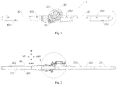
Fig. 1 is a schematic view of a spray arm assembly of a dishwasher according to an embodiment of the present disclosure. -
Fig. 2 is a sectional view of a spray arm assembly of a dishwasher according to an embodiment of the present disclosure. -
Fig. 3 is an enlarged view of part A ofFig. 2 . -
Fig. 4 is a schematic view illustrating that an auxiliary spray arm and a moving gear of a spray arm assembly of a dishwasher according to an embodiment of the present disclosure are disconnected. -
Fig. 5 is a schematic view of a main spray arm of a spray arm assembly of a dishwasher according to an embodiment of the present disclosure. -
Fig. 6 is a schematic view of a dishwasher according to an embodiment of the present disclosure. -
-
dishwasher 100, spray arm assembly 1,water pump 2,water cup 3,internal water conduit 4, -
upper dish rack 5,lower dish rack 6, -
fixed gear 10,water inlet 101, -
main spray arm 20,first spray lumen 201,first spray aperture 202,thrust aperture 203,snap 21,anti-leakage rib 22, mountingcircumferential wall 23, - moving
gear 30,gear portion 31,first connection portion 32,snap rib 321,second connection portion 33, -
auxiliary spray arm 40,second spray lumen 401,second spray aperture 402, -
locking piece 50, -
anti-wear gasket 60. - Reference will be made in detail to embodiments of the present disclosure. The embodiments described herein with reference to drawings are explanatory, illustrative, and used to generally understand the present disclosure. The embodiments shall not be construed to limit the present disclosure. The same or similar elements and the elements having same or similar functions are denoted by like reference numerals throughout the descriptions.
- With reference to drawings, a spray arm assembly 1 of a dishwasher according to embodiments of the present disclosure will be described in detail.
- As illustrated in
Fig. 1 to Fig. 5 , the spray arm assembly 1 according to the embodiments of the present disclosure includes afixed gear 10, amain spray arm 20, a movinggear 30 and anauxiliary spray arm 40. - The
fixed gear 10 defines awater inlet 101 in communication with a water feeder. Themain spray arm 20 is connected to thefixed gear 10 and pivotable about a central axis of thefixed gear 10. Themain spray arm 20 defines afirst spray lumen 201 in communication with thewater inlet 101. An outer surface of themain spray arm 20 defines athrust aperture 203 and a plurality offirst spray apertures 202 both in communication with thefirst spray lumen 201. - The moving
gear 30 is connected to themain spray arm 20, and under a reaction force of the water which is sprayed out through thethrust aperture 203, the movinggear 30 can rotate synchronously along with themain spray arm 20, that is, the moving gear can pivot about the central axis of thefixed gear 10. During pivoting of the moving gear, themoving gear 30 is engaged with thefixed gear 10 for transmission, such that themoving gear 30 can pivot on its own central axis. Theauxiliary spray arm 40 is connected to the movinggear 30 and synchronously moves along with the movinggear 30. Theauxiliary spray arm 40 internally defines asecond spray lumen 401 in communication with thewater inlet 101, and an outer circumferential surface of theauxiliary spray arm 40 defines a plurality ofsecond spray apertures 402 in communication with thesecond spray lumen 401. - For the spray arm assembly 1 according to the embodiments of the present disclosure, the
moving gear 30 is provided, engaged with thefixed gear 10 and connected to theauxiliary spray arm 40, such that theauxiliary spray arm 40 can pivot about a central axis of themain spray arm 20 and about the central axis of thefixed gear 10, that is, theauxiliary spray arm 40 can implement two-dimensional rotation. The plurality ofsecond spray apertures 402 of theauxiliary spray arm 40 can changes their locations continuously along with theauxiliary spray arm 40, thus changing angles of spraying water continuously, avoiding dead cleaning areas, shortening the cleaning time and improving the cleaning rate. Meanwhile, the spray arm assembly is comprised of themain spray arm 20, theauxiliary spray arm 40, the movinggear 30 and other separate components, such that not only the assembling is convenient, but also manufacturing difficulty can be effectively reduced, thereby facilitating maintenance and replacement, and lowering the cost. - Specifically, as illustrated in
Fig. 1 and Fig. 2 , the spray arm assembly 1 includes thefixed gear 10, themoving gear 30, themain spray arm 20 and theauxiliary spray arm 40. Thefixed gear 10 is fixed and configured to connect and support, such that the spray arm assembly 1 is connected to other components. Theauxiliary spray arm 40 is connected to themain spray arm 20 via themoving gear 30, and themain spray arm 20 can drive themoving gear 30 and theauxiliary spray arm 40 to rotate. - The moving
gear 30 is engaged with the fixedgear 10, the fixedgear 10 has teeth in a circle distributed horizontally, the movinggear 30 has teeth in a circle distributed vertically, and when the movinggear 30 moves under engagement with the fixedgear 10, the movinggear 30 can rotate and revolve, that is the movinggear 30 revolves about the fixedgear 10 while rotating on its own axis. Specifically, rotation of the movinggear 30 means that the movinggear 30 pivots about the central axis of the fixedgear 10, as indicated by a left arrow inFig. 1 ; revolution of the movinggear 30 means that the movinggear 30 pivots on its own central axis, as indicated by a right arrow inFig. 1 . - When the spray arm assembly 1 operates, water can be sprayed out through the
thrust aperture 203 of themain spray arm 20, themain spray arm 20 can rotate about the central axis of the fixedgear 10 in a horizontal plane under the thrust of reaction force, meanwhile, the movinggear 30 is driven by themain spray arm 20 to rotate synchronously along with themain spray arm 20, and theauxiliary spray arm 40 is driven by the movinggear 30 to rotate synchronously with themain spray arm 20. The spray arm assembly comprised of themain spray arm 20, theauxiliary spray arm 40 and the movinggear 30 can rotate in the horizontal plane. - When the moving
gear 30 is driven by themain spray arm 20 to move, the movement of the movinggear 30 is limited by the engagement between the movinggear 30 and the fixedgear 10, that is, the movinggear 30 pivots on its own central axis while rotating about the central axis of the fixedgear 10. Thus, theauxiliary spray arm 40 is driven by the movinggear 30 to pivot about the central axis of the movinggear 30. In such a case, the spray arm can rotate in the horizontal plane, and a portion of the spray arm can rotate in a vertical plane. The spray arm can implement two-dimensional rotation, increasing the cleaning rate. - It should be noted that, the moving
gear 30 is connected to themain spray arm 20, and theauxiliary spray arm 40 is connected to the movinggear 30. The spray arm assembly is not an integral component (that is the spray arm assembly is not formed integrally), but assembled by a plurality of separate components. Themain spray arm 20 is a separate component, the whole auxiliary spray arm is divided into two separate components, i.e. theauxiliary spray arm 40 and the movinggear 30. - As to a component with a simple structure and small scale, an integrally formed structure is generally superior to a split structure. However, a spray arm is generally shaped into a long strip and has a long extension size, and if the spray arm is an integral component, a mold needed during the manufacturing is large, the manufacturing difficulty is increased, defects easily occur to components, transportation is difficult and the cost is high.
- When the spray arm is designed as a structure with a plurality of separate components, obviously, sizes of the plurality of separate components are smaller than the size of the whole spray arm, and particularly, the length is reduced remarkably. A size of the needed mold can be reduced accordingly, the manufacturing difficulty is reduced, manufacturing quality is improved, the transportation is convenient and the assembling is simple. Further, when a separate component is damaged, it is only necessary to replace the damaged one rather than the whole spray arm, which reduces the cost greatly. Meanwhile, it is possible to select different
auxiliary spray arms 40 to cooperate with themain spray arm 20 according to needs, replacement cost of the spray arm assembly 1 is reduced, and the structure of the spray arm assembly 1 can be diversified, to satisfy more cleaning requirements and environmental conditions. - It should be noted herein that the division of the whole auxiliary spray arm into two separate components does not mean simple structural division or quantity division. The whole auxiliary spray arm is divided into two separate components, i.e. the
auxiliary spray arm 40 and the movinggear 30, such that the whole auxiliary spray arm can be divided into a plurality of structural components with different functions, theauxiliary arm 40 is configured as a component for spraying water, and the moving gear is configured as a component for connecting themain spray arm 20 and theauxiliary spray arm 40 and converting movement from revolution to simultaneous revolution and rotation. - If a spraying demand changes, different
auxiliary spray arms 40 can be replaced. If a demand for movement of theauxiliary spray arm 40 changes, the moving gear can be replaced accordingly. For example, another gear having a different number of teeth can be replaced, to allow theauxiliary spray arm 40 to have another rotation speed. - During operation, connections between components are easy to damage, particularly a connection configured for transmission. Regarding to the above structures, the moving
gear 30 is connected to three components at the same time, i.e. the fixedgear 10, themain spray arm 20 and theauxiliary spray arm 40. The movinggear 30 is relatively susceptible to damage, so the movinggear 30 is independently manufactured as a separate component for convenient replacement, and the manufacturing is relatively easier. - In short, for the spray arm assembly 1 according to the embodiments of the present disclosure, the spray arm can achieve conversion from one-dimensional rotation to two-dimensional rotation, thus improving the cleaning rate. The spray arm is no longer an integrally formed member, and the
auxiliary spray arm 40 can be comprised of two separate components, thus improving the manufacturability and reducing the cost. - It should be understood that, the moving
gear 30 can be connected to theauxiliary spray arm 40 in various manners. For example,Fig. 1 to Fig. 3 illustrate that the movinggear 30 can be connected to theauxiliary spray arm 40 by means of threads. Specifically, the movinggear 30 is provided with an internal thread, and theauxiliary spray arm 40 is provided with an external thread fitting with the internal thread. Of course, the movinggear 30 can also be provided with the internal thread, and the fixedgear 10 can also be provided with the external thread. For another example, in some other examples of the present disclosure, a snapping connection is provided between the movinggear 30 and theauxiliary spray arm 40. - As illustrated in
Fig. 3 , in some examples of the present disclosure, the movinggear 30 includes agear portion 31, afirst connection portion 32 and asecond connection portion 33. Thefirst connection portion 32 is connected to thegear portion 31, and thesecond connection portion 33 is connected to thefirst connection portion 32. In other words, thefirst connection portion 32 is connected between thegear portion 31 and thesecond connection portion 33. As illustrated inFig. 1 to Fig. 3 , thegear portion 31 is engaged with the fixedgear 10. Thefirst connection portion 32 is fitted over themain spray arm 20 and pivotably connected to themain spray arm 20. Thesecond connection portion 33 is connected to theauxiliary spray arm 40, specifically by means of threaded connection, snapping connection and the like. - Therefore, the
gear portion 31 can function to be engaged with the fixedgear 10, thefirst connection portion 32 can function to be connected to themain spray arm 20, and thesecond connection portion 33 can function to be connected to theauxiliary spray arm 40, such that all the components have definite division of work and can be individually manufactured according to respective needs. - The
second connection portion 33 can be connected to themain spray arm 20 through snapping. Specifically, asnap rib 321 is provided to an inner circumferential surface of thefirst connection portion 32. Asnap 21 is provided to an outer circumferential surface of themain spray arm 20. When themain spray arm 20 is connected to the movinggear 30, thesnap rib 321 and thesnap 21 are interlocked, thus facilitating the assembling and firming the connection. - As illustrated in
Fig. 4 , a circle of thesnap ribs 321 can be provided to the inner circumferential surface of thefirst connection portion 32, and configured as convex ribs extending to a central axis of the first connection portion in a radial direction of thefirst connection portion 32. As illustrated inFig. 5 , a circle of thesnaps 21 can be provided to the outer circumferential surface of themain spray arm 20, and configured as protrusions extending away from the central axis of themain spray arm 20 in a radial direction of themain spray arm 20. Advantageously, as illustrated inFig. 3 , mating surfaces where the protrusion and the convex rib abut against with each other are configured as bevels, thus ensuring the snapping connection while reducing difficulties during assembling. - As illustrated in
Fig. 2 , themain spray arm 20 has an end extending beyond connection between the movinggear 30 and theauxiliary spray arm 40. Accordingly, themain spray arm 20 can reinforce the rigid of the spray arm assembly 1 at the connection between the movinggear 30 and theauxiliary spray arm 40, thus reinforcing the connection strength of the spray arm assembly 1, and hence the spray arm assembly 1 is hard to disassemble. - If gaps occur in the connection between the
main spray arm 20 and the movinggear 30 and in the connection between the auxiliary spray arm 40and the movinggear 30, water in thesecond spray lumen 401 easily flows out through the gaps, which causes unnecessary water leakage from the spray arm assembly 1 and weakens water spraying, thus degrading the cleaning effect. In order to reduce the water leakage from spray arm 1, ananti-leakage rib 22 is provided to an outer circumferential surface of the end of themain spray arm 20, and theanti-leakage rib 22 can extend from the outer circumferential surface of themain spray arm 20 to an inner circumferential surface of theauxiliary spray arm 40, to prevent water in thesecond spray lumen 401 from flowing to the gaps in the connections. - Meanwhile, considering that the moving
gear 30 and theauxiliary spray arm 40 are capable of rotating relative to themain spray arm 20, theanti-leakage rib 22 should not abut against the inner circumferential surface of theauxiliary spray arm 40 for smooth rotation of the spray arm and the movinggear 30. Preferably, a clearance fit is provided between theanti-leakage rib 22 and the inner circumferential surface of theauxiliary spray arm 40, such that smooth rotation of theauxiliary spray arm 40 and the movinggear 30 are ensured while water leakage is avoided. - As illustrated in
Fig. 2 , theanti-leakage rib 22 and thesnap rib 321 each are concentric with theauxiliary spray arm 40 and the movinggear 30, and small clearance fits are provided between theanti-leakage rib 22 and theauxiliary spray arm 40, and between thesnap rib 321 and the movinggear 30, such that theauxiliary spray arm 40 can be kept horizontal, and rotational resistance is small. Moreover, two layers ofanti-leakage ribs 22 can better prevent water leakage. - A plurality of
anti-leakage ribs 22 can be provided, and the plurality ofanti-leakage ribs 22 can be spaced apart along an axial direction of themain spray arm 20. For example, as illustrated inFig. 2 andFig. 5 , twoanti-leakage ribs 22 can be provided. The twoanti-leakage ribs 22 can construct two-layer protection to prevent water leakage better, and at the same time, theauxiliary spray arm 40 can smoothly rotate under low rotation resistance. - According to some embodiments of the present disclosure, the fixed
gear 10 is connected to themain spray arm 20 via alocking piece 50. In other words, the lockingpiece 50 is configured to mount themain spray arm 20 to the fixedgear 10. Specifically, themain spray arm 20 has a mountingcircumferential wall 23 protruding outwards, and the fixedgear 10 is fitted over the mountingcircumferential wall 23 with a gap therebetween, to ensure that the movinggear 30 can pivot relative to the fixedgear 10. The mountingcircumferential wall 23 is configured as a hollow cylinder with two open ends, one end is connected to thefirst spray lumen 201, and the other end is in communication with the water feeder. - The locking
piece 50 is connected to the mountingcircumferential wall 23, and when themain spray arm 20 pivots, the mountingcircumferential wall 23 rotates to drive the lockingpiece 50 to pivot relative to the fixedgear 10. Part of the lockingpiece 50 abuts against the fixedgear 10 to prevent the fixedgear 10 from moving up and then falling off from an upper end of the mountingcircumferential wall 23. Preferably, ananti-wear gasket 60 can be arranged between the lockingpiece 50 and the fixedgear 10. Theanti-wear gasket 60 can reduce friction between the lockingpiece 50 and the fixedgear 10. - To sum up, with the spray arm assembly 1 according to embodiments of the present disclosure, water is sprayed out through the
thrust aperture 203 of themain spray arm 20, the reaction force pushes themain spray arm 20 to rotate in the horizontal plane and provides a power for the second-dimension rotation of the movinggear 30, such that the spray arm can implement two-dimensional rotation, thus improving the cleaning rate. The whole spray arm is divided into a plurality of separate components, and particularly, the whole auxiliary spray arm is designed to have theauxiliary spray arm 40 and the movinggear 30, achieving high manufacturability. Further, theanti-leakage rib 22 can prevent water leakage better. - As illustrated in
Fig. 6 , adishwasher 100 according to embodiments of the present disclosure includes awater pump 2, awater cup 3, aninternal water conduit 4, anupper dish rack 5, alower dish rack 6 and a spray arm assembly 11 according to the above embodiments. The water cup storeswater 3 is stored with water, the spray arm assembly 11 is connected to thewater cup 3 by theinternal water conduit 4, and thewater pump 2 is connected between thewater cup 3 and theinternal water conduit 4 to make the water in thewater cup 3 flow into theinternal water conduit 4 continuously. Theinternal water conduit 4 has a water outlet connected to thewater inlet 101 of the spray arm assembly 11. Water can be sprayed out through thefirst spray aperture 202 and thesecond spray aperture 402 to theupper dish rack 5 and thelower dish rack 6, to wash dishes in theupper dish rack 5 and thelower dish rack 6. - Because the spray arm assembly 11 according to the embodiments of the present disclosure has the above technical effects, the
dishwasher 100 according to the embodiments of the present disclosure has the high manufacturability and high cleaning rate. - Other configurations and operations of the
dishwasher 100 according to the embodiments of the present disclosure are known to those skilled in the art and are not described in detail herein. - In the specification, it is to be understood that terms such as "length," "upper," "lower," "front," "rear," "left," "right," "vertical," "horizontal," "top," "bottom," "inner," "outer," "clockwise," "counterclockwise," "axial," "radial," and "circumferential" should be construed to refer to the orientation as then described or as shown in the drawings under discussion. These relative terms are for convenience of description and do not require that the present invention be constructed or operated in a particular orientation.
- In addition, terms such as "first" and "second" are used herein for purposes of description and are not intended to indicate or imply relative importance or significance or to imply the number of indicated technical features. Thus, the feature defined with "first" and "second" may comprise one or more of this feature. In the description of the present invention, the term "a plurality of' means two or more than two, unless specified otherwise.
- Reference throughout this specification to "an embodiment," "some embodiments," "a example," means that a particular feature, structure, material, or characteristic described in connection with the embodiment or example is included in at least one embodiment or example of the present disclosure. Thus, the appearances of the phrases in various places throughout this specification are not necessarily referring to the same embodiment or example of the present disclosure. Furthermore, the particular features, structures, materials, or characteristics may be combined in any suitable manner in one or more embodiments or examples. Those skilled in the art can combine or composite features in different embodiments or examples described in the specification without contradiction.
- Although explanatory embodiments have been shown and described, it would be appreciated by those skilled in the art that the above embodiments cannot be construed to limit the present disclosure, and changes, alternatives, and modifications can be made in the embodiments without departing from the principles and scope of the present disclosure.
Claims (9)
- A spray arm assembly (1) of a dishwasher (100), comprising:a fixed gear (10), defining a water inlet (101) in communication with a water feeder;a main spray arm (20), connected to the fixed gear (10) and pivotable about a central axis of the fixed gear (10), defining a first spray lumen (201) in communication with the water inlet (101), and having an outer surface defining a thrust aperture (203) and a plurality of first spray apertures (202) both in communication with the first spray lumen (201);a moving gear (30), connected to the main spray arm (20), engaged with the fixed gear (10), and pivotable on its own central axis and about the central axis of the fixed gear (10); andan auxiliary spray arm (40), detachably connected to the moving gear (30) and synchronously moving along with the moving gear (30), defining a second spray lumen (401) in communication with the water inlet (101), and having an outer circumferential surface defining a plurality of second spray apertures (402) in communication with the second spray lumen (401);the spray arm assembly (1) being characterised in that the moving gear (30) is connected to the auxiliary spray arm (40) by means of threaded connection or snapping connection.
- The spray arm assembly (1) according to claim 1, wherein the moving gear (30) comprises:a gear portion, engaged with the fixed gear (10);a first connection portion, connected to the gear portion, fitted over the main spray arm (20) and pivotably connected to the main spray arm (20); anda second connection portion, connected to the first connection portion, and connected to the auxiliary spray arm by means of threaded connection or snapping connection.
- The spray arm assembly (1) according to claim 2, wherein the main spray arm (20) has an outer circumferential surface provided with a snap, and the first connection portion has an inner circumferential surface provided with a snap rib fitted with the snap.
- The spray arm assembly (1) according to any one of claims 1 to 3, wherein the main spray arm (20) has an end extending beyond connection between the moving gear and the auxiliary spray arm (40), the end of the main spray arm (20) has an outer circumferential surface provided with an anti-leakage rib (22), and a clearance fit is provided between the anti-leakage rib (22) and an inner circumferential surface of the auxiliary spray arm (40).
- The spray arm assembly (1) according to claim 4, wherein a plurality of anti-leakage ribs are provided, and the plurality of anti-leakage ribs are spaced apart along an axial direction of the main spray arm (20).
- The spray arm assembly (1) according to any one of claims 1 to 5, wherein the fixed gear (10) is connected to the main spray arm (20) via a locking piece.
- The spray arm assembly (1) according to claim 6, wherein the main spray arm (20) has a mounting circumferential wall protruding outwards, the fixed gear (10) is fitted over the mounting circumferential wall with a gap therebetween, a pressing piece is connected to the mounting circumferential wall, and part of the pressing piece abuts against the fixed gear (10) to prevent the fixed gear (10) from falling off from the mounting circumferential wall.
- The spray arm assembly (1) according to claim 7, wherein an anti-wear gasket is arranged between the part of the locking piece and the fixed gear (10).
- A dishwasher (100), comprising a spray arm assembly (1) according to any one of claims 1 to 8.
Applications Claiming Priority (3)
| Application Number | Priority Date | Filing Date | Title |
|---|---|---|---|
| CN201520223932.2U CN204744061U (en) | 2015-04-14 | 2015-04-14 | Spray arm subassembly of dish washer and dish washer thereof |
| CN201510176011.XA CN104739346B (en) | 2015-04-14 | 2015-04-14 | The spray arm component and its dish-washing machine of dish-washing machine |
| PCT/CN2015/096346 WO2016165348A1 (en) | 2015-04-14 | 2015-12-03 | Spraying arm assembly of dish washer and dish washer having same |
Publications (3)
| Publication Number | Publication Date |
|---|---|
| EP3284385A1 EP3284385A1 (en) | 2018-02-21 |
| EP3284385A4 EP3284385A4 (en) | 2018-05-02 |
| EP3284385B1 true EP3284385B1 (en) | 2019-11-27 |
Family
ID=57127165
Family Applications (1)
| Application Number | Title | Priority Date | Filing Date |
|---|---|---|---|
| EP15889044.2A Active EP3284385B1 (en) | 2015-04-14 | 2015-12-03 | Spraying arm assembly of dish washer and dish washer having same |
Country Status (3)
| Country | Link |
|---|---|
| US (1) | US10638909B2 (en) |
| EP (1) | EP3284385B1 (en) |
| WO (1) | WO2016165348A1 (en) |
Families Citing this family (9)
| Publication number | Priority date | Publication date | Assignee | Title |
|---|---|---|---|---|
| WO2016169303A1 (en) * | 2015-04-22 | 2016-10-27 | 佛山市顺德区美的洗涤电器制造有限公司 | Spraying arm assembly for dishwasher and dishwasher having same |
| CN108523809A (en) * | 2018-04-16 | 2018-09-14 | 佛山市顺德区美的洗涤电器制造有限公司 | Spraying arm of dish washer and dish-washing machine |
| CN109730606B (en) * | 2019-03-13 | 2024-07-12 | 佛山市顺德区美的洗涤电器制造有限公司 | Spray arm assembly of dish washer and dish washer that has it |
| CN110448254B (en) * | 2019-08-30 | 2024-02-13 | 小熊电器股份有限公司 | Dishwasher spray arm assembly |
| CN110710942B (en) * | 2019-10-30 | 2025-04-29 | 浙江蓝炬星电器有限公司 | A spray arm of a dishwasher and a manufacturing method thereof |
| EP4023135A1 (en) * | 2020-12-30 | 2022-07-06 | Midea Group Co., Ltd. | Spray system for a dishwasher |
| CN116982896B (en) * | 2022-04-26 | 2026-03-10 | 宁波方太厨具有限公司 | Cleaning machine |
| CN115444341B (en) * | 2022-09-30 | 2025-01-28 | 宁波方太厨具有限公司 | Spray arm for cleaning machine and cleaning machine |
| CN116530907A (en) * | 2023-06-12 | 2023-08-04 | 广东慧曼智能科技有限公司 | Telescopic spray arm structure of dish washer |
Family Cites Families (8)
| Publication number | Priority date | Publication date | Assignee | Title |
|---|---|---|---|---|
| EP1882435A1 (en) | 2006-07-24 | 2008-01-30 | Electrolux Home Products Corporation N.V. | Revolving sprinkling assembly |
| US8347898B2 (en) | 2009-04-30 | 2013-01-08 | Whirlpool Corporation | Dishwasher with rotating zone wash sprayers |
| US8578954B2 (en) * | 2009-12-21 | 2013-11-12 | Whirlpool Corporation | Spray arm assembly for a dishwasher |
| KR101821201B1 (en) * | 2011-06-02 | 2018-01-23 | 엘지전자 주식회사 | DISHWAHSER and CONTROL METHOD THEREOF |
| CN203987928U (en) * | 2014-07-16 | 2014-12-10 | 佛山市顺德区美的洗涤电器制造有限公司 | Spray arm device and dish-washing machine |
| CN204158346U (en) * | 2014-10-22 | 2015-02-18 | 佛山市顺德区美的洗涤电器制造有限公司 | Spray arm device and dish-washing machine |
| CN204744061U (en) * | 2015-04-14 | 2015-11-11 | 芜湖美的洗涤电器制造有限公司 | Spray arm subassembly of dish washer and dish washer thereof |
| CN104739346B (en) * | 2015-04-14 | 2017-09-29 | 佛山市顺德区美的洗涤电器制造有限公司 | The spray arm component and its dish-washing machine of dish-washing machine |
-
2015
- 2015-12-03 US US15/566,722 patent/US10638909B2/en active Active
- 2015-12-03 EP EP15889044.2A patent/EP3284385B1/en active Active
- 2015-12-03 WO PCT/CN2015/096346 patent/WO2016165348A1/en not_active Ceased
Non-Patent Citations (1)
| Title |
|---|
| None * |
Also Published As
| Publication number | Publication date |
|---|---|
| EP3284385A4 (en) | 2018-05-02 |
| WO2016165348A1 (en) | 2016-10-20 |
| EP3284385A1 (en) | 2018-02-21 |
| US10638909B2 (en) | 2020-05-05 |
| US20180103825A1 (en) | 2018-04-19 |
Similar Documents
| Publication | Publication Date | Title |
|---|---|---|
| US10638909B2 (en) | Spray arm assembly of dish washer and dish washer having same | |
| CN104739346B (en) | The spray arm component and its dish-washing machine of dish-washing machine | |
| EP3287062B1 (en) | Spraying arm assembly for dishwasher and dishwasher having same | |
| CN204744061U (en) | Spray arm subassembly of dish washer and dish washer thereof | |
| EP3384821B1 (en) | Spraying arm assembly of dish washer and dish washer having same | |
| WO2018113389A1 (en) | Dishwasher spray arm connection structure and dishwasher | |
| CN107028572B (en) | Spray arm device for dishwasher and dishwasher having same | |
| CN106137075B (en) | Dishwasher top spray assembly and dishwasher | |
| US10349811B2 (en) | Dishwasher | |
| CN205338873U (en) | Spray arm subassembly and have its dish washer | |
| CN106594838B (en) | Self-cleaning device for hood oil screen and oil screen assembly and range hood having the same | |
| CN109875476A (en) | Spray arm assembly and dish washing machine with same | |
| CN209899306U (en) | Spray system installed on cleaning machine and cleaning machine with spray system | |
| CN221555493U (en) | Spray arm assembly and dishwasher | |
| CN216876287U (en) | Double-layer spray arm assembly and dish washing machine with same | |
| CN216933101U (en) | Dish washing machine and spraying device | |
| EP3843604B1 (en) | A dishwasher having improved washing performance | |
| CN218606509U (en) | Spray arm assembly and dish washing machine | |
| CN208808411U (en) | A new type of dishwasher lower spray arm | |
| CN207734135U (en) | The top spray water-bound of dish-washing machine | |
| CN110856641B (en) | A water intake mechanism for a sprayer and a dishwasher | |
| CN223365500U (en) | Middle spraying device and cleaning machine | |
| CN205268091U (en) | Spray arm subassembly and have its dish washer | |
| CN210383843U (en) | Spraying system and cleaning machine using same | |
| CN204950857U (en) | Spray arm subassembly |
Legal Events
| Date | Code | Title | Description |
|---|---|---|---|
| STAA | Information on the status of an ep patent application or granted ep patent |
Free format text: STATUS: THE INTERNATIONAL PUBLICATION HAS BEEN MADE |
|
| PUAI | Public reference made under article 153(3) epc to a published international application that has entered the european phase |
Free format text: ORIGINAL CODE: 0009012 |
|
| STAA | Information on the status of an ep patent application or granted ep patent |
Free format text: STATUS: REQUEST FOR EXAMINATION WAS MADE |
|
| 17P | Request for examination filed |
Effective date: 20171011 |
|
| AK | Designated contracting states |
Kind code of ref document: A1 Designated state(s): AL AT BE BG CH CY CZ DE DK EE ES FI FR GB GR HR HU IE IS IT LI LT LU LV MC MK MT NL NO PL PT RO RS SE SI SK SM TR |
|
| AX | Request for extension of the european patent |
Extension state: BA ME |
|
| RIC1 | Information provided on ipc code assigned before grant |
Ipc: A47L 15/23 20060101AFI20180319BHEP Ipc: A47L 15/22 20060101ALI20180319BHEP Ipc: A47L 15/42 20060101ALI20180319BHEP |
|
| A4 | Supplementary search report drawn up and despatched |
Effective date: 20180405 |
|
| DAV | Request for validation of the european patent (deleted) | ||
| DAX | Request for extension of the european patent (deleted) | ||
| GRAP | Despatch of communication of intention to grant a patent |
Free format text: ORIGINAL CODE: EPIDOSNIGR1 |
|
| STAA | Information on the status of an ep patent application or granted ep patent |
Free format text: STATUS: GRANT OF PATENT IS INTENDED |
|
| INTG | Intention to grant announced |
Effective date: 20190702 |
|
| GRAS | Grant fee paid |
Free format text: ORIGINAL CODE: EPIDOSNIGR3 |
|
| GRAA | (expected) grant |
Free format text: ORIGINAL CODE: 0009210 |
|
| STAA | Information on the status of an ep patent application or granted ep patent |
Free format text: STATUS: THE PATENT HAS BEEN GRANTED |
|
| AK | Designated contracting states |
Kind code of ref document: B1 Designated state(s): AL AT BE BG CH CY CZ DE DK EE ES FI FR GB GR HR HU IE IS IT LI LT LU LV MC MK MT NL NO PL PT RO RS SE SI SK SM TR |
|
| REG | Reference to a national code |
Ref country code: GB Ref legal event code: FG4D |
|
| REG | Reference to a national code |
Ref country code: CH Ref legal event code: EP |
|
| REG | Reference to a national code |
Ref country code: AT Ref legal event code: REF Ref document number: 1205785 Country of ref document: AT Kind code of ref document: T Effective date: 20191215 |
|
| REG | Reference to a national code |
Ref country code: DE Ref legal event code: R096 Ref document number: 602015042752 Country of ref document: DE |
|
| REG | Reference to a national code |
Ref country code: IE Ref legal event code: FG4D |
|
| REG | Reference to a national code |
Ref country code: NL Ref legal event code: MP Effective date: 20191127 |
|
| REG | Reference to a national code |
Ref country code: LT Ref legal event code: MG4D |
|
| PG25 | Lapsed in a contracting state [announced via postgrant information from national office to epo] |
Ref country code: BG Free format text: LAPSE BECAUSE OF FAILURE TO SUBMIT A TRANSLATION OF THE DESCRIPTION OR TO PAY THE FEE WITHIN THE PRESCRIBED TIME-LIMIT Effective date: 20200227 Ref country code: FI Free format text: LAPSE BECAUSE OF FAILURE TO SUBMIT A TRANSLATION OF THE DESCRIPTION OR TO PAY THE FEE WITHIN THE PRESCRIBED TIME-LIMIT Effective date: 20191127 Ref country code: SE Free format text: LAPSE BECAUSE OF FAILURE TO SUBMIT A TRANSLATION OF THE DESCRIPTION OR TO PAY THE FEE WITHIN THE PRESCRIBED TIME-LIMIT Effective date: 20191127 Ref country code: LV Free format text: LAPSE BECAUSE OF FAILURE TO SUBMIT A TRANSLATION OF THE DESCRIPTION OR TO PAY THE FEE WITHIN THE PRESCRIBED TIME-LIMIT Effective date: 20191127 Ref country code: NL Free format text: LAPSE BECAUSE OF FAILURE TO SUBMIT A TRANSLATION OF THE DESCRIPTION OR TO PAY THE FEE WITHIN THE PRESCRIBED TIME-LIMIT Effective date: 20191127 Ref country code: GR Free format text: LAPSE BECAUSE OF FAILURE TO SUBMIT A TRANSLATION OF THE DESCRIPTION OR TO PAY THE FEE WITHIN THE PRESCRIBED TIME-LIMIT Effective date: 20200228 Ref country code: NO Free format text: LAPSE BECAUSE OF FAILURE TO SUBMIT A TRANSLATION OF THE DESCRIPTION OR TO PAY THE FEE WITHIN THE PRESCRIBED TIME-LIMIT Effective date: 20200227 Ref country code: LT Free format text: LAPSE BECAUSE OF FAILURE TO SUBMIT A TRANSLATION OF THE DESCRIPTION OR TO PAY THE FEE WITHIN THE PRESCRIBED TIME-LIMIT Effective date: 20191127 |
|
| PG25 | Lapsed in a contracting state [announced via postgrant information from national office to epo] |
Ref country code: IS Free format text: LAPSE BECAUSE OF FAILURE TO SUBMIT A TRANSLATION OF THE DESCRIPTION OR TO PAY THE FEE WITHIN THE PRESCRIBED TIME-LIMIT Effective date: 20200327 Ref country code: HR Free format text: LAPSE BECAUSE OF FAILURE TO SUBMIT A TRANSLATION OF THE DESCRIPTION OR TO PAY THE FEE WITHIN THE PRESCRIBED TIME-LIMIT Effective date: 20191127 Ref country code: RS Free format text: LAPSE BECAUSE OF FAILURE TO SUBMIT A TRANSLATION OF THE DESCRIPTION OR TO PAY THE FEE WITHIN THE PRESCRIBED TIME-LIMIT Effective date: 20191127 |
|
| PG25 | Lapsed in a contracting state [announced via postgrant information from national office to epo] |
Ref country code: AL Free format text: LAPSE BECAUSE OF FAILURE TO SUBMIT A TRANSLATION OF THE DESCRIPTION OR TO PAY THE FEE WITHIN THE PRESCRIBED TIME-LIMIT Effective date: 20191127 |
|
| PG25 | Lapsed in a contracting state [announced via postgrant information from national office to epo] |
Ref country code: DK Free format text: LAPSE BECAUSE OF FAILURE TO SUBMIT A TRANSLATION OF THE DESCRIPTION OR TO PAY THE FEE WITHIN THE PRESCRIBED TIME-LIMIT Effective date: 20191127 Ref country code: EE Free format text: LAPSE BECAUSE OF FAILURE TO SUBMIT A TRANSLATION OF THE DESCRIPTION OR TO PAY THE FEE WITHIN THE PRESCRIBED TIME-LIMIT Effective date: 20191127 Ref country code: PT Free format text: LAPSE BECAUSE OF FAILURE TO SUBMIT A TRANSLATION OF THE DESCRIPTION OR TO PAY THE FEE WITHIN THE PRESCRIBED TIME-LIMIT Effective date: 20200419 Ref country code: ES Free format text: LAPSE BECAUSE OF FAILURE TO SUBMIT A TRANSLATION OF THE DESCRIPTION OR TO PAY THE FEE WITHIN THE PRESCRIBED TIME-LIMIT Effective date: 20191127 Ref country code: RO Free format text: LAPSE BECAUSE OF FAILURE TO SUBMIT A TRANSLATION OF THE DESCRIPTION OR TO PAY THE FEE WITHIN THE PRESCRIBED TIME-LIMIT Effective date: 20191127 Ref country code: CZ Free format text: LAPSE BECAUSE OF FAILURE TO SUBMIT A TRANSLATION OF THE DESCRIPTION OR TO PAY THE FEE WITHIN THE PRESCRIBED TIME-LIMIT Effective date: 20191127 |
|
| REG | Reference to a national code |
Ref country code: CH Ref legal event code: PL |
|
| REG | Reference to a national code |
Ref country code: BE Ref legal event code: MM Effective date: 20191231 |
|
| REG | Reference to a national code |
Ref country code: DE Ref legal event code: R097 Ref document number: 602015042752 Country of ref document: DE |
|
| PG25 | Lapsed in a contracting state [announced via postgrant information from national office to epo] |
Ref country code: MC Free format text: LAPSE BECAUSE OF FAILURE TO SUBMIT A TRANSLATION OF THE DESCRIPTION OR TO PAY THE FEE WITHIN THE PRESCRIBED TIME-LIMIT Effective date: 20191127 Ref country code: SK Free format text: LAPSE BECAUSE OF FAILURE TO SUBMIT A TRANSLATION OF THE DESCRIPTION OR TO PAY THE FEE WITHIN THE PRESCRIBED TIME-LIMIT Effective date: 20191127 Ref country code: SM Free format text: LAPSE BECAUSE OF FAILURE TO SUBMIT A TRANSLATION OF THE DESCRIPTION OR TO PAY THE FEE WITHIN THE PRESCRIBED TIME-LIMIT Effective date: 20191127 |
|
| REG | Reference to a national code |
Ref country code: AT Ref legal event code: MK05 Ref document number: 1205785 Country of ref document: AT Kind code of ref document: T Effective date: 20191127 |
|
| PLBE | No opposition filed within time limit |
Free format text: ORIGINAL CODE: 0009261 |
|
| STAA | Information on the status of an ep patent application or granted ep patent |
Free format text: STATUS: NO OPPOSITION FILED WITHIN TIME LIMIT |
|
| PG25 | Lapsed in a contracting state [announced via postgrant information from national office to epo] |
Ref country code: IE Free format text: LAPSE BECAUSE OF NON-PAYMENT OF DUE FEES Effective date: 20191203 Ref country code: LU Free format text: LAPSE BECAUSE OF NON-PAYMENT OF DUE FEES Effective date: 20191203 |
|
| 26N | No opposition filed |
Effective date: 20200828 |
|
| PG25 | Lapsed in a contracting state [announced via postgrant information from national office to epo] |
Ref country code: AT Free format text: LAPSE BECAUSE OF FAILURE TO SUBMIT A TRANSLATION OF THE DESCRIPTION OR TO PAY THE FEE WITHIN THE PRESCRIBED TIME-LIMIT Effective date: 20191127 Ref country code: LI Free format text: LAPSE BECAUSE OF NON-PAYMENT OF DUE FEES Effective date: 20191231 Ref country code: CH Free format text: LAPSE BECAUSE OF NON-PAYMENT OF DUE FEES Effective date: 20191231 Ref country code: SI Free format text: LAPSE BECAUSE OF FAILURE TO SUBMIT A TRANSLATION OF THE DESCRIPTION OR TO PAY THE FEE WITHIN THE PRESCRIBED TIME-LIMIT Effective date: 20191127 Ref country code: BE Free format text: LAPSE BECAUSE OF NON-PAYMENT OF DUE FEES Effective date: 20191231 Ref country code: PL Free format text: LAPSE BECAUSE OF FAILURE TO SUBMIT A TRANSLATION OF THE DESCRIPTION OR TO PAY THE FEE WITHIN THE PRESCRIBED TIME-LIMIT Effective date: 20191127 |
|
| PG25 | Lapsed in a contracting state [announced via postgrant information from national office to epo] |
Ref country code: IT Free format text: LAPSE BECAUSE OF FAILURE TO SUBMIT A TRANSLATION OF THE DESCRIPTION OR TO PAY THE FEE WITHIN THE PRESCRIBED TIME-LIMIT Effective date: 20191127 |
|
| PG25 | Lapsed in a contracting state [announced via postgrant information from national office to epo] |
Ref country code: CY Free format text: LAPSE BECAUSE OF FAILURE TO SUBMIT A TRANSLATION OF THE DESCRIPTION OR TO PAY THE FEE WITHIN THE PRESCRIBED TIME-LIMIT Effective date: 20191127 |
|
| PG25 | Lapsed in a contracting state [announced via postgrant information from national office to epo] |
Ref country code: HU Free format text: LAPSE BECAUSE OF FAILURE TO SUBMIT A TRANSLATION OF THE DESCRIPTION OR TO PAY THE FEE WITHIN THE PRESCRIBED TIME-LIMIT; INVALID AB INITIO Effective date: 20151203 Ref country code: MT Free format text: LAPSE BECAUSE OF FAILURE TO SUBMIT A TRANSLATION OF THE DESCRIPTION OR TO PAY THE FEE WITHIN THE PRESCRIBED TIME-LIMIT Effective date: 20191127 |
|
| PG25 | Lapsed in a contracting state [announced via postgrant information from national office to epo] |
Ref country code: TR Free format text: LAPSE BECAUSE OF FAILURE TO SUBMIT A TRANSLATION OF THE DESCRIPTION OR TO PAY THE FEE WITHIN THE PRESCRIBED TIME-LIMIT Effective date: 20191127 |
|
| PG25 | Lapsed in a contracting state [announced via postgrant information from national office to epo] |
Ref country code: MK Free format text: LAPSE BECAUSE OF FAILURE TO SUBMIT A TRANSLATION OF THE DESCRIPTION OR TO PAY THE FEE WITHIN THE PRESCRIBED TIME-LIMIT Effective date: 20191127 |
|
| P01 | Opt-out of the competence of the unified patent court (upc) registered |
Effective date: 20230526 |
|
| PGFP | Annual fee paid to national office [announced via postgrant information from national office to epo] |
Ref country code: DE Payment date: 20251212 Year of fee payment: 11 |
|
| PGFP | Annual fee paid to national office [announced via postgrant information from national office to epo] |
Ref country code: GB Payment date: 20251211 Year of fee payment: 11 |
|
| PGFP | Annual fee paid to national office [announced via postgrant information from national office to epo] |
Ref country code: FR Payment date: 20251212 Year of fee payment: 11 |