EP3283852B1 - Plate carrier guide for an orifice fitting - Google Patents
Plate carrier guide for an orifice fitting Download PDFInfo
- Publication number
- EP3283852B1 EP3283852B1 EP16780646.2A EP16780646A EP3283852B1 EP 3283852 B1 EP3283852 B1 EP 3283852B1 EP 16780646 A EP16780646 A EP 16780646A EP 3283852 B1 EP3283852 B1 EP 3283852B1
- Authority
- EP
- European Patent Office
- Prior art keywords
- flowmeter
- orifice
- insert
- disposed
- plate carrier
- Prior art date
- Legal status (The legal status is an assumption and is not a legal conclusion. Google has not performed a legal analysis and makes no representation as to the accuracy of the status listed.)
- Not-in-force
Links
Images






Classifications
-
- G—PHYSICS
- G01—MEASURING; TESTING
- G01F—MEASURING VOLUME, VOLUME FLOW, MASS FLOW OR LIQUID LEVEL; METERING BY VOLUME
- G01F15/00—Details of, or accessories for, apparatus of groups G01F1/00 - G01F13/00 insofar as such details or appliances are not adapted to particular types of such apparatus
-
- G—PHYSICS
- G01—MEASURING; TESTING
- G01F—MEASURING VOLUME, VOLUME FLOW, MASS FLOW OR LIQUID LEVEL; METERING BY VOLUME
- G01F1/00—Measuring the volume flow or mass flow of fluid or fluent solid material wherein the fluid passes through a meter in a continuous flow
- G01F1/05—Measuring the volume flow or mass flow of fluid or fluent solid material wherein the fluid passes through a meter in a continuous flow by using mechanical effects
- G01F1/34—Measuring the volume flow or mass flow of fluid or fluent solid material wherein the fluid passes through a meter in a continuous flow by using mechanical effects by measuring pressure or differential pressure
- G01F1/36—Measuring the volume flow or mass flow of fluid or fluent solid material wherein the fluid passes through a meter in a continuous flow by using mechanical effects by measuring pressure or differential pressure the pressure or differential pressure being created by the use of flow constriction
- G01F1/40—Details of construction of the flow constriction devices
- G01F1/42—Orifices or nozzles
Definitions
- flowmeters are used to measure the volumetric flow rate of a gaseous or liquid flow stream moving through a piping section.
- Flowmeters can include an orifice fitting, which orients and supports an orifice plate in a plate carrier that extends across the piping section perpendicular to the direction of the flow stream.
- a dual chamber orifice fitting allows the plate carrier be removed from the fitting without interrupting the flow stream moving through the piping section.
- US 1965826 describes orifice meter plate housings.
- US4531539 describes a control valve for flow or solids or fluids which controls flow and provides an opening for solids dumping.
- embodiments described herein include a combination of features and characteristics intended to address various shortcomings associated with certain prior devices, systems, and methods.
- the various features and characteristics described above, as well as others, will be readily apparent to those of ordinary skill in the art upon reading the following detailed description, and by referring to the accompanying drawings.
- the terms “including” and “comprising” are used in an open-ended fashion, and thus should be interpreted to mean “including, but not limited to ."
- the term “couple” or “couples” is intended to mean either an indirect or direct connection. Thus, if a first device couples to a second device, that connection may be through a direct connection, or through an indirect connection via other devices, components, and connections.
- the terms “axial” and “axially” generally mean along or parallel to a central axis (e.g., central axis of a body or a port), while the terms “radial” and “radially” generally mean perpendicular to the central axis. For instance, an axial distance refers to a distance measured along or parallel to the central axis, and a radial distance means a distance measured perpendicular to the central axis.
- Orifice flowmeter 12 includes body 16 and top 18.
- Body 16 encloses lower chamber 20, which is in fluid communication with the interior or bore of pipeline 34, which extends along a longitudinal axis 35 on either side of flowmeter 12.
- a flow passage 37 extends through and includes the interior of the pipeline 34 and lower chamber 20.
- Top 18 encloses upper chamber 22, which houses a plate carrier guide or insert 100, and is connected to body 16 by bolts 17.
- Insert 100 is an example of a positioning device.
- Aperture 30 defines an opening connecting upper chamber 22 to lower chamber 20.
- Aperture 30 is configured to isolate upper chamber 22 and the insert 100 from lower chamber 20 and from flow passage when in a closed configuration, and aperture 30 is configured to allow communication among these features when in an open configuration.
- Valve seat 24 is connected to top 18 and provides a sealing engagement with a slide valve plate 56, which is slidably actuated by rotating gear shaft 54.
- Lower drive 36 and upper drive 38 operate to move orifice plate carrier 32 vertically within flowmeter 12.
- Orifice 31 is located on an orifice plate 33 supported by orifice plate carrier 32.
- Orifice plate carrier 32 is shown in a metering position in axial alignment with the interior of pipeline 34.
- Flow passage 37 extends through orifice 31 when orifice plate carrier 32 and orifice plate 33 are seated in lower chamber 20.
- the gear shaft 54 is rotated to slide valve plate 56 laterally and away from valve seat 24 and open aperture 30. Once aperture 30 is opened, lower drive 36 is actuated to move orifice plate carrier 32 upwards into upper chamber 22.
- aperture 30 is closed to isolate the upper chamber 22, insert 100, and carrier 32 from pipeline 34 and lower chamber 20; in other words, to isolate those features from flow passage 37. Any pressure within upper chamber 22 can then be relieved and orifice plate carrier 32 can be removed from flowmeter 12 by loosening clamping bar screws 48 and removing clamping bar 44 and sealing bar 40 from top 18.
- insert 100 includes housing 101 having a central axis 105 and a first or upper end 110, a second or lower end 120, a first side 130, a second side 140, a front side 150, and a back side 160 to form a cavity or interior through-passage 170, in accordance with the principles described herein is shown.
- the upper end 110 is disposed opposite the lower end 120 and comprises an opening 115 surrounded by a lip or protrusion 118 that extends radially outward from opening 115.
- Lip or protrusion 118 includes two through holes 118a, 118b, the first through hole 118a is disposed proximate the first side 130 and the second through hole 118b is disposed proximate the second side 140.
- the lip 118 may have three or more through holes, or may have no through holes.
- the upper end may comprise a plurality of protrusions 118 (see Figures 10-16 ); in still other embodiments, the upper end may comprise a plurality of protrusions 118 with through holes 118a, 118b in the protrusions 118 disposed proximate the first side 130 and second side 140.
- first side 130 is generally parallel to and spaced apart from second side 140; the first side 130 and the second side 140 are generally rectangular and thus, generally perpendicular to lip 118 of upper end 110.
- first side 130 and second side 140 include cutouts 131, 141, respectively. Cutouts 131, 141 are disposed approximately halfway between the upper end 110 and the lower end 120, and proximate the front side 150. In other embodiments, the cutouts may be located closer to the upper end 110 or closer to the lower end 120. In the present embodiment, the cutouts 131, 141 are semicircular. In other embodiments, cutouts 131, 141 may be any suitable shape.
- the front side 150 is generally parallel to and spaced apart from the back side 160; the front side 150 and back side 160 are generally rectangular and thus, generally perpendicular to the lip 118 of upper end 110, and generally perpendicular to the first and second sides 130, 140, respectively.
- the front side 150 comprises a first elongate portion 151, a second elongate portion 152, an upper cross panel 153 and a lower cross panel 154.
- the first elongate portion 151 is disposed adjacent first side 130 and extends axially from upper end 110 to lower end 120.
- the second elongate portion 152 is disposed adjacent second side 140 and extends axially from upper end 110 to lower end 120.
- Cutout 131 of first side 130 extends to the first elongate portion 151, separating the first elongate portion into an upper portion 151a and a lower portion 151b; similarly, cutout 141 of second side 140 extends to the second elongate portion 152, separating the second elongate portion into an upper portion 152a and a lower portion 152b.
- the upper cross panel 153 extends from the upper portion 151a of the first elongate portion 151 to the upper portion 152a of the second elongate portion 152
- the lower cross panel 154 extends from the lower portion 151b of the first elongate portion 151 to the lower portion 152b of the second elongate portion 152.
- the front side 150 may comprise additional panels and/or the elongate portions may be any suitable width.
- the lower end 120 comprises an opening 128 and a plurality of protrusions or extensions 121-125.
- the cavity 170 extends from the opening 115 in the upper end 110 to the opening 128 in the lower end 120.
- a first protrusion 121 extends axially downward and radially outward from first side 130.
- a second protrusion 122 extends axially downward and radially outward from second side 140.
- a third protrusion 123 and a fourth protrusion 124 extend axially downward and radially outward from the front side 150, the third protrusion 123 is proximate the first side 130 and the fourth protrusion 124 is proximate the second side 140.
- the third and fourth protrusions 123, 124 each further comprise an angular portion 123a, 124a, respectively, that extends axially downward and radially outward from the front side 150, and a generally vertical portion 123b, 124b, respectively, that extends axially downward from the angular portion 123a, 124a.
- Each vertical portion 123b, 124b has a through bore 123c, 124c, respectively, disposed on the vertical portion 123b, 124b of the third and fourth protrusions, respectively.
- a fifth protrusion 125 extends from approximately the first side 130 to the second side 140 and comprises an angular portion 125a that extends axially downward and radially outward from the back side 160, and a generally vertical portion 125b that extends axially downward from the angular portion 125a.
- the vertical portion 125b has two through bores 125c, 125d disposed on the vertical portion 125b, one disposed proximate the first side 130 (125c shown in Figure 9 ) and one disposed proximate the second side 140 (125d).
- Insert 100 is disposed in upper chamber 22 of top 18, the top 18 having an upper end 18a and a lower end 18b.
- the back side 160 is disposed proximate a back side wall 23 of the upper chamber 22 ( Figures 6 and 9 ).
- the front side 150 is disposed proximate a front side wall 25 of the upper chamber 22, the upper chamber front side wall 25 having an upper portion 25a and a lower portion 25b separated by a curved portion 25c ( Figures 6 and 9 ); the curved portion 25c of front side wall 25 is configured to house the upper drive 38 and corresponding gears 38a and allow unobstructed rotation of the upper drive 38 and gears 38a therein ( see Figure 1 ).
- the upper portions 151a, 152a, respectively, of the first and second elongate portions 151, 152, respectively, and the upper cross panel 153 of insert 100 are disposed proximate upper portion 25a of upper chamber front side wall 25. Further, lower portions 151b, 152b, respectively, of the first and second elongate portions 151, 152, respectively, and the lower cross panel 154 of insert 100 are disposed proximate lower portion 25b of upper chamber front side wall 25.
- the first side 130 is disposed proximate a first side wall 26 of the upper chamber 22, and the second side 140 is disposed proximate a second side wall 27 of upper chamber 22 ( Figure 8 ).
- the lip 118 of upper end 110 is adjacent an upper surface 19 of top 18 ( Figure 9 ); the lip may rest on top upper surface 19, in an indentation 21 in the top upper surface 19, or on a seal, such as, for example, a gasket or an elastomer member (not shown) disposed between either the lip 118 and the top upper surface 19 or between the lip 118 and the indention 21.
- the indentation 21 further includes two bores 21a, 21b disposed opposite each other, the first bore 21a is disposed proximate a first side 18c of top 18 and the second bore 21b is disposed proximate a second side 18d of top 18 ( Figures 5 and 9 ).
- the bottom end 120 is disposed proximate lower end 18b and adjacent the back side wall 23, front side wall 25, first side wall 26, and second side wall 27 of the upper chamber 22 ( Figures 6 and 8 ).
- the vertical portion 125b of the fifth protrusion 125 is adjacent the upper chamber back side wall 23 such that through bore 125c is aligned with corresponding threaded bore 23a in the back side wall 23, and through bore 125d is aligned with corresponding threaded bore 23b in the back side wall 23 ( Figures 6 and 7 ).
- the vertical portion 123b of the third protrusion 123 is adjacent the lower portion 25b of front side wall 25 proximate the first side wall 26 such that through bore 123c is aligned with a corresponding threaded bore 25d in the lower portion 25b of front side wall 25 proximate first side wall 26 ( Figures 6-8 ).
- the vertical portion 124b of the fourth protrusion 124 is adjacent the lower portion 25b of front side wall 25 proximate the second side wall 27 such that through bore 124c is aligned with a corresponding threaded bore 25e in the lower portion 25b of front side wall 25 proximate second side wall 27 ( Figures 6-8 ).
- the first protrusion 121 is disposed proximate the first side wall 26, and the second protrusion 122 is disposed proximate the second side wall 27.
- the insert 100 may be secured to the upper chamber 22 by any fastening means known in the art including, but not limited to threaded rods, bolts, screws, welding, and by being held in place when the sealing bar 40 and clamping bar 44 are installed. When installed, the sealing bar 40 is adjacent upper end 110 and may contact upper end 110.
- insert 100 is secured to top 18 with screws passing through bores 118a, 118b in top lip 118 and engaging threaded bores 21a, 21b in top 18. Insert 100 is further secured to top 18 with screws passing through bores 123c, 124c disposed on third and fourth vertical portions 123b, 124b, respectively, and engaging threaded bores 25d, 25e in front side wall 25 of top 18. Insert 100 is further secured to top 18 with screws passing through bores 125c, 125d disposed on fifth vertical portion 125b and engaging threaded bores 23a, 23b in back side wall 23 of top 18.
- plate carrier 32 will be described for an embodiment having a plate carrier guide or insert 100 installed within the top 18 of flowmeter 12.
- the lower drive 36 and the upper drive 38 operate to move the orifice plate carrier 32 vertically within flowmeter 12.
- the following discussion is directed to the movement of the orifice carrier plate 32 from the lower chamber 20 to the upper chamber 22; for simplicity, intermediary steps such as actuating slide valve plate 56 or removing clamping bar 44 and sealing bar 40 will not be described.
- intermediary steps such as actuating slide valve plate 56 or removing clamping bar 44 and sealing bar 40 will not be described.
- a discussion directed to the movement of the orifice carrier plate 32 from the upper chamber 22 to the lower chamber 20 would be substantially similar.
- Each drive 36, 38 includes a pair of gears 36a, 38a, respectively; gears 36a, 38a are configured to align with and engage corresponding grooves 32a on the orifice plate carrier 32.
- Grooves 32a are disposed in two columns on opposite ends of the orifice plate carrier 32.
- grooves 32a include a plurality of linearly aligned gear teeth extending in the direction that carrier 32 travels.
- Each column of grooves 32a forms a rack, which may also be called a gear rack.
- the gears 36a, 38a may also be called spur gears.
- lower drive gears 36a engage the orifice plate carrier grooves 32a such that actuating lower drive 36 causes the orifice plate carrier 32 to move vertically upward from the lower chamber into upper chamber 22.
- the upper drive gears 38a engage the orifice plate carrier grooves 32a through cutouts 131, 141 ( Figure 2 ) in the first side 130 extending to the first elongate portion 151 of the front side 150 and the second side 140 extending to the second elongate portion 152 of the front side 150 of insert 100, and when the orifice plate carrier 32 reaches a certain height in the upper chamber 22, the lower drive gears 36a disengage the orifice plate carrier grooves 32a.
- insert 100 centers and guides the orifice plate carrier 32 while it travels through upper chamber 22.
- the actuation of the upper drive 38 further raises the orifice plate carrier 32 to extend beyond top 18 of orifice meter 12 for removal.
- the lower drive 36 and gear shaft 54 of flowmeter 12 may comprise components other than nuts having varying geometry that will actuate the slide valve plate 56.
- the orifice plate 33 provides measurement of the stream flowing within pipeline 34 and through the flowmeter 12, the orifice plate 33 should be centered for accuracy.
- variations in wall thickness and the contours of the internal chambers can make it difficult to position an orifice plate carrier 32 for insertion and alignment.
- the grooves 32a of the orifice plate carrier 32 need to remain in contact and engaged with the gears 38a of the upper drive 38 as the orifice plate carrier 32 travels through the top 18.
- the insert 100 allows for consistent and repeatable alignment in guiding the orifice plate carrier 32 in and out of flowmeter 12 regardless of variations in the wall thickness and contours of the internal chambers of the flowmeter.
- the plate carrier guide or insert 100 may be a one piece construction, as illustrated in Figures 2-9 , or may be a two-piece construction, as illustrated in Figures 10-16 . Like parts are designated with like reference numerals.
- the embodiment of insert 100 introduced in Figure 10 includes first and second pieces or guide channels 180a, 180b, which are spaced-apart and located on opposite sides of axis 105.
- the second guide channel 180b is separated from and is not attached to the first guide channel 180a.
- the first side 130 and associated features are located in guide channel 180a.
- Second side 140 and associated features are located in guide channel 180b.
- the guide channels 180a, 180b may be installed in or removed from top 18 of flow meter 12 separately, one-at-a-time.
- guide channels 180a, 180b form a cavity or interior through-passage 170 from the upper end 110 to the lower end 120.
- Through-passage 172 extends within and between guide channels 180a, 180b.
- through-passage 172 extends within the upper chamber 22 and is configured to receive orifice plate carrier 32, allowing it to enter and to pass-through insert 100.
- the plate carrier guide 100 may be formed from any number of pieces that maintains the structural integrity of the plate carrier guide 100.
- a plate carrier 32 is typically aligned in the top chamber 22 through the use of pads that are cast into the top chamber. The cast features can be difficult to control during casting and can restrict the geometry of the opening in the top chamber. With the use of the plate carrier guide 100 to guide the plate carrier 32, protrusions or pads cast into the upper chamber as positioning devices are no longer needed.
- the plate carrier guide 100 may be used in alternative casting designs that may be easier to manufacture.
- one or more of the inner walls 23, 25, 26, 27 of upper chamber 22 may be smooth or flat, being free of protrusions.
- Some of these embodiments may include the walls may be described as being generally smooth or generally flat.
- Some embodiments may include an oval design for the shape of the upper chamber 22 (for example, having an oval-shaped cross-section that extends away from lower chamber 20 or axis 35 to form the walls 23, 25, 26, 27) and may be easier to manufacture.
Landscapes
- Physics & Mathematics (AREA)
- Fluid Mechanics (AREA)
- General Physics & Mathematics (AREA)
- Measuring Volume Flow (AREA)
- General Details Of Gearings (AREA)
- Rotary Pumps (AREA)
- Automatic Assembly (AREA)
- Fuel-Injection Apparatus (AREA)
- Dental Tools And Instruments Or Auxiliary Dental Instruments (AREA)
- Infusion, Injection, And Reservoir Apparatuses (AREA)
- Actuator (AREA)
Description
- This application claims benefit of
U.S. provisional patent application Serial No. 62/149,256 filed April 17, 2015 - In pipeline operations and other industrial applications, flowmeters are used to measure the volumetric flow rate of a gaseous or liquid flow stream moving through a piping section. Flowmeters can include an orifice fitting, which orients and supports an orifice plate in a plate carrier that extends across the piping section perpendicular to the direction of the flow stream. A dual chamber orifice fitting allows the plate carrier be removed from the fitting without interrupting the flow stream moving through the piping section.
US 1965826 describes orifice meter plate housings.US4531539 describes a control valve for flow or solids or fluids which controls flow and provides an opening for solids dumping. - The scope of the invention is defined by the claims.
- Thus, embodiments described herein include a combination of features and characteristics intended to address various shortcomings associated with certain prior devices, systems, and methods. The various features and characteristics described above, as well as others, will be readily apparent to those of ordinary skill in the art upon reading the following detailed description, and by referring to the accompanying drawings.
- For a detailed description of the disclosed embodiments, reference will now be made to the accompanying drawings in which:
-
Figure 1 is a partial sectional isometric view of a dual chamber orifice flowmeter having a positioning device in accordance with the principles described herein; -
Figure 2 shows an external perspective view of the positioning device ofFigure 1 ; -
Figure 3 is an external front view of the positioning device ofFigure 1 ; -
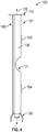
Figure 4 is an external side view of the positioning device ofFigure 1 ; -
Figure 5 is an external side view of the top of the dual chamber orifice flowmeter having a positioning device ofFigure 1 ; -
Figure 6 shows a partial cross-sectional side view of the positioning device and the top of the flowmeter ofFigure 5 ; -
Figure 7 shows a partial cross-sectional side view of the positioning device and the top of the flowmeter ofFigure 5 ; -
Figure 8 shows a partial cross-sectional back view of the positioning device and the top of the flowmeter ofFigure 5 ; -
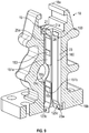
Figure 9 shows a partial cross-sectional view in perspective of the positioning device and the top of the flowmeter ofFigure 5 ; -
Figure 10 shows an external perspective view of a two-piece embodiment of the positioning device ofFigure 1 in accordance with the principles described herein; -
Figure 11 is an external front view of the two-piece embodiment of the positioning device shown inFigure 10 ; -
Figure 12 is an external side view of the two-piece embodiment of the positioning device ofFigure 10 ; -
Figure 13 shows a partial cross-sectional side view of the two-piece embodiment of the positioning device ofFigure 10 within the top of the flowmeter ofFigure 1 ; -
Figure 14 shows a partial cross-sectional side view of the two-piece embodiment of the positioning device ofFigure 10 within the top of the flowmeter ofFigure 1 ; -
Figure 15 shows a partial cross-sectional back view of the two-piece embodiment of the positioning device ofFigure 10 within the top of the flowmeter ofFigure 1 ; and -
Figure 16 shows a partial cross-sectional view in perspective of the two-piece embodiment of the positioning device ofFigure 10 within the top of the flowmeter ofFigure 1 . - The following discussion is directed to various exemplary embodiments. However, one skilled in the art will understand that the discussion of any embodiment is meant only to be exemplary of that embodiment, and not intended to suggest that the scope of the disclosure is limited to that embodiment.
- Certain terms are used throughout the following description and in the claims to refer to particular features or components. As one skilled in the art will appreciate, different persons may refer to the same feature or component by different names. This document does not intend to distinguish between components or features that differ in name but not function. The drawing figures are not necessarily to scale. Certain features and components herein may be shown exaggerated in scale or in somewhat schematic form and some details of conventional elements may not be shown in interest of clarity and conciseness.
- In the following discussion and in the claims, the terms "including" and "comprising" are used in an open-ended fashion, and thus should be interpreted to mean "including, but not limited to ...." Also, the term "couple" or "couples" is intended to mean either an indirect or direct connection. Thus, if a first device couples to a second device, that connection may be through a direct connection, or through an indirect connection via other devices, components, and connections. In addition, as used herein, the terms "axial" and "axially" generally mean along or parallel to a central axis (e.g., central axis of a body or a port), while the terms "radial" and "radially" generally mean perpendicular to the central axis. For instance, an axial distance refers to a distance measured along or parallel to the central axis, and a radial distance means a distance measured perpendicular to the central axis.
- Referring now to
Figure 1 , a partial sectional view of an example of anorifice flowmeter 12, more specifically a dual chamber orifice fitting, is illustrated. Orificeflowmeter 12 includesbody 16 andtop 18.Body 16 encloseslower chamber 20, which is in fluid communication with the interior or bore ofpipeline 34, which extends along alongitudinal axis 35 on either side offlowmeter 12. Aflow passage 37 extends through and includes the interior of thepipeline 34 andlower chamber 20. Top 18 enclosesupper chamber 22, which houses a plate carrier guide or insert 100, and is connected tobody 16 bybolts 17. Insert 100 is an example of a positioning device.Aperture 30 defines an opening connectingupper chamber 22 tolower chamber 20.Aperture 30 is configured to isolateupper chamber 22 and theinsert 100 fromlower chamber 20 and from flow passage when in a closed configuration, andaperture 30 is configured to allow communication among these features when in an open configuration. Valveseat 24 is connected totop 18 and provides a sealing engagement with aslide valve plate 56, which is slidably actuated by rotatinggear shaft 54.Lower drive 36 andupper drive 38 operate to moveorifice plate carrier 32 vertically withinflowmeter 12. - Orifice 31 is located on an
orifice plate 33 supported byorifice plate carrier 32. Orificeplate carrier 32 is shown in a metering position in axial alignment with the interior ofpipeline 34.Flow passage 37 extends throughorifice 31 whenorifice plate carrier 32 andorifice plate 33 are seated inlower chamber 20. To removeorifice plate carrier 32 fromflowmeter 12, thegear shaft 54 is rotated to slidevalve plate 56 laterally and away fromvalve seat 24 and openaperture 30. Onceaperture 30 is opened,lower drive 36 is actuated to moveorifice plate carrier 32 upwards intoupper chamber 22. Onceorifice plate carrier 32 is entirely withinupper chamber 22,aperture 30 is closed to isolate theupper chamber 22,insert 100, andcarrier 32 frompipeline 34 andlower chamber 20; in other words, to isolate those features fromflow passage 37. Any pressure withinupper chamber 22 can then be relieved andorifice plate carrier 32 can be removed fromflowmeter 12 by looseningclamping bar screws 48 and removingclamping bar 44 and sealingbar 40 fromtop 18. - Referring now to
Figures 2-4 ,insert 100 includeshousing 101 having acentral axis 105 and a first orupper end 110, a second orlower end 120, afirst side 130, asecond side 140, afront side 150, and aback side 160 to form a cavity or interior through-passage 170, in accordance with the principles described herein is shown. - In the present embodiment, the
upper end 110 is disposed opposite thelower end 120 and comprises an opening 115 surrounded by a lip orprotrusion 118 that extends radially outward from opening 115. Lip orprotrusion 118 includes two throughholes hole 118a is disposed proximate thefirst side 130 and the second throughhole 118b is disposed proximate thesecond side 140. In other embodiments, thelip 118 may have three or more through holes, or may have no through holes. In other embodiments, the upper end may comprise a plurality of protrusions 118 (seeFigures 10-16 ); in still other embodiments, the upper end may comprise a plurality ofprotrusions 118 with throughholes protrusions 118 disposed proximate thefirst side 130 andsecond side 140. - Referring still to
Figures 2-4 ,first side 130 is generally parallel to and spaced apart fromsecond side 140; thefirst side 130 and thesecond side 140 are generally rectangular and thus, generally perpendicular tolip 118 ofupper end 110. According to the invention,first side 130 andsecond side 140 includecutouts Cutouts upper end 110 and thelower end 120, and proximate thefront side 150. In other embodiments, the cutouts may be located closer to theupper end 110 or closer to thelower end 120. In the present embodiment, thecutouts cutouts - The
front side 150 is generally parallel to and spaced apart from theback side 160; thefront side 150 and backside 160 are generally rectangular and thus, generally perpendicular to thelip 118 ofupper end 110, and generally perpendicular to the first andsecond sides front side 150 comprises a firstelongate portion 151, a secondelongate portion 152, anupper cross panel 153 and alower cross panel 154. The firstelongate portion 151 is disposed adjacentfirst side 130 and extends axially fromupper end 110 tolower end 120. The secondelongate portion 152 is disposed adjacentsecond side 140 and extends axially fromupper end 110 tolower end 120.Cutout 131 offirst side 130 extends to the firstelongate portion 151, separating the first elongate portion into anupper portion 151a and alower portion 151b; similarly,cutout 141 ofsecond side 140 extends to the secondelongate portion 152, separating the second elongate portion into anupper portion 152a and alower portion 152b. Theupper cross panel 153 extends from theupper portion 151a of the firstelongate portion 151 to theupper portion 152a of the secondelongate portion 152, and thelower cross panel 154 extends from thelower portion 151b of the firstelongate portion 151 to thelower portion 152b of the secondelongate portion 152. In alternative embodiments, thefront side 150 may comprise additional panels and/or the elongate portions may be any suitable width. - The
lower end 120 comprises anopening 128 and a plurality of protrusions or extensions 121-125. Thecavity 170 extends from theopening 115 in theupper end 110 to theopening 128 in thelower end 120. Afirst protrusion 121 extends axially downward and radially outward fromfirst side 130. Asecond protrusion 122 extends axially downward and radially outward fromsecond side 140. Athird protrusion 123 and afourth protrusion 124 extend axially downward and radially outward from thefront side 150, thethird protrusion 123 is proximate thefirst side 130 and thefourth protrusion 124 is proximate thesecond side 140. The third andfourth protrusions angular portion front side 150, and a generallyvertical portion angular portion vertical portion bore vertical portion fifth protrusion 125 extends from approximately thefirst side 130 to thesecond side 140 and comprises anangular portion 125a that extends axially downward and radially outward from theback side 160, and a generallyvertical portion 125b that extends axially downward from theangular portion 125a. In the present embodiment, thevertical portion 125b has two throughbores vertical portion 125b, one disposed proximate the first side 130 (125c shown inFigure 9 ) and one disposed proximate the second side 140 (125d). - Referring now to
Figures 5-9 , an example of a top 18 of aflowmeter 12 with a plate carrier guide or insert 100 installed is shown.Insert 100 is disposed inupper chamber 22 oftop 18, the top 18 having anupper end 18a and alower end 18b. Theback side 160 is disposed proximate aback side wall 23 of the upper chamber 22 (Figures 6 and9 ). Thefront side 150 is disposed proximate afront side wall 25 of theupper chamber 22, the upper chamberfront side wall 25 having anupper portion 25a and alower portion 25b separated by acurved portion 25c (Figures 6 and9 ); thecurved portion 25c offront side wall 25 is configured to house theupper drive 38 andcorresponding gears 38a and allow unobstructed rotation of theupper drive 38 and gears 38a therein (seeFigure 1 ). Theupper portions elongate portions upper cross panel 153 ofinsert 100 are disposed proximateupper portion 25a of upper chamberfront side wall 25. Further,lower portions elongate portions lower cross panel 154 ofinsert 100 are disposed proximatelower portion 25b of upper chamberfront side wall 25. - The
first side 130 is disposed proximate afirst side wall 26 of theupper chamber 22, and thesecond side 140 is disposed proximate asecond side wall 27 of upper chamber 22 (Figure 8 ). Thelip 118 ofupper end 110 is adjacent anupper surface 19 of top 18 (Figure 9 ); the lip may rest on topupper surface 19, in anindentation 21 in the topupper surface 19, or on a seal, such as, for example, a gasket or an elastomer member (not shown) disposed between either thelip 118 and the topupper surface 19 or between thelip 118 and theindention 21. Theindentation 21 further includes twobores first bore 21a is disposed proximate afirst side 18c of top 18 and thesecond bore 21b is disposed proximate asecond side 18d of top 18 (Figures 5 and9 ). Thebottom end 120 is disposed proximatelower end 18b and adjacent theback side wall 23,front side wall 25,first side wall 26, andsecond side wall 27 of the upper chamber 22 (Figures 6 and8 ). In particular, thevertical portion 125b of thefifth protrusion 125 is adjacent the upper chamber backside wall 23 such that throughbore 125c is aligned with corresponding threadedbore 23a in theback side wall 23, and throughbore 125d is aligned with corresponding threadedbore 23b in the back side wall 23 (Figures 6 and 7 ). Thevertical portion 123b of thethird protrusion 123 is adjacent thelower portion 25b offront side wall 25 proximate thefirst side wall 26 such that throughbore 123c is aligned with a corresponding threadedbore 25d in thelower portion 25b offront side wall 25 proximate first side wall 26 (Figures 6-8 ). Thevertical portion 124b of thefourth protrusion 124 is adjacent thelower portion 25b offront side wall 25 proximate thesecond side wall 27 such that throughbore 124c is aligned with a corresponding threadedbore 25e in thelower portion 25b offront side wall 25 proximate second side wall 27 (Figures 6-8 ). Thefirst protrusion 121 is disposed proximate thefirst side wall 26, and thesecond protrusion 122 is disposed proximate thesecond side wall 27. - The
insert 100 may be secured to theupper chamber 22 by any fastening means known in the art including, but not limited to threaded rods, bolts, screws, welding, and by being held in place when the sealingbar 40 and clampingbar 44 are installed. When installed, the sealingbar 40 is adjacentupper end 110 and may contactupper end 110. In the present embodiment, insert 100 is secured to top 18 with screws passing throughbores top lip 118 and engaging threadedbores top 18.Insert 100 is further secured to top 18 with screws passing throughbores vertical portions bores front side wall 25 oftop 18.Insert 100 is further secured to top 18 with screws passing throughbores vertical portion 125b and engaging threadedbores back side wall 23 oftop 18. - Referring again to
Figure 1 , the operation ofplate carrier 32 will be described for an embodiment having a plate carrier guide or insert 100 installed within the top 18 offlowmeter 12. As previously described, thelower drive 36 and theupper drive 38 operate to move theorifice plate carrier 32 vertically withinflowmeter 12. The following discussion is directed to the movement of theorifice carrier plate 32 from thelower chamber 20 to theupper chamber 22; for simplicity, intermediary steps such as actuatingslide valve plate 56 or removing clampingbar 44 and sealingbar 40 will not be described. One skilled in the art will appreciate that aside from directional differences, a discussion directed to the movement of theorifice carrier plate 32 from theupper chamber 22 to thelower chamber 20 would be substantially similar. Eachdrive gears corresponding grooves 32a on theorifice plate carrier 32.Grooves 32a are disposed in two columns on opposite ends of theorifice plate carrier 32. In the example ofFigure 1 ,grooves 32a include a plurality of linearly aligned gear teeth extending in the direction thatcarrier 32 travels. Each column ofgrooves 32a forms a rack, which may also be called a gear rack. Thegears orifice plate carrier 32 is located in thelower chamber 20, lower drive gears 36a engage the orificeplate carrier grooves 32a such that actuatinglower drive 36 causes theorifice plate carrier 32 to move vertically upward from the lower chamber intoupper chamber 22. When theorifice plate carrier 32 moves into theupper chamber 22, the upper drive gears 38a engage the orificeplate carrier grooves 32a throughcutouts 131, 141 (Figure 2 ) in thefirst side 130 extending to the firstelongate portion 151 of thefront side 150 and thesecond side 140 extending to the secondelongate portion 152 of thefront side 150 ofinsert 100, and when theorifice plate carrier 32 reaches a certain height in theupper chamber 22, the lower drive gears 36a disengage the orificeplate carrier grooves 32a. Continuing to referenceFigure 1 , insert 100 centers and guides theorifice plate carrier 32 while it travels throughupper chamber 22. The actuation of theupper drive 38 further raises theorifice plate carrier 32 to extend beyondtop 18 oforifice meter 12 for removal. In alternative embodiments, thelower drive 36 andgear shaft 54 offlowmeter 12 may comprise components other than nuts having varying geometry that will actuate theslide valve plate 56. - As the
orifice plate 33 provides measurement of the stream flowing withinpipeline 34 and through theflowmeter 12, theorifice plate 33 should be centered for accuracy. However, during the fabrication of theflowmeter 12, variations in wall thickness and the contours of the internal chambers can make it difficult to position anorifice plate carrier 32 for insertion and alignment. For theorifice plate carrier 32 to be inserted or removed from theflowmeter 12, thegrooves 32a of theorifice plate carrier 32 need to remain in contact and engaged with thegears 38a of theupper drive 38 as theorifice plate carrier 32 travels through the top 18. Theinsert 100 allows for consistent and repeatable alignment in guiding theorifice plate carrier 32 in and out offlowmeter 12 regardless of variations in the wall thickness and contours of the internal chambers of the flowmeter. - The plate carrier guide or insert 100 may be a one piece construction, as illustrated in
Figures 2-9 , or may be a two-piece construction, as illustrated inFigures 10-16 . Like parts are designated with like reference numerals. The embodiment ofinsert 100 introduced inFigure 10 includes first and second pieces or guidechannels axis 105. Thesecond guide channel 180b is separated from and is not attached to thefirst guide channel 180a. Thefirst side 130 and associated features are located inguide channel 180a.Second side 140 and associated features are located inguide channel 180b. Theguide channels flow meter 12 separately, one-at-a-time. As shown best inFigure 10 andFigure 15 ,guide channels passage 170 from theupper end 110 to thelower end 120. Through-passage 172 extends within and betweenguide channels insert 100 is installed within top 18 (Figure 15 ), through-passage 172 extends within theupper chamber 22 and is configured to receiveorifice plate carrier 32, allowing it to enter and to pass-throughinsert 100. - In other embodiments, the
plate carrier guide 100 may be formed from any number of pieces that maintains the structural integrity of theplate carrier guide 100. Aplate carrier 32 is typically aligned in thetop chamber 22 through the use of pads that are cast into the top chamber. The cast features can be difficult to control during casting and can restrict the geometry of the opening in the top chamber. With the use of theplate carrier guide 100 to guide theplate carrier 32, protrusions or pads cast into the upper chamber as positioning devices are no longer needed. Thus, theplate carrier guide 100 may be used in alternative casting designs that may be easier to manufacture. For example, one or more of theinner walls upper chamber 22 may be smooth or flat, being free of protrusions. Some of these embodiments may include the walls may be described as being generally smooth or generally flat. Some embodiments may include an oval design for the shape of the upper chamber 22 (for example, having an oval-shaped cross-section that extends away fromlower chamber 20 oraxis 35 to form thewalls - While exemplary embodiments have been shown and described, modifications thereof can be made by one skilled in the art without departing from the scope or teachings herein. The embodiments described herein are exemplary only and are not limiting. Many variations and modifications of the systems, apparatus, and processes described herein are possible. For example, the relative dimensions of various parts, the materials from which the various parts are made, and other parameters can be varied. Accordingly, the scope of protection is not limited to the embodiments described herein, but is only limited by the claims.
Claims (15)
- An apparatus for positioning an orifice plate (33) in an orifice flowmeter (12), the apparatus comprising:an insert (100) having a through-passage (170) extending from a first end (110) to a second end (120), the second end (120) having extensions (121-125) configured to secure the apparatus to an internal portion of the orifice flowmeter (12);characterized bya first side (130) of the insert (100) having a first cutout (131) to allow access to the through-passage (170); anda second side (140) of the insert (100) having a second cutout (141) to allow access to the through-passage (170);wherein the through-passage (170) is configured to allow the orifice plate (33) installed on an orifice plate carrier (32) to pass therethrough; andwherein the first and second cutouts (131, 141) are configured to allow a gear (38a) to pass therethrough, the gear (38a) configured to engage the orifice plate carrier (32).
- The apparatus of claim 1, wherein the first end (110) further includes a lip (118) configured to engage a top surface (19) of the orifice flowmeter (12) or a plurality of protrusions (118) configured to engage a top surface (19) of the orifice flowmeter (12).
- The apparatus of claim 1, further comprising a seal disposed between the first end (110) and a top surface (19) of the orifice flowmeter (12).
- The apparatus of claim 1, wherein the extensions (121-125) are welded to the internal portion of the orifice flowmeter (12); or
wherein the extensions (121-125) comprise through holes in alignment with bores in the internal portion of the orifice flowmeter (12), the through holes and bores are configured to accept a fastener therein. - The apparatus of claim 1, wherein the insert (100) is retained in the orifice flowmeter (12) with a sealing bar (40) disposed adjacent the first end (110), wherein the sealing bar (40) is configured to attach to the orifice flowmeter (12) with clamping bar screws (48); or
wherein the insert (100) comprises a first piece (180a) and a second piece (180b) separate from the first piece (180a), the first side (130) disposed on the first piece (180a) and the second side (140) disposed on the second piece (180b). - An orifice flowmeter (12) comprising:a body (16) having a lower chamber (20) and a top (18) having an upper chamber (22);an orifice plate (33) disposed in an orifice plate carrier (32), the carrier (32) having a first row of grooves (32a) disposed on a first end of the orifice plate carrier (32) and second row of grooves (32a) disposed on a second end of the orifice plate carrier (32);a gear (38a) disposed in the upper chamber (22) configured to engage the orifice plate carrier (32);
the apparatus of claim 1; and wherein the insert (100) is disposed in the upper chamber (22), the insert (100) having a first opening (115) in the first end (110), a second opening (128) and a plurality of protrusions in the second end (120), where the through-passage (170) extends from the first opening (115) to the second opening (128). - The flowmeter (12) of claim 6, wherein the first end (110) further includes a lip (118) configured to engage a top surface (19) of the orifice flowmeter (12) or a plurality of protrusions (118) configured to engage a top surface (19) of the orifice flowmeter (12).
- The flowmeter (12) of claim 6, wherein the insert (100) is rectangular.
- The flowmeter (12) of claim 6, wherein the upper chamber (22) includes an oval-shaped cross-section.
- The flowmeter (12) of claim 6, wherein the first end (110) is configured to engage a seal disposed between the first end (110) and a top surface (19) of the orifice flowmeter (12).
- The flowmeter (12) of claim 6, wherein the protrusions (118) are welded to an internal portion of the upper chamber (22) or wherein the protrusions (118) comprise through holes in alignment with bores in an internal portion of the upper chamber (22), the through holes and bores are configured to accept a fastener therein.
- The flowmeter (12) of claim 6, further comprising a sealing bar (14) disposed at an upper end of the top (18) and configured to attach to the top (18) with clamping bar screws (148) and retain the insert (100) in the upper chamber (22).
- The flowmeter (12) of claim 6, wherein the insert (100) comprises a first piece (180a) and a second piece (180b), the first side (130) disposed on the first piece (180a) and the second side (140) disposed on the second piece (180b).
- The flowmeter (12) of claim 6 wherein the body (16) further comprises:a flow passage (37) that extends through the lower chamber (20); andan aperture (30) connecting the upper chamber (22) to lower chamber (20), the aperture (30) configured to isolate the upper chamber (22) and the insert (100) from the flow passage (37).
- A method of positioning an orifice plate carrier (32) in an orifice flowmeter (12), the method comprising:engaging grooves (32a) on opposite ends of the orifice plate carrier (32) with a first drive gear (38a) and a second drive gear (38a), where the orifice plate carrier (32) is disposed in a through-passage (170) of an insert (100), characterized in that the first drive gear (38a) passes through a first cutout (131) in the insert (100), and the second drive gear (38a) passes through a second cutout (141) in the insert (100);actuating the first and second drive gears (38a) via an upper drive (38); andpassing the orifice plate carrier (32) through the insert (100).
Applications Claiming Priority (2)
| Application Number | Priority Date | Filing Date | Title |
|---|---|---|---|
| US201562149256P | 2015-04-17 | 2015-04-17 | |
| PCT/US2016/027328 WO2016168326A1 (en) | 2015-04-17 | 2016-04-13 | Plate carrier guide for an orifice fitting |
Publications (3)
| Publication Number | Publication Date |
|---|---|
| EP3283852A1 EP3283852A1 (en) | 2018-02-21 |
| EP3283852A4 EP3283852A4 (en) | 2019-01-30 |
| EP3283852B1 true EP3283852B1 (en) | 2020-05-06 |
Family
ID=57126409
Family Applications (1)
| Application Number | Title | Priority Date | Filing Date |
|---|---|---|---|
| EP16780646.2A Not-in-force EP3283852B1 (en) | 2015-04-17 | 2016-04-13 | Plate carrier guide for an orifice fitting |
Country Status (7)
| Country | Link |
|---|---|
| US (1) | US9841303B2 (en) |
| EP (1) | EP3283852B1 (en) |
| CN (2) | CN106052782B (en) |
| CA (1) | CA2982949C (en) |
| MX (1) | MX395140B (en) |
| RU (1) | RU2705659C2 (en) |
| WO (1) | WO2016168326A1 (en) |
Families Citing this family (5)
| Publication number | Priority date | Publication date | Assignee | Title |
|---|---|---|---|---|
| MX395140B (en) * | 2015-04-17 | 2025-03-24 | Daniel Opco Llc | CARRIER GUIDE PLATE FOR ONE MOUNTING HOLE |
| US10545040B2 (en) * | 2018-02-02 | 2020-01-28 | Daniel Measurment And Control, Inc. | Flowmeter and orifice plate carrier assembly therefor |
| US10794741B2 (en) * | 2018-10-06 | 2020-10-06 | Bell Technologies, LLC | Flow measurement insert and system for use with orifice fitting |
| CN112082613B (en) * | 2020-08-28 | 2021-09-10 | 武汉理工大学 | A kind of oval gear flowmeter auxiliary starting system |
| CN120445341B (en) * | 2025-07-07 | 2025-09-09 | 四川凯创机电设备有限公司 | An orifice flowmeter |
Family Cites Families (20)
| Publication number | Priority date | Publication date | Assignee | Title |
|---|---|---|---|---|
| US1965826A (en) * | 1931-05-06 | 1934-07-10 | Paul P Daniel | Orifice meter plate housing |
| US4531539A (en) * | 1981-11-23 | 1985-07-30 | General Signal Corporation | Control valve for flow of solids |
| US4478251A (en) * | 1982-08-02 | 1984-10-23 | Daniel Industries, Inc. | Orifice fitting seal assembly |
| US4693452A (en) * | 1986-03-12 | 1987-09-15 | Triten Corporation | Valve |
| JP2524701B2 (en) * | 1986-04-18 | 1996-08-14 | 言彦 世古口 | Orifice plate exchange device for throttle flow meter |
| US5085250A (en) * | 1990-12-18 | 1992-02-04 | Daniel Industries, Inc. | Orifice system |
| US5069252A (en) * | 1990-12-18 | 1991-12-03 | Daniel Industries, Inc. | Orifice system intermediate interface |
| US5181542A (en) * | 1991-02-22 | 1993-01-26 | Daniel Industries, Inc. | Orifice system mounting assembly |
| US5318073A (en) * | 1992-06-09 | 1994-06-07 | Daniel Industries, Inc. | Orifice plate seal |
| RU2150680C1 (en) * | 1995-08-17 | 2000-06-10 | Жибуртович Генрих Георгиевич | Gear for location and mounting of diaphragms of flowmeter |
| US5836356A (en) * | 1996-03-12 | 1998-11-17 | Mueller Steam Specialty, A Divison Of Core Industries, Inc. | Dual chamber orifice fitting |
| US6109590A (en) * | 1998-02-12 | 2000-08-29 | Tapco International, Inc. | Iron ore slide valve with internal support clamp |
| US6871666B1 (en) * | 2004-05-19 | 2005-03-29 | Daniel Industries, Inc. | Bi-directional dual chamber orifice fitting |
| US7837176B2 (en) * | 2004-05-19 | 2010-11-23 | Daniel Measurement And Control, Inc. | Dual chamber orifice fitting plate support |
| US7870873B2 (en) * | 2006-02-13 | 2011-01-18 | Daniel Industries, Inc. | Dual chamber orifice fitting isolation valve |
| US7461563B1 (en) * | 2007-09-07 | 2008-12-09 | Daniel Measurement And Control, Inc. | Bi-directional orifice plate assembly |
| US20090194182A1 (en) * | 2008-01-31 | 2009-08-06 | Daniel Measurement And Control, Inc. | Dual chamber orifice fitting body |
| US8215340B2 (en) * | 2008-02-19 | 2012-07-10 | Daniel Measurement And Control, Inc. | Orifice plate carrier |
| CA2967310C (en) * | 2014-11-07 | 2023-01-03 | Daniel Measurement And Control, Inc. | Orifice flowmeter security device |
| MX395140B (en) * | 2015-04-17 | 2025-03-24 | Daniel Opco Llc | CARRIER GUIDE PLATE FOR ONE MOUNTING HOLE |
-
2016
- 2016-04-13 MX MX2017013361A patent/MX395140B/en unknown
- 2016-04-13 WO PCT/US2016/027328 patent/WO2016168326A1/en not_active Ceased
- 2016-04-13 RU RU2017137952A patent/RU2705659C2/en active
- 2016-04-13 US US15/098,014 patent/US9841303B2/en not_active Expired - Fee Related
- 2016-04-13 EP EP16780646.2A patent/EP3283852B1/en not_active Not-in-force
- 2016-04-13 CA CA2982949A patent/CA2982949C/en active Active
- 2016-04-15 CN CN201610237287.9A patent/CN106052782B/en not_active Expired - Fee Related
- 2016-04-15 CN CN201620319786.8U patent/CN205958045U/en not_active Withdrawn - After Issue
Non-Patent Citations (1)
| Title |
|---|
| None * |
Also Published As
| Publication number | Publication date |
|---|---|
| CN106052782A (en) | 2016-10-26 |
| US9841303B2 (en) | 2017-12-12 |
| MX395140B (en) | 2025-03-24 |
| EP3283852A4 (en) | 2019-01-30 |
| RU2017137952A (en) | 2019-05-17 |
| CN205958045U (en) | 2017-02-15 |
| RU2705659C2 (en) | 2019-11-11 |
| US20160305801A1 (en) | 2016-10-20 |
| CN106052782B (en) | 2019-06-07 |
| WO2016168326A1 (en) | 2016-10-20 |
| RU2017137952A3 (en) | 2019-08-30 |
| CA2982949A1 (en) | 2016-10-20 |
| MX2017013361A (en) | 2018-11-09 |
| EP3283852A1 (en) | 2018-02-21 |
| CA2982949C (en) | 2022-10-25 |
Similar Documents
| Publication | Publication Date | Title |
|---|---|---|
| CA2982949C (en) | Plate carrier guide for an orifice fitting | |
| EP3230695B1 (en) | Multi- double block and bleed system for an orifice fitting | |
| KR20160065812A (en) | A flow control system and control valve having closure assistance | |
| BR112013001604B1 (en) | VALVE WITH BALANCED PRESSURE WITH END SEAL OF DIAPHRAGM VALVE ELEMENT | |
| JP2006009969A (en) | Flow path block for accumulated gas control device and its manufacturing method and accumulated gas control device | |
| JP2023520282A (en) | Valve body assembly and composite valve having the same | |
| EP2167855B1 (en) | Msm component and associated gas panel assembly | |
| EP1715234B1 (en) | Rotary ball valve assembly | |
| CN106370243B (en) | Orifice device and method for removing orifice plate from or installing orifice plate in orifice device | |
| CA2567186C (en) | Dual chamber orifice fitting plate support | |
| JP5465703B2 (en) | Flow sensor | |
| JP4395641B2 (en) | Fluid control device | |
| JP5557592B2 (en) | Connection joint and connection structure | |
| US20220221098A1 (en) | Strainer | |
| CN218818259U (en) | Removable Filter Elements and Seal Valves for Removable Filter Elements | |
| CN205209573U (en) | Safety device and orifice flowmeter who has safety device | |
| NL2014629A (en) | Orifice assembly for a differential pressure meter. | |
| JP6226792B2 (en) | On-off valve and gas meter | |
| AU2022256238A1 (en) | Modular valve assemblies with optional swing out | |
| US8127792B2 (en) | Pressure equalization system for a bi-directional orifice fitting | |
| KR101718332B1 (en) | Anti-surge valve used for gas pipeline | |
| NL2018493B1 (en) | Orifice carrier flange | |
| JP2026514084A (en) | Valve block for solution management system for bioprocesses | |
| US20100000332A1 (en) | Orifice Fitting With a Drainage System | |
| JP3959400B2 (en) | Micro valve |
Legal Events
| Date | Code | Title | Description |
|---|---|---|---|
| STAA | Information on the status of an ep patent application or granted ep patent |
Free format text: STATUS: THE INTERNATIONAL PUBLICATION HAS BEEN MADE |
|
| PUAI | Public reference made under article 153(3) epc to a published international application that has entered the european phase |
Free format text: ORIGINAL CODE: 0009012 |
|
| STAA | Information on the status of an ep patent application or granted ep patent |
Free format text: STATUS: REQUEST FOR EXAMINATION WAS MADE |
|
| 17P | Request for examination filed |
Effective date: 20171108 |
|
| AK | Designated contracting states |
Kind code of ref document: A1 Designated state(s): AL AT BE BG CH CY CZ DE DK EE ES FI FR GB GR HR HU IE IS IT LI LT LU LV MC MK MT NL NO PL PT RO RS SE SI SK SM TR |
|
| AX | Request for extension of the european patent |
Extension state: BA ME |
|
| DAV | Request for validation of the european patent (deleted) | ||
| DAX | Request for extension of the european patent (deleted) | ||
| RIN1 | Information on inventor provided before grant (corrected) |
Inventor name: JAY, GREGORY THERON Inventor name: CROUCH, JUSTIN BLAKE |
|
| A4 | Supplementary search report drawn up and despatched |
Effective date: 20190107 |
|
| RIC1 | Information provided on ipc code assigned before grant |
Ipc: F16K 3/316 20060101ALI20181221BHEP Ipc: G01F 1/42 20060101AFI20181221BHEP |
|
| STAA | Information on the status of an ep patent application or granted ep patent |
Free format text: STATUS: EXAMINATION IS IN PROGRESS |
|
| 17Q | First examination report despatched |
Effective date: 20190903 |
|
| GRAP | Despatch of communication of intention to grant a patent |
Free format text: ORIGINAL CODE: EPIDOSNIGR1 |
|
| STAA | Information on the status of an ep patent application or granted ep patent |
Free format text: STATUS: GRANT OF PATENT IS INTENDED |
|
| INTG | Intention to grant announced |
Effective date: 20191128 |
|
| GRAS | Grant fee paid |
Free format text: ORIGINAL CODE: EPIDOSNIGR3 |
|
| GRAA | (expected) grant |
Free format text: ORIGINAL CODE: 0009210 |
|
| STAA | Information on the status of an ep patent application or granted ep patent |
Free format text: STATUS: THE PATENT HAS BEEN GRANTED |
|
| AK | Designated contracting states |
Kind code of ref document: B1 Designated state(s): AL AT BE BG CH CY CZ DE DK EE ES FI FR GB GR HR HU IE IS IT LI LT LU LV MC MK MT NL NO PL PT RO RS SE SI SK SM TR |
|
| REG | Reference to a national code |
Ref country code: GB Ref legal event code: FG4D |
|
| REG | Reference to a national code |
Ref country code: CH Ref legal event code: EP Ref country code: AT Ref legal event code: REF Ref document number: 1267504 Country of ref document: AT Kind code of ref document: T Effective date: 20200515 |
|
| REG | Reference to a national code |
Ref country code: IE Ref legal event code: FG4D |
|
| REG | Reference to a national code |
Ref country code: DE Ref legal event code: R096 Ref document number: 602016035942 Country of ref document: DE |
|
| REG | Reference to a national code |
Ref country code: LT Ref legal event code: MG4D |
|
| REG | Reference to a national code |
Ref country code: NL Ref legal event code: MP Effective date: 20200506 |
|
| PG25 | Lapsed in a contracting state [announced via postgrant information from national office to epo] |
Ref country code: NO Free format text: LAPSE BECAUSE OF FAILURE TO SUBMIT A TRANSLATION OF THE DESCRIPTION OR TO PAY THE FEE WITHIN THE PRESCRIBED TIME-LIMIT Effective date: 20200806 Ref country code: LT Free format text: LAPSE BECAUSE OF FAILURE TO SUBMIT A TRANSLATION OF THE DESCRIPTION OR TO PAY THE FEE WITHIN THE PRESCRIBED TIME-LIMIT Effective date: 20200506 Ref country code: FI Free format text: LAPSE BECAUSE OF FAILURE TO SUBMIT A TRANSLATION OF THE DESCRIPTION OR TO PAY THE FEE WITHIN THE PRESCRIBED TIME-LIMIT Effective date: 20200506 Ref country code: IS Free format text: LAPSE BECAUSE OF FAILURE TO SUBMIT A TRANSLATION OF THE DESCRIPTION OR TO PAY THE FEE WITHIN THE PRESCRIBED TIME-LIMIT Effective date: 20200906 Ref country code: GR Free format text: LAPSE BECAUSE OF FAILURE TO SUBMIT A TRANSLATION OF THE DESCRIPTION OR TO PAY THE FEE WITHIN THE PRESCRIBED TIME-LIMIT Effective date: 20200807 Ref country code: SE Free format text: LAPSE BECAUSE OF FAILURE TO SUBMIT A TRANSLATION OF THE DESCRIPTION OR TO PAY THE FEE WITHIN THE PRESCRIBED TIME-LIMIT Effective date: 20200506 Ref country code: PT Free format text: LAPSE BECAUSE OF FAILURE TO SUBMIT A TRANSLATION OF THE DESCRIPTION OR TO PAY THE FEE WITHIN THE PRESCRIBED TIME-LIMIT Effective date: 20200907 |
|
| PG25 | Lapsed in a contracting state [announced via postgrant information from national office to epo] |
Ref country code: BG Free format text: LAPSE BECAUSE OF FAILURE TO SUBMIT A TRANSLATION OF THE DESCRIPTION OR TO PAY THE FEE WITHIN THE PRESCRIBED TIME-LIMIT Effective date: 20200806 Ref country code: RS Free format text: LAPSE BECAUSE OF FAILURE TO SUBMIT A TRANSLATION OF THE DESCRIPTION OR TO PAY THE FEE WITHIN THE PRESCRIBED TIME-LIMIT Effective date: 20200506 Ref country code: LV Free format text: LAPSE BECAUSE OF FAILURE TO SUBMIT A TRANSLATION OF THE DESCRIPTION OR TO PAY THE FEE WITHIN THE PRESCRIBED TIME-LIMIT Effective date: 20200506 Ref country code: HR Free format text: LAPSE BECAUSE OF FAILURE TO SUBMIT A TRANSLATION OF THE DESCRIPTION OR TO PAY THE FEE WITHIN THE PRESCRIBED TIME-LIMIT Effective date: 20200506 |
|
| REG | Reference to a national code |
Ref country code: AT Ref legal event code: MK05 Ref document number: 1267504 Country of ref document: AT Kind code of ref document: T Effective date: 20200506 |
|
| PG25 | Lapsed in a contracting state [announced via postgrant information from national office to epo] |
Ref country code: NL Free format text: LAPSE BECAUSE OF FAILURE TO SUBMIT A TRANSLATION OF THE DESCRIPTION OR TO PAY THE FEE WITHIN THE PRESCRIBED TIME-LIMIT Effective date: 20200506 Ref country code: AL Free format text: LAPSE BECAUSE OF FAILURE TO SUBMIT A TRANSLATION OF THE DESCRIPTION OR TO PAY THE FEE WITHIN THE PRESCRIBED TIME-LIMIT Effective date: 20200506 |
|
| PG25 | Lapsed in a contracting state [announced via postgrant information from national office to epo] |
Ref country code: ES Free format text: LAPSE BECAUSE OF FAILURE TO SUBMIT A TRANSLATION OF THE DESCRIPTION OR TO PAY THE FEE WITHIN THE PRESCRIBED TIME-LIMIT Effective date: 20200506 Ref country code: DK Free format text: LAPSE BECAUSE OF FAILURE TO SUBMIT A TRANSLATION OF THE DESCRIPTION OR TO PAY THE FEE WITHIN THE PRESCRIBED TIME-LIMIT Effective date: 20200506 Ref country code: IT Free format text: LAPSE BECAUSE OF FAILURE TO SUBMIT A TRANSLATION OF THE DESCRIPTION OR TO PAY THE FEE WITHIN THE PRESCRIBED TIME-LIMIT Effective date: 20200506 Ref country code: EE Free format text: LAPSE BECAUSE OF FAILURE TO SUBMIT A TRANSLATION OF THE DESCRIPTION OR TO PAY THE FEE WITHIN THE PRESCRIBED TIME-LIMIT Effective date: 20200506 Ref country code: CZ Free format text: LAPSE BECAUSE OF FAILURE TO SUBMIT A TRANSLATION OF THE DESCRIPTION OR TO PAY THE FEE WITHIN THE PRESCRIBED TIME-LIMIT Effective date: 20200506 Ref country code: SM Free format text: LAPSE BECAUSE OF FAILURE TO SUBMIT A TRANSLATION OF THE DESCRIPTION OR TO PAY THE FEE WITHIN THE PRESCRIBED TIME-LIMIT Effective date: 20200506 Ref country code: RO Free format text: LAPSE BECAUSE OF FAILURE TO SUBMIT A TRANSLATION OF THE DESCRIPTION OR TO PAY THE FEE WITHIN THE PRESCRIBED TIME-LIMIT Effective date: 20200506 Ref country code: AT Free format text: LAPSE BECAUSE OF FAILURE TO SUBMIT A TRANSLATION OF THE DESCRIPTION OR TO PAY THE FEE WITHIN THE PRESCRIBED TIME-LIMIT Effective date: 20200506 |
|
| REG | Reference to a national code |
Ref country code: DE Ref legal event code: R097 Ref document number: 602016035942 Country of ref document: DE |
|
| PG25 | Lapsed in a contracting state [announced via postgrant information from national office to epo] |
Ref country code: PL Free format text: LAPSE BECAUSE OF FAILURE TO SUBMIT A TRANSLATION OF THE DESCRIPTION OR TO PAY THE FEE WITHIN THE PRESCRIBED TIME-LIMIT Effective date: 20200506 Ref country code: SK Free format text: LAPSE BECAUSE OF FAILURE TO SUBMIT A TRANSLATION OF THE DESCRIPTION OR TO PAY THE FEE WITHIN THE PRESCRIBED TIME-LIMIT Effective date: 20200506 |
|
| PLBE | No opposition filed within time limit |
Free format text: ORIGINAL CODE: 0009261 |
|
| STAA | Information on the status of an ep patent application or granted ep patent |
Free format text: STATUS: NO OPPOSITION FILED WITHIN TIME LIMIT |
|
| 26N | No opposition filed |
Effective date: 20210209 |
|
| PG25 | Lapsed in a contracting state [announced via postgrant information from national office to epo] |
Ref country code: SI Free format text: LAPSE BECAUSE OF FAILURE TO SUBMIT A TRANSLATION OF THE DESCRIPTION OR TO PAY THE FEE WITHIN THE PRESCRIBED TIME-LIMIT Effective date: 20200506 |
|
| REG | Reference to a national code |
Ref country code: DE Ref legal event code: R119 Ref document number: 602016035942 Country of ref document: DE |
|
| PG25 | Lapsed in a contracting state [announced via postgrant information from national office to epo] |
Ref country code: MC Free format text: LAPSE BECAUSE OF FAILURE TO SUBMIT A TRANSLATION OF THE DESCRIPTION OR TO PAY THE FEE WITHIN THE PRESCRIBED TIME-LIMIT Effective date: 20200506 |
|
| PG25 | Lapsed in a contracting state [announced via postgrant information from national office to epo] |
Ref country code: LU Free format text: LAPSE BECAUSE OF NON-PAYMENT OF DUE FEES Effective date: 20210413 |
|
| REG | Reference to a national code |
Ref country code: BE Ref legal event code: MM Effective date: 20210430 |
|
| PG25 | Lapsed in a contracting state [announced via postgrant information from national office to epo] |
Ref country code: DE Free format text: LAPSE BECAUSE OF NON-PAYMENT OF DUE FEES Effective date: 20211103 Ref country code: FR Free format text: LAPSE BECAUSE OF NON-PAYMENT OF DUE FEES Effective date: 20210430 Ref country code: LI Free format text: LAPSE BECAUSE OF NON-PAYMENT OF DUE FEES Effective date: 20210430 Ref country code: CH Free format text: LAPSE BECAUSE OF NON-PAYMENT OF DUE FEES Effective date: 20210430 |
|
| REG | Reference to a national code |
Ref country code: GB Ref legal event code: 732E Free format text: REGISTERED BETWEEN 20220127 AND 20220202 |
|
| PG25 | Lapsed in a contracting state [announced via postgrant information from national office to epo] |
Ref country code: IE Free format text: LAPSE BECAUSE OF NON-PAYMENT OF DUE FEES Effective date: 20210413 |
|
| PG25 | Lapsed in a contracting state [announced via postgrant information from national office to epo] |
Ref country code: BE Free format text: LAPSE BECAUSE OF NON-PAYMENT OF DUE FEES Effective date: 20210430 |
|
| PG25 | Lapsed in a contracting state [announced via postgrant information from national office to epo] |
Ref country code: HU Free format text: LAPSE BECAUSE OF FAILURE TO SUBMIT A TRANSLATION OF THE DESCRIPTION OR TO PAY THE FEE WITHIN THE PRESCRIBED TIME-LIMIT; INVALID AB INITIO Effective date: 20160413 |
|
| PGFP | Annual fee paid to national office [announced via postgrant information from national office to epo] |
Ref country code: GB Payment date: 20230321 Year of fee payment: 8 |
|
| PG25 | Lapsed in a contracting state [announced via postgrant information from national office to epo] |
Ref country code: CY Free format text: LAPSE BECAUSE OF FAILURE TO SUBMIT A TRANSLATION OF THE DESCRIPTION OR TO PAY THE FEE WITHIN THE PRESCRIBED TIME-LIMIT Effective date: 20200506 |
|
| PG25 | Lapsed in a contracting state [announced via postgrant information from national office to epo] |
Ref country code: MK Free format text: LAPSE BECAUSE OF FAILURE TO SUBMIT A TRANSLATION OF THE DESCRIPTION OR TO PAY THE FEE WITHIN THE PRESCRIBED TIME-LIMIT Effective date: 20200506 |
|
| PG25 | Lapsed in a contracting state [announced via postgrant information from national office to epo] |
Ref country code: MT Free format text: LAPSE BECAUSE OF FAILURE TO SUBMIT A TRANSLATION OF THE DESCRIPTION OR TO PAY THE FEE WITHIN THE PRESCRIBED TIME-LIMIT Effective date: 20200506 |
|
| GBPC | Gb: european patent ceased through non-payment of renewal fee |
Effective date: 20240413 |
|
| PG25 | Lapsed in a contracting state [announced via postgrant information from national office to epo] |
Ref country code: GB Free format text: LAPSE BECAUSE OF NON-PAYMENT OF DUE FEES Effective date: 20240413 |
|
| PG25 | Lapsed in a contracting state [announced via postgrant information from national office to epo] |
Ref country code: GB Free format text: LAPSE BECAUSE OF NON-PAYMENT OF DUE FEES Effective date: 20240413 |
|
| PG25 | Lapsed in a contracting state [announced via postgrant information from national office to epo] |
Ref country code: TR Free format text: LAPSE BECAUSE OF FAILURE TO SUBMIT A TRANSLATION OF THE DESCRIPTION OR TO PAY THE FEE WITHIN THE PRESCRIBED TIME-LIMIT Effective date: 20200506 |