EP3283186B1 - Steering stabilizing apparatus for a model vehicle - Google Patents
Steering stabilizing apparatus for a model vehicle Download PDFInfo
- Publication number
- EP3283186B1 EP3283186B1 EP16718963.8A EP16718963A EP3283186B1 EP 3283186 B1 EP3283186 B1 EP 3283186B1 EP 16718963 A EP16718963 A EP 16718963A EP 3283186 B1 EP3283186 B1 EP 3283186B1
- Authority
- EP
- European Patent Office
- Prior art keywords
- steering
- curvature
- input
- model vehicle
- user
- Prior art date
- Legal status (The legal status is an assumption and is not a legal conclusion. Google has not performed a legal analysis and makes no representation as to the accuracy of the status listed.)
- Active
Links
Images



Classifications
-
- A—HUMAN NECESSITIES
- A63—SPORTS; GAMES; AMUSEMENTS
- A63H—TOYS, e.g. TOPS, DOLLS, HOOPS OR BUILDING BLOCKS
- A63H17/00—Toy vehicles, e.g. with self-drive; ; Cranes, winches or the like; Accessories therefor
- A63H17/26—Details; Accessories
- A63H17/36—Steering-mechanisms for toy vehicles
-
- A—HUMAN NECESSITIES
- A63—SPORTS; GAMES; AMUSEMENTS
- A63H—TOYS, e.g. TOPS, DOLLS, HOOPS OR BUILDING BLOCKS
- A63H17/00—Toy vehicles, e.g. with self-drive; ; Cranes, winches or the like; Accessories therefor
- A63H17/26—Details; Accessories
- A63H17/36—Steering-mechanisms for toy vehicles
- A63H17/395—Steering-mechanisms for toy vehicles steered by program
-
- A—HUMAN NECESSITIES
- A63—SPORTS; GAMES; AMUSEMENTS
- A63H—TOYS, e.g. TOPS, DOLLS, HOOPS OR BUILDING BLOCKS
- A63H30/00—Remote-control arrangements specially adapted for toys, e.g. for toy vehicles
-
- A—HUMAN NECESSITIES
- A63—SPORTS; GAMES; AMUSEMENTS
- A63H—TOYS, e.g. TOPS, DOLLS, HOOPS OR BUILDING BLOCKS
- A63H30/00—Remote-control arrangements specially adapted for toys, e.g. for toy vehicles
- A63H30/02—Electrical arrangements
- A63H30/04—Electrical arrangements using wireless transmission
-
- B—PERFORMING OPERATIONS; TRANSPORTING
- B62—LAND VEHICLES FOR TRAVELLING OTHERWISE THAN ON RAILS
- B62D—MOTOR VEHICLES; TRAILERS
- B62D15/00—Steering not otherwise provided for
- B62D15/02—Steering position indicators ; Steering position determination; Steering aids
- B62D15/025—Active steering aids, e.g. helping the driver by actively influencing the steering system after environment evaluation
-
- B—PERFORMING OPERATIONS; TRANSPORTING
- B62—LAND VEHICLES FOR TRAVELLING OTHERWISE THAN ON RAILS
- B62D—MOTOR VEHICLES; TRAILERS
- B62D6/00—Arrangements for automatically controlling steering depending on driving conditions sensed and responded to, e.g. control circuits
- B62D6/002—Arrangements for automatically controlling steering depending on driving conditions sensed and responded to, e.g. control circuits computing target steering angles for front or rear wheels
- B62D6/003—Arrangements for automatically controlling steering depending on driving conditions sensed and responded to, e.g. control circuits computing target steering angles for front or rear wheels in order to control vehicle yaw movement, i.e. around a vertical axis
-
- G—PHYSICS
- G05—CONTROLLING; REGULATING
- G05D—SYSTEMS FOR CONTROLLING OR REGULATING NON-ELECTRIC VARIABLES
- G05D1/00—Control of position, course, altitude or attitude of land, water, air or space vehicles, e.g. using automatic pilots
- G05D1/0011—Control of position, course, altitude or attitude of land, water, air or space vehicles, e.g. using automatic pilots associated with a remote control arrangement
-
- G—PHYSICS
- G07—CHECKING-DEVICES
- G07C—TIME OR ATTENDANCE REGISTERS; REGISTERING OR INDICATING THE WORKING OF MACHINES; GENERATING RANDOM NUMBERS; VOTING OR LOTTERY APPARATUS; ARRANGEMENTS, SYSTEMS OR APPARATUS FOR CHECKING NOT PROVIDED FOR ELSEWHERE
- G07C5/00—Registering or indicating the working of vehicles
- G07C5/008—Registering or indicating the working of vehicles communicating information to a remotely located station
Definitions
- the present invention relates to model vehicles and, more particularly, to an electronic system to stabilize steering of the model vehicle.
- RC Radio Controlled
- the Driver controls the vehicle remotely.
- the RC Driver can only detect the vehicle's motion visually.
- the RC Driver cannot feel the vehicle's disturbances such as hitting a raised area of earth.
- the time constants for scaled vehicles are much smaller than the time constants for full sized vehicles.
- the smaller vehicle responds to disturbances and steering inputs much faster than full sized vehicle.
- Electronic steering stability may aid the RC Driver by stabilizing the steering.
- the Driver can focus on larger steering inputs while the electronic steering stability system responds to disturbances around the Driver's steering inputs.
- Some systems treat the steering stability as a "driver assist". These controllers add a limited adjustment to the driver's commanded steering input. This assist drives the yaw rate to zero. For forward travel (where the driver commands 0 (zero) steering angle), adjusting for a zero yaw rate may be exactly what the driver wishes. However, when the Driver commands a turn, the Driver may not want a zero yaw rate. For example, an assist system adds counter steer against the driver's wishes. Embodiments of these types of systems typically include well-known gain scheduling strategies to minimize the counter steer as the driver's steering input increases or throttle input decreases. These systems do not provide the right "feel" as the car seems to be disconnected from the driver.
- US 6241574 discloses a device for influencing the handling characteristics of remote-controlled model cars or model ships, comprising a first input terminal for a first control signal which represents a first command variable which can be specified by a person who controls the vehicle, a sensor means which outputs a second control signal which represents a disturbance variable correlated with the rotational velocity or the lateral acceleration of the model vehicle, and a processing means which is connected with the first input terminal for receiving the first control signal and which has a second input terminal for receiving the second control signal, and which generates a first output signal which represents a first manipulated variable being a function of the first command variable and of the disturbance variable, with the first manipulated variable generated by the processing means being the command variable which as a function of the disturbance variable is limited or modified to a predeterminable degree.
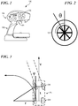
- the reference numeral 100 generally indicates a standard RC Controller used for surface model vehicles, such as model cars and model trucks, for example.
- the RC Controller may have a least a steering wheel 102 and a throttle trigger 104.
- the RC Controller may also have a housing 106, which may include a hand-grip handle 108 for grasping the RC Controller.
- the Driver may use the standard surface RC Controller 100, as shown in Figure 1 , to control a vehicle 200.
- the RC Driver may command steering input using the steering wheel 102.
- the RC Driver may command speed and forward/reverse direction using the throttle trigger 104.
- the RC Driver may thereby produce at least a steering command and a throttle command.
- the RC Controller 100 may transmit the RC Driver's steering and throttle commands to an RC Receiver in the model vehicle 200 being controlled. With no electronic steering stability, the RC Receiver 202 may simply command a Steering Servo to a corresponding angle to steer the front wheels of the vehicle 200. This is illustrated in Figure 2 with respect to the RC steering wheel 102 showing a steering wheel angle ⁇ . As shown in Figure 3 , a land-based, ground model vehicle 200 is illustrated as performing a turn.
- the ground model vehicle 200 may comprise non-steerable wheels 206 and may also comprise steerable wheels 208.
- the non-steerable wheels 206 and the steerable wheels 208 may be spaced apart by a wheelbase distance L.
- the ground model vehicle 200 may be travelling in a forward direction at a speed v.
- the ground model vehicle 200 may steer the steerable wheels 208 at a steering angle ⁇ and execute a turn having a radius r.
- the RC Receiver 202 may execute a control system to compensate for disturbances to the ground model vehicle 200, such as hitting a raised area of earth, for example.
- the RC Driver, operating the ground model vehicle 200 remotely typically cannot feel such disturbances as one would inside a full-size vehicle and may therefore be unable to compensate for such disturbances.
- the time constants for scaled vehicles are much smaller than the time constants for full sized vehicles. The smaller vehicle responds to disturbances and steering inputs much faster than full sized vehicle.
- An Electronic Steering Stability (ESS) system 400 may receive inputs from sensors detecting such disturbances, calculate compensating command values, and may command the Steering Servo with the calculated command to control, in the example shown, the Yaw rate to the Driver's commanded rate.
- ESS Electronic Steering Stability
- the Electronic Steering Stability (ESS) system 400 may be a feedback control system that uses 6-axis MEMS devices (3 axis of rate Gyros and 3 axis of Accelerometers) and, optionally, a speed sensor.
- the control system may use common control methodologies such as Proportional-Integral-Differential (PID) error feedback.
- PID Proportional-Integral-Differential
- the primary controlled output may be Yaw rate or, with a speed sensor, turning curvature.
- the electronic steering stability system may use the steering servo command as the control variable.
- the Electronic Steering Stability (ESS) system may be a standard control system that drives the error or difference between the user input ( u ) and the feedback measurement ( y ) to zero. This is in contrast to the driver assist strategy, which drives the vehicle's yaw rate to 0 (zero) by counter steering, and typically decreases the assist amount inversely with steering input or vehicle speed, using gain scheduling.
- ESS Electronic Steering Stability
- the result may be a heading-hold gyro, which maintains the current direction of a vehicle, together with linear gain scheduling with inverse of speed.
- the result may be the functional equivalent of a simple heading-hold gyro.
- the user may command a certain curvature (1/ r ) turn to the right, or to the left.
- the control system may calculate the difference between commanded curvature and the measured curvature (Yaw Rate / speed). If the difference is positive, the system may command the steering servo to angle the front wheels more in the direction of the turn, to increase the yaw rate. If the difference is negative, the system may command less front wheel angle, to decrease the yaw rate.
- one aspect of the Electronic Steering Stability (ESS) system 400 may be controlling curvature in a remote control car. This may be accomplished with the inclusion of a speed sensor 410.
- the speed sensor 410 may be an actual sensor such as an optical flow sensor.
- the speed sensor 410 may be a fusion or combination of several sensors. An example of this is an extended Kalman Filter fusing accelerometers, gyros, GPS, and the like. to estimate the vehicle's velocity v and the user steering wheel input u directing curvature.
- the RC Controller 100 may generate user input u by turning steering wheel 102.
- User input u may be fed to a first input of an adder 402.
- the adder 402 may generate an error value, which may be fed into PID Controller 404.
- the output of the PID Controller 404 may be fed into an input of steering servo 406, to command steering angle ⁇ as shown in Fig. 2 .
- the steering servo 406 is well-understood to be a part of the car, or ground model vehicle 200.
- the TURN may be detected by Gyros 408, which may be 6-axis MEMS devices having three axes of rate gyros and three axes of accelerometers.
- a speed sensor 410 may also be provided as described above.
- Output values representing three axes of rate gyro and three axes of accelerometers may be fed into a curvature estimator 412.
- the three axes of accelerometers may be used to determine the vector linear acceleration of the vehicle.
- the curvature estimator 412 may calculate a measured Yaw rate using the Gyros 408 information and vector acceleration of the ground model vehicle 200, as detected by Gyros 408.
- the curvature estimator 412 may calculate a measured curvature based upon variations in the attitude Yaw rate and vector acceleration of the car, or ground model vehicle 200, as detected by gyros 408, and the speed of the car, or ground model vehicle 200, as detected by speed sensor 410.
- Curvature may be defined as the reciprocal of the radius r of the turn, or 1/ r , and may be estimated by one or more of: Yaw rate and a model of the car at an assumed speed; Gyro rates and linear acceleration using something like a Kalman filter; and Gyro rates and a speed sensor.
- the curvature estimator 412 may calculate a measured curvature based upon the values of steering angle ⁇ , the speed v of the car, or ground model vehicle 200, and the distance of wheelbase L, as shown in Fig. 2 .
- the curvature estimator 412 may provide a feedback output value y to a second input of adder 402.
- the adder 402 may generate an error value based upon user input u and feedback output value y, which may be fed into PID Controller 404 to further control steering of the ground model vehicle 200.
- a speed estimate with sufficient accuracy may require more sensors than a 6-axis MEMS sensor. These additional sensors may be expensive and require packaging to ensure crash survivability and water resistance.
- ESS Electronic Steering Stability
- the system may include a scheduled leaky integrator coefficient to improve the driver's perceived steering response.
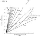
- the reference numeral 500 indicates a graph showing several curves of Yaw Rates for an example vehicle of specific wheelbase L.
- the solid curves 502 are the Yaw Rates in degrees per second as a function of the front wheel angles for different speeds.
- the solid curve 502A labeled '5 mph' shows the yaw rate of the vehicle increasing from 0 to over 150 degrees per second as the wheel angle increases from 0 to 30 degrees.
- Curves 502B, 502C, 502D, 502E, 502F, and 502G illustrate the Yaw Rates in degrees per second as a function of the front wheel angles at speeds of 10, 15, 20, 30, 40, and 55 miles per hour (MPH), respectively.
- Intermediate curves as shown may illustrate the illustrate the Yaw Rates in degrees per second as a function of the front wheel angles at speeds of 25, 35, 45, and 50 MPH.
- These curves 502 may be considered theoretical or calculated, and may not account for real-world physical phenomena related to servo deflection, tire slip, and the like. For example, as the speed increases, the steering servo is typically unable to hold the front wheels at the commanded angle. Additionally, for example, there is typically more tire slippage in a faster turn, widening the turn (increasing the turning radius) as the speed increases.
- a specific Yaw Rate may correspond to a specific curvature.
- the curvature may be 0 to 1.5 (1/m) or a turning radius from Infinity to approximately 0.67 m (2.2 feet). Since curvature is Yaw Rate / Speed, the curvature lines vs. wheel angle for every speed are the same for a specific car.
- a commanded yaw rate may be selected that corresponds to a slow speed and tends to ensure that all steering states can be met at any speed.
- This selection is shown in Figure 5 , Yaw Rates ( ⁇ ) as the dotted-line curve 504 labeled "User Commanded Rate".
- the X-axis is the steering wheel angle (for a steering wheel that travels between -30 degrees (left, counterclockwise) and +30 degrees (right, clockwise) where straight is 0 (zero) degrees) and the Y-axis is the corresponding commanded Yaw Rate.
- the user's commanded yaw rate is 127degrees per second.
- the commanded rate curve may be an exponential function of the user's input and may fall between the 5 and 10 mph lines for a 1/10th scale vehicle.
- the dashed-line curve 506 labeled "Roll-Over Curve” in the graph corresponds to the roll over yaw rate for a specific front wheel angle, and is only an estimate. However, it may be important that the user can command steering over and beyond the yaw rate that rolls the vehicle over. This may allow the user to get full steering capability at slower speeds.
- the roll-over yaw rate is shown here to give an indication of the range in which the vehicle may operate.
- a feedback control system may be utilized to steer the car and achieve the desired Yaw Rate. As shown in Figure 5 , if the car is moving too slowly, the commanded yaw rate cannot be achieved. The system may be designed to saturate to full steer in this case.
- the "driver assist” method decreases the counter steer gain with the driver's steering input.
- the counter steer gain is 0 (zero) and the assist strategy may achieve full steer by not counter steering at all.
- the electronic steering stability system may achieve full steer by integrating the error and saturating the servo. The more the user steers in the direction of the turn the quicker the error integrates and the sooner the servo saturates. Even without a speed sensor, the driver may feel more connected to the model vehicle and the vehicle may be perceived to be "doing what it is told” rather than steering against the driver's command.
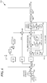
- FIG. 6 a block diagram illustrates an electronic steering stability system 600 having no speed sensor.
- the error integration may have to reach the servo's saturation point.
- Typical windup limits used to prevent excessive overshooting, may not work in situations where a low gain controller is needed.
- Integral windup refers to the situation in a PID feedback controller where a large change in setpoint occurs, such as positive change, for example, and the integral term accumulates a significant error during the rise (windup), thus overshooting and continuing to increase as this accumulated error is unwound or offset by errors in the opposite direction.
- the specific problem with integral windup is excess overshooting.
- Windup multiplied with the I gain may be less than the full steering command.
- a well-known anti-windup mechanism may be utilized in this instance.
- iVal When the integral term, exceeds the servo's maximum output, a retarding value may be fed back into the integrator.
- the User Steering Input may be provided to a Yaw Rate Command Map 602, which may operate to determine a particular Yaw Rate from the User Steering Input.
- User input u may be provided from Yaw Rate Command Map 602 to a first adder 604 to produce an "ERROR" signal.
- the "ERROR" signal may be provided to integral function I and to proportional function P.
- the output of integral function I may be subject to further processing, and may then be combined with the output of the proportional function P to produce a Servo Command.
- the Servo Command may be processed through a Servo Limiter 606 and thereafter be provided to Servo 406 for steering car, or ground model vehicle 200, through a turn.
- the differential function D may be subject to further processing, and may then be combined at adder 608 with the output of the proportional function P, the result of which may be provided to adder 610.
- the differential, proportional, and integral terms dVal, pVal, and iVal, respectively, may thereby be combined and may be provided from an output of adder 610 to an input of Servo Limiter 606 for steering the car, or ground model vehicle 200 as described above.
- the output of the integral function I may be subject to further processing.
- one mode of further processing may be through an Error Integration circuit 612.
- one mode of further processing may be through an Anti-Windup circuit 614.
- the Error Integrator circuit 612 may receive and integral function input at adder 616, which may be provided as the term iVal to an input of adder 610.
- the iVal signal may be fed back to multiplier 618 for further processing with the reciprocal of a "z" term, the output of which may be provided to multiplier 620 for further processing with leak factor ⁇
- a feedback signal representing Error Integration may be provided to an input of adder 616 for correction of errors in the integral term iVal.
- the Anti-Windup circuit 614 may combine the input to Servo Limiter 606 with the output of Servo Limiter 606 at adder 622, the output of which may be provided to multiplier 624 for further processing with the reciprocal of the "z" term.
- the output of multiplier 624 may be provided to multiplier 626 for further processing with the reciprocal of a "T t " term.
- the output of multiplier 626 may be provided to an input of adder 628 for corrections to the iVal term.
- the Anti-Windup circuit 614 may function to minimize or reduce excessive overshoot of the electronic steering stabilizing system, may create a smoothness in the response of the steering of the ground model vehicle 200 and may contribute to the proper "feel" or responsiveness of the ground model vehicle 200 to the input of the RC Driver.
- the steering may have "memory" when running slalom courses.
- Memory steer is the term used to describe a vehicle that continues to pull to the left or right after completing a turn in that same direction. This condition may develop when running courses with constant turns, such as slalom courses, for example.
- the integrator is made "leaky".
- a leaky integrator equation is a specific differential equation, used to describe a component or system that takes the integral of an input, but gradually leaks a small amount of input over time. A certain amount of error may accumulate in the integral term when the RC Driver commands a harder or tighter turn than the ground model vehicle can respond to.
- the integrator is made to leak so that this error is diminished or "leaks away” and becomes no longer relevant in the calculations.
- the leaking factor is represented as ⁇ (alpha) 620 in Fig. 6 . This integrator may leak when ⁇ (alpha) is less than 1.
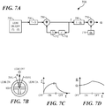
- a Leaky Integrator Scheduler 700 as shown in Figure 7A is a driven difference system that may be used to produce the ⁇ (alpha) value.
- the use of the Leaky Integrator Scheduler 700 may create a smoothness in the response of the steering of the ground model vehicle 200 and may contribute to the proper "feel" or responsiveness of the ground model vehicle 200 to the input of the RC Driver.
- a Leak On/Off detector 702 may determine whether the leak of the integrator may be turned off or on. Referring to Fig. 7B , when steering wheel 102 is turned to the right or to the left such that the steering wheel angle ⁇ exceeds a predetermined limit 701 in either direction, the leak of the integrator may be turned on, otherwise the leak of the integrator may be turned off. More particularly, the leak of the integrator may be turned off when the steering wheel angle ⁇ is 0 (zero), An On/Off signal may be provided to multiplier 704 where the On/Off signal is multiplied by 1-G where G may be a constant that determines how fast an " f " term rises to 1 or decays to 0.
- the "f” term may be used to slowly change alpha ( ⁇ ) as the driver moves in and out of the leak off and leak on steering angles.
- the output of multiplier 704 may be provided to an input of adder 706 where it may be summed with output from a feedback loop which may include at least the functions of multipliers 710 and 712.
- the output of adder 706 may be the " f " term provided to multiplier 708.
- the "f” term output of adder 706 may also be provided to multiplier 710 where it may be multiplied by the reciprocal of a gain value, "z" which may represent a certain time delay.
- Multiplier 712 may receive the output of multiplier 710 where it may be multiplied by the constant, G.
- the output of multiplier 712 may be provided as a feedback signal to adder 706 to correct the "f" term.
- the output of multiplier 708 may be combined with an ⁇ 0 term 714 at adder 716 to produce a current ⁇ (alpha) value.
- Fig. 7C illustrates turning on the leak for a period of time and then turning it off, and the effect on the f term.
- the f term may rise over time, and when the integrator leak is OFF, the f term may decrease over time. In an embodiment, the f term may decrease to zero.
- the Leaky Integrator Scheduler 700 may be used to smooth the systems response to the steering changes, and by virtue of the gradually rising or falling of the ⁇ (alpha) value, to make a gradual switch between integrator leak being ON and integrator leak being OFF, thereby contributing to smoothness of the steering stabilizing system response. This smoothness may contribute to the proper "feel" or responsiveness of the ground model vehicle 200 to the input of the RC Driver.
- the first control packet may define one method of communicating information between an RC Controller and an RC Receiver.
- the RC Controller may receive user commands, steering and throttle, for example, and communicate them to the receiver over a first control packet.
- the user commands of this first method may be combined with the configured properties of each associated RC Controller channel.
- Such properties may include trim, subtrim and endpoints, for example.
- the configured properties may be combined with the user commands to produce a single value representing the channel control value.
- the channel control value for steering may be a combination of the user commanded value, the trim, the subtrim and the endpoints.
- the channel control value for steering may be communicated to the RC receiver as Channel 1 Servo Control Value as shown in Figure 8 , for example.
- the RC receiver may then translate the control value into an output for the steering servo, in this example.
- the RC receiver may not be able to distinguish between the user command and the configured properties.
- a second control packet is shown as used by a second communication method.
- This second control packet has been reconfigured to communicate additional information as compared to the first control packet of the first communication method.
- additional information such as servo reversing (SR), Trim settings, button states (Set Button and Menu Button, for example), and knob positions may be included in the second control packet.
- SR servo reversing
- Trim settings Trim settings
- button states Set Button and Menu Button, for example
- knob positions may be included in the second control packet.
- a third control packet as shown in Figure 9B , may be used in this second communication method.
- the third control packet may communicate information corresponding to the endpoint settings for a control channel, such as the steering and throttle endpoints, for example. Using this second communication method, the properties of each channel may not need to be combined with the user command.
- the RC receiver may be able to distinguish between the user command and the configured properties.
- This second communication method may enable the electronic steering stability system 600 previously described to operate as intended without requiring the user to undergo lengthy calibration procedures each time the user may change the trim value associated with an operation channel, for example.
- the additional information may be stored in a memory of the RC receiver.
- the RC receiver may then use this additional information to result in an improved operation of the electronic steering stability system.
- the user command for steering may be used as the Reference Input, the Setpoint, for a Feedback Control Loop 1000.
- the Reference Input may be initially applied to one input of an adder 1002.
- the adder 1002 may produce an actuating signal 1004 that may be applied to an input of a controller 1006.
- the controller 1006 may produce a manipulated variable 1008 that may be depend upon multiple inputs representing multiple conditions.
- the manipulated variable 1008 may be provided to a "Process" 1010.
- the Process 1010 may be a steering process for a ground model vehicle.
- the configured channel properties may be contained as properties of the Plant 1010.
- the Process 1010 may respond to a disturbance 1018 in the conditions of the vehicle and produce a controlled variable output 1012.
- the controlled variable output 1012 may be provided to a control device such as a servo, but may also be provided to a feedback system 1014.
- the feedback system may process the controlled variable output 1012 and provide a feedback signal 1016 to a second input of adder 1002. This may enable the Feedback Control Loop 1000 to more accurately command the vehicle to track the user command for steering.
- a flow chart illustrates a process 1100 for determining whether to activate the integrator leak or not.
- the process may detect the steering wheel angle ⁇ and may calculate a steering angle ⁇ .
- the process may determine whether the steering wheel angle ⁇ is beyond predetermined limits. If the steering wheel angle ⁇ is beyond predetermined limits, in step 1106 the process may activate the integrator leak. If the steering wheel angle ⁇ is within the predetermined limits, in step 1108 the process may deactivate the integrator leak. The process may then return to step 1102 to detect steering wheel angle. As the steering wheel may be turned frequently in certain situations, such as maneuvering the vehicle around obstacles, the process 1100 may be continuously repeated, and may be repeated quite rapidly.
Landscapes
- Engineering & Computer Science (AREA)
- Physics & Mathematics (AREA)
- Computer Networks & Wireless Communication (AREA)
- General Physics & Mathematics (AREA)
- Chemical & Material Sciences (AREA)
- Combustion & Propulsion (AREA)
- Transportation (AREA)
- Mechanical Engineering (AREA)
- Radar, Positioning & Navigation (AREA)
- Aviation & Aerospace Engineering (AREA)
- Remote Sensing (AREA)
- Automation & Control Theory (AREA)
- Mathematical Physics (AREA)
- Steering Control In Accordance With Driving Conditions (AREA)
Description
- The present invention relates to model vehicles and, more particularly, to an electronic system to stabilize steering of the model vehicle.
- For a Radio Controlled (RC) Model Vehicle, the Driver controls the vehicle remotely. The RC Driver can only detect the vehicle's motion visually. The RC Driver cannot feel the vehicle's disturbances such as hitting a raised area of earth. The time constants for scaled vehicles are much smaller than the time constants for full sized vehicles. The smaller vehicle responds to disturbances and steering inputs much faster than full sized vehicle.
- Electronic steering stability may aid the RC Driver by stabilizing the steering. When steering stability is on, the Driver can focus on larger steering inputs while the electronic steering stability system responds to disturbances around the Driver's steering inputs.
- Some systems treat the steering stability as a "driver assist". These controllers add a limited adjustment to the driver's commanded steering input. This assist drives the yaw rate to zero. For forward travel (where the driver commands 0 (zero) steering angle), adjusting for a zero yaw rate may be exactly what the driver wishes. However, when the Driver commands a turn, the Driver may not want a zero yaw rate. For example, an assist system adds counter steer against the driver's wishes. Embodiments of these types of systems typically include well-known gain scheduling strategies to minimize the counter steer as the driver's steering input increases or throttle input decreases. These systems do not provide the right "feel" as the car seems to be disconnected from the driver.
- Using said "driver assist" strategy leads to a different issue. In the zero steering input case, the cars heading should be constant. To hold the heading in the face of slight steering bias from driving transverse to a grade or slightly off steering trim, this requires correction based on the integration of the yaw error rate. One such system defines a "heading region" that introduces correction on the integrated yaw error rate when the driver inputs zero steering. This function cannot be active when the driver inputs non-zero steering as the error will integrate, and the assist would hit its limits or, if the limits are wide enough and the gain large enough, this function would counter-steer the car straight. This discontinuity is another example of disconnecting the driver's input from the vehicle - a small input difference on the steering wheel, and the vehicle behaves differently. Therefore the car seems to be disconnected from the driver and the system fails to provide the proper feel.
US 6241574 discloses a device for influencing the handling characteristics of remote-controlled model cars or model ships, comprising a first input terminal for a first control signal which represents a first command variable which can be specified by a person who controls the vehicle, a sensor means which outputs a second control signal which represents a disturbance variable correlated with the rotational velocity or the lateral acceleration of the model vehicle, and a processing means which is connected with the first input terminal for receiving the first control signal and which has a second input terminal for receiving the second control signal, and which generates a first output signal which represents a first manipulated variable being a function of the first command variable and of the disturbance variable, with the first manipulated variable generated by the processing means being the command variable which as a function of the disturbance variable is limited or modified to a predeterminable degree. - An electronic system for stabilizing steering of an RC model vehicle according to
claim 1, and a method for stabilizing steering of an RC model vehicle according to claim 6. - For a more complete understanding of the present invention and the advantages thereof, reference is now made to the following Detailed Description taken in conjunction with the accompanying drawings, in which:
-
FIGURE 1 illustrates a standard RC Controller used for surface model vehicles, such as model cars and model trucks, for example; -
FIGURE 2 illustrates the use of a Radio Control (RC) steering control 'knob (aka "steering wheel"); -
FIGURE 3 illustrates a steering angle as applied to a land-based, surface model vehicle; -
FIGURE 4 is a block diagram of a curvature controller; -
FIGURE 5 is a graph illustrating yaw rates compared with wheel angle; -
FIGURE 6 is block diagram illustrating a control system with no speed sensor; -
FIGURE 7A is a block diagram illustrating a leaky integrator scheduler; -
FIGURE 7B is a pictorial representation of steering wheel angle; -
FIGURE 7C is a graph showing the change in a variable over time; -
FIGURE 7D is a graph showing the change in a variable over time; -
FIGURE 8 is a table defining a first control packet between an RC Controller and an RC receiver as used by a first communication method; -
FIGURE 9A is a table defining a second control packet between an RC Controller and an RC receiver as used by a second communication method; -
FIGURE 9B is a table defining a third control packet between an RC Controller and an RC receiver as used by a second communication method; -
FIGURE 10 is a block diagram depicting operation of a feedback control loop; and -
FIGURE 11 is a flowchart illustrating a process. - Turning now to
Figure 1 , thereference numeral 100 generally indicates a standard RC Controller used for surface model vehicles, such as model cars and model trucks, for example. The RC Controller may have a least asteering wheel 102 and athrottle trigger 104. The RC Controller may also have ahousing 106, which may include a hand-grip handle 108 for grasping the RC Controller. The Driver may use the standardsurface RC Controller 100, as shown inFigure 1 , to control avehicle 200. The RC Driver may command steering input using thesteering wheel 102. The RC Driver may command speed and forward/reverse direction using thethrottle trigger 104. The RC Driver may thereby produce at least a steering command and a throttle command. The RC Controller 100 may transmit the RC Driver's steering and throttle commands to an RC Receiver in themodel vehicle 200 being controlled. With no electronic steering stability, the RC Receiver 202 may simply command a Steering Servo to a corresponding angle to steer the front wheels of thevehicle 200. This is illustrated inFigure 2 with respect to theRC steering wheel 102 showing a steering wheel angle θ. As shown inFigure 3 , a land-based,ground model vehicle 200 is illustrated as performing a turn. Theground model vehicle 200 may comprise non-steerablewheels 206 and may also comprisesteerable wheels 208. Thenon-steerable wheels 206 and thesteerable wheels 208 may be spaced apart by a wheelbase distance L. Theground model vehicle 200 may be travelling in a forward direction at a speed v. In response to an RC Driver's commands, theground model vehicle 200 may steer thesteerable wheels 208 at a steering angle ϕ and execute a turn having a radius r. With electronic steering stability, the RC Receiver 202 may execute a control system to compensate for disturbances to theground model vehicle 200, such as hitting a raised area of earth, for example. The RC Driver, operating theground model vehicle 200 remotely typically cannot feel such disturbances as one would inside a full-size vehicle and may therefore be unable to compensate for such disturbances. The time constants for scaled vehicles are much smaller than the time constants for full sized vehicles. The smaller vehicle responds to disturbances and steering inputs much faster than full sized vehicle. An Electronic Steering Stability (ESS)system 400 may receive inputs from sensors detecting such disturbances, calculate compensating command values, and may command the Steering Servo with the calculated command to control, in the example shown, the Yaw rate to the Driver's commanded rate. - The Electronic Steering Stability (ESS)
system 400 may be a feedback control system that uses 6-axis MEMS devices (3 axis of rate Gyros and 3 axis of Accelerometers) and, optionally, a speed sensor. The control system may use common control methodologies such as Proportional-Integral-Differential (PID) error feedback. The primary controlled output may be Yaw rate or, with a speed sensor, turning curvature. The electronic steering stability system may use the steering servo command as the control variable. - The Electronic Steering Stability (ESS) system may be a standard control system that drives the error or difference between the user input (u) and the feedback measurement (y) to zero. This is in contrast to the driver assist strategy, which drives the vehicle's yaw rate to 0 (zero) by counter steering, and typically decreases the assist amount inversely with steering input or vehicle speed, using gain scheduling.
- In the case of commanded 0 (zero) curvature (infinite turning radius), a speed sensor, and a PID controller, the result may be a heading-hold gyro, which maintains the current direction of a vehicle, together with linear gain scheduling with inverse of speed. Without a speed sensor, the result may be the functional equivalent of a simple heading-hold gyro.
- In the case in which a speed sensor is provided, the user may command a certain curvature (1/r) turn to the right, or to the left. The control system may calculate the difference between commanded curvature and the measured curvature (Yaw Rate / speed). If the difference is positive, the system may command the steering servo to angle the front wheels more in the direction of the turn, to increase the yaw rate. If the difference is negative, the system may command less front wheel angle, to decrease the yaw rate.
- Turning now to
Figure 4 , one aspect of the Electronic Steering Stability (ESS) system 400may be controlling curvature in a remote control car. This may be accomplished with the inclusion of aspeed sensor 410. Thespeed sensor 410 may be an actual sensor such as an optical flow sensor. Thespeed sensor 410 may be a fusion or combination of several sensors. An example of this is an extended Kalman Filter fusing accelerometers, gyros, GPS, and the like. to estimate the vehicle's velocity v and the user steering wheel input u directing curvature. - As shown in
Fig. 4 , theRC Controller 100 may generate user input u by turningsteering wheel 102. User input u may be fed to a first input of anadder 402. Theadder 402 may generate an error value, which may be fed intoPID Controller 404. The output of thePID Controller 404 may be fed into an input ofsteering servo 406, to command steering angle ϕ as shown inFig. 2 . Thesteering servo 406 is well-understood to be a part of the car, orground model vehicle 200. Together with the THROTTLE input commanding the speed v ofground model vehicle 200, and actuation ofsteering servo 406 responding to user input u and commanding a steering angle ϕ, the car, orground model vehicle 200, may execute a TURN. - The TURN may be detected by
Gyros 408, which may be 6-axis MEMS devices having three axes of rate gyros and three axes of accelerometers. Aspeed sensor 410 may also be provided as described above. Output values representing three axes of rate gyro and three axes of accelerometers may be fed into acurvature estimator 412. The three axes of accelerometers may be used to determine the vector linear acceleration of the vehicle. Thecurvature estimator 412 may calculate a measured Yaw rate using theGyros 408 information and vector acceleration of theground model vehicle 200, as detected byGyros 408. Thecurvature estimator 412 may calculate a measured curvature based upon variations in the attitude Yaw rate and vector acceleration of the car, orground model vehicle 200, as detected bygyros 408, and the speed of the car, orground model vehicle 200, as detected byspeed sensor 410.. Curvature may be defined as the reciprocal of the radius r of the turn, or 1/r, and may be estimated by one or more of: Yaw rate and a model of the car at an assumed speed; Gyro rates and linear acceleration using something like a Kalman filter; and Gyro rates and a speed sensor. Thecurvature estimator 412 may calculate a measured curvature based upon the values of steering angle ϕ, the speed v of the car, orground model vehicle 200, and the distance of wheelbase L, as shown inFig. 2 . - The
curvature estimator 412 may provide a feedback output value y to a second input ofadder 402. Theadder 402 may generate an error value based upon user input u and feedback output value y, which may be fed intoPID Controller 404 to further control steering of theground model vehicle 200. - A speed estimate with sufficient accuracy may require more sensors than a 6-axis MEMS sensor. These additional sensors may be expensive and require packaging to ensure crash survivability and water resistance.
- Another aspect of the Electronic Steering Stability (ESS) system may be a heading hold system that brings in several aspects of curvature control without requiring a speed sensor. Additionally, the system may include a scheduled leaky integrator coefficient to improve the driver's perceived steering response.
- Turning now to
Figure 5 , thereference numeral 500 indicates a graph showing several curves of Yaw Rates for an example vehicle of specific wheelbase L. Thesolid curves 502 are the Yaw Rates in degrees per second as a function of the front wheel angles for different speeds. For example, thesolid curve 502A labeled '5 mph' shows the yaw rate of the vehicle increasing from 0 to over 150 degrees per second as the wheel angle increases from 0 to 30 degrees.Curves curves 502 may be considered theoretical or calculated, and may not account for real-world physical phenomena related to servo deflection, tire slip, and the like. For example, as the speed increases, the steering servo is typically unable to hold the front wheels at the commanded angle. Additionally, for example, there is typically more tire slippage in a faster turn, widening the turn (increasing the turning radius) as the speed increases. - If the car speed is fixed at a specific value, in this
case 5 mph, a specific Yaw Rate may correspond to a specific curvature. In this example, the curvature may be 0 to 1.5 (1/m) or a turning radius from Infinity to approximately 0.67 m (2.2 feet). Since curvature is Yaw Rate / Speed, the curvature lines vs. wheel angle for every speed are the same for a specific car. - To provide a response without a speed sensor, a commanded yaw rate may be selected that corresponds to a slow speed and tends to ensure that all steering states can be met at any speed. This selection is shown in
Figure 5 , Yaw Rates (ψ) as the dotted-line curve 504 labeled "User Commanded Rate". In this case, the X-axis is the steering wheel angle (for a steering wheel that travels between -30 degrees (left, counterclockwise) and +30 degrees (right, clockwise) where straight is 0 (zero) degrees) and the Y-axis is the corresponding commanded Yaw Rate. For example, if the user turns the steering wheel right (clockwise) by 15 degrees, the user's commanded yaw rate is 127degrees per second. The commanded rate curve may be an exponential function of the user's input and may fall between the 5 and 10 mph lines for a 1/10th scale vehicle. - The dashed-
line curve 506 labeled "Roll-Over Curve" in the graph corresponds to the roll over yaw rate for a specific front wheel angle, and is only an estimate. However, it may be important that the user can command steering over and beyond the yaw rate that rolls the vehicle over. This may allow the user to get full steering capability at slower speeds. The roll-over yaw rate is shown here to give an indication of the range in which the vehicle may operate. - Given the user commanded Yaw Rate and the measured Yaw Rate, a feedback control system may be utilized to steer the car and achieve the desired Yaw Rate. As shown in
Figure 5 , if the car is moving too slowly, the commanded yaw rate cannot be achieved. The system may be designed to saturate to full steer in this case. - Contrasting with the typical method of decreasing gain scheduling applied to the steering adjustment, the "driver assist" method decreases the counter steer gain with the driver's steering input. When the driver inputs full steer, the counter steer gain is 0 (zero) and the assist strategy may achieve full steer by not counter steering at all.
- The electronic steering stability system may achieve full steer by integrating the error and saturating the servo. The more the user steers in the direction of the turn the quicker the error integrates and the sooner the servo saturates. Even without a speed sensor, the driver may feel more connected to the model vehicle and the vehicle may be perceived to be "doing what it is told" rather than steering against the driver's command.
- There are some aspects of the electronic steering stability system that may require special attention. Turning now to
Figure 6 , a block diagram illustrates an electronicsteering stability system 600 having no speed sensor. To achieve full steering in all situations the error integration may have to reach the servo's saturation point. Typical windup limits, used to prevent excessive overshooting, may not work in situations where a low gain controller is needed. Integral windup refers to the situation in a PID feedback controller where a large change in setpoint occurs, such as positive change, for example, and the integral term accumulates a significant error during the rise (windup), thus overshooting and continuing to increase as this accumulated error is unwound or offset by errors in the opposite direction. The specific problem with integral windup is excess overshooting. (Windup multiplied with the I gain may be less than the full steering command). A well-known anti-windup mechanism may be utilized in this instance. When the integral term, iVal, exceeds the servo's maximum output, a retarding value may be fed back into the integrator. - As shown in
Fig. 6 , the User Steering Input may be provided to a YawRate Command Map 602, which may operate to determine a particular Yaw Rate from the User Steering Input. User input u may be provided from YawRate Command Map 602 to afirst adder 604 to produce an "ERROR" signal. The "ERROR" signal may be provided to integral function I and to proportional function P. The output of integral function I may be subject to further processing, and may then be combined with the output of the proportional function P to produce a Servo Command. The Servo Command may be processed through aServo Limiter 606 and thereafter be provided toServo 406 for steering car, orground model vehicle 200, through a turn. Feedback from the turn may be provided back toadder 604, and to the differential function D. The output of the differential function D may be subject to further processing, and may then be combined atadder 608 with the output of the proportional function P, the result of which may be provided to adder 610. The differential, proportional, and integral terms dVal, pVal, and iVal, respectively, may thereby be combined and may be provided from an output ofadder 610 to an input ofServo Limiter 606 for steering the car, orground model vehicle 200 as described above. - The output of the integral function I may be subject to further processing. In an embodiment, one mode of further processing may be through an
Error Integration circuit 612. In an embodiment, one mode of further processing may be through anAnti-Windup circuit 614. TheError Integrator circuit 612 may receive and integral function input atadder 616, which may be provided as the term iVal to an input ofadder 610. The iVal signal may be fed back tomultiplier 618 for further processing with the reciprocal of a "z" term, the output of which may be provided tomultiplier 620 for further processing with leak factor α - (alpha). A feedback signal representing Error Integration may be provided to an input of
adder 616 for correction of errors in the integral term iVal. TheAnti-Windup circuit 614 may combine the input toServo Limiter 606 with the output ofServo Limiter 606 atadder 622, the output of which may be provided tomultiplier 624 for further processing with the reciprocal of the "z" term. The output ofmultiplier 624 may be provided tomultiplier 626 for further processing with the reciprocal of a "Tt" term. The output ofmultiplier 626 may be provided to an input ofadder 628 for corrections to the iVal term. TheAnti-Windup circuit 614 may function to minimize or reduce excessive overshoot of the electronic steering stabilizing system, may create a smoothness in the response of the steering of theground model vehicle 200 and may contribute to the proper "feel" or responsiveness of theground model vehicle 200 to the input of the RC Driver. - With just the anti-windup facility, the steering may have "memory" when running slalom courses. Memory steer is the term used to describe a vehicle that continues to pull to the left or right after completing a turn in that same direction. This condition may develop when running courses with constant turns, such as slalom courses, for example. To counter this effect to a desired degree (partially or fully), the integrator is made "leaky". In mathematics, a leaky integrator equation is a specific differential equation, used to describe a component or system that takes the integral of an input, but gradually leaks a small amount of input over time. A certain amount of error may accumulate in the integral term when the RC Driver commands a harder or tighter turn than the ground model vehicle can respond to. In situations such as these, the integrator is made to leak so that this error is diminished or "leaks away" and becomes no longer relevant in the calculations. The leaking factor is represented as α (alpha) 620 in
Fig. 6 . This integrator may leak when α (alpha) is less than 1. - When the model vehicle is commanded with a steering wheel angle of 0 (zero), the leak of the integrator may be turned off (α (alpha) may be set to 1). This may allow the ground model vehicle to overcome any bias in the steering. RC Drivers may like the response of the vehicle to feel smooth. A
Leaky Integrator Scheduler 700 as shown inFigure 7A is a driven difference system that may be used to produce the α (alpha) value. The use of theLeaky Integrator Scheduler 700 may create a smoothness in the response of the steering of theground model vehicle 200 and may contribute to the proper "feel" or responsiveness of theground model vehicle 200 to the input of the RC Driver. - As shown in
Fig. 7A , a Leak On/Off detector 702 may determine whether the leak of the integrator may be turned off or on. Referring toFig. 7B , when steeringwheel 102 is turned to the right or to the left such that the steering wheel angle θ exceeds a predetermined limit 701 in either direction, the leak of the integrator may be turned on, otherwise the leak of the integrator may be turned off. More particularly, the leak of the integrator may be turned off when the steering wheel angle θ is 0 (zero), An On/Off signal may be provided tomultiplier 704 where the On/Off signal is multiplied by 1-G where G may be a constant that determines how fast an "f" term rises to 1 or decays to 0. The "f" term may be used to slowly change alpha (α) as the driver moves in and out of the leak off and leak on steering angles. The output ofmultiplier 704 may be provided to an input ofadder 706 where it may be summed with output from a feedback loop which may include at least the functions ofmultipliers adder 706 may be the "f" term provided tomultiplier 708. The "f" term output ofadder 706 may also be provided tomultiplier 710 where it may be multiplied by the reciprocal of a gain value, "z" which may represent a certain time delay.Multiplier 712 may receive the output ofmultiplier 710 where it may be multiplied by the constant, G. The output ofmultiplier 712 may be provided as a feedback signal to adder 706 to correct the "f" term. The output ofmultiplier 708 may be combined with an α0 term 714 atadder 716 to produce a current α (alpha) value. The alpha (α) value of a leaky integrator may be expressed as follows:
- Referring now to
Fig. 7C and Fig. 7D, Fig 7C illustrates turning on the leak for a period of time and then turning it off, and the effect on the f term. When integrator leak is ON, the f term may rise over time, and when the integrator leak is OFF, the f term may decrease over time. In an embodiment, the f term may decrease to zero.Fig. 7D illustrates the resulting alpha (α) term over time. When the leak is turned on, alpha rises slowly from an initial value, α0, to 1, noting that at alpha=1, the integrator's leak is off. When the leak is turned off alpha falls slowly to α0, noting that when the integrator's leak is on, α < 1. In an embodiment, theLeaky Integrator Scheduler 700 may be used to smooth the systems response to the steering changes, and by virtue of the gradually rising or falling of the α (alpha) value, to make a gradual switch between integrator leak being ON and integrator leak being OFF, thereby contributing to smoothness of the steering stabilizing system response. This smoothness may contribute to the proper "feel" or responsiveness of theground model vehicle 200 to the input of the RC Driver. - Turning now to
Figure 8 , a first control packet is shown as used by a first communication method. The first control packet may define one method of communicating information between an RC Controller and an RC Receiver. In a first method, the RC Controller may receive user commands, steering and throttle, for example, and communicate them to the receiver over a first control packet. The user commands of this first method may be combined with the configured properties of each associated RC Controller channel. Such properties may include trim, subtrim and endpoints, for example. The configured properties may be combined with the user commands to produce a single value representing the channel control value. For example, the channel control value for steering may be a combination of the user commanded value, the trim, the subtrim and the endpoints. The channel control value for steering may be communicated to the RC receiver asChannel 1 Servo Control Value as shown inFigure 8 , for example. The RC receiver may then translate the control value into an output for the steering servo, in this example. By combining the properties of the channel with the user command into a single value, the RC receiver may not be able to distinguish between the user command and the configured properties. - Turning now to
Figure 9A , a second control packet is shown as used by a second communication method. This second control packet has been reconfigured to communicate additional information as compared to the first control packet of the first communication method. In this second communication method, additional information such as servo reversing (SR), Trim settings, button states (Set Button and Menu Button, for example), and knob positions may be included in the second control packet. Additionally, a third control packet, as shown inFigure 9B , may be used in this second communication method. The third control packet may communicate information corresponding to the endpoint settings for a control channel, such as the steering and throttle endpoints, for example. Using this second communication method, the properties of each channel may not need to be combined with the user command. Therefore, the RC receiver may be able to distinguish between the user command and the configured properties. This second communication method may enable the electronicsteering stability system 600 previously described to operate as intended without requiring the user to undergo lengthy calibration procedures each time the user may change the trim value associated with an operation channel, for example. - In the second communication method the additional information may be stored in a memory of the RC receiver. The RC receiver may then use this additional information to result in an improved operation of the electronic steering stability system. Referring now to
Figure 10 , the user command for steering may be used as the Reference Input, the Setpoint, for aFeedback Control Loop 1000. The Reference Input may be initially applied to one input of anadder 1002. Theadder 1002 may produce anactuating signal 1004 that may be applied to an input of acontroller 1006. Thecontroller 1006 may produce a manipulated variable 1008 that may be depend upon multiple inputs representing multiple conditions. The manipulated variable 1008 may be provided to a "Process" 1010. In an embodiment, theProcess 1010 may be a steering process for a ground model vehicle. The configured channel properties (trim and subtrim, for example) may be contained as properties of thePlant 1010. TheProcess 1010 may respond to adisturbance 1018 in the conditions of the vehicle and produce a controlledvariable output 1012. The controlledvariable output 1012 may be provided to a control device such as a servo, but may also be provided to afeedback system 1014. The feedback system may process the controlledvariable output 1012 and provide afeedback signal 1016 to a second input ofadder 1002. This may enable theFeedback Control Loop 1000 to more accurately command the vehicle to track the user command for steering. - Turning now to
Figure 11 , a flow chart illustrates aprocess 1100 for determining whether to activate the integrator leak or not. Atstep 1102, the process may detect the steering wheel angle θ and may calculate a steering angle ϕ. Atstep 1104, the process may determine whether the steering wheel angle θ is beyond predetermined limits. If the steering wheel angle θ is beyond predetermined limits, instep 1106 the process may activate the integrator leak. If the steering wheel angle θ is within the predetermined limits, instep 1108 the process may deactivate the integrator leak. The process may then return to step 1102 to detect steering wheel angle. As the steering wheel may be turned frequently in certain situations, such as maneuvering the vehicle around obstacles, theprocess 1100 may be continuously repeated, and may be repeated quite rapidly. - Having thus described the present invention by reference to certain of its exemplary embodiments, it is noted that the embodiments disclosed are illustrative rather than limiting in nature. The scope of the invention is defined by the appended claims.
Claims (7)
- An electronic system for stabilizing steering of an RC model vehicle (200) providing a curvature steering control of the RC model vehicle, the electronic system comprising:an input for receiving a user steering command corresponding to a commanded curvature;a gyroscopic sensing system (408) for sensing rotation rate and linear acceleration of the ground model vehicle; andan adder (402) for producing an error signal from the input and a feedback signal;a proportional-integral-differential PID controller (404), wherein the PID controller receives the error signal and produces an output signal;a steering servo (406) coupled to the PID controller for receiving the output signal, wherein the steering servo controls steering of the RC model vehicle;a feedback system comprising a curvature estimator (412) coupled to the gyroscopic sensing system for estimating at least one parameter of a turn;wherein the inverse of the output of the feedback system is applied to the adder to achieve the commanded curvature;characterized in that:
error integration is used to achieve full steering, including the application of a leaky integrator to minimize steering memory, wherein the leak factor is a time-based function of the steering input. - The system of Claim 1, further comprising a speed sensor (410) for sensing the speed of the RC model vehicle, wherein the speed sensor is coupled to the curvature estimator.
- The system of Claim 1, wherein the approximate curvature control of the RC model vehicle is determined.
- The system of Claim 1, wherein the control system provides curvature control of the RC model vehicle where the driver's input is the desired curvature and the electronic system controls the vehicle's steering to match the driver's commanded curvature.
- The system of Claim 1, wherein the electronic system functions as a heading-hold system when the user steering command is set to 0 steering, i.e. infinite curvature.
- A method for stabilizing steering of an RC model vehicle providing a curvature steering control of the RC model vehicle, the method comprising:generating a user input representing a commanded curvature of a turn;measuring parameters of the turn;calculating measured parameters of the turn; andproviding the calculated measured parameters as feedback representing the turn;comparing the user input to feedback representing a turn;generating an error signal representing a difference between the user input and the feedback;performing a proportional-integral-differential process upon the error signal;controlling a steering servo to a commanded position; andexecuting a turn in a model vehicle to achieve the commanded curvature;characterized in that:
error integration is used to achieve full steering, including the application of a leaky integrator to minimize steering memory wherein the leak factor is a time-based function of the steering input. - A method as claimed in claim 6, the method further comprising:receiving a user steering input;processing the user steering input to calculate a servo command for steering the RC Model vehicle;measuring parameters of an actual turn executed by the model vehicle;providing feedback indicative of the actual turn to the processing of the user steering input for modifying the servo command;calculating a servo command from the user steering input as modified by the feedback.
Applications Claiming Priority (2)
| Application Number | Priority Date | Filing Date | Title |
|---|---|---|---|
| US201562149514P | 2015-04-17 | 2015-04-17 | |
| PCT/US2016/028175 WO2016168854A1 (en) | 2015-04-17 | 2016-04-18 | Steering stabilizing apparatus for a model vehicle |
Publications (2)
| Publication Number | Publication Date |
|---|---|
| EP3283186A1 EP3283186A1 (en) | 2018-02-21 |
| EP3283186B1 true EP3283186B1 (en) | 2019-05-22 |
Family
ID=55854809
Family Applications (1)
| Application Number | Title | Priority Date | Filing Date |
|---|---|---|---|
| EP16718963.8A Active EP3283186B1 (en) | 2015-04-17 | 2016-04-18 | Steering stabilizing apparatus for a model vehicle |
Country Status (4)
| Country | Link |
|---|---|
| US (1) | US9975056B2 (en) |
| EP (1) | EP3283186B1 (en) |
| CN (1) | CN107690350B (en) |
| WO (1) | WO2016168854A1 (en) |
Families Citing this family (18)
| Publication number | Priority date | Publication date | Assignee | Title |
|---|---|---|---|---|
| US9320977B2 (en) * | 2013-10-02 | 2016-04-26 | Horizon Hobby, LLC | Dynamic stabilization system and methods for a RC vehicle |
| JP6369399B2 (en) * | 2015-06-26 | 2018-08-08 | 株式会社デンソー | Sensor output correction device |
| CN106926894A (en) * | 2015-12-31 | 2017-07-07 | 罗伯特·博世有限公司 | Steering wheel rotation information determining device and steering wheel rotation information determine method |
| WO2018075815A1 (en) * | 2016-10-19 | 2018-04-26 | Traxxas Lp | Accessory connection system, method and apparatus for a model vehicle |
| JP6863011B2 (en) | 2017-03-31 | 2021-04-21 | トヨタ自動車株式会社 | Steering control device |
| DE102017121952A1 (en) * | 2017-09-21 | 2019-03-21 | Trw Automotive Gmbh | Method for detecting disturbances in a steering system and steering system for a motor vehicle |
| EP3540872A1 (en) | 2018-03-15 | 2019-09-18 | Wöhner Besitz GmbH | A hybrid busbar for a busbar system |
| US10773748B2 (en) * | 2018-05-17 | 2020-09-15 | Steering Solutions Ip Holding Corporation | Compensator anti-windup for motion control systems |
| US10848093B2 (en) * | 2018-08-30 | 2020-11-24 | Steering Solutions Ip Holding Corporation | Electrical power steering with two controllers using uniform steering angle control |
| FR3093687B1 (en) * | 2019-03-13 | 2022-07-29 | Renault Sas | Process for autonomously controlling the mobility of a device |
| DE102019205922B4 (en) * | 2019-04-25 | 2023-11-30 | Volkswagen Aktiengesellschaft | Determination of curve direction for a vehicle |
| EP3875350B1 (en) * | 2020-03-06 | 2024-08-07 | Zenuity AB | Method and arrangement for ensuring road tracking up to a predefined lateral acceleration limit using a pid controller in a vehicle |
| CN114248831B (en) * | 2020-09-25 | 2024-06-07 | 本田技研工业株式会社 | Electric power steering apparatus |
| JP7790878B2 (en) * | 2021-05-31 | 2025-12-23 | 双葉電子工業株式会社 | Model car steering mechanism |
| US12544683B2 (en) * | 2021-06-15 | 2026-02-10 | Traxxas, L.P. | Drag racing stability management for a model vehicle |
| CN114013505A (en) * | 2021-11-12 | 2022-02-08 | 合众新能源汽车有限公司 | Electric vehicle, steering control method and device for electric vehicle, and storage medium |
| DE202022102077U1 (en) * | 2022-04-19 | 2023-07-21 | Sturmkind Gmbh | Toy vehicle with rotation rate sensor |
| WO2024025966A2 (en) * | 2022-07-26 | 2024-02-01 | Anamnesis Corporation | Combination vehicle system and/or method |
Family Cites Families (60)
| Publication number | Priority date | Publication date | Assignee | Title |
|---|---|---|---|---|
| JPH062190B2 (en) * | 1987-04-24 | 1994-01-12 | 双葉電子工業株式会社 | Radio transmitter |
| GB8913212D0 (en) | 1989-06-08 | 1989-07-26 | Lotus Group Plc | A wheeled vehicle steering system |
| EP0663333B1 (en) * | 1994-01-14 | 1998-12-23 | Matsushita Electric Industrial Co., Ltd. | Steering angle control apparatus |
| US5762554A (en) * | 1996-08-23 | 1998-06-09 | Penta Blesses Enterprises Limited | Closed-loop steering control mechanism |
| WO1998014253A1 (en) * | 1996-10-02 | 1998-04-09 | Gm Racing Modellsportvertrieb Gmbh | Device to influence the driving performance of a remote-controlled model vehicle |
| JPH1178826A (en) * | 1997-09-10 | 1999-03-23 | Honda Motor Co Ltd | Driving operation support control device |
| JP3201337B2 (en) * | 1998-03-27 | 2001-08-20 | 双葉電子工業株式会社 | Mobile control device |
| US20030043053A1 (en) * | 2001-08-31 | 2003-03-06 | Schuckel Michael L. | Spread spectrum radio control system for models |
| JP2005510398A (en) | 2001-11-29 | 2005-04-21 | ダイムラークライスラー・アクチェンゲゼルシャフト | Device for evaluating and / or influencing vehicle operating variables and / or vehicle operating characteristics |
| JP2006020652A (en) * | 2001-12-17 | 2006-01-26 | Satoru Kojima | Roll angle controlling device for radio controlled model, and radio controlled model bicycle |
| JP2004050978A (en) * | 2002-07-19 | 2004-02-19 | Honda Motor Co Ltd | Tire linear region determining device, tire linear region determining program, vehicle driving operation device, and steering control method for steer-by-wire vehicle |
| AU2002354225A1 (en) | 2002-12-18 | 2004-07-09 | Satoru Kojima | Roll angle controller for remote-controlled traveling body, and roll angle controller for remote-controlled motor cycle |
| US20050003735A1 (en) * | 2003-07-01 | 2005-01-06 | Radioshack Corporation | Transmitter adaptable for left-handed or right-handed use |
| US6821184B1 (en) * | 2003-08-04 | 2004-11-23 | Garry Yeung | Steering alignment system for a toy car |
| US8154227B1 (en) | 2003-11-26 | 2012-04-10 | Liontech Trains Llc | Model train control system |
| JP4231416B2 (en) * | 2004-01-07 | 2009-02-25 | トヨタ自動車株式会社 | Vehicle steering device |
| JP4251100B2 (en) | 2004-03-25 | 2009-04-08 | 三菱ふそうトラック・バス株式会社 | Rollover suppression control device for vehicle |
| JP4211684B2 (en) * | 2004-05-31 | 2009-01-21 | トヨタ自動車株式会社 | Driving assistance device |
| JP4526342B2 (en) | 2004-09-27 | 2010-08-18 | 株式会社アドヴィックス | 4-wheel drive vehicle motion control device |
| US7740516B2 (en) | 2005-02-24 | 2010-06-22 | Castle Creations, Inc | Electronic speed control programming |
| US20070035412A1 (en) | 2005-08-12 | 2007-02-15 | Dvorak Joseph L | Application of profiles in a wireless device to control a remote control apparatus |
| US20080026671A1 (en) | 2005-10-21 | 2008-01-31 | Motorola, Inc. | Method and system for limiting controlled characteristics of a remotely controlled device |
| ES2331016T3 (en) | 2005-11-30 | 2009-12-18 | Svend Egenfeldt | REMOTE CONTROL SYSTEM. |
| US20130231814A1 (en) | 2006-03-06 | 2013-09-05 | Sterraclimb Llc | Stair-climbing surveillance vehicle |
| US7835832B2 (en) * | 2007-01-05 | 2010-11-16 | Hemisphere Gps Llc | Vehicle control system |
| US8160816B2 (en) | 2007-08-27 | 2012-04-17 | Honda Motor Co., Ltd. | Vehicular behavior determination device and vehicular behavior determination method |
| US8195366B2 (en) | 2007-09-13 | 2012-06-05 | The Raymond Corporation | Control system for a pallet truck |
| US8086376B2 (en) | 2007-10-10 | 2011-12-27 | Ford Global Technologies Llc | Vehicle rollover prediction with occupant restraint system activation |
| JP4712020B2 (en) * | 2007-11-21 | 2011-06-29 | 近藤科学株式会社 | Radio controlled model car capable of stable running |
| CN102362233B (en) | 2009-01-26 | 2013-11-06 | 爱考斯研究株式会社 | vehicle |
| EP2437586B9 (en) | 2009-06-02 | 2019-02-13 | Topcon Precision Agriculture Pty Ltd | Vehicle guidance system |
| US8527113B2 (en) | 2009-08-07 | 2013-09-03 | Irobot Corporation | Remote vehicle |
| GB2472786A (en) * | 2009-08-17 | 2011-02-23 | Alien Technology Ltd | Steering arrangement for toy vehicle |
| US9542833B2 (en) | 2009-09-10 | 2017-01-10 | Traxxas Lp | Automatic determination of radio control unit configuration parameter settings |
| WO2011032208A1 (en) | 2009-09-15 | 2011-03-24 | The University Of Sydney | A system and method for autonomous navigation of a tracked or skid-steer vehicle |
| CN102686476B (en) | 2009-12-25 | 2014-10-08 | 雅马哈发动机株式会社 | Driver characteristic judging device and saddled vehicle including said driver characteristic judging device |
| US8457830B2 (en) | 2010-03-22 | 2013-06-04 | John R. Goulding | In-line legged robot vehicle and method for operating |
| AU2014216022B2 (en) * | 2010-07-19 | 2015-11-05 | China Industries Limited | Racing vehicle game |
| GB2482119B (en) * | 2010-07-19 | 2013-01-23 | China Ind Ltd | Racing vehicle game |
| US9205869B2 (en) | 2010-08-16 | 2015-12-08 | Honda Motor Co., Ltd. | System and method for determining a steering angle for a vehicle and system and method for controlling a vehicle based on same |
| JP5429126B2 (en) | 2010-10-01 | 2014-02-26 | トヨタ自動車株式会社 | Driving support apparatus and method |
| US20120088436A1 (en) | 2010-10-08 | 2012-04-12 | Danny Grossman | Toy apparatus |
| KR20120060578A (en) | 2010-12-02 | 2012-06-12 | 삼성전자주식회사 | Walking robot and method for controlling balancing the same |
| US9292471B2 (en) | 2011-02-18 | 2016-03-22 | Honda Motor Co., Ltd. | Coordinated vehicle response system and method for driver behavior |
| JP5429234B2 (en) * | 2011-03-23 | 2014-02-26 | トヨタ自動車株式会社 | Information processing apparatus for vehicle |
| US20150103019A1 (en) | 2011-04-22 | 2015-04-16 | Joshua Michael Young | Methods and Devices and Systems for Positioning Input Devices and Creating Control |
| US20140323013A1 (en) | 2011-10-04 | 2014-10-30 | Children's Medical Center Corporation | Emotional control methods and apparatus |
| US9808730B2 (en) | 2011-10-31 | 2017-11-07 | Traxxas Lp | Multi-function electronic device-enabled transmit controller |
| US20130122779A1 (en) | 2011-11-10 | 2013-05-16 | Toyzuki Llc | Data-Based Vehicle Characteristic System |
| US20140143839A1 (en) | 2011-11-16 | 2014-05-22 | Flextronics Ap, Llc. | On board vehicle remote control module |
| JP6009760B2 (en) | 2011-11-30 | 2016-10-19 | 双葉電子工業株式会社 | Steering communication device, steered body communication device, and steering communication system |
| JP5921904B2 (en) * | 2012-02-10 | 2016-05-24 | 双葉電子工業株式会社 | Wireless control device |
| CN202876357U (en) * | 2012-04-26 | 2013-04-17 | 广东奥飞动漫文化股份有限公司 | Control device of remote control toy plane |
| US8818571B1 (en) * | 2013-03-13 | 2014-08-26 | HPI Racing & HB | Steering control system for radio control vehicle and a radio controlled car comprising the same |
| US9360846B2 (en) * | 2013-04-17 | 2016-06-07 | Horizon Hobby, LLC | Servomotor control systems and methods |
| US20150039350A1 (en) | 2013-08-05 | 2015-02-05 | Ford Global Technologies, Llc | Vehicle operations monitoring |
| TW201507767A (en) * | 2013-08-23 | 2015-03-01 | Asianlink Technology Inc | Motion sensing remote control |
| US9320977B2 (en) * | 2013-10-02 | 2016-04-26 | Horizon Hobby, LLC | Dynamic stabilization system and methods for a RC vehicle |
| CN104815445B (en) * | 2014-01-22 | 2017-12-12 | 广东奥飞动漫文化股份有限公司 | A kind of induction control system of electric toy car |
| US10073448B2 (en) | 2015-04-17 | 2018-09-11 | Traxxas, LP | Steering stabilizing system with automatic parameter download for a model vehicle |
-
2016
- 2016-04-18 WO PCT/US2016/028175 patent/WO2016168854A1/en not_active Ceased
- 2016-04-18 EP EP16718963.8A patent/EP3283186B1/en active Active
- 2016-04-18 US US15/132,183 patent/US9975056B2/en active Active
- 2016-04-18 CN CN201680031711.2A patent/CN107690350B/en active Active
Non-Patent Citations (1)
| Title |
|---|
| None * |
Also Published As
| Publication number | Publication date |
|---|---|
| CN107690350A (en) | 2018-02-13 |
| WO2016168854A1 (en) | 2016-10-20 |
| US20160303485A1 (en) | 2016-10-20 |
| CN107690350B (en) | 2020-11-06 |
| US9975056B2 (en) | 2018-05-22 |
| EP3283186A1 (en) | 2018-02-21 |
Similar Documents
| Publication | Publication Date | Title |
|---|---|---|
| US9975056B2 (en) | Steering stabilizing apparatus for a model vehicle | |
| CN101641250B (en) | Method for adjusting a steering system in a vehicle | |
| JP6355167B2 (en) | Vehicle driving support control device | |
| US7809483B2 (en) | Vehicle steering control device and vehicle steering control method | |
| US10773721B2 (en) | Control method using trailer yaw rate measurements for trailer backup assist | |
| JP6055525B1 (en) | Vehicle travel control device | |
| US10427712B2 (en) | Automatic driving system | |
| US9896126B2 (en) | Jackknife detection for vehicle reversing a trailer | |
| US7809484B2 (en) | Method and system for adaptively compensating closed-loop front-wheel steering control | |
| US11718341B2 (en) | Vehicle driver assistance system | |
| JP5245905B2 (en) | Lane maintenance support device and lane maintenance support method | |
| US11225284B2 (en) | Method and device for estimating a steering torque | |
| US11608089B2 (en) | Method and apparatus for automated lateral controls adaptation in response to rapid trajectory changes | |
| CN114746318A (en) | Method for controlling a motor vehicle | |
| US11447132B2 (en) | Trailer hitching assistance system with dynamic vehicle control processing | |
| KR20220068264A (en) | Control Units for Autonomous Vehicles | |
| CN104900092A (en) | Method for determining a guidance law for obstacle avoidance by an aircraft, related computer program product, electronic system and aircraft | |
| CN113396093B (en) | Method for autonomously controlling device mobility | |
| JP2005041386A (en) | Vehicle steering control device | |
| US11685434B2 (en) | Method for rear steering control of a vehicle | |
| CN118238803A (en) | Method, apparatus, vehicle and computer program product for controlling a vehicle | |
| JP4161829B2 (en) | Vehicle attitude control device | |
| US20260116397A1 (en) | Model predictive lane centering control with reference switching and disturbance rejection | |
| EP1902916A1 (en) | Steering Variable Gear Ratio (VGR) supporting limit handling driving | |
| JP2005162153A (en) | Steering control device |
Legal Events
| Date | Code | Title | Description |
|---|---|---|---|
| STAA | Information on the status of an ep patent application or granted ep patent |
Free format text: STATUS: THE INTERNATIONAL PUBLICATION HAS BEEN MADE |
|
| PUAI | Public reference made under article 153(3) epc to a published international application that has entered the european phase |
Free format text: ORIGINAL CODE: 0009012 |
|
| STAA | Information on the status of an ep patent application or granted ep patent |
Free format text: STATUS: REQUEST FOR EXAMINATION WAS MADE |
|
| 17P | Request for examination filed |
Effective date: 20171025 |
|
| AK | Designated contracting states |
Kind code of ref document: A1 Designated state(s): AL AT BE BG CH CY CZ DE DK EE ES FI FR GB GR HR HU IE IS IT LI LT LU LV MC MK MT NL NO PL PT RO RS SE SI SK SM TR |
|
| AX | Request for extension of the european patent |
Extension state: BA ME |
|
| DAV | Request for validation of the european patent (deleted) | ||
| DAX | Request for extension of the european patent (deleted) | ||
| GRAP | Despatch of communication of intention to grant a patent |
Free format text: ORIGINAL CODE: EPIDOSNIGR1 |
|
| STAA | Information on the status of an ep patent application or granted ep patent |
Free format text: STATUS: GRANT OF PATENT IS INTENDED |
|
| INTG | Intention to grant announced |
Effective date: 20181217 |
|
| GRAS | Grant fee paid |
Free format text: ORIGINAL CODE: EPIDOSNIGR3 |
|
| GRAA | (expected) grant |
Free format text: ORIGINAL CODE: 0009210 |
|
| STAA | Information on the status of an ep patent application or granted ep patent |
Free format text: STATUS: THE PATENT HAS BEEN GRANTED |
|
| AK | Designated contracting states |
Kind code of ref document: B1 Designated state(s): AL AT BE BG CH CY CZ DE DK EE ES FI FR GB GR HR HU IE IS IT LI LT LU LV MC MK MT NL NO PL PT RO RS SE SI SK SM TR |
|
| REG | Reference to a national code |
Ref country code: GB Ref legal event code: FG4D |
|
| REG | Reference to a national code |
Ref country code: CH Ref legal event code: EP |
|
| REG | Reference to a national code |
Ref country code: IE Ref legal event code: FG4D |
|
| REG | Reference to a national code |
Ref country code: DE Ref legal event code: R096 Ref document number: 602016014305 Country of ref document: DE |
|
| REG | Reference to a national code |
Ref country code: AT Ref legal event code: REF Ref document number: 1135394 Country of ref document: AT Kind code of ref document: T Effective date: 20190615 |
|
| REG | Reference to a national code |
Ref country code: NL Ref legal event code: MP Effective date: 20190522 |
|
| REG | Reference to a national code |
Ref country code: LT Ref legal event code: MG4D |
|
| PG25 | Lapsed in a contracting state [announced via postgrant information from national office to epo] |
Ref country code: SE Free format text: LAPSE BECAUSE OF FAILURE TO SUBMIT A TRANSLATION OF THE DESCRIPTION OR TO PAY THE FEE WITHIN THE PRESCRIBED TIME-LIMIT Effective date: 20190522 Ref country code: HR Free format text: LAPSE BECAUSE OF FAILURE TO SUBMIT A TRANSLATION OF THE DESCRIPTION OR TO PAY THE FEE WITHIN THE PRESCRIBED TIME-LIMIT Effective date: 20190522 Ref country code: ES Free format text: LAPSE BECAUSE OF FAILURE TO SUBMIT A TRANSLATION OF THE DESCRIPTION OR TO PAY THE FEE WITHIN THE PRESCRIBED TIME-LIMIT Effective date: 20190522 Ref country code: LT Free format text: LAPSE BECAUSE OF FAILURE TO SUBMIT A TRANSLATION OF THE DESCRIPTION OR TO PAY THE FEE WITHIN THE PRESCRIBED TIME-LIMIT Effective date: 20190522 Ref country code: NL Free format text: LAPSE BECAUSE OF FAILURE TO SUBMIT A TRANSLATION OF THE DESCRIPTION OR TO PAY THE FEE WITHIN THE PRESCRIBED TIME-LIMIT Effective date: 20190522 Ref country code: AL Free format text: LAPSE BECAUSE OF FAILURE TO SUBMIT A TRANSLATION OF THE DESCRIPTION OR TO PAY THE FEE WITHIN THE PRESCRIBED TIME-LIMIT Effective date: 20190522 Ref country code: NO Free format text: LAPSE BECAUSE OF FAILURE TO SUBMIT A TRANSLATION OF THE DESCRIPTION OR TO PAY THE FEE WITHIN THE PRESCRIBED TIME-LIMIT Effective date: 20190822 Ref country code: PT Free format text: LAPSE BECAUSE OF FAILURE TO SUBMIT A TRANSLATION OF THE DESCRIPTION OR TO PAY THE FEE WITHIN THE PRESCRIBED TIME-LIMIT Effective date: 20190922 Ref country code: FI Free format text: LAPSE BECAUSE OF FAILURE TO SUBMIT A TRANSLATION OF THE DESCRIPTION OR TO PAY THE FEE WITHIN THE PRESCRIBED TIME-LIMIT Effective date: 20190522 |
|
| PG25 | Lapsed in a contracting state [announced via postgrant information from national office to epo] |
Ref country code: GR Free format text: LAPSE BECAUSE OF FAILURE TO SUBMIT A TRANSLATION OF THE DESCRIPTION OR TO PAY THE FEE WITHIN THE PRESCRIBED TIME-LIMIT Effective date: 20190823 Ref country code: BG Free format text: LAPSE BECAUSE OF FAILURE TO SUBMIT A TRANSLATION OF THE DESCRIPTION OR TO PAY THE FEE WITHIN THE PRESCRIBED TIME-LIMIT Effective date: 20190822 Ref country code: LV Free format text: LAPSE BECAUSE OF FAILURE TO SUBMIT A TRANSLATION OF THE DESCRIPTION OR TO PAY THE FEE WITHIN THE PRESCRIBED TIME-LIMIT Effective date: 20190522 Ref country code: RS Free format text: LAPSE BECAUSE OF FAILURE TO SUBMIT A TRANSLATION OF THE DESCRIPTION OR TO PAY THE FEE WITHIN THE PRESCRIBED TIME-LIMIT Effective date: 20190522 |
|
| REG | Reference to a national code |
Ref country code: AT Ref legal event code: MK05 Ref document number: 1135394 Country of ref document: AT Kind code of ref document: T Effective date: 20190522 |
|
| PG25 | Lapsed in a contracting state [announced via postgrant information from national office to epo] |
Ref country code: AT Free format text: LAPSE BECAUSE OF FAILURE TO SUBMIT A TRANSLATION OF THE DESCRIPTION OR TO PAY THE FEE WITHIN THE PRESCRIBED TIME-LIMIT Effective date: 20190522 Ref country code: EE Free format text: LAPSE BECAUSE OF FAILURE TO SUBMIT A TRANSLATION OF THE DESCRIPTION OR TO PAY THE FEE WITHIN THE PRESCRIBED TIME-LIMIT Effective date: 20190522 Ref country code: CZ Free format text: LAPSE BECAUSE OF FAILURE TO SUBMIT A TRANSLATION OF THE DESCRIPTION OR TO PAY THE FEE WITHIN THE PRESCRIBED TIME-LIMIT Effective date: 20190522 Ref country code: RO Free format text: LAPSE BECAUSE OF FAILURE TO SUBMIT A TRANSLATION OF THE DESCRIPTION OR TO PAY THE FEE WITHIN THE PRESCRIBED TIME-LIMIT Effective date: 20190522 Ref country code: SK Free format text: LAPSE BECAUSE OF FAILURE TO SUBMIT A TRANSLATION OF THE DESCRIPTION OR TO PAY THE FEE WITHIN THE PRESCRIBED TIME-LIMIT Effective date: 20190522 Ref country code: DK Free format text: LAPSE BECAUSE OF FAILURE TO SUBMIT A TRANSLATION OF THE DESCRIPTION OR TO PAY THE FEE WITHIN THE PRESCRIBED TIME-LIMIT Effective date: 20190522 |
|
| REG | Reference to a national code |
Ref country code: DE Ref legal event code: R097 Ref document number: 602016014305 Country of ref document: DE |
|
| PG25 | Lapsed in a contracting state [announced via postgrant information from national office to epo] |
Ref country code: SM Free format text: LAPSE BECAUSE OF FAILURE TO SUBMIT A TRANSLATION OF THE DESCRIPTION OR TO PAY THE FEE WITHIN THE PRESCRIBED TIME-LIMIT Effective date: 20190522 Ref country code: IT Free format text: LAPSE BECAUSE OF FAILURE TO SUBMIT A TRANSLATION OF THE DESCRIPTION OR TO PAY THE FEE WITHIN THE PRESCRIBED TIME-LIMIT Effective date: 20190522 |
|
| PLBE | No opposition filed within time limit |
Free format text: ORIGINAL CODE: 0009261 |
|
| STAA | Information on the status of an ep patent application or granted ep patent |
Free format text: STATUS: NO OPPOSITION FILED WITHIN TIME LIMIT |
|
| PG25 | Lapsed in a contracting state [announced via postgrant information from national office to epo] |
Ref country code: TR Free format text: LAPSE BECAUSE OF FAILURE TO SUBMIT A TRANSLATION OF THE DESCRIPTION OR TO PAY THE FEE WITHIN THE PRESCRIBED TIME-LIMIT Effective date: 20190522 |
|
| 26N | No opposition filed |
Effective date: 20200225 |
|
| PG25 | Lapsed in a contracting state [announced via postgrant information from national office to epo] |
Ref country code: PL Free format text: LAPSE BECAUSE OF FAILURE TO SUBMIT A TRANSLATION OF THE DESCRIPTION OR TO PAY THE FEE WITHIN THE PRESCRIBED TIME-LIMIT Effective date: 20190522 |
|
| PG25 | Lapsed in a contracting state [announced via postgrant information from national office to epo] |
Ref country code: SI Free format text: LAPSE BECAUSE OF FAILURE TO SUBMIT A TRANSLATION OF THE DESCRIPTION OR TO PAY THE FEE WITHIN THE PRESCRIBED TIME-LIMIT Effective date: 20190522 |
|
| PG25 | Lapsed in a contracting state [announced via postgrant information from national office to epo] |
Ref country code: MC Free format text: LAPSE BECAUSE OF FAILURE TO SUBMIT A TRANSLATION OF THE DESCRIPTION OR TO PAY THE FEE WITHIN THE PRESCRIBED TIME-LIMIT Effective date: 20190522 |
|
| REG | Reference to a national code |
Ref country code: CH Ref legal event code: PL |
|
| PG25 | Lapsed in a contracting state [announced via postgrant information from national office to epo] |
Ref country code: LI Free format text: LAPSE BECAUSE OF NON-PAYMENT OF DUE FEES Effective date: 20200430 Ref country code: LU Free format text: LAPSE BECAUSE OF NON-PAYMENT OF DUE FEES Effective date: 20200418 Ref country code: FR Free format text: LAPSE BECAUSE OF NON-PAYMENT OF DUE FEES Effective date: 20200430 Ref country code: CH Free format text: LAPSE BECAUSE OF NON-PAYMENT OF DUE FEES Effective date: 20200430 |
|
| REG | Reference to a national code |
Ref country code: BE Ref legal event code: MM Effective date: 20200430 |
|
| PG25 | Lapsed in a contracting state [announced via postgrant information from national office to epo] |
Ref country code: BE Free format text: LAPSE BECAUSE OF NON-PAYMENT OF DUE FEES Effective date: 20200430 |
|
| GBPC | Gb: european patent ceased through non-payment of renewal fee |
Effective date: 20200418 |
|
| PG25 | Lapsed in a contracting state [announced via postgrant information from national office to epo] |
Ref country code: IE Free format text: LAPSE BECAUSE OF NON-PAYMENT OF DUE FEES Effective date: 20200418 Ref country code: GB Free format text: LAPSE BECAUSE OF NON-PAYMENT OF DUE FEES Effective date: 20200418 |
|
| PG25 | Lapsed in a contracting state [announced via postgrant information from national office to epo] |
Ref country code: MT Free format text: LAPSE BECAUSE OF FAILURE TO SUBMIT A TRANSLATION OF THE DESCRIPTION OR TO PAY THE FEE WITHIN THE PRESCRIBED TIME-LIMIT Effective date: 20190522 Ref country code: CY Free format text: LAPSE BECAUSE OF FAILURE TO SUBMIT A TRANSLATION OF THE DESCRIPTION OR TO PAY THE FEE WITHIN THE PRESCRIBED TIME-LIMIT Effective date: 20190522 |
|
| PG25 | Lapsed in a contracting state [announced via postgrant information from national office to epo] |
Ref country code: MK Free format text: LAPSE BECAUSE OF FAILURE TO SUBMIT A TRANSLATION OF THE DESCRIPTION OR TO PAY THE FEE WITHIN THE PRESCRIBED TIME-LIMIT Effective date: 20190522 Ref country code: IS Free format text: LAPSE BECAUSE OF FAILURE TO SUBMIT A TRANSLATION OF THE DESCRIPTION OR TO PAY THE FEE WITHIN THE PRESCRIBED TIME-LIMIT Effective date: 20190922 |
|
| PGFP | Annual fee paid to national office [announced via postgrant information from national office to epo] |
Ref country code: DE Payment date: 20250305 Year of fee payment: 10 |