EP3282906B1 - Device and method for grinding coffee beans - Google Patents
Device and method for grinding coffee beans Download PDFInfo
- Publication number
- EP3282906B1 EP3282906B1 EP16718630.3A EP16718630A EP3282906B1 EP 3282906 B1 EP3282906 B1 EP 3282906B1 EP 16718630 A EP16718630 A EP 16718630A EP 3282906 B1 EP3282906 B1 EP 3282906B1
- Authority
- EP
- European Patent Office
- Prior art keywords
- grinding
- coffee
- coffee beans
- powder
- air
- Prior art date
- Legal status (The legal status is an assumption and is not a legal conclusion. Google has not performed a legal analysis and makes no representation as to the accuracy of the status listed.)
- Active
Links
Images

Classifications
-
- A—HUMAN NECESSITIES
- A47—FURNITURE; DOMESTIC ARTICLES OR APPLIANCES; COFFEE MILLS; SPICE MILLS; SUCTION CLEANERS IN GENERAL
- A47J—KITCHEN EQUIPMENT; COFFEE MILLS; SPICE MILLS; APPARATUS FOR MAKING BEVERAGES
- A47J42/00—Coffee mills; Spice mills
- A47J42/02—Coffee mills; Spice mills having grinding cones
- A47J42/08—Adjusting mechanisms
-
- A—HUMAN NECESSITIES
- A23—FOODS OR FOODSTUFFS; TREATMENT THEREOF, NOT COVERED BY OTHER CLASSES
- A23F—COFFEE; TEA; THEIR SUBSTITUTES; MANUFACTURE, PREPARATION, OR INFUSION THEREOF
- A23F5/00—Coffee; Coffee substitutes; Preparations thereof
- A23F5/08—Methods of grinding coffee
-
- A—HUMAN NECESSITIES
- A23—FOODS OR FOODSTUFFS; TREATMENT THEREOF, NOT COVERED BY OTHER CLASSES
- A23F—COFFEE; TEA; THEIR SUBSTITUTES; MANUFACTURE, PREPARATION, OR INFUSION THEREOF
- A23F5/00—Coffee; Coffee substitutes; Preparations thereof
- A23F5/24—Extraction of coffee; Coffee extracts; Making instant coffee
-
- A—HUMAN NECESSITIES
- A47—FURNITURE; DOMESTIC ARTICLES OR APPLIANCES; COFFEE MILLS; SPICE MILLS; SUCTION CLEANERS IN GENERAL
- A47J—KITCHEN EQUIPMENT; COFFEE MILLS; SPICE MILLS; APPARATUS FOR MAKING BEVERAGES
- A47J31/00—Apparatus for making beverages
- A47J31/42—Beverage-making apparatus with incorporated grinding or roasting means for coffee
-
- A—HUMAN NECESSITIES
- A47—FURNITURE; DOMESTIC ARTICLES OR APPLIANCES; COFFEE MILLS; SPICE MILLS; SUCTION CLEANERS IN GENERAL
- A47J—KITCHEN EQUIPMENT; COFFEE MILLS; SPICE MILLS; APPARATUS FOR MAKING BEVERAGES
- A47J42/00—Coffee mills; Spice mills
- A47J42/02—Coffee mills; Spice mills having grinding cones
- A47J42/10—Grinding cones
-
- A—HUMAN NECESSITIES
- A47—FURNITURE; DOMESTIC ARTICLES OR APPLIANCES; COFFEE MILLS; SPICE MILLS; SUCTION CLEANERS IN GENERAL
- A47J—KITCHEN EQUIPMENT; COFFEE MILLS; SPICE MILLS; APPARATUS FOR MAKING BEVERAGES
- A47J42/00—Coffee mills; Spice mills
- A47J42/38—Parts or details
- A47J42/40—Parts or details relating to discharge, receiving container or the like; Bag clamps, e.g. with means for actuating electric switches
-
- A—HUMAN NECESSITIES
- A47—FURNITURE; DOMESTIC ARTICLES OR APPLIANCES; COFFEE MILLS; SPICE MILLS; SUCTION CLEANERS IN GENERAL
- A47J—KITCHEN EQUIPMENT; COFFEE MILLS; SPICE MILLS; APPARATUS FOR MAKING BEVERAGES
- A47J42/00—Coffee mills; Spice mills
- A47J42/38—Parts or details
- A47J42/44—Automatic starting or stopping devices; Warning devices
Definitions
- a coffee drink in particular espresso coffee
- espresso coffee is prepared using coffee powder obtained by grinding coffee beans.
- the coffee drink hereafter also called simply coffee
- extraction that is, percolation with boiling water under pressure.
- machines are known for the production of espresso coffee, which are provided with a tank for the water from which, using a pump, the water is delivered at high pressure to a heating unit. From this hot water and/or steam is obtained, which is used in a coffee extraction unit, where it is percolated through the coffee powder to produce the espresso coffee.
- the grinders 14a, 14b are able to move with a relative motion with respect to each other, at least to perform the grinding operation.
- one grinder 14a or rotor can be provided that is mobile during grinding, and one fixed grinder 14b or stator that is stationary during grinding.
- the terms “mobile/rotor” and “fixed/stator” refer to the respective condition of the grinders 14a, 14b during the grinding operation.
- grinder 14a can be made to move axially away from/toward the grinder 14b.
- the possibility that grinder 14b is mobile with respect to grinder 14a for the purpose of adjusting the reciprocal distance must not be understood here as in contrast with the fact that grinder 14b remains stationary and grinder 14a is made to move during the grinding operation.
- the operation to adjust the distance between the grinders 14a, 14b is carried out before the grinding operation and during this operation, once it has been preliminarily set, the distance is not varied.
- Fig. 5 is used to describe embodiments, combinable with all the embodiments described here, in which an automatic adjustment unit 35 is provided, configured to adjust the reciprocal distance between the grinders 14a, 14b.
- the embodiments described using fig. 5 can be combined both with the embodiments described in general using fig. 1 , and also with the specific embodiments described using fig. 2 , that is, in the case of the stream of compressed air, and also with the specific embodiments described using fig. 3 , that is, in the case of a stream of sucked in air.
- the actuation element 48 can include a drive member 47, also called positioning drive member because it is involved in the movement to adjust the reciprocal positioning of the grinders 14a, 14b, and a drive shaft 49.
- a drive member 47 also called positioning drive member because it is involved in the movement to adjust the reciprocal positioning of the grinders 14a, 14b, and a drive shaft 49.
- the device 10 can include a delivery mouth 27, which is disposed on the external body 11 of the device 10 and is in communication with the discharge member 18 from which it receives the ground coffee powder 15 to direct it, for example, to a filter, or to a package or container.
- the device 10 can include an upper covering element 50, provided to cover and protect the entrance aperture 21 for the coffee beans 12 to the grinding member 14.
- the covering element 50 can be provided with an aperture 50a through which the feed member 26 is inserted, to pour the coffee beans 12 toward the grinding member 14.
- the covering element 50 can be provided with one or more apertures 50b for the passage of the motion transmission member 44.
- One example of an upper covering element 50 can be a plate, a panel, a cap or suchlike.
Landscapes
- Engineering & Computer Science (AREA)
- Food Science & Technology (AREA)
- Mechanical Engineering (AREA)
- Life Sciences & Earth Sciences (AREA)
- Chemical & Material Sciences (AREA)
- Polymers & Plastics (AREA)
- Apparatus For Making Beverages (AREA)
- Tea And Coffee (AREA)
- Beans For Foods Or Fodder (AREA)
Description
- Embodiments described here concern a device and a method for grinding coffee beans, in particular to obtain ground coffee powder used to prepare espresso coffee.
- It is known to prepare a coffee drink, in particular espresso coffee, using coffee powder obtained by grinding coffee beans. The coffee drink, hereafter also called simply coffee, is generally obtained by extraction, that is, percolation with boiling water under pressure. In particular, machines are known for the production of espresso coffee, which are provided with a tank for the water from which, using a pump, the water is delivered at high pressure to a heating unit. From this hot water and/or steam is obtained, which is used in a coffee extraction unit, where it is percolated through the coffee powder to produce the espresso coffee.
- It is possible to use coffee powder obtained by grinding coffee beans of the same type or variety, or to use a mixture of coffee powder obtained by grinding coffee beans of a different type or variety.
- Different proportions of different types or varieties of coffee in the powdered mixture influence the organoleptic properties of the coffee prepared with them, such as taste, aroma, acidity and body.
- Real coffee lovers or enthusiasts can detect variations, even minimal, in the organoleptic properties, and these can influence their judgment of the drink and the choice or preference of one coffee powder mixture obtained by grinding a certain selection of beans of different types of coffee compared with another mixture. Furthermore, even a minimum contamination of mixtures of coffee powder formed from different selections of coffee can lead to detectable differences.
- Document
EP-A-2.710.938 describes a coffee-grinding device provided with grinders to grind coffee beans stored in a container disposed above the grinders. The ground coffee powder is discharged through an exit disposed under the grinders. The coffee-grinding device comprises a fan housed in the container for the un-ground coffee provided above the grinders. The fan is provided to generate a stream of air that flows through the container of ground coffee above the grinders, from an air inlet to an air outlet, so as to remove the essential oils from the un-ground coffee. The stream of air does not pass through the grinders, nor does it interact with the ground coffee. In fact, the essential oils removed from the un-ground coffee are removed both to be recovered for the purpose of producing aromas, and also to prevent the essential oils from dirtying the grinders, and therefore the coffee-grinding device needs fewer cleaning interventions and is more efficient. This known solution therefore does not solve the problem of the contamination between mixtures of coffee powder formed from different selections of coffee ground in sequence in the grinding member. - Document
WO-A-2014/206944 describes a coffee-grinding dispenser provided with a support base containing a grinding chamber. The base houses an electric motor with a shaft rotationally connected to a second shaft, but axially free, to rotate a driven grinding wheel. The base also houses a bushing inside which the second shaft rotates freely but is axially constrained. The bushing has a threaded lateral surface that cooperates with a rigid threaded portion with the base. The driven grinding wheel is axially constrained to the bushing. The coffee-grinding dispenser also comprises means to rotate the bushing axially. Furthermore, the base houses a fixed grinding wheel facing the driven grinding wheel inside the grinding chamber, the fixed grinding wheel being non-removably connected in a determinate position to the base frame. - Document
WO-A-01/48711 - There is therefore a need to perfect a device and method for grinding coffee beans that can overcome at least one of the disadvantages of the state of the art.
- The Applicant has devised, tested and embodied the present invention to overcome the shortcomings of the state of the art and to obtain these and other purposes and advantages.
- The present invention is set forth and characterized in the independent claims, while the dependent claims describe other characteristics of the invention or variants to the main inventive idea.
- In accordance with the invention, a device for grinding coffee beans is provided according to claim 1.
- According to other embodiments not covered by the present claims, a station for preparing coffee is provided. According to one embodiment, the station comprises an apparatus to feed metered quantities of coffee beans to supply a mixture of coffee beans with a desired composition, a device to grind coffee beans according to embodiments described here, and a coffee machine, able to produce the coffee drink from the mixture of coffee powder obtained.
- According to the invention, a method for grinding coffee beans is provided according to
claim 19. - According to one embodiment, the method comprises:
- feeding metered quantities of coffee beans to supply a mixture of coffee beans with a desired composition;
- grinding the coffee beans into the desired composition in accordance with a grinding method as described here;
- producing the coffee drink from a mixture of ground coffee powder obtained from grinding.
- These and other aspects, characteristics and advantages of the present disclosure will be better understood with reference to the following description, drawings and attached claims. The drawings, which are integrated and form part of the present description, show some embodiments of the present invention, and together with the description, are intended to describe the principles of the disclosure.
- The various aspects and characteristics described in the present description can be applied individually where possible. These individual aspects, for example aspects and characteristics described in the description or in the attached dependent claims, can be the object of divisional applications.
- It is understood that any aspect or characteristic that is discovered, during the patenting process, to be already known, shall not be claimed and shall be the object of a disclaimer.
- These and other characteristics of the present invention will become apparent from the following description of some embodiments, given as a non-restrictive example with reference to the attached drawings wherein:
-
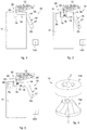
fig. 1 is a schematic representation of a device for grinding coffee beans according to embodiments described here; -
fig. 2 is a schematic representation of a device for grinding coffee beans according to other embodiments described here; -
fig. 3 is a schematic representation of a device for grinding coffee beans according to other embodiments described here; -
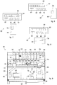
fig. 4 is a schematic representation of a part of a device for grinding coffee beans according to embodiments described here; -
fig. 5 is a section of a part of a device for grinding coffee beans according to embodiments described here; -
figs. 6, 7 and 8 are schematic representations of possible embodiments of a station for preparing coffee in which a device for grinding coffee beans according to other embodiments described here can be used; -
fig. 9 is a front view of part of a station for preparing coffee in which a device for grinding coffee beans according to other embodiments described here can be used. - To facilitate comprehension, the same reference numbers have been used, where possible, to identify identical common elements in the drawings. It is understood that elements and characteristics of one embodiment can conveniently be incorporated into other embodiments without further clarifications.
- We shall now refer in detail to the various embodiments of the present invention, of which one or more examples are shown in the attached drawings. Each example is supplied by way of illustration of the invention and shall not be understood as a limitation thereof. For example, the characteristics shown or described insomuch as they are part of one embodiment can be adopted on, or in association with, other embodiments to produce another embodiment. It is understood that the present invention shall include all such modifications and variants.
- Before describing these embodiments, we must also clarify that the present description is not limited in its application to details of the construction and disposition of the components as described in the following description using the attached drawings. The present description can provide other embodiments and can be obtained or executed in various other ways. We must also clarify that the phraseology and terminology used here is for the purposes of description only, and cannot be considered as limitative.
- The use of terms such as "including", "comprising", "having" and their variations is intended to include the elements listed after them and their equivalents, and also additional elements. Unless otherwise specified, terms such as "mounted", "connected", "supported" and "coupled" and their variations are used in the widest sense and include both direct and indirect assemblies, connections, supports and couplings. Furthermore, the terms "connected" and "coupled" cannot be limited to physical or mechanical connections or couplings.
- Embodiments described here concern a
device 10 and a method for grinding coffee beans. - We must point out here that grinding coffee beans as intended in the embodiments described here can be directed to produce a ground coffee powder usable for example for preparing espresso coffee. Espresso coffee is obtained by extracting rapidly, with hot water and/or steam at considerable pressure, substances contained in a compressed panel of ground coffee held on a filter. The extraction process can be influenced by various factors, including the grain size of the ground coffee, the specific surface of the granules and the compacting of the panel of ground coffee. Furthermore, in order to obtain a coffee with the desired and specific organoleptic properties of the mixture or type of coffee selected, different and variable profiles or trends of temperature and pressure can be applied, depending on the type of coffee selected.
- A
device 10 and a method for grinding coffee beans according to the present description can be used for example to grind coffee beans of different types, selected on each occasion according to a recipe or specific mixture and directed to the tastes and wishes of a final consumer. - For example, a
device 10 and a method for grinding coffee beans according to the present description can be used in association with an apparatus for the metered feed of coffee beans that allows to produce, with suitable repeatability and reliability, mixtures of coffee powder obtained by grinding selections of beans of different types of coffee, in particular according to personalized recipes or recipes that can be personalized by a user or specific operator. - One example of an apparatus for the metered feed of coffee beans usable in association with the present embodiments is described in the application for a patent of industrial invention in Italy n.
UD2015A000002 - Furthermore, a device and method according to the present description in association with an apparatus for the metered feed of coffee beans can be further associated with a selector device to produce personalized mixtures as described in the application for a patent of industrial invention in Italy n.
UD2014A000146 -
Fig. 1 is used to describe embodiments of adevice 10 for grindingcoffee beans 12. Thedevice 10 includes a grindingmember 14 configured to grindcoffee beans 12 and produce aground coffee powder 15, atransit chamber 16 configured to receive theground coffee powder 15 from the grindingmember 14, and adischarge member 18 configured to discharge theground coffee powder 15 arriving from thetransit chamber 16 toward the outside of thedevice 10. - According to the present description, the
device 10 also comprises at least one air-poweredpowder removal member 20 configured to generate a stream of air through the grindingmember 14, in order to removeground coffee powder 15 from the grindingmember 14 and from thetransit chamber 16. - According to some embodiments, a method is also provided for grinding
coffee beans 12 which comprises: - grinding
coffee beans 12 by means of a grindingmember 14 to produce aground coffee powder 15 that is made to transit through atransit chamber 16 and, by means of adischarge member 18 downstream of thetransit chamber 16, is then discharged toward a receiving container, such as a filter, a package or suchlike; - removing
ground coffee powder 15 from the grindingmember 14 and from thetransit chamber 16 by means of a stream of air generated by the air-poweredpowder removal member 20 through the grindingmember 14. - For example, as described in more detail hereafter, in possible implementations the stream of air generated through the grinding
member 14 to removeground coffee powder 15 from the grindingmember 14 and thetransit chamber 16 can develop along a path that passes through the grindingmember 14, thetransit chamber 16 and also thedischarge member 18, with reference for example to the embodiments described usingfigs. 1, 2 and5 and as indicated for example by the arrows infig. 2 . - In other possible implementations, the stream of air generated through the grinding
member 14 to removeground coffee powder 15 from the grindingmember 14 and thetransit chamber 16 can develop along a path that passes through thetransit chamber 16 and the grindingmember 14, with reference for example to the embodiments described usingfigs. 1, 3 and5 and as indicated for example by the arrows infig. 3 . - In possible implementations, the
device 10 can be provided with a grindingchamber 19 which houses the grindingmember 14. The grindingchamber 19 that houses the grindingmember 14 is in communication, downstream of the grindingmember 14, with thetransit chamber 16. The stream of air generated through the grindingmember 14 to removeground coffee powder 15 from the grindingmember 14 and thetransit chamber 16 therefore passes through the grindingchamber 19. - In possible implementations, the air-powered
powder removal member 20 can for example be disposed in an upper part of thedevice 10, in cooperation with the grindingmember 14. - In possible implementations, the
device 10 is provided with anentrance aperture 21 through which to feed the coffee beans, and anexit aperture 23 through which theground coffee powder 15 is discharged to the outside. Theentrance aperture 21 can be provided in an upper portion of thedevice 10. For example, the grindingchamber 19 can be provided with theentrance aperture 21. - In possible implementations, the air-powered
powder removal member 20 can be disposed near theentrance aperture 21, upstream of the grindingmember 14 and hence, generating a stream of air whose path passes through the grindingmember 14, can perform its removal action also on the grindingmember 14 itself, as well as on thetransit chamber 16. - The
entrance aperture 21 is associated with the grindingmember 14, while theexit aperture 23 is associated with thedischarge member 18. - Between the
entrance aperture 21 and theexit aperture 23, a working path therefore develops, working thecoffee beans 12 to groundcoffee powder 15. In particular, the working path affects the working steps from when thecoffee beans 12 are introduced into thedevice 10, in particular into the grindingchamber 19 where they are ground by the grindingmember 14, and then made to transit through thetransit chamber 16 and discharged by thedischarge member 18 toward the outside ascoffee powder 15. It is therefore possible to remove, by means of the air-poweredpowder removal member 20, the residual coffee powder from the working path, thanks to the stream of air generated through the grindingmember 14. Apowder expulsion channel 13 can be provided, which connects the grindingmember 14 to thetransit chamber 16 and which can therefore be part of the working path. The removal of the coffee powder by the air-poweredpowder removal member 20 can therefore take place in thepowder expulsion channel 13 as well. - In possible implementations, the
entrance aperture 21 is disposed in the upper part of thedevice 10, upstream of the grindingmember 14, and thetransit chamber 16 is disposed directly at exit from the grindingmember 14, for example adjacent at the side, that is, downstream of the latter with respect to the working path of the coffee, to receive theground coffee powder 15 from the grindingmember 14. Downstream of thetransit chamber 16, along the working path, thedischarge member 18 is provided. - In possible implementations, the grinding
member 14 can include two reciprocally mobile grinders, and can be configured to carry out the grinding by exploiting a relative rotation movement of the grinders of which it consists, as described in more detail hereafter. The rotation movement generates a centrifugal force acting on theground coffee powder 15, which directs it, for example essentially with a radial movement, toward thetransit chamber 16 and from here to thedischarge member 18. - In possible implementations, the
discharge member 18 can be a mechanical discharge member. For example, thedischarge member 18 can be a passive discharge member or an active discharge member, or a combination of the two. - For example, in some variants the
discharge member 18 can be the passive mechanical type and can exploit the force of gravity to make theground coffee powder 15 descend toward the outside of thedevice 10. In these variants, thedischarge member 18 for example can be a slide, a beak, a channel or inclined plane, which receives theground coffee powder 15 thrust by the centrifugal force of the grindingmember 14 and sends it toward the outside of thedevice 10. - In other variants, the
discharge member 18 can be the active mechanical type, for example it can be a mobile member that thrusts or draws theground coffee powder 15 from thetransit chamber 16 toward the outside. In these variants, thedischarge member 18 can be for example a sideboard, a spatula, a blade, a bar or suchlike. - According to some embodiments described here, the air-powered
powder removal member 20 can be used for example after a large part or most of theground coffee powder 15 has already been discharged by thedischarge member 18, for example due to gravity and exploiting the centrifugal force imparted by the grindingmember 14. This is to remove possible residualground coffee powder 15 that can still be present in thetransit chamber 16 and possibly in thedischarge member 18 and that has not been carefully discharged, for example because it has remained adhering to the surfaces. This removal action allows to eliminate from thetransit chamber 16 and possibly from thedischarge member 18 essentially all theground coffee powder 15 produced in one grinding operation, so that, after a new grinding operation, thetransit chamber 16 will contain only the newground coffee powder 15. This solution allows to prevent cross contamination of the various mixtures ofground coffee powder 15 that are prepared in succession, guaranteeing that every individual mixture of coffee powder is characterized by its own organoleptic properties and not influenced by the organoleptic properties of other different mixtures prepared before it. Therefore, there is no carry-over of different mixtures of coffee powder prepared in series. In this way, each mixture of coffee powder preserves its own unique characteristics defined during a careful selection of types and doses of quantities of coffee beans. - For example, after it has been discharged from the
transit chamber 16, theground coffee powder 15 prepared according to the present description can be received outside thedevice 10 in a filter associated with a filter-carrier, subsequently compressed in a press, obtaining a compact panel of ground coffee which is then subjected to extraction to prepare the espresso coffee drink. Each portion ofground coffee powder 15 prepared according to the present description is therefore received in the filter, pressed and subjected to extraction, allowing to prepare an espresso coffee drink that corresponds to the recipe initially selected by the user or operator, without contamination with other mixtures. - In any case, in other example applications, after it has been discharged and removed from the
transit chamber 16, there is nothing to prevent theground coffee powder 15 prepared according to the present description from being received and collected in a package or container, which is then closed or sealed to be used at a later time. - In possible implementations, the
device 10 can include a single air-poweredpowder removal member 20, but variant embodiments are possible which include several air-poweredpowder removal members 20, for example two, three or more than three. If there is a plurality of air-poweredpowder removal members 20, they can be positioned with a geometry correlated to the removal effect of theground coffee powder 15 that is to be obtained, or alternatively, or in combination, they can be configured to generate air-powered removal phenomena characterized by different fluidic parameters, such as pressure or depression of the stream of air, speed of the stream of air, duration, type of stream (continuous or pulsed), sequence of the intervention. - According to possible embodiments described using
fig. 2 , the air-poweredpowder removal member 20 can include a compressedair pneumatic member 22, in particular a compressed air blowing member, such as for example provided with a nozzle, pipette or similar delivery element, connected to a compressed air source. For example, according to other possible embodiments described usingfig. 2 , thedevice 10 can include apressurized container 28 containing compressed air that functions as a source of compressed air and that can be rechargeable or replaceable. In other variants, thedevice 10 can be connected to a pneumatic line supplying compressed air. - For example, the
pneumatic member 22 can be disposed so as to generate the stream of air that passes through the grindingmember 14 and hits the inside of thetransit chamber 16 with a stream of compressed air which is able to remove the residualground coffee powder 15 present, and directs it toward thedischarge member 18, from which it is transferred toward the outside of thedevice 10, where for example it is received by the filter as described above, or introduced into a package or container for subsequent use. In possible implementations, thepneumatic member 22 can be configured to supply a continuous stream of compressed air, or a pulsed stream of compressed air, or a combination of the two. For example, a continuous stream of compressed air can have a duration comprised between 2 and 15 seconds, in particular between 4 and 12 seconds, more particularly between 6 and 10 seconds, or combinations of such intervals. - According to other possible embodiments described using
fig. 3 , the air-poweredpowder removal member 20 can include anair suction member 24, that is, a member that generates a depression that sucks up the air and hence the possible residualground coffee powder 15. The embodiments where the air-poweredpowder removal member 20 includes anair suction member 24 can be alternative to the embodiments where the air-poweredpowder removal member 20 includes apneumatic member 22. - The
air suction member 24 can be connected to asuction source 29, which generates a depression or vacuum condition. In this way, theair suction member 24 can generate a stream of aspirated air inside thetransit chamber 16, sucking up and removing the residualground coffee powder 15 present therein and possibly present in thedischarge member 18, and can generate the stream of air that passes through the grindingmember 14. - In possible implementations, the
ground coffee powder 15 sucked up can be directly recovered and sent to thedischarge member 18. - In other possible implementations, according to other possible embodiments described using
fig. 3 , thedevice 10 can include a residual powder accumulation tank 30. In this way, theground coffee powder 15 sucked in by theair suction member 24 can be received in the residual powder accumulation tank 30, which can be emptied as required. The residual powder accumulation tank 30 can be disposed between theair suction member 24 and thesuction source 29. It can be provided that theground coffee powder 15 sucked into the residual powder accumulation tank 30 is disposable, and therefore eliminated. Alternatively, it can be provided that theground coffee powder 15 that is sucked into the residual powder accumulation tank 30 is recovered and sent to thedischarge member 18, advantageously with every grinding of a specific dose, so as to prevent cross contamination and carry-over in the residual powder accumulation tank 30. - In possible embodiments, combinable with all the embodiments described here, the
device 10 can comprise or be associated with a system controller orcontrol board 100. - In particular, the
system controller 100 can be configured to manage, command and control the functioning of thedevice 10 and the execution for example of the necessary cleaning cycles of the ground coffee powder, as described above, and also the execution of grinding cycles and the adjustment of the degree of grinding, as explained in more detail hereafter. - In particular, in possible example implementations, the
system controller 100 can be configured to communicate with the outside, for example by association or integration with a suitable communication module, chosen according to the communication type and protocol used. For example, communication may be obtained by a cabled data connection, for example an Ethernet connection, for example LAN (Local Area Network), or a serial connection, such as RS232, or a USB connection or other. Otherwise, the communication can be obtained by a wireless data connection, for example radio, Wi-Fi protocol, or Bluetooth ®, ZigBee, NFC (Near Field Communication), or infrared (Infrared Data Association, IrDA). - In some embodiments, the
system controller 100 can include a microcontroller, or a microchip, or a central processing unit or CPU, associated with an electronic memory, possibly an electronic database and auxiliary circuits (or I/O). - For example, the CPU can be any form of computer processor used in the IT field for controlling apparatuses and devices in the field in question. The memory can be connected to the CPU and can be one of those commercially available, such as a random access memory (RAM), a read-only memory (ROM), floppy disk, hard disk, mass memory or any other form of digital archive, local or remote. The software instructions and data can be for example encoded and memorized in the memory to command the CPU. The auxiliary circuits can also be connected to the CPU to assist the processor in a conventional manner. The auxiliary circuits can include for example at least one of: cache circuits, feed circuits, clock circuits, input/output circuits, subsystems and suchlike. A program (or computer instructions) can determine which tasks can be done in accordance with the method according to the present description.
- In possible embodiments described using
fig. 4 and combinable with all the embodiments described here, the grindingmember 14 can include a pair ofgrinders grinders grinders - Moreover, the
grinders grinder 14a or rotor can be provided that is mobile during grinding, and one fixedgrinder 14b or stator that is stationary during grinding. The terms "mobile/rotor" and "fixed/stator" refer to the respective condition of thegrinders - The reciprocal movement of the
grinders actuation element 31. - According to some embodiments, the
actuation element 31 can be commanded and controlled by saidsystem controller 100. - Usually, an
actuation element 31 as used in association with embodiments described here can be an actuator with an intrinsically rotary movement or be configured to convert a linear movement into a circular movement. The conversion can be commonly done by means of types of mechanism selected from a group consisting of: screw actuators, such as a jack screw, ball screw actuators and roll screw actuators, or wheel and axle, for example drum, gears, pulley or shaft actuators, such as a lifting cable, a winch, a rack and a pinion group, a chain transmission, a belt transmission, actuators with a rigid chain and a rigid belt. According to some embodiments, theactuation element 31 can include adrive member 32, provided with adrive shaft 34 and configured to determine the desired reciprocal movement of thegrinders drive member 32 is made to function by a source of energy, for example electric current, a hydraulic pressure fluid or a pneumatic pressure. Thedrive shaft 34 can be coupled with arespective bearing 34a. Abase body 45 can be provided, which supports theactuation element 31, in particular thedrive member 32. Adrive member 32 as used in association with the embodiments described here can be a drive member chosen from a group comprising: an electric motor, a step electric motor, open squirrel cage or open coil electric motor, closed squirrel cage or closed coil electric motor, a magnetic motor, a linear axle with a motor, a linear motor, such as a mechanical linear motor, a piezoelectric linear motor, an electromagnetic linear motor, an electromechanical motor, an electromagnet, a gear motor, in particular a direct current gear motor. - In some embodiments, the
grinders fig. 5 for example). In particular, thegrinder 14a can be made to rotate around the central axis Z while the fixedgrinder 14b remains stationary. To this purpose, thegrinder 14a can be connected to thedrive shaft 34, driven by the drive member 32 (seefig. 5 for example). - In possible implementations, the
grinders grinders grinders - In implementations where the
grinders grinder 14a is internal, that is, it is disposed inside thegrinder 14b, which therefore completely surrounds it on the outside. - The grinding operation actuated by the grinding
member 14 can typically be influenced by different constructional and operating parameters. The constructional parameters are generally fixed and decided by the manufacturer of the grinders, such as geometry of the body and the grinding teeth, friction and surface hardness of the grinders, connected to the materials and workings used. The operating parameters can be variable, depending on the ingredients used, the atmospheric conditions and the desired result in the cup, such as for example the distance between thegrinders grinders - In possible embodiments, the relative distance between the
grinders ground coffee powder 15. Advantageously, the range of size in the adjustment of the distance is in micrometers. The distance can be adjusted manually, or automatically or semiautomatically. Consequently, thegrinders - For example, to adjust the distance,
grinder 14a can be made to move axially away from/toward thegrinder 14b. The possibility thatgrinder 14b is mobile with respect togrinder 14a for the purpose of adjusting the reciprocal distance must not be understood here as in contrast with the fact thatgrinder 14b remains stationary andgrinder 14a is made to move during the grinding operation. Furthermore, the operation to adjust the distance between thegrinders - In particular, the adjustment can be made by making
grinder 14b rotate around the central axis Z, whilegrinder 14a is kept stationary. - In possible implementations, with every complete turn,
grinder 14b descends by a determinate descent length and therefore is distanced fromgrinder 14a by a length correlated to the trigonometric function of the sine of the angle of inclination and the descent length. With every degree of rotation,grinder 14b moves nearer/away, depending on the direction of rotation, to/fromgrinder 14a by a distance in the order of some micrometers, in particular between 0.5 micron and 2 micron, more particularly between 0.75 micron and 1.5 micron, for example 1 micron. It is possible to control the movement ofgrinder grinder 14a andgrinder 14b can be disposed at a variable distance from each other to selectively define a grinding space or gap correlated to a desired grain size of theground coffee powder 15 to be obtained. -
Fig. 5 is used to describe embodiments, combinable with all the embodiments described here, in which anautomatic adjustment unit 35 is provided, configured to adjust the reciprocal distance between thegrinders fig. 5 can be combined both with the embodiments described in general usingfig. 1 , and also with the specific embodiments described usingfig. 2 , that is, in the case of the stream of compressed air, and also with the specific embodiments described usingfig. 3 , that is, in the case of a stream of sucked in air. - In some embodiments, the
automatic adjustment unit 35 can be commanded and controlled by, or by means of, thesystem controller 100. In other embodiments, theautomatic adjustment unit 35 can be commanded and controlled directly from outside, and not by or by means of thesystem controller 100. - In some embodiments, the
automatic adjustment unit 35 can be associated with the grindingchamber 19. - In some embodiments, combinable with all the embodiments described here, the
automatic adjustment unit 35 can include anadjustment body 36, associated for example connected to thegrinder 14b. - The
adjustment body 36 is configured mobile, so as to allow to positiongrinder 14b with respect togrinder 14a for the purposes of the adjustment. Theadjustment body 36 can be hollow, defining saidentrance aperture 21. The air-poweredpowder removal member 20 can be completely or partly inserted into theadjustment body 36 and perform its removal function on the grindingmember 14 and what is downstream of the latter, that is, possibly, thepowder expulsion channel 13, thetransit chamber 16, and possibly thedischarge member 18. Theadjustment body 36 can have a tubular shape, like a sleeve, a cup, a cylinder or suchlike. - In some embodiments, combinable with all the embodiments described here, the
adjustment body 36 is axially associated along the central axis Z with asupport body 38 by means of a threadedcoupling 40. The threadedcoupling 40 is defined by a threaded external surface of theadjustment body 36 and a mating threaded internal surface of the support body 38 (threaded system screw/lead screw). For example, thesupport body 38 can internally delimit the grindingchamber 19. - For example, the
adjustment body 36 can be inserted, in particular, inside thesupport body 38, more particularly theadjustment body 36 can be inserted into the grindingchamber 19. Since it can be screwed to thesupport body 38, theadjustment body 36 is mobile with respect to thesupport body 38, in rotation around the central axis Z and axially along the same axis Z. Furthermore, theadjustment body 36 is solidly connected togrinder 14b, for example by one or more screws 37. In this way, theadjustment body 36 drawsgrinder 14b in movement with it, causing it to advance/retreat along the central axis Z. Thanks to the threadedcoupling 40, by rotating theadjustment body 36 an axial displacement is also determined, advancing or retreating depending on the direction of rotation, of theadjustment body 36 and hence ofgrinder 14b. This displacement along the central axis Z therefore allows to modify the amplitude of the gap between thegrinders - In some embodiments, combinable with all the embodiments described here, the
automatic adjustment unit 35 can also include anactuation element 48, configured to supply movement for the reciprocal positioning of thegrinders automatic adjustment unit 35 can also include asystem 41 to transmit motion from theactuation element 48 to theadjustment body 36, so as to transmit the necessary movement to drive theadjustment body 36 and selectively define the reciprocal position of thegrinders - In possible example implementations, the
motion transmission system 41 can include adrive transmission part 46, associated, for example connected, with theactuation element 48, and a driventransmission part 42 associated, for example connected, with theadjustment body 36. Furthermore, amotion transmission member 44 can be provided, associated, for example connected, with thedrive transmission part 46 and the driventransmission part 42. - In possible example implementations, the
motion transmission system 41 can be the type with belt and pulley, chain, chain and gears, gears, worm screw and pinion, epicycloid members or other motion transmission systems. - For example, the
motion transmission member 44 can be chosen from either a belt, a flat belt, a trapezoid belt, a toothed belt, a rigid belt, a chain, a toothed chain, a chain with gears, a rigid chain, a series of gears, a rack or suchlike, or combination thereof. - For example, the
drive transmission part 46 and the driventransmission part 42 can be chosen, in coordination and homogeneously with respect to each other, from pulleys, toothed wheels, gear wheels, gears, worm screws, pinion or suchlike, or a combination thereof. The choice of thedrive transmission part 46 and the driventransmission part 42 is made in coordination with the type ofmotion transmission member 44 used. - In some embodiments, the
actuation element 48 is configured to actuate the rotation movement of thedrive transmission part 46. Advantageously, theactuation element 48 can be configured to supply a rotation motion both clockwise and anti/clockwise, according to needs. The motion of thedrive transmission part 46 is transmitted, by means of themotion transmission member 44, to the driventransmission part 42 which therefore makes theadjustment body 36 rotate, in one direction of rotation or the other, thus allowing, as described above, to adjust the distance between thegrinders actuation element 48 can include adrive member 47, also called positioning drive member because it is involved in the movement to adjust the reciprocal positioning of thegrinders drive shaft 49. With regard to the possible implementations ofactuation element 48 and drivemember 47 usable in combination with the embodiments described here, the description regarding theactuation element 31 and thedrive member 32 can apply. - Advantageously, the
automatic adjustment unit 35 is configured so that, with every degree of rotation of the driventransmission part 42, and hence theadjustment body 36, there is a corresponding micrometric movement of adjustment, in particular between 0.5 micron and 2 micron, more particularly between 0.75 micron and 1.5 micron, for example about 1 micron, ofgrinder 14b with respect togrinder 14a. Advantageously, an angular position transducer orencoder 43 can be provided, associated with thedrive member 47, in particular with therespective drive shaft 49, by means of which to precisely command and control the angular rotation supplied by thedrive member 47 to thedrive transmission part 46 and hence to reliably and precisely control the adjustment of the grain size. In particular, thanks to the angular position transducer orencoder 43, it is possible to precisely control the degrees of rotation ofgrinder 14b and hence its movement away from/toward thegrinder 14a as described above. - In possible embodiments, the
automatic adjustment unit 35 can be configured to move thegrinders grinders - In said zero position, therefore, the
grinders grinders - This solution allows to deal with possible shifts in the reciprocal position of the
grinders grinders grinders opening grinder 14a with respect togrinder 14b, the adjustment can be carried out each time with respect to the same zero position, and therefore with an increased precision of said adjustment. - In advantageous embodiments, the
automatic adjustment unit 35 can be commanded and controlled remotely, for example by thesystem controller 100 or from the outside, for the purposes of the various adjustment operations described here. To this purpose, theautomatic adjustment unit 35 can be associated with a communication module. The communication module can be for example the same as, or be configured like, the communication module associated with thesystem controller 100. - For example, the
automatic adjustment unit 35 can be commanded remotely, directly or by thesystem controller 100, a mobile communication device, such as for example a smartphone, a palmtop, a tablet, a portable computer, a fixed computer or other, advantageously by a software application associated with the mobile communication device, for example executed thereon or executed remotely. - In embodiments described using
fig. 5 , combinable with all the embodiments described here, arotary element 39 can be provided, associated with the grindingmember 14, able to facilitate the expulsion of theground coffee powder 15 toward thetransit chamber 16. In implementations described here, therotary element 39 can be connected togrinder 14a and can rotate solidly therewith during grinding. Therotary element 39 can be disposed undergrinder 14a andgrinder 14b can be disposed at a distance from therotary element 39 such as to define thepowder expulsion channel 13. For example, therotary element 39 can be a plate or disc, possible shaped. - In possible embodiments, combinable with all the embodiments described here, the
device 10 can include anexternal body 11, or chassis or base or support frame, which encloses the internal components, in particular the grindingmember 14, thetransit chamber 16 and the necessary components and actuation, feed and control members. - Furthermore, in possible implementations, the
device 10 can include afeed member 26 configured to receive the coffee beans and to feed them to the grindingmember 14. Thefeed member 26 can be for example a loading hopper, a slide, a shaped collector, a funnel or other equivalent member. - In possible embodiments, combinable with all the embodiments described here, the
device 10 can include adelivery mouth 27, which is disposed on theexternal body 11 of thedevice 10 and is in communication with thedischarge member 18 from which it receives theground coffee powder 15 to direct it, for example, to a filter, or to a package or container. - In possible embodiments, combinable with all the embodiments described here, the
device 10 can include anupper covering element 50, provided to cover and protect theentrance aperture 21 for thecoffee beans 12 to the grindingmember 14. The coveringelement 50 can be provided with anaperture 50a through which thefeed member 26 is inserted, to pour thecoffee beans 12 toward the grindingmember 14. The coveringelement 50 can be provided with one ormore apertures 50b for the passage of themotion transmission member 44. One example of anupper covering element 50 can be a plate, a panel, a cap or suchlike. -
Figs. 6, 7 and 8 are used to describe embodiments, combinable with all the embodiments described here, of astation 80 for preparing coffee, which includes anapparatus 68 to feed metered quantities of coffee beans to supply a mixture ofcoffee beans 12 with a desired composition, adevice 10 according to the present description, and acoffee machine 78, able to produce the coffee drink, in particular espresso coffee, from the mixture of coffee powder obtained by grindingcoffee beans 12. - In possible implementations, the
station 80 for preparing coffee includes asection 82 to prepare the coffee powder mixture, which includes thedevice 10 and theapparatus 68 to feed metered quantities of coffee beans, and asection 84 to prepare the coffee drink which includes thecoffee machine 78.Figs. 6, 7 and 8 are used to describe various possible layouts of thestation 80 for preparing coffee with a different reciprocal disposition of thesection 82 to prepare the coffee powder mixture and thesection 84 to prepare the coffee drink. According to some embodiments, described usingfigs. 6 and 7 , thesection 82 to prepare the coffee powder mixture can be disposed transverse, for example orthogonal, to thesection 84 to prepare the coffee drink. The disposition of thesection 82 to prepare the coffee powder mixture can be at the side of thesection 84 to prepare the coffee drink (seefig. 6 ) or in an intermediate position (seefig. 7 ). - According to other embodiments, described using
fig. 9 , thesection 82 to prepare the coffee powder mixture can be disposed parallel, for example substantially in front in an opposite position, to thesection 84 to prepare the coffee drink. -
Fig. 9 is used for describing embodiments of asection 82 to prepare the coffee powder mixture which includes anapparatus 68 to feed metered quantities of coffee beans which provides a multiplicity or array ofmetering units 51 configured to measure out thecoffee beans 12 in individual doses, and an incremental weighingunit 53 configured to weigh a quantity of coffee beans metered by themetering unit 51. - Each
metering unit 51 can include afeed device 52 configured to feed the coffee beans in loose form. For example, eachmetering unit 51 can be associated with different types of coffee so that each feeds individual doses of coffee beans of different variety and type, so as to generate all in all a mixture ofcoffee beans 12 which will have the desired composition, that is, desired and specific quantities of coffee beans of different types, which can be chosen by the consumer or user according to his/her own personal taste. - Furthermore, the incremental weighing
unit 53 can include acontainer 58 to receive the coffee beans transferred by eachmetering unit 51, and a sensor unit configured to detect the weight force acting on thecontainer 58 defined on each occasion by the coffee beans which are successively introduced therein, so that, at the end of the various metering operations, there is a quantity of mixture ofcoffee beans 12 present in thecontainer 58 that is the desired quantity and final composition, which will then be ground by thedevice 10. - The
section 82 to prepare the coffee powder mixture includes aframe 86 which supports theapparatus 68 to feed metered quantities of coffee beans and possibly also thedevice 10. A plurality oftransfer members 96 are provided, each coupled with arespective feed device 52 of arespective metering unit 51, which function as a system to feed the coffee beans. Amovement device 74 is also provided, configured to move acontainer 58 associated with a sensor unit with respect to thefeed devices 52. - In possible implementations, the
device 10 according to the present description is put into cooperation with the array ofmetering units 51, and can receive the mixture of coffee beans ready from thecontainer 58. To this purpose, an upendingmember 75 is provided on themovement device 74, and is configured to act on thecontainer 58 when the latter is aligned with thedevice 10, in particular when for example it is associated with thefeed member 26. Theframe 86 comprises asupport plane 88 which supports thedevice 10. A pressing device or tamper 90 can also be provided, to tamp the coffee powder, which can be disposed on thesupport plane 88, for example next to thedevice 10. Avacuum packaging device 92 can also be provided, to vacuum pack in a suitable package, container, bag or sachet the metered coffee beans or the coffee powder produced by thedevice 10, if they are not used immediately but supplied for subsequent use. Thevacuum packaging device 92 can also be disposed on thesupport plane 88, for example next to thepressing device 90. A user/operator interface 62 can also be provided, for example a touchscreen, also on thesupport plane 88. Furthermore, if the weighed mixture of coffee beans is not introduced into thedevice 10 and ground, but supplied such as it is, then adischarge system 94 can be provided, which can receive the coffee beans from thecontainer 58 and, for example, transfer them or pour them into a suitable package which then, for example, can be vacuum packed. - It is clear that modifications and/or additions of parts may be made to the
device 10 and method for grinding coffee beans as described heretofore, without departing from the field and scope of the present invention. - For example, in possible embodiments, combinable with all the embodiments described here, a system of packings can be provided, at least in correspondence with the
bearing 34a of thedrive shaft 34 associated with thedrive member 32 described for example usingfig. 5 , to seal the upper grindingchamber 19 from the lower part of thedevice 10, that is, the lower chamber where thedrive member 32 is housed, preventing the entrance and deposit of the ground coffee powder. - This solution can be advantageous to insulate the
drive member 32 below, so as to prevent leakage of powders and the consequent risk of explosions which could be caused by the presence or accidental entrance, in the lower chamber where thedrive member 32 is housed, of fine powder of ground coffee and sparks or potential explosions of other type. - To this purpose, moreover, it can be advantageous to use an
electric drive member 32 of the closed squirrel cage type, to protect thedrive member 32 and prevent the fine powder of ground coffee from entering into and depositing inside thedrive member 32 itself. - It is also clear that, although the present invention has been described with reference to some specific examples, a person of skill in the art shall certainly be able to achieve many other equivalent forms of device and method for grinding coffee beans, having the characteristics as set forth in the claims and hence all coming within the field of protection defined thereby.
- Although the above refers to embodiments of the invention, other embodiments can be provided without departing from the main field of protection, which is defined by the following claims.
- In the following claims, the sole purpose of the references in brackets is to facilitate reading: they must not be considered as restrictive factors with regard to the field of protection claimed in the specific claims.
Claims (22)
- Device for grinding coffee beans (12), characterized in that said device comprises:- a grinding member (14) configured to grind coffee beans (12) and produce a ground coffee powder (15), said grinding member (14) comprising two reciprocally mobile grinders;- a grinding chamber (19) housing said grinding member (14);- a transit chamber (16) configured to receive the ground coffee powder (15);- a discharge member (18) configured to discharge the ground coffee powder (15) arriving from the transit chamber (16) toward the outside of said device;- at least one air-powered powder removal member (20) configured to generate a stream of air through said grinding member (14), in order to remove ground coffee powder (15) from the grinding member (14) and from the transit chamber (16);
said grinding chamber (19) being in communication, downstream of the grinding member (14), with the transit chamber (16), said stream of air generated through the grinding member (14) and the respective two reciprocally mobile grinders, to remove ground coffee powder (15) from the grinding member (14) and the transit chamber (16) passing through the grinding chamber (19); wherein said device is provided with an entrance aperture (21) through which to feed the coffee beans and an exit aperture (23) through which the ground coffee powder (15) is discharged to the outside, wherein the entrance aperture (21) is associated with the air-powered powder removal member (20) and with the grinding member (14), and the exit aperture (23) is associated with the discharge member (18). - Device as in claim 1, wherein a working path develops between the entrance aperture (21) and the exit aperture (23), working coffee beans (12) to ground coffee powder (15).
- Device as in claim 2, wherein the entrance aperture (21) is disposed in an upper part of the device, upstream of the grinding member (14) and the air-powered powder removal member (20) is disposed in correspondence to said entrance aperture (21) and the transit chamber (16) is disposed directly downstream of the grinding member (14) with respect to the working path of the coffee, to receive the ground coffee powder (15) from the grinding member (14), and the discharge member (18) is provided downstream of the transit chamber (16), along the working path of the coffee.
- Device as in any claim from 1 to 3, wherein said device comprises a single air-powered powder removal member (20).
- Device as in any claim from 1 to 3, wherein said device comprises several air-powered powder removal members (20).
- Device as in any claim from 1 to 5, wherein said air-powered powder removal member (20) comprises a pneumatic member (22) with compressed air, in particular a member for blowing in compressed air.
- Device as in any claim from 1 to 5, wherein said air-powered powder removal member (20) comprises an air suction member (24).
- Device as in any claim from 1 to 7, wherein said grinding member (14) comprises a pair of grinders (14a, 14b) coaxial with respect to a common central axis (Z).
- Device as in claim 8, wherein said device comprises an automatic adjustment unit (35) configured to adjust a reciprocal distance between the grinders (14a, 14b) and which comprises an adjustment body (36) connected to grinder (14b) and mobile, so as to allow the positioning of grinder (14b) with respect to grinder (14a) for the adjustment, the adjustment body (36) being associated axially along the central axis (Z) to a support body (38) by means of a threaded coupling (40).
- Device as in claim 9, wherein said automatic adjustment unit (35) comprises a drive transmission part (46), associated with an actuation element (48), a driven transmission part (42) associated with the adjustment body (36), a motion transmission member (44) associated with the driven transmission part (42) and the drive transmission part (46).
- Device as in claim 10, wherein a micrometric adjustment movement of grinder (14b) with respect to grinder (14a) corresponds to every degree of rotation of the driven transmission part (42).
- Station for preparing coffee, characterized in that said station comprises an apparatus (68) to feed metered quantities of coffee beans to supply a mixture of coffee beans (12) with a desired composition, a device (10) to grind coffee beans (12) according to any claim from 1 to 11, and a coffee machine (78), able to produce the coffee drink from the mixture of coffee powder obtained.
- Station as in claim 12, wherein said apparatus (68) to feed metered quantities of coffee beans comprises:- an array of metering units (51) each configured to measure out the coffee beans (12) in individual doses and provided with a feed device (52) configured to feed coffee beans in loose form;- an incremental weighing unit (53) configured to weigh a quantity of coffee beans metered by the metering unit (51), and provided with a container (58) to receive the coffee beans transferred from each metering unit (51), and with a sensor unit configured to detect the weight force acting on the container (58).
- Station as in claim 12 or 13, wherein said station comprises a section (82) to prepare the coffee powder mixture, which comprises said device (10) for grinding coffee beans (12) and said apparatus (68) to feed metered quantities of coffee beans, and a section (84) to prepare the coffee drink which comprises the coffee machine (78).
- Station as in claim 14, wherein said section (82) to prepare the coffee powder mixture comprises a frame (86) that supports the apparatus (68) to feed metered quantities of coffee beans.
- Station as in claim 14 or 15, wherein said section (82) to prepare the coffee powder mixture comprises:- a plurality of transfer members (96), each coupled to a respective feed device (52) of a respective metering unit (51), to transfer the coffee beans (12);- a movement device (74) configured to move, with respect to the feed devices (52), a container (58) to receive the coffee beans and associated with a sensor unit configured to detect the weight force acting on the container (58).
- Station as in claim 14, 15, or 16, wherein the movement device (74) comprises an upending member (75) to upend the container (58), wherein said device (10) is located in cooperation with the array of metering units (51), receiving the coffee beans from the container (58) upended by the upending member (75).
- Station as in any claim from 14 to 17, wherein said section (82) to prepare the coffee powder mixture also comprises a pressing device (90) to press the coffee powder.
- Method for grinding coffee beans (12), characterized in that said method comprises:- grinding coffee beans (12) by means of a grinding member (14) comprising two reciprocally mobile grinders, said grinding member (14) being comprised in a device provided with an entrance aperture (21) through which to feed the coffee beans and an exit aperture (23) through which the ground coffee powder (15) is discharged to the outside, and in communication, downstream of the grinding member (14), with a transit chamber (16), to produce a ground coffee powder (15) that is made to transit through the transit chamber (16) and, by means of a discharge member (18), is then discharged toward a receiving container, wherein the entrance aperture (21) is associated with the grinding member (14), and the exit aperture (23) is associated with the discharge member (18);- removing ground coffee powder (15) from the grinding member (14) and from the transit chamber (16) by means of a stream of air generated through said grinding member (14) by at least one air-powered powder removal member (20) associated with said entrance aperture (21), upstream of said grinding member (14);
wherein said stream of air generated by said at least one air-powered powder removal member (20) through the grinding member (14) and the respective two reciprocally mobile grinders, to remove ground coffee powder (15) from the grinding member (14) and the transit chamber (16), passes through said grinding chamber (19). - Method as in claim 19, wherein the stream of air is obtained by blowing in compressed air.
- Method as in claim 19, wherein the stream of air is obtained by means of air suction.
- Method for preparing coffee, characterized in that said method comprises:- feeding metered quantities of coffee beans (12) to supply a mixture of coffee beans (12) with a desired composition;- grinding the coffee beans (12) into the desired composition in accordance with a method as in any claim from 19 to 21;- producing the coffee drink from a mixture of ground coffee powder (15) obtained from grinding.
Applications Claiming Priority (2)
| Application Number | Priority Date | Filing Date | Title |
|---|---|---|---|
| ITUD2015A000048A ITUD20150048A1 (en) | 2015-04-14 | 2015-04-14 | DEVICE AND METHOD FOR GRINDING COFFEE BEANS |
| PCT/EP2016/058232 WO2016166216A1 (en) | 2015-04-14 | 2016-04-14 | Device and method for grinding coffee beans |
Publications (2)
| Publication Number | Publication Date |
|---|---|
| EP3282906A1 EP3282906A1 (en) | 2018-02-21 |
| EP3282906B1 true EP3282906B1 (en) | 2020-11-04 |
Family
ID=53267512
Family Applications (1)
| Application Number | Title | Priority Date | Filing Date |
|---|---|---|---|
| EP16718630.3A Active EP3282906B1 (en) | 2015-04-14 | 2016-04-14 | Device and method for grinding coffee beans |
Country Status (4)
| Country | Link |
|---|---|
| US (1) | US10729284B2 (en) |
| EP (1) | EP3282906B1 (en) |
| IT (1) | ITUD20150048A1 (en) |
| WO (1) | WO2016166216A1 (en) |
Families Citing this family (25)
| Publication number | Priority date | Publication date | Assignee | Title |
|---|---|---|---|---|
| IT201700038863A1 (en) * | 2017-04-07 | 2018-10-07 | Mazzer Luigi Spa | COFFEE GRINDER WITH COFFEE DUST PROTECTION |
| AU2018270221B2 (en) | 2017-05-16 | 2022-03-03 | Nicholson Design Consultants Limited | Bean grinding apparatus |
| WO2019076872A1 (en) * | 2017-10-18 | 2019-04-25 | Conti Valerio - S.R.L. | Coffee grinder with ejection device |
| IT201700118492A1 (en) * | 2017-10-19 | 2019-04-19 | Mazzer Luigi Spa | COFFEE GRINDER WITH REPOSITIONABLE SYSTEM FOR INDICATION OF THE POSITION OF THE MEANS OF ADJUSTMENT OF THE DISTANCE BETWEEN THE MILLS |
| IT201800006831A1 (en) * | 2018-06-29 | 2019-12-29 | Device for conveying at least one powdered ingredient, preferably coffee powder. | |
| IT201900001629A1 (en) * | 2019-02-05 | 2020-08-05 | La Marzocco Srl | Coffee grinder machine configured to provide different particle size profiles and relative method |
| CN110141114A (en) * | 2019-04-26 | 2019-08-20 | 上海炫未智能科技有限公司 | A device for automatically extracting tea and its implementation method |
| EP3982745A4 (en) * | 2019-06-13 | 2023-12-13 | Ricconics LLC | Coffee system and method |
| IT201900014904A1 (en) * | 2019-08-21 | 2021-02-21 | Drm S R L | Anticlumping ground coffee |
| EP3804586B1 (en) * | 2019-10-10 | 2022-01-26 | Hemro International AG | Coffee mill |
| CH716693A2 (en) * | 2019-10-14 | 2021-04-15 | Steiner Ag Weggis | Method for producing coffee and a device for carrying out the method. |
| IT201900018827A1 (en) * | 2019-10-15 | 2021-04-15 | Drm S R L | Device and method for cleaning grinders |
| IT201900024274A1 (en) * | 2019-12-17 | 2021-06-17 | Girardi S R L | PROCEDURE AND GRINDING SYSTEM |
| DE102020109528A1 (en) * | 2020-04-06 | 2021-10-07 | Melitta Professional Coffee Solutions GmbH & Co. KG | Method for adjusting the degree of grind of a grinder, and the degree of adjustment of a grinder |
| DE102020109527A1 (en) * | 2020-04-06 | 2021-10-07 | Melitta Professional Coffee Solutions GmbH & Co. KG | Grind adjustment arrangement with a coffee machine, coffee machine of such an arrangement, and method for adjusting the grinding degree |
| CN113768379B (en) * | 2021-10-28 | 2025-10-28 | 中山市峻国电器有限公司 | A coffee bean grinder capable of achieving coarse and fine separation |
| US12622542B2 (en) | 2022-03-14 | 2026-05-12 | TBDx Inc. | Automatically adjustable coffee grinder for a coffee brewing system |
| IT202300002028A1 (en) | 2023-02-07 | 2024-08-07 | Illycaffe Spa | METHOD AND APPARATUS FOR CALIBRATING A COFFEE GRINDER |
| CN116019371B (en) * | 2023-02-17 | 2025-05-30 | 玛西(北京)国际品牌管理有限公司 | Bean grinding method and device, electronic equipment and storage medium |
| TWI909252B (en) * | 2023-11-19 | 2025-12-21 | 南開科技大學 | An intelligent coffee bean blending system |
| US12369744B1 (en) | 2024-01-18 | 2025-07-29 | Sharkninja Operating Llc | Preparation of beverage machines for cold beverage brewing |
| WO2025155321A1 (en) | 2024-01-18 | 2025-07-24 | Sharkninja Operating Llc | Suggesting coffee bean grind size for beverage machines |
| WO2025155323A1 (en) | 2024-01-18 | 2025-07-24 | Sharkninja Operating Llc | Preventing coffee bean grinder jamming |
| WO2025153293A1 (en) * | 2024-01-19 | 2025-07-24 | De' Longhi Appliances S.R.L. | Grinder for grinding loose material including vegetable seeds or fruits |
| CN117958605A (en) * | 2024-02-28 | 2024-05-03 | 咖爷科技(苏州)有限公司 | Beverage preparation device and control method and storage medium thereof |
Citations (1)
| Publication number | Priority date | Publication date | Assignee | Title |
|---|---|---|---|---|
| EP2710938A2 (en) * | 2012-09-20 | 2014-03-26 | Fritz Keller | Grinder |
Family Cites Families (7)
| Publication number | Priority date | Publication date | Assignee | Title |
|---|---|---|---|---|
| US3997120A (en) * | 1972-08-31 | 1976-12-14 | Raymond Zimmer | Mill for grinding vegetable products |
| US5632449A (en) * | 1995-05-08 | 1997-05-27 | Sandolo; Raffael | Customized coffee blending apparatus |
| IT1307830B1 (en) * | 1999-12-23 | 2001-11-19 | Vales Maria Pilar Perez | AUTOMATED EQUIPMENT FOR THE SALE OF GRANULAR PRODUCTS SUCH AS COFFEE OR OTHER. |
| EP1969569B1 (en) * | 2006-12-18 | 2009-08-19 | Saeco IPR Limited | Improvements in beverage vending machines |
| EP2050377A1 (en) * | 2007-10-16 | 2009-04-22 | Eldom Rothrist AG | Grinding tool |
| CH706100A1 (en) * | 2012-02-08 | 2013-08-15 | Wmf Wuerttemberg Metallwaren | Coffee grinder and removable filter holder and method for operating such a coffee maker. |
| ITVE20130032A1 (en) * | 2013-06-26 | 2014-12-27 | Mazzer Luigi S R L | COFFEE GRINDER. |
-
2015
- 2015-04-14 IT ITUD2015A000048A patent/ITUD20150048A1/en unknown
-
2016
- 2016-04-14 EP EP16718630.3A patent/EP3282906B1/en active Active
- 2016-04-14 US US15/566,029 patent/US10729284B2/en active Active
- 2016-04-14 WO PCT/EP2016/058232 patent/WO2016166216A1/en not_active Ceased
Patent Citations (1)
| Publication number | Priority date | Publication date | Assignee | Title |
|---|---|---|---|---|
| EP2710938A2 (en) * | 2012-09-20 | 2014-03-26 | Fritz Keller | Grinder |
Also Published As
| Publication number | Publication date |
|---|---|
| US20180110369A1 (en) | 2018-04-26 |
| WO2016166216A1 (en) | 2016-10-20 |
| EP3282906A1 (en) | 2018-02-21 |
| ITUD20150048A1 (en) | 2016-10-14 |
| US10729284B2 (en) | 2020-08-04 |
Similar Documents
| Publication | Publication Date | Title |
|---|---|---|
| US10729284B2 (en) | Device and method for grinding coffee beans | |
| CN105592757B (en) | Device for preparing a beverage | |
| JP6723248B2 (en) | Equipment for blending and supplying coffee beans | |
| EP3616528A1 (en) | Ice cream dispensing machine | |
| CN102406447B (en) | For controlling method and the pump group utensil of beverage preparation | |
| EP1503713B1 (en) | Capsule filling machine | |
| EP3897314B1 (en) | Coffee machine comprising a grinding device | |
| JP2019528947A (en) | Apparatus and method for formulating customized blended coffee | |
| CN106660647B (en) | Unit and method for filling a container forming a single-use capsule for extracting or infusion beverages | |
| CN110382364B (en) | Metering device for supplying an infusion product and method for supplying an infusion product | |
| JP2019506280A (en) | Coffee beverage preparation apparatus and method | |
| JP7406554B2 (en) | Coffee machines and methods for operating such coffee machines | |
| KR20230027142A (en) | Method for dispensing ground coffee | |
| JP4388472B2 (en) | Method and apparatus for metering and introducing material into a dough mixer | |
| CN106102531B (en) | Equipment for grinding and metering coffee | |
| IT201900018980A1 (en) | Grinder. | |
| CN112512392A (en) | Device for conveying at least one powdered material, preferably coffee powder | |
| JP7467363B2 (en) | Automatic equipment for producing food tablets for the extraction of hot beverages | |
| CN106604868A (en) | Unit and method for filling a containment element of a disposable balloon | |
| JP4780759B2 (en) | Quantitative soft filling apparatus and quantitative soft filling method using quantitative soft filling apparatus | |
| KR20250093557A (en) | Coffee machine comprising a container for material to be ground, a closing device for the container for material to be ground and a container for material to be ground | |
| HK40010272A (en) | Apparatus to prepare beverages | |
| HK1206224B (en) | Apparatus to prepare beverages |
Legal Events
| Date | Code | Title | Description |
|---|---|---|---|
| STAA | Information on the status of an ep patent application or granted ep patent |
Free format text: STATUS: THE INTERNATIONAL PUBLICATION HAS BEEN MADE |
|
| PUAI | Public reference made under article 153(3) epc to a published international application that has entered the european phase |
Free format text: ORIGINAL CODE: 0009012 |
|
| STAA | Information on the status of an ep patent application or granted ep patent |
Free format text: STATUS: REQUEST FOR EXAMINATION WAS MADE |
|
| 17P | Request for examination filed |
Effective date: 20171110 |
|
| AK | Designated contracting states |
Kind code of ref document: A1 Designated state(s): AL AT BE BG CH CY CZ DE DK EE ES FI FR GB GR HR HU IE IS IT LI LT LU LV MC MK MT NL NO PL PT RO RS SE SI SK SM TR |
|
| AX | Request for extension of the european patent |
Extension state: BA ME |
|
| DAV | Request for validation of the european patent (deleted) | ||
| DAX | Request for extension of the european patent (deleted) | ||
| STAA | Information on the status of an ep patent application or granted ep patent |
Free format text: STATUS: EXAMINATION IS IN PROGRESS |
|
| 17Q | First examination report despatched |
Effective date: 20181126 |
|
| GRAP | Despatch of communication of intention to grant a patent |
Free format text: ORIGINAL CODE: EPIDOSNIGR1 |
|
| STAA | Information on the status of an ep patent application or granted ep patent |
Free format text: STATUS: GRANT OF PATENT IS INTENDED |
|
| INTG | Intention to grant announced |
Effective date: 20200604 |
|
| GRAS | Grant fee paid |
Free format text: ORIGINAL CODE: EPIDOSNIGR3 |
|
| GRAA | (expected) grant |
Free format text: ORIGINAL CODE: 0009210 |
|
| STAA | Information on the status of an ep patent application or granted ep patent |
Free format text: STATUS: THE PATENT HAS BEEN GRANTED |
|
| AK | Designated contracting states |
Kind code of ref document: B1 Designated state(s): AL AT BE BG CH CY CZ DE DK EE ES FI FR GB GR HR HU IE IS IT LI LT LU LV MC MK MT NL NO PL PT RO RS SE SI SK SM TR |
|
| REG | Reference to a national code |
Ref country code: GB Ref legal event code: FG4D |
|
| REG | Reference to a national code |
Ref country code: CH Ref legal event code: EP |
|
| REG | Reference to a national code |
Ref country code: AT Ref legal event code: REF Ref document number: 1329716 Country of ref document: AT Kind code of ref document: T Effective date: 20201115 |
|
| REG | Reference to a national code |
Ref country code: DE Ref legal event code: R096 Ref document number: 602016047114 Country of ref document: DE |
|
| REG | Reference to a national code |
Ref country code: IE Ref legal event code: FG4D |
|
| REG | Reference to a national code |
Ref country code: NL Ref legal event code: MP Effective date: 20201104 |
|
| REG | Reference to a national code |
Ref country code: AT Ref legal event code: MK05 Ref document number: 1329716 Country of ref document: AT Kind code of ref document: T Effective date: 20201104 |
|
| PG25 | Lapsed in a contracting state [announced via postgrant information from national office to epo] |
Ref country code: NO Free format text: LAPSE BECAUSE OF FAILURE TO SUBMIT A TRANSLATION OF THE DESCRIPTION OR TO PAY THE FEE WITHIN THE PRESCRIBED TIME-LIMIT Effective date: 20210204 Ref country code: PT Free format text: LAPSE BECAUSE OF FAILURE TO SUBMIT A TRANSLATION OF THE DESCRIPTION OR TO PAY THE FEE WITHIN THE PRESCRIBED TIME-LIMIT Effective date: 20210304 Ref country code: RS Free format text: LAPSE BECAUSE OF FAILURE TO SUBMIT A TRANSLATION OF THE DESCRIPTION OR TO PAY THE FEE WITHIN THE PRESCRIBED TIME-LIMIT Effective date: 20201104 Ref country code: FI Free format text: LAPSE BECAUSE OF FAILURE TO SUBMIT A TRANSLATION OF THE DESCRIPTION OR TO PAY THE FEE WITHIN THE PRESCRIBED TIME-LIMIT Effective date: 20201104 Ref country code: GR Free format text: LAPSE BECAUSE OF FAILURE TO SUBMIT A TRANSLATION OF THE DESCRIPTION OR TO PAY THE FEE WITHIN THE PRESCRIBED TIME-LIMIT Effective date: 20210205 |
|
| PG25 | Lapsed in a contracting state [announced via postgrant information from national office to epo] |
Ref country code: SE Free format text: LAPSE BECAUSE OF FAILURE TO SUBMIT A TRANSLATION OF THE DESCRIPTION OR TO PAY THE FEE WITHIN THE PRESCRIBED TIME-LIMIT Effective date: 20201104 Ref country code: BG Free format text: LAPSE BECAUSE OF FAILURE TO SUBMIT A TRANSLATION OF THE DESCRIPTION OR TO PAY THE FEE WITHIN THE PRESCRIBED TIME-LIMIT Effective date: 20210204 Ref country code: LV Free format text: LAPSE BECAUSE OF FAILURE TO SUBMIT A TRANSLATION OF THE DESCRIPTION OR TO PAY THE FEE WITHIN THE PRESCRIBED TIME-LIMIT Effective date: 20201104 Ref country code: PL Free format text: LAPSE BECAUSE OF FAILURE TO SUBMIT A TRANSLATION OF THE DESCRIPTION OR TO PAY THE FEE WITHIN THE PRESCRIBED TIME-LIMIT Effective date: 20201104 Ref country code: IS Free format text: LAPSE BECAUSE OF FAILURE TO SUBMIT A TRANSLATION OF THE DESCRIPTION OR TO PAY THE FEE WITHIN THE PRESCRIBED TIME-LIMIT Effective date: 20210304 Ref country code: AT Free format text: LAPSE BECAUSE OF FAILURE TO SUBMIT A TRANSLATION OF THE DESCRIPTION OR TO PAY THE FEE WITHIN THE PRESCRIBED TIME-LIMIT Effective date: 20201104 Ref country code: ES Free format text: LAPSE BECAUSE OF FAILURE TO SUBMIT A TRANSLATION OF THE DESCRIPTION OR TO PAY THE FEE WITHIN THE PRESCRIBED TIME-LIMIT Effective date: 20201104 |
|
| REG | Reference to a national code |
Ref country code: LT Ref legal event code: MG9D |
|
| PG25 | Lapsed in a contracting state [announced via postgrant information from national office to epo] |
Ref country code: HR Free format text: LAPSE BECAUSE OF FAILURE TO SUBMIT A TRANSLATION OF THE DESCRIPTION OR TO PAY THE FEE WITHIN THE PRESCRIBED TIME-LIMIT Effective date: 20201104 |
|
| PG25 | Lapsed in a contracting state [announced via postgrant information from national office to epo] |
Ref country code: RO Free format text: LAPSE BECAUSE OF FAILURE TO SUBMIT A TRANSLATION OF THE DESCRIPTION OR TO PAY THE FEE WITHIN THE PRESCRIBED TIME-LIMIT Effective date: 20201104 Ref country code: SK Free format text: LAPSE BECAUSE OF FAILURE TO SUBMIT A TRANSLATION OF THE DESCRIPTION OR TO PAY THE FEE WITHIN THE PRESCRIBED TIME-LIMIT Effective date: 20201104 Ref country code: LT Free format text: LAPSE BECAUSE OF FAILURE TO SUBMIT A TRANSLATION OF THE DESCRIPTION OR TO PAY THE FEE WITHIN THE PRESCRIBED TIME-LIMIT Effective date: 20201104 Ref country code: SM Free format text: LAPSE BECAUSE OF FAILURE TO SUBMIT A TRANSLATION OF THE DESCRIPTION OR TO PAY THE FEE WITHIN THE PRESCRIBED TIME-LIMIT Effective date: 20201104 Ref country code: CZ Free format text: LAPSE BECAUSE OF FAILURE TO SUBMIT A TRANSLATION OF THE DESCRIPTION OR TO PAY THE FEE WITHIN THE PRESCRIBED TIME-LIMIT Effective date: 20201104 Ref country code: EE Free format text: LAPSE BECAUSE OF FAILURE TO SUBMIT A TRANSLATION OF THE DESCRIPTION OR TO PAY THE FEE WITHIN THE PRESCRIBED TIME-LIMIT Effective date: 20201104 |
|
| REG | Reference to a national code |
Ref country code: DE Ref legal event code: R097 Ref document number: 602016047114 Country of ref document: DE |
|
| PG25 | Lapsed in a contracting state [announced via postgrant information from national office to epo] |
Ref country code: DK Free format text: LAPSE BECAUSE OF FAILURE TO SUBMIT A TRANSLATION OF THE DESCRIPTION OR TO PAY THE FEE WITHIN THE PRESCRIBED TIME-LIMIT Effective date: 20201104 |
|
| PLBE | No opposition filed within time limit |
Free format text: ORIGINAL CODE: 0009261 |
|
| STAA | Information on the status of an ep patent application or granted ep patent |
Free format text: STATUS: NO OPPOSITION FILED WITHIN TIME LIMIT |
|
| 26N | No opposition filed |
Effective date: 20210805 |
|
| PG25 | Lapsed in a contracting state [announced via postgrant information from national office to epo] |
Ref country code: NL Free format text: LAPSE BECAUSE OF FAILURE TO SUBMIT A TRANSLATION OF THE DESCRIPTION OR TO PAY THE FEE WITHIN THE PRESCRIBED TIME-LIMIT Effective date: 20201104 Ref country code: AL Free format text: LAPSE BECAUSE OF FAILURE TO SUBMIT A TRANSLATION OF THE DESCRIPTION OR TO PAY THE FEE WITHIN THE PRESCRIBED TIME-LIMIT Effective date: 20201104 |
|
| PG25 | Lapsed in a contracting state [announced via postgrant information from national office to epo] |
Ref country code: SI Free format text: LAPSE BECAUSE OF FAILURE TO SUBMIT A TRANSLATION OF THE DESCRIPTION OR TO PAY THE FEE WITHIN THE PRESCRIBED TIME-LIMIT Effective date: 20201104 Ref country code: MC Free format text: LAPSE BECAUSE OF FAILURE TO SUBMIT A TRANSLATION OF THE DESCRIPTION OR TO PAY THE FEE WITHIN THE PRESCRIBED TIME-LIMIT Effective date: 20201104 |
|
| PG25 | Lapsed in a contracting state [announced via postgrant information from national office to epo] |
Ref country code: LU Free format text: LAPSE BECAUSE OF NON-PAYMENT OF DUE FEES Effective date: 20210414 |
|
| REG | Reference to a national code |
Ref country code: BE Ref legal event code: MM Effective date: 20210430 |
|
| PG25 | Lapsed in a contracting state [announced via postgrant information from national office to epo] |
Ref country code: LI Free format text: LAPSE BECAUSE OF NON-PAYMENT OF DUE FEES Effective date: 20210430 Ref country code: CH Free format text: LAPSE BECAUSE OF NON-PAYMENT OF DUE FEES Effective date: 20210430 |
|
| PG25 | Lapsed in a contracting state [announced via postgrant information from national office to epo] |
Ref country code: IE Free format text: LAPSE BECAUSE OF NON-PAYMENT OF DUE FEES Effective date: 20210414 |
|
| PG25 | Lapsed in a contracting state [announced via postgrant information from national office to epo] |
Ref country code: IS Free format text: LAPSE BECAUSE OF FAILURE TO SUBMIT A TRANSLATION OF THE DESCRIPTION OR TO PAY THE FEE WITHIN THE PRESCRIBED TIME-LIMIT Effective date: 20210304 |
|
| PG25 | Lapsed in a contracting state [announced via postgrant information from national office to epo] |
Ref country code: BE Free format text: LAPSE BECAUSE OF NON-PAYMENT OF DUE FEES Effective date: 20210430 |
|
| PG25 | Lapsed in a contracting state [announced via postgrant information from national office to epo] |
Ref country code: HU Free format text: LAPSE BECAUSE OF FAILURE TO SUBMIT A TRANSLATION OF THE DESCRIPTION OR TO PAY THE FEE WITHIN THE PRESCRIBED TIME-LIMIT; INVALID AB INITIO Effective date: 20160414 |
|
| P01 | Opt-out of the competence of the unified patent court (upc) registered |
Effective date: 20230518 |
|
| PG25 | Lapsed in a contracting state [announced via postgrant information from national office to epo] |
Ref country code: CY Free format text: LAPSE BECAUSE OF FAILURE TO SUBMIT A TRANSLATION OF THE DESCRIPTION OR TO PAY THE FEE WITHIN THE PRESCRIBED TIME-LIMIT Effective date: 20201104 |
|
| PG25 | Lapsed in a contracting state [announced via postgrant information from national office to epo] |
Ref country code: MK Free format text: LAPSE BECAUSE OF FAILURE TO SUBMIT A TRANSLATION OF THE DESCRIPTION OR TO PAY THE FEE WITHIN THE PRESCRIBED TIME-LIMIT Effective date: 20201104 |
|
| PG25 | Lapsed in a contracting state [announced via postgrant information from national office to epo] |
Ref country code: TR Free format text: LAPSE BECAUSE OF FAILURE TO SUBMIT A TRANSLATION OF THE DESCRIPTION OR TO PAY THE FEE WITHIN THE PRESCRIBED TIME-LIMIT Effective date: 20201104 |
|
| PG25 | Lapsed in a contracting state [announced via postgrant information from national office to epo] |
Ref country code: MT Free format text: LAPSE BECAUSE OF FAILURE TO SUBMIT A TRANSLATION OF THE DESCRIPTION OR TO PAY THE FEE WITHIN THE PRESCRIBED TIME-LIMIT Effective date: 20201104 |
|
| PGFP | Annual fee paid to national office [announced via postgrant information from national office to epo] |
Ref country code: DE Payment date: 20250428 Year of fee payment: 10 |
|
| PGFP | Annual fee paid to national office [announced via postgrant information from national office to epo] |
Ref country code: FR Payment date: 20250424 Year of fee payment: 10 |
|
| PGFP | Annual fee paid to national office [announced via postgrant information from national office to epo] |
Ref country code: GB Payment date: 20260319 Year of fee payment: 11 |
|
| PGFP | Annual fee paid to national office [announced via postgrant information from national office to epo] |
Ref country code: IT Payment date: 20260311 Year of fee payment: 11 |