EP3282713A1 - Slide rail assembly and cable management device thereof - Google Patents
Slide rail assembly and cable management device thereof Download PDFInfo
- Publication number
- EP3282713A1 EP3282713A1 EP17167026.8A EP17167026A EP3282713A1 EP 3282713 A1 EP3282713 A1 EP 3282713A1 EP 17167026 A EP17167026 A EP 17167026A EP 3282713 A1 EP3282713 A1 EP 3282713A1
- Authority
- EP
- European Patent Office
- Prior art keywords
- arms
- rail
- arm
- cable management
- management device
- Prior art date
- Legal status (The legal status is an assumption and is not a legal conclusion. Google has not performed a legal analysis and makes no representation as to the accuracy of the status listed.)
- Granted
Links
Images





Classifications
-
- H—ELECTRICITY
- H02—GENERATION; CONVERSION OR DISTRIBUTION OF ELECTRIC POWER
- H02G—INSTALLATION OF ELECTRIC CABLES OR LINES, OR OF COMBINED OPTICAL AND ELECTRIC CABLES OR LINES
- H02G3/00—Installations of electric cables or lines or protective tubing therefor in or on buildings, equivalent structures or vehicles
- H02G3/02—Details
- H02G3/04—Protective tubing or conduits, e.g. cable ladders or cable troughs
- H02G3/0456—Ladders or other supports
-
- H—ELECTRICITY
- H04—ELECTRIC COMMUNICATION TECHNIQUE
- H04Q—SELECTING
- H04Q1/00—Details of selecting apparatus or arrangements
- H04Q1/02—Constructional details
- H04Q1/06—Cable ducts or mountings specially adapted for exchange installations
-
- A—HUMAN NECESSITIES
- A47—FURNITURE; DOMESTIC ARTICLES OR APPLIANCES; COFFEE MILLS; SPICE MILLS; SUCTION CLEANERS IN GENERAL
- A47B—TABLES; DESKS; OFFICE FURNITURE; CABINETS; DRAWERS; GENERAL DETAILS OF FURNITURE
- A47B88/00—Drawers for tables, cabinets or like furniture; Guides for drawers
- A47B88/40—Sliding drawers; Slides or guides therefor
- A47B88/403—Drawer slides being extractable on two or more sides of the cabinet
-
- A—HUMAN NECESSITIES
- A47—FURNITURE; DOMESTIC ARTICLES OR APPLIANCES; COFFEE MILLS; SPICE MILLS; SUCTION CLEANERS IN GENERAL
- A47B—TABLES; DESKS; OFFICE FURNITURE; CABINETS; DRAWERS; GENERAL DETAILS OF FURNITURE
- A47B88/00—Drawers for tables, cabinets or like furniture; Guides for drawers
- A47B88/40—Sliding drawers; Slides or guides therefor
- A47B88/44—Sequencing or synchronisation of drawer slides or functional units
- A47B88/443—Successive movement of rails within drawer slides, i.e. at least one rail element is not moving during the movement of other elements
-
- A—HUMAN NECESSITIES
- A47—FURNITURE; DOMESTIC ARTICLES OR APPLIANCES; COFFEE MILLS; SPICE MILLS; SUCTION CLEANERS IN GENERAL
- A47B—TABLES; DESKS; OFFICE FURNITURE; CABINETS; DRAWERS; GENERAL DETAILS OF FURNITURE
- A47B88/00—Drawers for tables, cabinets or like furniture; Guides for drawers
- A47B88/40—Sliding drawers; Slides or guides therefor
- A47B88/483—Sliding drawers; Slides or guides therefor with single extensible guides or parts
-
- A—HUMAN NECESSITIES
- A47—FURNITURE; DOMESTIC ARTICLES OR APPLIANCES; COFFEE MILLS; SPICE MILLS; SUCTION CLEANERS IN GENERAL
- A47B—TABLES; DESKS; OFFICE FURNITURE; CABINETS; DRAWERS; GENERAL DETAILS OF FURNITURE
- A47B88/00—Drawers for tables, cabinets or like furniture; Guides for drawers
- A47B88/40—Sliding drawers; Slides or guides therefor
- A47B88/49—Sliding drawers; Slides or guides therefor with double extensible guides or parts
-
- A—HUMAN NECESSITIES
- A47—FURNITURE; DOMESTIC ARTICLES OR APPLIANCES; COFFEE MILLS; SPICE MILLS; SUCTION CLEANERS IN GENERAL
- A47B—TABLES; DESKS; OFFICE FURNITURE; CABINETS; DRAWERS; GENERAL DETAILS OF FURNITURE
- A47B88/00—Drawers for tables, cabinets or like furniture; Guides for drawers
- A47B88/90—Constructional details of drawers
- A47B88/969—Drawers having means for organising or sorting the content
- A47B88/988—Drawers having means for organising or sorting the content in the form of holders for positioning specific articles
-
- F—MECHANICAL ENGINEERING; LIGHTING; HEATING; WEAPONS; BLASTING
- F16—ENGINEERING ELEMENTS AND UNITS; GENERAL MEASURES FOR PRODUCING AND MAINTAINING EFFECTIVE FUNCTIONING OF MACHINES OR INSTALLATIONS; THERMAL INSULATION IN GENERAL
- F16C—SHAFTS; FLEXIBLE SHAFTS; ELEMENTS OR CRANKSHAFT MECHANISMS; ROTARY BODIES OTHER THAN GEARING ELEMENTS; BEARINGS
- F16C29/00—Bearings for parts moving only linearly
- F16C29/02—Sliding-contact bearings
-
- F—MECHANICAL ENGINEERING; LIGHTING; HEATING; WEAPONS; BLASTING
- F16—ENGINEERING ELEMENTS AND UNITS; GENERAL MEASURES FOR PRODUCING AND MAINTAINING EFFECTIVE FUNCTIONING OF MACHINES OR INSTALLATIONS; THERMAL INSULATION IN GENERAL
- F16C—SHAFTS; FLEXIBLE SHAFTS; ELEMENTS OR CRANKSHAFT MECHANISMS; ROTARY BODIES OTHER THAN GEARING ELEMENTS; BEARINGS
- F16C41/00—Other accessories, e.g. devices integrated in the bearing not relating to the bearing function as such
-
- F—MECHANICAL ENGINEERING; LIGHTING; HEATING; WEAPONS; BLASTING
- F16—ENGINEERING ELEMENTS AND UNITS; GENERAL MEASURES FOR PRODUCING AND MAINTAINING EFFECTIVE FUNCTIONING OF MACHINES OR INSTALLATIONS; THERMAL INSULATION IN GENERAL
- F16L—PIPES; JOINTS OR FITTINGS FOR PIPES; SUPPORTS FOR PIPES, CABLES OR PROTECTIVE TUBING; MEANS FOR THERMAL INSULATION IN GENERAL
- F16L3/00—Supports for pipes, cables or protective tubing, e.g. hangers, holders, clamps, cleats, clips, brackets
- F16L3/01—Supports for pipes, cables or protective tubing, e.g. hangers, holders, clamps, cleats, clips, brackets for supporting or guiding the pipes, cables or protective tubing, between relatively movable points, e.g. movable channels
- F16L3/015—Supports for pipes, cables or protective tubing, e.g. hangers, holders, clamps, cleats, clips, brackets for supporting or guiding the pipes, cables or protective tubing, between relatively movable points, e.g. movable channels using articulated- or supple-guiding elements
-
- H—ELECTRICITY
- H05—ELECTRIC TECHNIQUES NOT OTHERWISE PROVIDED FOR
- H05K—PRINTED CIRCUITS; CASINGS OR CONSTRUCTIONAL DETAILS OF ELECTRIC APPARATUS; MANUFACTURE OF ASSEMBLAGES OF ELECTRICAL COMPONENTS
- H05K7/00—Constructional details common to different types of electric apparatus
- H05K7/14—Mounting supporting structure in casing or on frame or rack
-
- F—MECHANICAL ENGINEERING; LIGHTING; HEATING; WEAPONS; BLASTING
- F16—ENGINEERING ELEMENTS AND UNITS; GENERAL MEASURES FOR PRODUCING AND MAINTAINING EFFECTIVE FUNCTIONING OF MACHINES OR INSTALLATIONS; THERMAL INSULATION IN GENERAL
- F16C—SHAFTS; FLEXIBLE SHAFTS; ELEMENTS OR CRANKSHAFT MECHANISMS; ROTARY BODIES OTHER THAN GEARING ELEMENTS; BEARINGS
- F16C2380/00—Electrical apparatus
-
- H—ELECTRICITY
- H05—ELECTRIC TECHNIQUES NOT OTHERWISE PROVIDED FOR
- H05K—PRINTED CIRCUITS; CASINGS OR CONSTRUCTIONAL DETAILS OF ELECTRIC APPARATUS; MANUFACTURE OF ASSEMBLAGES OF ELECTRICAL COMPONENTS
- H05K7/00—Constructional details common to different types of electric apparatus
- H05K7/14—Mounting supporting structure in casing or on frame or rack
- H05K7/1485—Servers; Data center rooms, e.g. 19-inch computer racks
- H05K7/1488—Cabinets therefor, e.g. chassis or racks or mechanical interfaces between blades and support structures
- H05K7/1491—Cabinets therefor, e.g. chassis or racks or mechanical interfaces between blades and support structures having cable management arrangements
Definitions
- the present invention relates to a cable management device and more particularly to one applicable to a slide rail or a rack system.
- an object to be supported in a rack system is mounted to a rack via a pair of slide rail assemblies, wherein the object may be a server, a power supply, or the like and typically has cables.
- cable management assemblies or arms were developed.
- each slide rail assembly includes an outer rail (A), a middle rail (B), and an inner rail (C).
- the cable management arm assembly includes a front arm (11) and a rear arm (12), which are connected to a support rail (2) via a pivot (13) and can move on the support rail (2).
- Each of the front arm (11) and the rear arm (12) is provided with a plurality of cable holders (15). More specifically, as shown in FIG.
- the rear arm (12) of the cable management arm assembly is connected to the outer rail (A) of one of the slide rail assemblies through a connector (5) while the front arm (11) of the cable management arm assembly is connected to the inner rail (C) of the slide rail assembly through an insertion socket (7).
- one end of the support rail (2) is connected to the middle rail (B) of the slide rail assembly by a first sliding member (3).
- US Patent No. 7,472,795 B2 discloses a management assembly.
- a device (36) can be mounted to a rack (31) via a pair of slide assemblies (24, 26).
- Each of the slide assemblies includes a stationary portion (32) and a movable portion (34).
- the device (36) is mounted on the movable portions (34).
- the management assembly includes a first arm (50), a second arm (60), and a cross member (42).
- the outer end (52) of the first arm (50) and the outer end (62) of the second arm (60) are movably engaged with the cross member (42) through a slider (48), and the inner end (54) of the first arm (50) and the inner end (64) of the second arm (60) are coupled to a first arm bracket (56) and a second arm bracket (66) respectively.
- the first arm bracket (56) is connected to the movable portion (34) of one of the slide assemblies while the second arm bracket (66) is connected to the stationary portion (32) of the slide assembly.
- the two ends of the cross member (42) can move along the stationary portions (32) of the slide assemblies (24, 26) by means of a first member bracket (38) and a second member bracket (40) respectively. According to FIG. 3 , FIG.
- the first arm (50) and the second arm (60) are opened with respect to each other and moved along the cross member (42) through the slider (48) when the movable portions (34) and the device (36) are moved from a retracted position to an extended position.
- US Patent No. 8,387,933 B2 discloses a cable management apparatus that includes an arm assembly (10), a first mounting member (20), a second mounting member (30), and a support member (50).
- the arm assembly (10) includes a rear arm (11) and a front arm (12) connected to the rear arm (11) via a connecting member (14).
- the front arm (12) includes a first arm segment (121) and a second arm segment (122) connected to the first arm segment (121).
- the first mounting member (20) is provided with a connecting piece (22) pivotally connected to one end of the rear arm (11) and is mounted to a stationary rail (410).
- the second mounting member (30) is pivotally connected to one end of the second arm segment (122) and is mounted to an inner rail (430).
- the support member (50) is located at the rear ends of the intermediate rails (420) of two slide rail apparatuses (400).
- all of the cable management assemblies include two pivotally connected arm sections that are configured to open with respect to each other when a movable rail of a slide rail assembly is moved with respect to the stationary rail of the slide rail assembly.
- a cable management assembly with only two or three arm sections, and hence of a relatively limited extended length may have problem working with such a slide rail assembly.
- the present invention relates to a multi-section cable management device for use in a rack system designed for electronic equipment.
- a cable management device includes a first set of arms and a second set of arms.
- the first set of arms include two arms that can move with respect to each other.
- the second set of arms also include two arms that can move with respect to each other.
- the second set of arms are connected to the first set of arms.
- the second set of arms are pivotally connected to the first set of arms.
- one of the two arms of the first set of arms has an end portion pivotally connected to an end portion of one of the two arms of the second set of arms.
- the two arms of the first set of arms are pivotally connected to each other.
- the two arms of the second set of arms are pivotally connected to each other.
- the cable management device further includes an additional arm pivotally connected to the second set of arms.
- the cable management device further includes a supporting member arranged between and configured for suppoting the first set of arms and the second set of arms.
- one of the two arms of the second set of arms is pivotally connected to the supporting member at a position between two opposite ends of the supporting member.
- a slide rail assembly includes a first rail, a second rail, and a cable management device.
- the second rail can be moved with respect to the first rail.
- the cable management device includes a first set of arms and a second set of arms.
- the first set of arms include two arms that are pivotally connected to each other.
- the second set of arms also include two arms that are pivotally connected to each other.
- One arm of the second set of arms is pivotally connected to one arm of the first set of arms.
- the other arm of the first set of arms is connected to the first rail.
- the cable management device is switched from a first state to a second state in response to the second rail moving with respect to the first rail from a first position to a second position.
- the slide rail assembly is adapted for mounting an object to a rack.
- the first rail is mountable to a first post and a second post of the rack via a first bracket and a second bracket respectively, and the second rail is mountable with the object.
- the other arm of the first set of arms is connected to the rack, instead of connected to the first rail.
- the cable management device of the slide rail assembly further includes an additional arm pivotally connected to the other arm of the second set of arms.
- the additional arm is moved in response to the second rail moving with respect to the first rail from the first position to the second position.
- the slide rail assembly further includes a third rail movably mounted between the first rail and the second rail.
- the cable management device of the slide rail assembly further includes a supporting member arranged between and configured for supporting the first set of arms and the second set of arms.
- the supporting member is displaced in response to the third rail moving with respect to the first rail.
- one arm of the second set of arms is pivotally connected to the supporting member at a position between two opposite ends of the supporting member.
- the slide rail assembly further includes a locking member mounted on the third rail.
- the locking member can be locked to a portion of the second rail, thereby enabling the second rail to move the third rail to a predetermined position in the direction from the first position to the second position while the second rail itself is so moved.
- the first rail of the slide rail assembly includes a disengaging feature. Once the third rail reaches the predetermined position, the disengaging feature disengages the locking member from the aforesaid portion of the second rail.
- the first set of arms, the second set of arms, and an additional arm of the cable management device have a cable management feature where a cable of the object can be placed.
- a rack system includes an object 20 that is mounted to a rack 24 via a first slide rail assembly 22 and a second slide rail assembly 23.
- the object 20 may be a piece of electronic equipment, such as a server and/or a power supply.
- the rack 24 includes a pair of first posts 26a and a pair of second posts 26b.
- Each slide rail assembly includes a first rail 28.
- Each first rail 28 has two portions respectively arranged with a first bracket 30 (e.g., a front bracket) and a second bracket 32 (e.g., a rear bracket) configured to be mounted to a corresponding one of the first posts 26a and a corresponding one of the second posts 26b of the rack 24 respectively.
- each slide rail assembly further includes a second rail 34 and a third rail 36.
- the second rails 34 are mounted with the object 20.
- Each third rail 36 is movably mounted between the corresponding first rail 28 and the corresponding second rail 34 to increase the maximum distance for which the corresponding second rail 34 can be moved with respect to the corresponding first rail 28.
- the rack system includes a cable management device 37 located behind the object 20. More specifically, the cable management device 37 includes a first set of arms and a second set of arms.
- the first set of arms include two arms, e.g., a first arm 38a and a second arm 38b.
- the second set of arms also include two arms, e.g., a third arm 38c and a fourth arm 38d.
- the cable management device 37 further includes another arm, e.g., a fifth arm 38e.
- Each arm 38a, 38b, 38c, 38d, or 38e has at least one cable management feature 35, which may be a groove or cable holder for arranging the cables of the object 20.
- the cable management features 35 are well known in the art, further description is omitted herein for the sake of brevity.
- the first arm 38a and the second arm 38b of the first set of arms can move with respect to each other, and so can the third arm 38c and the fourth arm 38d of the second set of arms.
- the fifth arm 38e can move with respect to the second set of arms.
- the third arm 38c of the second set of arms is connected to the second arm 38b of the first set of arms in such a way that the third arm 38c and the second arm 38b can move with respect to each other.
- each arm 38a, 38b, 38c, 38d, or 38e includes two portions (e.g., a first end portion E1 and a second end portion E2 that are located at two opposite ends of each arm respectively) configured for terminal connection.
- These arms 38a, 38b, 38c, 38d, and 38e are sequentially and pivotally connected by at least one first pivotal connection element 40, at least one second pivotal connection element 42, at least one third pivotal connection element 44, and at least one fourth pivotal connection element 46.
- first end portions E1 of the first arm 38a and the second arm 38b of the first set of arms are pivotally connected by two first pivotal connection elements 40 (e.g., with a first auxiliary base 48 arranged between the first arm 38a and the second arm 38b to facilitate pivotal connection by the first pivotal connection elements 40), the second end portion E2 of the second arm 38b of the first set of arms and the second end portion E2 of the third arm 38c of the second set of arms are pivotally connected by two second pivotal connection elements 42 (e.g., with a second auxiliary base 50 arranged between the second arm 38b and the third arm 38c to facilitate pivotal connection by the second pivotal connection elements 42), the first end portion E1 of the third arm 38c of the second set of arms and the first end portion E1 of the fourth arm 38d of the second set of arms are pivotally connected by two third pivotal connection elements 44 (e.g., with a third auxiliary base 52 arranged between the third arm 38c and the fourth arm 38d to facilitate pivotal connection by
- the second end portion E2 of the first arm 38a of the first set of arms is connected to the first rail 28 of the first slide rail assembly 22 (e.g., with a fifth pivotal connection element 58 connecting the second end portion E2 of the first arm 38a to a first fitting 56 arranged adjacent to the rear end of the first rail 28 of the first slide rail assembly 22), and the first end portion E1 of the fifth arm 38e is connected to the object 20 (e.g., with a sixth pivotal connection element 62 connecting the first end portion E1 of the fifth arm 38e to a second fitting 60 arranged adjacent to a rear portion of the object 20).
- the cable management device 37 further includes a supporting member 64 arranged between and configured for supporting the arms 38a, 38b, 38c, 38d, and 38e.
- the supporting member 64 may be mounted to the third rail 36 of one of the first slide rail assembly 22 and the second slide rail assembly 23 or to the third rails 36 of both slide rail assemblies 22 and 23.
- the two opposite ends of the supporting member 64 are mounted to the third rails 36 of the two slide rail assemblies 22 and 23 respectively.
- each of the two ends of the supporting member 64 has a mounting member 66 (as can be seen more clearly in FIG.
- one of the two arms of the second set of arms (e.g., the third arm 38c) is pivotally connected to the supporting member 64 at a position between the two ends of the supporting member 64.
- the cable management device 37 further includes a connecting component 70 mounted between the two ends of the supporting member 64 via two fixing members 72, and a portion of the third arm 38c that is between the first end portion E1 and the second end portion E2 is pivotally connected to the connecting component 70 via a shaft member 74.
- the first rail 28 of each slide rail assembly (e.g., of the first slide rail assembly 22 shown in the drawings) includes a disengaging feature 76.
- the disengaging feature 76 may be an additional component connected to the first rail 28 by riveting, welding, threaded connection, or the like.
- the disengaging feature 76 may be directly formed on the first rail 28 by a machining process that provides the disengaging feature 76 with a specific shape or structure.
- the disengaging feature 76 has a guiding section 78 such as an inclined or curved surface.
- the first slide rail assembly 22 further includes a locking member 80 mounted on the third rail 36 and having a locking portion 82.
- the second rail 34 has a hole 84 and a stop 86 adjacent to the hole 84. The locking portion 82 of the locking member 80 is configured to be locked to the stop 86.
- each slide rail assembly (e.g., the first slide rail assembly 22 shown in the drawing) can be brought to a certain state, such as a retracted state, in which the second rail 34 and the third rail 36 of the first slide rail assembly 22 are at a first position P1 with respect to the first rail 28.
- the locking member 80 further includes a contact portion 88, and a portion of the locking member 80 that is between the contact portion 88 and the locking portion 82 is pivotally connected to the third rail 36.
- an elastic member 90 applies an elastic force to the locking member 80 and has an elastic portion 92 pressed against the contact portion 88 to keep the contact portion 88 facing the first rail 28.
- the locking portion 82 can extend into the hole 84 to stay locked to the stop 86 of the second rail 34.
- first direction D1 e.g., an extending direction
- the locking portion 82 of the locking member 80 is locked to the stop 86 of the second rail 34 such that the second rail 34 and the third rail 36 are moved together in the first direction D1.
- the contact portion 88 of the locking member 80 comes into contact with the guiding section 78 of the disengaging feature 76 of the first rail 28, and the locking member 80 is tilted as a result, thereby releasing the locking portion 82 of the locking member 80 from the stop 86 of the second rail 34.
- the disengaging feature 76 terminates the locking relationship between the locking member 80 and the stop 86 of the second rail 34 by disengaging the locking portion 82 of the locking member 80 from the stop 86.
- the third rail 36 in this state no longer moves along with the second rail 34. That is to say, the second rail 34 can now be moved further in the first direction D1 with respect to the third rail 36.
- the slide rail assemblies 22 and 23 are in the retracted state.
- the second end portion E2 of the first arm 38a of the cable management device 37 is pivotally connected to the first fitting 56 on the first rail 28 of the first slide rail assembly 22, and the first end portion E1 of the fifth arm 38e of the cable management device 37 is pivotally connected to the second fitting 60 on the object 20.
- the cable management device 37 is supported by the supporting member 64.
- the cable management device 37 is in a first state, in which the arms 38a, 38b, 38c, 38d, and 38e of the cable management device 37 are close to one another.
- the object 20 when the object 20 is pulled out of the rack 24, thus moving the second rails 34 and the third rails 36 in the first direction D1 (e.g., the extending direction) with respect to the first rails 28 from the first position P1, the object 20 itself is displaced outward of the rack 24 in the first direction D1.
- the second rails 34 and the third rails 36 can be simultaneously moved in the first direction D1 only until the predetermined position L is reached, and after that, the third rails 36 can no longer move together with the second rails 34 (refer to FIG. 10, FIG. 11, FIG. 12 , and the related description for the principle of simultaneous movement of the second rails 34 and the third rails 36 and the mechanism of stopping such movement).
- the supporting member 64 is displaced in response to the third rails 36 moving with respect to the first rails 28.
- the cable management device 37 is gradually switched from the first state to a second state (e.g., an opened state) in response to the second rails 34 moving in the first direction D1 with respect to the first rails 28 from the first position P1.
- the fifth arm 38e is moved in response to the second rails 34 (or the object 20) moving in the first direction D1 with respect to the first rails 28 from the first position P1.
- the first arm 38a and the second arm 38b of the first set of arms are opened first because the third rails 36 move along with the second rails 34.
- the second rails 34 (or the object 20) can be further moved in the first direction D1 with respect to the third rails 36, thereby moving the fifth arm 38e of the cable management device 37 further. Since one of the two arms of the second set of arms (e.g., the third arm 38c) is pivotally connected to a portion of the supporting member 64 that is between the two ends of the supporting member 64, the third arm 38c and the fourth arm 38d of the second set of arms will be sequentially opened in response to the movement of the fifth arm 38e and then drive the first arm 38a and the second arm 38b of the first set of arms into movement.
- the cable management device 37 is in the second state.
- the cable management device 37 when the second rails 34 are moved back to the first position P1 with respect to the first rails 28 in a second direction (e.g., a retracting direction, which is the opposite direction of the first direction D1) from the second positon P2, the cable management device 37 returns from the second state to the first state (the process of which can be understood by referring to FIG. 13 and therefore will not be described herein).
- a second direction e.g., a retracting direction, which is the opposite direction of the first direction D1
- the cable management device 37 returns from the second state to the first state (the process of which can be understood by referring to FIG. 13 and therefore will not be described herein).
- the cable management device 37 in this embodiment can adapt to slide rail assemblies of a greater total extended length than can the prior art, thanks to the multi-section (e.g., more-than-four-section) cable management arm consisting of the arms 38a, 38b, 38c, 38d, and 38e.
- the multi-section cable management device 37 can be opened and closed in stages or in sequence, thus featuring steady opening and closing operations, due to the fact that the second rails 34 and the third rails 36 can move simultaneously for a predetermined distance, and that one of the two arms 38c and 38d of the second set of arms is pivotally connected to the supporting member 64 (at a position between two opposite ends of the supporting member 64).
- FIG. 16 shows the second embodiment of the present invention.
- the second embodiment is different from the first embodiment generally in that the second end portion E2 of the first arm 200a of the first set of arms is connected to the second post 202 of the rack.
- the second end portion E2 of the first arm 200a is pivotally connected to a third fitting 204 on the second post 202.
- FIG. 17 shows the third embodiment of the present invention.
- the fifth arm 300e of the cable management device in the third embodiment has its first end portion E1 connected to the second rail 302 of the slide rail assembly 301.
- the first end portion E1 of the fifth arm 300e is pivotally connected to a fourth fitting 304 on the second rail 302. This configuration is equally capable of switching the cable management device from a first state to a second state in response to the second rail 302 moving with respect to the first rail 306.
Landscapes
- Engineering & Computer Science (AREA)
- General Engineering & Computer Science (AREA)
- Mechanical Engineering (AREA)
- Computer Networks & Wireless Communication (AREA)
- Microelectronics & Electronic Packaging (AREA)
- Civil Engineering (AREA)
- Architecture (AREA)
- Structural Engineering (AREA)
- Insertion, Bundling And Securing Of Wires For Electric Apparatuses (AREA)
- Bearings For Parts Moving Linearly (AREA)
- Pivots And Pivotal Connections (AREA)
- Drawers Of Furniture (AREA)
- Electric Cable Arrangement Between Relatively Moving Parts (AREA)
Abstract
Description
- The present invention relates to a cable management device and more particularly to one applicable to a slide rail or a rack system.
- Generally, an object to be supported in a rack system is mounted to a rack via a pair of slide rail assemblies, wherein the object may be a server, a power supply, or the like and typically has cables. In order to place the cables of the object properly, cable management assemblies (or arms) were developed.
-
US Patent No. 7,554,819 B2 , for example, discloses a cable management arm assembly for use with a pair of slide rail assemblies. According toFIG. 1 andFIG. 2 of the specification of this US patent, each slide rail assembly includes an outer rail (A), a middle rail (B), and an inner rail (C). The cable management arm assembly includes a front arm (11) and a rear arm (12), which are connected to a support rail (2) via a pivot (13) and can move on the support rail (2). Each of the front arm (11) and the rear arm (12) is provided with a plurality of cable holders (15). More specifically, as shown inFIG. 15 of the specification of this US patent, the rear arm (12) of the cable management arm assembly is connected to the outer rail (A) of one of the slide rail assemblies through a connector (5) while the front arm (11) of the cable management arm assembly is connected to the inner rail (C) of the slide rail assembly through an insertion socket (7). Moreover, one end of the support rail (2) is connected to the middle rail (B) of the slide rail assembly by a first sliding member (3). -
US Patent No. 7,472,795 B2 discloses a management assembly. According toFIG. 1 of the specification of this US patent, a device (36) can be mounted to a rack (31) via a pair of slide assemblies (24, 26). Each of the slide assemblies includes a stationary portion (32) and a movable portion (34). The device (36) is mounted on the movable portions (34). The management assembly includes a first arm (50), a second arm (60), and a cross member (42). The outer end (52) of the first arm (50) and the outer end (62) of the second arm (60) are movably engaged with the cross member (42) through a slider (48), and the inner end (54) of the first arm (50) and the inner end (64) of the second arm (60) are coupled to a first arm bracket (56) and a second arm bracket (66) respectively. The first arm bracket (56) is connected to the movable portion (34) of one of the slide assemblies while the second arm bracket (66) is connected to the stationary portion (32) of the slide assembly. The two ends of the cross member (42) can move along the stationary portions (32) of the slide assemblies (24, 26) by means of a first member bracket (38) and a second member bracket (40) respectively. According toFIG. 3 ,FIG. 4 , andFIG. 5 of the specification of this US patent, the first arm (50) and the second arm (60) are opened with respect to each other and moved along the cross member (42) through the slider (48) when the movable portions (34) and the device (36) are moved from a retracted position to an extended position. -
US Patent No. 8,387,933 B2 discloses a cable management apparatus that includes an arm assembly (10), a first mounting member (20), a second mounting member (30), and a support member (50). The arm assembly (10) includes a rear arm (11) and a front arm (12) connected to the rear arm (11) via a connecting member (14). The front arm (12) includes a first arm segment (121) and a second arm segment (122) connected to the first arm segment (121). The first mounting member (20) is provided with a connecting piece (22) pivotally connected to one end of the rear arm (11) and is mounted to a stationary rail (410). The second mounting member (30) is pivotally connected to one end of the second arm segment (122) and is mounted to an inner rail (430). The support member (50) is located at the rear ends of the intermediate rails (420) of two slide rail apparatuses (400). - While the afore-cited patents provide cable management assemblies on which cables can be placed, all of the cable management assemblies include two pivotally connected arm sections that are configured to open with respect to each other when a movable rail of a slide rail assembly is moved with respect to the stationary rail of the slide rail assembly. As it is sometimes required to increase the extended length of a slide rail assembly (i.e., the maximum distance for which a movable rail of the slide rail assembly can be moved with respect to the stationary rail of the slide rail assembly may have to increase) to meet market demands, a cable management assembly with only two or three arm sections, and hence of a relatively limited extended length, may have problem working with such a slide rail assembly.
- The present invention relates to a multi-section cable management device for use in a rack system designed for electronic equipment.
- According to one aspect of the present invention, a cable management device includes a first set of arms and a second set of arms. The first set of arms include two arms that can move with respect to each other. The second set of arms also include two arms that can move with respect to each other. The second set of arms are connected to the first set of arms.
- Preferably, the second set of arms are pivotally connected to the first set of arms.
- Preferably, one of the two arms of the first set of arms has an end portion pivotally connected to an end portion of one of the two arms of the second set of arms.
- Preferably, the two arms of the first set of arms are pivotally connected to each other.
- Preferably, the two arms of the second set of arms are pivotally connected to each other.
- Preferably, the cable management device further includes an additional arm pivotally connected to the second set of arms.
- Preferably, the cable management device further includes a supporting member arranged between and configured for suppoting the first set of arms and the second set of arms.
- Preferably, one of the two arms of the second set of arms is pivotally connected to the supporting member at a position between two opposite ends of the supporting member.
- According to another aspect of the present invention, a slide rail assembly includes a first rail, a second rail, and a cable management device. The second rail can be moved with respect to the first rail. The cable management device includes a first set of arms and a second set of arms. The first set of arms include two arms that are pivotally connected to each other. The second set of arms also include two arms that are pivotally connected to each other. One arm of the second set of arms is pivotally connected to one arm of the first set of arms. The other arm of the first set of arms is connected to the first rail. The cable management device is switched from a first state to a second state in response to the second rail moving with respect to the first rail from a first position to a second position.
- Preferably, the slide rail assembly is adapted for mounting an object to a rack. The first rail is mountable to a first post and a second post of the rack via a first bracket and a second bracket respectively, and the second rail is mountable with the object. In some embodiments, the other arm of the first set of arms is connected to the rack, instead of connected to the first rail.
- Preferably, the cable management device of the slide rail assembly further includes an additional arm pivotally connected to the other arm of the second set of arms. The additional arm is moved in response to the second rail moving with respect to the first rail from the first position to the second position.
- Preferably, the slide rail assembly further includes a third rail movably mounted between the first rail and the second rail.
- Preferably, the cable management device of the slide rail assembly further includes a supporting member arranged between and configured for supporting the first set of arms and the second set of arms. The supporting member is displaced in response to the third rail moving with respect to the first rail.
- Preferably, one arm of the second set of arms is pivotally connected to the supporting member at a position between two opposite ends of the supporting member.
- Preferably, the slide rail assembly further includes a locking member mounted on the third rail. The locking member can be locked to a portion of the second rail, thereby enabling the second rail to move the third rail to a predetermined position in the direction from the first position to the second position while the second rail itself is so moved.
- Preferably, the first rail of the slide rail assembly includes a disengaging feature. Once the third rail reaches the predetermined position, the disengaging feature disengages the locking member from the aforesaid portion of the second rail.
- Preferably, the first set of arms, the second set of arms, and an additional arm of the cable management device have a cable management feature where a cable of the object can be placed.
-
-
FIG. 1 is a perspective view showing how an object is mounted to a rack via a pair of slide rail assemblies in the first embodiment of the present invention; -
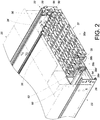
FIG. 2 is a perspective view showing the cable management device in the first embodiment of the present invention located between the object and one of the slide rail assemblies; -
FIG. 3 is a perspective view of the cable management device in the first embodiment of the present invention; -
FIG. 4 is an exploded perspective view of the cable management device, the object, and the slide rail assemblies in the first embodiment of the present invention; -
FIG. 5 is an exploded perspective view of an arm and the supporting member of the cable management device in the first embodiment of the present invention; -
FIG. 6 is an assembled perspective of the arm and the supporting member inFIG. 5 ; -
FIG. 7 is a perspective view of a slide rail assembly in the first embodiment of the present invention; -
FIG. 8 is an enlarged view of the circled area A inFIG. 7 , showing that the first rail of the slide rail assembly includes a disengaging feature; -
FIG. 9 is an enlarged view of the circled area B inFIG. 7 , showing that a locking member of the third rail of the slide rail assembly can be locked to a portion of the second rail; -
FIG. 10 shows a slide rail assembly in the first embodiment of the present invention in a retracted state; -
FIG. 11 shows that the second rail and the third rail of the slide rail assembly inFIG. 10 are simultaneously moved with respect to the first rail in a certain direction; -
FIG. 12 shows that simultaneous movement of the second rail and the third rail inFIG. 11 ends at a predetermined position; -
FIG. 13 shows that the object in the first embodiment of the present invention is mounted on the rack via the slide rail assemblies, and that the cable management device is in a first state; -
FIG. 14 shows that the second rails and the third rails of the slide rail assemblies inFIG. 13 are moved with respect to the first rails in the direction indicated by the arrow inFIG. 11 , that the cable management device is gradually switched to a second state, and that the supporting member is displaced along with the third rail; -
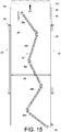
FIG. 15 shows that the second rails inFIG. 14 are further moved with respect to the first rails in the same direction, and that the cable management device is in the second state; -
FIG. 16 shows that, in the second embodiment of the present invention, the first arm of the first set of arms of the cable management device is connected to a rack; and -
FIG. 17 shows that, in the third embodiment of the present invention, the fifth arm of the cable management device is connected to the second rail of a slide rail assembly. - Referring to
FIG. 1 , a rack system includes anobject 20 that is mounted to arack 24 via a firstslide rail assembly 22 and a secondslide rail assembly 23. Theobject 20 may be a piece of electronic equipment, such as a server and/or a power supply. Therack 24 includes a pair offirst posts 26a and a pair ofsecond posts 26b. Each slide rail assembly includes afirst rail 28. Eachfirst rail 28 has two portions respectively arranged with a first bracket 30 (e.g., a front bracket) and a second bracket 32 (e.g., a rear bracket) configured to be mounted to a corresponding one of thefirst posts 26a and a corresponding one of thesecond posts 26b of therack 24 respectively. - As shown in
FIG. 2 , each slide rail assembly further includes asecond rail 34 and athird rail 36. The second rails 34 are mounted with theobject 20. Eachthird rail 36 is movably mounted between the correspondingfirst rail 28 and the correspondingsecond rail 34 to increase the maximum distance for which the correspondingsecond rail 34 can be moved with respect to the correspondingfirst rail 28. In addition, the rack system includes acable management device 37 located behind theobject 20. More specifically, thecable management device 37 includes a first set of arms and a second set of arms. The first set of arms include two arms, e.g., afirst arm 38a and asecond arm 38b. The second set of arms also include two arms, e.g., athird arm 38c and afourth arm 38d. Preferably, thecable management device 37 further includes another arm, e.g., afifth arm 38e. Eacharm cable management feature 35, which may be a groove or cable holder for arranging the cables of theobject 20. As the cable management features 35 are well known in the art, further description is omitted herein for the sake of brevity. - Referring to
FIG. 3 , thefirst arm 38a and thesecond arm 38b of the first set of arms can move with respect to each other, and so can thethird arm 38c and thefourth arm 38d of the second set of arms. Thefifth arm 38e can move with respect to the second set of arms. Thethird arm 38c of the second set of arms is connected to thesecond arm 38b of the first set of arms in such a way that thethird arm 38c and thesecond arm 38b can move with respect to each other. - In this embodiment, each
arm arms pivotal connection element 40, at least one secondpivotal connection element 42, at least one thirdpivotal connection element 44, and at least one fourthpivotal connection element 46. - More specifically, the first end portions E1 of the first arm 38a and the second arm 38b of the first set of arms are pivotally connected by two first pivotal connection elements 40 (e.g., with a first auxiliary base 48 arranged between the first arm 38a and the second arm 38b to facilitate pivotal connection by the first pivotal connection elements 40), the second end portion E2 of the second arm 38b of the first set of arms and the second end portion E2 of the third arm 38c of the second set of arms are pivotally connected by two second pivotal connection elements 42 (e.g., with a second auxiliary base 50 arranged between the second arm 38b and the third arm 38c to facilitate pivotal connection by the second pivotal connection elements 42), the first end portion E1 of the third arm 38c of the second set of arms and the first end portion E1 of the fourth arm 38d of the second set of arms are pivotally connected by two third pivotal connection elements 44 (e.g., with a third auxiliary base 52 arranged between the third arm 38c and the fourth arm 38d to facilitate pivotal connection by the third pivotal connection elements 44), and the second end portion E2 of the fourth arm 38d of the second set of arms and the second end portion E2 of the fifth arm 38e are pivotally connected by two fourth pivotal connection elements 46 (e.g., with a fourth auxiliary base 54 arranged between the fourth arm 38d and the fifth arm 38e to facilitate pivotal connection by the fourth pivotal connection elements 46). The foregoing arrangement makes it possible for the
arms arms auxiliary bases arms - Referring to
FIG. 4 , the second end portion E2 of thefirst arm 38a of the first set of arms is connected to thefirst rail 28 of the first slide rail assembly 22 (e.g., with a fifthpivotal connection element 58 connecting the second end portion E2 of thefirst arm 38a to afirst fitting 56 arranged adjacent to the rear end of thefirst rail 28 of the first slide rail assembly 22), and the first end portion E1 of thefifth arm 38e is connected to the object 20 (e.g., with a sixthpivotal connection element 62 connecting the first end portion E1 of thefifth arm 38e to asecond fitting 60 arranged adjacent to a rear portion of the object 20). - Preferably, the
cable management device 37 further includes a supportingmember 64 arranged between and configured for supporting thearms member 64 may be mounted to thethird rail 36 of one of the firstslide rail assembly 22 and the secondslide rail assembly 23 or to thethird rails 36 of bothslide rail assemblies member 64 are mounted to thethird rails 36 of the twoslide rail assemblies member 64 has a mounting member 66 (as can be seen more clearly inFIG. 6 ) to be detachably hung on a supportingportion 69 adjacent to the rear end of the correspondingthird rail 36 via a mountingfeature 68 such as a hook or peg. It is worth mentioning that, while the supportingmember 64 in this embodiment is "mounted" to thethird rails 36, it is feasible in practice that the supportingmember 64 is "threadedly connected" to thethird rails 36 instead; the present invention has no limitations in this regard. - As shown in
FIG. 5 and FIG. 6 , one of the two arms of the second set of arms (e.g., thethird arm 38c) is pivotally connected to the supportingmember 64 at a position between the two ends of the supportingmember 64. For example, thecable management device 37 further includes a connectingcomponent 70 mounted between the two ends of the supportingmember 64 via two fixingmembers 72, and a portion of thethird arm 38c that is between the first end portion E1 and the second end portion E2 is pivotally connected to the connectingcomponent 70 via ashaft member 74. - Referring to
FIG. 7 and FIG. 8 , thefirst rail 28 of each slide rail assembly (e.g., of the firstslide rail assembly 22 shown in the drawings) includes a disengagingfeature 76. The disengagingfeature 76 may be an additional component connected to thefirst rail 28 by riveting, welding, threaded connection, or the like. Alternatively, the disengagingfeature 76 may be directly formed on thefirst rail 28 by a machining process that provides the disengagingfeature 76 with a specific shape or structure. In this embodiment, the disengagingfeature 76 has a guidingsection 78 such as an inclined or curved surface. Referring toFIG. 9 , the firstslide rail assembly 22 further includes a lockingmember 80 mounted on thethird rail 36 and having a lockingportion 82. On the other hand, thesecond rail 34 has ahole 84 and astop 86 adjacent to thehole 84. The lockingportion 82 of the lockingmember 80 is configured to be locked to thestop 86. - Referring to
FIG. 10 , each slide rail assembly (e.g., the firstslide rail assembly 22 shown in the drawing) can be brought to a certain state, such as a retracted state, in which thesecond rail 34 and thethird rail 36 of the firstslide rail assembly 22 are at a first position P1 with respect to thefirst rail 28. In addition, the lockingmember 80 further includes acontact portion 88, and a portion of the lockingmember 80 that is between thecontact portion 88 and the lockingportion 82 is pivotally connected to thethird rail 36. Preferably, anelastic member 90 applies an elastic force to the lockingmember 80 and has anelastic portion 92 pressed against thecontact portion 88 to keep thecontact portion 88 facing thefirst rail 28. Also, the lockingportion 82 can extend into thehole 84 to stay locked to thestop 86 of thesecond rail 34. - Referring to
FIG. 11 and FIG. 12 , when thesecond rail 34 and thethird rail 36 are moved in a first direction D1 (e.g., an extending direction) with respect to thefirst rail 28 from the first position P1, the lockingportion 82 of the lockingmember 80 is locked to thestop 86 of thesecond rail 34 such that thesecond rail 34 and thethird rail 36 are moved together in the first direction D1. When thesecond rail 34 and thethird rail 36 moving in the first direction D1 are about to reach a predetermined position L, thecontact portion 88 of the lockingmember 80 comes into contact with the guidingsection 78 of the disengagingfeature 76 of thefirst rail 28, and the lockingmember 80 is tilted as a result, thereby releasing the lockingportion 82 of the lockingmember 80 from thestop 86 of thesecond rail 34. In other words, once thethird rail 36 is moved in the first direction D1 with respect to thefirst rail 28 and reaches the predetermined position L, the disengagingfeature 76 terminates the locking relationship between the lockingmember 80 and thestop 86 of thesecond rail 34 by disengaging the lockingportion 82 of the lockingmember 80 from thestop 86. Thethird rail 36 in this state no longer moves along with thesecond rail 34. That is to say, thesecond rail 34 can now be moved further in the first direction D1 with respect to thethird rail 36. - In
FIG. 13 , theslide rail assemblies first arm 38a of thecable management device 37 is pivotally connected to thefirst fitting 56 on thefirst rail 28 of the firstslide rail assembly 22, and the first end portion E1 of thefifth arm 38e of thecable management device 37 is pivotally connected to thesecond fitting 60 on theobject 20. In addition, thecable management device 37 is supported by the supportingmember 64. Moreover, when both sliderail assemblies object 20 is inside therack 24, and thecable management device 37 is in a first state, in which thearms cable management device 37 are close to one another. - Referring to
FIG. 13 andFIG. 14 , when theobject 20 is pulled out of therack 24, thus moving thesecond rails 34 and thethird rails 36 in the first direction D1 (e.g., the extending direction) with respect to thefirst rails 28 from the first position P1, theobject 20 itself is displaced outward of therack 24 in the first direction D1. During the process, thesecond rails 34 and thethird rails 36 can be simultaneously moved in the first direction D1 only until the predetermined position L is reached, and after that, thethird rails 36 can no longer move together with the second rails 34 (refer toFIG. 10, FIG. 11, FIG. 12 , and the related description for the principle of simultaneous movement of thesecond rails 34 and thethird rails 36 and the mechanism of stopping such movement). - More specifically, in the course in which the
second rails 34 and thethird rails 36 are moved in the first direction D1, the supportingmember 64 is displaced in response to thethird rails 36 moving with respect to the first rails 28. Meanwhile, thecable management device 37 is gradually switched from the first state to a second state (e.g., an opened state) in response to thesecond rails 34 moving in the first direction D1 with respect to thefirst rails 28 from the first position P1. Also, thefifth arm 38e is moved in response to the second rails 34 (or the object 20) moving in the first direction D1 with respect to thefirst rails 28 from the first position P1. Thefirst arm 38a and thesecond arm 38b of the first set of arms are opened first because thethird rails 36 move along with the second rails 34. When thesecond rails 34 and thethird rails 36 arrive at the predetermined position L, simultaneous movement of thesecond rails 34 and thethird rails 36 is brought to an end. - Referring to
FIG. 15 , once the simultaneous movement is ended, the second rails 34 (or the object 20) can be further moved in the first direction D1 with respect to thethird rails 36, thereby moving thefifth arm 38e of thecable management device 37 further. Since one of the two arms of the second set of arms (e.g., thethird arm 38c) is pivotally connected to a portion of the supportingmember 64 that is between the two ends of the supportingmember 64, thethird arm 38c and thefourth arm 38d of the second set of arms will be sequentially opened in response to the movement of thefifth arm 38e and then drive thefirst arm 38a and thesecond arm 38b of the first set of arms into movement. When thesecond rails 34 reach a second position P2 with respect to thefirst rails 28 such that the slide rail assemblies are fully extended, thecable management device 37 is in the second state. - It is worth mentioning that, when the
second rails 34 are moved back to the first position P1 with respect to thefirst rails 28 in a second direction (e.g., a retracting direction, which is the opposite direction of the first direction D1) from the second positon P2, thecable management device 37 returns from the second state to the first state (the process of which can be understood by referring toFIG. 13 and therefore will not be described herein). - According to the above, the
cable management device 37 in this embodiment can adapt to slide rail assemblies of a greater total extended length than can the prior art, thanks to the multi-section (e.g., more-than-four-section) cable management arm consisting of thearms cable management device 37 can be opened and closed in stages or in sequence, thus featuring steady opening and closing operations, due to the fact that thesecond rails 34 and thethird rails 36 can move simultaneously for a predetermined distance, and that one of the twoarms -
FIG. 16 shows the second embodiment of the present invention. The second embodiment is different from the first embodiment generally in that the second end portion E2 of thefirst arm 200a of the first set of arms is connected to thesecond post 202 of the rack. For instance, the second end portion E2 of thefirst arm 200a is pivotally connected to athird fitting 204 on thesecond post 202. -
FIG. 17 shows the third embodiment of the present invention. In contrast to thefifth arm 38e in the first embodiment, whose first end portion E1 is connected to theobject 20, thefifth arm 300e of the cable management device in the third embodiment has its first end portion E1 connected to thesecond rail 302 of theslide rail assembly 301. For instance, the first end portion E1 of thefifth arm 300e is pivotally connected to afourth fitting 304 on thesecond rail 302. This configuration is equally capable of switching the cable management device from a first state to a second state in response to thesecond rail 302 moving with respect to thefirst rail 306. - While the present invention has been disclosed through the foregoing preferred embodiments, it should be understood that the embodiments provided herein are not intended to be restrictive of the scope of the invention. The scope of patent protection sought by the applicant is defined by the appended claims.
Claims (15)
- A cable management device (37), comprising:a first set of arms including two arms (38a/200a, 38b) that are movable with respect to each other;characterized in thatthe cable management device (37) further comprises a second set of arms including two arms (38c, 38d) that are movable with respect to each other, the second set of arms being connected to the first set of arms.
- The cable management device (37) as claimed in claim 1, wherein the second set of arms are pivotally connected to the first set of arms.
- The cable management device (37) as claimed in claim 2, wherein one (38b) of the two arms (38a/200a, 38b) of the first set of arms has an end portion (E2) pivotally connected to an end portion (E2) of one (38c) of the two arms (38c, 38d) of the second set of arms.
- The cable management device (37) as claimed in any of claims 1-3, wherein the two arms (38a/200a, 38b) of the first set of arms are pivotally connected to each other.
- The cable management device (37) as claimed in any of claims 1-4, wherein the two arms (38c, 38d) of the second set of arms are pivotally connected to each other.
- The cable management device (37) as claimed in any of claims 1-5, further comprising a supporting member (64) arranged between and configured for supporting the first set of arms and the second set of arms.
- The cable management device (37) as claimed in claim 6, wherein one (38c) of the two arms (38c, 38d) of the second set of arms is pivotally connected to the supporting member (64) at a position between two opposite ends of the supporting member (64).
- The cable management device (37) as claimed in any of claims 1-7, further comprising an additional arm (38e/300e) pivotally connected to the second set of arms.
- A slide rail assembly (22), comprising:a first rail (28);a second rail (34) movable with respect to the first rail (28); andthe cable management device (37) according to any of claims 1-5;wherein one (38a) of the two arms (38a/200a, 38b) of the first set of arms is connected to the first rail (28);wherein the cable management device (37) is switched from a first state to a second state in response to the second rail (34) moving with respect to the first rail (28) from a first position (P1) to a second position (P2).
- The slide rail assembly (22) as claimed in claim 9, wherein the slide rail assembly (22) is adapted for mounting an object (20) to a rack (24); the first rail (28) is mountable to a first post (26a) and a second post (26b/202) of the rack (24) via a first bracket (30) and a second bracket (32) respectively; and the second rail (34) is mountable with the object (20).
- The slide rail assembly (22) as claimed in claim 9 or 10, wherein the cable management device (37) further comprises an additional arm (38e) pivotally connected to one (38d) of the two arms (38c, 38d) of the second set of arms, and the additional arm (38e) is moved in response to the second rail (34) moving with respect to the first rail (28) from the first position (P1) to the second position (P2).
- The slide rail assembly (22) as claimed in claim 11, wherein the first set of arms, the second set of arms, and the additional arm (38e) have a cable management feature (35) where a cable of the object (20) is placeable.
- The slide rail assembly (22) as claimed in any of claims 9-12, further comprising a third rail (36) movably mounted between the first rail (28) and the second rail (34), wherein the cable management device (37) further comprises a supporting member (64) arranged between and configured for supporting the first set of arms and the second set of arms, one (38c) of the two arms (38c, 38d) of the second set of arms is pivotally connected to the supporting member (64) at a position between two opposite ends of the supporting member (64), and the supporting member (64) is displaced in response to the third rail (36) moving with respect to the first rail (28).
- The slide rail assembly (22) as claimed in claim 13, further comprising a locking member (80) mounted on the third rail (36), wherein the locking member (80) is configured to be locked to a portion (86) of the second rail (34) and thereby enable the second rail (34) to move the third rail (36) to a predetermined position (L) in a direction from the first position (P1) to the second position (P2) while the second rail (34) itself is so moved.
- The slide rail assembly (22) as claimed in claim 14, wherein the first rail (28) includes a disengaging feature (76) for disengaging the locking member (80) from the portion (86) of the second rail (34) when the third rail (36) reaches the predetermined position (L).
Applications Claiming Priority (1)
| Application Number | Priority Date | Filing Date | Title |
|---|---|---|---|
| TW105126010A TWI603560B (en) | 2016-08-12 | 2016-08-12 | Slide rail assembly and cable management device thereof |
Publications (2)
| Publication Number | Publication Date |
|---|---|
| EP3282713A1 true EP3282713A1 (en) | 2018-02-14 |
| EP3282713B1 EP3282713B1 (en) | 2018-12-19 |
Family
ID=58701380
Family Applications (1)
| Application Number | Title | Priority Date | Filing Date |
|---|---|---|---|
| EP17167026.8A Active EP3282713B1 (en) | 2016-08-12 | 2017-04-19 | Slide rail assembly and cable management device thereof |
Country Status (4)
| Country | Link |
|---|---|
| US (1) | US10333286B2 (en) |
| EP (1) | EP3282713B1 (en) |
| JP (1) | JP6487485B2 (en) |
| TW (1) | TWI603560B (en) |
Families Citing this family (8)
| Publication number | Priority date | Publication date | Assignee | Title |
|---|---|---|---|---|
| WO2017176879A1 (en) * | 2016-04-08 | 2017-10-12 | Commscope, Inc. Of North Carolina | Cable management assembly |
| TWI600242B (en) * | 2016-08-31 | 2017-09-21 | 川湖科技股份有限公司 | Slide rail assembly and cable management device thereof |
| TWI644607B (en) * | 2018-04-20 | 2018-12-11 | 川湖科技股份有限公司 | Rack system and cable supporting assembly thereof |
| TWI683637B (en) | 2018-07-27 | 2020-02-01 | 川湖科技股份有限公司 | Support assembly and cable management kit |
| CN114914764A (en) * | 2018-08-27 | 2022-08-16 | 莫列斯有限公司 | Hinged busbar assembly and assembly comprising same |
| TWI681703B (en) * | 2019-02-25 | 2020-01-01 | 川湖科技股份有限公司 | Slide rail mechanism and supporting assembly thereof |
| CN112947715B (en) * | 2021-04-28 | 2026-04-03 | 广东远图未来科技有限公司 | server |
| TWI792431B (en) * | 2021-07-21 | 2023-02-11 | 新加坡商鴻運科股份有限公司 | Cable management device |
Citations (5)
| Publication number | Priority date | Publication date | Assignee | Title |
|---|---|---|---|---|
| US7472795B2 (en) | 2003-12-05 | 2009-01-06 | Pentair Electronic Packaging Company | Anti-sag management assembly |
| US7554819B2 (en) | 2004-10-15 | 2009-06-30 | King Slide Works Co., Ltd. | Cable management arm assembly |
| US8387933B2 (en) | 2010-05-31 | 2013-03-05 | Hong Fu Jin Precision Industry (Shenzhen) Co., Ltd. | Cable management apparatus |
| US20140183306A1 (en) * | 2012-12-07 | 2014-07-03 | King Slide Works Co., Ltd. | Cable management arm assembly |
| EP2925103A1 (en) * | 2014-03-27 | 2015-09-30 | King Slide Works Co., Ltd. | Cable management device |
Family Cites Families (27)
| Publication number | Priority date | Publication date | Assignee | Title |
|---|---|---|---|---|
| US2865979A (en) * | 1955-10-14 | 1958-12-23 | Teletype Corp | Extensible cable structure |
| US3219750A (en) * | 1961-11-29 | 1965-11-23 | Adamson Alliance Company Ltd | Electrical power supply connection assemblies for moving machinery |
| US3399909A (en) * | 1966-02-17 | 1968-09-03 | Honeywell Inc | Transmitting apparatus |
| US3647936A (en) * | 1970-04-06 | 1972-03-07 | Iomec | Self-folding cable carrier |
| JPS637927U (en) * | 1986-06-30 | 1988-01-19 | ||
| US5746389A (en) * | 1996-12-18 | 1998-05-05 | E-Systems, Inc. | Cable retractor |
| US6326547B1 (en) * | 1999-11-02 | 2001-12-04 | Compaq Computer Corporation | Cable management system |
| US6600665B2 (en) * | 2001-08-03 | 2003-07-29 | Hewlett-Packard Development Company, L.P. | Cable management arm with trough and breakaway feature |
| JP3716986B2 (en) * | 2002-11-11 | 2005-11-16 | 株式会社椿本チエイン | Guide holders for drawer cables |
| JP3120872U (en) * | 2006-02-06 | 2006-04-20 | 川湖科技股▲分▼有限公司 | Interlocking localization structure of slide rail extension |
| US7746667B1 (en) * | 2007-12-05 | 2010-06-29 | Central Industrial Supply Company | Telescoping support crossbar for a cable management arm |
| JP5067239B2 (en) * | 2008-03-28 | 2012-11-07 | 富士通株式会社 | Cable management device and electronic device device |
| US8231014B2 (en) * | 2008-09-03 | 2012-07-31 | King Slide Works Co., Ltd. | Support slide assembly for a cable management arm |
| TW201134362A (en) * | 2010-03-26 | 2011-10-01 | Hon Hai Prec Ind Co Ltd | Cable management apparatus |
| TW201146144A (en) * | 2010-06-11 | 2011-12-16 | Hon Hai Prec Ind Co Ltd | Cable management apparatus |
| CN103022834A (en) * | 2011-09-27 | 2013-04-03 | 鸿富锦精密工业(深圳)有限公司 | Cable arranging device |
| TWM449433U (en) * | 2012-06-20 | 2013-03-21 | Echostreams Innovative Solutions | Wire organizing holder and its casing segment |
| TWM463183U (en) * | 2013-05-22 | 2013-10-11 | Inventec Corp | Electronic device |
| US9370121B2 (en) * | 2014-03-24 | 2016-06-14 | King Slide Works Co., Ltd. | Cable management device |
| TWM487385U (en) * | 2014-03-31 | 2014-10-01 | Nan Juen Int Co Ltd | Improved structure of wire management device of machine box |
| US20150342081A1 (en) * | 2014-05-22 | 2015-11-26 | Nan Juen International Co., Ltd. | Case cable organizer structure |
| US9383038B2 (en) * | 2014-12-04 | 2016-07-05 | King Slide Works Co., Ltd. | Cable management arm supporting device and mounting assembly thereof |
| US9480182B2 (en) * | 2014-12-30 | 2016-10-25 | King Slide Works Co., Ltd. | Cable management arm |
| US9640961B2 (en) * | 2015-01-28 | 2017-05-02 | King Slide Works Co., Ltd. | Cable management assembly |
| TWI544861B (en) * | 2015-02-17 | 2016-08-01 | The improved structure of the management device | |
| TWI600242B (en) * | 2016-08-31 | 2017-09-21 | 川湖科技股份有限公司 | Slide rail assembly and cable management device thereof |
| TWI616131B (en) * | 2016-08-31 | 2018-02-21 | 川湖科技股份有限公司 | Cable management device |
-
2016
- 2016-08-12 TW TW105126010A patent/TWI603560B/en active
-
2017
- 2017-04-10 US US15/483,002 patent/US10333286B2/en active Active
- 2017-04-19 EP EP17167026.8A patent/EP3282713B1/en active Active
- 2017-04-25 JP JP2017086016A patent/JP6487485B2/en active Active
Patent Citations (5)
| Publication number | Priority date | Publication date | Assignee | Title |
|---|---|---|---|---|
| US7472795B2 (en) | 2003-12-05 | 2009-01-06 | Pentair Electronic Packaging Company | Anti-sag management assembly |
| US7554819B2 (en) | 2004-10-15 | 2009-06-30 | King Slide Works Co., Ltd. | Cable management arm assembly |
| US8387933B2 (en) | 2010-05-31 | 2013-03-05 | Hong Fu Jin Precision Industry (Shenzhen) Co., Ltd. | Cable management apparatus |
| US20140183306A1 (en) * | 2012-12-07 | 2014-07-03 | King Slide Works Co., Ltd. | Cable management arm assembly |
| EP2925103A1 (en) * | 2014-03-27 | 2015-09-30 | King Slide Works Co., Ltd. | Cable management device |
Also Published As
| Publication number | Publication date |
|---|---|
| JP2018026523A (en) | 2018-02-15 |
| JP6487485B2 (en) | 2019-03-20 |
| TW201810846A (en) | 2018-03-16 |
| TWI603560B (en) | 2017-10-21 |
| US10333286B2 (en) | 2019-06-25 |
| US20180048130A1 (en) | 2018-02-15 |
| EP3282713B1 (en) | 2018-12-19 |
Similar Documents
| Publication | Publication Date | Title |
|---|---|---|
| EP3282713B1 (en) | Slide rail assembly and cable management device thereof | |
| EP3291660A1 (en) | Slide rail assembly and cable management device thereof | |
| EP3291659B1 (en) | Slide rail assembly applied to a rack system for mounting an object to a rack | |
| US7472795B2 (en) | Anti-sag management assembly | |
| EP3091825B1 (en) | Cable management device | |
| US9913398B1 (en) | Cable management assembly and cable management device thereof | |
| US9861193B2 (en) | Bracket device | |
| US20110253647A1 (en) | Rack apparatus and cable management structure thereof | |
| US10292301B1 (en) | Coupling assembly and cable management device thereof | |
| US10709033B2 (en) | Coupling assembly and cable management device thereof | |
| US11690193B2 (en) | Support assembly and cable management kit | |
| US20190053396A1 (en) | Cable Management Device and Connecting Assembly for Rack System | |
| TWI524615B (en) | Support device for cable management arm and mounting assembly thereof | |
| US9907400B1 (en) | Retracting mechanism for a movable furniture part | |
| CN107770999B (en) | Slide rail assembly and its cable management device | |
| CN105682403A (en) | Cable management assembly | |
| EP3041329B1 (en) | Cable management arm | |
| EP3076774A1 (en) | Slide rail assembly | |
| EP3030065A1 (en) | Cable management arm supporting device and mounting assembly thereof | |
| EP3051929A1 (en) | Cable management assembly | |
| TW201617542A (en) | Cable management assembly | |
| EP2919480B1 (en) | Cable management arm assembly | |
| CN219268197U (en) | Extensible partition modularized power distribution cabinet | |
| CN112449541B (en) | Connection assembly and wire arranging device thereof | |
| CN107802108B (en) | Return mechanism for a movable furniture part |
Legal Events
| Date | Code | Title | Description |
|---|---|---|---|
| PUAI | Public reference made under article 153(3) epc to a published international application that has entered the european phase |
Free format text: ORIGINAL CODE: 0009012 |
|
| STAA | Information on the status of an ep patent application or granted ep patent |
Free format text: STATUS: THE APPLICATION HAS BEEN PUBLISHED |
|
| AK | Designated contracting states |
Kind code of ref document: A1 Designated state(s): AL AT BE BG CH CY CZ DE DK EE ES FI FR GB GR HR HU IE IS IT LI LT LU LV MC MK MT NL NO PL PT RO RS SE SI SK SM TR |
|
| AX | Request for extension of the european patent |
Extension state: BA ME |
|
| STAA | Information on the status of an ep patent application or granted ep patent |
Free format text: STATUS: REQUEST FOR EXAMINATION WAS MADE |
|
| 17P | Request for examination filed |
Effective date: 20180326 |
|
| RBV | Designated contracting states (corrected) |
Designated state(s): AL AT BE BG CH CY CZ DE DK EE ES FI FR GB GR HR HU IE IS IT LI LT LU LV MC MK MT NL NO PL PT RO RS SE SI SK SM TR |
|
| RIC1 | Information provided on ipc code assigned before grant |
Ipc: H05K 7/14 20060101ALI20180516BHEP Ipc: H04Q 1/06 20060101AFI20180516BHEP |
|
| GRAP | Despatch of communication of intention to grant a patent |
Free format text: ORIGINAL CODE: EPIDOSNIGR1 |
|
| STAA | Information on the status of an ep patent application or granted ep patent |
Free format text: STATUS: GRANT OF PATENT IS INTENDED |
|
| INTG | Intention to grant announced |
Effective date: 20180706 |
|
| GRAS | Grant fee paid |
Free format text: ORIGINAL CODE: EPIDOSNIGR3 |
|
| GRAA | (expected) grant |
Free format text: ORIGINAL CODE: 0009210 |
|
| STAA | Information on the status of an ep patent application or granted ep patent |
Free format text: STATUS: THE PATENT HAS BEEN GRANTED |
|
| AK | Designated contracting states |
Kind code of ref document: B1 Designated state(s): AL AT BE BG CH CY CZ DE DK EE ES FI FR GB GR HR HU IE IS IT LI LT LU LV MC MK MT NL NO PL PT RO RS SE SI SK SM TR |
|
| REG | Reference to a national code |
Ref country code: GB Ref legal event code: FG4D |
|
| REG | Reference to a national code |
Ref country code: CH Ref legal event code: EP |
|
| REG | Reference to a national code |
Ref country code: IE Ref legal event code: FG4D |
|
| REG | Reference to a national code |
Ref country code: DE Ref legal event code: R096 Ref document number: 602017001438 Country of ref document: DE |
|
| REG | Reference to a national code |
Ref country code: AT Ref legal event code: REF Ref document number: 1079982 Country of ref document: AT Kind code of ref document: T Effective date: 20190115 |
|
| REG | Reference to a national code |
Ref country code: NL Ref legal event code: MP Effective date: 20181219 |
|
| PG25 | Lapsed in a contracting state [announced via postgrant information from national office to epo] |
Ref country code: FI Free format text: LAPSE BECAUSE OF FAILURE TO SUBMIT A TRANSLATION OF THE DESCRIPTION OR TO PAY THE FEE WITHIN THE PRESCRIBED TIME-LIMIT Effective date: 20181219 Ref country code: NO Free format text: LAPSE BECAUSE OF FAILURE TO SUBMIT A TRANSLATION OF THE DESCRIPTION OR TO PAY THE FEE WITHIN THE PRESCRIBED TIME-LIMIT Effective date: 20190319 Ref country code: LV Free format text: LAPSE BECAUSE OF FAILURE TO SUBMIT A TRANSLATION OF THE DESCRIPTION OR TO PAY THE FEE WITHIN THE PRESCRIBED TIME-LIMIT Effective date: 20181219 Ref country code: LT Free format text: LAPSE BECAUSE OF FAILURE TO SUBMIT A TRANSLATION OF THE DESCRIPTION OR TO PAY THE FEE WITHIN THE PRESCRIBED TIME-LIMIT Effective date: 20181219 Ref country code: HR Free format text: LAPSE BECAUSE OF FAILURE TO SUBMIT A TRANSLATION OF THE DESCRIPTION OR TO PAY THE FEE WITHIN THE PRESCRIBED TIME-LIMIT Effective date: 20181219 Ref country code: BG Free format text: LAPSE BECAUSE OF FAILURE TO SUBMIT A TRANSLATION OF THE DESCRIPTION OR TO PAY THE FEE WITHIN THE PRESCRIBED TIME-LIMIT Effective date: 20190319 |
|
| REG | Reference to a national code |
Ref country code: LT Ref legal event code: MG4D |
|
| REG | Reference to a national code |
Ref country code: AT Ref legal event code: MK05 Ref document number: 1079982 Country of ref document: AT Kind code of ref document: T Effective date: 20181219 |
|
| PG25 | Lapsed in a contracting state [announced via postgrant information from national office to epo] |
Ref country code: GR Free format text: LAPSE BECAUSE OF FAILURE TO SUBMIT A TRANSLATION OF THE DESCRIPTION OR TO PAY THE FEE WITHIN THE PRESCRIBED TIME-LIMIT Effective date: 20190320 Ref country code: AL Free format text: LAPSE BECAUSE OF FAILURE TO SUBMIT A TRANSLATION OF THE DESCRIPTION OR TO PAY THE FEE WITHIN THE PRESCRIBED TIME-LIMIT Effective date: 20181219 Ref country code: SE Free format text: LAPSE BECAUSE OF FAILURE TO SUBMIT A TRANSLATION OF THE DESCRIPTION OR TO PAY THE FEE WITHIN THE PRESCRIBED TIME-LIMIT Effective date: 20181219 Ref country code: RS Free format text: LAPSE BECAUSE OF FAILURE TO SUBMIT A TRANSLATION OF THE DESCRIPTION OR TO PAY THE FEE WITHIN THE PRESCRIBED TIME-LIMIT Effective date: 20181219 |
|
| PG25 | Lapsed in a contracting state [announced via postgrant information from national office to epo] |
Ref country code: NL Free format text: LAPSE BECAUSE OF FAILURE TO SUBMIT A TRANSLATION OF THE DESCRIPTION OR TO PAY THE FEE WITHIN THE PRESCRIBED TIME-LIMIT Effective date: 20181219 |
|
| PG25 | Lapsed in a contracting state [announced via postgrant information from national office to epo] |
Ref country code: IT Free format text: LAPSE BECAUSE OF FAILURE TO SUBMIT A TRANSLATION OF THE DESCRIPTION OR TO PAY THE FEE WITHIN THE PRESCRIBED TIME-LIMIT Effective date: 20181219 Ref country code: CZ Free format text: LAPSE BECAUSE OF FAILURE TO SUBMIT A TRANSLATION OF THE DESCRIPTION OR TO PAY THE FEE WITHIN THE PRESCRIBED TIME-LIMIT Effective date: 20181219 Ref country code: PT Free format text: LAPSE BECAUSE OF FAILURE TO SUBMIT A TRANSLATION OF THE DESCRIPTION OR TO PAY THE FEE WITHIN THE PRESCRIBED TIME-LIMIT Effective date: 20190419 Ref country code: PL Free format text: LAPSE BECAUSE OF FAILURE TO SUBMIT A TRANSLATION OF THE DESCRIPTION OR TO PAY THE FEE WITHIN THE PRESCRIBED TIME-LIMIT Effective date: 20181219 Ref country code: ES Free format text: LAPSE BECAUSE OF FAILURE TO SUBMIT A TRANSLATION OF THE DESCRIPTION OR TO PAY THE FEE WITHIN THE PRESCRIBED TIME-LIMIT Effective date: 20181219 |
|
| PG25 | Lapsed in a contracting state [announced via postgrant information from national office to epo] |
Ref country code: EE Free format text: LAPSE BECAUSE OF FAILURE TO SUBMIT A TRANSLATION OF THE DESCRIPTION OR TO PAY THE FEE WITHIN THE PRESCRIBED TIME-LIMIT Effective date: 20181219 Ref country code: SM Free format text: LAPSE BECAUSE OF FAILURE TO SUBMIT A TRANSLATION OF THE DESCRIPTION OR TO PAY THE FEE WITHIN THE PRESCRIBED TIME-LIMIT Effective date: 20181219 Ref country code: SK Free format text: LAPSE BECAUSE OF FAILURE TO SUBMIT A TRANSLATION OF THE DESCRIPTION OR TO PAY THE FEE WITHIN THE PRESCRIBED TIME-LIMIT Effective date: 20181219 Ref country code: RO Free format text: LAPSE BECAUSE OF FAILURE TO SUBMIT A TRANSLATION OF THE DESCRIPTION OR TO PAY THE FEE WITHIN THE PRESCRIBED TIME-LIMIT Effective date: 20181219 Ref country code: IS Free format text: LAPSE BECAUSE OF FAILURE TO SUBMIT A TRANSLATION OF THE DESCRIPTION OR TO PAY THE FEE WITHIN THE PRESCRIBED TIME-LIMIT Effective date: 20190419 |
|
| REG | Reference to a national code |
Ref country code: DE Ref legal event code: R097 Ref document number: 602017001438 Country of ref document: DE |
|
| PLBE | No opposition filed within time limit |
Free format text: ORIGINAL CODE: 0009261 |
|
| STAA | Information on the status of an ep patent application or granted ep patent |
Free format text: STATUS: NO OPPOSITION FILED WITHIN TIME LIMIT |
|
| PG25 | Lapsed in a contracting state [announced via postgrant information from national office to epo] |
Ref country code: AT Free format text: LAPSE BECAUSE OF FAILURE TO SUBMIT A TRANSLATION OF THE DESCRIPTION OR TO PAY THE FEE WITHIN THE PRESCRIBED TIME-LIMIT Effective date: 20181219 Ref country code: DK Free format text: LAPSE BECAUSE OF FAILURE TO SUBMIT A TRANSLATION OF THE DESCRIPTION OR TO PAY THE FEE WITHIN THE PRESCRIBED TIME-LIMIT Effective date: 20181219 |
|
| 26N | No opposition filed |
Effective date: 20190920 |
|
| REG | Reference to a national code |
Ref country code: BE Ref legal event code: MM Effective date: 20190430 |
|
| PG25 | Lapsed in a contracting state [announced via postgrant information from national office to epo] |
Ref country code: MC Free format text: LAPSE BECAUSE OF FAILURE TO SUBMIT A TRANSLATION OF THE DESCRIPTION OR TO PAY THE FEE WITHIN THE PRESCRIBED TIME-LIMIT Effective date: 20181219 Ref country code: LU Free format text: LAPSE BECAUSE OF NON-PAYMENT OF DUE FEES Effective date: 20190419 |
|
| PG25 | Lapsed in a contracting state [announced via postgrant information from national office to epo] |
Ref country code: FR Free format text: LAPSE BECAUSE OF NON-PAYMENT OF DUE FEES Effective date: 20190430 Ref country code: SI Free format text: LAPSE BECAUSE OF FAILURE TO SUBMIT A TRANSLATION OF THE DESCRIPTION OR TO PAY THE FEE WITHIN THE PRESCRIBED TIME-LIMIT Effective date: 20181219 Ref country code: BE Free format text: LAPSE BECAUSE OF NON-PAYMENT OF DUE FEES Effective date: 20190430 |
|
| PG25 | Lapsed in a contracting state [announced via postgrant information from national office to epo] |
Ref country code: TR Free format text: LAPSE BECAUSE OF FAILURE TO SUBMIT A TRANSLATION OF THE DESCRIPTION OR TO PAY THE FEE WITHIN THE PRESCRIBED TIME-LIMIT Effective date: 20181219 |
|
| REG | Reference to a national code |
Ref country code: CH Ref legal event code: PL |
|
| PG25 | Lapsed in a contracting state [announced via postgrant information from national office to epo] |
Ref country code: LI Free format text: LAPSE BECAUSE OF NON-PAYMENT OF DUE FEES Effective date: 20200430 Ref country code: CH Free format text: LAPSE BECAUSE OF NON-PAYMENT OF DUE FEES Effective date: 20200430 |
|
| PG25 | Lapsed in a contracting state [announced via postgrant information from national office to epo] |
Ref country code: CY Free format text: LAPSE BECAUSE OF FAILURE TO SUBMIT A TRANSLATION OF THE DESCRIPTION OR TO PAY THE FEE WITHIN THE PRESCRIBED TIME-LIMIT Effective date: 20181219 |
|
| PG25 | Lapsed in a contracting state [announced via postgrant information from national office to epo] |
Ref country code: MT Free format text: LAPSE BECAUSE OF FAILURE TO SUBMIT A TRANSLATION OF THE DESCRIPTION OR TO PAY THE FEE WITHIN THE PRESCRIBED TIME-LIMIT Effective date: 20181219 Ref country code: HU Free format text: LAPSE BECAUSE OF FAILURE TO SUBMIT A TRANSLATION OF THE DESCRIPTION OR TO PAY THE FEE WITHIN THE PRESCRIBED TIME-LIMIT; INVALID AB INITIO Effective date: 20170419 |
|
| PG25 | Lapsed in a contracting state [announced via postgrant information from national office to epo] |
Ref country code: MK Free format text: LAPSE BECAUSE OF FAILURE TO SUBMIT A TRANSLATION OF THE DESCRIPTION OR TO PAY THE FEE WITHIN THE PRESCRIBED TIME-LIMIT Effective date: 20181219 |
|
| PGFP | Annual fee paid to national office [announced via postgrant information from national office to epo] |
Ref country code: DE Payment date: 20250210 Year of fee payment: 9 |
|
| PGFP | Annual fee paid to national office [announced via postgrant information from national office to epo] |
Ref country code: GB Payment date: 20260209 Year of fee payment: 10 |
|
| PGFP | Annual fee paid to national office [announced via postgrant information from national office to epo] |
Ref country code: IE Payment date: 20260206 Year of fee payment: 10 |