EP3282460A1 - Non-contact power transmission coil unit - Google Patents
Non-contact power transmission coil unit Download PDFInfo
- Publication number
- EP3282460A1 EP3282460A1 EP15888458.5A EP15888458A EP3282460A1 EP 3282460 A1 EP3282460 A1 EP 3282460A1 EP 15888458 A EP15888458 A EP 15888458A EP 3282460 A1 EP3282460 A1 EP 3282460A1
- Authority
- EP
- European Patent Office
- Prior art keywords
- coil
- section
- axial direction
- winding wire
- core
- Prior art date
- Legal status (The legal status is an assumption and is not a legal conclusion. Google has not performed a legal analysis and makes no representation as to the accuracy of the status listed.)
- Granted
Links
Images



Classifications
-
- B—PERFORMING OPERATIONS; TRANSPORTING
- B60—VEHICLES IN GENERAL
- B60L—PROPULSION OF ELECTRICALLY-PROPELLED VEHICLES; SUPPLYING ELECTRIC POWER FOR AUXILIARY EQUIPMENT OF ELECTRICALLY-PROPELLED VEHICLES; ELECTRODYNAMIC BRAKE SYSTEMS FOR VEHICLES IN GENERAL; MAGNETIC SUSPENSION OR LEVITATION FOR VEHICLES; MONITORING OPERATING VARIABLES OF ELECTRICALLY-PROPELLED VEHICLES; ELECTRIC SAFETY DEVICES FOR ELECTRICALLY-PROPELLED VEHICLES
- B60L53/00—Methods of charging batteries, specially adapted for electric vehicles; Charging stations or on-board charging equipment therefor; Exchange of energy storage elements in electric vehicles
- B60L53/10—Methods of charging batteries, specially adapted for electric vehicles; Charging stations or on-board charging equipment therefor; Exchange of energy storage elements in electric vehicles characterised by the energy transfer between the charging station and the vehicle
- B60L53/12—Inductive energy transfer
-
- B—PERFORMING OPERATIONS; TRANSPORTING
- B60—VEHICLES IN GENERAL
- B60L—PROPULSION OF ELECTRICALLY-PROPELLED VEHICLES; SUPPLYING ELECTRIC POWER FOR AUXILIARY EQUIPMENT OF ELECTRICALLY-PROPELLED VEHICLES; ELECTRODYNAMIC BRAKE SYSTEMS FOR VEHICLES IN GENERAL; MAGNETIC SUSPENSION OR LEVITATION FOR VEHICLES; MONITORING OPERATING VARIABLES OF ELECTRICALLY-PROPELLED VEHICLES; ELECTRIC SAFETY DEVICES FOR ELECTRICALLY-PROPELLED VEHICLES
- B60L5/00—Current collectors for power supply lines of electrically-propelled vehicles
-
- H—ELECTRICITY
- H01—ELECTRIC ELEMENTS
- H01F—MAGNETS; INDUCTANCES; TRANSFORMERS; SELECTION OF MATERIALS FOR THEIR MAGNETIC PROPERTIES
- H01F27/00—Details of transformers or inductances, in general
- H01F27/08—Cooling; Ventilating
-
- H—ELECTRICITY
- H01—ELECTRIC ELEMENTS
- H01F—MAGNETS; INDUCTANCES; TRANSFORMERS; SELECTION OF MATERIALS FOR THEIR MAGNETIC PROPERTIES
- H01F27/00—Details of transformers or inductances, in general
- H01F27/24—Magnetic cores
-
- H—ELECTRICITY
- H01—ELECTRIC ELEMENTS
- H01F—MAGNETS; INDUCTANCES; TRANSFORMERS; SELECTION OF MATERIALS FOR THEIR MAGNETIC PROPERTIES
- H01F27/00—Details of transformers or inductances, in general
- H01F27/28—Coils; Windings; Conductive connections
- H01F27/2823—Wires
-
- H—ELECTRICITY
- H01—ELECTRIC ELEMENTS
- H01F—MAGNETS; INDUCTANCES; TRANSFORMERS; SELECTION OF MATERIALS FOR THEIR MAGNETIC PROPERTIES
- H01F27/00—Details of transformers or inductances, in general
- H01F27/28—Coils; Windings; Conductive connections
- H01F27/2876—Cooling
-
- H—ELECTRICITY
- H01—ELECTRIC ELEMENTS
- H01F—MAGNETS; INDUCTANCES; TRANSFORMERS; SELECTION OF MATERIALS FOR THEIR MAGNETIC PROPERTIES
- H01F27/00—Details of transformers or inductances, in general
- H01F27/28—Coils; Windings; Conductive connections
- H01F27/30—Fastening or clamping coils, windings, or parts thereof together; Fastening or mounting coils or windings on core, casing, or other support
- H01F27/306—Fastening or mounting coils or windings on core, casing or other support
-
- H—ELECTRICITY
- H01—ELECTRIC ELEMENTS
- H01F—MAGNETS; INDUCTANCES; TRANSFORMERS; SELECTION OF MATERIALS FOR THEIR MAGNETIC PROPERTIES
- H01F38/00—Adaptations of transformers or inductances for specific applications or functions
- H01F38/14—Inductive couplings
-
- Y—GENERAL TAGGING OF NEW TECHNOLOGICAL DEVELOPMENTS; GENERAL TAGGING OF CROSS-SECTIONAL TECHNOLOGIES SPANNING OVER SEVERAL SECTIONS OF THE IPC; TECHNICAL SUBJECTS COVERED BY FORMER USPC CROSS-REFERENCE ART COLLECTIONS [XRACs] AND DIGESTS
- Y02—TECHNOLOGIES OR APPLICATIONS FOR MITIGATION OR ADAPTATION AGAINST CLIMATE CHANGE
- Y02T—CLIMATE CHANGE MITIGATION TECHNOLOGIES RELATED TO TRANSPORTATION
- Y02T10/00—Road transport of goods or passengers
- Y02T10/60—Other road transportation technologies with climate change mitigation effect
- Y02T10/70—Energy storage systems for electromobility, e.g. batteries
-
- Y—GENERAL TAGGING OF NEW TECHNOLOGICAL DEVELOPMENTS; GENERAL TAGGING OF CROSS-SECTIONAL TECHNOLOGIES SPANNING OVER SEVERAL SECTIONS OF THE IPC; TECHNICAL SUBJECTS COVERED BY FORMER USPC CROSS-REFERENCE ART COLLECTIONS [XRACs] AND DIGESTS
- Y02—TECHNOLOGIES OR APPLICATIONS FOR MITIGATION OR ADAPTATION AGAINST CLIMATE CHANGE
- Y02T—CLIMATE CHANGE MITIGATION TECHNOLOGIES RELATED TO TRANSPORTATION
- Y02T10/00—Road transport of goods or passengers
- Y02T10/60—Other road transportation technologies with climate change mitigation effect
- Y02T10/7072—Electromobility specific charging systems or methods for batteries, ultracapacitors, supercapacitors or double-layer capacitors
-
- Y—GENERAL TAGGING OF NEW TECHNOLOGICAL DEVELOPMENTS; GENERAL TAGGING OF CROSS-SECTIONAL TECHNOLOGIES SPANNING OVER SEVERAL SECTIONS OF THE IPC; TECHNICAL SUBJECTS COVERED BY FORMER USPC CROSS-REFERENCE ART COLLECTIONS [XRACs] AND DIGESTS
- Y02—TECHNOLOGIES OR APPLICATIONS FOR MITIGATION OR ADAPTATION AGAINST CLIMATE CHANGE
- Y02T—CLIMATE CHANGE MITIGATION TECHNOLOGIES RELATED TO TRANSPORTATION
- Y02T90/00—Enabling technologies or technologies with a potential or indirect contribution to GHG emissions mitigation
- Y02T90/10—Technologies relating to charging of electric vehicles
- Y02T90/14—Plug-in electric vehicles
Definitions
- the present invention relates to a coil unit for contactless power transmission.
- WO2013/183665 discloses a contactless power supply transformer that includes a pair of magnetic pole portions, and an inter-magnetic-pole core portion provided between the pair of magnetic pole portions.
- the inter-magnetic-pole core portion is formed by alternately disposing a ferrite member and a thermal conductor. Heat generated due to iron loss of the inter-magnetic-pole core portion can be dissipated to the outside through the thermal conductors.
- the thermal conductor is made of aluminum, and thus the amount of magnetic flux linkage with a coil decreases, and the electromagnetic performance (such as the inductance, and the coupling coefficient) of the coil may be degraded, as compared with the case where the entire inter-magnetic-pole core portion is made of a ferrite member.
- the present invention has been made in view of the above-mentioned problem, and an object of the present invention is to improve the heat dissipation performance of the coil while suppressing degradation of the electromagnetic performance of the coil.
- An aspect of the present invention provides a coil unit for contactless power transmission includes a non-circular flat coil; a core member made of a magnetic material; and a thermal conductor that has a higher thermal conductivity than the core member.
- the coil has a corner section and a non-corner section in a coil axial direction view, and the core member and the thermal conductor are disposed to face the non-corner section and the corner section, respectively in a coil axial direction.
- a thermal conductor is disposed to face the corner section of the coil, and thus the thermal conductor can be in close proximity to the coil while suppressing the effect on the amount of magnetic flux passing through the core member. Since the thermal conductor has a higher thermal conductivity than the core member, the heat of the coil can be introduced to the outside efficiently. Thus, the heat dissipation performance of the coil unit can be improved while suppressing degradation of the electromagnetic performance of the coil.
- a coil unit U1 for contactless power supply is a device that supplies power in a contactless manner to an electric vehicle stopped at a predetermined position.
- the coil unit U1 supplies power to an in-vehicle battery or the like via a coil unit for power reception mounted in an electric vehicle.
- the coil unit U1 includes a coil section 10 having a coil axis X approximately parallel to a vertical direction, a core section 20 that supports the coil section 10, and a support section 30 that supports the coil section 10 and the core section 20 on the ground.
- the entire coil unit U1 is covered with a unit cover 40 installed in the ground.
- the coil section 10 includes a flat coil 11 having a thickness in the coil axial direction.
- the coil 11 is approximately plate-shaped as a whole, and has a major surface 11a perpendicular to the coil axis X.
- a winding wire 13 of the coil 11 is a litz wire wound in a rectangular spiral form in a coil axial direction view, and occupies an approximately rectangular annular area in a coil axial direction view.
- the coil 11 has 4 corner sections C corresponding to the corners of the rectangular annular area, and 4 non-corner sections NC corresponding to the sides of the rectangular annular area.
- Each of the corner sections C includes a portion (hereinafter, a local maximum curvature section) 13ar that has a local maximum curvature in a coil axial direction view, out of the innermost circumferential winding wire 13a, and a portion positioned between one side boundary surface P1 and the other side boundary surface P2 outwardly of the local maximum curvature section 13ar out of winding wires 13b to 13e other than the innermost circumferential winding wire 13a.
- the local maximum curvature section 13ar of the innermost circumferential winding wire 13a is a portion of the winding wire 13a, having a curvature greater than the average value (hereinafter the curvature average value) of the curvature of the circumference of the winding wire 13a.
- the one side boundary surface P1 is a virtual plane surface that passes through one end of the local maximum curvature section 13ar and is perpendicular to the extension direction of the winding wire 13a at the end
- the other side boundary surface P2 is a virtual plane surface that passes through the other end of the local maximum curvature section 13ar and is perpendicular to the extension direction of the winding wire 13a at the other end.
- the corner sections C in this embodiment also include a local maximum curvature section 13er of the outermost circumferential winding wire 13e.
- non-corner sections NC are the portions other than the corner sections C. Therefore, the curvature of the innermost circumferential winding wire 13a everywhere forming each non-corner section NC is less than or equal to the above-mentioned curvature average value.
- each non-corner section NC is an approximately linear portion that is interposed between adjacent corner sections C.
- the core section 20 is provided downwardly (one side in the coil axial direction) of the coil section 10, approximately parallel to the major surface 11a of the coil 11.
- the core section 20 has an approximately rectangular plate-like shape having a thickness in the coil axial direction, and the 4 sides are approximately parallel to respective extending directions of the non-corner sections NC of the coil 11 in a coil axial direction view.
- the core section 20 includes a ferrite core 21 (a magnetic material core member), and a core case 23 that houses the ferrite core 21.
- the ferrite core 21 forms a magnetic material layer parallel to the major surface 11a of the coil 11.
- the coil 11 is supported by the upper surface of the core case 23.
- the core case 23 includes a resin tray 25 having an approximately rectangular outer shape in a coil axial direction view, and an approximately rectangular plate-shaped resin lid 27 that covers an upper opening of the tray 25.
- the tray 25 includes an approximately rectangular plate-shaped bottom plate 25a, and a circumferential wall section 25b provided perpendicularly to the circumferential edge of the bottom plate 25a.
- the circumferential edge of the lid 27 is fastened to the circumferential wall section 25b of the tray 25 by a non-magnetic material fastening tool or the like.
- the upper surface of the lid 27 is in contact with the winding wire 13 of the coil 11, and a housing space S for housing the ferrite core 21 is formed between the tray 25 and the lid 27.
- the bottom plate 25a of the tray 25 is provided with openings 25c at four corners corresponding to the corner sections C of the coil 11, and an upper end 31 a of a later-described support member 31 is inserted in each of the openings 25c.
- the ferrite core 21 includes multiple ferrite tiles 29 (magnetic material core members) with which the above-mentioned housing space S is covered.
- Each ferrite tile 29 has a rectangular parallelepiped shape with the approximately square bottom surface. It is to be noted that some ferrite tiles 29 positioned inwardly of the innermost circumferential winding wire 13a in a coil axial direction view may be thinned as needed according to a capacity required for the coil unit U1.
- the multiple ferrite tiles 29 are disposed to be positioned immediately below one the winding wires 13a to 13e (to be overlapped with the winding wires 13a to 13e in projection in a coil axial direction) that form at least the non-corner sections NC of the coil 11.
- the upper surface of the ferrite core 21 is at a position facing the non-corner sections NC of the coil 11 in a coil axial direction with the lid 27 of the core case 23 interposed therebetween.
- the support section 30 is provided below the coil section 10, and supports the coil section 10 and the core section 20.
- the support section 30 consists of aluminum support members 31 (thermal conductors) provided at four corners of the core section 20, and a base plate 33 connected to the lower end of the support members 31 in a heat transferable manner.
- the base plate 33 is made of, for instance, metal such as aluminum, and is fastened to the ground by a fastening member such as an anchor bolt.
- Each of the support members 31 has a prism-like shape, and the upper end (heat input section of thermal conductor) 31a is inserted in an opening 25c of the tray 25 of the core case 23.
- the ferrite core 21 that forms a magnetic material layer and the upper ends 31a of the support member 31 are disposed in the same layer in close proximity to each other in the extending direction of the magnetic material layer. In other words, the ferrite core 21 at the positions corresponding to the corner sections C of the coil 11 is replaced by the support members 31.
- the upper ends 31a of the support members 31 are at positions facing the corner sections C of the coil 11 in a coil axial direction with the lid 27 of the core case 23 interposed therebetween. That is, the upper ends 31a are disposed to be positioned immediately below one the winding wires 13a to 13e (to be overlapped with the winding wires 13a to 13e in projection in a coil axial direction) that form at least the corner sections C of the coil 11. Particularly in this embodiment, at least part of the upper ends 31a of the support member 31 is disposed to be overlapped with the outermost circumferential winding wire 13e that forms the corner sections C in a coil axial direction view.
- the upper surface of the upper ends 31a is approximately flush with the upper surface of the ferrite tiles 29 disposed immediately below the winding wires 13a to 13e forming the non-corner sections NC, and is in contact with the lower surface (inner surface) of the lid 27 of the core case 23. Also, a lateral surface of the upper ends 31a is in contact with a lateral surface of the ferrite tiles 29 in the core case 23.
- Heat can be transferred between the support members 31 and the coil 11 via a contact surface between the lid 27 of the core case 23 and the winding wire 13, via a contact surface between the lid 27 and the upper ends 31a of the support members 31, and via the lid 27. Also, heat can be transferred between the support members 31 and the ferrite core 21 via a contact surface between the upper ends 31 a of the support members 31 and the ferrite tiles 29. Therefore, heat generated in the coil section 10 and the core section 20 is dissipated to the outside (such as the ground) via the support members 31 and the base plate 33.
- Each support members 31 is made of aluminum and has a higher thermal conductivity than the ferrite tiles 29, in short, the ferrite core 21, and thus serves as an excellent thermal conductor. Also, the lower surface of the base plate 33 is in contact with the ground at a large area, and thus serves as an excellent heat dissipation surface.
- Fig. 2 illustrates a magnetic flux density distribution and images (arrows) of typical lines of magnetic force in a vicinity area (the lower surface level of the coil 11) in a coil axial direction of the coil 11. It is to be noted that in Fig. 2 , the darker the color of an area, the higher the magnetic flux density. As indicated by arrows in Fig. 2 , in the areas corresponding to the corner sections C of the coil 11, the number of lines of magnetic force per unit volume of the ferrite core 21 is smaller at a more outer position (at a position more separated from the coil axis X).
- a low magnetic flux density area (for instance, an area LD) is likely to occur in corner section vicinity areas CP than in non-corner section vicinity areas NCP.
- the winding wire 13 generates heat due to its resistance loss (copper loss) during a contactless power supply operation, thus the temperature of the coil 11 increases.
- each support member 31 is disposed to face a corner section C of the coil 11, and thus the support member 31 which is a thermal conductor can be in close proximity to the winding wire 13 which is a heating element while suppressing the effect on the amount of magnetic flux passing through the ferrite core 21. Also, since the support member 31 has a higher thermal conductivity than the ferrite core 21, the heat of the winding wire 13 can be introduced to the outside efficiently. Thus, the heat dissipation performance of the coil unit U1 can be improved while suppressing degradation of the electromagnetic performance of the coil 11.
- the magnetic flux density distribution in a peripheral area of the coil 11 tends to be lower at a portion more outwardly of the areas corresponding to the corner sections C of the coil 11.
- at least part of the support members 31 is disposed to be overlapped with the outermost circumferential winding wire 13e in a coil axial direction view. Consequently, the support members 31 are disposed in an area having a lower magnetic flux density, and thus it is possible to suppress degradation of the electromagnetic performance of the coil 11 more reliably.
- the ferrite tiles 29 at the positions corresponding to the corner sections C of the coil 11 are replaced by the aluminum support members 31 that have a higher thermal conductivity than the ferrite core 21. For this reason, the heat dissipation performance is improved because the heat resistance decreases on the way from the winding wire 13 of the coil 11 to a heat dissipation surface, as compared with the case where the ferrite tiles 29 are left at the above-mentioned positions.
- the support members 31 are made of aluminum in this embodiment, the heat dissipation performance is improved because the heat resistance decreases on the way from the winding wire 13 of the coil 11 to a heat dissipation surface, as compared with the case where the support members 31 are made of, for instance, resin.
- the support members 31 are connected to the base plate 33 fastened to the ground in a heat transferable manner, and thus the heat of the winding wire 13 can be efficiently dissipated via the base plate 33.
- the winding wire 13 of the coil 11 is wound in a rectangular spiral form in this embodiment, a larger coil area for each turn (area surrounded by the winding wire 13) can be provided in a rectangular area where vertical and horizontal dimensions are restricted in a plan view, and thus the inductance of the coil 11 can be increased.
- the 4 non-corner sections NC are approximately linear in the coil 11 of this embodiment, it is possible to provide a large difference between the curvature of the innermost circumferential winding wire 13a and the curvature average value of the winding wire 13a at each corner section C. Therefore, the tendency of relative decrease in magnetic flux density is more obvious in the corner section vicinity areas CP. Consequently, it is possible to suppress the effect made on the electromagnetic performance of the coil 11 by the support members 31 disposed to face the corner sections C.
- the coil unit U2 differs from the coil unit U1 according to the first embodiment in that an upper end 31Aa of a support member 31A (thermal conductor) is positioned outwardly of the innermost circumferential winding wire 13a in a coil axial direction view.
- the support members 31A in this embodiment are provided at the four corners of the core section 20.
- the support members 31A each have a prism-like shape, and the upper ends 31Aa thereof are inserted in the openings 25c provided at the four corners of the bottom plate 25a of the tray 25 of the core case 23.
- the upper ends 31Aa face the corner sections C of the coil 11 in a coil axial direction with the lid 27 of the core case 23 interposed therebetween.
- the upper ends 31Aa of the support members 31A are disposed to be positioned immediately below the outermost circumferential winding wire 13e (to be overlapped with the winding wire 13e in projection in a coil axial direction) that form at least the corner sections C of the coil 11.
- the upper ends 31Aa are positioned outwardly of the innermost circumferential winding wire 13a of the coil 11 in a coil axial direction view.
- innermost ends 31AP of the upper ends 31Aa are positioned outwardly in a coil axial direction view of the innermost circumferential winding wire 13a that forms the corner sections C of the coil 11.
- the upper ends 31Aa of the support members 31A are not positioned immediately below the innermost circumferential winding wire 13a (not overlapped with the winding wire 13a in projection in a coil axial direction), and the support members 31A are not present in portions CP1 (see Fig. 2 ) inwardly (closer to the coil axis X) of the corner section vicinity areas CP.
- ferrite tiles 29a are disposed in the portions CP1.
- the ferrite core 21 can be disposed in high magnetic flux density areas which are formed in the portions CP1 inwardly of the corner section vicinity areas CP. Consequently, it is possible to further suppress degradation of the electromagnetic performance of the coil 11.
- the coil unit U3 differs from the coil units U1, U2 according to the first and second embodiments mainly in the following two points.
- the first point is that multiple first support members 31B are disposed to face one non-corner section NC, and second ferrite tiles 29d (magnetic material core members) extending from the inside to the outside of the coil 11 are disposed between these first support members 31B.
- the second point is that multiple second support members 31C (thermal conductors) are disposed to face one corner section C, and third ferrite tiles 29e (magnetic material members) extending from the inside to the outside of the coil 11 are disposed between these second support members 31C.
- the ferrite core 21 in this embodiment includes multiple first ferrite tiles 29c with which the housing space S of the core case 23 is covered, the second ferrite tiles 29d, and the third ferrite tiles 29e.
- the first ferrite tiles 29c each have a rectangular parallelepiped shape with the approximately square bottom surface, and a rectangular area inwardly of the innermost circumferential winding wire 13a in a coil axial direction view is fully covered with the first ferrite tiles 29c.
- the second ferrite tiles 29d are disposed at predetermined intervals in the extending direction of each non-corner section NC of the coil 11 so as to be positioned immediately below the winding wire 13 (be overlapped with the winding wire 13 in projection in a coil axial direction) that forms the non-corner sections NC of the coil 11.
- the second ferrite tiles 29d each have a rectangular parallelepiped shape with the approximately rectangular bottom surface, and are disposed so as to cross the winding wire 13 that forms the non-corner sections NC, in a coil axial direction view.
- each second ferrite tile 29d is in contact with one of the first ferrite tiles 29c, and a magnetic path extending from the inside to the outside of a non-corner section NC in a coil axial direction view is formed.
- the third ferrite tiles 29e are disposed so as to be positioned immediately below the winding wire 13 (be overlapped with the winding wire 13 in projection in a coil axial direction) that forms the corner sections C of the coil 11.
- the third ferrite tiles 29e each have a hexagonal prism shape with the elongated hexagonal bottom surface, and are disposed so as to cross the winding wire 13 that forms the corner sections C in a coil axial direction view, or to extend along the curvature radius direction of the winding wire 13 that forms the corner sections C.
- each third ferrite tile 29e is in contact with the first or second ferrite tile 29c, 29d, and a magnetic path extending radially from the inside to the outside of a corner section C in a coil axial direction view is formed.
- a magnetic path extending radially from the inside to the outside of a corner section C in a coil axial direction view is formed.
- triangular spaces between the third ferrite tile 29e and the two closest second ferrite tiles 29d in a coil axial direction view are formed.
- each third ferrite tile 29e is at a position facing a corner section C of the coil 11 in a coil axial direction with the lid 27 of the core case 23 interposed therebetween.
- the upper surface of each second ferrite tile 29d is at a position facing a non-corner section NC of the coil 11 in a coil axial direction with the lid 27 of the core case 23 interposed therebetween.
- openings 25c1, 25c2 are provided at positions corresponding to the above-mentioned spaces that are formed between the second ferrite tiles 29d and between the second ferrite tile 29d and the third ferrite tile 29e.
- the later-described upper ends 31Ba of the first support members 31B are each inserted in the first opening 25c1 corresponding to a space between the second ferrite tiles 29d.
- the later-described upper ends 31Ca of the second support member 31C are each inserted in the opening 25c2 corresponding to a space between the second ferrite tile 29d and the third ferrite tile 29e.
- the support section 30 includes multiple aluminum first support members 31B and second support members 31C, and the base plate 33 connected to the lower ends of the first and second support members 31B, 31C in a heat transferable manner.
- Each side of the core section 20 is provided with 3 sets of the first support member 31B, and the core section 20 is provided with totally 9 sets of the first support member 31B.
- Each first support member 31B has a quadrangular prism shape, and the upper end 31Ba thereof is inserted in a first opening 25c1 of the tray 25.
- each first support member 31B faces a non-corner section NC of the coil 11 in a coil axial direction with the lid 27 of the core case 23 interposed therebetween, and is disposed so as to be positioned immediately below the winding wire 13 (be overlapped with the winding wire 13 in projection in a coil axial direction) that forms at least the non-corner sections NC.
- the upper surface of the upper end 31Ba is approximately flush with the upper surface of the second ferrite tiles 29d, and is in contact with the lower surface (inner surface) of the lid 27 of the core case 23.
- a lateral surface of the upper end 31Ba is in contact with lateral surfaces of the first and second ferrite tiles 29c, 29d.
- each of the four corners of the core section 20 is provided with 2 sets of the second support member 31C.
- Each second support member 31C has a triangular prism shape, and the upper end 31Ca is inserted in a second opening 25c2 of the tray 25.
- each second support member 31C faces a corner section C of the coil 11 in a coil axial direction with the lid 27 of the core case 23 interposed therebetween, and is disposed so as to be positioned immediately below the outermost circumferential winding wire 13e (be overlapped with the winding wire 13e in projection in a coil axial direction) that forms at least the corner sections C.
- the upper surface of the upper end 31Ca is approximately flush with the upper surfaces of the second and third ferrite tiles 29d, 29e, and is in contact with the lower surface (inner surface) of the lid 27 of the core case 23.
- a lateral surface of the upper end 31 Ca is in contact with lateral surfaces of the second and third ferrite tiles 29d, 29e.
- heat can be transferred between the first and second support members 31B, 31C and the coil 11 via a contact surface between the lid 27 of the core case 23 and the winding wire 13, a contact surface between the lid 27 and the upper ends 31Ba, 31Ca of the first and second support members 31B, 31C, and via the lid 27.
- heat can be transferred between the first support members 31B and the ferrite core 21 via a contact surface between the upper ends 31Ba of the first support members 31B and the first and second ferrite tiles 29c, 29d.
- heat can be transferred between the second support members 31C and the ferrite core 21 via a contact surface between the upper ends 31 Ca of the second support members 31C and the second and third ferrite tiles 29d, 29e. Therefore, heat generated in the coil section 10 and the core section 20 is dissipated to the outside (such as the ground) via the first and second support members 31B, 31C and the base plate 33.
- multiple second support members 31C are disposed to face a corner section C of the coil 11, and the third ferrite tile 29e extending from the inside to the outside of the coil 11 is disposed between those second support members 31C. Therefore, in an area corresponding to each corner section C, a magnetic path along the flow of magnetic flux can be formed with less magnetic materials, and a large range of the second support member 31C which is a good thermal conductor can be provided. Thus, the heat dissipation performance of the coil unit U3 can be improved while suppressing degradation of the electromagnetic performance of the coil 11.
- first support members 31B are disposed to face a non-corner section NC of the coil 11, and the second ferrite tile 29d extending from the inside to the outside of the coil 11 is disposed between those first support members 31B. Therefore, in an area corresponding to each non-corner section NC, a magnetic path along the flow of magnetic flux can be formed with less magnetic materials, and a large range of the first support member 31B which is a good thermal conductor can be provided.
- the corner sections C of the flat coil 11 may take various forms according to an inductance required for the coil and an acceptable curvature (a minimum bending radius) of the winding wire 13. For instance, as illustrated in (a) of Fig. 5 , the area surrounded by the winding wire 13 may be maximized for each turn by bending all winding wires 13 from the innermost to the outermost with a minimum bending radius in the predetermined corner areas.
- each corner section C includes a local maximum curvature section 13ar of the innermost circumferential winding wire 13a, and a portion that is positioned between one side boundary surface P1 and the other side boundary surface P2 and is outwardly of the local maximum curvature section 13ar in the other winding wires 13b to 13e.
- the corner section C includes a local maximum curvature section 13er of the outermost circumferential winding wire 13e.
- each non-corner section NC is a portion that is interposed by the boundary surfaces P1, P2 between adjacent corner sections C, and is formed of an approximately linear winding wire 13 in the coil 11 in (a) of Fig. 5 .
- the corner section C includes a portion positioned between one side boundary surface P1 and the other side boundary surface P2 that pass through a bending point of the innermost circumferential winding wire 13a.
- the non-corner section NC includes a portion that is interposed by the boundary surfaces P1, P2 between adjacent corner sections C, and is formed of an approximately linear winding wire 13.
- each corner section C includes the local maximum curvature section 13ar of the innermost circumferential winding wire 13a, and a portion that is positioned between one side boundary surface P1 and the other side boundary surface P2 and is outwardly of the local maximum curvature section 13ar in the other winding wires 13b to 13e.
- the corner section C includes part of the local maximum curvature section 13er of the outermost circumferential winding wire 13e.
- the innermost circumferential winding wire may be circular in a coil axial direction view.
- one of the winding wires other than the circular winding wire, and the one not circular and is positioned in the innermost in a coil axial direction view is regarded as the innermost circumferential winding wire, and the corner section C and the non-corner section NC may be defined.
- the coil units U1, U2, U3 in the above-mentioned embodiments are coil units for power supply
- the present invention is also applicable to a coil unit for power reception mounted in an electric vehicle.
- the coil unit for power reception can be constituted by a coil section, a core section provided above the coil section, and a support section that supports the coil section and the core section by the lower surface of a vehicle body.
- the support section can be constituted by a support member inserted into a core case (thermal conductor), and an aluminum magnetic shield, connected to the support member and fastened to the lower surface of a vehicle body.
- heat generated in the coil section and the core section is dissipated to the outside (such as air in the surroundings of the magnetic shield) via the support member and the magnetic shield.
- the support members 31, 31A, 31B, 31C are adopted as the support members 31, 31A, 31B, 31C.
- the material of the support member is not particularly limited, and a member having a higher thermal conductivity than the ferrite core 21 can be adopted. From the viewpoint of suppressing heat generation at the time of energization, it is desirable that the member have low hysteresis loss and Eddy current loss. However, it is not necessary that the member is necessarily a non-magnetic material. It is to be noted that an aluminum material is most suitable from the aspect of cost.
- the coil 11 of the above-mentioned embodiments has an approximately rectangular annular shape in a coil axial direction view
- the shape of the coil is not particularly limited, and the present invention is applicable when the shape is non-circular.
- non-circular shape include a sector shape, a semi-circular shape, and a polygonal shape.
- a corner section C is formed in each portion corresponding to a vertex
- a non-corner section NC is formed in each portion corresponding to a side.
- a corner section C is formed in each portion corresponding to an intersection point between a radius and an arc, the central angle, and a non-corner section NC is formed in each portion corresponding to a radius, an arc.
- a corner section C is formed in each portion corresponding to both ends of a chord, and a non-corner section NC is formed in each portion corresponding to a chord, an arc. Therefore, the magnetic flux density distribution in a peripheral area of a non-circular coil becomes non-uniform, and like the case of the rectangular annular coil, an area having a lower magnetic flux density is likely to occur in a corner section vicinity area.
- the thermal conductor is disposed to face a corner section C, and thus the thermal conductor can be disposed in close proximity to the winding wire which is a heating element, while suppressing the effect on the amount of magnetic flux passing through the core member.
- the coil section 10 has the single coil 11 in the above-mentioned embodiments, the coil section may include two or more coils disposed side by side in the perpendicular direction (horizontal direction) to the coil axis.
- the wire of the coil 11 in the above-mentioned embodiments is wound 5 turns from the innermost to the outermost, the number of winding is not particularly limited, and may be less than 5 turns or more than 5 turns.
- the winding wire 13 of the coil 11 is wound from the innermost to the outermost without being overlapped in a coil axial direction.
- the winding wire may be wound with two turns overlapped in a coil axial direction.
- the electrical insulation performance is ensured by interposing the lid 27 of the core case 23 between the upper ends 31a, 31Aa, 31Ba, 31Ca of the support members 31, 31A, 31B, 31C, and the coil 11.
- the upper surfaces of the support members 31, 31A, 31B, 31C may be in direct contact with the winding wire 13. This causes the heat dissipation performance to be further improved.
- the ferrite tiles 29 facing the corner sections C of the coil 11 are replaced by the support members 31, 31A, 31C, which are thereby in close proximity to the coil 11.
- the support members 31, 31A, 31C may be disposed in close proximity to the coil by reducing the thickness of the ferrite tile 29 (reducing the height in a coil axial direction).
- a coil unit for contactless power transmission can be provided.
Landscapes
- Engineering & Computer Science (AREA)
- Power Engineering (AREA)
- Transportation (AREA)
- Mechanical Engineering (AREA)
- Current-Collector Devices For Electrically Propelled Vehicles (AREA)
- Electric Propulsion And Braking For Vehicles (AREA)
- Coils Of Transformers For General Uses (AREA)
- Coils Or Transformers For Communication (AREA)
- Transformer Cooling (AREA)
Abstract
Description
- The present invention relates to a coil unit for contactless power transmission.
- International Publication No.
WO2013/183665 discloses a contactless power supply transformer that includes a pair of magnetic pole portions, and an inter-magnetic-pole core portion provided between the pair of magnetic pole portions. The inter-magnetic-pole core portion is formed by alternately disposing a ferrite member and a thermal conductor. Heat generated due to iron loss of the inter-magnetic-pole core portion can be dissipated to the outside through the thermal conductors. - However, in the above-mentioned conventional technology, the thermal conductor is made of aluminum, and thus the amount of magnetic flux linkage with a coil decreases, and the electromagnetic performance (such as the inductance, and the coupling coefficient) of the coil may be degraded, as compared with the case where the entire inter-magnetic-pole core portion is made of a ferrite member.
- The present invention has been made in view of the above-mentioned problem, and an object of the present invention is to improve the heat dissipation performance of the coil while suppressing degradation of the electromagnetic performance of the coil.
- An aspect of the present invention provides a coil unit for contactless power transmission includes a non-circular flat coil; a core member made of a magnetic material; and a thermal conductor that has a higher thermal conductivity than the core member. The coil has a corner section and a non-corner section in a coil axial direction view, and the core member and the thermal conductor are disposed to face the non-corner section and the corner section, respectively in a coil axial direction.
- During a contactless power receiving or power supply operation, in a vicinity area of a flat coil in a coil axial direction, an area with a low magnetic flux density is more likely to occur in a portion corresponding to a corner section (hereinafter a corner section vicinity area) than in a portion corresponding to a non-corner section (hereinafter a non-corner section vicinity area). In the above-mentioned coil unit, a thermal conductor is disposed to face the corner section of the coil, and thus the thermal conductor can be in close proximity to the coil while suppressing the effect on the amount of magnetic flux passing through the core member. Since the thermal conductor has a higher thermal conductivity than the core member, the heat of the coil can be introduced to the outside efficiently. Thus, the heat dissipation performance of the coil unit can be improved while suppressing degradation of the electromagnetic performance of the coil.
-
- [
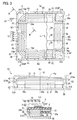
Fig. 1] Fig. 1 is a diagram illustrating the structure of a coil unit for contactless power supply according to a first embodiment of the present invention, (a) is a plan view, (b) is a side view, and (c) is a sectional view taken along line A-A in (a). - [
Fig. 2] Fig. 2 is a diagram illustrating a magnetic flux density distribution of a coil in a vicinity area in a coil axial direction during a contactless power supply operation. - [
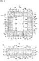
Fig. 3] Fig. 3 is a diagram illustrating the structure of a coil unit for contactless power supply according to a second embodiment of the present invention, (a) is a plan view, (b) is a side view, and (c) is a sectional view taken along line B-B in (a). - [
Fig. 4] Fig. 4 is a diagram illustrating the structure of a coil unit for contactless power supply according to a third embodiment of the present invention, (a) is a plan view, and (b) is a side view. - [
Fig. 5] Fig. 5 is a diagram illustrating an example of a corner section and a non-corner section of a coil. - Hereinafter, embodiments of the present invention will be described with reference to the drawings.
- A coil unit U1 for contactless power supply according to a first embodiment of the present invention is a device that supplies power in a contactless manner to an electric vehicle stopped at a predetermined position. When high-frequency power is supplied from a power supply unit, the coil unit U1 supplies power to an in-vehicle battery or the like via a coil unit for power reception mounted in an electric vehicle.
- As illustrated in (a), (b) of
Fig. 1 , the coil unit U1 includes acoil section 10 having a coil axis X approximately parallel to a vertical direction, acore section 20 that supports thecoil section 10, and asupport section 30 that supports thecoil section 10 and thecore section 20 on the ground. The entire coil unit U1 is covered with aunit cover 40 installed in the ground. - The
coil section 10 includes aflat coil 11 having a thickness in the coil axial direction. Thecoil 11 is approximately plate-shaped as a whole, and has amajor surface 11a perpendicular to the coil axis X. - A
winding wire 13 of thecoil 11 is a litz wire wound in a rectangular spiral form in a coil axial direction view, and occupies an approximately rectangular annular area in a coil axial direction view. Thecoil 11 has 4 corner sections C corresponding to the corners of the rectangular annular area, and 4 non-corner sections NC corresponding to the sides of the rectangular annular area. - Each of the corner sections C includes a portion (hereinafter, a local maximum curvature section) 13ar that has a local maximum curvature in a coil axial direction view, out of the innermost
circumferential winding wire 13a, and a portion positioned between one side boundary surface P1 and the other side boundary surface P2 outwardly of the local maximum curvature section 13ar out of windingwires 13b to 13e other than the innermostcircumferential winding wire 13a. Here, the local maximum curvature section 13ar of the innermostcircumferential winding wire 13a is a portion of thewinding wire 13a, having a curvature greater than the average value (hereinafter the curvature average value) of the curvature of the circumference of thewinding wire 13a. The one side boundary surface P1 is a virtual plane surface that passes through one end of the local maximum curvature section 13ar and is perpendicular to the extension direction of thewinding wire 13a at the end, and the other side boundary surface P2 is a virtual plane surface that passes through the other end of the local maximum curvature section 13ar and is perpendicular to the extension direction of thewinding wire 13a at the other end. The corner sections C in this embodiment also include a local maximum curvature section 13er of the outermostcircumferential winding wire 13e. - In contrast, non-corner sections NC are the portions other than the corner sections C. Therefore, the curvature of the innermost
circumferential winding wire 13a everywhere forming each non-corner section NC is less than or equal to the above-mentioned curvature average value. In this embodiment, each non-corner section NC is an approximately linear portion that is interposed between adjacent corner sections C. - As illustrated in (a) to (c) of
Fig. 1 , thecore section 20 is provided downwardly (one side in the coil axial direction) of thecoil section 10, approximately parallel to themajor surface 11a of thecoil 11. Thecore section 20 has an approximately rectangular plate-like shape having a thickness in the coil axial direction, and the 4 sides are approximately parallel to respective extending directions of the non-corner sections NC of thecoil 11 in a coil axial direction view. - The
core section 20 includes a ferrite core 21 (a magnetic material core member), and acore case 23 that houses theferrite core 21. Theferrite core 21 forms a magnetic material layer parallel to themajor surface 11a of thecoil 11. Thecoil 11 is supported by the upper surface of thecore case 23. - The
core case 23 includes aresin tray 25 having an approximately rectangular outer shape in a coil axial direction view, and an approximately rectangular plate-shaped resin lid 27 that covers an upper opening of thetray 25. Thetray 25 includes an approximately rectangular plate-shaped bottom plate 25a, and acircumferential wall section 25b provided perpendicularly to the circumferential edge of thebottom plate 25a. The circumferential edge of thelid 27 is fastened to thecircumferential wall section 25b of thetray 25 by a non-magnetic material fastening tool or the like. The upper surface of thelid 27 is in contact with thewinding wire 13 of thecoil 11, and a housing space S for housing theferrite core 21 is formed between thetray 25 and thelid 27. Thebottom plate 25a of thetray 25 is provided withopenings 25c at four corners corresponding to the corner sections C of thecoil 11, and anupper end 31 a of a later-describedsupport member 31 is inserted in each of theopenings 25c. - The
ferrite core 21 includes multiple ferrite tiles 29 (magnetic material core members) with which the above-mentioned housing space S is covered. Eachferrite tile 29 has a rectangular parallelepiped shape with the approximately square bottom surface. It is to be noted that someferrite tiles 29 positioned inwardly of the innermostcircumferential winding wire 13a in a coil axial direction view may be thinned as needed according to a capacity required for the coil unit U1. - In this embodiment, the
multiple ferrite tiles 29 are disposed to be positioned immediately below one thewinding wires 13a to 13e (to be overlapped with thewinding wires 13a to 13e in projection in a coil axial direction) that form at least the non-corner sections NC of thecoil 11. Specifically, the upper surface of theferrite core 21 is at a position facing the non-corner sections NC of thecoil 11 in a coil axial direction with thelid 27 of thecore case 23 interposed therebetween. - As illustrated in (a) to (c) of
Fig. 1 , thesupport section 30 is provided below thecoil section 10, and supports thecoil section 10 and thecore section 20. Thesupport section 30 consists of aluminum support members 31 (thermal conductors) provided at four corners of thecore section 20, and abase plate 33 connected to the lower end of thesupport members 31 in a heat transferable manner. Thebase plate 33 is made of, for instance, metal such as aluminum, and is fastened to the ground by a fastening member such as an anchor bolt. - Each of the
support members 31 has a prism-like shape, and the upper end (heat input section of thermal conductor) 31a is inserted in an opening 25c of thetray 25 of thecore case 23. Thus, theferrite core 21 that forms a magnetic material layer and theupper ends 31a of thesupport member 31 are disposed in the same layer in close proximity to each other in the extending direction of the magnetic material layer. In other words, theferrite core 21 at the positions corresponding to the corner sections C of thecoil 11 is replaced by thesupport members 31. - The
upper ends 31a of thesupport members 31 are at positions facing the corner sections C of thecoil 11 in a coil axial direction with thelid 27 of thecore case 23 interposed therebetween. That is, theupper ends 31a are disposed to be positioned immediately below one thewinding wires 13a to 13e (to be overlapped with thewinding wires 13a to 13e in projection in a coil axial direction) that form at least the corner sections C of thecoil 11. Particularly in this embodiment, at least part of theupper ends 31a of thesupport member 31 is disposed to be overlapped with the outermostcircumferential winding wire 13e that forms the corner sections C in a coil axial direction view. - Also, the upper surface of the
upper ends 31a is approximately flush with the upper surface of theferrite tiles 29 disposed immediately below the windingwires 13a to 13e forming the non-corner sections NC, and is in contact with the lower surface (inner surface) of thelid 27 of thecore case 23. Also, a lateral surface of theupper ends 31a is in contact with a lateral surface of theferrite tiles 29 in thecore case 23. - Heat can be transferred between the
support members 31 and thecoil 11 via a contact surface between thelid 27 of thecore case 23 and the windingwire 13, via a contact surface between thelid 27 and the upper ends 31a of thesupport members 31, and via thelid 27. Also, heat can be transferred between thesupport members 31 and theferrite core 21 via a contact surface between the upper ends 31 a of thesupport members 31 and theferrite tiles 29. Therefore, heat generated in thecoil section 10 and thecore section 20 is dissipated to the outside (such as the ground) via thesupport members 31 and thebase plate 33. Eachsupport members 31 is made of aluminum and has a higher thermal conductivity than theferrite tiles 29, in short, theferrite core 21, and thus serves as an excellent thermal conductor. Also, the lower surface of thebase plate 33 is in contact with the ground at a large area, and thus serves as an excellent heat dissipation surface. - Hereinafter, the operational effects in this embodiment will be described.
- When high frequency power for contactless power supply is supplied to the coil unit U1 according to this embodiment, the magnetic flux density distribution in a peripheral area of the
coil 11 becomes non-uniform.Fig. 2 illustrates a magnetic flux density distribution and images (arrows) of typical lines of magnetic force in a vicinity area (the lower surface level of the coil 11) in a coil axial direction of thecoil 11. It is to be noted that inFig. 2 , the darker the color of an area, the higher the magnetic flux density. As indicated by arrows inFig. 2 , in the areas corresponding to the corner sections C of thecoil 11, the number of lines of magnetic force per unit volume of theferrite core 21 is smaller at a more outer position (at a position more separated from the coil axis X). Therefore, a low magnetic flux density area (for instance, an area LD) is likely to occur in corner section vicinity areas CP than in non-corner section vicinity areas NCP. Also, the windingwire 13 generates heat due to its resistance loss (copper loss) during a contactless power supply operation, thus the temperature of thecoil 11 increases. - In the coil unit U1 according to this embodiment, each
support member 31 is disposed to face a corner section C of thecoil 11, and thus thesupport member 31 which is a thermal conductor can be in close proximity to the windingwire 13 which is a heating element while suppressing the effect on the amount of magnetic flux passing through theferrite core 21. Also, since thesupport member 31 has a higher thermal conductivity than theferrite core 21, the heat of the windingwire 13 can be introduced to the outside efficiently. Thus, the heat dissipation performance of the coil unit U1 can be improved while suppressing degradation of the electromagnetic performance of thecoil 11. - As illustrated in
Fig. 2 , the magnetic flux density distribution in a peripheral area of thecoil 11 tends to be lower at a portion more outwardly of the areas corresponding to the corner sections C of thecoil 11. In this embodiment, at least part of thesupport members 31 is disposed to be overlapped with the outermost circumferential windingwire 13e in a coil axial direction view. Consequently, thesupport members 31 are disposed in an area having a lower magnetic flux density, and thus it is possible to suppress degradation of the electromagnetic performance of thecoil 11 more reliably. - Furthermore, in this embodiment, the
ferrite tiles 29 at the positions corresponding to the corner sections C of thecoil 11 are replaced by thealuminum support members 31 that have a higher thermal conductivity than theferrite core 21. For this reason, the heat dissipation performance is improved because the heat resistance decreases on the way from the windingwire 13 of thecoil 11 to a heat dissipation surface, as compared with the case where theferrite tiles 29 are left at the above-mentioned positions. - Also, since the
support members 31 are made of aluminum in this embodiment, the heat dissipation performance is improved because the heat resistance decreases on the way from the windingwire 13 of thecoil 11 to a heat dissipation surface, as compared with the case where thesupport members 31 are made of, for instance, resin. Particularly in this embodiment, thesupport members 31 are connected to thebase plate 33 fastened to the ground in a heat transferable manner, and thus the heat of the windingwire 13 can be efficiently dissipated via thebase plate 33. - Also, since the winding
wire 13 of thecoil 11 is wound in a rectangular spiral form in this embodiment, a larger coil area for each turn (area surrounded by the winding wire 13) can be provided in a rectangular area where vertical and horizontal dimensions are restricted in a plan view, and thus the inductance of thecoil 11 can be increased. - Furthermore, since the 4 non-corner sections NC are approximately linear in the
coil 11 of this embodiment, it is possible to provide a large difference between the curvature of the innermost circumferential windingwire 13a and the curvature average value of the windingwire 13a at each corner section C. Therefore, the tendency of relative decrease in magnetic flux density is more obvious in the corner section vicinity areas CP. Consequently, it is possible to suppress the effect made on the electromagnetic performance of thecoil 11 by thesupport members 31 disposed to face the corner sections C. - Next, a coil unit U2 for contactless power supply according to a second embodiment of the present invention will be described with reference to
Fig. 3 . It is to be noted that any component having the same function as the function of a component already described above is labeled with the same symbol, and a description is omitted. - The coil unit U2 differs from the coil unit U1 according to the first embodiment in that an upper end 31Aa of a
support member 31A (thermal conductor) is positioned outwardly of the innermost circumferential windingwire 13a in a coil axial direction view. - As illustrated in (a) to (c) of
Fig. 3 , like thesupport members 31 in the first embodiment, thesupport members 31A in this embodiment are provided at the four corners of thecore section 20. Thesupport members 31A each have a prism-like shape, and the upper ends 31Aa thereof are inserted in theopenings 25c provided at the four corners of thebottom plate 25a of thetray 25 of thecore case 23. The upper ends 31Aa face the corner sections C of thecoil 11 in a coil axial direction with thelid 27 of thecore case 23 interposed therebetween. - In this embodiment, the upper ends 31Aa of the
support members 31A are disposed to be positioned immediately below the outermost circumferential windingwire 13e (to be overlapped with the windingwire 13e in projection in a coil axial direction) that form at least the corner sections C of thecoil 11. In addition, the upper ends 31Aa are positioned outwardly of the innermost circumferential windingwire 13a of thecoil 11 in a coil axial direction view. Specifically, innermost ends 31AP of the upper ends 31Aa are positioned outwardly in a coil axial direction view of the innermost circumferential windingwire 13a that forms the corner sections C of thecoil 11. Thus, the upper ends 31Aa of thesupport members 31A are not positioned immediately below the innermost circumferential windingwire 13a (not overlapped with the windingwire 13a in projection in a coil axial direction), and thesupport members 31A are not present in portions CP1 (seeFig. 2 ) inwardly (closer to the coil axis X) of the corner section vicinity areas CP. In instead of thesupport members 31A,ferrite tiles 29a are disposed in the portions CP1. - With the coil unit U2 for contactless power supply according to this embodiment, the following effect can be obtained in addition to the same effect of the first embodiment.
- As illustrated in
Fig. 2 , in the portions CP1 inwardly of the corner section vicinity areas CP, an area with a locally high magnetic flux density is likely to be formed. Since thesupport members 31A are positioned outwardly of the innermost circumferential windingwire 13a in a coil axial direction view in this embodiment, theferrite core 21 can be disposed in high magnetic flux density areas which are formed in the portions CP1 inwardly of the corner section vicinity areas CP. Consequently, it is possible to further suppress degradation of the electromagnetic performance of thecoil 11. - Next, a coil unit U3 for contactless power supply according to a third embodiment of the present invention will be described with reference to
Fig. 4 . It is to be noted that any component having the same function as the function of a component already described above is labeled with the same symbol, and a description is omitted. - The coil unit U3 differs from the coil units U1, U2 according to the first and second embodiments mainly in the following two points. Specifically, the first point is that multiple
first support members 31B are disposed to face one non-corner section NC, andsecond ferrite tiles 29d (magnetic material core members) extending from the inside to the outside of thecoil 11 are disposed between thesefirst support members 31B. The second point is that multiplesecond support members 31C (thermal conductors) are disposed to face one corner section C, andthird ferrite tiles 29e (magnetic material members) extending from the inside to the outside of thecoil 11 are disposed between thesesecond support members 31C. - As illustrated in (a) and (b) of
Fig. 4 , theferrite core 21 in this embodiment includes multiplefirst ferrite tiles 29c with which the housing space S of thecore case 23 is covered, thesecond ferrite tiles 29d, and thethird ferrite tiles 29e. - The
first ferrite tiles 29c each have a rectangular parallelepiped shape with the approximately square bottom surface, and a rectangular area inwardly of the innermost circumferential windingwire 13a in a coil axial direction view is fully covered with thefirst ferrite tiles 29c. - The
second ferrite tiles 29d are disposed at predetermined intervals in the extending direction of each non-corner section NC of thecoil 11 so as to be positioned immediately below the winding wire 13 (be overlapped with the windingwire 13 in projection in a coil axial direction) that forms the non-corner sections NC of thecoil 11. Thesecond ferrite tiles 29d each have a rectangular parallelepiped shape with the approximately rectangular bottom surface, and are disposed so as to cross the windingwire 13 that forms the non-corner sections NC, in a coil axial direction view. Specifically, the inner side end, closer to the coil axis X, of eachsecond ferrite tile 29d is in contact with one of thefirst ferrite tiles 29c, and a magnetic path extending from the inside to the outside of a non-corner section NC in a coil axial direction view is formed. - The
third ferrite tiles 29e are disposed so as to be positioned immediately below the winding wire 13 (be overlapped with the windingwire 13 in projection in a coil axial direction) that forms the corner sections C of thecoil 11. Thethird ferrite tiles 29e each have a hexagonal prism shape with the elongated hexagonal bottom surface, and are disposed so as to cross the windingwire 13 that forms the corner sections C in a coil axial direction view, or to extend along the curvature radius direction of the windingwire 13 that forms the corner sections C. The inner side end, closer to the coil axis X, of eachthird ferrite tile 29e is in contact with the first orsecond ferrite tile third ferrite tile 29e, triangular spaces between thethird ferrite tile 29e and the two closestsecond ferrite tiles 29d in a coil axial direction view are formed. - The upper surface of each
third ferrite tile 29e is at a position facing a corner section C of thecoil 11 in a coil axial direction with thelid 27 of thecore case 23 interposed therebetween. In addition, the upper surface of eachsecond ferrite tile 29d is at a position facing a non-corner section NC of thecoil 11 in a coil axial direction with thelid 27 of thecore case 23 interposed therebetween. - In the
bottom plate 25a of thetray 25 of thecore case 23, openings 25c1, 25c2 are provided at positions corresponding to the above-mentioned spaces that are formed between thesecond ferrite tiles 29d and between thesecond ferrite tile 29d and thethird ferrite tile 29e. The later-described upper ends 31Ba of thefirst support members 31B are each inserted in the first opening 25c1 corresponding to a space between thesecond ferrite tiles 29d. Also, the later-described upper ends 31Ca of thesecond support member 31C are each inserted in the opening 25c2 corresponding to a space between thesecond ferrite tile 29d and thethird ferrite tile 29e. - As illustrated in (a) and (b) of
Fig. 4 , thesupport section 30 includes multiple aluminumfirst support members 31B andsecond support members 31C, and thebase plate 33 connected to the lower ends of the first andsecond support members - Each side of the
core section 20 is provided with 3 sets of thefirst support member 31B, and thecore section 20 is provided with totally 9 sets of thefirst support member 31B. Eachfirst support member 31B has a quadrangular prism shape, and the upper end 31Ba thereof is inserted in a first opening 25c1 of thetray 25. - The upper end 31Ba of each
first support member 31B faces a non-corner section NC of thecoil 11 in a coil axial direction with thelid 27 of thecore case 23 interposed therebetween, and is disposed so as to be positioned immediately below the winding wire 13 (be overlapped with the windingwire 13 in projection in a coil axial direction) that forms at least the non-corner sections NC. Also, the upper surface of the upper end 31Ba is approximately flush with the upper surface of thesecond ferrite tiles 29d, and is in contact with the lower surface (inner surface) of thelid 27 of thecore case 23. In addition, a lateral surface of the upper end 31Ba is in contact with lateral surfaces of the first andsecond ferrite tiles - Meanwhile, each of the four corners of the
core section 20 is provided with 2 sets of thesecond support member 31C. Eachsecond support member 31C has a triangular prism shape, and the upper end 31Ca is inserted in a second opening 25c2 of thetray 25. - The upper end 31Ca of each
second support member 31C faces a corner section C of thecoil 11 in a coil axial direction with thelid 27 of thecore case 23 interposed therebetween, and is disposed so as to be positioned immediately below the outermost circumferential windingwire 13e (be overlapped with the windingwire 13e in projection in a coil axial direction) that forms at least the corner sections C. Also, the upper surface of the upper end 31Ca is approximately flush with the upper surfaces of the second andthird ferrite tiles lid 27 of thecore case 23. In addition, a lateral surface of theupper end 31 Ca is in contact with lateral surfaces of the second andthird ferrite tiles - Also, heat can be transferred between the first and
second support members coil 11 via a contact surface between thelid 27 of thecore case 23 and the windingwire 13, a contact surface between thelid 27 and the upper ends 31Ba, 31Ca of the first andsecond support members lid 27. Also, heat can be transferred between thefirst support members 31B and theferrite core 21 via a contact surface between the upper ends 31Ba of thefirst support members 31B and the first andsecond ferrite tiles second support members 31C and theferrite core 21 via a contact surface between the upper ends 31 Ca of thesecond support members 31C and the second andthird ferrite tiles coil section 10 and thecore section 20 is dissipated to the outside (such as the ground) via the first andsecond support members base plate 33. - With the coil unit U3 for contactless power supply according to this embodiment, the following effect can be obtained in addition to the same effect of the first and second embodiments.
- In this embodiment, multiple
second support members 31C are disposed to face a corner section C of thecoil 11, and thethird ferrite tile 29e extending from the inside to the outside of thecoil 11 is disposed between thosesecond support members 31C. Therefore, in an area corresponding to each corner section C, a magnetic path along the flow of magnetic flux can be formed with less magnetic materials, and a large range of thesecond support member 31C which is a good thermal conductor can be provided. Thus, the heat dissipation performance of the coil unit U3 can be improved while suppressing degradation of the electromagnetic performance of thecoil 11. - Also, in this embodiment, multiple
first support members 31B are disposed to face a non-corner section NC of thecoil 11, and thesecond ferrite tile 29d extending from the inside to the outside of thecoil 11 is disposed between thosefirst support members 31B. Therefore, in an area corresponding to each non-corner section NC, a magnetic path along the flow of magnetic flux can be formed with less magnetic materials, and a large range of thefirst support member 31B which is a good thermal conductor can be provided. - The corner sections C of the
flat coil 11 may take various forms according to an inductance required for the coil and an acceptable curvature (a minimum bending radius) of the windingwire 13. For instance, as illustrated in (a) ofFig. 5 , the area surrounded by the windingwire 13 may be maximized for each turn by bending all windingwires 13 from the innermost to the outermost with a minimum bending radius in the predetermined corner areas. In this case, each corner section C includes a local maximum curvature section 13ar of the innermost circumferential windingwire 13a, and a portion that is positioned between one side boundary surface P1 and the other side boundary surface P2 and is outwardly of the local maximum curvature section 13ar in the other windingwires 13b to 13e. The corner section C includes a local maximum curvature section 13er of the outermost circumferential windingwire 13e. Also, each non-corner section NC is a portion that is interposed by the boundary surfaces P1, P2 between adjacent corner sections C, and is formed of an approximately linear windingwire 13 in thecoil 11 in (a) ofFig. 5 . - Also, when the winding
wire 13 is bendable, as illustrated in (b) ofFig. 5 , the corner section C includes a portion positioned between one side boundary surface P1 and the other side boundary surface P2 that pass through a bending point of the innermost circumferential windingwire 13a. Also, like thecoil 11 in (a) ofFig. 5 , the non-corner section NC includes a portion that is interposed by the boundary surfaces P1, P2 between adjacent corner sections C, and is formed of an approximately linear windingwire 13. - Also, as illustrated in (c) of
Fig. 5 , the windingwire 13 forming the non-corner section NC of thecoil 11 may be slightly bent in order to suppress the effects such as vibration or thermal expansion at the time of energization. Even in this case, each corner section C includes the local maximum curvature section 13ar of the innermost circumferential windingwire 13a, and a portion that is positioned between one side boundary surface P1 and the other side boundary surface P2 and is outwardly of the local maximum curvature section 13ar in the other windingwires 13b to 13e. The corner section C includes part of the local maximum curvature section 13er of the outermost circumferential windingwire 13e. It is to be noted that each portion colored in gray in (a) to (c) ofFig. 5 corresponds to the local maximum curvature section of each winding wire. - In addition, when the minimum bending radius of a winding wire is large or the number of turns of a winding wire is high, the innermost circumferential winding wire may be circular in a coil axial direction view. In this case, one of the winding wires other than the circular winding wire, and the one not circular and is positioned in the innermost in a coil axial direction view is regarded as the innermost circumferential winding wire, and the corner section C and the non-corner section NC may be defined.
- Although the embodiments of the present invention have been described above, those embodiments are merely illustrations for facilitating the understanding of the present invention, and the present invention is not limited to those embodiments. The technical scope of the present invention includes not only specific technical matters disclosed in the above-mentioned embodiments, but also various modifications, changes, alternative techniques that may be easily derived from the technical matters.
- For instance, although the coil units U1, U2, U3 in the above-mentioned embodiments are coil units for power supply, the present invention is also applicable to a coil unit for power reception mounted in an electric vehicle. For instance, the coil unit for power reception can be constituted by a coil section, a core section provided above the coil section, and a support section that supports the coil section and the core section by the lower surface of a vehicle body. The support section can be constituted by a support member inserted into a core case (thermal conductor), and an aluminum magnetic shield, connected to the support member and fastened to the lower surface of a vehicle body. In the coil unit, heat generated in the coil section and the core section is dissipated to the outside (such as air in the surroundings of the magnetic shield) via the support member and the magnetic shield.
- Also, in the above-mentioned embodiments, aluminum thermal conductors are adopted as the
support members ferrite core 21 can be adopted. From the viewpoint of suppressing heat generation at the time of energization, it is desirable that the member have low hysteresis loss and Eddy current loss. However, it is not necessary that the member is necessarily a non-magnetic material. It is to be noted that an aluminum material is most suitable from the aspect of cost. - Furthermore, although the
coil 11 of the above-mentioned embodiments has an approximately rectangular annular shape in a coil axial direction view, the shape of the coil is not particularly limited, and the present invention is applicable when the shape is non-circular. Examples of non-circular shape include a sector shape, a semi-circular shape, and a polygonal shape. In a polygonal coil, a corner section C is formed in each portion corresponding to a vertex, and a non-corner section NC is formed in each portion corresponding to a side. In a sector-shaped coil, a corner section C is formed in each portion corresponding to an intersection point between a radius and an arc, the central angle, and a non-corner section NC is formed in each portion corresponding to a radius, an arc. In a semi-circular coil, a corner section C is formed in each portion corresponding to both ends of a chord, and a non-corner section NC is formed in each portion corresponding to a chord, an arc. Therefore, the magnetic flux density distribution in a peripheral area of a non-circular coil becomes non-uniform, and like the case of the rectangular annular coil, an area having a lower magnetic flux density is likely to occur in a corner section vicinity area. Consequently, even in these coils, the thermal conductor is disposed to face a corner section C, and thus the thermal conductor can be disposed in close proximity to the winding wire which is a heating element, while suppressing the effect on the amount of magnetic flux passing through the core member. - Although the
coil section 10 has thesingle coil 11 in the above-mentioned embodiments, the coil section may include two or more coils disposed side by side in the perpendicular direction (horizontal direction) to the coil axis. Although the wire of thecoil 11 in the above-mentioned embodiments is wound 5 turns from the innermost to the outermost, the number of winding is not particularly limited, and may be less than 5 turns or more than 5 turns. - Furthermore, in the above-mentioned embodiments, the winding
wire 13 of thecoil 11 is wound from the innermost to the outermost without being overlapped in a coil axial direction. However, in part or all of the coil, the winding wire may be wound with two turns overlapped in a coil axial direction. - Also, in the above-mentioned embodiments, the electrical insulation performance is ensured by interposing the
lid 27 of thecore case 23 between theupper ends 31a, 31Aa, 31Ba, 31Ca of thesupport members coil 11. However, as long as sufficient insulation performance can be ensured by covering the windingwire 13 itself with an insulation layer, the upper surfaces of thesupport members wire 13. This causes the heat dissipation performance to be further improved. - Furthermore, in the above-mentioned embodiments, the
ferrite tiles 29 facing the corner sections C of thecoil 11 are replaced by thesupport members coil 11. However, thesupport members - According to the present invention, a coil unit for contactless power transmission can be provided.
-
- U1, U2, U3 coil unit for contactless power supply
- 11 coil (flat coil)
- C corner section
- NC non-corner section
- 13, 13a, 13b, 13c, 13d, 13e winding wire
- 21 ferrite core (magnetic material core member)
- 29 ferrite tile (magnetic material core member)
- 29d second ferrite tile (magnetic material core member)
- 29e third ferrite tile (magnetic material member)
- 31 support member (thermal conductor)
- 31A support member (thermal conductor)
- 31C second support member (thermal conductor)
Claims (4)
- A coil unit for contactless power transmission comprising:a non-circular flat coil that has a corner section and a non-corner section in a coil axial direction view;a core member made of a magnetic material disposed to face the non-corner section of the flat coil in a coil axial direction; anda thermal conductor that is disposed to face the corner section of the flat coil in the coil axial direction, and that has a higher thermal conductivity than the core member.
- The coil unit for contactless power transmission according to claim 1, wherein at least part of the thermal conductor is disposed to be overlapped with an outermost circumferential winding wire in the coil axial direction view.
- The coil unit for contactless power transmission according to claim 1 or 2, wherein the thermal conductor is positioned outwardly of an innermost circumferential winding wire in the coil axial direction view.
- The coil unit for contactless power transmission according to any one of claims 1 to 3, wherein a plurality of pieces of the thermal conductor are disposed to face the corner section, and a magnetic material member extending from an inner side to an outer side of the coil is disposed between the plurality of pieces of the thermal conductor.
Applications Claiming Priority (1)
| Application Number | Priority Date | Filing Date | Title |
|---|---|---|---|
| PCT/JP2015/060923 WO2016162965A1 (en) | 2015-04-08 | 2015-04-08 | Non-contact power transmission coil unit |
Publications (3)
| Publication Number | Publication Date |
|---|---|
| EP3282460A1 true EP3282460A1 (en) | 2018-02-14 |
| EP3282460A4 EP3282460A4 (en) | 2018-07-04 |
| EP3282460B1 EP3282460B1 (en) | 2020-01-08 |
Family
ID=57072267
Family Applications (1)
| Application Number | Title | Priority Date | Filing Date |
|---|---|---|---|
| EP15888458.5A Active EP3282460B1 (en) | 2015-04-08 | 2015-04-08 | Non-contact power transmission coil unit |
Country Status (9)
| Country | Link |
|---|---|
| US (1) | US10304617B2 (en) |
| EP (1) | EP3282460B1 (en) |
| JP (1) | JP6376285B2 (en) |
| KR (1) | KR101826495B1 (en) |
| CN (1) | CN107408453B (en) |
| CA (1) | CA2981770C (en) |
| MX (1) | MX364752B (en) |
| RU (1) | RU2657235C1 (en) |
| WO (1) | WO2016162965A1 (en) |
Cited By (2)
| Publication number | Priority date | Publication date | Assignee | Title |
|---|---|---|---|---|
| US11831168B2 (en) | 2021-10-07 | 2023-11-28 | Mahle International Gmbh | Ground assembly for an inductive charging device |
| US12580418B2 (en) | 2021-10-07 | 2026-03-17 | Mahle International Gmbh | Ground assembly for an inductive charging device |
Families Citing this family (20)
| Publication number | Priority date | Publication date | Assignee | Title |
|---|---|---|---|---|
| JP2018101725A (en) | 2016-12-21 | 2018-06-28 | トヨタ自動車株式会社 | Coil unit, power transmission device, and power reception device |
| KR101926765B1 (en) * | 2016-12-28 | 2018-12-11 | 한국철도기술연구원 | MODULE-TYPE CURRENT COLLECTOR(Pick-up) STRUCTURE FOR WIRELESS POWER TRANSFER |
| JP6729444B2 (en) * | 2017-02-23 | 2020-07-22 | トヨタ自動車株式会社 | Coil unit |
| JP6730211B2 (en) * | 2017-03-07 | 2020-07-29 | 株式会社Soken | Coil unit |
| JP2019021722A (en) * | 2017-07-14 | 2019-02-07 | トヨタ自動車株式会社 | Coil unit |
| ES2989521T3 (en) * | 2018-10-02 | 2024-11-26 | Nippon Steel Corp | Magnetic core |
| JP2020061517A (en) * | 2018-10-12 | 2020-04-16 | トヨタ自動車株式会社 | Coil unit |
| JP7246185B2 (en) * | 2018-12-28 | 2023-03-27 | 昭和電線ケーブルシステム株式会社 | Coil and coil manufacturing method |
| JP7283127B2 (en) * | 2019-02-27 | 2023-05-30 | Tdk株式会社 | coil parts |
| JP7182513B2 (en) * | 2019-05-24 | 2022-12-02 | 株式会社Soken | Magnetic components and power converters equipped with the same |
| DE102019216971A1 (en) | 2019-11-04 | 2021-05-06 | Mahle International Gmbh | Induction charging device for a vehicle charging system |
| DE102019216917A1 (en) * | 2019-11-04 | 2021-05-06 | Continental Reifen Deutschland Gmbh | Molded element, vulcanization mold and pneumatic vehicle tire |
| US10892088B1 (en) * | 2020-02-13 | 2021-01-12 | Texas Institute Of Science, Inc. | Stationary device for contactless electrical energy transmission |
| JP2021168340A (en) * | 2020-04-10 | 2021-10-21 | Tdk株式会社 | Coil unit, mobile body, power receiving device, and wireless power transmission system |
| JPWO2022024536A1 (en) * | 2020-07-31 | 2022-02-03 | ||
| US20220247217A1 (en) * | 2021-02-02 | 2022-08-04 | Nucurrent, Inc. | Wireless Power Transmitters And Associated Base Stations For Transmitting Power Over Varying Horizontal Position |
| DE102021205981A1 (en) * | 2021-06-11 | 2022-12-15 | Mahle International Gmbh | Bottom assembly for an inductive charging device |
| JP2023124707A (en) * | 2022-02-25 | 2023-09-06 | 大日本印刷株式会社 | Coil components, power transmission devices, power reception devices, and power transmission systems |
| DE102022203079A1 (en) * | 2022-03-29 | 2023-10-05 | Mahle International Gmbh | Stationary floor assembly for an inductive charging device |
| JP7645932B2 (en) * | 2023-06-26 | 2025-03-14 | 本田技研工業株式会社 | Coil Unit |
Family Cites Families (14)
| Publication number | Priority date | Publication date | Assignee | Title |
|---|---|---|---|---|
| JP4725078B2 (en) * | 2004-10-28 | 2011-07-13 | 大日本印刷株式会社 | Non-contact power feeding method and apparatus |
| JP4281837B2 (en) * | 2007-02-20 | 2009-06-17 | セイコーエプソン株式会社 | COIL UNIT, MANUFACTURING METHOD THEREOF, AND ELECTRONIC DEVICE |
| US7750783B2 (en) | 2007-02-20 | 2010-07-06 | Seiko Epson Corporation | Electronic instrument including a coil unit |
| JP4915579B2 (en) * | 2007-06-20 | 2012-04-11 | パナソニック株式会社 | Non-contact power transmission equipment |
| JP5118394B2 (en) * | 2007-06-20 | 2013-01-16 | パナソニック株式会社 | Non-contact power transmission equipment |
| JP2009005472A (en) * | 2007-06-20 | 2009-01-08 | Panasonic Electric Works Co Ltd | Non-contact power transmission equipment |
| JP2010074937A (en) * | 2008-09-18 | 2010-04-02 | Toyota Motor Corp | Non-contact power receiving apparatus and vehicle equipped with the same |
| JP2010245323A (en) | 2009-04-07 | 2010-10-28 | Seiko Epson Corp | Coil unit and electronic equipment |
| JP5602065B2 (en) | 2011-03-04 | 2014-10-08 | 長野日本無線株式会社 | Non-contact power transmission device |
| JP2012216687A (en) * | 2011-03-31 | 2012-11-08 | Sony Corp | Power reception coil, power reception device, and non contact power transmission system |
| JP2013005523A (en) * | 2011-06-14 | 2013-01-07 | Alps Electric Co Ltd | Wireless power transmission device |
| WO2013183665A1 (en) | 2012-06-05 | 2013-12-12 | 国立大学法人 埼玉大学 | Contactless feeding transformer |
| JP6112383B2 (en) * | 2012-06-28 | 2017-04-12 | パナソニックIpマネジメント株式会社 | Mobile device |
| JP2014183193A (en) * | 2013-03-19 | 2014-09-29 | Dexerials Corp | Antenna device and electronic equipment |
-
2015
- 2015-04-08 CN CN201580078365.9A patent/CN107408453B/en active Active
- 2015-04-08 RU RU2017135091A patent/RU2657235C1/en active
- 2015-04-08 EP EP15888458.5A patent/EP3282460B1/en active Active
- 2015-04-08 MX MX2017012466A patent/MX364752B/en active IP Right Grant
- 2015-04-08 CA CA2981770A patent/CA2981770C/en active Active
- 2015-04-08 KR KR1020177028679A patent/KR101826495B1/en not_active Expired - Fee Related
- 2015-04-08 US US15/564,800 patent/US10304617B2/en active Active
- 2015-04-08 JP JP2017511387A patent/JP6376285B2/en active Active
- 2015-04-08 WO PCT/JP2015/060923 patent/WO2016162965A1/en not_active Ceased
Cited By (2)
| Publication number | Priority date | Publication date | Assignee | Title |
|---|---|---|---|---|
| US11831168B2 (en) | 2021-10-07 | 2023-11-28 | Mahle International Gmbh | Ground assembly for an inductive charging device |
| US12580418B2 (en) | 2021-10-07 | 2026-03-17 | Mahle International Gmbh | Ground assembly for an inductive charging device |
Also Published As
| Publication number | Publication date |
|---|---|
| EP3282460A4 (en) | 2018-07-04 |
| WO2016162965A1 (en) | 2016-10-13 |
| EP3282460B1 (en) | 2020-01-08 |
| CN107408453A (en) | 2017-11-28 |
| CA2981770C (en) | 2018-04-03 |
| RU2657235C1 (en) | 2018-06-09 |
| JPWO2016162965A1 (en) | 2018-03-01 |
| JP6376285B2 (en) | 2018-08-22 |
| MX2017012466A (en) | 2018-01-30 |
| CA2981770A1 (en) | 2016-10-13 |
| MX364752B (en) | 2019-05-07 |
| US20180114629A1 (en) | 2018-04-26 |
| CN107408453B (en) | 2020-05-01 |
| US10304617B2 (en) | 2019-05-28 |
| KR101826495B1 (en) | 2018-02-06 |
| KR20170128774A (en) | 2017-11-23 |
Similar Documents
| Publication | Publication Date | Title |
|---|---|---|
| EP3282460B1 (en) | Non-contact power transmission coil unit | |
| JP6417713B2 (en) | Coil device | |
| CA2900786C (en) | Device having a winding arrangement and arrangement, in particular a charging station, for contactless transfer of energy to an electric vehicle, having a winding arrangement | |
| JP4654317B1 (en) | Reactor | |
| JP6357142B2 (en) | Core unit and wire harness | |
| JP6280592B2 (en) | Reactor | |
| JP2017184440A (en) | Feed coil unit, wireless power supply device and wireless power transmission device | |
| JP4618452B2 (en) | Reactor | |
| JP2017017874A (en) | Coil device | |
| JP6130347B2 (en) | Reactor | |
| JP6681164B2 (en) | Reactor | |
| JP5093329B2 (en) | Reactor | |
| JP6337610B2 (en) | Coil device | |
| JP2021097079A (en) | Solid iron core transformer | |
| JP2015220449A (en) | Reactor | |
| JP6619195B2 (en) | Reactor | |
| EP2942849B1 (en) | Circuit breaker box, and switching device for electric power | |
| KR100664509B1 (en) | External iron transformer and its manufacturing method | |
| JP6729444B2 (en) | Coil unit | |
| JP2020021873A (en) | Mold type static induction equipment |
Legal Events
| Date | Code | Title | Description |
|---|---|---|---|
| STAA | Information on the status of an ep patent application or granted ep patent |
Free format text: STATUS: THE INTERNATIONAL PUBLICATION HAS BEEN MADE |
|
| PUAI | Public reference made under article 153(3) epc to a published international application that has entered the european phase |
Free format text: ORIGINAL CODE: 0009012 |
|
| STAA | Information on the status of an ep patent application or granted ep patent |
Free format text: STATUS: REQUEST FOR EXAMINATION WAS MADE |
|
| 17P | Request for examination filed |
Effective date: 20171006 |
|
| AK | Designated contracting states |
Kind code of ref document: A1 Designated state(s): AL AT BE BG CH CY CZ DE DK EE ES FI FR GB GR HR HU IE IS IT LI LT LU LV MC MK MT NL NO PL PT RO RS SE SI SK SM TR |
|
| AX | Request for extension of the european patent |
Extension state: BA ME |
|
| A4 | Supplementary search report drawn up and despatched |
Effective date: 20180606 |
|
| RIC1 | Information provided on ipc code assigned before grant |
Ipc: B60L 11/18 20060101ALI20180529BHEP Ipc: H01F 38/14 20060101AFI20180529BHEP Ipc: B60L 5/00 20060101ALI20180529BHEP |
|
| DAV | Request for validation of the european patent (deleted) | ||
| DAX | Request for extension of the european patent (deleted) | ||
| STAA | Information on the status of an ep patent application or granted ep patent |
Free format text: STATUS: EXAMINATION IS IN PROGRESS |
|
| 17Q | First examination report despatched |
Effective date: 20190418 |
|
| REG | Reference to a national code |
Ref country code: DE Ref legal event code: R079 Ref document number: 602015045427 Country of ref document: DE Free format text: PREVIOUS MAIN CLASS: H01F0038140000 Ipc: B60L0053120000 |
|
| GRAP | Despatch of communication of intention to grant a patent |
Free format text: ORIGINAL CODE: EPIDOSNIGR1 |
|
| STAA | Information on the status of an ep patent application or granted ep patent |
Free format text: STATUS: GRANT OF PATENT IS INTENDED |
|
| RIC1 | Information provided on ipc code assigned before grant |
Ipc: B60L 53/12 20190101AFI20190909BHEP |
|
| INTG | Intention to grant announced |
Effective date: 20190926 |
|
| GRAS | Grant fee paid |
Free format text: ORIGINAL CODE: EPIDOSNIGR3 |
|
| GRAA | (expected) grant |
Free format text: ORIGINAL CODE: 0009210 |
|
| STAA | Information on the status of an ep patent application or granted ep patent |
Free format text: STATUS: THE PATENT HAS BEEN GRANTED |
|
| AK | Designated contracting states |
Kind code of ref document: B1 Designated state(s): AL AT BE BG CH CY CZ DE DK EE ES FI FR GB GR HR HU IE IS IT LI LT LU LV MC MK MT NL NO PL PT RO RS SE SI SK SM TR |
|
| REG | Reference to a national code |
Ref country code: GB Ref legal event code: FG4D |
|
| REG | Reference to a national code |
Ref country code: CH Ref legal event code: EP |
|
| REG | Reference to a national code |
Ref country code: DE Ref legal event code: R096 Ref document number: 602015045427 Country of ref document: DE |
|
| REG | Reference to a national code |
Ref country code: IE Ref legal event code: FG4D |
|
| REG | Reference to a national code |
Ref country code: AT Ref legal event code: REF Ref document number: 1222272 Country of ref document: AT Kind code of ref document: T Effective date: 20200215 |
|
| REG | Reference to a national code |
Ref country code: NL Ref legal event code: MP Effective date: 20200108 |
|
| REG | Reference to a national code |
Ref country code: LT Ref legal event code: MG4D |
|
| PG25 | Lapsed in a contracting state [announced via postgrant information from national office to epo] |
Ref country code: NO Free format text: LAPSE BECAUSE OF FAILURE TO SUBMIT A TRANSLATION OF THE DESCRIPTION OR TO PAY THE FEE WITHIN THE PRESCRIBED TIME-LIMIT Effective date: 20200408 Ref country code: RS Free format text: LAPSE BECAUSE OF FAILURE TO SUBMIT A TRANSLATION OF THE DESCRIPTION OR TO PAY THE FEE WITHIN THE PRESCRIBED TIME-LIMIT Effective date: 20200108 Ref country code: FI Free format text: LAPSE BECAUSE OF FAILURE TO SUBMIT A TRANSLATION OF THE DESCRIPTION OR TO PAY THE FEE WITHIN THE PRESCRIBED TIME-LIMIT Effective date: 20200108 Ref country code: LT Free format text: LAPSE BECAUSE OF FAILURE TO SUBMIT A TRANSLATION OF THE DESCRIPTION OR TO PAY THE FEE WITHIN THE PRESCRIBED TIME-LIMIT Effective date: 20200108 Ref country code: NL Free format text: LAPSE BECAUSE OF FAILURE TO SUBMIT A TRANSLATION OF THE DESCRIPTION OR TO PAY THE FEE WITHIN THE PRESCRIBED TIME-LIMIT Effective date: 20200108 Ref country code: PT Free format text: LAPSE BECAUSE OF FAILURE TO SUBMIT A TRANSLATION OF THE DESCRIPTION OR TO PAY THE FEE WITHIN THE PRESCRIBED TIME-LIMIT Effective date: 20200531 |
|
| PG25 | Lapsed in a contracting state [announced via postgrant information from national office to epo] |
Ref country code: BG Free format text: LAPSE BECAUSE OF FAILURE TO SUBMIT A TRANSLATION OF THE DESCRIPTION OR TO PAY THE FEE WITHIN THE PRESCRIBED TIME-LIMIT Effective date: 20200408 Ref country code: LV Free format text: LAPSE BECAUSE OF FAILURE TO SUBMIT A TRANSLATION OF THE DESCRIPTION OR TO PAY THE FEE WITHIN THE PRESCRIBED TIME-LIMIT Effective date: 20200108 Ref country code: SE Free format text: LAPSE BECAUSE OF FAILURE TO SUBMIT A TRANSLATION OF THE DESCRIPTION OR TO PAY THE FEE WITHIN THE PRESCRIBED TIME-LIMIT Effective date: 20200108 Ref country code: IS Free format text: LAPSE BECAUSE OF FAILURE TO SUBMIT A TRANSLATION OF THE DESCRIPTION OR TO PAY THE FEE WITHIN THE PRESCRIBED TIME-LIMIT Effective date: 20200508 Ref country code: HR Free format text: LAPSE BECAUSE OF FAILURE TO SUBMIT A TRANSLATION OF THE DESCRIPTION OR TO PAY THE FEE WITHIN THE PRESCRIBED TIME-LIMIT Effective date: 20200108 Ref country code: GR Free format text: LAPSE BECAUSE OF FAILURE TO SUBMIT A TRANSLATION OF THE DESCRIPTION OR TO PAY THE FEE WITHIN THE PRESCRIBED TIME-LIMIT Effective date: 20200409 |
|
| REG | Reference to a national code |
Ref country code: DE Ref legal event code: R097 Ref document number: 602015045427 Country of ref document: DE |
|
| PG25 | Lapsed in a contracting state [announced via postgrant information from national office to epo] |
Ref country code: CZ Free format text: LAPSE BECAUSE OF FAILURE TO SUBMIT A TRANSLATION OF THE DESCRIPTION OR TO PAY THE FEE WITHIN THE PRESCRIBED TIME-LIMIT Effective date: 20200108 Ref country code: RO Free format text: LAPSE BECAUSE OF FAILURE TO SUBMIT A TRANSLATION OF THE DESCRIPTION OR TO PAY THE FEE WITHIN THE PRESCRIBED TIME-LIMIT Effective date: 20200108 Ref country code: SK Free format text: LAPSE BECAUSE OF FAILURE TO SUBMIT A TRANSLATION OF THE DESCRIPTION OR TO PAY THE FEE WITHIN THE PRESCRIBED TIME-LIMIT Effective date: 20200108 Ref country code: DK Free format text: LAPSE BECAUSE OF FAILURE TO SUBMIT A TRANSLATION OF THE DESCRIPTION OR TO PAY THE FEE WITHIN THE PRESCRIBED TIME-LIMIT Effective date: 20200108 Ref country code: EE Free format text: LAPSE BECAUSE OF FAILURE TO SUBMIT A TRANSLATION OF THE DESCRIPTION OR TO PAY THE FEE WITHIN THE PRESCRIBED TIME-LIMIT Effective date: 20200108 Ref country code: SM Free format text: LAPSE BECAUSE OF FAILURE TO SUBMIT A TRANSLATION OF THE DESCRIPTION OR TO PAY THE FEE WITHIN THE PRESCRIBED TIME-LIMIT Effective date: 20200108 Ref country code: ES Free format text: LAPSE BECAUSE OF FAILURE TO SUBMIT A TRANSLATION OF THE DESCRIPTION OR TO PAY THE FEE WITHIN THE PRESCRIBED TIME-LIMIT Effective date: 20200108 |
|
| PLBE | No opposition filed within time limit |
Free format text: ORIGINAL CODE: 0009261 |
|
| STAA | Information on the status of an ep patent application or granted ep patent |
Free format text: STATUS: NO OPPOSITION FILED WITHIN TIME LIMIT |
|
| REG | Reference to a national code |
Ref country code: AT Ref legal event code: MK05 Ref document number: 1222272 Country of ref document: AT Kind code of ref document: T Effective date: 20200108 |
|
| PG25 | Lapsed in a contracting state [announced via postgrant information from national office to epo] |
Ref country code: MC Free format text: LAPSE BECAUSE OF FAILURE TO SUBMIT A TRANSLATION OF THE DESCRIPTION OR TO PAY THE FEE WITHIN THE PRESCRIBED TIME-LIMIT Effective date: 20200108 |
|
| REG | Reference to a national code |
Ref country code: CH Ref legal event code: PL |
|
| 26N | No opposition filed |
Effective date: 20201009 |
|
| PG25 | Lapsed in a contracting state [announced via postgrant information from national office to epo] |
Ref country code: LI Free format text: LAPSE BECAUSE OF NON-PAYMENT OF DUE FEES Effective date: 20200430 Ref country code: CH Free format text: LAPSE BECAUSE OF NON-PAYMENT OF DUE FEES Effective date: 20200430 Ref country code: IT Free format text: LAPSE BECAUSE OF FAILURE TO SUBMIT A TRANSLATION OF THE DESCRIPTION OR TO PAY THE FEE WITHIN THE PRESCRIBED TIME-LIMIT Effective date: 20200108 Ref country code: AT Free format text: LAPSE BECAUSE OF FAILURE TO SUBMIT A TRANSLATION OF THE DESCRIPTION OR TO PAY THE FEE WITHIN THE PRESCRIBED TIME-LIMIT Effective date: 20200108 Ref country code: LU Free format text: LAPSE BECAUSE OF NON-PAYMENT OF DUE FEES Effective date: 20200408 |
|
| REG | Reference to a national code |
Ref country code: BE Ref legal event code: MM Effective date: 20200430 |
|
| PG25 | Lapsed in a contracting state [announced via postgrant information from national office to epo] |
Ref country code: BE Free format text: LAPSE BECAUSE OF NON-PAYMENT OF DUE FEES Effective date: 20200430 Ref country code: PL Free format text: LAPSE BECAUSE OF FAILURE TO SUBMIT A TRANSLATION OF THE DESCRIPTION OR TO PAY THE FEE WITHIN THE PRESCRIBED TIME-LIMIT Effective date: 20200108 Ref country code: SI Free format text: LAPSE BECAUSE OF FAILURE TO SUBMIT A TRANSLATION OF THE DESCRIPTION OR TO PAY THE FEE WITHIN THE PRESCRIBED TIME-LIMIT Effective date: 20200108 |
|
| PG25 | Lapsed in a contracting state [announced via postgrant information from national office to epo] |
Ref country code: IE Free format text: LAPSE BECAUSE OF NON-PAYMENT OF DUE FEES Effective date: 20200408 |
|
| PG25 | Lapsed in a contracting state [announced via postgrant information from national office to epo] |
Ref country code: TR Free format text: LAPSE BECAUSE OF FAILURE TO SUBMIT A TRANSLATION OF THE DESCRIPTION OR TO PAY THE FEE WITHIN THE PRESCRIBED TIME-LIMIT Effective date: 20200108 Ref country code: MT Free format text: LAPSE BECAUSE OF FAILURE TO SUBMIT A TRANSLATION OF THE DESCRIPTION OR TO PAY THE FEE WITHIN THE PRESCRIBED TIME-LIMIT Effective date: 20200108 Ref country code: CY Free format text: LAPSE BECAUSE OF FAILURE TO SUBMIT A TRANSLATION OF THE DESCRIPTION OR TO PAY THE FEE WITHIN THE PRESCRIBED TIME-LIMIT Effective date: 20200108 |
|
| PG25 | Lapsed in a contracting state [announced via postgrant information from national office to epo] |
Ref country code: MK Free format text: LAPSE BECAUSE OF FAILURE TO SUBMIT A TRANSLATION OF THE DESCRIPTION OR TO PAY THE FEE WITHIN THE PRESCRIBED TIME-LIMIT Effective date: 20200108 Ref country code: AL Free format text: LAPSE BECAUSE OF FAILURE TO SUBMIT A TRANSLATION OF THE DESCRIPTION OR TO PAY THE FEE WITHIN THE PRESCRIBED TIME-LIMIT Effective date: 20200108 |
|
| PGFP | Annual fee paid to national office [announced via postgrant information from national office to epo] |
Ref country code: DE Payment date: 20250319 Year of fee payment: 11 |
|
| PGFP | Annual fee paid to national office [announced via postgrant information from national office to epo] |
Ref country code: GB Payment date: 20260319 Year of fee payment: 12 |
|
| PGFP | Annual fee paid to national office [announced via postgrant information from national office to epo] |
Ref country code: FR Payment date: 20260320 Year of fee payment: 12 |