EP3282454A1 - Power cable having flexible sectoral conductors - Google Patents
Power cable having flexible sectoral conductors Download PDFInfo
- Publication number
- EP3282454A1 EP3282454A1 EP17306058.3A EP17306058A EP3282454A1 EP 3282454 A1 EP3282454 A1 EP 3282454A1 EP 17306058 A EP17306058 A EP 17306058A EP 3282454 A1 EP3282454 A1 EP 3282454A1
- Authority
- EP
- European Patent Office
- Prior art keywords
- layer
- power cable
- conductors
- sector
- shaped
- Prior art date
- Legal status (The legal status is an assumption and is not a legal conclusion. Google has not performed a legal analysis and makes no representation as to the accuracy of the status listed.)
- Withdrawn
Links
- 239000004020 conductor Substances 0.000 title claims abstract description 151
- 239000000463 material Substances 0.000 claims abstract description 19
- 229910052751 metal Inorganic materials 0.000 claims description 35
- 239000002184 metal Substances 0.000 claims description 35
- 238000005253 cladding Methods 0.000 claims description 18
- 239000010410 layer Substances 0.000 description 116
- 238000000034 method Methods 0.000 description 29
- 230000008569 process Effects 0.000 description 28
- 238000009413 insulation Methods 0.000 description 9
- 230000001105 regulatory effect Effects 0.000 description 9
- 239000012212 insulator Substances 0.000 description 8
- 238000012545 processing Methods 0.000 description 8
- 239000011248 coating agent Substances 0.000 description 7
- 238000000576 coating method Methods 0.000 description 7
- 229920003020 cross-linked polyethylene Polymers 0.000 description 7
- 239000004703 cross-linked polyethylene Substances 0.000 description 7
- 229920002379 silicone rubber Polymers 0.000 description 7
- 230000006835 compression Effects 0.000 description 6
- 238000007906 compression Methods 0.000 description 6
- 230000008859 change Effects 0.000 description 5
- 239000004800 polyvinyl chloride Substances 0.000 description 5
- 229920006235 chlorinated polyethylene elastomer Polymers 0.000 description 4
- 230000000694 effects Effects 0.000 description 4
- 229920001971 elastomer Polymers 0.000 description 4
- 238000001125 extrusion Methods 0.000 description 4
- 238000004519 manufacturing process Methods 0.000 description 4
- 229920001084 poly(chloroprene) Polymers 0.000 description 4
- 239000005060 rubber Substances 0.000 description 4
- RYGMFSIKBFXOCR-UHFFFAOYSA-N Copper Chemical compound [Cu] RYGMFSIKBFXOCR-UHFFFAOYSA-N 0.000 description 3
- 229920000181 Ethylene propylene rubber Polymers 0.000 description 3
- 229910052802 copper Inorganic materials 0.000 description 3
- 239000010949 copper Substances 0.000 description 3
- 229920005989 resin Polymers 0.000 description 3
- 239000011347 resin Substances 0.000 description 3
- 239000000779 smoke Substances 0.000 description 3
- 229910000838 Al alloy Inorganic materials 0.000 description 2
- 239000004709 Chlorinated polyethylene Substances 0.000 description 2
- 239000004698 Polyethylene Substances 0.000 description 2
- 229910000831 Steel Inorganic materials 0.000 description 2
- 229910052782 aluminium Inorganic materials 0.000 description 2
- XAGFODPZIPBFFR-UHFFFAOYSA-N aluminium Chemical compound [Al] XAGFODPZIPBFFR-UHFFFAOYSA-N 0.000 description 2
- 150000001875 compounds Chemical class 0.000 description 2
- 239000002355 dual-layer Substances 0.000 description 2
- 238000005516 engineering process Methods 0.000 description 2
- 238000005246 galvanizing Methods 0.000 description 2
- 238000012986 modification Methods 0.000 description 2
- 230000004048 modification Effects 0.000 description 2
- -1 polyethylene Polymers 0.000 description 2
- 229920000573 polyethylene Polymers 0.000 description 2
- 229920000098 polyolefin Polymers 0.000 description 2
- 229920000915 polyvinyl chloride Polymers 0.000 description 2
- 230000009467 reduction Effects 0.000 description 2
- 239000002356 single layer Substances 0.000 description 2
- 239000010959 steel Substances 0.000 description 2
- 238000012360 testing method Methods 0.000 description 2
- 229920005992 thermoplastic resin Polymers 0.000 description 2
- 229920001187 thermosetting polymer Polymers 0.000 description 2
- 239000013585 weight reducing agent Substances 0.000 description 2
- 239000004677 Nylon Substances 0.000 description 1
- 239000004952 Polyamide Substances 0.000 description 1
- XUIMIQQOPSSXEZ-UHFFFAOYSA-N Silicon Chemical compound [Si] XUIMIQQOPSSXEZ-UHFFFAOYSA-N 0.000 description 1
- ATJFFYVFTNAWJD-UHFFFAOYSA-N Tin Chemical compound [Sn] ATJFFYVFTNAWJD-UHFFFAOYSA-N 0.000 description 1
- 230000015572 biosynthetic process Effects 0.000 description 1
- 239000011247 coating layer Substances 0.000 description 1
- 238000010276 construction Methods 0.000 description 1
- 238000002955 isolation Methods 0.000 description 1
- 229920001778 nylon Polymers 0.000 description 1
- 229920003023 plastic Polymers 0.000 description 1
- 239000004033 plastic Substances 0.000 description 1
- 229920002647 polyamide Polymers 0.000 description 1
- 229910052710 silicon Inorganic materials 0.000 description 1
- 239000010703 silicon Substances 0.000 description 1
- 239000007787 solid Substances 0.000 description 1
- 229910052718 tin Inorganic materials 0.000 description 1
- 239000011135 tin Substances 0.000 description 1
- 238000012546 transfer Methods 0.000 description 1
- 238000004804 winding Methods 0.000 description 1
Images

Classifications
-
- H—ELECTRICITY
- H01—ELECTRIC ELEMENTS
- H01B—CABLES; CONDUCTORS; INSULATORS; SELECTION OF MATERIALS FOR THEIR CONDUCTIVE, INSULATING OR DIELECTRIC PROPERTIES
- H01B9/00—Power cables
- H01B9/006—Constructional features relating to the conductors
-
- H—ELECTRICITY
- H01—ELECTRIC ELEMENTS
- H01B—CABLES; CONDUCTORS; INSULATORS; SELECTION OF MATERIALS FOR THEIR CONDUCTIVE, INSULATING OR DIELECTRIC PROPERTIES
- H01B7/00—Insulated conductors or cables characterised by their form
- H01B7/0009—Details relating to the conductive cores
-
- H—ELECTRICITY
- H01—ELECTRIC ELEMENTS
- H01B—CABLES; CONDUCTORS; INSULATORS; SELECTION OF MATERIALS FOR THEIR CONDUCTIVE, INSULATING OR DIELECTRIC PROPERTIES
- H01B7/00—Insulated conductors or cables characterised by their form
- H01B7/0045—Cable-harnesses
-
- H—ELECTRICITY
- H01—ELECTRIC ELEMENTS
- H01B—CABLES; CONDUCTORS; INSULATORS; SELECTION OF MATERIALS FOR THEIR CONDUCTIVE, INSULATING OR DIELECTRIC PROPERTIES
- H01B7/00—Insulated conductors or cables characterised by their form
- H01B7/02—Disposition of insulation
-
- H—ELECTRICITY
- H01—ELECTRIC ELEMENTS
- H01B—CABLES; CONDUCTORS; INSULATORS; SELECTION OF MATERIALS FOR THEIR CONDUCTIVE, INSULATING OR DIELECTRIC PROPERTIES
- H01B7/00—Insulated conductors or cables characterised by their form
- H01B7/17—Protection against damage caused by external factors, e.g. sheaths or armouring
- H01B7/18—Protection against damage caused by wear, mechanical force or pressure; Sheaths; Armouring
- H01B7/20—Metal tubes, e.g. lead sheaths
-
- H—ELECTRICITY
- H01—ELECTRIC ELEMENTS
- H01B—CABLES; CONDUCTORS; INSULATORS; SELECTION OF MATERIALS FOR THEIR CONDUCTIVE, INSULATING OR DIELECTRIC PROPERTIES
- H01B9/00—Power cables
- H01B9/02—Power cables with screens or conductive layers, e.g. for avoiding large potential gradients
-
- H—ELECTRICITY
- H01—ELECTRIC ELEMENTS
- H01B—CABLES; CONDUCTORS; INSULATORS; SELECTION OF MATERIALS FOR THEIR CONDUCTIVE, INSULATING OR DIELECTRIC PROPERTIES
- H01B7/00—Insulated conductors or cables characterised by their form
- H01B7/04—Flexible cables, conductors, or cords, e.g. trailing cables
Definitions
- the present invention relates to a power cable having flexible shaped sectors and, more particularly, to a power cable having flexible shaped sectors, wherein it can firmly maintain the shape of sectors, can secure flexibility, and can be fabricated without replacing equipment even in existing equipment in which the processing process and insulation process of a shaped sector have been separated, thereby being capable of improving workability.
- a power cable in general, includes a conductor playing the role of the passage of an electrical flow within the cable and an insulating layer surrounding the conductor.
- the conductor of such a cable is regulated as a metric size in IEC 60228 and BS 6360, and as an American Wire Gage (AWG) in ASTM as shown in Table 1 below.
- AWG American Wire Gage
- Table 1 Classification of conductor IEC60228 BS6360 ASTM Solid conductor class 1 class 1 class A Stranded conductor class 2 class 2 class B,C,D Flexible conductor class 5 class 5 class I,K More flexible conductor class 6 class 6 class M Classification unit Metric Metric Circular Mil
- the shape of the conductor may be divided into a round conductor and a sector (fan-shaped) conduct.
- the round conductor may be divided into a common concentric conductor formed by twisting conductors in a spiral form in a conductor stranding process, and a compressed conductor and compacted conductor having a diameter reduced by minimizing the gap of wire rods using a mechanical compression method in a conductor stranding process.
- the sector conductor is fabricated in a fan shape by compacting concentric conductors in two-core or more multi-wire cables.
- the gap between wire rods can be reduced in a process of binding the concentric conductors.
- a cable using sector conductors does not require an additional filling for filling the gap and can reduce its diameter compared to a cable using round conductors (hereinafter abbreviated as a "round cable”), such as that illustrated in FIG. 1(a) . Accordingly, there are advantages in that the cable using sector conductors can be fabricated with light weight and can reduce costs because weight of a coating matter or metal sheath consumed for an actual sector cable may be smaller than that of the round cable although the coating matter or the metal sheath is coated in the same thickness compared to the round cable in a subsequent insulating process.
- each sector cable corresponding to two round cables (3C ⁇ 70mm 2 ,3C ⁇ 120mm 2 ) having different sizes are illustrated in Table 2 below.
- the sector cable is chiefly applied to an onshore cable because the prime cost can be reduced compared to the round cable in terms of cost when the cable is installed due to such diameter reduction and weight reduction effects of the sector cable.
- such a sector cable has a disadvantage in that use of the sector cable in a narrow space, such as a vessel, is very limited due to the lack of flexibility.
- Table 3 illustrates the result values of relative comparison tests for each item, which were performed on the assumption of the routing of a cable that passes through several curved points using a round cable and sector cable having the same size.
- the sector conductor can be extruded in a form having a specific thickness only when the head of an extruder from which an insulating matter is output rotates in the same cycle as that of the conductor when a sector cable is fabricated because a fan-shaped conductor is rotated at specific intervals. It is however practically impossible to extrude a compound of a rubber characteristic material in a constant thickness on the fan-shaped conductor that rotates at specific intervals. Accordingly, such a sector cable has many limitations in selecting an insulator, and the insulator of a sector cable now on the market uses, for example, cross-linked polyethylene (XLPE) as a compound having a plastic characteristic.
- XLPE cross-linked polyethylene
- cross-linked polyethylene XLPE
- XLPE cross-linked polyethylene
- Patent Document 1 Korean Patent Application Publication No. 10-2015-0108962 (October 01, 2015 ) discloses a technology regarding a sector cable.
- the sector cable cannot maintain a fan-shaped form in a subsequent insulating work process because the shape of sector conductors placed under a conveyance drum is disordered in a process of winding and stacking fan-shaped (sector) conductors on the conveyance drum although the shape of the fan-shaped conductors has to be maintained without being disordered up to an insulation process, that is, a next process.
- the sector conductor Due to such a problem, the sector conductor has to be reflected in the layout of a factory so that the processing work and insulating work of the sector conductor can be performed in one process at the same time. Accordingly, there were problems in that existing conductor processing equipment must be changed and insulating equipment must be invested for the purpose of sector conductor processing.
- Patent Document 1 KR 10-2015-0108962A, published on October 01, 2015 .
- an object of the present invention is to provide a power cable having flexible shaped sectors, which can implement a shaped sector having improved flexibility compared to a conventional sector conductor, can firmly maintain the fan-shaped form of shaped sectors and secure flexibility in a process of stacking the shaped sectors below a conveyance drum while being wound on the conveyance drum in order to convey the shaped sectors to an insulating process for the purpose of the insulation of the shaped sectors when fabricating the power cable using the shaped sectors, and can be fabricated without replacing equipment even in existing equipment in which the layouts of the processing process and insulation process of shaped sectors have been separated, thereby being capable of improving workability.
- One embodiment of the present invention for achieving the object is a power cable characterized in that in a power cable including one or a plurality of shaped sectors, the shaped sector includes inner conductors formed of first type wire cores and outer conductors formed of second type wire cores, and the first type wire cores and the second type wire cores are heterogeneous conductors having different materials and/or different wire shape.
- said shaped sector can comprise inner conductors and outer conductors, said inner conductors comprising wire cores of a first type, and said outer conductors comprising the outmost layer which includes wire cores of a second type, said first type of cores being different from said second type of cores in terms of materials or shapes, or in terms of materials and shapes.
- the diameter of the first type wire cores can be inferior to the diameter of the second type wire cores.
- the outer conductors can be pressed to form said sector shape.
- Said inner conductors can comprise multi-wire cores.
- Said outer conductors can comprise stranded conductors.
- Said inner conductors can comprise conductors of class 5 or 6 of IEC 60228 and BS 6360 standard, or class I, K or M of ASTM standard.
- Said outer conductors can comprise conductors of class 2 of IEC 60228 and BS 6360 standard, or class B of ASTM standard.
- the power cable having flexible shaped sectors according to one embodiment of the present invention may be configured as another embodiment further including an insulating layer surrounding the outskirt of said shaped sector.
- Said insulating layer can coat the outside of each of the shaped sectors by surrounding the shaped sector at a specific thickness.
- Said shaped sector further can comprise a separating layer being positioned between said insulating layer and said outer conductors, and surrounding the outskirt of said outer conductors.
- the power cable having flexible shaped sectors may be configured as yet another embodiment further including a binding layer combining each shaped sector.
- Said binding layer can bind the shaped sectors surrounded by the insulating layer, so that the bound shape forms a circular cross section and by compressing and binding neighboring shaped sectors so that the radius portions of the neighboring shaped sectors are subjected to a surface contact up to the central part of the circle.
- the power cable can further comprise an internal sheath layer surrounding said binding layer, an external metal cladding layer surrounding said internal sheath layer; and an external sheath layer surrounding said external metal cladding layer.
- a metal insulating layer can further be positioned between said binding layer and said internal sheath layer.
- the power cable having flexible shaped sectors may be configured as yet another embodiment further including a metal insulating layer surrounding the outside of the binding layer.
- the power cable having flexible shaped sectors according to each embodiment of the present invention may be configured to further include an internal sheath layer surrounding the outside of the conductor layer, the insulating layer, the binding layer or the metal insulating layer, an external metal cladding layer surrounding the outside of the internal sheath layer, and an external sheath layer surrounding the outside of the external metal cladding layer.
- each of the shaped sectors may be configured to include inner conductors formed by assembling and stranding a plurality of first type wire cores and outer conductors formed of second type wire cores different from the first type wire cores, disposed to surround the outermost side of the inner conductors, and formed to finish the shape of the assembly stranded wires.
- each of the shaped sectors may be configured to further include a separating layer surrounding the outside of the outer conductor in order to prevent the second type wire cores that form the outer conductors from adhering to an insulator to be coated in a next process.
- a shaped sector having improved flexibility can be fabricated using the shaped sector including the inner conductor and outer conductor formed of heterogeneous conductors. Furthermore, work productivity can be improved because a shaped sector can be conveyed to an insulating process after a process of manufacturing the shaped sector when fabricating a power cable using a shaped sector and thus the power cable can be fabricated without replacing equipment or a layout in existing factory equipment in which the layouts of the processing process and insulation process of the shaped sector have been separated.
- FIG. 2 is a cross-sectional view of a power cable having flexible shaped sectors according to one embodiment of the present invention.
- FIG. 3 is a cross-sectional view of a power cable including flexible shaped sectors according to another embodiment of the present invention.
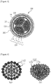
- FIGS. 4(a) and 4(b) are extracted cross-sectional views illustrating a round conductor prior to a change of a shape before compression and a shaped sector after a change of a shape by compression in the power cable having flexible shaped sectors according to the present invention.
- the power cable 100 may be configured to include the conductor layer of a cable in which a single or a plurality of shaped sectors 110 including inner conductors 111 and outer conductors 112 formed of heterogeneous conductors, and an insulating layer 114 is disposed in a radial form, a binding layer 120 binding the shaped sectors 110 of the conductor layer, an internal sheath layer 130 surrounding the outside of the binding layer 120, an external metal cladding layer 140 surrounding the outside of the internal sheath layer 130, and an external sheath layer 150 surrounding the outside of the external metal cladding layer 140.
- the power cable 100 may be configured to include the conductor layer of a cable in which a plurality of shaped sectors 110 including inner conductors 111 and outer conductors 112 formed of heterogeneous conductors, separating layers 113, and insulating layers 114, is disposed in a radial form, a binding layer 120 binding the shaped sectors 110 of the conductor layer, a metal insulating layer 121 surrounding the outside of the binding layer 120, an internal sheath layer 130 surrounding the outside of the metal insulating layer 121, an external metal cladding layer 140 surrounding the outside of the internal sheath layer 130, and an external sheath layer 150 surrounding the outside of the external metal cladding layer 140.
- the shaped sector 110 includes the inner conductors 111 and the outer conductors 112 bound by twisting the inner conductors 111 and the outer conductors 112 in a spiral form at constant interval and formed of heterogeneous conductors.
- the shaped sector 110 may be formed into a round conductor by the inner conductors 111 and the outer conductors 112. Thereafter, the round conductor may be processed in a fan-shaped form, such as that illustrated in FIG. 4(b) , by changing the shape of the round conductor by compression.
- each of the shaped sectors 110 may implement one embodiment through a configuration including the inner conductors 111, the outer conductors 112, and the insulating layer 114 surrounding the outskirts of the outer conductors.
- each of the shaped sectors 110 may implement another embodiment through a configuration including the inner conductors 111, the outer conductors 112, the separating layer 113 surrounding the outskirts of the outer conductors 112, and the insulating layer 114 coating the outside of the separating layer 113 by surrounding the separating layer 113 at a specific thickness.
- the inner conductors 111 are formed by assembling and stranding a plurality of first type wire cores.
- the first type wire cores include stranded wires according to the conductors of class 5 or 6 regulated in IEC 60228 and BS 6360, or the conductors of class I, K or M regulated in ASTM.
- the outer conductors 112 are formed of second type wire cores different from the first type wire cores.
- the outer conductors 112 are disposed to surround the outmost side of the inner conductors 111 and to finish the shape of the assembly stranded wires forming the inner conductors 111.
- the second type wire cores include the conductors of class 2 regulated in IEC 60228 and BS 6360, or stranded wires according to the regulations of class B regulated in ASTM.
- the shaped sector of the present invention includes the inner conductors 111 formed of the first type wire cores and the outer conductors 112 formed of the second type wire cores.
- the first class and the second class have different materials or wire shapes, or are heterogeneous conductors having different materials and wire shapes.
- the shaped sector is characterized in that the diameter of the first type wire core is very smaller than that of the second type wire core.
- the separating layer 113 is formed to prevent the second type wire cores that form the outer conductors 112 from adhering to an insulator to be coated in a next process.
- Such an isolation coating layer 113 is configured to generally surround the outside of the outer conductors 112.
- the insulating layer 114 may be configured by the coating of a single layer including a single material or an insulator of a dual layer form including two different materials.
- Such an insulating layer 114 may be made of any one or two materials selected from polyvinyl chloride (PVC), polyvinyl chloride/nylon (PVC/polyamide), ethylene propylene rubber (EPR), cross-linked polyethylene (XLPE), low-smoke halogen-free ethylene propylene rubber (LSEPR), low-smoke halogen-free cross-linked polyolefin (LSXLPO), low-smoke halogen-free silicon rubber (LS silicon), silicon rubber (SR), and cross-linked polyolefin (XLPO).
- PVC polyvinyl chloride
- PVC/polyamide ethylene propylene rubber
- EPR ethylene propylene rubber
- XLPE low-smoke halogen-free ethylene propylene rubber
- LSEPR low-
- the shaped sectors 110 surrounded by the insulating layer 114 are disposed and bound in a radial form so that the bound shape forms a circular cross section, and neighboring shaped sectors 110 are compressed and bound so that the radius portions of the neighboring shaped sectors 110 are subjected to a surface contact up to the central part of the circle.
- the metal insulating layer 121 generally surrounding the circumference of the binding layer 120 may be formed to surround the outside of the binding layer 120.
- Such a combined layer 120 binds the plurality of insulated shaped sectors by twisting the plurality of insulated shaped sectors in a spiral form at specific intervals so that a cross-sectional shape of the shaped sector is a circle, and may be formed of one or two or more tape layers by properly binding tapes after being bound.
- the metal insulating layer 121 may preferably include any one layer selected from one or two or more tape layers, a braid or concentric wire rod layer, and a binding layer of a wire rod and a tape.
- the internal sheath layer 130 is formed to surround the outside of the binding layer 120 or metal insulating layer 121.
- the external metal cladding layer 140 surrounding the outside of the internal sheath layer 130 and the external sheath layer 150 surrounding the outside of the external metal cladding layer 140 may be sequentially formed on the internal sheath layer 130.
- the internal sheath layer 130 may be formed by coating it on the binding layer 120 or the metal insulating layer 121 by extrusion at a specific thickness or may be formed by binding the internal sheath layer 130 and the binding layer 120 or the metal insulating layer 121 so that they overlap.
- the internal sheath layer 130 is preferably made of any one material selected from polyvinyl chloride (PVC), halogen-free thermosetting resins, halogen-free thermoplastic resins, chlorosulphonated polyethylene rubber (CSP), polychloroprene rubber (CR), chlorinated polyethylene rubber (CPE), and silicon rubber (SR).
- the external metal cladding layer 140 may include any one of a circular wire rod or a flat wire rod, a double-sided tape, and a metal-braided layer.
- the external metal cladding layer 140 includes a circular wire rod or a flat wire rod, it may be made of any one material selected from galvanized metal, copper, tin-coated copper, aluminum, and an aluminum alloy.
- the external metal cladding layer 140 includes a double-sided tape, it may be made of any one material selected from a steel sheet, a galvanizing steel sheet, aluminum, and an aluminum alloy.
- the external metal cladding layer 140 includes a metal-braided layer, it may be made of any one material selected from a galvanizing steel-wire braid and a copper braid.
- the external sheath layer 150 is formed by coating it on the external metal cladding layer 140 at a specific thickness by extrusion.
- the external sheath layer 150 may be made of any one material selected from polyvinyl chloride (PVC), halogen-free thermosetting resins, halogen-free thermoplastic resins, chlorosulphonated polyethylene rubber (CSP), chloroprene rubber (CR), chlorinated polyethylene rubber (CPE), and silicon rubber (SR).
- PVC polyvinyl chloride
- CSP chlorosulphonated polyethylene rubber
- CR chloroprene rubber
- CPE chlorinated polyethylene rubber
- SR silicon rubber
- the inner conductors 111 of the shaped sector 110 are the first type wire cores and are wires according to the regulations of the conductors of class 5 or 6 regulated in IEC 60228 and BS 6360, or the conductors of class I, K or M regulated in ASTM, and they have a multi-wire form. Accordingly, the inner conductor 111 has the flexible conductor or more flexible conductor form of Table 1, and has a characteristic in that it has better availability than a conventional sector conductor.
- the round conductor include the inner conductors 111 and the outer conductors 112 which are the second type wire cores different from the first type wire cores and wires according to the regulations of the conductors of class 2 regulated in IEC 60228 and BS 6360, or the regulations of the conductors of class B regulated in ASTM, have the stranded conductor form of Table 1, and are formed of heterogeneous conductors, that is, the first type wire cores formed of the second type wire cores, respectively, by disposing the round conductor to generally surround the outermost side of the inner conductors 111, is formed as illustrated in FIG. 4(a) .
- the shape of the round conductor is changed into a sector (fan shape) form as illustrated in FIG. 4(b) by compressing the round conductor formed as described above.
- the separating layer 113 surrounding the outside of the outer conductors 112 may be further formed on the outer circumference of the outer conductors 112 whose shape has been changed into the sector form in order to prevent the second type wire cores that form the outer conductors 112 from adhering to an insulator to be coated in a next process, if necessary.
- the insulating layer 114 is formed at a specific thickness by coating the insulator having a single layer made of a single material or a dual layer made of two different materials on the outside of the shaped sectors 110.
- the binding layer 120 is formed on the outside of the plurality of shaped sectors 110 twisted in a spiral form at specific intervals by binding and disposing the shaped sectors 110 surrounded by the insulating layer 114 in a radial form so that the bound shape forms a circular cross section and by compressing and binding neighboring shaped sectors 110 so that the radius portions of the neighboring shaped sectors 110 are subjected to a surface contact up to the central part of the circle. Accordingly, the conductor layer forming the cable bounded by the plurality of shaped sectors 110 can be formed.
- the metal insulating layer 121 may be formed on the outside of the binding layer 120, if necessary, using any one of one or two or more tape layers, a braid or concentric wire rod layer, and a binding layer of a wire rod and a tape so that the metal insulating layer 121 surrounds the outside of the binding layer 120.
- the inner conductors 111 and the outer conductors 112 within each of the shaped sectors 110 are divided into different types of conductors and primarily formed. Accordingly, in a conductor processing process, the fan-shaped form of the shaped sector can be firmly maintained without being disordered in a process of stacking the shaped sectors 110 below a conveyance drum while being wound on the conveyance drum in order to transfer the shaped sectors 110 to an insulation process, and flexibility can be also be secured.
- the internal sheath layer 130 coated by extrusion or bound in an overlapping manner at a specific thickness the external metal cladding layer 140 formed of any one of a circular wire rod or flat wire rod, a double-sided tape, and a metal-braided layer, and the external sheath layer 150 coated by extrusion at a specific thickness can be sequentially formed on the outside of the binding layer 120 or the metal insulating layer 121.
- the shape of the shaped sectors can be firmly maintained in a process of transferring and stacking the shaped sectors when a power cable is fabricated. Accordingly, the power cable can be fabricated without replacing equipment even in existing equipment in which the layouts of the processing process and insulation process of a conductor have been separated, and a limitation to use of the shaped sectors can be overcome through an increase in the flexibility of the shaped sectors.
Landscapes
- Insulated Conductors (AREA)
Abstract
Description
- The present invention relates to a power cable having flexible shaped sectors and, more particularly, to a power cable having flexible shaped sectors, wherein it can firmly maintain the shape of sectors, can secure flexibility, and can be fabricated without replacing equipment even in existing equipment in which the processing process and insulation process of a shaped sector have been separated, thereby being capable of improving workability.
- In general, a power cable includes a conductor playing the role of the passage of an electrical flow within the cable and an insulating layer surrounding the conductor. The conductor of such a cable is regulated as a metric size in IEC 60228 and BS 6360, and as an American Wire Gage (AWG) in ASTM as shown in Table 1 below.
[Table 1] Classification of conductor IEC60228 BS6360 ASTM Solid conductor class 1 class 1 class A Stranded conductor class 2 class 2 class B,C,D Flexible conductor class 5 class 5 class I,K More flexible conductor class 6 class 6 class M Classification unit Metric Metric Circular Mil - The shape of the conductor may be divided into a round conductor and a sector (fan-shaped) conduct.
- The round conductor may be divided into a common concentric conductor formed by twisting conductors in a spiral form in a conductor stranding process, and a compressed conductor and compacted conductor having a diameter reduced by minimizing the gap of wire rods using a mechanical compression method in a conductor stranding process.
- The sector conductor is fabricated in a fan shape by compacting concentric conductors in two-core or more multi-wire cables. The gap between wire rods can be reduced in a process of binding the concentric conductors.
- Accordingly, a cable using sector conductors (hereinafter abbreviated as a "sector cable" and refer to
FIG. 1(b) ) does not require an additional filling for filling the gap and can reduce its diameter compared to a cable using round conductors (hereinafter abbreviated as a "round cable"), such as that illustrated inFIG. 1(a) . Accordingly, there are advantages in that the cable using sector conductors can be fabricated with light weight and can reduce costs because weight of a coating matter or metal sheath consumed for an actual sector cable may be smaller than that of the round cable although the coating matter or the metal sheath is coated in the same thickness compared to the round cable in a subsequent insulating process. For example, the diameter reduction and weight reduction effects of each sector cable corresponding to two round cables (3C×70mm2,3C×120mm2) having different sizes are illustrated in Table 2 below.[Table 2] Size Total diameter (mm) Weight (kg) Class 2 Sector % Class 2 Sector % 3C×70mm2 32.2 26.6 -17.3 2.38 2.21 -7.1 3C×120mm2 40.6 33.0 -18.7 4.03 3.73 -7.4 - The sector cable is chiefly applied to an onshore cable because the prime cost can be reduced compared to the round cable in terms of cost when the cable is installed due to such diameter reduction and weight reduction effects of the sector cable.
- However, such a sector cable has a disadvantage in that use of the sector cable in a narrow space, such as a vessel, is very limited due to the lack of flexibility.
- Table 3 below illustrates the result values of relative comparison tests for each item, which were performed on the assumption of the routing of a cable that passes through several curved points using a round cable and sector cable having the same size.
[Table 3] Test item HIS SECTOR Ratio (%) Total diameter 36.8mm 29.8mm -19.0% Weight 2880kg/km 2462kg/km -14.5% Traction power 61.2kg 79.6kg 30% Friction resistance 2.12 3.24 52% - As illustrated in Table 3, it may be seen that in the case of the sector cable, a traction power required to move the cable is about 30% or more compared to the round cable due to the lack of flexibility.
- Meanwhile, the sector conductor can be extruded in a form having a specific thickness only when the head of an extruder from which an insulating matter is output rotates in the same cycle as that of the conductor when a sector cable is fabricated because a fan-shaped conductor is rotated at specific intervals. It is however practically impossible to extrude a compound of a rubber characteristic material in a constant thickness on the fan-shaped conductor that rotates at specific intervals. Accordingly, such a sector cable has many limitations in selecting an insulator, and the insulator of a sector cable now on the market uses, for example, cross-linked polyethylene (XLPE) as a compound having a plastic characteristic.
- However, such cross-linked polyethylene (XLPE), etc. has a disadvantage in that it is not eco-friendly because resins cannot be recycled if the lifespan of the cable expires and thus cross-linked polyethylene are inevitably discarded by incineration.
- Accordingly, Korean Patent Application Publication No.
10-2015-0108962 (October 01, 2015 - In accordance with Patent Document 1, light weight can be achieved while reducing the external diameter of the cable, sector insulation can be performed without sector chafing or falling-behind, and manufacturing costs can be reduced while maintaining resistance performance of a conductor, but the flexibility of the sector cable has not been improved as illustrated in Table 3.
- Furthermore, in a cable manufacturing process, the sector cable cannot maintain a fan-shaped form in a subsequent insulating work process because the shape of sector conductors placed under a conveyance drum is disordered in a process of winding and stacking fan-shaped (sector) conductors on the conveyance drum although the shape of the fan-shaped conductors has to be maintained without being disordered up to an insulation process, that is, a next process.
- Due to such a problem, the sector conductor has to be reflected in the layout of a factory so that the processing work and insulating work of the sector conductor can be performed in one process at the same time. Accordingly, there were problems in that existing conductor processing equipment must be changed and insulating equipment must be invested for the purpose of sector conductor processing.
- (Patent Document 1)
KR 10-2015-0108962A, published on October 01, 2015 - Accordingly, the present invention has been invented to solve the above problems, and an object of the present invention is to provide a power cable having flexible shaped sectors, which can implement a shaped sector having improved flexibility compared to a conventional sector conductor, can firmly maintain the fan-shaped form of shaped sectors and secure flexibility in a process of stacking the shaped sectors below a conveyance drum while being wound on the conveyance drum in order to convey the shaped sectors to an insulating process for the purpose of the insulation of the shaped sectors when fabricating the power cable using the shaped sectors, and can be fabricated without replacing equipment even in existing equipment in which the layouts of the processing process and insulation process of shaped sectors have been separated, thereby being capable of improving workability.
- One embodiment of the present invention for achieving the object is a power cable characterized in that in a power cable including one or a plurality of shaped sectors, the shaped sector includes inner conductors formed of first type wire cores and outer conductors formed of second type wire cores, and the first type wire cores and the second type wire cores are heterogeneous conductors having different materials and/or different wire shape.
- More particularly, said shaped sector can comprise inner conductors and outer conductors, said inner conductors comprising wire cores of a first type, and said outer conductors comprising the outmost layer which includes wire cores of a second type, said first type of cores being different from said second type of cores in terms of materials or shapes, or in terms of materials and shapes.
- The diameter of the first type wire cores can be inferior to the diameter of the second type wire cores.
- The outer conductors can be pressed to form said sector shape.
- Said inner conductors can comprise multi-wire cores.
- Said outer conductors can comprise stranded conductors.
- Said inner conductors can comprise conductors of class 5 or 6 of IEC 60228 and BS 6360 standard, or class I, K or M of ASTM standard.
- Said outer conductors can comprise conductors of class 2 of IEC 60228 and BS 6360 standard, or class B of ASTM standard.
- The power cable having flexible shaped sectors according to one embodiment of the present invention may be configured as another embodiment further including an insulating layer surrounding the outskirt of said shaped sector.
- Said insulating layer can coat the outside of each of the shaped sectors by surrounding the shaped sector at a specific thickness.
- Said shaped sector further can comprise a separating layer being positioned between said insulating layer and said outer conductors, and surrounding the outskirt of said outer conductors.
- The power cable having flexible shaped sectors may be configured as yet another embodiment further including a binding layer combining each shaped sector.
- Said binding layer can bind the shaped sectors surrounded by the insulating layer, so that the bound shape forms a circular cross section and by compressing and binding neighboring shaped sectors so that the radius portions of the neighboring shaped sectors are subjected to a surface contact up to the central part of the circle.
- In a preferred embodiment, the power cable can further comprise an internal sheath layer surrounding said binding layer, an external metal cladding layer surrounding said internal sheath layer; and an external sheath layer surrounding said external metal cladding layer. A metal insulating layer can further be positioned between said binding layer and said internal sheath layer.
- Furthermore, the power cable having flexible shaped sectors may be configured as yet another embodiment further including a metal insulating layer surrounding the outside of the binding layer.
- The power cable having flexible shaped sectors according to each embodiment of the present invention may be configured to further include an internal sheath layer surrounding the outside of the conductor layer, the insulating layer, the binding layer or the metal insulating layer, an external metal cladding layer surrounding the outside of the internal sheath layer, and an external sheath layer surrounding the outside of the external metal cladding layer.
- Furthermore, in the power cable having flexible shaped sectors according to each embodiment of the present invention, each of the shaped sectors may be configured to include inner conductors formed by assembling and stranding a plurality of first type wire cores and outer conductors formed of second type wire cores different from the first type wire cores, disposed to surround the outermost side of the inner conductors, and formed to finish the shape of the assembly stranded wires.
- Furthermore, each of the shaped sectors may be configured to further include a separating layer surrounding the outside of the outer conductor in order to prevent the second type wire cores that form the outer conductors from adhering to an insulator to be coated in a next process.
- In accordance with the present invention, a shaped sector having improved flexibility can be fabricated using the shaped sector including the inner conductor and outer conductor formed of heterogeneous conductors. Furthermore, work productivity can be improved because a shaped sector can be conveyed to an insulating process after a process of manufacturing the shaped sector when fabricating a power cable using a shaped sector and thus the power cable can be fabricated without replacing equipment or a layout in existing factory equipment in which the layouts of the processing process and insulation process of the shaped sector have been separated.
-
-
FIGS. 1(a) and 1(b) are cross-sectional views illustrating the insulation binding state of a round conductor and a sector conductor according to a conventional technology. -
FIG. 2 is a cross-sectional view of a power cable having flexible shaped sectors according to one embodiment of the present invention. -
FIG. 3 is a cross-sectional view of a power cable including flexible shaped sectors according to another embodiment of the present invention. -
FIGS. 4(a) and 4(b) are extracted cross-sectional views illustrating a round conductor prior to a change of a shape before compression and a shaped sector after a change of a shape by compression in the power cable having flexible shaped sectors according to the present invention. - An overall configuration and operation of a power cable having flexible shaped sectors according to the present invention are described in detail with reference to the accompanying drawings.
- Terms or words used in this specification and claims should not be construed as having common or dictionary meanings, but should be construed as having meanings and concepts that comply with the technical spirit of the present invention based on the principle that the inventor may appropriately define the terms or words as concepts for describing them in such a way as to best describe his or her invention. Accordingly, the constructions illustrated in the embodiments and drawings written in this specification are only the most preferred embodiments of the present invention. Therefore, it should be understood that a variety of equivalents and modifications capable of substituting the embodiments may be present at the time of filing of this application.
-
FIG. 2 is a cross-sectional view of a power cable having flexible shaped sectors according to one embodiment of the present invention.FIG. 3 is a cross-sectional view of a power cable including flexible shaped sectors according to another embodiment of the present invention.FIGS. 4(a) and 4(b) are extracted cross-sectional views illustrating a round conductor prior to a change of a shape before compression and a shaped sector after a change of a shape by compression in the power cable having flexible shaped sectors according to the present invention. - As illustrated in
FIG. 2 , thepower cable 100 according to one embodiment of the present invention may be configured to include the conductor layer of a cable in which a single or a plurality of shapedsectors 110 includinginner conductors 111 andouter conductors 112 formed of heterogeneous conductors, and an insulatinglayer 114 is disposed in a radial form, abinding layer 120 binding theshaped sectors 110 of the conductor layer, aninternal sheath layer 130 surrounding the outside of thebinding layer 120, an externalmetal cladding layer 140 surrounding the outside of theinternal sheath layer 130, and anexternal sheath layer 150 surrounding the outside of the externalmetal cladding layer 140. - As illustrated in
FIG. 3 , thepower cable 100 according to another embodiment of the present invention may be configured to include the conductor layer of a cable in which a plurality of shapedsectors 110 includinginner conductors 111 andouter conductors 112 formed of heterogeneous conductors, separatinglayers 113, and insulatinglayers 114, is disposed in a radial form, abinding layer 120 binding theshaped sectors 110 of the conductor layer, ametal insulating layer 121 surrounding the outside of thebinding layer 120, aninternal sheath layer 130 surrounding the outside of themetal insulating layer 121, an externalmetal cladding layer 140 surrounding the outside of theinternal sheath layer 130, and anexternal sheath layer 150 surrounding the outside of the externalmetal cladding layer 140. - In each embodiment, the shaped
sector 110 includes theinner conductors 111 and theouter conductors 112 bound by twisting theinner conductors 111 and theouter conductors 112 in a spiral form at constant interval and formed of heterogeneous conductors. As illustrated inFIG. 4(a) , the shapedsector 110 may be formed into a round conductor by theinner conductors 111 and theouter conductors 112. Thereafter, the round conductor may be processed in a fan-shaped form, such as that illustrated inFIG. 4(b) , by changing the shape of the round conductor by compression. - As illustrated in
FIG. 2 , each of the shapedsectors 110 may implement one embodiment through a configuration including theinner conductors 111, theouter conductors 112, and the insulatinglayer 114 surrounding the outskirts of the outer conductors. - Furthermore, as illustrated in
FIG. 3 , each of the shapedsectors 110 may implement another embodiment through a configuration including theinner conductors 111, theouter conductors 112, theseparating layer 113 surrounding the outskirts of theouter conductors 112, and the insulatinglayer 114 coating the outside of theseparating layer 113 by surrounding theseparating layer 113 at a specific thickness. - The
inner conductors 111 are formed by assembling and stranding a plurality of first type wire cores. In this case, the first type wire cores include stranded wires according to the conductors of class 5 or 6 regulated in IEC 60228 and BS 6360, or the conductors of class I, K or M regulated in ASTM. - The
outer conductors 112 are formed of second type wire cores different from the first type wire cores. Theouter conductors 112 are disposed to surround the outmost side of theinner conductors 111 and to finish the shape of the assembly stranded wires forming theinner conductors 111. In this case, the second type wire cores include the conductors of class 2 regulated in IEC 60228 and BS 6360, or stranded wires according to the regulations of class B regulated in ASTM. - Accordingly, the shaped sector of the present invention includes the
inner conductors 111 formed of the first type wire cores and theouter conductors 112 formed of the second type wire cores. The first class and the second class have different materials or wire shapes, or are heterogeneous conductors having different materials and wire shapes. The shaped sector is characterized in that the diameter of the first type wire core is very smaller than that of the second type wire core. - The
separating layer 113 is formed to prevent the second type wire cores that form theouter conductors 112 from adhering to an insulator to be coated in a next process. Such anisolation coating layer 113 is configured to generally surround the outside of theouter conductors 112. - The insulating
layer 114 may be configured by the coating of a single layer including a single material or an insulator of a dual layer form including two different materials. Such an insulatinglayer 114 may be made of any one or two materials selected from polyvinyl chloride (PVC), polyvinyl chloride/nylon (PVC/polyamide), ethylene propylene rubber (EPR), cross-linked polyethylene (XLPE), low-smoke halogen-free ethylene propylene rubber (LSEPR), low-smoke halogen-free cross-linked polyolefin (LSXLPO), low-smoke halogen-free silicon rubber (LS silicon), silicon rubber (SR), and cross-linked polyolefin (XLPO). - Furthermore, in the
binding layer 120 of thepower cable 100 according to each embodiment of the present invention, the shapedsectors 110 surrounded by the insulatinglayer 114 are disposed and bound in a radial form so that the bound shape forms a circular cross section, and neighboring shapedsectors 110 are compressed and bound so that the radius portions of the neighboring shapedsectors 110 are subjected to a surface contact up to the central part of the circle. Furthermore, themetal insulating layer 121 generally surrounding the circumference of thebinding layer 120 may be formed to surround the outside of thebinding layer 120. - Such a combined
layer 120 binds the plurality of insulated shaped sectors by twisting the plurality of insulated shaped sectors in a spiral form at specific intervals so that a cross-sectional shape of the shaped sector is a circle, and may be formed of one or two or more tape layers by properly binding tapes after being bound. - The
metal insulating layer 121 may preferably include any one layer selected from one or two or more tape layers, a braid or concentric wire rod layer, and a binding layer of a wire rod and a tape. - Furthermore, in the
power cable 100 according to each embodiment of the present invention, theinternal sheath layer 130 is formed to surround the outside of thebinding layer 120 ormetal insulating layer 121. The externalmetal cladding layer 140 surrounding the outside of theinternal sheath layer 130 and theexternal sheath layer 150 surrounding the outside of the externalmetal cladding layer 140 may be sequentially formed on theinternal sheath layer 130. - The
internal sheath layer 130 may be formed by coating it on thebinding layer 120 or themetal insulating layer 121 by extrusion at a specific thickness or may be formed by binding theinternal sheath layer 130 and thebinding layer 120 or themetal insulating layer 121 so that they overlap. In this case, theinternal sheath layer 130 is preferably made of any one material selected from polyvinyl chloride (PVC), halogen-free thermosetting resins, halogen-free thermoplastic resins, chlorosulphonated polyethylene rubber (CSP), polychloroprene rubber (CR), chlorinated polyethylene rubber (CPE), and silicon rubber (SR). - The external
metal cladding layer 140 may include any one of a circular wire rod or a flat wire rod, a double-sided tape, and a metal-braided layer. - If the external
metal cladding layer 140 includes a circular wire rod or a flat wire rod, it may be made of any one material selected from galvanized metal, copper, tin-coated copper, aluminum, and an aluminum alloy. - If the external
metal cladding layer 140 includes a double-sided tape, it may be made of any one material selected from a steel sheet, a galvanizing steel sheet, aluminum, and an aluminum alloy. - If the external
metal cladding layer 140 includes a metal-braided layer, it may be made of any one material selected from a galvanizing steel-wire braid and a copper braid. - The
external sheath layer 150 is formed by coating it on the externalmetal cladding layer 140 at a specific thickness by extrusion. In this case, theexternal sheath layer 150 may be made of any one material selected from polyvinyl chloride (PVC), halogen-free thermosetting resins, halogen-free thermoplastic resins, chlorosulphonated polyethylene rubber (CSP), chloroprene rubber (CR), chlorinated polyethylene rubber (CPE), and silicon rubber (SR). - The fabrication of the power cable having flexible shaped sectors configured as described above and acting effects thereof according to the present invention are described below.
- First, the
inner conductors 111 of the shapedsector 110 are the first type wire cores and are wires according to the regulations of the conductors of class 5 or 6 regulated in IEC 60228 and BS 6360, or the conductors of class I, K or M regulated in ASTM, and they have a multi-wire form. Accordingly, theinner conductor 111 has the flexible conductor or more flexible conductor form of Table 1, and has a characteristic in that it has better availability than a conventional sector conductor. - Next, the round conductor, include the
inner conductors 111 and theouter conductors 112 which are the second type wire cores different from the first type wire cores and wires according to the regulations of the conductors of class 2 regulated in IEC 60228 and BS 6360, or the regulations of the conductors of class B regulated in ASTM, have the stranded conductor form of Table 1, and are formed of heterogeneous conductors, that is, the first type wire cores formed of the second type wire cores, respectively, by disposing the round conductor to generally surround the outermost side of theinner conductors 111, is formed as illustrated inFIG. 4(a) . - The shape of the round conductor is changed into a sector (fan shape) form as illustrated in
FIG. 4(b) by compressing the round conductor formed as described above. Theseparating layer 113 surrounding the outside of theouter conductors 112 may be further formed on the outer circumference of theouter conductors 112 whose shape has been changed into the sector form in order to prevent the second type wire cores that form theouter conductors 112 from adhering to an insulator to be coated in a next process, if necessary. - Next, the insulating
layer 114 is formed at a specific thickness by coating the insulator having a single layer made of a single material or a dual layer made of two different materials on the outside of the shapedsectors 110. - When the insulator is coated as described above, the
binding layer 120 is formed on the outside of the plurality of shapedsectors 110 twisted in a spiral form at specific intervals by binding and disposing the shapedsectors 110 surrounded by the insulatinglayer 114 in a radial form so that the bound shape forms a circular cross section and by compressing and binding neighboringshaped sectors 110 so that the radius portions of the neighboring shapedsectors 110 are subjected to a surface contact up to the central part of the circle. Accordingly, the conductor layer forming the cable bounded by the plurality of shapedsectors 110 can be formed. - Furthermore, the
metal insulating layer 121 may be formed on the outside of thebinding layer 120, if necessary, using any one of one or two or more tape layers, a braid or concentric wire rod layer, and a binding layer of a wire rod and a tape so that themetal insulating layer 121 surrounds the outside of thebinding layer 120. - When the formation of the conductor layer of the power cable is completed by the plurality of shaped
sectors 110 as described above, theinner conductors 111 and theouter conductors 112 within each of the shapedsectors 110 are divided into different types of conductors and primarily formed. Accordingly, in a conductor processing process, the fan-shaped form of the shaped sector can be firmly maintained without being disordered in a process of stacking the shapedsectors 110 below a conveyance drum while being wound on the conveyance drum in order to transfer the shapedsectors 110 to an insulation process, and flexibility can be also be secured. - Thereafter, the
internal sheath layer 130 coated by extrusion or bound in an overlapping manner at a specific thickness, the externalmetal cladding layer 140 formed of any one of a circular wire rod or flat wire rod, a double-sided tape, and a metal-braided layer, and theexternal sheath layer 150 coated by extrusion at a specific thickness can be sequentially formed on the outside of thebinding layer 120 or themetal insulating layer 121. - As described above, in accordance with the present invention, the shape of the shaped sectors can be firmly maintained in a process of transferring and stacking the shaped sectors when a power cable is fabricated. Accordingly, the power cable can be fabricated without replacing equipment even in existing equipment in which the layouts of the processing process and insulation process of a conductor have been separated, and a limitation to use of the shaped sectors can be overcome through an increase in the flexibility of the shaped sectors.
- Although the present invention has been described in connection with the limited embodiments and drawings as described above, the present invention is not limited to the above embodiments. Those skilled in the art to which the present invention pertains may modify and change the present invention in various ways from the above description. Accordingly, the spirit of the present invention should be understood by only the following claims, and all of the equal or equivalent modifications of the claims belong to the spirit of the present invention.
Claims (12)
- Power cable (100) comprising at least one or several shaped sector(s) (110), characterized in that said shaped sector (110) comprises inner conductors (111) and outer conductors (112), said inner conductors comprising wire cores of a first type, and said outer conductors comprising the outmost layer which includes wire cores of a second type, said first type of cores being different from said second type of cores in terms of materials or shapes, or in terms of materials and shapes.
- Power cable according to claim 1, characterized in that the diameter of the first type wire cores is inferior to the diameter of the second type wire cores.
- Power cable according to claim 1 or 2, characterized in that the outer conductors are pressed to form said sector shape.
- Power cable according to any one of the preceding claims, characterized in that said inner conductors comprise multi-wire cores.
- Power cable according to any one of the preceding claims, characterized in that said outer conductors comprise stranded conductors.
- Power cable according to any one of the preceding claims, characterized in that said inner conductors comprise conductors of class 5 or 6 of IEC 60228 and BS 6360 standard, or class I, K or M of ASTM standard.
- Power cable according to any one of the preceding claims, characterized in that said outer conductors comprise conductors of class 2 of IEC 60228 and BS 6360 standard, or class B of ASTM standard.
- Power cable according to any one of the preceding claims, characterized in that said shaped sector further comprises an insulating layer (114) being surrounding the outskirt of said shaped sector.
- Power cable according to claim 8, characterized in that said shaped sector further comprises a separating layer (113) being positioned between said insulating layer (114) and said outer conductors (112), and surrounding the outskirt of said outer conductors (112).
- Power cable according to any one of the preceding claims, characterized in that said power cable further comprises a binding layer (120) combining each shaped sector.
- Power cable according to claim 10, characterized in that said power cable further comprising:an internal sheath layer (130) surrounding said binding layer (120);an external metal cladding layer (140) surrounding said internal sheath layer (130); andan external sheath layer (150) surrounding said external metal cladding layer (140).
- Power cable according to claim 11, characterized in that a metal insulating layer (121) is positioned between said binding layer (120) and said internal sheath layer (130).
Applications Claiming Priority (1)
| Application Number | Priority Date | Filing Date | Title |
|---|---|---|---|
| KR1020160102373A KR102001961B1 (en) | 2016-08-11 | 2016-08-11 | Power cable having flexible sectoral conductors |
Publications (1)
| Publication Number | Publication Date |
|---|---|
| EP3282454A1 true EP3282454A1 (en) | 2018-02-14 |
Family
ID=59745856
Family Applications (1)
| Application Number | Title | Priority Date | Filing Date |
|---|---|---|---|
| EP17306058.3A Withdrawn EP3282454A1 (en) | 2016-08-11 | 2017-08-08 | Power cable having flexible sectoral conductors |
Country Status (2)
| Country | Link |
|---|---|
| EP (1) | EP3282454A1 (en) |
| KR (1) | KR102001961B1 (en) |
Cited By (2)
| Publication number | Priority date | Publication date | Assignee | Title |
|---|---|---|---|---|
| CN108711466A (en) * | 2018-07-09 | 2018-10-26 | 山东泉兴银桥光电缆科技发展有限公司 | A kind of tension torsion fiber optic cables |
| CN110277189A (en) * | 2018-03-16 | 2019-09-24 | 耐克森公司 | Flexible compact conductor |
Families Citing this family (1)
| Publication number | Priority date | Publication date | Assignee | Title |
|---|---|---|---|---|
| KR102177098B1 (en) * | 2018-07-31 | 2020-11-10 | 넥쌍 | Power cable |
Citations (6)
| Publication number | Priority date | Publication date | Assignee | Title |
|---|---|---|---|---|
| DE718959C (en) * | 1940-05-01 | 1942-03-25 | Aeg | Round conductor |
| DE905155C (en) * | 1943-05-14 | 1954-02-25 | Aeg | Form conductor for electrical multi-conductor power cables |
| JPH08148038A (en) * | 1994-11-17 | 1996-06-07 | Furukawa Electric Co Ltd:The | Cable conductor |
| JP2001076537A (en) * | 1999-09-03 | 2001-03-23 | Hitachi Cable Ltd | Composite conductors of different materials for power cables |
| KR20150108962A (en) | 2014-03-18 | 2015-10-01 | 엘에스전선 주식회사 | sector cable |
| WO2016094201A1 (en) * | 2014-12-09 | 2016-06-16 | Abb Technology Ag | Hbrid conductor with circumferential conducting layers |
Family Cites Families (5)
| Publication number | Priority date | Publication date | Assignee | Title |
|---|---|---|---|---|
| FR2915621B1 (en) * | 2007-04-26 | 2009-07-17 | Nexans Sa | METHOD FOR MANUFACTURING A CLASS 5 ISOLATED ELECTRICAL CONDUCTOR |
| US8525033B2 (en) * | 2008-08-15 | 2013-09-03 | 3M Innovative Properties Company | Stranded composite cable and method of making and using |
| KR20130011547A (en) * | 2011-07-22 | 2013-01-30 | 대우조선해양 주식회사 | Noisi shielding cable |
| KR101929582B1 (en) * | 2012-04-19 | 2018-12-14 | 엘에스전선 주식회사 | compressed conductor, cable including the same and manufacturing method thereof |
| JP2015230823A (en) * | 2014-06-05 | 2015-12-21 | 株式会社フジクラ | Bundled wire manufacturing method and bundled wire |
-
2016
- 2016-08-11 KR KR1020160102373A patent/KR102001961B1/en not_active Expired - Fee Related
-
2017
- 2017-08-08 EP EP17306058.3A patent/EP3282454A1/en not_active Withdrawn
Patent Citations (6)
| Publication number | Priority date | Publication date | Assignee | Title |
|---|---|---|---|---|
| DE718959C (en) * | 1940-05-01 | 1942-03-25 | Aeg | Round conductor |
| DE905155C (en) * | 1943-05-14 | 1954-02-25 | Aeg | Form conductor for electrical multi-conductor power cables |
| JPH08148038A (en) * | 1994-11-17 | 1996-06-07 | Furukawa Electric Co Ltd:The | Cable conductor |
| JP2001076537A (en) * | 1999-09-03 | 2001-03-23 | Hitachi Cable Ltd | Composite conductors of different materials for power cables |
| KR20150108962A (en) | 2014-03-18 | 2015-10-01 | 엘에스전선 주식회사 | sector cable |
| WO2016094201A1 (en) * | 2014-12-09 | 2016-06-16 | Abb Technology Ag | Hbrid conductor with circumferential conducting layers |
Cited By (2)
| Publication number | Priority date | Publication date | Assignee | Title |
|---|---|---|---|---|
| CN110277189A (en) * | 2018-03-16 | 2019-09-24 | 耐克森公司 | Flexible compact conductor |
| CN108711466A (en) * | 2018-07-09 | 2018-10-26 | 山东泉兴银桥光电缆科技发展有限公司 | A kind of tension torsion fiber optic cables |
Also Published As
| Publication number | Publication date |
|---|---|
| KR102001961B1 (en) | 2019-07-19 |
| KR20180017873A (en) | 2018-02-21 |
Similar Documents
| Publication | Publication Date | Title |
|---|---|---|
| US3351706A (en) | Spaced helically wound cable | |
| US10340058B2 (en) | Cable with braided shield | |
| CN111724929B (en) | Coaxial cable for movable part | |
| US9922756B1 (en) | Electrical cables with non-metallic jackets and methods of fabricating the same | |
| US7228627B1 (en) | Method of manufacturing a high strength aluminum-clad steel strand core wire for ACSR power transmission cables | |
| CN1795517A (en) | Foam coaxial cable and method of manufacturing the same | |
| JP6941286B2 (en) | Communication cable and its manufacturing method | |
| US9368258B2 (en) | Forward twisted profiled insulation for LAN cables | |
| CN111937094B (en) | Multicore cable | |
| CN101536118B (en) | High voltage cable | |
| JP6893496B2 (en) | coaxial cable | |
| JP5938163B2 (en) | High flex insulated wire | |
| US10770199B2 (en) | Concentric wireline cable | |
| KR102001961B1 (en) | Power cable having flexible sectoral conductors | |
| US20160078981A1 (en) | Signal cable and wire harness | |
| JP6756140B2 (en) | LAN cable | |
| US20200168367A1 (en) | Composite cable | |
| US11664138B2 (en) | Composite cable including collective braided shield | |
| JP7474590B2 (en) | Multi-core communication cable | |
| US20250125545A1 (en) | Coaxial cable and multi-core cable | |
| JP2007311043A (en) | Electric cable | |
| WO2021200247A1 (en) | Coaxial cable | |
| JP2021099973A (en) | Multicore communication cable | |
| JP6713712B2 (en) | Multi-core cable | |
| JP7394814B2 (en) | Communication cable and its manufacturing method |
Legal Events
| Date | Code | Title | Description |
|---|---|---|---|
| PUAI | Public reference made under article 153(3) epc to a published international application that has entered the european phase |
Free format text: ORIGINAL CODE: 0009012 |
|
| STAA | Information on the status of an ep patent application or granted ep patent |
Free format text: STATUS: THE APPLICATION HAS BEEN PUBLISHED |
|
| AK | Designated contracting states |
Kind code of ref document: A1 Designated state(s): AL AT BE BG CH CY CZ DE DK EE ES FI FR GB GR HR HU IE IS IT LI LT LU LV MC MK MT NL NO PL PT RO RS SE SI SK SM TR |
|
| AX | Request for extension of the european patent |
Extension state: BA ME |
|
| STAA | Information on the status of an ep patent application or granted ep patent |
Free format text: STATUS: REQUEST FOR EXAMINATION WAS MADE |
|
| 17P | Request for examination filed |
Effective date: 20180814 |
|
| RBV | Designated contracting states (corrected) |
Designated state(s): AL AT BE BG CH CY CZ DE DK EE ES FI FR GB GR HR HU IE IS IT LI LT LU LV MC MK MT NL NO PL PT RO RS SE SI SK SM TR |
|
| STAA | Information on the status of an ep patent application or granted ep patent |
Free format text: STATUS: THE APPLICATION IS DEEMED TO BE WITHDRAWN |
|
| 18D | Application deemed to be withdrawn |
Effective date: 20210302 |